ihara ne bite type tube fittings en booklet · ne bite type tube fittings cat. no 0401b ... nominal...
TRANSCRIPT

NE BITE TYPE TUBE FITTINGS
CAT. NO 0401B
○�FEATURES�OF�BITE�TYPE�FITTINGS
○TUBE�SELECTION○SPECIFICATION○TIGHTENING�PROCEDURE○PRE-SETTlNG�DEVICE○�Visual�Index

1
BITE�TYPE�FITTlNGS�FOR�STEEL�TUBES
1.�FEATURES�OF�BITE�TYPE�FITTlNGS�(1)Bite� type� fittings�do�not� require� threading,�welding,� flaring�nor�brazing� to�perform�piping�and�substantial�
man�hour�saving�can�be�realized.(2)Without� requiring� threading�nor�welding,� thin�wall� tubes�can�be�used� for�piping�(tube�wall� thickness�are�
required�to�be�more�than�10%�of�the�tube�outside�diameter�due�to�bite�type�fitting�mechanism�and�rigidity�of�the�tube,�however,�the�minimum�thickness�must�be�more�than�1�mm).�Thin�wall�tubes�facilitate�bending�and�enable�reducing�the�number�of�fittings�which�will�contribute�to�decrease�the�weight�of�the�equipment�as�well�as�permit�compactness.
(3)Even�after�repeated�disassembly�and�remake,�the�connection�made�is�both�integral�and�reliable.(4)Sealing�being�achieved�by�metal�contact�without�involving�sealing�material�such�as�O-ring,�application�over�
wide�temperature�range�is�feasible.(5)Fitting�material�can�be�selected�from�carbon�steel,�stainless�steel,�brass�and�other�metal�to�adapt�to�the�
conditions�of�application�such�as�fluid�to�be�handled�and�the�external�environment.
2.�BITE�TYPE�FITTING�MECHANISMThe� bite� type� fitting� consists� of� 3� components,� namely,� the�body,� the� nut� and� the� sleeve,� and� by� properly� assembling� the�components� and� tightening� in� accordance�with� the� specified�procedure,�the�sleeve�will�bite�into�the�tube�as�illustrated�in�the�frgure.①The�cutting�edge�of�the�sleeve�will�bite�into�the�tube�to�firmly�hold�the�tube�and�at�the�same�time�performs�sealing�between�the�sleeve�and�the�tube.②The�outer�periphery�of�the�sleeve�is�tightly�pressed�along�the�tapered� bore� surface� of� the� body� and� performs� sealing�between�the�sleeve�and�the�body.③The� bowing� action� of� the� sleeve�works� as� a� powerful� spring�and�maintains�sealing� function�over�a� long�period�of� time�as�well�as�prevent�the�nut�from�becoming�loose�by�vibration.④The�rear�portion�of�the�sleeve�is�compressed�against�the�outer�periphery� of� the� tube� and� holds� the� tube� as�well� as� relieve�stress�concentration�from�vibration�to�the�part�where�the�sleeve�bites�in�to�the�tube.The�mechanism�of�the�bite�type�fitting�as�explained�above�enables�the�fitting�to�completely�seal�high�pressure�fluid�even�where�the�piping�undergo�impact,�vibration,�etc.

2
Figure1NE Type
Figure2NS Type
3.�FEATURES�OF�SLEEVE�WITH�ENVELOPE(1)The�envelope�of� the�sleeve�enables�strict�centering�of� the�piping�and�contributes�to�substantially� reduce�
the�number�of�the�off-centering�which�has�been�the�major�cause�for�leakage�in�piping.(2)The� slits� on� the� envelope� have� enhanced� the� capability� to� resist� vibration.� Fatigue� strength� has� been�
increased�more�than�20%�in�comparison�to�the�conventional�NS�type�bite�type�fittings.�This�contributes�to�reduce�the�number�of�failures�due�to�tube�damage�and�loosening�of�the�nut�caused�by�tube�vibration.
(3)�The� body� of� NE� type� fitting� are� interchangeable� with� NS� type� fitting� body� which� facilitates� making�improvements�and�repairs�of�existing�piping.
With conventional type of bite type fittings, stress distribution to the tube will generate as shown in Figure 2 when tightened.Repeated bending stress will generate when vibration originating from external vibration, pressure fluctuation, etc. is applied to the piping and can eventually lead to a breakage in the piping.It has been ascertained that this piping breakage is caused mainly by fatigue failure, and is concentrated mainly at the rear edge of the sleeve (part “A” in the drawing).With the NE type bite type fitting, sleeve having envelope with slits on the rear edge has been employed to dissipate and relieve the initial stress at “A” point that generates when the fitting is tightened.This has improved the stress distribution as shown in Figure 1 and enhanced strength against fatigue.
4.�TUBE�SELECTIONTubes�that�are�mainly�applicable�for�use�with�the�fittings�are�listed�below,�and�steel�tubing�of�(1),�(2)�and�(6)�are�particularly�adaptable�and�recommended�for�piping�application�with�these�fittings.
(1)JIS�B�2351�Pipes�for�oil�hydraulic�service�25�MPa�(250�kgf/cm2),�STPS�standard�pipes�for�bite�type�tube�fitting:
(2)Japan�Oil�Hydraulic� Industrial�Society�Standard�JOHS-102�Precision�carbon� steel� tube� for� oil� hydraulic�piping�:�OST�various�types
(3)JIS�G�3454�Carbon�steel�pipes�for�general�service:�STPG�370(4)JIS�G�3455�Carbon�steel�pipes�for�high�pressure�service:�STS�370(5)JIS�G�3456�Carbon�steel�pipes�for�high�temperature�service:�STPT�370(6)Electric-resistance-welded�carbon�steel�tube�for�E�tube�oil�hydraulic�piping�(in-house�standard)(7)SUS�304TP�and�SUS�316TP�specified�in�stainless�steel�piping�for�JIS�3459�piping
CAUTION:��In case of using (3), (4), (5) and (7) above, select ones which are cold finished seamless pipes with surface hardness less than HRB 80.

3
5.�STANDARD�SPECIFICATION
Fitting sizes(Applicable nominal tube)
For mm tube 4〜8 10〜15 16〜25 28〜30 35〜38 40〜50
For schedule pipe 1/8・1/4 3/8・1/2 3/4 1 1−1/4・1−1/2
Rated pressure MPa 50 40 31 28 25 21
Temperature range ℃ −20〜+250℃
WARNING: Use in excess application is forbidden.
6.�MATERIAL(1)Body�and�Nut
JIS�G�4051�Carbon�steel�material�for�machinery�structure�25C~S48C�or�material�equivalent.(2)Sleeve
Carbon�steel�with�surface�hardened.(3)Stainless�steel�(SUS304�and�SUS316)�is�also�available.
7.�PART�NUMBERS(NOMENCLATURE)�AND�STANDARD�SIZES
KCT 06 - 01 0 E - EG
Type symbol
Shape symbol
Tube OD
Series symbol
Assembled Fitting
Connection thread size
E:Sleeve with envelope
N: Sleeve without envelope
EG:Electro-galvanized (option)
Tapared thread (R Rc)
Parallel thread (G)
mm tubeOD size 4 6 8 10………30………50 Connection thread 1/8 1/4 3/8 1/2 3/4 1 1−1/4
Nominal size 04 06 08 10………30………50 Nominal size 01 02 03 04 06 08 10
Schedule Pipe
Nominal diameter (B) 1/8 1/4 3/8 1/2 3/4 1 11/411/2
OD size 10.5 13.8 17.3 21.7 27.2 34.0 42.7 48.6
Nominal size 11 13 17 21 27 34 43 48
WARNING:�The intermixing use of bite type fittings parts (body, nut, sleeve) with other company’s is forbidden. Because fittings don t̓ function properly and may cause the serious accident.
4
8.�RUST-PROOFING�TREATMENTParkerizing� is� standard� surface� treatment,� but� upon� request� other� types� such�as�Electro-galvanized�can�be�applied.
9.�WHEN�ORDERING(1)When�ordering,�specify�parts�numbers�of�fittings.(2)�In�addition� to� the� fittings� listed� in� this�catalog,�special�design� fittings�can�be�produced.�Please� inquire�
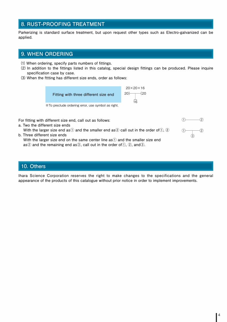
specification�case�by�case.(3)When�the�fttting�has�different�size�ends,�order�as�follows:
Fitting�with�three�different�size�end
※To preclude ordering error, use symbol as right.
For�fitting�with�different�size�end,�call�out�as�follows:a.�Two�the�different�size�endsWith�the�larger�size�end�as①�and�the�smaller�end�as②�call�out�in�the�order�of①,�②
b.�Three�different�size�endsWith�the�larger�size�end�on�the�same�center�line�as①�and�the�smaller�size�endas②�and�the�remaining�end�as③,�call�out�in�the�order�of①,�②,�and③.
10.�OthersIhara� Science� Corporation� reserves� the� right� to� make� changes� to� the� specifications� and� the� general�appearance�of�the�products�of�this�catalogue�without�prior�notice�in�order�to�implement�improvements.
20×20×1620〕 〔20
16〔
① ②
① ②③

5
11.�TIGHTENING�PROCEDUREIt�is�imperative�that�proper�tubes�are�selected�and�the�fittings�are�correctly�tightened�for�the�bite�type�fittings�to� fully� exhibit� itʼs� function.�Bite� type� fittings�can�be�directly� installed�and� tightened�at� the� job� site,�but�by�performing�presetting�as�explained�below�the�piping�operation�can�be�performed�smoothly�and�reliably.It�is�recommended�to�carefully�peruse�the�instruction�manual�before�using.
(1)Presetting1 Cut�the�tube�to�the�required�length�at�a�right�angle.
CAUTION:��Right angle of cut end should be within 90º ±1º.
Remove�all�burrs�from�the�inside�of�cut�end.Exercise� care� not� to� deform� the� tube� or� cause� damages� such� as� deep�scratches�on�the�outside�surface.
CAUTION:��Handle with care to prevent scratches of more than 0.1 mm depth on the tube surface.
2
Firmly� clamp� the� tightening� jig� PJA� in� a� benchvice.� Lubricate� threads� and�tapered�surface�of�the�bore.
WARNING:�The jig must be firmly held in the vice.
3

6
4 Insert�the�nut�first�and�the�sleeve�with�correct�direction�on�to�the�tube
WARNING:�Pay particular attention to the direction of the sleeve.If inserted in the reverse direction, the sleeve can not bite into the tube and result in tube pulling out.
Insert�the�tube�with�the�nut�and�the�sleeve�into�the�tightening�jig.
WARNING:��The tube must be inserted until the tube end firmly bottoms on the fitting body shoulder. If the nut is tightened with the tube end not contacting the shoulder, the sleeve will not adequately bite into the tube and result in pulling out of the tube.
5
Tighten�the�nut�fingertight.6
Determine�the�grip�pointWhile�turning�the�tube�lightly�with�the�fingers,�tightened�the�nut�until�the�point�is�reached�where�the�tube�can�no�longer�be�turned.�This�point�is�referred�to�as�the� grip� point.� It� is� at� this� point� that� the� sleeve� starts� to� bite� into� the� tube.�Draw� identification�matching�mark� so� that� the� amoimt� of� tightening� can� be�determined.
7

7
Tighten�the�nut�1-1/4�turns�with�a�spanner�from�the�grip�point.�However�for�the�types�of�KRE,�KHA,�KHB,�KHC,�KHO,�KAP�which�are�fittings�with�tube�end�configuration�with�grooves,�the�tightening�from�the�finger�tightened�position�(photo�6)�should�be�1-3/4�turn.With�the�above�procedure�the�sleeve�has�been�firmly�seated�into�the�tube.
WARNING:�Provide adequate work space and assure safety when tightening the nut. The wrench must it properly fitted to the nut when tightening.
CAUTION:�If tightening is insufficient, leakage may occur and the tube may pull out. Excessively tightening the nut can damage the fitting and impair its function.
8
Loosen�the�nut,�and�check�the�sleeve.a)�The�edge�of�the�sleeve�must�be�a�few�millimeters�from�the�pipe�edge.b)� The� sleeve� should� not� move� to� axial� direction� though� movement� to�circumferential�direction�is�no�problem.
Note: When tightening a number of tube of the same size, it is recommended that the presetting device PSD is used to ensure proper, correct and effective tightening. Refer to page 9~14 for how to use PSD.
9
(3)DisassemblyThe�bite� type� fitting�assembly�can�be�disassembled�simply�by� loosening� the�nut.�When� remaking� is�done� in�accordance�with� above�mentioned� resetting� procedure� (2),� disassembly� and� remaking� can� be� satisfactorily�repeated�more�than�8�times.
WARNING:�Installing and disassembling under pressure is extremely dangerous and must be prohibited.
When�assembling�a�tube�that�has�been�presetted�to�a�fitting�body,�the�nut�when�being�tightened�with�a�spanner�will�reach�a�point�where�the�torque�will�suddenly�increase.� This� point� is� referred� to� as� the� sharp� torque� rising� point.� The� nut� is�further�tightened�1/4�turn�from�the�sharp�torque�rising�point.�However,�for�the�tube�ends�of�KRE,�KHA,�KHB,�KHC,�KHO�and�KAP,�tighten�by�turning�the�nut�1/6�turn�from� the� sharp� torque� rising� point.�With� the� above� procedures� piping�work� is�completed.
WARNING:��Provide adequate work space and ascertain safety when tightening the nut. The wrench must it properly fitted to the nut when tightening.
CAUTION:��If tightening is insufficent, Ieakage can occur and tube may slip. Excessively tightening the nut can damage the fitting and impair its function.
CAUTION:��After presetting, blow compressed air on the sleeve and the taper bore surface on the fitting body to remove all foreign materials before assembling. If a foreign material becomes caught, the sealing function can be impaired.
Note: Correct the centering of the tube and fitting so the nut can be smoothly tightened to the fitting body.
(2)Resetting

8
12.�Tightening�torque�of�NE�type�bite�type�fittings�for�steel�tube�(reference�values)�The�optimum�method�of�tightening�NE�type�bite�type�fittings�for�steel�tube�is�by�the�number�of�turns�of�the�nut,�but�when�tightening�is�to�be�controlled�by�the�tightening�torque,�the�approximate�tightening�torque�values�are�as�shown� in� the�graph�below.�This�graph�shows� the� relation�between� the�nominal� tube�size�and� the�proper�tightening�torque�(resetting�torque)�of�the�fitting�nut.After�preliminary� tightening�with�PSD-S�or�PSD-B� (preliminary� tightening�device�S� type�and�B� type),� further�tighten�the�nut�l/4�turn�from�the�sharp�torque�rise�point�as�a�guideline.�The�tightening�torque�will�differ�with�the�wall� thickness� of� the� tube,� tube� hardness,� off-centering� during� piping� operation,� fittings� cleaned�with� acid,�alkali,�washing�fluid,�etc.,�and�when�reusing�of�fittings�(reduction�of�lubrication�film�effect).�The�graph�has�been�prepared�for�tubes�shown�in�the�table�and�the�fittings�are�standard�specification�fittings.�When�remaking,�the�torque�to�be�applied�should�be�slightly�higher�than�the�previous�tightening�torque.
Tightening torque values for bite type fittings of steel tubes (reference values)
1000900800700600
500
400
300
200
100
80
60
40
20
6 8 10 15 20 30 40 50
Nominal size
Tightening torque N.m
mm
Tube (OST 2)
OD×Wall thicknessmm
6×1.0
8×1.0
10×1.5
12×1.5
16×2.0
20×2.0
22×2.5
25×2.5
28×3.0
30×3.5
35×4.0
38×4.5
42×5.0
50×6.0

9
13.�PRE-SETTlNG�DEVICE�MODEL�:�PSD-S(1)��Structure�and�Function�of�Pre-Setting�Device�PSD-S
This� device� performs� pre-setting� by� cam�mechanism� as� illustrated� in� the� figure� below� for� bite� type� fittings�within�the�tube�range�of�4�to�20�mm�outside�diameter�or�1/8B�to�3/8B.By�pressing�the�lever�down,�the�clamping�jig�attached�to�the�push�rod�slides�toward�the�clamping�plate�by�cam�action�and�force�the�sleeve�to�bite�into�the�tube.
(2)��STANDARD�COMPONENTS
For� pre-setting�with� this� device� (PSD-S)� it�will� be� necessary� to�select� clamping� jig� and� sleeve� holder� applicable� to� the� outside�diameter�of�the�tube�to�be�used.The�clamping� jigs� and� sleeve�holders� are� not� included�with� the�pre-setting�device�and�must�be�separately�ordered.
(3)��CAUTION
l�)��Cut�the�tube�at�a�right�angle�and�remove�all�burrs�from�the�outside�and�inside�of�the�cut�tube�end. CAUTION:��Cut the tube aiming at an angle of 90º ±1º outer surface of the tube must be free from the scratched
damage of more deeper than 0.1mm.2)��In�case�of�bent�tube,�the�straight�portion�of�the�tube�must�be�longer�than�80mm�from�both�tube�ends.3)�Lubricate�the�moving�parts�of�the�device�with�oil�timely.
CAUTION:��Do not modify the device and jigs. The device may not function properly when modification has been performed.
Figure 1. Pre-setting device mechanism Weight : 17kgs. Figure 2. Detailed drawing of pre-setting components
Tube OD Clamping jig Sleeve holder
4 PJS04−000N(PSD−SJ−4)
PJU04−00SN(PSD−SU−4)
6 PJS06−000E(PSD−SJ−6)
PJU06−00SE(PSD−SU−6E)
8 PJS08−000E(PSD−SJ−8)
PJU08−00SE(PSD−SU−8E)
10 PJS10−000E(PSD−SJ−10)
PJU10−00SE(PSD−SU−10E)
12 PJS12−000E(PSD−SJ−12)
PJU12−00SE(PSD−SU−12E)
15 PJS15−000E(PSD−SJ−15)
PJU15−00SE(PSD−SU−15E)
16 PJS16−000E(PSD−SJ−16)
PJU16−00SE(PSD−SU−16E)
18 PJS18−000E(PSD−SJ−18)
PJU18−00SE(PSD−SU−18E)
20 PJS20−000E(PSD−SJ−20)
PJU20−00SE(PSD−SU−20E)
1/8B PJSll−000N(PSD−SJ−G1/8)
PJU11−00SN(PSD−SU−G1/8)
1/4B PJS13−000E(PSD−SJ−G1/4)
PJU13−00SN(PSD−SU−G1/4)
3/8B PJS17−000N(PSD−SJ−G3/8)
PJU17−00SN(PSD−SU−G1/8)

10
(4)��OPERATION�PROCEDURE�OF�PRE-SETTING�DEVICE�PSD-S
①�Raise�the�lever�and�open�space�between�the�push�rod�and�the�clamping�plate.
②Attach�a�clamping�jig�of�the�same�size�as�the�tube.
③�Insert�the�nut�and�the�sleeve�into�the�tube�with�correct�order�and�direction,�and�set�the�sleeve�holder�between�the�nut�and�the�sleeve.
WARNING:��Make sure the correct direction of sleeve. If the sleeve is facing the incorrect direction, the sleeve will not bite into the tube and tube slippage failure will result.
④Mount�the�tube�with�the�nut�and�the�sleeve�on�the�pre-setting�device.
⑤�The� tube� end�must� be� contacting� and� seated� firmly� against� the� shoulder� of� the�clamping�jig.
WARNING:��When clamping is performed with the tube end not contacting the shoulder of the pre-setting device, biting into the tube will not be satisfactory and cause the tube to slip.
⑥Push�down�on�the�lever.
⑦Clamp�down�on�the�lever�until�it�can�no�longer�be�pressed.
CAUTION:��Press down on the lever until firmly contacting.
⑧�Lift�up�the�lever�to�loose�the�clamp�and�remove�the�tube�with�the�two-piece�sleeve�holder. The�presetting�operation�completed.

11
(5)��FlNAL�TIGHTENlNG
The�tube�that�have�been�pre-set�is�now�ready�to�be�installed�to�the�fitting�body�at�the�piping�site.In�the�installing�operation,�the�tightening�torque�while�tightening�the�nut�with�a�spanner�will�suddenly�increase�upon�reaching�a�certain�point�called�(sharp�torque�rise�point),�then�from�this�point�turn�additionally�l/4�turn�to�complete�the�installation.
WARNING:��Perform tightening of the nut on firm footing, and ascertain the safety of the surrounding. CAUTION:��Insufficient tightening can result in leakage and tube slippage. CAUTION:��Clean the sleeve after pre-setting and the taper bore of the fitting body with cloth and blow clean with
compressed air before assembling. When foreign material becomes caught, sealing function can be impaired.
14.�PRE-SETTING�DEVICE�Model�:�PSD-B(1)��Structure�and�Function�of�Pre-Setting�Device�PSD-B
This�device�performs�pre-setting�of�bite�type�fittings�within�the�tube�range�of�22�to�50mm�outside�diameter�or�1/2B�to�1-1/2B�by�toggle�mechanism�application�as�illustrated�in�the�figure�below.�Upon�reguest,�the�device�for�6mm�to�20mm�diameter�will�be�available.By�turning�the�handle�in�the�right�direction,�the�clamping�jig�attached�to�the�moving�flange�slides�toward�the�fixed�flange�A�by�the�toggle�mechanism�and�forces�the�sleeve�to�bite�into�the�tube.
Figure 1. Diagram of pre-setting device. Weight :33kgs. Figure 2. Details of clamping mechanism

12
(2)��Standard�Components�(sold�separately)
For�pre-setting�with�this�device(PSD-B),�it�will�be�necessary�to�select�clamping�jig�and�sleeve�holder�that�are�applicable�to�the�outside�diameter�of�the�tube�to�be�used�from�the�Table�below.The�clamping�jig�and�nut�holder�are�not�included�in�the�pre-setting�device�and�must�be�separately�purchased.
Outside of Tube Clamping Jig Sleeve Holder Outside of Tube Clamping Jig Sleeve Holder
22 PJB22−000E(PSD−BJ−22E)
PJU22−00BE(PSD−BU−22E) 42 PJB42−000N
(PSD−BJ−42N)PJU42−00BN
(PSD−BU−42)
25 PJB25−000E(PSD−BJ−25E)
PJU25−00BE(PSD−BU−25E) 50 PJB50−000N
(PSD−BJ−50N) Useless
28 PJB28−000E(PSD−BJ−28E)
PJU28−00BE(PSD−BU−28E) 1/2B PJB22−000E
(PSD−BJ−21N)PJU22−00BE
(PSD−BU−22)
30 PJB30−000E(PSD−BJ−30E)
PJU30−00BE(PSD−BU−30E) 3/4B PJB27−000N
(PSD−BJ−27N)PJU28−00BE
(PSD−BU−28)
35 PJB35−000E(PSD−BJ−35E)
PJU35−00BE(PSD−BU−35E) 1B PJB34−000N
(PSD−BJ−34N)PJU35−00BE
(PSD−BU−35)
38 PJB38−000N(PSD−BJ−38N)
PJU38−00BE(PSD−BU−38) 11/4B PJB43−000N
(PSD−BJ−43N)PJU42−00BN
(PSD−BU−42)
40 PJB40−000N(PSD−BJ−40N)
PJU40−00BN(PSD−BU−40) 11/2 PJB48−000N
(PSD−BJ−48N) Useless
(3)��CAUTION
l�)��Cut�the�tube�at�a�right�angle�to�the�center�line,�and�remove�all�burrs�from�the�outside�and�inside�of�the�cut�tube�end. CAUTION:��Aim at obtaining 90º ±1º at the cutting angle of the tube end. Handle with care to prevent scratching deeper
than 0.1 mm on the tube surface.2)�In�case�of�bent�tube,�the�straight�portion�of�the�tube�must�be�longer�than�80mm�from�the�tube�end.3)�Lubricate�the�moving�parts�of�the�device�with�oil.
CAUTION:��Do not perform modification on the device and jig. The device may not function properly when modified.

13
(4)��OPERATION�PROCEDURE�OF�PRE-SETTlNG�DEVICE�PSD-S
l�)��Turn� the�handle� to� the� left(counter�clockwise)�and�open�space�between�the�moving� flange�and�stationary�flange�A.�Attach�a�nut�holder�which�is�corresponding�to�the�tube�diameter�to�the�stationary�flange�A�and�a�clamping�jig�to�the�moving�flange.
WARNING:��Place the device on a stable work bench and firmly fix the device to the work bench so that the device will not turn over or fall during use.
CAUTION:��Firmly fix the nut holder and clamping jig with securing bolts.
Photo 1
2)��Insert� the� nut� and� the� sleeve� into� the� tube,�with�correct�sequence�and�direction�and�set�between�the�nut�holder�and� the�clamping� jig�as�shown� in�Photo�1.Lubricate� the� tapered� part� of� the� jig� and� the�sleeve�with�lubricant.
WARNING:��If the nut or the sleeve is inserted into the tube facing the wrong direction, it may cause the damage of fitting and slipping-off the tube.
Photo 2
3)��Insert�the�tube�into�the�pre-setting�device�so�that�the� tube� end� contacts� the� shoulder� of� the� pre-setting� device.� Clamp� with� the� handle� while�slightly�moving�the�tube�circumferentially�(turning�to�the�right).When�the�tube�no�longer�moves,�temporarily�stop�clamping�with� the�handle�and�set� the�pointer�on�the�indicator�to�“0�(Zero)”��scale.Fix�the�adjustment�screw.
WARNING:��When clamping is performed with the tube end not contacting the shoulder in the pre-setting device, biting effect into the tube will be insufficient and cause the tube to slip.
Photo 3
4)��After�adjusting�the�indicator,�clamp�by�turning�the�handle� until� the� pointer� points� to� the� required�point� on� the� scale.� (In� photo� 3,� the� pointer� is�pointing�to�the�center�on�the�scale.)
WARNING:��Inadequate clamping can result in leakage and tube slippage. However, excessive clamping can cause damage of fitting.
Photo 4
5)��Loosen� by� turning� the� handle� (to� the� left)� and�remove�the�tube.This�completes�the�pre-setting�procedure.
Note:��An�operation�procedure�plate�is�attached�on�the�top�cover�of�the�device�and�can�be�used�as�reference.

14
(5)��本締付け/FlNAL�TIGHTENlNG
The�tube�that�have�been�pre-set�is�now�ready�to�be�installed�to�the�fitting�body�at�the�piping�site.In�the�installing�operation,�the�tightening�torque�while�tightening�the�nut�with�a�spanner�will�suddenly�increase�upon�reaching�a�certain�point(sharp�torque�rise�point),�and�from�this�point�an�additional�l/4�turn�will�complete�the�final�tightening.
WARNING:��Perform tightening of the nut on firm footing, and ascertain the safety of the surrounding. CAUTION:��Insufficient tightening can result in leakage and tube slippage. CAUTION:��Clean the sleeve after pre-setting and the taper bore of the fitting body with cloth and blow clean with
compressed air before assembling. When foreign matter becomes caught, sealing function can be impaired.
15.�Hydraulic�Pre-Setting�Device�MODEL�:�PSD-HTThe�hydraulic�pre-setting�device�enables�pre-setting�for�all�sizes�of�steel�tube�bite�type�fittings,�and�long�tube�with�three�dimensional�bending�which�required�support�with�manual�type�pre-setting�device�can�be�performed�by�one�operator�with�the�foot�switch.
Operation�procedure1.�Turn�on�the�power�and�start�the�hydraulic�pump.2.�By�turning�the�relief�valve�adjustment�handle.�Set�the�pre-set�pressure�as�specified�per�the�outer�diameter�and�wall�thickness�of�the�tube�operating�the�foot�switch.�
3.�Install�the�nut�and�sleeve�into�the�tube�and�insert�the�clamping�jig�to�the�front�of�the�cylinder.4.�Turn�on�the�foot�switch.�The�cylinder�will�advance�and�perform�pre-setting.5.�When�pre-setting�has�been�completed,�the�cylinder�will�automatically�return.6.�In�case�of�emergency�during�operation,�push�the�emergency�stop�button.
Details�of�the�clamping�mechanism
WARNING:��Before use, read the operation manual and opertate correctly.

15
NE�BITE�TYPE�TUBE�FITTINGS VISUAL INDEX
Straight Thread Connector: KCO O-ring Seal Straight Thread Connector: KCD Straight Thread Extended Male Connector: KCGExtended Male Connector: KCC
Female Connector: KSA Bulkhead Female Socket: KSS Connector for Pressure Gauge: KGAStraight Thread Connector: KCJ
Weld Male Connector: KCW Union Elbow: KLA Bulkhead Union Elbow: KSLConnector for Pressure Gauge (O-Ring Seal): KGO
Extended Male Elbow: KLL O-Seal Male Elbow: KLO O-Seal Extended Male Elbow: KLGMale Elbow: KLN
Stud Elbow (B type): KMB Stud Elbow (Ctype): KMC Female Elbow: KLFAdjustable Elbow: KLC
Male Run Tee: KTK Male Branch Tee: KTN O-Seal Male Branch Tee: KTOUnion Tee: KTA
Bulkhead Union: KSU Bulkhead Weld Union: KUW Male Connector: KCTUnion: KUA

16
NE�BITE�TYPE�TUBE�FITTINGS VISUAL INDEX
Cap: KCA Plug: KBA Reducer: KREUnion Cross: KXA
Straight Thread Adapter: KHB O-Ring Seal Straight Thread Adapter: KHO Straight ThreadAdapter (For Copper Gasket): KHCAdapter: KHA
Air-Purge Valve: SAP Male Seat Hose Connection Union: KUC Female Seat Hose Connection Union: KUDAir-Purge Valve: KAP
Female Seat Hose Connection Bulkhead Union: KUF Male Seat Hose Connection Union Elbow: KLD Female Seat Hose Connection Union Elbow: KLEMale Seat Hose Connection Bulkhead Union: KUE
Female Seat Hose Connection Bulkhead Elbow: KLS Female Seat Hose Connection Run Tee: KTG Male Seat Hose Connection Run Tee: KTJMale Seat Hose Connection Bulkhead Elbow: KLH
Male Seat Hose Connection Branch Tee: KTD Female Seat Hose Connection Elbow: HLE Male Seat Hose Connection Elbow: HLDFemale Seat Hose Connection Branch Tee: KTE
Female Branch Tee: KTH Adjustable Run Tee: KTC Adjustable Branch Tee: KTBFemale Run Tee: KTF

17
NE�BITE�TYPE�TUBE�FITTINGS VISUAL INDEX
Check Union: KZU Check Elbow: KZL Check Connecter: KZCBonded Seal: KP-C
Orifice Adjustable Fitting: KTP
Sleeve: KKO Hand Presetting Tool: PJA Copper Gasket: KP-ANut: KKN
Directions�meaning�shown�in�this�catalogue WARNING:��Irregular handling with disregard for this direction can induce physical disability and accidental death. CAUTION:��Irregular handling with disregard for this direction can induce fanctional defect of bite tipe fitting.


2014.2K
・Head Office/ �11-3 Takanawa 3-chome Minato-ku, Tokyo 108-0074 Japan TEL: 03-6721-6981 FAX: 03-6721-6991
WARNING If you don’ t select and handle fittings, valves and related accessories in an adequate manner, it may damage human beings and applicable systems.Within the responsibility and authorization of users and piping designers, fittings, valves and related accessories shall be adequately selected, assembled, used and maintained based on the applicable conditions and product conformity to the system to be applied. Please read carefully our operation manual and feel free to contact with Ihara if you have any question or request.
East Japan Sales Office: 11-3 Takanawa 3-chome Minato-ku, Tokyo 108-0074 Japan TEL: 03-6721-6981 FAX: 03-6721-6991Tohoku Sales Office: 5600-3, Higashineko, Oaza, Higashine city, Yamagata prefecture 999-3701 TEL: 0237-43-7802 FAX: 0237-43-7803Chubu Sales Office: Tsukasa Building, 3-14-19, Chiyoda, Naka ward, Nagoya city, Aichi prefecture 460-0012 TEL: 052-323-2627 FAX: 052-323-2630Kansai Sales Office: 7F, GL Osaka Building, 4-1-18, Tenma, Kita ward Osaka city, Osaka prefecture 530-0043 TEL: 06-6358-9255 FAX: 06-6358-9260Kyushu Sales Office: 103, Maison de Sophie, 1-1-8, Onoue, Kumamoto city, Kumamoto prefecture 862-0913 TEL: 096-386-5353 FAX: 096-386-5354
Overseas Sales NetworkTaiwan: TaichungChina: ShanghaiKorea: SeoulThailand: BangkokU. S. A.: Irving, Texas
ISO9001, ISO14001 Certified OfficeCertified office for high-pressure gas facility testing and manufacturing,certified office for N valves and N-II fittingsTÜV Rheinland Japan Ltd. Certified Plant
■ URL:http://www.ihara-sc.co.jp■ The contents of this catalog are subject to change without notice due to improvement of products or other reasons.