igrow 100 series™ - home - link4 greenhouse controls · igrow 100 series™ installation and...
TRANSCRIPT

iGrow 100 Series™
Installation and User’s ManualApril 2012 Edition - Version 5.1

1iGrow Series 100 Manual
ContentsIntroduction...................................................................................................................... 3
CustomerService................................................................................................................ 4
TermsandConditions......................................................................................................... 5
BeforeyouBegin................................................................................................................ 6 TemperatureControl............................................................................................... 6 Deadbands............................................................................................................... 7 Setpoints.................................................................................................................. 7 Ramping................................................................................................................... 7
ControlStrategy.................................................................................................................. 9 SetpointandStagingWorksheets............................................................................ 9
HardwareInstallation....................................................................................................... 10 ContentInspection................................................................................................ 10 RecommendedTools.............................................................................................. 10 MountingtheiGrowSeries100™.......................................................................... 10
iGrowSeries100™Overview............................................................................................ 12 OpeningtheiGrowSeries100™............................................................................ 12 InternalLayout....................................................................................................... 13
WiringtheiGrowSeries100™.......................................................................................... 14 PowerSupplyInstallation...................................................................................... 14 OutputInstallation................................................................................................. 15 ControlRelays&Contactors.................................................................................. 16 IndoorAirTemperatureProbeInstallation............................................................ 17
Programming................................................................................................................... 19 BeforeYouBegin.................................................................................................... 19 iGrowSeries100™MainScreenLayout................................................................. 19 Navigation.............................................................................................................. 20
StatusScreens........................................................................................................ 21 MainStatusScreens.................................................................................... 21 ProgrammingScreens................................................................................. 22
SetpointProgramming..................................................................................................... 23
Reports/Logs................................................................................................................... 28 ReturnonInvestment............................................................................................ 29 Graphing................................................................................................................ 30 EquipmentCosts.................................................................................................... 34 EnergyCosts........................................................................................................... 35 EquipmentUsage................................................................................................... 36 EnergyUsage......................................................................................................... 37 EventLogs.............................................................................................................. 38

iGrow Series 100 Manual2
SystemSetup.................................................................................................................... 40
EquipmentSetup................................................................................................... 41 GeneralType............................................................................................... 44 EnergyType................................................................................................. 50 AssignStages............................................................................................... 55 TemperatureStages..................................................................................... 56 HumidityStages.......................................................................................... 58 ResetRuntime............................................................................................. 60
Save&Restore....................................................................................................... 61 Save&RestoreConfigurations.................................................................... 62 SaveLogFiles.............................................................................................. 64
SensorSetup.......................................................................................................... 66 MapSensors................................................................................................ 67 CalibrateSensors......................................................................................... 68 SelfTestSetUp............................................................................................ 69 AnalogSensorMapping.............................................................................. 70
Time&DateSetup................................................................................................. 71 SetTime...................................................................................................... 72 SetDate....................................................................................................... 73
LocationSetup....................................................................................................... 74
EnergyCost............................................................................................................ 75
CommunicationSetup........................................................................................... 78 WeatherStationSetup................................................................................ 79 IPAddressSetup......................................................................................... 80
MeasurementUnits............................................................................................... 81 Advanced............................................................................................................... 82 HumiditySettings........................................................................................ 83 ROISettings................................................................................................. 84 ClearAllData............................................................................................... 84 UnitInfo...................................................................................................... 84 StageDelay.................................................................................................. 85 BeginBootload............................................................................................ 85 UITest.......................................................................................................... 86 Password.................................................................................................... 86
Stages/Staging.................................................................................................................. 87
CompleteMenuStructureListing..................................................................................... 88
ResettingtheController................................................................................................. 108

3iGrow Series 100 Manual
IntroductionWelcometoiGrowSeries100™,Link4’sIntelligentGreenhouseEnvironmentalController.TheiGrowSeries100™representsthelatestingreenhouseenvironmentalcontrolauto-mation.iGrowSeries100™enablesyoutocontrolandintegrateavarietyofequipmentinyourgreenhouse.Yourheating,cooling,venting,shading,humidity,CO2,andlightingneedsarelinkedtogetherintooneflexible,easy-to-usesystem.
Link4canofferreliableservicebecausewearestaffedbythedesignerandengineersthatdevelopedtheiGrowSeries100™.IndesigningtheiGrowSeries100™itwasourpurposetodesignacontrollerspecificallyforthedemandsandcostconcernsforsmalltomidsizegrowersandnoothercontrollerhasabetterfeaturetopriceratiothaniGrowSeries100™.Yourgreenhousecontrolsystemshouldimprovethequalityandefficiencyofyouropera-tion. iGrowSeries100™offersquick installation,anddynamicprogrammingflexibilityforeasierandmoreaccurategreenhousemanagementgivingyouthefreedomforyoutofocusonplantsandprofits.
ThereasonwhywestandoutfromothersisbecauseofourLink4Promise:Ourpassionistoprovidegrowerswithintelligentcontrolsolutions.Weunderstandcontrollingyourgrowingenvironmentiscriticaltoyoursuccess.Therefore,ourcommitmentistobuildoutstandingcontrollersandtoprovideexcellentsupportsothatyoucanknowwithconfi-dencethattheiGrowSeries100™systemisrightforyou.

iGrow Series 100 Manual4
Customer ServiceLink4hasawell-trainedcustomersupportstaffthatisreadytohelp.Ourcustomerservicecenteriscommittedtoyourgreenhousebusiness24/7throughourwebsiteorservicelineforaccesstosolutionsforyourcontrollerneeds.Beforeyoucontactus,pleasewritedownthemodelnumberandserialnumberlocatedinsidetheiGrowSeries100™enclosuresothatwecanserveyoubetter.
Address:Link4Corporation22725LaPalmaAveYorbaLinda,CA92887
Telephone:SUPPORT866.755.LINK(5465)
Web:www.link4corp.com
E-mail:SALES [email protected] [email protected]
ThereisextensiveonlinesupportforallLink4productsforregisteredusersatwww.link4corp.com.Registrationisprovidedatnocharge.

5iGrow Series 100 Manual
Terms and ConditionsWarranty
Link4warrantsthatthegoodssoldunderthiscontractwillbefreefromdefectsinmaterialandwork-manshipforaperiodof12monthsafterthedateofpurchase.Thiswarrantywillbelimitedtotherepairandreplacementofpartsandthenecessarylaborandservicesrequiredtorepairthegoods.ITISEXPRESSLYAGREEDTHATTHISWARRANTYWILLBEINLIEUOFALLWARRANTIESOFFITNESSANDINLIEUOFTHEWARRANTYOFMERCHANTABILITY.
Moreover,anydescriptionofthegoodscontainedinthiscontractisforthesolepurposeofidentify-ingthem,isnotpartofthebasisofthebargain,anddoesnotconstituteawarrantythatthegoodswillconformtothatdescription.Theuseofanysampleormodelinconnectionwiththiscontractisforillustrativepurposesonly,isnotpartofthebasisofthebargain,andisnottobeconstruedasawarrantythatthegoodswillconformtothesampleormodel.NoaffirmationoffactorpromisemadebyLink4,whetherornotinthiscontract,willconstituteawarrantythatthegoodswillconformtotheaffirmationorpromise.
Link4shallnotberesponsibleforreplacement(s)orrepair(s)whichbecomedefectivefromuserneg-ligence,modification,abuseand/oranytypesof improperusage. Nonconformancetoanyofthespecificationsintheproductmanualwillvoidthewarranty.Furthermore,ourliabilitytothegoodssold,whetheronwarranty,contract,ornegligence,willbereleasedupontheexpirationofthewar-rantyperiodwhenallsuchliabilityshallterminate.
Link4 shallnotbe responsible forany lossor claimsdue toconsequentialdamagesaffordby theBuyer.Link4alsoreservestherighttomakeanynecessarychangestofeaturesandspecificationstoconditionorwarranty.
Returns
MerchandisecannotbereturnedwithoutaReturnMerchandiseAuthorization(RMA)numberfromLink4.Requestsforpermissiontoreturndefectiveitemsmustbemadewithin(14)fourteendaysafterreceiptofshipment.ALink4RMA#forapprovedreturnsmustappearonboththecustomer’sshippingcartonandtherelatedreceiptmemo.Partsunderwarrantywillberepairedatnocharge.Otherreturneditemswillbesubjectedtothefollowingrestockingcharges:20%fornovalueaddeditems,40%forvalueaddeditems,and75%forcustomdesignedorbuilttospecificationitems.
Repair
ArepairordermustalsohaveaLink4ReturnMerchandiseAuthorization(RMA)number.Repairsthatarenotcoveredbythewarrantywillbebilledonamaterialandlaborbasis.ItemsreturnedforrepairmustbesenttoLink4withprepaidreturntransportationLink4willnotberesponsiblefordamage(s)duetoimproperpackagingorshippinganddeliveryofitemsreturnedforrepair.
Additional Costs
ItisexpresslyagreedthatBuyerwillreimburseLink4foranyadditionalcostsattributabletochangesinthespecifications,directions,ordesignoftheitemsfurnishedwhicharerequestedorapprovedbyBuyeratLink4’slistedretailpricesineffectatthetimesuchchangesareordered.
Governing Law
Thevalidityofthiscontractandofanyofitstermsorprovisions,aswellastherightsanddutiesofthepartiesunderthiscontract,shallbeconstruedpursuanttoandinaccordancewiththelawofCalifor-nia.ThepartiesspecificallyagreetosubmittothejurisdictionofthecourtsofCalifornia.

iGrow Series 100 Manual6
Before you BeginTemperature Control WiththeiGrowSeries100™youcanprogramacoolingtemperaturetargetcalleda“CoolSetpoint”andaheatingtemperaturetargetcalleda“HeatSetpoint”. Thetemperaturerangebetweenthesetwotargetsiscalledthe“Normal”temperaturerangeorstage.IfthegreenhousetemperatureiswithintheNormaltemperaturebandusuallynoneofthecoolingorheatingequipmentison.However,somecirculationfans(oftencalledhorizon-talairflow(HAF)fans)maybeactivetomaintainairmovementwithinthegreenhouseenvironment.
Whenever the temperaturewithin the greenhousemoves above the cool setpoint, orbelowtheheatsetpoint(fallsoutsidetheNormaltemperaturerange)theiGrowSeries100™willentercoolingorheatingstagestobringitbackinline.WiththeiGrowSeries100™youcanprogramuptosixcoolingandtwoheatingstages.ThesestagesgofromCool1toCool6andHeat1toHeat2.Cool1andHeat1aretheleastaggressivewithCool6andHeat2themostaggressive.Inyourprogramyouwilldeterminewhatequipmentyouwanttobeactiveineachofthestages.
WhentheairtemperatureinthegreenhouserisesabovetheCoolSetpoint,thesystementersthefirststageofcooling,referredtoasCool1.Ifthetemperaturecontinuestorise,thesystemwillenterthesecondstage,Cool2,thenthethirdstage,Cool3andsoforth.Ateachincreasingcoolingstage,morecoolingwillbebroughttoattempttobringtheairtemperaturebelowthecoolsetpointandwithinthetarget“Normal”temperaturerange.Heatingworksthesameway.
Inconsideringthedifferencebetweeneachheatingandcoolingstagethereisavariableintheprogramwhichisthenumberofdegreesbetweeneachheatingandcoolingstagecalledthe“StageSeparation”or‘StageWidth”.Wheneverthetemperaturerisesabovethecoolsetpoint,theiGrowSeries100™willactivatetheappropriateequipmenttobringthegreenhousetothenormaltemperaturerange.Ifthestagewidthis1degreeandthetemperaturerises1.1degreesabovethecoolsetpoint,thenthecontrollerwillbeactiveinC2coolingstage.Thesamegoesfortheheatingstagewhenthetemperaturedropsbelowtheheatingsetpoints.InFigure1.1,thereisanexamplewithfourcoolingstagesandtwoheatingstages.

7iGrow Series 100 Manual
DeadbandsIfthetemperatureisbelowthecoolsetpointandrisesintothefirststageofcooling,somecoolingequipmentwillbeturnedon.Thismaythenlowerthetemperatureandbringitintothenormalrange.Inordertokeeptheequipmentfromoscillating,a“Deadband”isemployedwhenthetemperatureisbetweenstages.InFigure1.1thedeadbandissetat1degreesothatwhenthegreenhouseisattemptingtoreturntoNormaltemperaturefromC4toC3thecontrollerwilluseadeadbandof1degreetokeeptheequipmentfromoscillatingoffandon.Now,when the temperaturedropsbelow thecool setpoint, thesystemremainsintheCool1stageuntilthetemperaturedropsbelowtheCoolDeadband.Theconceptsthatwedescribedforcoolingoperateinthesamemannerforheating.
SetpointsYouwillbeabletouseupto3setpointsina24hourtimeperiod.Withineachtwenty-fourhourperiodSetpointsarebasedontimeandtemperaturetoproducethedeisredenvironment.Byplacingsetpointsduringdifferenttimesofthedayyoucanregulatethetemperaturewithinarangefortargettemperaturesandhumidity(humiditysensorsoldseperately).Whenasetpointisineffectatacertaintimelengththecontrollerwillacti-vatethenecessaryequipmentinheatingandcoolstagestobringtheenvironmentbacktoNorm.Thesameapplieswhenthehumidityrisesorfallsbeyondthetargetlow/highsetpoint.Whenoneormoresetpointsareusedthesecondorsubsequentsetpointswillbecometheactivesetpointatthestarttimeandtheprevioussetpointwillend.
RampingInaddition,youhavetheoptionofatemperaturerampbetweenthesetpoints.Eachset-pointtimeperiodbeginswithaRamptime.Thebenefitoframpingallowsyoutomakesmoothtransitionswithinthegreenhousesothattheplantsdon’texperiencetempera-tureshock. Rampingalsosavesenergy,whichtranslatesdirectly into loweroperatingcosts.
Intheexampleonthefollowingpage(Figure1.1),thestarttimeis8:00amwitha60min-uteramptime.Theramptimeenablesasmoothtransitionofthetargettemperaturesbetweenthesetpointtimeperiods.Ofcourse,theramptimescanbesetto0andinthiscasetherewillbeanimmediatesteptransitioninthesetpoints.Figure1.1alsoshowsatypicalexampleofastagingworksheet.

iGrow Series 100 Manual8
Setpoint 1issetto8:00amwitha60minuteRamp,Tempissetas68to72.0°FSetpoint 2issetto6:00pmwitha30minuteRamp,Tempissetas67to70.5°F
Figure 1.1 Example of Setpoints, Staging, & Deadbands
SET POINTS START TIME
DAY 6:00 AM
NIGHT 7:00 PMDIF NOT USED
EQUIPMENT NAME
H2 H1 N C1 C2 C3 C4 C5 C6 De-H Hum
1 RVM-1 ROOF VENT OPEN 20% 40% 60% 80% 99% 99% 15%
2 RVM-1 ROOF VENT CLOSE
3 SWM-1 SIDEWALL OPEN 0% 10% 80% 99% 99% 99% 0%
4 SWM-1 SIDEWALL CLOSE
5 EX-1 EXHAUST FANS ON ON ON ON
6 HAF-1 HAF FANS ON ON ON ON ON ON ON ON ON ON
7 HT-1 HEAT NORTH ON OFF
8 HT-2 HEAT SOUTH ON ON
60
OUTPUTS
FOR ON/OFF & VENT ONLY
HEAT STAGES COOLING STAGES H
UM
IDIF
ICA
TIO
N
STAG
ES
68
55
72
65
30 55 80
55 80
TEMPERATURERAMPTIME HUMIDITY
Low Set Pt.(°F/°C)
High Set Pt.(°F/°C) (min)
Low Set Pt.(%)
High Set Pt.(%)
12am 1 2 3 4 5 6 7 8 9 10 11 12pm 1 2 3 4 5 86 7 9 10 11
65° F
70° F
75° F
Setpoint 1Day Cool72.0° F
Setpoint 1Day Heat68.0° F
Setpoint 2Night Cool70.5° F
Beginningof
Ram
ptime
8:00am
Endof
Ram
ptime
9:00am
Cool Stage 1
Cool Stage 2
Cool Stage 3
Cool Stage 4
Heat Stage 1
Heat Stage 2
Setpoint 2Night Heat67.0° F
Endof
Ram
ptime
6:30pm
Beginningof
Ram
ptime
6:00pm
1° F Deadbands
SAMPLE WORKSHEET

9iGrow Series 100 Manual
Control StrategyPriortoinstallingandprogrammingtheiGrowSeries100™itisimportanttodetermineanoverallstrategytocontroltheenvironmentinthegreenhouse.TheiGrowSeries100™isanextremelyflexibleandpowerfuldevice,thusadditionalcareandplanningarerequired.
Inordertoaidyouwiththeprocess,Link4hasprovidedseveralworksheetsinthefollow-ingpages.Itisassumedthatyoualreadypossessageneralunderstandingofgreenhousecontrols.Ifnot,pleasereviewthissectioncarefully.
Itisrecommendedthatyoumakecopiesofthesesheetsbeforeusingthem.Theywillbeusefulinthefutureshouldyourcontrolneedschange.
Setpoint and Staging Worksheets
Figure 1.2 Setpoint & Staging Worksheets
SET POINTS START TIME
DAYNIGHT
DIF
EQUIPMENT NAME
H2 H1 N C1 C2 C3 C4 C5 C6 De-H Hum
12345678
OUTPUTS COOLING STAGES
Low Set Pt.(%)
High Set Pt.(%)(min)
TEMPERATURELow Set Pt.
(°F/°C)High Set Pt.
(°F/°C)
HEAT STAGES H
UM
IDIF
ICA
TIO
N
STAG
ES
FOR ON/OFF & VENT ONLY
RAMPTIME HUMIDITY

iGrow Series 100 Manual10
Hardware InstallationContent InspectionThepackageshouldcomecompletewithaniGrowSeries100™unit,a12VDCpowersup-ply,atemperaturesensorprobewith50’ofcableattached,and4–SelfDrillingScrews.Uponarrival,checkthecontentswiththepackinglistfordamagedormissingcomponents(Ifyouhavethe Integrated iGrow100SeriesModel,simplymountthepanelusingthemountingfeetprovided).
Additionalaccessoriessuchasdigitaltemperature/humiditysensor,outsidetemperaturesensor,lightsensor,windandrainsensorscanbepurchasedandaddedatanytime.
Makesureyouhaveall items,allassociatedhardware,andnecessarytoolsbeforeyoubegininstallation.Ifthereisanyvisibledamageormissingparts,pleasecontactourcus-tomerserviceatsupport@link4corp.comor1-866-755-LINKorfaxusat714.558.9782.
1. iGrowSeries100™unit2. 12VDCexternalPowerSupply3. Temperatureprobewith50ft.cable4. 4pcs–PhilipsHeadSelfDrillingScrews5. 4pcs–3/8”Drive,HexHeadSelfDrillingScrews(integratedoptiononly)
Recommended Tools1. Drill2. 1/8”highspeedsteeldrillbit3. Phillipsheadscrewdriver4. Level(optional)5. Pencil
Mounting the iGrow Series 100™1. First,findasecure locationtomount the iGrowSeries100™controller. Thearea
shouldbeawayfromdirectsunlight,condensinghumidity,water,rain,orextremetemperatures. It shouldbemounted inaneasilyaccessible locationat theuser’seyelevel.
2. Since the iGrowSeries100™ isequippedwithahingeddoorandahingedaccesspanelforeasyserviceandinstallation,makesurethereisadequateworkspace.Therecommendedclearanceis8”fromeachsideofthecontrolunit.

11iGrow Series 100 Manual
3. TheiGrowSeries100™comeswitha12VDCwallmountpowersupply.Makesurethere is apoweroutletwithinapproximately6 feet. It is recommended that theoutletisnotswitchedandisonacircuitthatisindependentofanynoisy,highpowerequipment.Theuseofasealedoutletisrecommendedifthepoweroutputisex-posedtomoisture.
4. Identifywhat typeof surfaceyouwill bemounting the iGrowSeries100™ to. In-cludedare4self-drillingscrewsformountingtobeamorwoodpanel.
5. Thereare4mountingpointsontheinsideoftheiGrowSeries100.Usingtheappro-priatetoolsdependingonyoursurface,mounttheiGrowSeries100™.Refertothefigurebelow(2.1)foravisualpicture.
Figure 2.1 iGrow Series 100™ Installation Instructions

iGrow Series 100 Manual12
iGrow Series 100™ OverviewNowthattheiGrowSeries100™hasbeenmounted,takesometimetolookoverthefrontpanel.TheiGrowSeries100™hasmanyfeaturestohelpgiveyouthegrowingadvantage.Figure2.2belowgivesanoverviewofthemaincomponentsthattheiGrowSeries100™hastooffer.
Figure 2.2 Front View of iGrow Series 100™
Opening the iGrow Series 100™Openthehingeddoorbysimultaneouslydepressingonthetwosideejectorbuttonswithyourthumbs,whileusingyourmiddleandindexfingersforsupport.
Figure 2.3 Proper finger positions for door opening

13iGrow Series 100 Manual
Internal LayoutFigure2.4showshowtheiGrowSeries100™looksontheinside.Takenoticeoftheboardandfamiliarizeyourselfwiththeinternallayoutbeforebeginningthewiringprocess.
Figure 2.4 Internal Layout of the iGrow Series 100™ PCB
8 Re
lay
Out
put
Term
inal
Pai
rs
Opt
iona
lCo
mm
unic
atio
nsM
odul
e
DC
Inpu
tPo
wer
Insi
de T
empe
ratu
re S
enso
rfo
r use
with
pro
vide
d Te
mpe
ratu
re P
robe
Tem
pera
ture
/ H
umid
ity
Sens
orfo
r use
with
opt
iona
l Tem
p/H
umid
ity S
enso
r
Wea
ther
Sta
tion
Inpu
ts
Back
up B
atte
ry
Mas
ter R
eset
Butt
on
Man
ual O
verr
ide
Swit
ches
Ana
log
Inpu
tsU
SB S
tora
geIn
put
Cont
rast
Adj
ustm
ent
for F
ront
Pan
el D
ispl
ayRJ
45 C
onne
ctor
for P
C Co
nnec
tivity

iGrow Series 100 Manual14
Wiring the iGrow Series 100™Warning: Do Not Plug-in the Power while wiring the iGrow Series 100™ and keep the manual override switches in the OFF position.
It isrecommendedthatallconnectionsbemadethroughliquidtightconnectorsatthebottomofthe iGrowSeries100™.Theseglandscompressaroundthecablestoformawatertightseal.Makinganyadditionalholesinthetop,sides,orbackoftheenclosurecanresultinwatercondensationinsidetheunit,causingdamagetothecontroller.FailuretoinstalltoLink4’sspecificationwillvoidthewarranty.
InpreparationforthecontrolwiringyoushoulddecidetheiGrowSeries100™outputas-signmentsandcontrolstrategy.Formoreinformationonoutputassignmentandcontrolstrategies,pleaserefertotheControlStrategysectionandtheappropriateworksheetsforthismanual.
Power Supply Installation1. IfyouwanttonavigatethroughtheiGrowSeries100™toseesomeofthefeatures
andtofamiliarizeyourselfwithhowitworks,beginbyinstallingthepowersupply.MakesurethepowersupplyisNOTpluggedinwhileinstallinganyotheroutputsorinputs.
2. BeginthepowerinstallationbymeasuringthedistancebetweenwheretheiGrowSeries100™ismountedandthepowersocket.Thereneedstobeabout6feetbe-tweenthetwo.Ifthepowersupplyistooshort,thenuseapowerextensioncord.Note:extensioncordisrecommendedfortemporaryusageonly.
3. Makesureall8manualtoggleswitchesareintheOFFposition.
4. Taketheopenend(thetwostrippedandtinnedleads)ofthepowersupply.TheREDleadisthe12VDCpowerandtheBLACKleadistheGND(ground).Routethepowerleadthroughtheleftmostliquidtightconnector.Remembernottopluginthepowersupplyatthistime
5. LocatetheDCInputPowerterminalonthePCB.SeeFigure2.4andFigure3.1.
6. ConnecttheGroundlead(BLACK)totheGNDterminalusinga#0screwdriver.Makesuretomakeitasnugfit.Alsotakecarenottoover-tightentheconnection.
7. Thesameprocessisusedtoconnectthe12Vpowerlead(RED)tothe12Vterminalusinga#0flatdrivescrewdriver.

15iGrow Series 100 Manual
8. Now, if needed, you can plug in the power to navigate through the iGrow Series100™. Ifyoucontinueto installdifferentoutputsor inputsremembertokeepthepowersupplyunplugged.
Figure 3.1 Wiring the Power Supply
Output InstallationThegeneralinstallationstrategyforthissectionistoinstalltheoutputequipmentinthegreenhousefirstand then the inputs tokeep thecablesorganized in the iGrowSeries100™.Itisassumedthatatthispointyouhavealreadyplannedthechannelassignment.Ifyouhavenot,pleasereferbacktoControlStrategy(page9).
AllcablescomingintoandoutoftheiGrowSeries100™shouldgothroughtheliquidtightconnectorsatthebottomoftheenclosure.Inordertominimizeinterference,itisrecom-mendedthatthesensor inputwiresnotberoutedthroughthesameconnectorasthecontrolpower.Forbestresults,routeallsensorwiresthroughtheleftmostliquidtightconnectorandthenmovetowardtheright.Thepowerwiresandnon-sensorwiresareroutedthroughtherightmostconnector,andifneeded,thenextconnectorover.

iGrow Series 100 Manual16
Control Relays & ContactorsYour iGrowSeries100™has4or8outputrelaysthatareprovidedasdrycontacts, i.e.switchclosures.IfanoutputisactivatedtoON,theswitchis“closed”(shorted);andifitisactivatedtoOFF,theswitchis“open”(nocontinuitybetweenthepositiveandnegativeterminals).
Theboardmountedrelaysareintendedas“pilot”relays.FormostloadsyouwillwanttheiGrowSeries100™outputstocontrolaloadrelayorcontactorthatisconnectedtothemotor.However,insomecasessuchasirrigationvalvesthatare24VAC,youcandrivethemdirectlyassumingthatyouarewiringonlyoneortwovalvesperrelay.Themaxi-mumruncurrentrecommendedforeachoftheiGrowSeries100relaysis1amp.
“Dry” Contact Design “Dry”contactinstallationdesignisusedwhenauserwantstoisolateequipmentandusetransformersforeverypieceofequipment.
Figure 3.2 Output Wiring Example

17iGrow Series 100 Manual
Indoor Air Temperature Probe InstallationThe iGrowSeries100™ isshippedwithastandardtemperatureprobe. Thissensor in-cludes50-feetofsensorcable.Normallyyouwillwanttohangthesensornearthecroplevelclosetothecenterofthecontrolledenvironment.Itisimportanttokeepthesensorawayfromirrigationemitters,unitheaters,etc.thatwilleffecttheaccuracyofthesensor.
1. First,openupthefrontdoor,asshowninFigure2.3.
2. Findacentrallocationinthegreenhouseandletithangrelativelyclosetotheheightofwheretheplantswillbe.
3. Runthefreeendofthesensorcabletothecontrollerunit.
4. Youmayextendthesensorcableasneeded,butmakesuretouseanadapterandwireapprovedbyLink4tomakeanyextensions(thewireandadaptercanbepur-chasedfromLink4). Itshouldbenotedthatthecontroller iscalibratedfora50ft.temperatureprobe.Ifadditionalwiresareaddedorremoved,softwarecalibrationwillbenecessarytoensurepropertemperaturemeasurementaccuracy.
5. Carefullyinsertthecablethroughtherightmostwatertightfittingatthebottomoftheenclosure.Itiseasytostripinsulationand/orbreakwireswhenpullingcable.Ifyouwanttobundlewirestighter,useUVprotected“tiewraps”(typicallyblueorblack),anddonotover-tighten.
Note: If any splices are needed to extend cable length, make certain they are WATERTIGHT. Water or fertilizer infiltration WILL cause unstable sensor readings.
6. ConnectthewiresasshowninFigure3.3.
7. Keep sensor cablesaway from interference sources, includinghighvoltagepowerwiring, inverters,motorcontrollers,mercuryarc,orsodiumlampcircuits. Placingsensorcablenearsuchwiringmaycauseerraticsensorreadings.
8. Afterinstallingthesensor,itisrecommendedthatsensorsbecheckedbyplugginginthepowersupplyandtestingundervariousconditionsbeforemovingoninordertomakesurethesensorworksproperlyandaccurately.Testthetemperaturebychang-ingtheindoortemperaturetoseeifitisreadingproperly.Aftertestingremembertounplugtheunittocontinueinstallingothersensors.
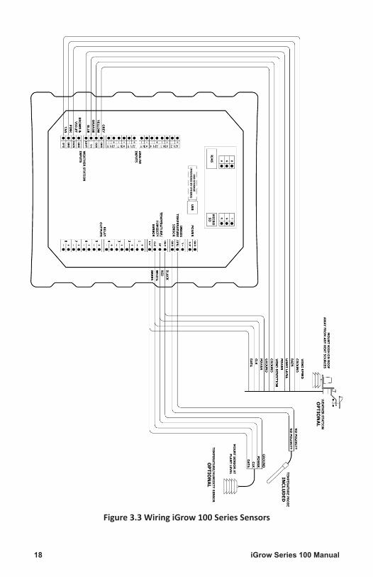
iGrow Series 100 Manual18
Figure 3.3 Wiring iGrow 100 Series Sensors
19iGrow Series 100 Manual
Programming
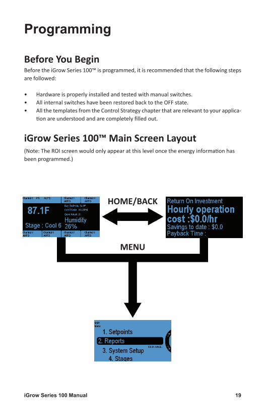
Before You BeginBeforetheiGrowSeries100™isprogrammed,itisrecommendedthatthefollowingstepsarefollowed:
• Hardwareisproperlyinstalledandtestedwithmanualswitches.• AllinternalswitcheshavebeenrestoredbacktotheOFFstate.• AllthetemplatesfromtheControlStrategychapterthatarerelevanttoyourapplica-
tionareunderstoodandarecompletelyfilledout.
iGrow Series 100™ Main Screen Layout(Note:TheROIscreenwouldonlyappearatthisleveloncetheenergyinformationhasbeenprogrammed.)
HOME/BACK
MENU

iGrow Series 100 Manual20
NavigationTheiGrowSeries100™hasauniquetouchsensitivenavigationdesignthatutilizesatouchwheeland4navigationaltouchsensitive“buttons”(HOME,CANCEL,OK,BACK).
Onmenutypescreens,thewheelisusedto rotatetheselectedchoices.Thewheelisusedas ascrolltoselectdifferentoptions
Itcanbeusedtoincreaseordecreasenumeric values
Note that the center of the wheel is not a button.
PressingHOMEwillbringtheunitbacktotheMainscreen.
Ifdatasavingmightberequired,userwillbepromptedforinput.
PressingCANCELinthemiddleonanentrywillbringtheuserback upalevel,withoutmakinganychanges.
UsercanselectanyoptionbypressingOK.
PressingOKwillpromptthesystemtoacceptthemostrecentdata entry.
BACKwillbringtheuserbackuponelevel.User will be prompted to save data, if needed.
Therearealsoeight“softbuttons”surroundingthedisplay.Theirbehaviorsarecontex-tualandwillbedescribedbythenotationsdisplayedeitherbeloworabovethebuttons.
Note that the display area itself is not touch sensitive.

21iGrow Series 100 Manual
Status Screens
Main Status ScreensThemainstatusscreendisplaysthecurrentstatusofyourgreenhousezone.Thenumbersshownareonlysamplenumbersandwilldifferforeachuser,butadescriptionforeachdisplaywillbeexplained.
• Normal–Thisisthecurrenttemperaturestage.ItcangofromCool6,toNormal,toHeat2.
• DaySetpoint–This is thecurrent setpoint forheating, cooling.ornormal. Forex-ample,ifthedeviceisincoolstage,itwillshowthecoolsetpoint.Inthesimilarwayitwouldshowtheheatsetpoint.FortheNormalstageboththeheatandcoolsetpointsareshown.
• Thelarge73.2Fdisplayedisthecurrentindoortemperaturereadingfromtheindoortemperaturesensor.
• Humidity–Thisisthecurrentrelativehumidityreadinginthezone.Notethatthisreadingisonlyvalidiftheoptionaldigitaltemperature/humidityprobeisinstalled.
Foreachoftheoutputs,theequipment’snameisdisplayed,aswellasthecurrentcon-trolledstatethatitisin:
• AUTO–equipmentisbeingautomaticallycontrolledbytheiGrowcontroller
• OFF–equipmentisbeingmanuallyFORCEDtoOFFthroughsoftware.
• ON–equipmentisbeingmanuallyFORCEDtoONthroughsoftware.
Thesoftwareoutputoverridecanbeactivatedbytouchingtherespectivebuttonabove

iGrow Series 100 Manual22
orbelowthechannel.
The controller also has manual mechanical override switches inside the unit. These switches need to be in the AUTO position. If they are used to force the output OFF or ON, they will override all software settings.
Programming ScreensOncetheuserscrollsonthewheelorpressesOKbutton,thefollowingfourchoiceswillbedisplayed:
• Setpoints - This iswhere theuser canchange the temperatureandhumidity set-points.
• Reports-avarietyofdatacanbegraphedandviewedhere.
• SystemSetup-Initialprogrammingandadvanceparametersaresethere
• Stages-stagesetupisdonehere.
The following pages describe someprogramming scenarios. There is also a completemenulistingattheendofthemanual.

23iGrow Series 100 Manual
Setpoint programming allows theusertoprogramthreedifferentset-points for temperature and humid-ity.
TheSetpointsMenucanbeenteredbyhighlightingtheSetpointsoptiononMainMenuusing theWheel orButton #1andpressingOK.
Therearethreeoptionsintempera-tureandhumiditysetpoints
•DAY•NIGHT•DIF
DAY isactivebydefault.NIGHTandDIFcanbeturnedonifdesired.
To select Day,Wheel or Button #1 canbeusedtohighlightDayoption
Setpointprogrammingisdividedbe-tweentemperatureandhumidity.
UsercanhighlighttheSetpointsub-menuusingwheel.
Usercanselecttheoptionbypress-ingOK
(Similarly use Button 2, 3 for night and DIF option)
Setpoint Programming

iGrow Series 100 Manual24
ThisbringsyoutotheBasicsetpointmenusystem.
PressingButton #6 allows the usertomodifytheHeatsetpoint.
User can change the temp usingwheel.SimilarlyusercanchangethecoolsetpointbypressingonButton #7
TheHeatSetpointisthelowtemper-ature target below which the heat
TheStageSeparationisthetempera-turespacingbetweenthestages.
Showmoreoptions(Button #8)willlettheusergotoadvancedsettings.Button #5 can be used to set setstagewidth.Wheel canbeused tochangetemperaturespacing
Forexample,whenthetemperatureinthezonegoesabovethecoolset-point,thesystemwillgointoCool1.Ifthetemperaturecontinuestorise
Pressing Set Time (Button #7)andthenSet DAY Start Time(Button #2)willallowthestarttimefortheDayTimeSetpointtobeset.
Themenuwheelcanbeusedtoin-creaseordecreaseeachhighlightedvalue
Note that there is only one start time indicated, since the night and DIF setpoint has not been programmed yet.
stagesareengagedandtheCoolSetpointisthehightemperaturetargetabovewhichthecoolingstagesareinvoked.
andgoesabovetheCoolSetpoint+theStageSeparationtemperature,thesystemwillgointoCool2,andsoforth.

25iGrow Series 100 Manual
Button #8 toggles between BasicandAdvancedsetpointmenus.
Ramp(inminutes)enablesagradualtemperature transition from onesetpoint tothenext.Button #6 canbeusedtogotoRampoption
Deadband creates a hysteresis inswitch temperaturewhich preventstheadjacentstagestooscillatebackand forth from small temperaturefluctuations.Button #7canbeused
By default the Night and DIF set-pointsaresettoOFF.
PressingButton #1will let theusertoturnthisparameterOnorOff.
Press the Back button to navigateback to the Temp Setpoints screenandsettheNIGHTsetpoint.
togotoDeadband.Wheelcanbeusedtoincreaseordecreasethecorrespondingvalue.

iGrow Series 100 Manual26
PressingSet Timewillallowtheuserto set the start time for the NightSetpoint.
Note that both Day and Night Times are being displayed now.
Corresponding Diagram shows when day, night and DIF options are acti-vated.
Note that there are now three start times being displayed, which can be modified as needed.
In the same manner, the DIF set-pointcanbeselectedandmodified.
OtherthantheabilitytoswitchtheNIGHTandDIFSetpointsonandoff,theybehavesimilarlytotheDAYSet-point.

27iGrow Series 100 Manual
This is an optional feature requiring a humidity sensor.
The same process can be used tomodifythehumiditysetpoints.
Note that the start and end timesare the same for Temperature Set-pointsandHumiditySetpoints.
There are two parameters for eachhumiditysetpoint:
Humidify-iftheRHreadingisbelowthisparameter,theconditioniscon-sideredtoodry,andthesystemwillgointothehumidificationstage.
Dehumidify - if the RH reading isabovethisparameter,theconditionisconsideredtoodamp,andthesys-temwillgointothedehumidificationstage.

iGrow Series 100 Manual28
The second main section of theiGrowSeries 100™ controller is theReports section. This section pro-videsabriefoverviewoftheoptionsavailable.
This section gives the reports andgraphsofenergyandequipmentus-ageaswellasoperationalcosts.
UsercangotoreportssubmenubypressingOK
There are 7 subsectionsunderRe-ports:
1. ReturnonInvestment2. Graphing3. EquipmentCosts4. EnergyCosts5. EquipmentUsage6. EnergyUsage7. EventLogs
To highlight the suboptions Wheel or Buttons #1 - #7 canbeusedtogotothecorrespondingoptions.PressingOKwillletuserselecttheoptions
Reports

29iGrow Series 100 Manual
Return on InvestmentThis section allows the user to re-viewthereturnoninvestment.
Buttton#1canbeusedtoaccessthisoption.

iGrow Series 100 Manual30
Thissectionallowstheusertoviewgraphsfordifferentvairablesagainsttime.
PressingButton #2fromRepotssub-menuwilltaketheusertographingsubmenu.
Temperature
In the temerature option user can view graphs for the following
• Inside Temperature• OutsideTemperature• HeatSetpoint• CoolSetpoint
Tohighlight the suboptionsWheel
Thegraphsforthefollowingtimepe-riodscanbeseen:
• Temperature• Humidity• Light• Stages• Wind• Rain• RelayOutputs• EquipmentStatusTohighlight the suboptionsWheel
orButtons #1 - #4 canbeusedtogotothecorrespondingoptions.PressingOKwillletuserselecttheoptions
orButtons #1 - #8 canbeusedtogotothecorrespondingoptions.PressingOKwillletuserselecttheoptions
Graphing

31iGrow Series 100 Manual
Usercanviewthegraphsforthefoll-wingtimeperiods
• SinceReset• LastHour• Last24hour• Lastweek• Last7days
Tohighlight the suboptionsWheelorButtons #1 - #5 canbeusedtogo
Light
In the light option user can view graphs for the following time peri-ods
• SinceReset• LastHour• Last24hour• Lastweek• Last7days
Humidity
In the humdity option user can view graphs for the following
• Inside Humidity• OutsideHumidity• DehumdifySetpointTohighlight the suboptionsWheelorButtons #1 - #3 can be used togo to the corresponding options.PressingOK will let user select the
tothecorrespondingoptions.PressingOKwillletusercanviewthegraphs.
TohighlightthesuboptionsWheelorButtons #1 - #5 canbeusedtogotothecorre-spondingoptions.PressingOKwillletusercanviewthegraphs.
options.Similartotemperatureoptionusercanviewgraphsfordifferenttimeperiods.

iGrow Series 100 Manual32
Stages
In the stages option user can viewgraphsforthefollowing
• TemperatureStage• HumidityStage
Tohighlight the suboptionsWheelorButtons #1,#2 canbeusedtogotothecorrespondingoptions.Press-
Rain
In the rain option user can viewgraphsforthefollowingtimeperiods
• SinceReset• LastHour• Last24hour• Lastweek• Last7days
Wind
In the wind option user can viewgraphsforthefollowing
• WindSpeed• WindDirection
Tohighlight the suboptionsWheelorButtons #1, #2 canbeusedtogotothecorrespondingoptions.Press-
ingOKwillletuserselecttheoptions.Similartotemperatureoptionusercanviewgraphsfordifferenttimeperiods.
TohighlightthesuboptionsWheelorButtons #1 - #5 canbeusedtogotothecorre-spondingoptions.PressingOKwillletusercanviewthegraphs.
ingOKwillletuserselecttheoptions.Similartotemperatureoptionusercanviewgraphsfordifferenttimeperiods.

33iGrow Series 100 Manual
Relay Outputs
In the relay option user can viewgraphsforRelay1outputtoRelay8output.
Tohighlight the suboptionsWheelorButtons #1 - #8 canbeusedtogotothecorrespondingoptions.Press-ing OK will let user select the op-tions.Similartotemperatureoptionuser can view graphs for differenttimeperiods.
Equiptment Status
Intheequipmentstatusoptionusercan view graphs for Channel 1 toChannel8.
Tohighlight the suboptionsWheelorButtons #1 - #8 canbeusedtogotothecorrespondingoptions.Press-ing OK will let user select the op-tions.Similartotemperatureoptionuser can view graphs for differenttimeperiods.

iGrow Series 100 Manual34
This section allows the user to re-viewtheoperationalcostofthecli-mate zone broken down by equip-ment,expressedinpercentages.
UseButton #1and#4tochangethetimeframefortheequipmentcosts.
UsetheScroll Wheeltoviewdiffer-entequipment.
Theequipmentcostforthefollowingtimeperiodscanbeseen:
• SinceReset• LastHour• Last24hour• Lastweek• Last7days• Last30days• ThisMonth• Thisyear
TohighlightthesuboptionsWheelorButtons 1 - 8 canbeusedtogotothecorrespondingoptions.PressingOKwillletuserselecttheoptions
Equipment Costs

35iGrow Series 100 Manual
Heretheusercanreviewtheoperationalcostoftheclimatezonebrokendownbyenergytypesexpressedaspercentages.
UseButton #1and#4tochangethetime frame for thedifferentenergytypes.
Use the Scroll Wheel to viewdifferent energy types namelyelectricity,gas,water,oilandothers.
The energy cost for the followingtimeperiodscanbeseen:
• SinceReset• LastHour• Last24hour• Lastweek• Last7days• Last30days• ThisMonth• Thisyear
TohighlightthesuboptionsWheelorButtons #1 - #8 canbeusedtogotothecorre-spondingoptions.PressingOKwillletuserselecttheoptions
Energy Costs

iGrow Series 100 Manual36
Thisiswheretheusercanreviewthevariousequipmentruntimes
After selecting a given channel/equipmentusercanselecttimepe-riodtoviewtheusage.
When selecting the equipment us-age menu the channels/equipmentarelisted.
Note that the names of the chan-nels/equipment will change when you label the equipment in the sub-sequent menus.
Equipment Usage
37iGrow Series 100 Manual
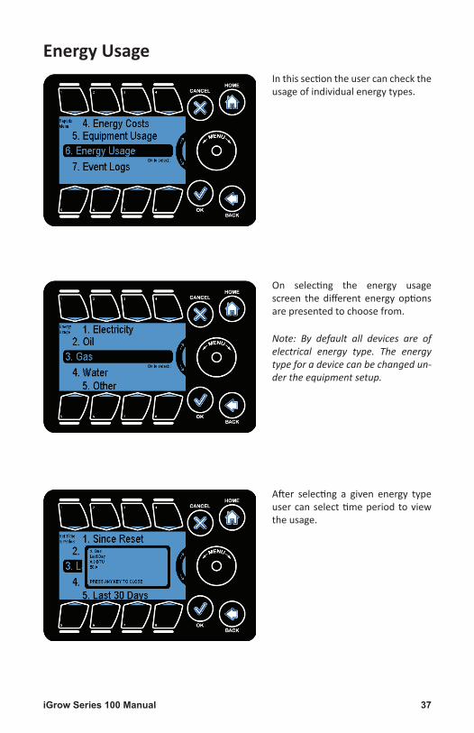
Inthissectiontheusercanchecktheusageofindividualenergytypes.
After selecting a given energy typeusercanselecttimeperiod toviewtheusage.
On selecting the energy usagescreen the different energy optionsarepresentedtochoosefrom.
Note: By default all devices are of electrical energy type. The energy type for a device can be changed un-der the equipment setup.
Energy Usage

iGrow Series 100 Manual38
The event log options allows theuser to view the history of variouseventswhichhappenedoveraperi-odoftimelikestagechanges,sensorerror,relaystatuschanges,etc.
Thefollowingtimeperiodsareavail-able
• SinceReset• Lasthour• Last24Hours• Last7days• Last30days• Thismonth• Thisyear
Onselectingtheeventlogtheuserispresentedwiththetimeperiodstoviewtheevent logsover thatdura-tion.
TohighlightthesuboptionsWheelorButtons #1 - #7 canbeusedtogotothecorre-spondingoptions.PressingOKwillletuserselecttheoptions
Event Logs

39iGrow Series 100 Manual
Onselectingatimeperiodtheeventsfromthattimeonwardsareshown.
Column1:Displaysthetimestampatwhichtheeventoccurred.
Column2:Describestheevent.
Details: elaborates the selectedevent.
PageUp:Allowstheusertomoveupbyapage
PageDown:Allowstheusertoscrolldownbyapage
Note that the wheel can be used to scroll through one event at a time.
The screen allows the user to vieweither all the eventsor just the ex-ceptions(Button #1togglesbetweenGeneral/Exceptions).
Thedefaultviewisthegeneralview,showingalltheevents,includingtheexceptions.
Note that the exceptions are high-lighted in general view.

iGrow Series 100 Manual40
TheSystem Setupisthethirdoptionin the main menu where the usercan setup the equipment at instal-lationtime,aswellasothermiscel-laneousoperations.
PressingOKorButton #3willlettheusertogotosystemsetupsubmenu
The subsections under the systemsetupare:
1. EquipmentSetup2. Save/Restore3. SensorSetup4. Time&DateSetup5. LocationSetup6. EnergyCost7. IPAddressSetup8. MeasurementUnits9. Advanced
TohighlightthesuboptionsWheelorButtons #1 - #8 canbeusedtogotothecorre-spondingoptions.PressingOKwillletuserselecttheoptions
Note that each of these subsections is described in detail in the following pages.
System Setup

41iGrow Series 100 Manual
Thissectionallowsusertosetuptheequipmentonthevariouschannels,settheirtype,assignnames,energytype,etc.
Note: Equipment is programmed in-dividually.
Note: All subsequent screens are ap-plicable to the selected equipment only.
Selectinga channel gets you to theequipmentscreen.Hereyoucan:
SetatimedOverride
Runan Initial Setup (set theequip-ment name, its type, the energytype,etc.)
Assign Stages toeachoftheequip-mentchannels.
On selecting the equipment setup,the various Channels in which theequipment is connected can be se-lected.
Note that these channels correspond to the physical outputs on the unit.
Note: Vents and curtains require two adjacent channels starting with an odd numbered channel.
Equipment Setup

iGrow Series 100 Manual42
Timed override will switch ON orOFF the corresponding equipmentduringthespecifiedtimesetbyuser.
The timed override is provided fortheuser to seteitheradaily recur-ringeventoraonetimeevent.ThiscanbedonebypressingButton #7
Theoverridedurationcanbesetus-ingthisscreenasshown.
Button #1 - #3canbeusedtohigh-lightagivenfieldandthewheelcanbe used tomodify (increment/dec-rementthehighlightedfield.
Backcanbeusedtogototheequip-mentsettings
The start time for the override canbesetusingthisscreen.
Starttimecanbechangedbypress-ingButton #5.
Buttons #1 - #4areusedtohighlighttimeoptions.
Wheel can be used to increase ordecreasethehighlightedvalue.
Note that you can toggle between either a 12 or 24 hour clock using button #7.

43iGrow Series 100 Manual
Before equipment can be utilized,theproperequipmenttypemustbedefined.
User can go to Initial setting (pressButton 3)tosetthenameandtypeofthecorrespondingchannel.
Anoptional,butuseful,stepistoas-signanametotheequipment.ThisnamewillbedisplayedattheMAINstatusscreen.Button #3canbeusedtogosetnameoption.
Button #1canbeusedtogosettypeoption.Therearetwotypesforeachpieceofequipment:
General Type: the kind of equip-ment this output controls. Thereare4availableequipmenttypes(seebelow).
Energy Type:thetypeofenergythisequipmentconsumes(see2screensbelow).
Backbuttonisbeusedtodeletethepresentnamei.e.,Channel1.Then,usercanenterthedesiredname.
This screen is similar to themobilephoneSMSscreen.Toselectagivenalphabet press the required buttonthenumberoftimes= thepositionofthealphabetinthebutton.E.g.totypeCpressButton #1threetimes.Toenternumbersusethewheel.
Note: If the equipment is a dual
Thefigurebelowshowsthescreentosetupthenameoftheequipment.
Underthegeneral/energytypesetupthetypewhichisselectedistheonesurroundedbyparenthesis.TheimageinthefollowingfigureshowsthatOn/Offdeviceisselected.
channel (vent/curtain) device, the name of the second channel (the even channel) is the same as the first (odd) channel.

iGrow Series 100 Manual44
Thegeneralequipmenttypesare:
ON/OFF: Refers to any piece of equip-mentthatturnsonandoffineachoftheheating/cooling/dehum stages. For ex-ample,heater,fan,coolpad,pump,etc.
VENT: Refers to a proportionally con-trolled ventilation equipment, e.g. sidewall,ridgevent.
CURTAIN:Referstoashadingsystem.
ALARM:Usethealarmoutputtoturnan
Inordertochangethetypetosomeothertypelike,fromOn/OfftoVentas shown in the figure, we get awarningpopupasshowninfigure.
Ventsrequires2consecutiveoutputchannels(1&2,3&4,5&6,7&8).Thefirst channel (odd numbered)mustbewiredtoOpenvent,andtheoth-er(evennumbered)toCLOSEit.
To highlight the sub options useWheel or Buttons #1 - #4 corre-sponding to the options andOK toselecttheoptions
BydefaultallequipmentaremarkedasOn/Offdevice.
Ifatypethathasalreadybeencho-sen(i.e.surroundedbyparenthesis)isselectedagain,wegetthisprompt.
outputondependinguponcrossingatemperaturelevel.ThisisnormallyconnectedtoatelephonedialersuchastheSensaphone.
General Type

45iGrow Series 100 Manual
Onselectingaventtheuserneedstodothesetupofthefollowing:
• OpentoClosetime• Overrides
To highlight the sub options usewheelorButtons #1 and #2andOKtoselecttheoptions
ThescreenenablestosettheOpen-CloseDuration.
Buttons (#2, #3, #4) are used tohighlight the fields and the Wheelisusedtoincrementanddecrementthefieldvalues.
Note: To determine the vent open-close time turn the manual toggle switch on and use a clock or stop-watch to time the vent as it goes from its fully closed to open position.
The Vent Open- Close Time is thetime in minutes and seconds thatit takes for thevent togo from fullclosedtofullopenpositionandviceversa.
OnselectingtheSetOpen-CloseDu-ration the following screen comesup.
BypressingButton #1usercantogoSet Open/Close time duration op-tion.

iGrow Series 100 Manual46
Navigating back to the SetupOver-ridesmenu,yougetthisscreen.
These overrides are important forsafeandeffectiveventoperations.
Tohighlight the suboptionsWheelorButtons #1 - #3canbeused.Op-tionscanbeselectedbypressingOK.
Wind Vent Override
Set Vent Open Limit: This is themaximumposition the vent can beopenwhenthewindisatorexceed-ingauser-specifiedspeed.
SetWindSpeedLimit:Thisistheus-er-specifiedwindspeedvaluewhichtriggerstheVentOpenLimit.
Thesevaluescanbechangedbyse-lectingButtons #1 and #2
Rain Vent Open Limit: This is themaximumposition the vent can beopenwhentherainisdetected.
Thevaluecanbechangedbyselect-ingButton #1andtheWheelcanbeusedtomodifythevalue.
Note: The weather station or some of its core components need to be installed to setup these overrides.
Wheelcanbeusedtomodifythevalue

47iGrow Series 100 Manual
Outside Temp Vent Override
Set Vent Open Limit: This is themaximumposition the vent can beopenwhentheoutsidetemperatureisbelowthesettemperaturelimit.
Set Temp Limit: This is the user-specified temperature value whichtriggers the Vent Open Limit whentemperaturedropsbelowsetvalue.
OpenCloseTime:Itisthetimetakenfor the curtain to go from full cov-ered to full uncovered mode andvice versa. By pressing Button #3 usercantogotothisoption.
LightThreshold:Incasealightsen-sor is present , the light thresholdvalue at which the curtain shouldshade/cover.BypressingButton #6 usercantogotothisoption.
ReopenDelayTime: thetimedelay
Thecurtainsarealsoadualchanneldeviceandcanonlybeprogrammedstartingonanoddchannel.
ThecurtaincanbeprogrammedfortheDayandNightmode.Bypress-ingButtons #1, #2usercantogototheseoptions.
The duration for the start of eachmodecanbesetusingSet Start/End Time.UsercanselectthisoptionbypressingButton #5 andthenOK.
ThesevaluescanbechangedbyselectingButtons #1 and #2.Wheelcanbeusedtomod-ifythevalue
afterwhichthecurtaincanagainbeopened.BypressingButton #8 usercantogotothisoption.Wheelcanbeusedtoincreaseordecreasethevalues

iGrow Series 100 Manual48
ShockProtection: Selectinga shockprotection mode helps in openingthe curtain slowly,preventing it toopenallatonceandthuspreventingsuddentemperaturechanges.
PressButton #2 togotonightmodesetupoption.Then,pressButton #6 togotothisoption
Note: Covered % is the amount by which the curtain should be covered.
Anyoneoftheavailable8channelscanbeselectedtobeanalarmout-put.
Set Temperature: This Tab lets youselect the temperature thresholdaboveorbelowwhichthealarmwillbetriggered.
The daymode and the nightmodestarttimecanbesettoanabsolutevalueusing thescreenas shownortoathesunriseandsunsetvalues.
Locationsetupcanbeusedtoinputthecoordinates
PressButton #5andOKtoconfirm.Then user can change the time bypressingButtons #1,#2,#3,#5,#6.
Note: The sunrise and sunset values
BypressingButton #7usercantogoto%coveredoption.Wheelcanbeusedtoincreaseordecreasethevalue
will correctly calculated only if the location coordinates are entered correctly.

49iGrow Series 100 Manual
Toggle Alarm Type: There are twotemperature alarm settings thatcanbeprogrammed. OneisaHightempalarm,theotherisaLowTempalarm.
Pressing Button #1 enables you totoggletheprogrammingscreensbe-tweenthetwooptions.
After selecting low/high options,Button #2willallowusertosettem-perature.Wheel isusedtoincrease
The100Series controllershave thecapability to calculate energy con-sumption. In order to accomplishthis,thetypeofenergyconsumedbytheequipmentmustbeidentified.
There are the 5 energy types cur-rentlysupported.
WaitTime:ThisTabletstosetawaittime before the alarm is triggered.This time can be set from 0 to 99minutes.
Note: If the temperature drops be-low the threshold during the wait time, the clock will be reset to 0.
BypressingButton 3 usercantogotothisoption
ordecreasethevalues
Wheelisusedtoincreaseordecreasethevalues

iGrow Series 100 Manual50
Oncetheenergytypeisselected,theuserwill be prompted to enter therelevantinformationinorderforthecontroller to accurately determinetheenergyconsumptionrate.
It is advised touseaccurate instru-ments (by trained personnels) tomeasure the consumption rate ofthe equipment, since this deter-mines the accuracy of the control-ler’sabilitytodeterminecost.
Theelectricalenergytypesetupcanbedonetoanactualmeasuredval-ueoraroughestimatedvalue.
The type of setup selected is indi-catedbytheparenthesisaroundthetype.
Theestimatedelectricalsetupissetbydefault.
Theenergy typeselected is indicat-edbyparenthesisacrossthetypeasshownforElectricityinthefigure.
For choosing a different typemovethe highlight to the required typeandpressOK.
Bydefaultallenergytypesaresettoelectricity.
UsercancheckthestatusbypressingButton 7foranyenergytype
Energy Type

51iGrow Series 100 Manual
Toenableaprecisemeasuredcalcu-lationoftheelectricalconsumption,selectMeasuredandpressOK.
Note: A confirmation popup comes up indicating the change in setup as shown.
Toenablearough/approximatecal-culation of the electrical consump-tion , theestimatedsetup is select-ed.
TheVoltagePhase,amperes(Amps)andthePowerFactor(PF)valuesareenteredbypressingButtons #1 - #4andusing theWheel tomodify thevalues.
UsingtheabovevaluesthekWvalueiscalculated.

iGrow Series 100 Manual52
The Voltage, HP/kW/Amps, Motorefficiency and operational load val-uesareenteredbypressingButton (#1, #2, #3, #4)andusingtheWheeltomodifythevalues.
The unit of measurement is BTUs/hr.
The value of BTU/hr is entered bypressingtheButton #1andmodify-ingthevaluesbyusingthewheel.
Thedefaultvalueis1BTU/hr.
EnergyType-Oil
ForsettingtheenergytypeasOilthehighlightismovedtotheOiltypebypressingButton #2 or by using thewheelandpressingOK.

53iGrow Series 100 Manual
EnergyType-Gas
For setting the energy type asGas,the highlight is moved to the gastypebypressingButton #3orbyus-ingtheWheelandpressingOK.
EnergyType-Water
ForsettingtheenergytypeasWater,thehighlightismovedtoWatertypebypressingButton #4orbyusingtheWheelandpressingOK.
The unit of measurement is BTUs/hr.
The value of BTU/hr is entered bypressingtheButton #1andmodify-ingthevaluesbyusingtheWheel.
Thedefaultvalueis1BTU/hr.

iGrow Series 100 Manual54
Theunitofmeasurement is gallonsperminute.
The value of Gallon/min is enteredbypressingtheButton #1andmodi-fyingthevaluesbyusingtheWheel.
Thedefaultvalueis1Gallon/min.
The unit of measurement is unitsperhour.
The valueofUnits/hr is enteredbypressingtheButton #1andmodify-ingthevaluesbyusingtheWheel.
Thedefaultvalueis1Unit/min.
EnergyType-Other
ForsettingtheenergytypeasOther,thehighlight ismovedtotheOthertypebypressingButton #5orbyus-ingtheWheelandpressingOK.

55iGrow Series 100 Manual
AssigningofstagescanbedoneforagivenchannelthroughAssign Stagebutton at the Equipment SettingsmenuordirectlythroughtheStaginglineonthemainmenu.
TheStagesettingscansetfor:
• TempStages• Humiditystages
Note: There are 8 temperature stag-es and 4 humidity stages.
Thereare2heating(H1,H2)and6cooling(C1,C2,C3,C4,C5,C6)stages.
Thenormalstage(N)iswhenneitherheatingnorcoolingisrequired.C1istheloweststageofcoolingandC6thehighestwhileH1isthelowestheatingstageandH2isthehighest.
Assign Stages

iGrow Series 100 Manual56
“Channel” stages: This selectional-lowstheusertosetstagingparam-eters on the current channel theyareunder.
“All Equipment” stages: This selec-tionprovidesatablewitheachpieceofequipmentintheleftcolumnandeach stage of heating and coolingacrossthetop.Itgivesaquickover-viewofhowalloftheequipmentfitonthestagingtable.
When choosing to assign individualequipment to a temperature stagethefollowingscreenisshown.
The Select/Deselect button or theOKbuttoncanbeusedtocheck/un-check the theselection for thecur-rentstage.
For Curtains:
Thetemperaturestagesarenotapplicable.
For On/Off Devices:
Unchecked Boxes:MeansdeviceisoffforthatstageChecked Boxes:Meansdeviceisonforthatstage
For Vents:
0%:indicatesthatventisclosedforthatstage99%:indicatestheventisfullyopenforthatstageIntermediate % value:indicatesthepercentageofventopenforthatstage.
Temperature Stages

57iGrow Series 100 Manual
Theusercanquicklysetthetemper-aturestagingoptionsforeverypieceof equipment by selecting the “Allequipment”stagesoptionontheAs-signStagemenu.
Enter this menu by highlighting itusing theWheel orButton #2 andpressingOK.
Thearrowsareusedformovingthehighlight to the desired stage. TheSetup andOK buttons are used toselect or deselect the highlightedstageforadevice.
For On/Off device types all stagesare active i.e. they can selected ordeselected. For Vents, the heatingstagesH2andH1arenotapplicableand the desired percentage of theventpositionissetusingthewheel.
For Curtains:
Thetemperaturestagesarenotapplicable.
For On/Off Devices:
Unchecked Boxes:MeansdeviceisoffforthatstageChecked Boxes:Meansdeviceisonforthatstage
For Vents:
0%:indicatesthatventisclosedforthatstage99%:indicatestheventisfullyopenforthatstageIntermediate % value:indicatesthepercentageofventopenforthatstage.
Note: For dual channel devices (vents/curtains) the second channel is disabled.

iGrow Series 100 Manual58
“Channel” stages: This selectional-lowstheusertosetstagingparam-eters on the current channel theyareunder.
“All Equipment” stages: This selec-tionprovidesatablewitheachpieceofequipmentintheleftcolumnandeach stage of heating and coolingacrossthetop.Itgivesaquickover-viewofhowalloftheequipmentfitonthestagingtable.
When choosing to assign individualequipment to a humidity stage thefollowingscreenisshown.
ThearrowsareusedformovingthehighlightandtheOn/Off/Non Effec-tivebuttonisusedtoselectordese-lectagivenstageforadevice.
Note: If the channel is mapped to a Vent or a Curtain, Button #1 changes contextually.
Humidify:isengagedwhenthehumidityvalueisbelowtheHumidify(Lowhumidity)set-pointvalue.
Dehumidify: isengagedwhenthehumidityvaluegoesabovetheDehumidify(HighHu-midity)setpointvalue.
ColdDe-humidify: isengagedwhentheoutsidetemperaturegoesbelowthethresholdvaluesetinadvancedscreen.
Note: Curtains and Vents are adjusted incrementally (%) using the scroll wheel.
Humidity Stages

59iGrow Series 100 Manual
Theusercanquicklysetthehumid-ity staging options for every pieceof equipment by selecting the “Allequipment”stagesoptionontheAs-signStagemenu.
Enter this menu by highlighting itusing theWheel orButton #2 andpressingOK.
Thearrowsareusedformovingthehighlight to the desired stage. TheSetup andOK buttons are used toselect or deselect the highlightedstageforadevice.
For dual channel devices (vents/curtains),thesecondchannelisdis-abledasshown.
For Curtains:
0%:Curtainis0%covered99%:Curtainsis99%coveredIntermediate %:Percentageofcurtaincovered.No Change:Devicesarenotaffectedinthatstage.
For On Off Devices:
Override Off:IndicatesdeviceisOffinthatstageOverride On:IndicatesdeviceisoninthatstageNo Change:Devicedoesn’thaveanaffectinthatstage.
For Vents:
0%:Indicatesventisfullyclosed.99%:Ventisfullyopen.Intermediate %:%ofventopenNo Change:Devicesarenotaffectedinthatstage.

iGrow Series 100 Manual60
The runtimevaluesareused inROIcalculationsandruntimeaccuracyisimportant foraccuratecostcalcula-tions.
Userwillbepromtedwithyesornooption.UsercanselectanyoptionbyusingWheelandpressingOK.
Note: The runtime is set to 0 if yes is selected.
Note: This can not be undone.
The runtime counter for an equip-ment channel can be reset in themainEquipmentSettingsmenu.
This is useful when a user changesany equipment previously mappedtoachannel.
While in the main Equipment Set-tingsmenu,pressReset Runtime.
Reset Runtime

61iGrow Series 100 Manual
The controller’s settings as well asthe logfiles canbesavedeithertoonboardmemoryoraUSBmemorystick.
Data can also be recalled from thefilesstoredtothecontroller.
On selecting theSave/Restore but-tonandpressingOKwegetamenutochoosefrom.
Save/Restore Config: Store and re-storetheconfigurationfile.
Save Log Files: Save the log file toUSB.
Save & Restore

iGrow Series 100 Manual62
Oncetheuserhasselectedwhatac-tiontheywouldliketoperform,thesystempromptsforadestinationtoperformtheactionto.
Currently supported save/load de-vicesinclude:
• SDCard• USBDrive• SystemMemory
ThisoptionletsyoulabelandstoreyourprogramineithertheinternalmemoryoftheiGrow100SeriescontrolleroraUSBdrive(jumpdrive).
Youmayhaveprogramsfordifferentcropsorfordifferentseasonsoftheyear.Thiswillbeaconvenientwayofstoringyourprogramswiththecapabilitytorestoretheprogramwheneverdesired.
SaveConfiguration:Allowstheusertostorethecontrollersettings/configurationtoon-boardmemory/USB.
Restore Configuration: Allows theuser to restore the configuration storedon theon-boardsystemmemoryorUSB.
DeleteConfiguration:Allowstheusertodeletetheconfigurationfilesstorednsystemmemory/USB.
Buttons 1, 2 or 3areusedtogotothecorrespondingoptions.
WheelisusedtohighlightthedesiredoptionandOKtogotheoption
Save & Restore Configurations

63iGrow Series 100 Manual
Ifagivendrive isnotpresent/con-nected the system gives an errorpopup indicating the same. In casethedriveisbusyapopupindicatingdeviceisbusyisdisplayed.
Once a save/restore option is se-lectedtheuserispromptedtoenterthefilenameinthescreenindicatedbelow.
This screen is similar to themobilephoneSMSscreen.Toselectagivenalphabet press the required buttonthenumberoftimes= thepositionofthealphabetinthebutton.E.g.totypeCpressButton #1threetimes.ToenternumbersusetheWheel.
Note: If a file with the same name already exists it will be overwritten during restore configuration.
Note: All configuration files are stored as .icf files.

iGrow Series 100 Manual64
To save the log file select the SaveLogFilesoptionbyhighlightingitus-ingtheWheelorbypressingButton #2andpressOK.
On selecting the Save History LogFilesapopupindicatingthefilefor-matspop-ups.Logfilescanbesavedineither.xmlor.csvfileformats.
Select a given format using WheelandpressingOK
Currently supported Save Log Fileoptionsinclude:
• SaveHistoryLogFile• SaveEventLogFiles• USBLoggingSetup
Buttons #1, #2 or #3 areusedtogotothecorrespondingoptions.
Save Log Files
65iGrow Series 100 Manual
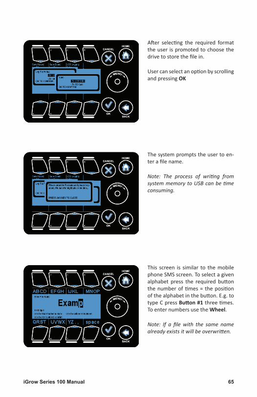
After selecting the required formattheuser ispromotedtochoosethedrivetostorethefilein.
UsercanselectanoptionbyscrollingandpressingOK
This screen is similar to themobilephoneSMSscreen.Toselectagivenalphabet press the required buttonthenumberoftimes= thepositionofthealphabetinthebutton.E.g.totypeCpressButton #1threetimes.ToenternumbersusetheWheel.
Note: If a file with the same name already exists it will be overwritten.
Thesystempromptstheusertoen-terafilename.
Note: The process of writing from system memory to USB can be time consuming.

iGrow Series 100 Manual66
TheSensorSetupmenucanbefoundundertheSystemSetupmenu.
Scroll to the appropriate line usingthe Wheel or quickly navigate bypressingButton #3andthenOK.
TheSensorSetuppageiswheretheusercanmapthesensorthatisusedforinsidetemperaturereadings.
Sensors can also be calibrated andaveragedinthissection.
MapSensors:Thisiswheretheusercansetupthesystemaccordingtothevarioussen-sorsavailable.
CalibrateSensor:Thesensorscanbecalibratedtoadjustforoffsets/softwaresetuphere.
SelfTestSetup:Thisiswherethediagnosticmodetestsetupfordigitalsensorisdone.
AnalogSensorAveraging:Thisoptionallowstheusertoaveragethedatafromseparateanalogsensors.
Buttons #1 - #4 areusedtogotothecorrespondingoptions.
Sensor Setup

67iGrow Series 100 Manual
On selecting a given input you arepresentedwithoptionstomapthatinput to different sensors. You canalsoenable/disablethatsensor.
E.g. if are you are using an analogprobe to measure the inside tem-perature then select analog for In-Temp.Ifyoudon’thaveaparticularsensorselectNone/Disabledforthatsensor.
Themappingoftheinputstothedifferentsensorsisdonehere.Thefigurebelowshowsthedifferentinputsavailableformapping.
InTemp:InsideTemperaturesensor
InHum:InsideHumiditysensor
Light:Lightsensor
OutTemp:Outsidetemperaturesensor
Wind:Winddirectionandspeedsensor
Rain:Rainsensor
Back up Temp:Backuptemperaturesensor
Map Sensors

iGrow Series 100 Manual68
Tocalibrateaninputthesensorisselected.ThePreviousandNextbuttonsareusedtoscrollthroughthedifferentsensors.
RawValue:Thisisthedirectreadingfromthesensor.
CAL:Thisistheoffsetwhichwillbeaddedtorawvaluetogeneratetheadjustedvalue(ADJ).TheWheelcanbeusedtoincreaseanddecreasethevalues.
ADJ:Thisisthevaluewhichwillbereflectedonthestatusscreen.
Calibrate Sensors

69iGrow Series 100 Manual
Thissectionenablestheusertosetupthetestparametersforautomat-ictestingofthedigitaltemperaturesensors.
Ifadigitalsensorispresentandau-tomatictestingofthatsensorisde-sired,mapthesensortooneofthedigital values in the Map Sensorsscreen.
Note: This section only applies to mapped digital sensors.
Set Self Test Time Min Value: Ad-juststhetimeperiodinminutes.
SetSelfTestTimeHrsValue:Adjuststhetimeperiodinhours.
Buttons #2 & #3 are used to go tothe corresponding option. Wheelcanbeusedtoincreaseordecreasethevalues.
Note: In the event that a sensor fails
Enable/Disable Test: Sets the testtoenabledordisabled.Button #1isusedtogotothisoption
SelfTestTime:Thetimeintervalbe-tweenplannedsensortests.
Set Retest Time: The delay afterwhich a test should repeat once aprevioustesthasfailed.Button #4isusedtogotothisoption.
Set Temp Difference: Temperature
the test and no backup sensor is in place, significant crop damage can occur. It is the re-sponsibility of the end user to maintain sensors in good working order.
differencewhichshouldbeseenwhenthetestisinprogress.Button #5 isusedtogotothisoption.
Self Test Set Up

iGrow Series 100 Manual70
Thissectionenablestheusertoaveragethedatafromseparateanalogsensors.
Thisisusefulinsituationswheretheuserneedstotaketemperaturedatafrommultiplelocationsinazoneandaveragethemtoformanaccuratetemperaturereadingfortheentirezone.
UsetheArrowsandWheeltonavigatetoadesiredanalogsensorandmapittobeaver-agedusingtheEnable/DisabletoggleortheOKbutton.
Analog Sensor Mapping

71iGrow Series 100 Manual
This section allows the user tochangethetimeanddatevaluesonthe100Seriescontroller.
Time and Date setupmenu can befoundundersystemsetupmenu
WheelorButton #4 canbeusedtogotohighlightthisoptionandOKtoselectthisoption.
After selecting Time & Date SetuptheusercanchoosetoselecteitherSet TimeorSet Datefromthemenu.
Highlight your choice by using theWheel orButton #1, #2 andpressOK to go to the highlighted selec-tion.
Time & Date Setup

iGrow Series 100 Manual72
Thetimeonthesystemclockcanbeadjustedbyhighlightingachosenfield(Button #1, #2, #3)andusingtheWheeltomodifythefieldvalue.Ifagivenfieldisalreadyhighlightedrepressingthatbuttoncausesthevalueinthatfieldtobeincreased.
12H/24H:Usedtosetthetimedisplayas24hr/12hrduration.
SetHour:Usedtohighlightthehourfield.
SetMin(X0):Usedtohighlightthetensplaceofminutesvalue.
SetMin(0X):Usedtohighlightthesingleplaceofminutesvalue.
AM/PM:UsedtosetAM/PMvalue.
Note that when the clock is set to 24H, the AM/PM button increments the time by 12 hours.
Set Time

73iGrow Series 100 Manual
ThedateonSeries100controllercanbeadjustedbyhighlightingachosenfield(Button #1, #2, #3)andusingtheWheeltomodifythefieldvalue.Ifagivenfieldisalreadyhigh-lightedrepressingthatbuttoncausesthevalueinthatfieldtobeincreased.
ThedateisdisplayedinMM/DD/YYYYformat.
SetMonth:Usedtohighlightthemonthfield.
SetDay:Usedtohighlightthedayfield.
SetYear:Usedtohighlighttheyearfield.
Set Date

iGrow Series 100 Manual74
Location setup allows the user tosetupthelatitudeandlongitudeval-ues.The100Seriescontrollershavean internal astronomical clock andcancalculatetheprecisesunriseandsunsettimesoncethelocationoftheunitisentered.
Location setupmenu can be foundundersystemsetupmenu
Wheel orButton #5canbeusedtogotohighlightthisoptionandOKto
On selecting the edit option, theuserispresentedwiththefollowingscreen.
Forlatitude:“-“:MeansSouth“+“:MeansNorth
Forlongitude:“-”:MeansWest“+”:MeansEast
EDIT LATITUDE: Allows the user toeditthelatitudevalue.
EDITLONGITUDE:Allowstheusertoeditthelongitudevalue.
ValidLocationSetUp:IfsettoFalse,indicatesthatthelatitudeandlongi-tudevaluesareincorrectandshouldbe ignored. If set to true indicatesthat the coordinates are valid/cor-rectandcanbeusedforsunriseandsunsettimecalculations.
selectthisoption
Note that if no sign is indicated it means +
Buttons 5, 6 ,7canbeusedtogotothecorrespondingoptions.
Location Setup

75iGrow Series 100 Manual
This iswhere the energy cost ratesareenteredforeachoftheenergy/watertypes.
Energy Cost setup menu can befoundundersystemsetupmenu
WheelorButton #6canbeusedtogotohighlightthisoptionandOKtoselectthisoption
TheenergycostforElectricityisen-teredaccordingtotheseasons:
• SummerCosts• WinterCosts
Toselectagivenseasonhighlight itusingtheWheelorButtons #1 or #2 andpressOK.
To select a given energy type high-light it using theWheel orButtons #1 through #5andpressOK.
Energy Cost
iGrow Series 100 Manual76
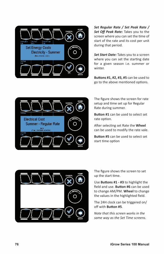
SetRegularRate/SetPeakRate/SetOffPeakRate:Takesyoutothescreenwhereyoucansetthetimeofstartoftherateanditscostperunitduringthatperiod.
SetStartDate:Takesyoutoascreenwhereyoucansetthestartingdatefor a given season i.e. summer orwinter.
Buttons #1, #2, #3, #5canbeusedtogototheabovementionedoptions.
Thefigureshowsthescreentosetupthestarttime.
UseButtons #1 - #3tohighlightthefieldanduse.Button #6canbeusedtochangeAM/PM.Wheeltochangethevaluesinthehighlightedfield.
The24Hclockcanbetriggeredon/offwithButton #5.
Note that this screen works in the same way as the Set Time screens.
ThefigureshowsthescreenforratesetupandtimesetupforRegularRateduringsummer.
Button #1canbeusedtoselectsetrateoption.
AfterselectingsetRatetheWheelcanbeusedtomodifytheratevale.
Button #5canbeusedtoselectsetstarttimeoption

77iGrow Series 100 Manual
ForenergytypesotherthanElectric-itythecostoftheresourceforeachmonthcanbeset.
ThearrowsareusedtoscrollthroughtheselectionsandtheSetupbutton.
OK button can be used to set thevalues.
This figure displays the popupwin-dowwhich came upwhen SetUp ( Buttton #3)/OKbuttonwaspressedtomodifythecostformonthofJan-uary.
The Wheel is used to increase/de-creasetheselectedvalue.

iGrow Series 100 Manual78
The Communication Setup screencan be accessed by navigating ap-propriate line in the System SetupMenu.
Communicationsetupmenucanbefoundundersystemsetupmenu
WheelorButton #7canbeusedtogotohighlightthisoptionandOKtoselectthisoption
The Communication Setup Menuconsists of Weather Station SetupandIPAddressSetup.
Weather Station Setup: Allows theuser to indicatewhetheraweatherstation is directly connected to theunitorthroughanetworkedunit.
IP Address Setup: Allows the usertoconfigurethenetworksettingstoenabletheunitforwebaccess.
Buttons #1, #2 orWheelcanbeusedtohighlighttheoptionandOKisusedtoselecttheoption.
Communication Setup

79iGrow Series 100 Manual
TheWeatherStationSetupmenuisusedtoconfiguretheunittoworkwithaLink4Weath-erStation.
PressingWeather Station Setupcyclesthroughthethreeoptions.
ConnectedDirectly:Theweatherstationiswireddirectlyintothisunit.Selectingthisop-tionalsoenablestheweatherstationdatatobetransmittedtoothernetworked100Se-riescontrollers.
ConnectedviaAnotherUnit:Theweatherstationiswiredintoanother100Seriescontrol-ler.Thatunitcanshareweatherstationdatatothisandanyotherunitthatisnetworkedtoit.
Notpresent/Noneoftheabove:Thereisnoweatherstationdataavailable.
Weather Station Setup

iGrow Series 100 Manual80
TheArrow Buttonsareusedtomovethehighlight.TheEDIT Button( But-ton #4) isused tomodify thehigh-lighteditem.
This figure displays the popupwin-dow which comes up when EDIT Button is pressed. The Wheel canbeusedtoincreaseordecreasethevalue.
TheIPAddresssetupisneededincaseyouneedtoaccesstheunitusingtheweboraPC.
IPAddress:ThisistheaddressthatyouwillenterwhenyoutrytoaccesstheunitusingaPC.ThisaddressmustbeanonconflictingIPaddressandcanbeobtainedfromthenet-workadministrator.
SubnetMask: This canbeobtained from thePCused toaccess theunitor fromyournetworkadministrator.
GatewayAddress:ThiscanbeobtainedfromthePCusedtoaccesstheunitorfromyournetworkadministrator.
MACAddress:ThisistheMACaddressofyourunit.TheMACaddressisuniqueforeachunitandcannotbeedited.
IP Address Setup

81iGrow Series 100 Manual
The units for temperature, windspeed,aswellaslightcanbeadjust-ed under the Measurement UnitssectionoftheSystemSetup.
Scroll the Wheel to the desiredmenuandselectOK.
Theunitscanbechangedbypress-ing thebuttons for thecorrespond-ing measurement (Button #5, #6, #7).
Pressing the buttons toggles theunits.
Temperature:ChooseeitherdegreeFahrenheit(°F)ordegreeCentigrade(°C)
Speed:Chooseeithermilesperhour(Mph)orkilometersperhour(kmph)
Light:ChooseeitherWatts/meter2orklux.
Measurement Units

iGrow Series 100 Manual82
Advancedsettingsforthe100Seriescontroller can be configured undertheAdvancedsectionoftheSystemSetup.
Scroll the Wheel to the desiredmenuandselectOK.
Pressthebuttonforthecorrespond-ingselection(Button #1 - #8)toen-terthedesiredmenu.
HumiditySettings:Usedtosetoutsidetemperatureoverridesettingsforhumiditystages.
ROISettings:UsedtosettheinitialvaluesforReturnonInvestmentcalculations.
ClearAllData:Formatsthedataflashanddeletesallthelogfilesontheunit.
UnitInfo:Givesthegeneralunitdetails.
StageDelay:Usedtosetthedelaybetweenstagechanges.
BeginBootload:Usedforfirmwareupgradeusingbootloader.
Password:Usedtosetuppassword.
UITest:Testthefunctionalityofthetouchsensitiveuserinterface.
Advanced

83iGrow Series 100 Manual
OverrideOnDuration:Thetimefortheoverridetoremainactive
OverrideOffDuration:Thetimeforoverridetoremaininactive/off
Buttons #1 - #4canbeusedtoselectoverrideon/off.Wheelcanbeusedtochangethevalues.
LowOutTemp: If temperature fallsbelow this value, overridewill trig-ger.
Button 5isusedtoselectlowouttempoption.Wheelcanbeusedtochangethevalues.
TheHumiditysettingsareusedtosetupthesystemincasetheoutsidetemperature islow.Thisscreenwillspecifysomeimportantparametersforyourhumiditycontrol.Withthisscreenyouhavetheoptionofcyclingthehumidificationanddehumidificationstages.Forexample,supposethezonehumidityexceedsthehumiditythreshold. Withoutthecyclingoption,yoursystemwillremaininthedehumidificationstageuntilthehumidityfallsbelowthedehumidificationthresholdbyat least2%RH. Insomecases itmaybeimpossibletogetbelowyourhumiditythreshold.Forthesecircumstancesandforothercases,itwouldbehelpfultocycleinandoutofthehumiditycontroloverride.Thisscreengivesyouthecapabilitytodoso.
Theoptionsare:1. SettheoverrideONdurationinminutesandseconds2. SettheoverrideOFFdurationinminutesandseconds3. Setalowtemperaturethreshold.
Thelowtemperaturethresholdistheoutsidetemperaturebelowwhichthedehumidifi-cationstagewillreverttoitsColddehumidificationstate.Forexample,youmaywanttodehumidifybutifit’sverycoldoutside,youmaywanttoturnontheheatinsteadofopenaventandturningonafan.
Thishumiditysettingsoptioncanbeusefulinotherapplicationsevenifyoudonothaveahumiditysensor.Forexample,youmaywanttodomistingcontrolwithaparticularout-put,Youcansetupa“software”humiditysensor,ahumiditytimewindowandthresholdsothatthecyclingwilltakeplaceduringyourselectedtimeperiod.
Humidity Settings

iGrow Series 100 Manual84
ROI SettingsSetInitialAmount:Theinitialcostoftheunitisenteredhere.ThisvalueisusedtocalculatetheReturnonIn-vestmentvalues.
Button #1 can be used to highlighttheoption.
Wheel can be used to increase ordecreasethevalue.
Unit InfoUnit Info: Use this function to dis-play the firmware version numberandtheunitserialnumber.
Button #4 can be used to highlighttheoption.
Note: This is the same screen that loads on unit startup.
Clear All DataClearAllData:Thisfunctionisusedtoformatthesystemmemory(dataflash).
Button #3 can be used to highlighttheoption.
Wheel can be used to toggle be-tweenoptions.
Selectingyesdeletesallthelogfilesandwebfilesstoredontheunit’ssystemmemory.Note: This can not be undone.

85iGrow Series 100 Manual
Stage DelayStageDelay:Thistimesettinginsec-onds is theshortesttimepermittedfor switching between temperaturestages.Atypicalvalueherewouldbe60 to 120 seconds. This parameteris useful in minimizing the cyclingof your equipment. Button #5 canbe used to highlight timing option.Button #1 isusedtohighlightStateDelayOption.TheWheelisusedtoadjustthetimevalues.
Begin BootloadBeginBootload:Thisisusedforfirm-wareupgradeusingthebootloader.
Button #6 can be used to highlightthe option. Wheel can be used totogglebetweenoptions.
Note: Before doing a firmware up-date, a USB with correct binary file much be connected to the system. Tocomeoutfromthismodepress.
Bump Off Time
Button #5 can be used to highlighttimingoption.Button #1 isused tohighlight State Delay Option. TheWheelisusedtoadjustthetimeval-ues.

iGrow Series 100 Manual86
UI TestUI Test: This is a diagnostic modeusedfortestingifthebuttonsonthe100 Series controller are workingcorrectly.Button#8canbeused tohighlight the option.Wheel can beusedtotogglebetweenoptions.
Pressing a given button highlightsit on the screen. the Button #1 through #8oneafteranother.
Password Password:Thisisusedtosetpass-wordfortheuseofcontroller.
Note: Password option is in disabled position and need to to change.
Button #7 can be used to highlighttheoption.ToremovethepassworduserneedtogotopasswordoptionanduseWheel todisable thepass-
word.Ifuserconfirmsthenanewscreenpopsup.Userneedtypeinthepasswordandconfirmit.

87iGrow Series 100 Manual
The lastmain section of the iGrowSeries100™controller istheStagessection.Thissectionprovidesquickaccess to thestagingoptions foundundertheEquipmentSetupmenu.
Note: There are 8 temperature stages and 4 humidity stages.
There are two subsections underStaging:
1. TempStages2. HumidityStages
PLEASEREFERTO“ASSIGNSTAGES”UNDEREQUIPMENTSETUPFORDE-TAILEDINSTRUCTIONSONHOWTOSETUPSTAGING.(page50)
Stages

iGrow Series 100 Manual88
Complete Menu Structure Listing
1. Setpoints
1.1. TempSetpoint
1.1.1. Set–DAY
1.1.1.1. SetHeatSetpoint
TheHeatSetpointisthelowtemperaturetargetbelowwhichtheheatstagesareen-gaged.
1.1.1.2. SetCoolSetpoint
TheCoolSetpointisthehightemperaturetargetabovewhichthecoolingstagesareinvoked.
1.1.1.3. SetStageSeparation
TheStageSeparationisthetemperaturespacingbetweenthestages.Forexample,whenthetemperatureinthezonegoesabovethecoolsetpoint,thesystemwillgointoCool1.IfthetemperaturecontinuestoriseandgoesabovetheCoolSetpoint+theStageSeparationtemperature,thenthesystemwillgointoCool2,andsoforth.
1.1.1.4. SetTime
1.1.1.4.1. SetDAYStartTime
TheDayStartTimeistimewhentheDaySetPointsareengaged.
1.1.1.4.1.1. SunBasedorAbsolute(fixed)
TheStartTimeiseitheranabsolute/fixedtimeorvariesastronomicallybasedonthedaylength.Forthesunbasedoption,thestarttimewilladjusteachdayfromthedatethattheoptionisselected.ThedaylengthisanAstronomicadjustmentbasedonthelatitudeandlongitudeentriesthatyoumade.
1.1.1.5. Advanced
1.1.1.5.1. RampTime
TheRampTimeenablesasmoothtransitionofthetargettemperaturesbetweenthe

89iGrow Series 100 Manual
timeperiods.Iftheramptimeissetto0,therewillbeanimmediatesteptransitioninthesetpointsfromtheprevioustimewindow.Iftheramptimeisnot0,forexample,ifitis30minutes,thenthesetpointswilladjustgraduallyfromonetimeperiodtothenextoverthe30minutetimespan.
1.1.1.5.2. DeadBand
Thisissometimescalled“hysteresisband”.Forcooling,itisthenumberofdegreesthetemperatureneedstodropfromthelowerboundaryofitscurrentstagebeforeitswitchestothelowerstage.(Note:withoutdeadbands,equipmenttendstocyclefre-quentlyandconstantlychangestageswhenthetemperaturereachesthesetpointorastageboundary).Forheating,itisthenumberofdegreesthetemperatureneedstoriseabovethetemperatureboundarybeforeitswitchestoalowerheatingstage.
Typicalvalueswillbe1to2degrees,Fahrenheit.
1.1.2. Set–NIGHT
1.1.2.1. On/Off
ByselectingtheOnoption,youwillbeabletoprogramseparatesetpointsandotherparametersforyourdefinednighttimeperiod.TheOffoptiondisablesthissecondsetofsetpointparameters.
1.1.2.2. SetHeatSetpoint
SamedescriptionasforDay
1.1.2.3. SetCoolSetpoint
SamedescriptionasforDay
1.1.2.4. SetStageSeparation
SamedescriptionasforDay
1.1.2.5. SetTime
1.1.2.5.1. SetNIGHTStartTime
TheNightStartTimeisthetimewhenthenightsetpointsareengaged.
1.1.2.5.1.1. SunBasedorAbsolute
SamedescriptionasforDay
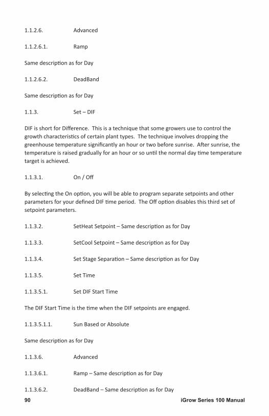
iGrow Series 100 Manual90
1.1.2.6. Advanced
1.1.2.6.1. Ramp
SamedescriptionasforDay
1.1.2.6.2. DeadBand
SamedescriptionasforDay
1.1.3. Set–DIF
DIFisshortforDifference.Thisisatechniquethatsomegrowersusetocontrolthegrowthcharacteristicsofcertainplanttypes.Thetechniqueinvolvesdroppingthegreenhousetemperaturesignificantlyanhourortwobeforesunrise.Aftersunrise,thetemperatureisraisedgraduallyforanhourorsountilthenormaldaytimetemperaturetargetisachieved.
1.1.3.1. On/Off
ByselectingtheOnoption,youwillbeabletoprogramseparatesetpointsandotherparametersforyourdefinedDIFtimeperiod.TheOffoptiondisablesthisthirdsetofsetpointparameters.
1.1.3.2. SetHeatSetpoint–SamedescriptionasforDay
1.1.3.3. SetCoolSetpoint–SamedescriptionasforDay
1.1.3.4. SetStageSeparation–SamedescriptionasforDay
1.1.3.5. SetTime
1.1.3.5.1. SetDIFStartTime
TheDIFStartTimeisthetimewhentheDIFsetpointsareengaged.
1.1.3.5.1.1. SunBasedorAbsolute
SamedescriptionasforDay
1.1.3.6. Advanced
1.1.3.6.1. Ramp–SamedescriptionasforDay
1.1.3.6.2. DeadBand–SamedescriptionasforDay

91iGrow Series 100 Manual
1.2. HumiditySetpoint
1.2.1. Set–DAY
1.2.1.1. SetHumidifySetpoint
TheHumidifySetpointisthelowhumiditytargetbelowwhichthehumidificationstageisengaged.
1.2.1.2. SetDehumidifySetpoint
TheDehumidifySetpointisthehighhumiditytargetabovewhichthedehumidificationstagesareengaged.
1.2.1.3. SetTime
1.2.1.3.1. SetDAYStartTime
ThisisthetimethattheDayHumiditySetpointsareinvoked
1.2.1.3.1.1. SunBasedorAbsolute
Thestarttimeiseitherafixed(absolute)timeoritcanvarydailybasedontheincreaseordecreaseindaylength.ThedaylengthisanAstronomicAdjustmentbasedonthelatitudeandlongitudeentriesthatyoumade.
1.2.1.4. Advanced
1.2.1.4.1. RampTime
TheRampTimeenablesasmoothtransitionbetweenthehumiditytargets.Iftheramptimeissetto0,therewillbeanimmediatesteptransitioninthehumiditysetpointsfromtheprevioustothecurrentsetpointofthefollowingperiod.Iftheramptimeisnotzero,therampingbeginsattheendoftheperiod.
1.2.1.4.2. DeadBand
Forthedehumidificationcase,thisisthehumiditydropbelowthedehumidificationboundarywherethedehumidificationstageterminates.
Forthehumidificationcasethisthehumidityincreaseabovethehumidificationbound-arywherethehumidificationstageterminates.
1.2.2. Set–NIGHT

iGrow Series 100 Manual92
1.2.2.1. On/Off
ThedefaultforthenighthumiditysetpointisOFF.Pressingthetabwillenabletheset-tingofanighttimehumiditysetpoint.
1.2.2.2. SetHumidifySetpoint
Usethescrolltosetthelow(humidity)setpoint.Youcanalsosetitat0.
1.2.2.3. SetDehumidifySetpoint
Pressingthesecondtabfromtheleftonthebottomofthedisplaywillletyousettheupperhumiditysetpoint.Thisisthede-humidificationsetpoint.
1.2.2.4. SetTime
Thisisthetimethatthenightsetpointsareinvoked.
1.2.2.4.1. SetNIGHTStartTime
1.2.2.4.1.1. SunBasedorAbsolute
Thestarttimeiseitherafixed(absolute)timeoritcanvarydailybasedontheincreaseordecreaseindaylength.ThedaylengthisanAstronomicAdjustmentbasedonthelatitudeandlongitudeentriesthatyoumade.
1.2.2.5. Advanced
1.2.2.5.1. Ramp
TheRampTimeenablesasmoothtransitionbetweenthehumiditytargets.Iftheramptimeissetto0,therewillbeanimmediatesteptransitioninthehumiditysetpointsfromtheprevioustothecurrentsetpointofthefollowingperiod.Iftheramptimeisnotzero,therampingbeginsattheendoftheperiod
1.2.2.5.2. DeadBand
Forthedehumidificationcase,thisisthehumiditydropbelowthedehumidificationboundarywherethedehumidificationstageterminates.
Forthehumidificationcasethisthehumidityincreaseabovethehumidificationbound-arywherethehumidificationstageterminates.
1.2.3. Set–DIF

93iGrow Series 100 Manual
DIFisathirdtimewindowina24hourperiodthatyoucanelecttousetocontrolthehumidityseparatelyfromtheothertwoperiods.
1.2.3.1. On/Off
ThedefaultfortheDIFhumiditysetpointisOFF.PressingthetabwillenablethesettingofaDIFtimeperiodhumiditysetpoint.
1.2.3.2. SetHumidifySetpoint
TheHumidifySetpointisthelowhumiditytargetbelowwhichthehumidificationstageisengagedduringtheDIFtimeperiod.
1.2.3.3. SetDehumidifySetpoint
TheDehumidifySetpointisthehighhumiditytargetabovewhichthedehumidificationstagesareengagedduringtheDIFtimeperiod.
1.2.3.4. SetTime
1.2.3.4.1. SetDIFStartTime
1.2.3.4.2.
ThisisthetimethattheDIFsetpointsareinvoked.
1.2.3.4.2.1. SunBasedorAbsolute
Thestarttimeiseitherafixed(absolute)timeoritcanvarydailybasedontheincreaseordecreaseindaylength.ThedaylengthisanAstronomicAdjustmentbasedonthelatitudeandlongitudeentriesthatyoumade.
1.2.3.5. Advanced
1.2.3.5.1. Ramp
TheRampTimeenablesasmoothtransitionbetweenthehumiditytargets.Iftheramptimeissetto0,therewillbeanimmediatesteptransitioninthehumiditysetpointsfromtheprevioustothecurrentsetpointofthefollowingperiod.Iftheramptimeisnotzero,therampingbeginsattheendoftheperiod
1.2.3.5.2. DeadBand
Forthedehumidificationcase,thisisthehumiditydropbelowthedehumidificationboundarywherethedehumidificationstageterminates.

iGrow Series 100 Manual94
Forthehumidificationcasethisthehumidityincreaseabovethehumidificationbound-arywherethehumidificationstageterminates
2. Reports
2.1. Return on Investment
2.2. EquipmentCosts2.2.1. SinceReset2.2.2. LastHour2.2.3. Last24Day2.2.4. Last7Days2.2.5. Last30Days2.2.6. ThisMonth2.2.7. ThisYear
2.3. EnergyCosts2.3.1. SinceReset2.3.2. LastHour2.3.3. Last24Day2.3.4. Last7Days2.3.5. Last30Days2.3.6. ThisMonth2.3.7. ThisYear
2.4. Equipment Usage
2.4.1. Channel12.4.1.1. SinceReset2.4.1.2. LastHour2.4.1.3. Last24Day2.4.1.4. Last7Days2.4.1.5. Last30Days2.4.1.6. ThisMonth2.4.1.7. ThisYear
2.4.2. Channel22.4.2.1. SinceReset2.4.2.2. LastHour2.4.2.3. Last24Day2.4.2.4. Last7Days2.4.2.5. Last30Days2.4.2.6. ThisMonth2.4.2.7. ThisYear
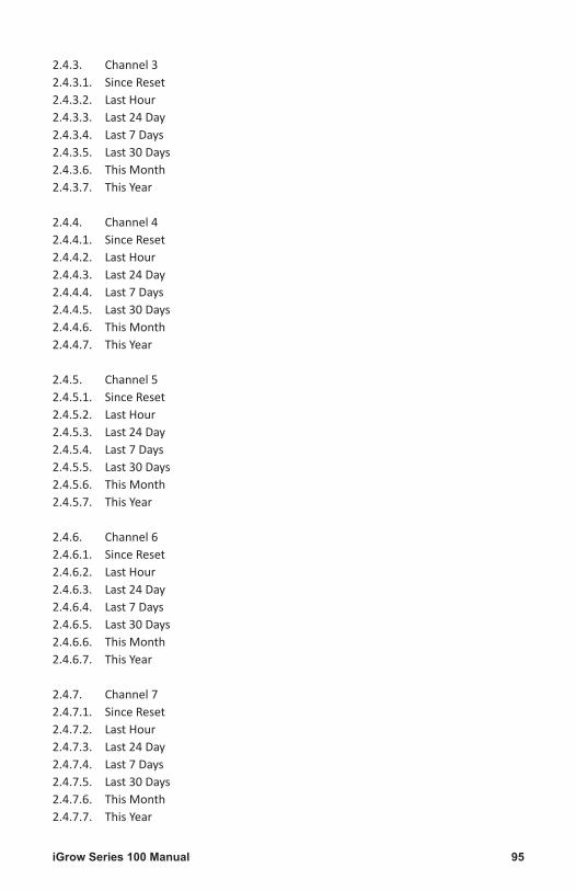
95iGrow Series 100 Manual
2.4.3. Channel32.4.3.1. SinceReset2.4.3.2. LastHour2.4.3.3. Last24Day2.4.3.4. Last7Days2.4.3.5. Last30Days2.4.3.6. ThisMonth2.4.3.7. ThisYear
2.4.4. Channel42.4.4.1. SinceReset2.4.4.2. LastHour2.4.4.3. Last24Day2.4.4.4. Last7Days2.4.4.5. Last30Days2.4.4.6. ThisMonth2.4.4.7. ThisYear
2.4.5. Channel52.4.5.1. SinceReset2.4.5.2. LastHour2.4.5.3. Last24Day2.4.5.4. Last7Days2.4.5.5. Last30Days2.4.5.6. ThisMonth2.4.5.7. ThisYear
2.4.6. Channel62.4.6.1. SinceReset2.4.6.2. LastHour2.4.6.3. Last24Day2.4.6.4. Last7Days2.4.6.5. Last30Days2.4.6.6. ThisMonth2.4.6.7. ThisYear
2.4.7. Channel72.4.7.1. SinceReset2.4.7.2. LastHour2.4.7.3. Last24Day2.4.7.4. Last7Days2.4.7.5. Last30Days2.4.7.6. ThisMonth2.4.7.7. ThisYear

iGrow Series 100 Manual96
2.4.8. Channel82.4.8.1. SinceReset2.4.8.2. LastHour2.4.8.3. Last24Day2.4.8.4. Last7Days2.4.8.5. Last30Days2.4.8.6. ThisMonth2.4.8.7. ThisYear
2.5. Energy Usage
2.5.1. Electricity2.5.1.1. SinceReset2.5.1.2. LastHour2.5.1.3. Last24Day2.5.1.4. Last7Days2.5.1.5. Last30Days2.5.1.6. ThisMonth2.5.1.7. ThisYear
2.5.2. Oil2.5.2.1. SinceReset2.5.2.2. LastHour2.5.2.3. Last24Day2.5.2.4. Last7Days2.5.2.5. Last30Days2.5.2.6. ThisMonth2.5.2.7. ThisYear
2.5.3. Gas2.5.3.1. SinceReset2.5.3.2. LastHour2.5.3.3. Last24Day2.5.3.4. Last7Days2.5.3.5. Last30Days2.5.3.6. ThisMonth2.5.3.7. ThisYear
2.5.4. Water2.5.4.1. SinceReset2.5.4.2. LastHour2.5.4.3. Last24Day2.5.4.4. Last7Days2.5.4.5. Last30Days2.5.4.6. ThisMonth

97iGrow Series 100 Manual
2.5.4.7. ThisYear
2.5.5. Other2.5.5.1. SinceReset2.5.5.2. LastHour2.5.5.3. Last24Day2.5.5.4. Last7Days2.5.5.5. Last30Days2.5.5.6. ThisMonth2.5.5.7. ThisYear
3. System Setup
3.1. Equipment Setup
3.1.1. Channel1
3.1.1.1. Override
Thisfeatureletsyoumanuallyoverrideyourgreenhouseequipmentforspecifiedperi-odsoftime,eitheronceordaily.
3.1.1.1.1. Enable/Disable
Enableletstheoverrideoperate.Disabledisallowstheoverridebutmaintainstheotheruserentries.
3.1.1.1.2. ForceON/OFF
Youcanselectwhetheryouwanttoforce(override)theon/offequipmenteitherOnorOffandtheproportionalequipmentsuchasventsandcurtainstoaparticularpositionbasedonpercentageopenforaventandpercentcoveredforacurtain..
3.1.1.1.3. OverrideDuration
3.1.1.1.3.1. StartTime
Selectthetimeofdayyouwanttheoverridetobegin.
3.1.1.1.3.2. Duration
SelecttheOnorOffoverridetimeinhoursandminutes.
3.1.1.1.3.3. Daily/Onetime
iGrow Series 100 Manual98
If“Daily”isselected,theoverridewilloccureverydayattheStartTime.If“Onetime”isselected,oncetheoverrideiscompleted,itwillnotoccuragainwithoutbeingresettoOn.
3.1.1.2. InitialSettings
Thisiswhereyougoforthefirsttimetodefinethetypeofequipmentoneachchannelthatyouareusingandtonamethechannel.
3.1.1.2.1. SetType
Therearethreetypes(classes)ofequipmentthatyoucanprogram.OneisOn/Offandtheothertwoare“proportional”orVentsandCurtains.
3.1.1.2.1.1. GeneralType
Selectthisoptionwhenyouwanttosetupthechannel
3.1.1.2.1.1.1. On/Off
On/Offequipmentsuchasfans,louvers,heaters,etc.,aresometimesreferredtoasdigi-taloutputs.Thisequipmenttypeoccupiesonlyonechannelandcanbeprogrammedonanychannel.
3.1.1.2.1.1.2. Vent
Aventwithadriveopenanddrivecloserelayrequirestwoconsecutivechannels.Thefirstmustbeanoddnumberandthesecond,itsneighbortotheright,anevennumber.Acceptablepairsare1&2,3&4,5&6and7&8.Theoddnumberedchannelopensthevent,theevennumberclosesthevent.
Aventisaproportionaldevice,sometimesreferredtoasa“timedanalogoutput”.
3.1.1.2.1.1.2.1. OpentoCloseTime
3.1.1.2.1.1.2.1.1. SetOpenTime
The“OpenTime”isthetimeinminutesandsecondsthatittakesfortheventtogofromitsfullclosepositiontofullopenposition.
3.1.1.2.1.1.2.2. SetupOverrides
Thissectionassumesthatyouhaveoutsidesensorssuchasarainsensor,windspeedanddirectionsensorand/oranoutsidetemperaturesensor.Thesearetypicallypartofaweatherstationassemblybutcanbeobtainedseparately.

99iGrow Series 100 Manual
3.1.1.2.1.1.2.2.1. Rain
SetVentOpenLimit–thissetsalimitonthemaximumopenpositionfortheventwhenthesensordetectsrain.
3.1.1.2.1.1.2.2.2. Wind
SetVentOpenLimit
Thisisthemaximumpercentopenfortheventwhenthewindspeedexceedsthelimitsetnext.Theprogramcalculatestheaveragewindspeedoverthelast3seconds.Thisistoeliminaterespondingtoshortwindgusts.
SetWindSpeedLimit
ThisisthewindspeedatwhichtheventwillbeclosedtotheVentOpenLimitpreviouslyprogrammed.Thewindoverrideendswhenthewindspeedfallsbelowthethresholdfortwominutes.
3.1.1.2.1.1.2.2.3. OutsideTemp
Intheeventthatitisverycoldoutsideyoumaywanttolimitthepercentageopeningoftheventregardlessoftheinsidezonetemperature.
SetVentOpenLimit
Thisisthemaximumpercentopenfortheventwhentheoutsidetemperaturefallsbelowthethresholdsetinthenextentry.
SetTempLimit
Thisistheoutsidetemperaturebelowwhichtheventwillnotexceedthemaximumpercentopenassignedinthepreviousentry.
3.1.1.2.1.1.3. Curtain
3.1.1.2.1.1.3.1. SetDayModeLightThreshold
Thisoptionassumesthatyouhavealightsensoreitheroutsideorabovethecurtain.The“LightThreshold”isthelightlevelabovewhichthecurtainwillbecoveredtothepercentagespecifiedinthenextentry.
3.1.1.2.1.1.3.2. SetDayModeCovered%
Thisisthemaximumpositionforclosingthecurtainduringtheday.Thisisparticularly

iGrow Series 100 Manual100
importantifyouaredependentontheridgeventsforcooling.
3.1.1.2.1.1.3.3. SetDayModeStartTime
Thisisthestartingtimewhenthecurtainwillbesubjecttothelightthreshold.Aslongasthelightlevelisbelowthelightthresholdthecurtainwillremainuncovered.
3.1.1.2.1.1.3.4. SetDayModeEndTime
Thisistheendingtimeforthedaymodeofthecurtain.
3.1.1.2.1.1.3.5. SetOpenDelaytime
Thepurposeofthisparameteristothereducethecurtainmovement.Thelightlevelmustbebelowthe“LightThreshold”foratleastthismanyminutesbeforethecurtainwillopen.
3.1.1.2.1.1.3.6. EnableShockProtection
EnablingShockProtectionforcesthecurtaintoopenslowlyinthemorningwhentheoutsidetemperatureisbelowacertainthreshold.Thisistoavoidthein-rushofcoldairthatmaybeabovetheenergycurtain.Inthemorningwhenthecurtainisscheduledtoopenandiftheoutsidetemperatureisbelowdeg,thecurtainwillopeninfoursteps.Itwillopen5%andthenpausefor5minutes.Itwillrepeatthis4timesandthenopento0%withoutstopping.
3.1.1.2.1.1.3.7. SetOpen-CloseTime
Thisisthetimeittakesforthecurtaintogofromitsuncoveredposition0%closedtoitscoveredposition,100%closed.Enterthetimeinminutesandseconds.
3.1.1.2.1.1.4. Alarm
Anyoneoftheavailable8channelscanbeselectedtobeanalarmoutput.Whenanalarmconditionismet,thedigitaloutput(relay)isclosed.
3.1.1.2.1.1.4.1. ToggleAlarmType
Therearetwotemperaturealarmsettingsthatcanbeprogrammed.OneisaHightempalarm,theotherisaLowTempalarm.PressingthetopleftTabenablesyoutotoggletheprogrammingscreensbetweenthetwooptions.
3.1.1.2.1.1.4.2. SetTemperature
ThisTabletsyouselectthetemperaturethresholdaboveorbelowwhichthealarmwill

101iGrow Series 100 Manual
betriggered.
3.1.1.2.1.1.4.3. SetWaitTime
ThisTabletstosetawaittimebeforethealarmistriggered.Thistimecanbesetfrom0to99minutes.Thealarmconditionmustexistduringtheentirewaittimeforthealarmconditiontobemet.Ifthetemperaturedropsbelowthethresholdduringthewaittime,theclockwillberesetto0.
3.1.1.2.1.2. EnergyType
3.1.1.2.1.2.1. Electricity
3.1.1.2.1.2.1.1. Measured3.1.1.2.1.2.1.1.1. Voltage3.1.1.2.1.2.1.1.2. Phase3.1.1.2.1.2.1.1.3. Amps3.1.1.2.1.2.1.1.4. PowerFactor3.1.1.2.1.2.1.1.5. Status
3.1.1.2.1.2.1.2. Estimated3.1.1.2.1.2.1.2.1. Voltage3.1.1.2.1.2.1.2.2. HP/kW/Amps3.1.1.2.1.2.1.2.3. MotorEfficiency3.1.1.2.1.2.1.2.4. OperationalLoad3.1.1.2.1.2.1.2.5. Status
3.1.1.2.1.2.2. Oil
3.1.1.2.1.2.2.1. BTUs/h3.1.1.2.1.2.2.2. Status
3.1.1.2.1.2.3. Gas
3.1.1.2.1.2.3.1. BTUs/h3.1.1.2.1.2.3.2. Status
3.1.1.2.1.2.4. Water
3.1.1.2.1.2.4.1. Gallon/min3.1.1.2.1.2.4.2. Status
3.1.1.2.1.2.5. Other
3.1.1.2.1.2.5.1. Units/h

iGrow Series 100 Manual102
3.1.1.2.1.2.5.2. Status
3.1.1.2.2. SetName
YoucanprogramacustomnameforeachpieceofequipmentconnectedtotheiGrow.Thealphanumericdisplayletsyouentertextmuchlikeyouwouldonacellphone.Youhaveuptonine(9)positionsthatyoucanuse.
3.1.1.3. AssignStage
Selecteitherthetemperaturestagesorthehumiditystages.
3.1.1.3.1. TempStages
3.1.1.3.1.1. 1.“Channel”stages
Thisselectionletsyouprogramtheparticularchannelthatyou’vechosen.
3.1.1.3.1.2. 2.“AllEquipmentStages”
Thisselectiongivesyouatablewitheachpieceofequipmentintheleftcolumnandeachstageofheatingandcoolingacrossthetop.Itgivesaquickoverviewofhowyou’veprogrammedeachpieceofequipment.Italsogivesyoutheoptionofprogramminginasinglelocationanyoralloftheequipmentfortemperaturecontrol.
3.1.1.3.2. HumidityStages
3.1.1.3.2.1. 1.“Channel”stages
Thisselectionletsyouprogramtheparticularchannelthatyou’vechosen.
3.1.1.3.2.2. 2.“AllEquipmentStages”
Thisselectiongivesyouatablewitheachpieceofequipmentintheleftcolumnandeachhumiditystageacrossthetop.Itgivesaquickoverviewofhowyou’vepro-grammedeachpieceofequipment.Italsogivesyoutheoptionofprogramminginasinglelocationanyoralloftheequipmentforhumiditycontrol.
3.1.1.3.2.2.1. Humidify
Whenthezoneshumiditygoesbelowthelowhumiditysetpoint,thisengagesthehu-midityorhumidificationstage.
Equipmentprogrammedatthecontrollercanbeactivatedorde-activated,asdesired,whenthisstageistriggered.AnotheroptionforeachpieceofequipmentisN/A,which

103iGrow Series 100 Manual
meansnoparticularactionistakenwiththatequipmentinthehumidifystage.
3.1.1.3.2.2.2. De-Humidify
Whenthezoneshumiditygoesabovethehighhumiditysetpoint,thisengagesthedehu-midificationstage.
Equipmentprogrammedatthecontrollercanbeactivatedorde-activated,asdesired,whenthisstageistriggered.AnotheroptionforeachpieceofequipmentisN/A,whichmeansnoparticularactionistakenwiththatequipmentinthehumidifystage.
3.1.1.3.2.2.3. De-Humidify(Cold)
Whenthezoneshumiditygoesabovethehighhumiditysetpointandtheoutdoortem-peraturegoesbelowxxdeg,the“ColdDe-humidification”stageisengaged.Equipmentprogrammedatthecontrollercanbeactivatedorde-activated,asdesired,whenthisstageistriggered.AnotheroptionforeachpieceofequipmentisN/A,whichmeansnoparticularactionistakenwiththatequipmentinthisstage.
3.2. Save/Restore
ThisoptionletsyoulabelandstoreyourprogramineithertheinternalmemoryoftheiGrow,toaUSBdrive(jumpdrive),and/oranSDcard.Youmayhaveprogramsfordif-ferentcropsorfordifferentseasonsoftheyear.Thiswillbeaconvenientwayofstoringyourprogramswiththecapabilitytorestoretheprogramwheneverdesired.
3.2.1. SaveConfiguration
PressingtheSaveConfigurationkeywillbringupthesavetooption.Clearly,ifyouaregoingtosavetoaUSBdriveoranSDcardyouwillneedtohaveplacedeitherofthesedevicesinsideyouriGrow.Aftermakingyouselectionyouwillbegiventheoptionoflabelingthefilewithuptoninealphanumeric.
3.2.2. RestoreConfiguration
Pressingthiskeywillbringupthe“restorefrom..”option.Youmustselectoneofthethreeoptionsfromwhichtoextractthefile.Thefileyouselectwillthenreplacetheoneyoucurrentlyareusing.
3.2.3. DeleteConfiguration
Pressingthiskeywillbringupthe“deletefrom”option.Youmustselectoneoftheop-tionsfromwhichtoremovethefile.Thefilewillthenbepermanentlydeleted.
3.3. Sensor Setup
iGrow Series 100 Manual104
3.3.1. MapSensors3.3.2. CalibrateSensors3.3.3. SefTestSetUp3.3.4. AnalogSensorAveraging
3.4. Time & Date Setup
3.4.1. SetTime
Youcansetthecurrenttimeusingthefourtabsatthetopofthescreen.Youalsohavetheoptionofusinga24hourclockbypressingthetabatthebottomofthescreen.
3.4.2. SetDate
Youcansetthedateusingthethreetabsatthetopofthescreen.
3.5. Location Setup
TheiGrow800hasaninternalastronomicalclock.Byknowingtheactualcoordinates,sunriseandsunsettimescanbepreciselycalculated.Gotoheavens-abovetofindcoor-dinatesforyourpreciselocation.Ifanegativelongitudeisgivenyouarewest,andifanegativelatitudeisgivenyouareinthesouthernhemisphere.
3.5.1. EditLatitude
Toedit,presstheappropriatetabatthebottomofthescreen.
3.5.2. EditLongitude
Toedit,presstheappropriatetabatthebottomofthescreen.
3.6. Energy Cost
3.6.1. Electricity3.6.2. Oil3.6.3. Gas3.6.4. Water3.6.5. Other
3.7. Communication Setup
3.7.1. WeatherStationSetup
3.7.2. IPAddressSetup

105iGrow Series 100 Manual
3.7.2.1. IPAddress3.7.2.2. SubnetMask3.7.2.3. GatewayAddress3.7.2.4. MACAddress
3.8. Measurement Units
3.8.1. TempUnits
ThelowerlefthandtabontheMeasureUnitsSetupscreenisusedtotogglebetweentheFahrenheitorCelsiusunitsfortemperature.Everytemperaturereadingdisplayedwillbebasedontheunitsyouselect.
3.8.2. SpeedUnits
ThesecondtabatthebottomofthescreenisusedtotogglebetweenMph(Milesperhour)andkmph(kilometersperhour).
3.8.3. LightUnits
ThethirdtabfromthebottomleftisusedtoselectbetweenWatts/meter-squaredandKilolux(Klux)forlightmeasurements.
3.9. Advanced
3.9.1. UnitInfo
ThistabprovidesimportantinformationregardingyouriGrowunit.Itincludesthemodeltype,theversionnumberandtheserialnumber.
3.9.2. HumiditySettings
Thisscreenwillspecifysomeimportantparametersforyourhumiditycontrol.Withthisscreenyouhavetheoptionofcyclingthehumidificationanddehumidificationstages.Forexample,supposeyourzoneshumidityexceedsthehumiditythreshold.Withoutthecyclingoption,yoursystemwillremaininthedehumidificationstageuntilthehumid-ityfallsbelowthedehumidificationthresholdbyatleast2%RH.Insomecasesitmaybeimpossibletogetbelowyourhumiditythreshold.Forthesecircumstancesandforothercases,itwouldbehelpfultocycleinandoutofthehumiditycontroloverride.Thisscreengivesyouthecapabilitytodoso.
Theoptionsare:
1.SettheoverrideONdurationinminutesandseconds2.SettheoverrideOFFdurationinminutesandseconds
iGrow Series 100 Manual106
3.Setalowtemperaturethreshold.
Thelowtemperaturethresholdistheoutsidetemperaturebelowwhichthedehumidi-ficationstagewillreverttoitsColddehumidificationstate.Forexample,youmaywanttodehumidifybutifit’sverycoldoutside,youmaywanttoturnontheheatinsteadofopenaventandturningonafan.
Thishumiditysettingsoptioncanbeusefulinotherapplicationsevenifyoudonothaveahumiditysensor.Forexample,youmaywanttodomistingcontrolwithaparticularoutput,Youcansetupa“software”humiditysensor,ahumiditytimewindowandthresholdsothatthecyclingwilltakeplaceduringyourselectedtimeperiod.
3.9.3. StageDelay
Thistimesettinginsecondsistheshortesttimepermittedforswitchingbetweentem-peraturestages.Atypicalvalueherewouldbe60to120seconds.Thisparameterisusefulinminimizingthecyclingofyourequipment.
4. Stages
4.1. TempStages
4.1.1. “AllEquipmentStages”
Thisselectiongivesyouatablewitheachpieceofequipmentintheleftcolumnandeachstageofheatingandcoolingacrossthetop.Itgivesaquickoverviewofhowyou’veprogrammedeachpieceofequipment.Italsogivesyoutheoptionofprogramminginasinglelocationanyoralloftheequipmentfortemperaturecontrol.
4.2. HumidityStages
4.2.1. “AllEquipmentStages”
Thisselectiongivesyouatablewitheachpieceofequipmentintheleftcolumnandeachhumiditystageacrossthetop.Itgivesaquickoverviewofhowyou’vepro-grammedeachpieceofequipment.Italsogivesyoutheoptionofprogramminginasinglelocationanyoralloftheequipmentforhumiditycontrol.
4.2.1.1. Humidify
Whenthezoneshumiditygoesbelowthelowhumiditysetpoint,thisengagesthehu-midityorhumidificationstage.
Equipmentprogrammedatthecontrollercanbeactivatedorde-activated,asdesired,

107iGrow Series 100 Manual
whenthisstageistriggered.AnotheroptionforeachpieceofequipmentisN/A,whichmeansnoparticularactionistakenwiththatequipmentinthehumidifystage.
4.2.1.2. De-Humidify
Whenthezoneshumiditygoesabovethehighhumiditysetpoint,thisengagesthedehu-midificationstage.
Equipmentprogrammedatthecontrollercanbeactivatedorde-activated,asdesired,whenthisstageistriggered.AnotheroptionforeachpieceofequipmentisN/A,whichmeansnoparticularactionistakenwiththatequipmentinthehumidifystage.
4.2.1.3. De-Humidify(Cold)
Whenthezoneshumiditygoesabovethehighhumiditysetpointandtheoutdoortem-peraturegoesbelowxxdeg,the“ColdDe-humidification”stageisengaged.Equipmentprogrammedatthecontrollercanbeactivatedorde-activated,asdesired,whenthisstageistriggered.AnotheroptionforeachpieceofequipmentisN/A,whichmeansnoparticularactionistakenwiththatequipmentinthisstage.

22725 La Palma Avenue, Yorba Linda, CA 92887 USA P: 866.755.5465 F: [email protected] ● 960-1001-04 ● www.link4corp.com
Copyright © 2012 Link4 Corporation. All Rights Reserved
Delivering Confidence ThroughIntelligent Environmental Controls and Automation Solutions

iGrow Series 100 Manual108
Resetting the ControllerHardReset-Intheeventthatyouneedtoperformareset,openupthefrontdoorandlocatetheREDpushbuttonswitchontherighthandside.Pressingthisbrieflywillresetthecontroller.Thisisasafeoperationandwillnotcauseyoutoloseanyprogrammingorconfigurations.
FactoryDefaultReset-ifeverwanted,orisnecessary,youcanresettheiGrowSeries100TMtoitsfactorydefaultsettings.Todothis,unplugthecontroller,removethebat-teryfor30seconds,thenreinsertthebatterybackintotheholder.Applypower.Afterdoingso,thecontrollerwillsay“iGrowSeries100RestoringDefaultConfigurations………”ItissuggestedthatyouuseaUSBsticktosaveyourconfigurationsbeforemakingafac-torydefaultreset.Then,youcanuseittoquicklyrestoreallyoursettings.
WARNING: This process will erase all of your programmed settings. This can not be undone.