ignition system - shoarmateam · on–vehicle inspection spark test check that spark occurs (a)...
TRANSCRIPT

IGNITION SYSTEM
IG–1
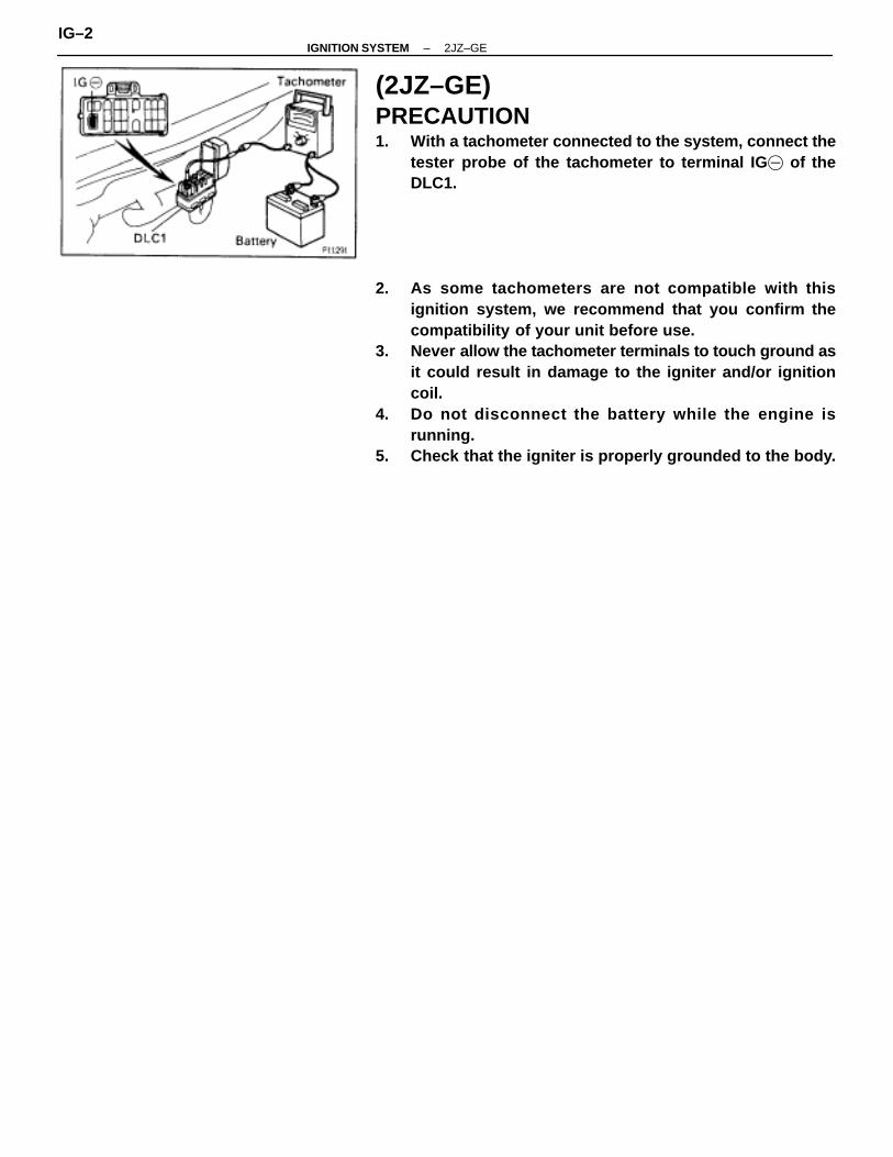
(2JZ–GE)PRECAUTION1. With a tachometer connected to the system, connect the
tester probe of the tachometer to terminal IG � of theDLC1.
2. As some tachometers are not compatible with thisignition system, we recommend that you confirm thecompatibility of your unit before use.
3. Never allow the tachometer terminals to touch ground asit could result in damage to the igniter and/or ignitioncoil.
4. Do not disconnect the battery while the engine isrunning.
5. Check that the igniter is properly grounded to the body.
IG–2–IGNITION SYSTEM 2JZ–GE

PREPARATIONSST (SPECIAL SERVICE TOOLS)
09240–00020 Wire Gauge Set Distributor
RECOMMENDED TOOLS09082–00050 TOYOTA Electrical Tester Set
�
09200–00010 Engine Adjust Kit �
EQUIPMENT
ÑÑÑÑÑÑÑÑÑÑÑÑÑÑÑÑÑÑÑÑÑÑÑÑÑÑÑÑÑÑÑÑÑÑÑÑÑÑÑÑÑÑÑÑÑÑÑÑÑÑ
Megger insulation resistance meter ÑÑÑÑÑÑÑÑÑÑÑÑÑÑÑÑÑÑÑÑÑÑÑÑ
Spark plug
ÑÑÑÑÑÑÑÑÑÑÑÑÑÑÑÑÑÑÑÑÑÑÑÑÑÑÑÑÑÑÑÑÑÑÑÑÑÑÑÑÑÑÑÑÑÑÑÑÑÑ
Spark plug cleaner ÑÑÑÑÑÑÑÑÑÑÑÑÑÑÑÑÑÑÑÑÑÑÑÑÑÑÑÑÑÑÑÑÑÑÑÑÑÑÑÑÑÑÑÑÑÑÑÑÑ
ÑÑÑÑÑÑÑÑÑÑÑÑÑÑÑÑÑÑÑÑÑÑÑÑÑThermometer ÑÑÑÑÑÑÑÑÑÑÑÑ
ÑÑÑÑÑÑÑÑÑÑÑÑCOOLANTÑÑÑÑÑÑÑÑÑÑÑÑÑÑÑÑÑÑÑÑÑÑÑÑÑÑ
Item ÑÑÑÑÑÑÑÑÑÑÑÑÑÑÑÑÑÑÑÑÑÑÑÑ
Capacity ÑÑÑÑÑÑÑÑÑÑÑÑÑÑÑÑÑÑÑÑÑÑÑÑÑÑ
ClassificationÑÑÑÑÑÑÑÑÑÑÑÑÑÑÑÑÑÑÑÑÑÑÑÑÑÑÑÑÑÑÑÑÑÑÑÑÑÑÑ
Engine coolant (W/Heater) M/T A/T
ÑÑÑÑÑÑÑÑÑÑÑÑÑÑÑÑÑÑÑÑÑÑÑÑÑÑÑÑÑÑÑÑÑÑÑÑ
7.3 liters (7.7 US qts, 6.4 lmp. qts)8.3 liters (8.8 US qts, 7.3 lmp. qts)
ÑÑÑÑÑÑÑÑÑÑÑÑÑÑÑÑÑÑÑÑÑÑÑÑÑÑÑÑÑÑÑÑÑÑÑÑÑÑÑ
Ethylene–glycol base
–IGNITION SYSTEM 2JZ–GEIG–3
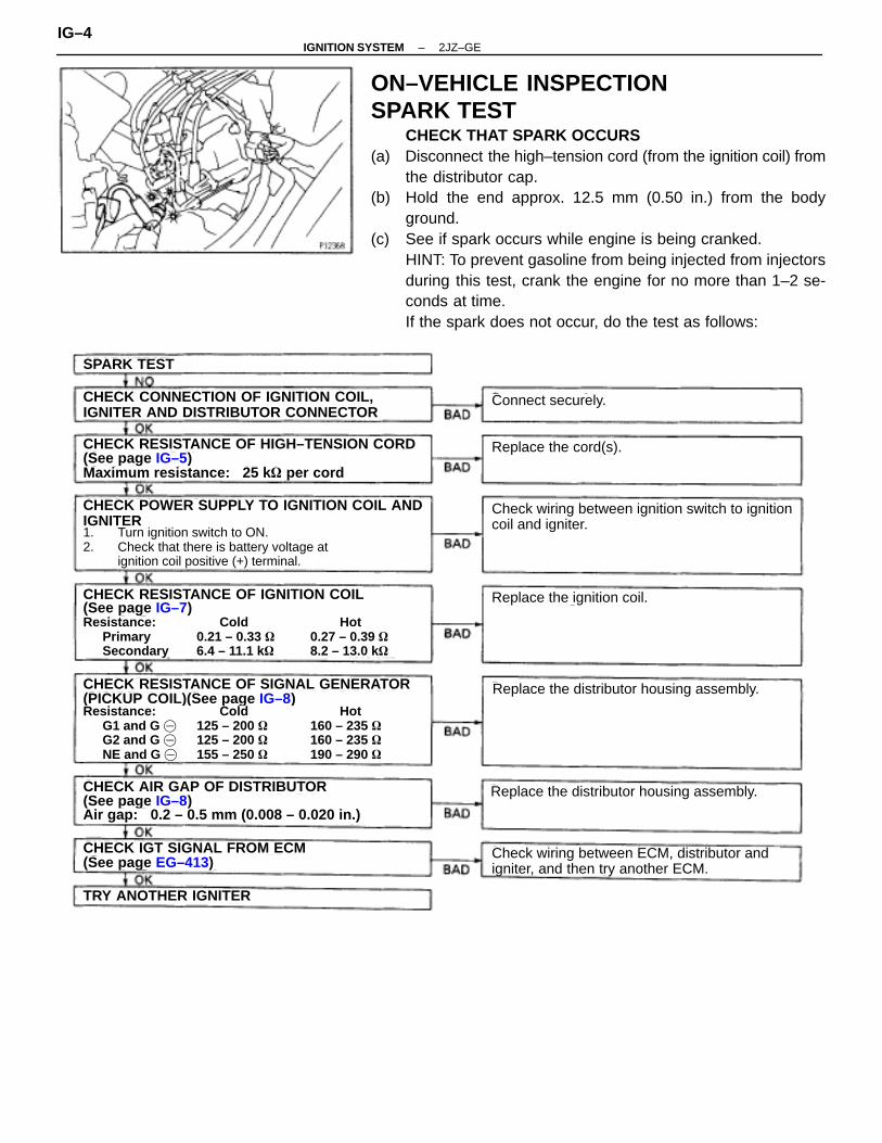
ON–VEHICLE INSPECTIONSPARK TEST
CHECK THAT SPARK OCCURS(a) Disconnect the high–tension cord (from the ignition coil) from
the distributor cap.(b) Hold the end approx. 12.5 mm (0.50 in.) from the body
ground.(c) See if spark occurs while engine is being cranked.
HINT: To prevent gasoline from being injected from injectorsduring this test, crank the engine for no more than 1–2 se-conds at time.If the spark does not occur, do the test as follows:
SPARK TEST
Connect securely.CHECK CONNECTION OF IGNITION COIL,IGNITER AND DISTRIBUTOR CONNECTOR
CHECK RESISTANCE OF HIGH–TENSION CORD(See page IG–5)Maximum resistance: 25 k � per cord
CHECK POWER SUPPLY TO IGNITION COIL ANDIGNITER1. Turn ignition switch to ON.2. Check that there is battery voltage at
ignition coil positive (+) terminal.
CHECK RESISTANCE OF IGNITION COIL(See page IG–7)Resistance: Cold Hot
Primary 0.21 – 0.33 � 0.27 – 0.39 �Secondary 6.4 – 11.1 k � 8.2 – 13.0 k�
CHECK RESISTANCE OF SIGNAL GENERATOR(PICKUP COIL)(See page IG–8)Resistance: Cold Hot
G1 and G � 125 – 200 � 160 – 235 �G2 and G � 125 – 200 � 160 – 235 �NE and G � 155 – 250 � 190 – 290 �
CHECK AIR GAP OF DISTRIBUTOR(See page IG–8)Air gap: 0.2 – 0.5 mm (0.008 – 0.020 in.)
(See page EG–413)CHECK IGT SIGNAL FROM ECM
TRY ANOTHER IGNITER
Replace the cord(s).
Check wiring between ignition switch to ignitioncoil and igniter.
Replace the ignition coil.
Replace the distributor housing assembly.
Replace the distributor housing assembly.
Check wiring between ECM, distributor andigniter, and then try another ECM.
IG–4–IGNITION SYSTEM 2JZ–GE
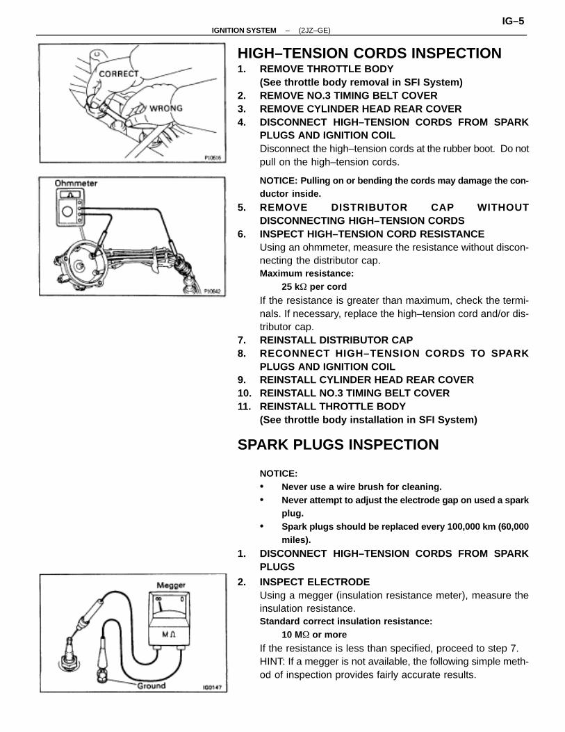
HIGH–TENSION CORDS INSPECTION1. REMOVE THROTTLE BODY
(See throttle body removal in SFI System)2. REMOVE NO.3 TIMING BELT COVER3. REMOVE CYLINDER HEAD REAR COVER4. DISCONNECT HIGH–TENSION CORDS FROM SPARK
PLUGS AND IGNITION COILDisconnect the high–tension cords at the rubber boot. Do notpull on the high–tension cords.
NOTICE: Pulling on or bending the cords may damage the con-ductor inside.
5. REMOVE DISTRIBUTOR CAP WITHOUTDISCONNECTING HIGH–TENSION CORDS
6. INSPECT HIGH–TENSION CORD RESISTANCEUsing an ohmmeter, measure the resistance without discon-necting the distributor cap.Maximum resistance:
25 k� per cord
If the resistance is greater than maximum, check the termi-nals. If necessary, replace the high–tension cord and/or dis-tributor cap.
7. REINSTALL DISTRIBUTOR CAP8. RECONNECT HIGH–TENSION CORDS TO SPARK
PLUGS AND IGNITION COIL9. REINSTALL CYLINDER HEAD REAR COVER10. REINSTALL NO.3 TIMING BELT COVER11. REINSTALL THROTTLE BODY
(See throttle body installation in SFI System)
SPARK PLUGS INSPECTION
NOTICE:• Never use a wire brush for cleaning.• Never attempt to adjust the electrode gap on used a spark
plug.• Spark plugs should be replaced every 100,000 km (60,000
miles).
1. DISCONNECT HIGH–TENSION CORDS FROM SPARKPLUGS
2. INSPECT ELECTRODEUsing a megger (insulation resistance meter), measure theinsulation resistance.Standard correct insulation resistance:
10 M� or more
If the resistance is less than specified, proceed to step 7.HINT: If a megger is not available, the following simple meth-od of inspection provides fairly accurate results.
–IGNITION SYSTEM (2JZ–GE)IG–5
Simple Method:(a) Quickly race the engine 5 times to 4,000 rpm.(b) Remove the spark plug.(c) Visually check the spark plug.
If the electrode is dry...OKIf the electrode is wet...Proceed to step 4
(d) Reinstall the spark plug.3. REMOVE SPARK PLUGS
Using a 16 mm plug wrench, remove the 6 spark plugs.4. VISUALLY INSPECT SPARK PLUGS
Check the spark plug for thread damage and insulator dam-age.If abnormal, replace the spark plug.Recommended spark plug:
NDPK16R11
NGKBKR5EP11
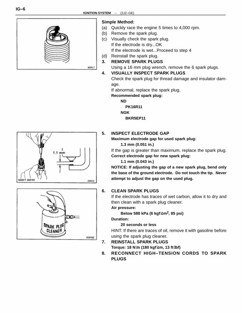
5. INSPECT ELECTRODE GAPMaximum electrode gap for used spark plug:
1.3 mm (0.051 in.)
If the gap is greater than maximum, replace the spark plug.Correct electrode gap for new spark plug:
1.1 mm (0.043 in.)NOTICE: If adjusting the gap of a new spark plug, bend onlythe base of the ground electrode. Do not touch the tip. Neverattempt to adjust the gap on the used plug.
6. CLEAN SPARK PLUGSIf the electrode has traces of wet carbon, allow it to dry andthen clean with a spark plug cleaner.Air pressure:
Below 588 kPa (6 kgf ⋅cm2, 85 psi)Duration:
20 seconds or less
HINT: If there are traces of oil, remove it with gasoline beforeusing the spark plug cleaner.
7. REINSTALL SPARK PLUGSTorque: 18 N ⋅m (180 kgf ⋅cm, 13 ft ⋅lbf)
8. RECONNECT HIGH–TENSION CORDS TO SPARKPLUGS
IG–6–IGNITION SYSTEM (2JZ–GE)
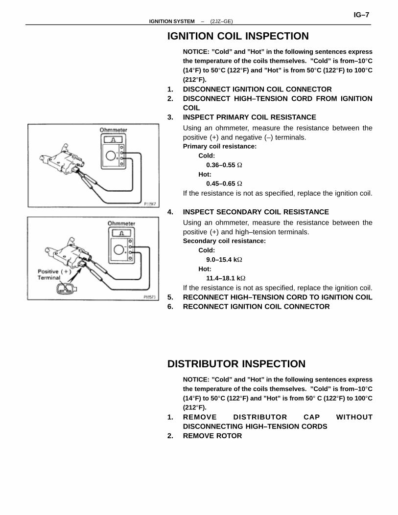
IGNITION COIL INSPECTIONNOTICE: ”Cold” and ”Hot” in the following sentences expressthe temperature of the coils themselves. ”Cold” is from–10 °C(14°F) to 50°C (122°F) and ”Hot” is from 50 °C (122°F) to 100°C(212°F).
1. DISCONNECT IGNITION COIL CONNECTOR2. DISCONNECT HIGH–TENSION CORD FROM IGNITION
COIL3. INSPECT PRIMARY COIL RESISTANCE
Using an ohmmeter, measure the resistance between thepositive (+) and negative (–) terminals.Primary coil resistance:
Cold:0.36–0.55 �
Hot:0.45–0.65 �
If the resistance is not as specified, replace the ignition coil.
4. INSPECT SECONDARY COIL RESISTANCEUsing an ohmmeter, measure the resistance between thepositive (+) and high–tension terminals.Secondary coil resistance:
Cold:9.0–15.4 k�
Hot:11.4–18.1 k�
If the resistance is not as specified, replace the ignition coil.5. RECONNECT HIGH–TENSION CORD TO IGNITION COIL6. RECONNECT IGNITION COIL CONNECTOR
DISTRIBUTOR INSPECTIONNOTICE: ”Cold” and ”Hot” in the following sentences expressthe temperature of the coils themselves. ”Cold” is from–10 °C(14°F) to 50°C (122°F) and ”Hot” is from 50 ° C (122°F) to 100°C(212°F).
1. REMOVE DISTRIBUTOR CAP WITHOUTDISCONNECTING HIGH–TENSION CORDS
2. REMOVE ROTOR
–IGNITION SYSTEM (2JZ–GE)IG–7

3. INSPECT AIR GAPUsing SST (G1 and G2 pickups) and a feeler gauge (NE pick-up), measure the air gap between the signal rotor and pickupcoil projection.SST 09240–00020 for G1 and G2 pickupsAir gap:
0.2–0.5 mm (0.008–0.020 in.)
If the air gap is not as specified, replace the distributor hous-ing assembly.
4. DISCONNECT DISTRIBUTOR CONNECTOR
5. INSPECT SIGNAL GENERATOR (PI CKUP COIL)RESISTANCEUsing an ohmmeter, measure the resistance between termi-nals.Pickup coil resistance:
ColdG1 and G�
125 – 200 �G2 and G�
125 – 200 �NE and G�
155 – 250 �Hot
G1 and G�
160 – 235 �G2 and G�
160 – 235 �NE and G�
190 – 290 �
If the resistance is not as specified, replace the distributorhousing assembly.
6. RECONNECT DISTRIBUTOR CONNECTOR7. REINSTALL ROTOR8. REINSTALL DISTRIBUTOR CAP
IGNITER INSPECTION(See procedure Spark Test on page IG–4)
IG–8–IGNITION SYSTEM (2JZ–GE)

HIGH–TENSION CORD AND CORDCLAMPCOMPONENTS FOR REMOVAL ANDINSTALLATION
–IGNITION SYSTEM 2JZ–GEIG–9
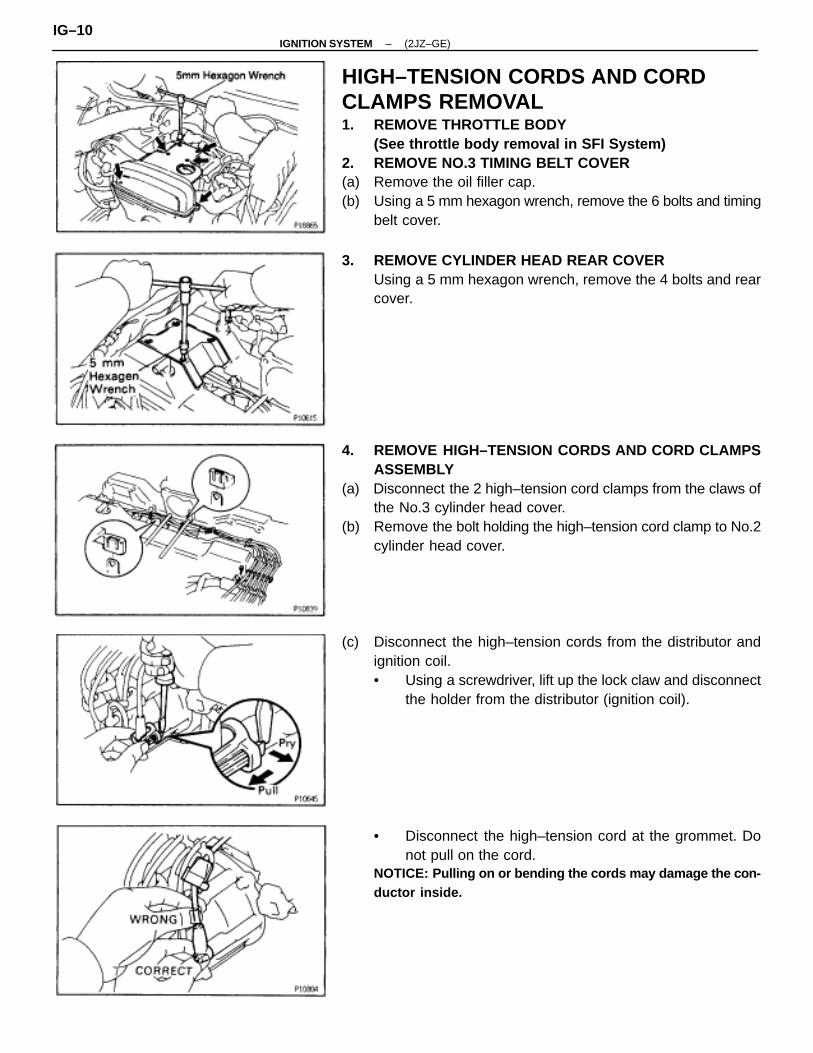
HIGH–TENSION CORDS AND CORDCLAMPS REMOVAL1. REMOVE THROTTLE BODY
(See throttle body removal in SFI System)2. REMOVE NO.3 TIMING BELT COVER(a) Remove the oil filler cap.(b) Using a 5 mm hexagon wrench, remove the 6 bolts and timing
belt cover.
3. REMOVE CYLINDER HEAD REAR COVERUsing a 5 mm hexagon wrench, remove the 4 bolts and rearcover.
4. REMOVE HIGH–TENSION CORDS AND CORD CLAMPSASSEMBLY
(a) Disconnect the 2 high–tension cord clamps from the claws ofthe No.3 cylinder head cover.
(b) Remove the bolt holding the high–tension cord clamp to No.2cylinder head cover.
(c) Disconnect the high–tension cords from the distributor andignition coil.• Using a screwdriver, lift up the lock claw and disconnect
the holder from the distributor (ignition coil).
• Disconnect the high–tension cord at the grommet. Donot pull on the cord.
NOTICE: Pulling on or bending the cords may damage the con-ductor inside.
IG–10–IGNITION SYSTEM (2JZ–GE)
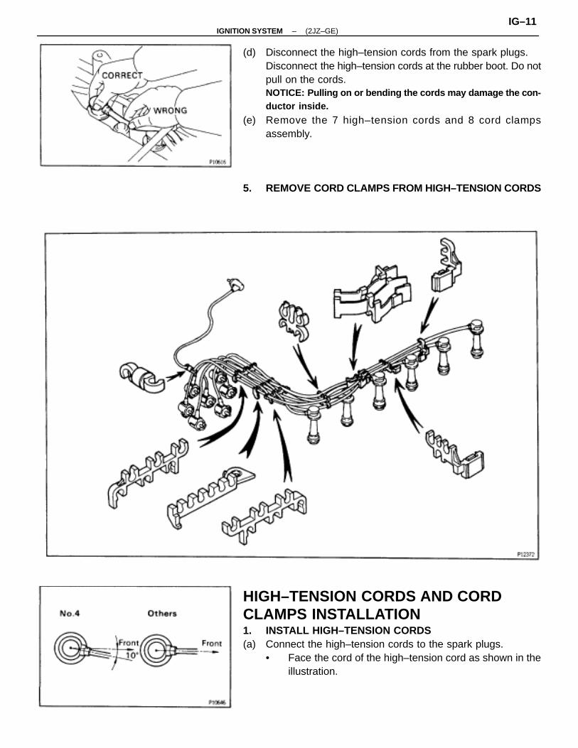
(d) Disconnect the high–tension cords from the spark plugs.Disconnect the high–tension cords at the rubber boot. Do notpull on the cords.NOTICE: Pulling on or bending the cords may damage the con-ductor inside.
(e) Remove the 7 high–tension cords and 8 cord clampsassembly.
5. REMOVE CORD CLAMPS FROM HIGH–TENSION CORDS
HIGH–TENSION CORDS AND CORDCLAMPS INSTALLATION1. INSTALL HIGH–TENSION CORDS(a) Connect the high–tension cords to the spark plugs.
• Face the cord of the high–tension cord as shown in theillustration.
–IGNITION SYSTEM (2JZ–GE)IG–11
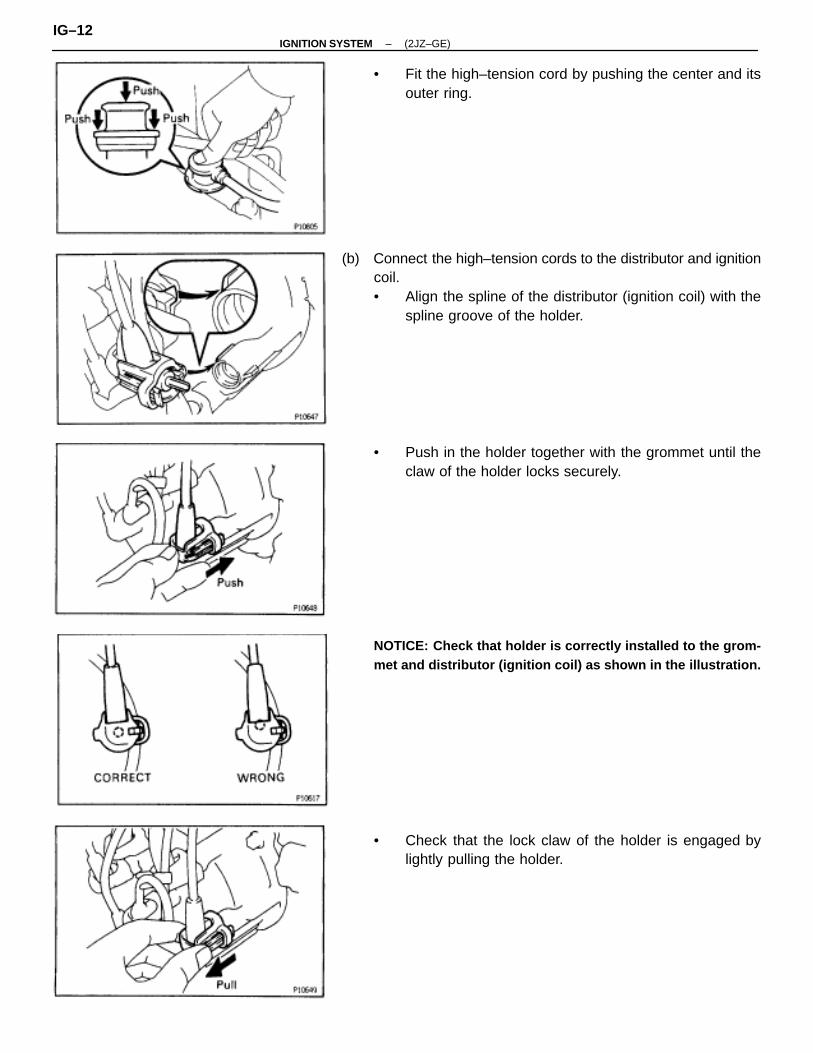
• Fit the high–tension cord by pushing the center and itsouter ring.
(b) Connect the high–tension cords to the distributor and ignitioncoil.• Align the spline of the distributor (ignition coil) with the
spline groove of the holder.
• Push in the holder together with the grommet until theclaw of the holder locks securely.
NOTICE: Check that holder is correctly installed to the grom-met and distributor (ignition coil) as shown in the illustration.
• Check that the lock claw of the holder is engaged bylightly pulling the holder.
IG–12–IGNITION SYSTEM (2JZ–GE)
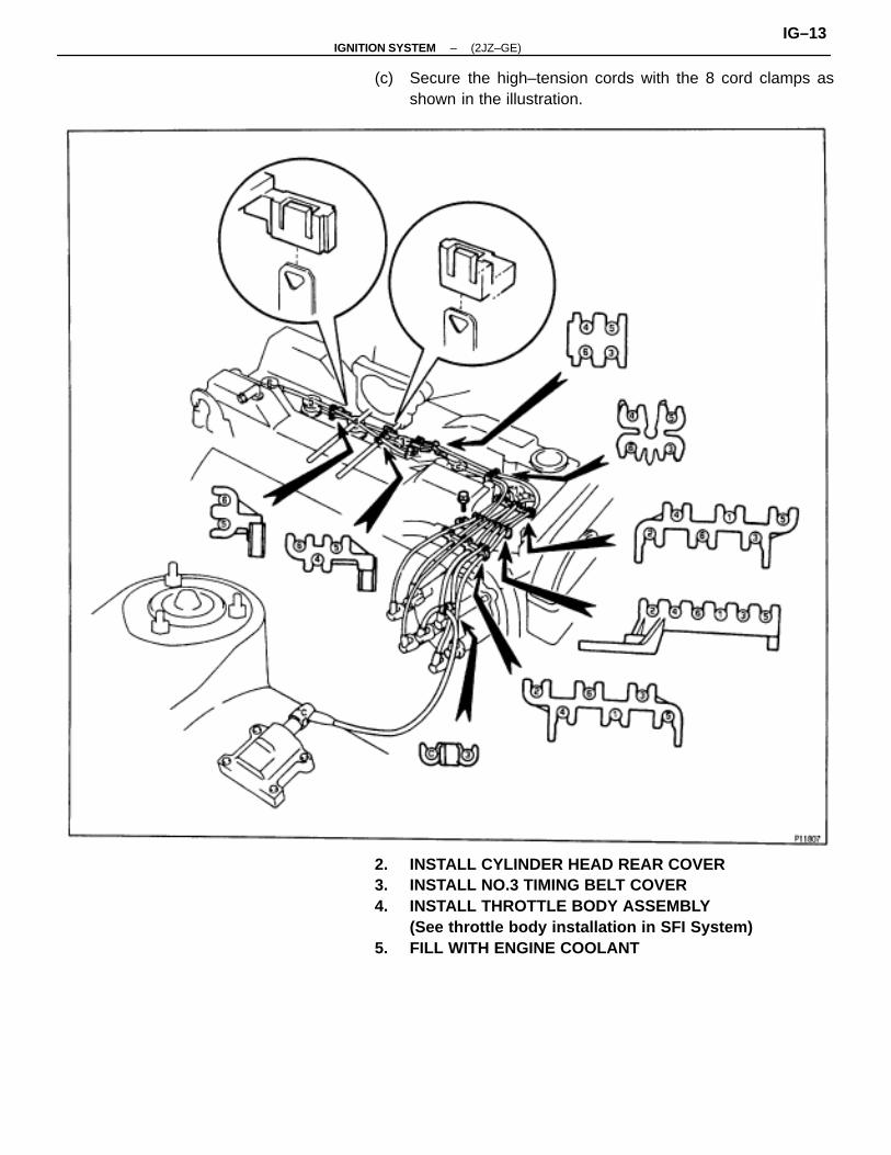
(c) Secure the high–tension cords with the 8 cord clamps asshown in the illustration.
2. INSTALL CYLINDER HEAD REAR COVER3. INSTALL NO.3 TIMING BELT COVER4. INSTALL THROTTLE BODY ASSEMBLY
(See throttle body installation in SFI System)5. FILL WITH ENGINE COOLANT
–IGNITION SYSTEM (2JZ–GE)IG–13
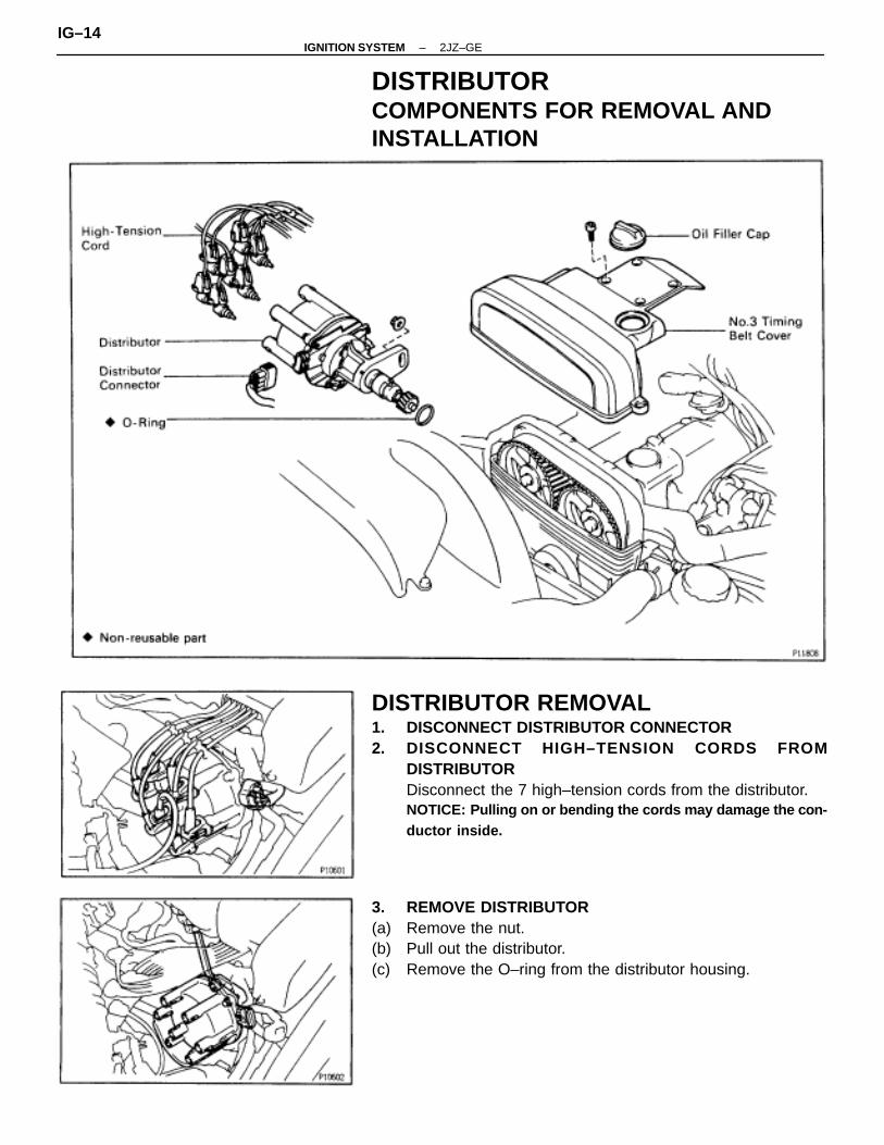
DISTRIBUTORCOMPONENTS FOR REMOVAL ANDINSTALLATION
DISTRIBUTOR REMOVAL1. DISCONNECT DISTRIBUTOR CONNECTOR2. DISCONNECT HIGH–TENSION CORDS FROM
DISTRIBUTORDisconnect the 7 high–tension cords from the distributor.NOTICE: Pulling on or bending the cords may damage the con-ductor inside.
3. REMOVE DISTRIBUTOR(a) Remove the nut.(b) Pull out the distributor.(c) Remove the O–ring from the distributor housing.
IG–14–IGNITION SYSTEM 2JZ–GE
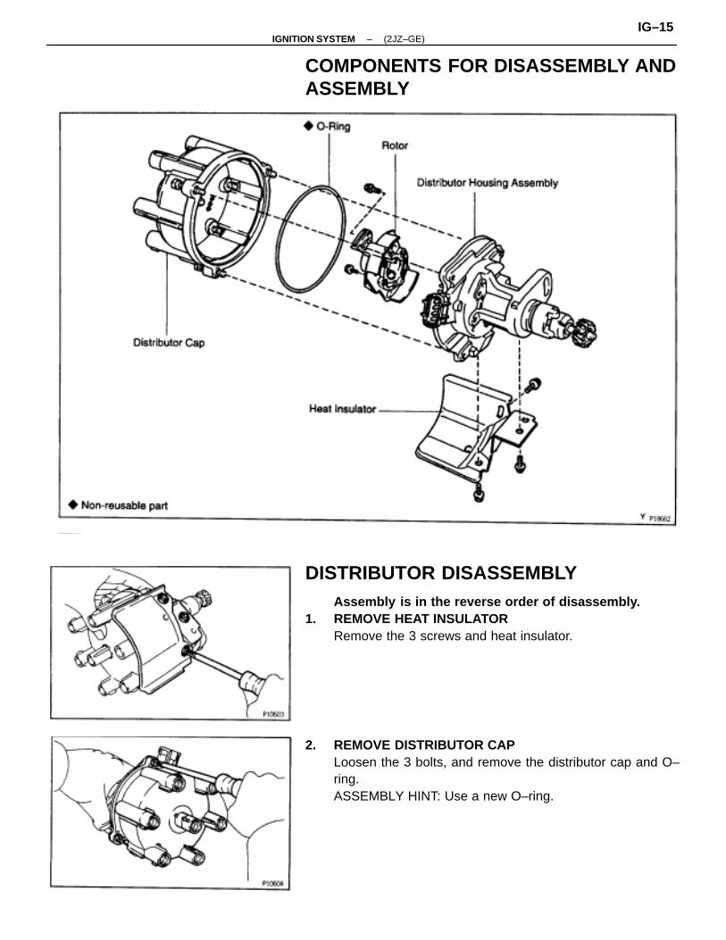
COMPONENTS FOR DISASSEMBLY ANDASSEMBLY
DISTRIBUTOR DISASSEMBLYAssembly is in the reverse order of disassembly.
1. REMOVE HEAT INSULATORRemove the 3 screws and heat insulator.
2. REMOVE DISTRIBUTOR CAPLoosen the 3 bolts, and remove the distributor cap and O–ring.ASSEMBLY HINT: Use a new O–ring.
–IGNITION SYSTEM (2JZ–GE)IG–15
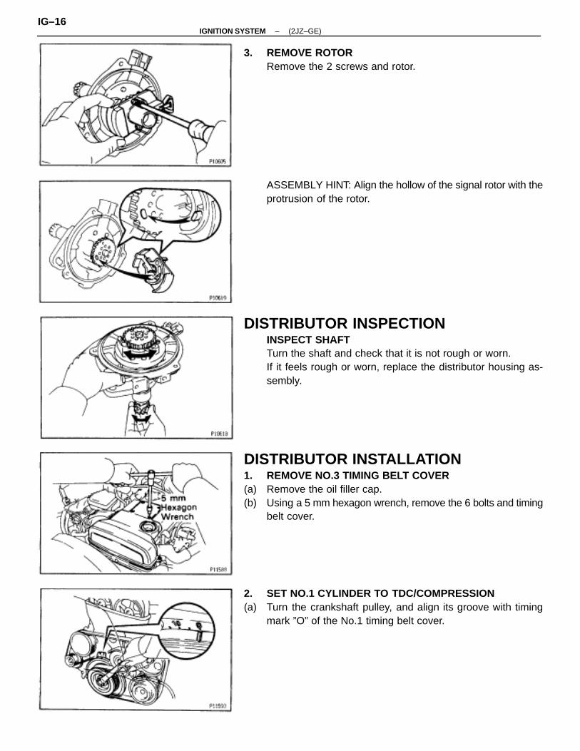
3. REMOVE ROTORRemove the 2 screws and rotor.
ASSEMBLY HINT: Align the hollow of the signal rotor with theprotrusion of the rotor.
DISTRIBUTOR INSPECTIONINSPECT SHAFTTurn the shaft and check that it is not rough or worn.If it feels rough or worn, replace the distributor housing as-sembly.
DISTRIBUTOR INSTALLATION1. REMOVE NO.3 TIMING BELT COVER(a) Remove the oil filler cap.(b) Using a 5 mm hexagon wrench, remove the 6 bolts and timing
belt cover.
2. SET NO.1 CYLINDER TO TDC/COMPRESSION(a) Turn the crankshaft pulley, and align its groove with timing
mark ”O” of the No.1 timing belt cover.
IG–16–IGNITION SYSTEM (2JZ–GE)
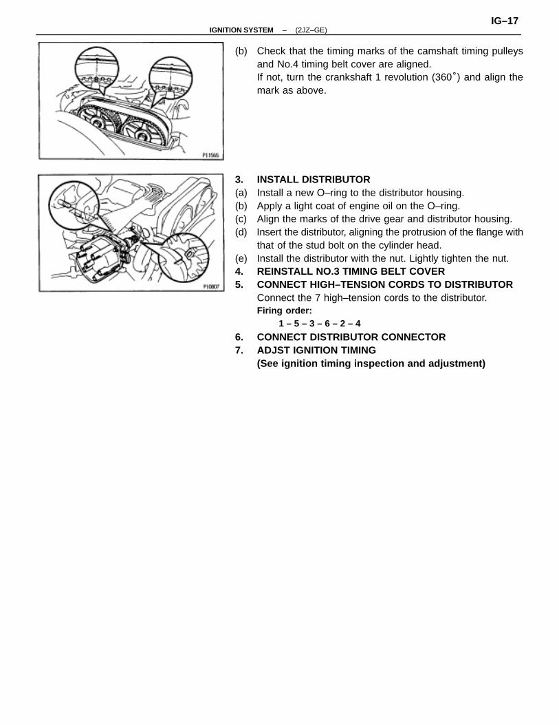
(b) Check that the timing marks of the camshaft timing pulleysand No.4 timing belt cover are aligned.If not, turn the crankshaft 1 revolution (360°) and align themark as above.
3. INSTALL DISTRIBUTOR(a) Install a new O–ring to the distributor housing.(b) Apply a light coat of engine oil on the O–ring.(c) Align the marks of the drive gear and distributor housing.(d) Insert the distributor, aligning the protrusion of the flange with
that of the stud bolt on the cylinder head.(e) Install the distributor with the nut. Lightly tighten the nut.4. REINSTALL NO.3 TIMING BELT COVER5. CONNECT HIGH–TENSION CORDS TO DISTRIBUTOR
Connect the 7 high–tension cords to the distributor.Firing order:
1 – 5 – 3 – 6 – 2 – 4
6. CONNECT DISTRIBUTOR CONNECTOR7. ADJST IGNITION TIMING
(See ignition timing inspection and adjustment)
–IGNITION SYSTEM (2JZ–GE)IG–17

SERVICE SPECIFICATIONSSERVICE DATAÑÑÑÑÑÑÑÑÑÑÑÑÑÑ
Firing orderÑÑÑÑÑÑÑÑÑÑÑÑÑÑÑÑÑÑÑÑÑÑÑÑÑÑÑÑÑÑ
–ÑÑÑÑÑÑÑÑÑÑÑÑÑÑÑÑÑÑÑÑÑÑÑÑÑÑÑÑÑÑÑÑ
1 – 5 – 3 – 6 – 2 – 4ÑÑÑÑÑÑÑÑÑÑÑÑÑÑÑÑÑÑÑÑÑ
High–tensioncord
ÑÑÑÑÑÑÑÑÑÑÑÑÑÑÑÑÑÑÑÑÑÑÑÑÑÑÑÑÑÑÑÑÑÑÑÑÑÑÑÑÑÑÑÑÑ
Resistance LimitÑÑÑÑÑÑÑÑÑÑÑÑÑÑÑÑÑÑÑÑÑÑÑÑÑÑÑÑÑÑÑÑÑÑÑÑÑÑÑÑÑÑÑÑÑÑÑÑ
25 k� per cord
ÑÑÑÑÑÑÑÑÑÑÑÑÑÑÑÑÑÑÑÑÑÑÑÑÑÑÑÑÑÑÑÑÑÑÑ
Spark plugÑÑÑÑÑÑÑÑÑÑÑÑÑÑÑÑÑÑÑÑÑÑÑÑÑÑÑÑÑÑÑÑÑÑÑÑÑÑÑÑÑÑÑÑÑÑÑÑÑÑÑÑÑÑÑÑÑÑÑÑÑÑÑÑÑÑÑÑÑÑÑÑÑÑÑ
Recommended spark plug NDNGK
Correct electrode gap for new plugMaximum electrode gap for used plug
ÑÑÑÑÑÑÑÑÑÑÑÑÑÑÑÑÑÑÑÑÑÑÑÑÑÑÑÑÑÑÑÑÑÑÑÑÑÑÑÑÑÑÑÑÑÑÑÑÑÑÑÑÑÑÑÑÑÑÑÑÑÑÑÑÑÑÑÑÑÑÑÑÑÑÑÑÑÑÑÑ
PK16R11BKR5EP111.1 mm (0.043 in.)1.3 mm (0.051 in.)
ÑÑÑÑÑÑÑÑÑÑÑÑÑÑÑÑÑÑÑÑÑÑÑÑÑÑÑÑÑÑÑÑÑÑÑ
Ignition coil ÑÑÑÑÑÑÑÑÑÑÑÑÑÑÑÑÑÑÑÑÑÑÑÑÑÑÑÑÑÑÑÑÑÑÑÑÑÑÑÑÑÑÑÑÑÑÑÑÑÑÑÑÑÑÑÑÑÑÑÑÑÑÑÑÑÑÑÑÑÑÑÑÑÑÑ
Primary coil resistance at cold at hotSecondary coil resistance at cold
at hot
ÑÑÑÑÑÑÑÑÑÑÑÑÑÑÑÑÑÑÑÑÑÑÑÑÑÑÑÑÑÑÑÑÑÑÑÑÑÑÑÑÑÑÑÑÑÑÑÑÑÑÑÑÑÑÑÑÑÑÑÑÑÑÑÑÑÑÑÑÑÑÑÑÑÑÑÑÑÑÑÑ
0.36–0.55 �0.45–0.65 �9.0–15.4 k�11.4–18.1 k�
ÑÑÑÑÑÑÑÑÑÑÑÑÑÑÑÑÑÑÑÑÑÑÑÑÑÑÑÑÑÑÑÑÑÑÑÑÑÑÑÑÑÑÑÑÑÑÑÑÑ
Distributor ÑÑÑÑÑÑÑÑÑÑÑÑÑÑÑÑÑÑÑÑÑÑÑÑÑÑÑÑÑÑÑÑÑÑÑÑÑÑÑÑÑÑÑÑÑÑÑÑÑÑÑÑÑÑÑÑÑÑÑÑÑÑÑÑÑÑÑÑÑÑÑÑÑÑÑÑÑÑÑÑÑÑÑÑÑÑÑÑÑÑÑÑÑÑÑÑÑÑÑÑÑÑÑÑÑ
Air gapPickup coil resistance at cold G1–G�
G2–G�
NE–G�
at hot G1–G�
G2–G�
NE–G�
ÑÑÑÑÑÑÑÑÑÑÑÑÑÑÑÑÑÑÑÑÑÑÑÑÑÑÑÑÑÑÑÑÑÑÑÑÑÑÑÑÑÑÑÑÑÑÑÑÑÑÑÑÑÑÑÑÑÑÑÑÑÑÑÑÑÑÑÑÑÑÑÑÑÑÑÑÑÑÑÑÑÑÑÑÑÑÑÑÑÑÑÑÑÑÑÑÑÑÑÑÑÑÑÑÑÑÑÑÑÑÑÑ
0.2–0.5 mm (0.008–0.020 in.)125–200 �125–200 �155–250 �160–235 �160–235 �190–290 �
TORQUE SPECIFICATIONSÑÑÑÑÑÑÑÑÑÑÑÑÑÑÑÑÑÑÑÑÑÑÑÑÑÑÑÑÑÑÑÑÑÑ
Part tightened ÑÑÑÑÑÑÑÑÑÑÑÑÑÑ
N⋅m ÑÑÑÑÑÑÑÑÑÑÑÑÑÑ
kgf⋅cm ÑÑÑÑÑÑÑÑÑÑÑÑÑÑ
ft⋅lbfÑÑÑÑÑÑÑÑÑÑÑÑÑÑÑÑÑÑÑÑÑÑÑÑÑÑÑÑÑÑÑÑÑÑ
Spark plug x Cylinder headÑÑÑÑÑÑÑÑÑÑÑÑÑÑ
18ÑÑÑÑÑÑÑÑÑÑÑÑÑÑ
180ÑÑÑÑÑÑÑÑÑÑÑÑÑÑ
13
IG–18–IGNITION SYSTEM 2JZ–GE