ifu esm+ - gentex
TRANSCRIPT
ESM+ Instructions for Use (pn: 414681 Revision 2) Dec 2017
1
ESM+ Powered Air Purifying Respirator (PAPR)
Models 50ESM+ and 60ESM+
INSTRUCTIONS FOR USE
USA / Canada
Rev 2, December 2017
Gentex Corporation
324 Main Street Simpson, PA 18407
USA Telephone : (570)282-3550
Fax : (570) 282-8555 Toll Free : 800 251 7377
Email : [email protected] http://www.gentexcorp.com
11
TABLE OF CONTENTS
1. FOR YOUR SAFETY 5
1.1 GENERAL SAFETY STATEMENTS 5
1.2 DEFINITIONS OF ALERT ICONS 5
2. DESCRIPTION 6
2.1 SYSTEM OVERVIEW 6
2.2 COMPONENTS ERROR! BOOKMARK NOT DEFINED.
2.2.1 POWERED AIR PURIFYING RESPIRATOR (PAPR) 7
2.2.2 FILTER(S) AND CARTRIDGE(S) 7
2.2.3 RECHARGEABLE BATTERY PACK 7
2.2.4 BATTERY CHARGER 7
2.2.5 VISOR LOCK 7
2.2.6 STORAGE BAG 7
2.2.7 INSTRUCTIONS FOR USE USA/CANADA 7
2.2.8 PRODUCT LIMITED WARRANTY 7
2.3 FUNCTIONAL DESCRIPTION 8
42.4 INTENDED USE 9
2.5 LIMITATIONS ON USE 9
2.6 RESPIRATORY PROGRAM MANAGEMENT 10
2.7 APPROVALS 10
12
3.0 USE 11
3.1 PRECONDITIONS FOR USE 11
3.2 PREPARATIONS FOR USE 11
3.2.1 PERFORM A VISUAL INSPECTION 11
3.2.2 BATTERY CHARGING AND ISTALLATION 11
3.2.3 HEADBAND POSITION 13
3.2.4 FILTER OR CARTRIDGE INSTALLATION 14
3.2.5 FILTER OR CARTRIDGE REMOVAL 15
3.3 DONNING THE DEVICE 16
3.4 SWITCHING ON THE DEVICE 18
3.5 USE WHEN THE FACESHIELD IS RAISED 20
3.6 DURING USE 21
3.6.1 WARNINGS 22
3.7 AFTER USE 22
4.0 TROUBLESHOOTING 23
4.1 WARNINGS 23
5. MAINTENANCE 24
5.1 MAINTENANCE INTERVALS 24
5.2 CLEANING AND DISINFECTING 24
5.2.1 CLEANING AND DISINFECTING THE DEVICE 25
5.3 MAINTENANCE WORK 25
13
5.3.1 VISUAL INSPECTION 34
5.3.2 CHECKING THE BATTERY PACK CAPACITY 34
5.3.3 REPLACING OR CHARGING THE BATTERY PACK 35
5.3.4 REPLACING THE FILTER OR CARTRIDGE 36
6. TRANSPORT 37
7. STORAGE 37
8. DISPOSAL 38
9. TECHNICAL DATA 39
10. RESPIRATORY APPROVAL LABEL 42
11. FILTER APPROVAL LABEL 43
12. COMPLETE UNITS 44
13. PUREFLO ESM+ ACCESSORIES 45
14. PUREFLO ESM+ SPARES/REPLACEMENT PARTS 46
14
1. For Your Safety
1.1 General safety statements
• Before using this product, carefully read and understand these Instructions for Use and those of
associated components.
• Strictly follow the Instructions for Use. The user must fully understand and strictly observe the
instructions. Use the product only for the purposes specified in the intended use section of this
document.
• Do not dispose of the Instructions for Use. Ensure that they are retained and appropriately used by
the product user.
• Only trained and competent users are permitted to use this product.
• Follow the local and national guidelines pertaining to this product.
• Only trained and competent personnel are permitted to inspect, repair and service the product.
• Use only genuine Pureflo spare parts and accessories, or the proper functioning of the product may
be impaired.
• Do not use a faulty or incomplete product. Do not modify the product.
• Materials that may come into contact with the wearer’s skin could cause allergic reactions to
susceptible individuals.
• Notify Gentex in the event of any product or component fault or failure.
1.2 Definitions of alert icons
The following warning symbols are used in this document to provide and highlight areas of the
associated text that require a greater level of awareness from the user. The meanings of the symbols
are as follows:
WARNING
Indicates a potentially hazardous situation which, if not avoided, could result in
death or serious injury.
CAUTION
Indicates a potentially hazardous situation which, if not avoided, could not
result in physical injury, or damage to the product or environment. It may also be used
to warn against unsafe practices.
15
NOTICE
Indicates additional information on how to use the product.
2. Description
2.1 System Overview
The Pureflo Models PF50ESM+ (bump cap and the P-Series or Pharmaceutical variant) and
PF60ESM+ (hardhat model) are self-contained powered air purifying respirator (PAPR).
2.2 Components
2.2.1 Powered Air Purifying Respirator unit (PAPR)
The Pureflo incorporates an Electronic Systems Management (ESM) which monitors both the filter
state and battery power assuring continuous airflow above 170 lpm for the entire period of use. Should
airflow or power drop, these units will alert the user.
2.2.2 Filter(s) and Cartridge(s)
The Pureflo Models PF50ESM+ and PF60ESM+ should only be used with original Pureflo ESM filters. When equipped with a High Efficiency Particulate Air (HEPA) HE filter (order number PR02020SP), they are effective against solid and liquid aerosols (particulates). When equipped with an HE/HF/HC cartridge (order number PR02026SP), these respirators are effective against Hydrogen Chloride (HC) and Hydrogen Fluoride in addition to particulates. This cartridge is also effective for nuisance level removal of most organic vapors, inorganic vapors, acid gases and ozone, where ‘nuisance level’ refers to concentrations not exceeding the OSHA PEL or other applicable government occupational exposure limits, whichever is lower. NIOSH does not approve filters for Nuisance level protection.
The use of any other filter(s) is prohibited.
2.2.3 Rechargeable Battery Pack
The Pureflo ESM+ is powered by rechargeable battery packs held inside the respirator
2.2.4 Battery Charger
The Pureflo ESM+ comes with two (2) battery chargers (part number PR02230).

16
2.2.5 Visor Lock – Installation/Removal (except 50ESM+ P-Series)
Visor Lock insertion channel
Visor Lock –
side view Visor Lock -
Topside, Tail End
Tail
Visor Lock -
Underside
Over
Visor
Locking
Channel
Visor Lock Installation 1. Refer to the pictures above and identify the top side, the Over-Visor locking channel, and the tail end of
the visor clip. 2. Ensure the visor is completely in the down position during the following steps. 3. Refer to drawing of figure above; locate the center of the rubber gasket attached to the primary
visor and using your fingers, pull outward and downward and hold. Identify the visor lock insertion channel in the main chassis.
4. Ensure the visor locking channel is facing down toward the top of the visor and fully insert the tail end of the visor clip into the slot of the unit’s frame.
5. With your fingers, simultaneously push the top of the visor downward and lift the locking clip upwards. Pull outward on the visor to locate the visor into the visor locking channel of the clip. Release the rubber gasket.
Visor Lock Removal
1. Repeat step 3 from above. 2. Using your fingers, push downward on the top of the visor and lift the locking clip upward. The visor
should release from the locking channel but may require inward pressure on the top of the visor while lifting the locking clip upward.
3. Slide the locking clip out from the slot of the main frame. 4. Release the rubber gasket.
17
2.2.6 Storage Bag
The Pureflo ESM+ comes with one (1) Storage Bag (part number 838003).
2.2.7 Instructions for use USA/Canada
The Pureflo ESM+ comes with one (1) Instructions for Use- this document.
2.2.8 Product Limited Warranty
The Pureflo ESM+ comes with one (1) Product Limited Warranty card (part number QC057).
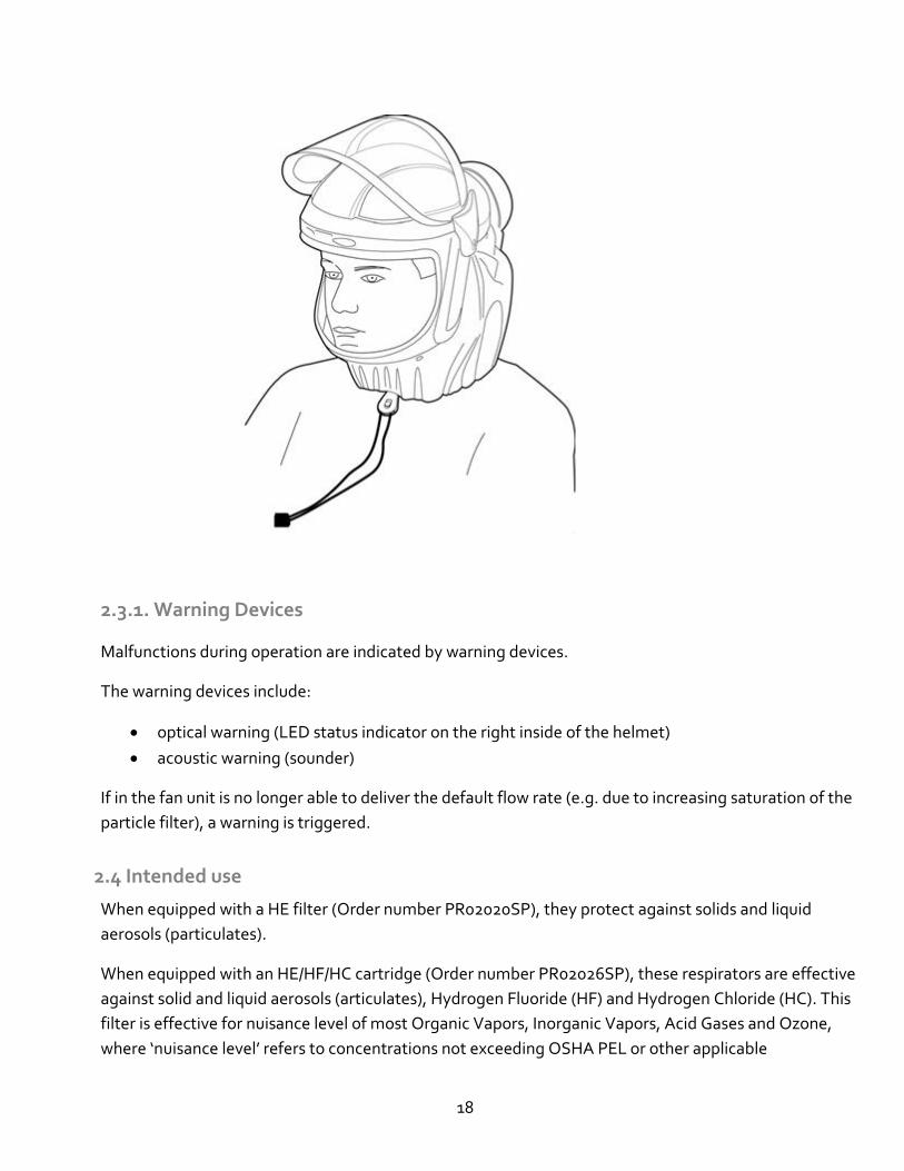
2.3 Functional Description
The powered air purifying respirator is a respiratory protective device depending on circulating air.
It filters the ambient air and makes it available as breathable air. The device continuously takes in
ambient air through the filter. The filter absorbs harmful particulates. In this way, the ambient air is
recycled and finally reaches the face/breathing zone. There it is available as breathable air.
An adjustable neck cape ensures that continuous positive pressure is maintained within the respirator,
preventing ambient air from penetrating.
The Pureflo ESM+ provides head, face and eye protection. (Depending on the installed accessory components)
The Pureflo ESM+ is powered by rechargeable battery packs held inside the respirator.
The Pureflo ESM+ contains an adjustable headband and crown strap ensuring a comfortable fit for most head sizes from sizes.
18
2.3.1. Warning Devices
Malfunctions during operation are indicated by warning devices.
The warning devices include:
• optical warning (LED status indicator on the right inside of the helmet)
• acoustic warning (sounder)
If in the fan unit is no longer able to deliver the default flow rate (e.g. due to increasing saturation of the
particle filter), a warning is triggered.
2.4 Intended use
When equipped with a HE filter (Order number PR02020SP), they protect against solids and liquid
aerosols (particulates).
When equipped with an HE/HF/HC cartridge (Order number PR02026SP), these respirators are effective
against solid and liquid aerosols (articulates), Hydrogen Fluoride (HF) and Hydrogen Chloride (HC). This
filter is effective for nuisance level of most Organic Vapors, Inorganic Vapors, Acid Gases and Ozone,
where ‘nuisance level’ refers to concentrations not exceeding OSHA PEL or other applicable
19
government occupational exposure limits, whichever is lower. NIOSH does not approve filters for
Nuisance level protection.
Note that the Pureflo ESM+ does not monitor remaining service life for HF, HC, or other vapors or
gases. Users must determine an appropriate cartridge change out schedule.
2.5 Limitations on use
The device is not suitable for use:
• in atmospheres that are oxygen deficient;
• where contaminant concentrations are unknown;
• where contaminant concentrations are Immediately Dangerous to Life or Health (IDLH);
• where contaminant concentrations exceed the maximum use concentration (MUC) determined
by using the Assigned Protection Factor (APF) for the specific respirator system or the APF
mandated by specific government standards, whichever is lower;
• in unventilated areas;
• outside the intended temperature range of 40°F to 105°F (+5°C to +40°C);
WARNING
Immediately exit the contaminated area if any of the low battery or low airflow alarms activate.
The recommended altitude range of the PureFlo ESM+ is approximately sea level to 2600 feet (800
meters).
2.6 Respiratory Program Management
Occupational use of respirators must be in compliance with applicable health and safety standards. By
United States regulation employers must establish a written respirator protection program meeting the
requirements of the Occupational Safety and Health Administration (OSHA) Respiratory Protection
standard 29 CFR 1910.134 and any applicable OSHA substance specific standards. For additional
information on this standard contact OSHA at www.OSHA.gov. In Canada, CSA standard Z94.4
requirements must be met and/or requirements of the applicable jurisdiction as appropriate.
20
2.7 Approvals
The device is approved according to:
• Respiratory Protection: NIOSH 42CFR84, CSA standard Z94.4
• Head Protection (PF60ESM+ only): ANSI / ISEA Z89.1:2014 Type I Class G High Visibility colored tops comply with the High Visibility requirements of ANSI/ISEA ZZ89.1-2014
• Eye Protection: ANSI / ISEA Z87.1:2015 Impact Rated ( Z87+)
• Hearing Protection ANSI / US EPA Regulation 40 CFR Part 211,
Subpart B
• FM Approval to US and CSA standards for: NI / Class I, II, III, Div 2, Groups A, B,C,D,E,F,G
T4, Ta=40 C
Explanation of type-identifying marking and symbols
Product Approval Label reference to be inserted
21
3. Use
3.1 Preconditions for use
The ambient conditions (in particular type and concentration of contaminants) must be known.
The oxygen content of the ambient air must not drop below the following limit values:
At least 19.5% oxygen in the USA
Observe the national guidelines in other countries.
3.2 Preparations for use
The following tasks must be performed prior to use. Perform the following activities outside the danger
zone:
3.2.1. Perform a visual inspection
• Visually inspect the entire helmet/PAPR system. If parts are missing or damaged replace them
before proceeding.
• Confirm that the battery packs are fully charged and charge is sufficient for duration of the work
period.
• Visually inspect the neck cape material for damage
• Check the operation of the neck cape toggle fastener.
• Check the neck cape attachment to the respirator chassis
• Check the exhale patch for contamination
• Check the visor seal for damage
• For respirators with lift type visors; check the two (2) visor pivot screws to ensure tightness
• PF50ESM+ Pharmaceutical, check the two (2) visor securing screws and nuts, tighten or replace
as appropriate
• Visually inspect the helmet shell for damage
Replace any damaged parts including scratched or damaged visors (Refer to ordering list at the end
of this manual)
22
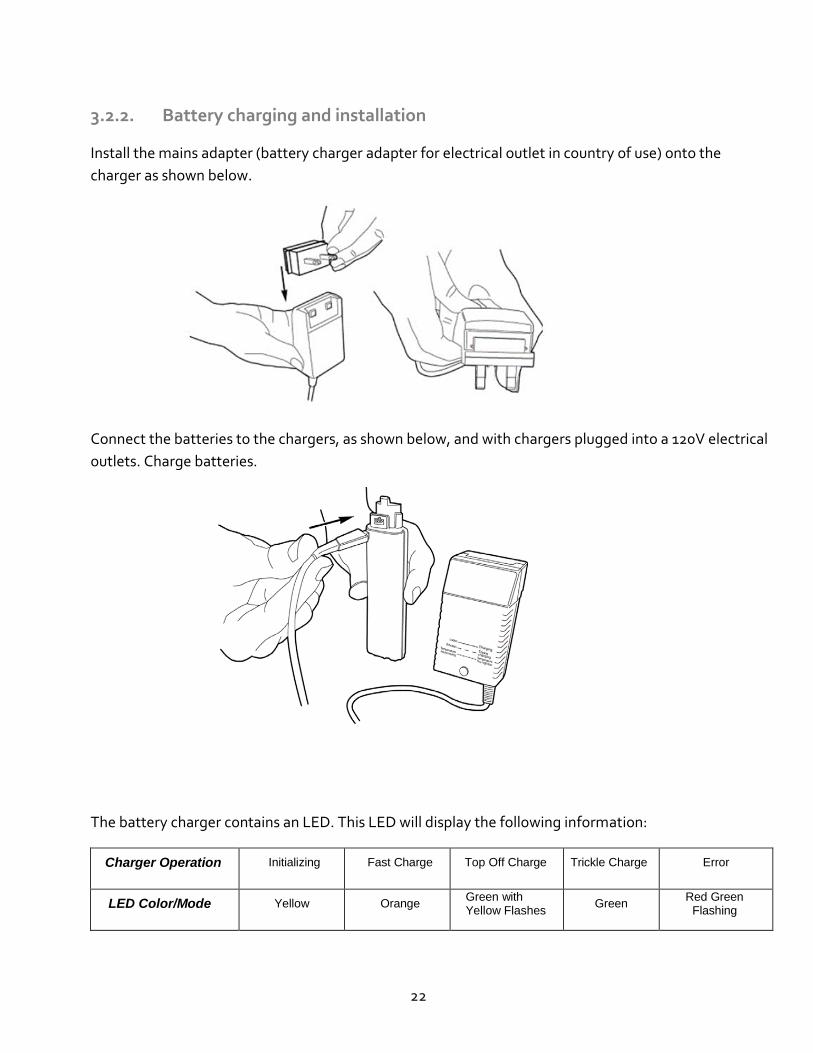
3.2.2. Battery charging and installation
Install the mains adapter (battery charger adapter for electrical outlet in country of use) onto the
charger as shown below.
Connect the batteries to the chargers, as shown below, and with chargers plugged into a 120V electrical
outlets. Charge batteries.
The battery charger contains an LED. This LED will display the following information:
Charger Operation Initializing Fast Charge Top Off Charge Trickle Charge Error
LED Color/Mode Yellow Orange Green with Yellow Flashes
Green Red Green
Flashing
23
Inspect battery pack initially and prior to each charge cycle. If cracks or damage to the case is noted do
not charge the battery pack. Properly dispose of battery pack and replace.
Place chargers in a cool, well ventilated location free of particulates or other airborne contamination.
Charge in an area free of combustible material and readily monitored. Plug charger into a 120 volt,
50/60Hz wall outlet or power source.
NOTICE
Always disconnect the charger from power supply if not in use.
The nominal recharge time for a battery pack is 2.5 hours. Completely discharged batteries may require
more time. If the LED flashes red/green, unplug the charger and contact your distributor.
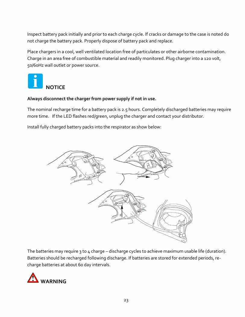
Install fully charged battery packs into the respirator as show below:
The batteries may require 3 to 4 charge – discharge cycles to achieve maximum usable life (duration).
Batteries should be recharged following discharge. If batteries are stored for extended periods, re-
charge batteries at about 60 day intervals.
WARNING
24
DO NOT place charger near storage areas for volatile solvents such as: Carbon Tetrachloride,
Gasoline, Benzene, Paint Thinner, or household spray cleaners may crack the battery case.
DO NOT place your charger in a room colder than 50°F (+10° C) or warmer than 100°F (+38° C).
Temperature extremes may alter batteries charging characteristics.
DO NOT place charger near sources of sparks or other possible causes of ignition. Batteries on
charge may emit EXPLOSIVE hydrogen gas!
WARNING
• Failure to follow safety precautions and warnings can result in fire, serious injury, or death.
• Using a damaged battery pack could cause a fire, serious injury or death
• Always make sure you have read, understood, and follow the instructions on how to use and
to care for your battery pack.
25
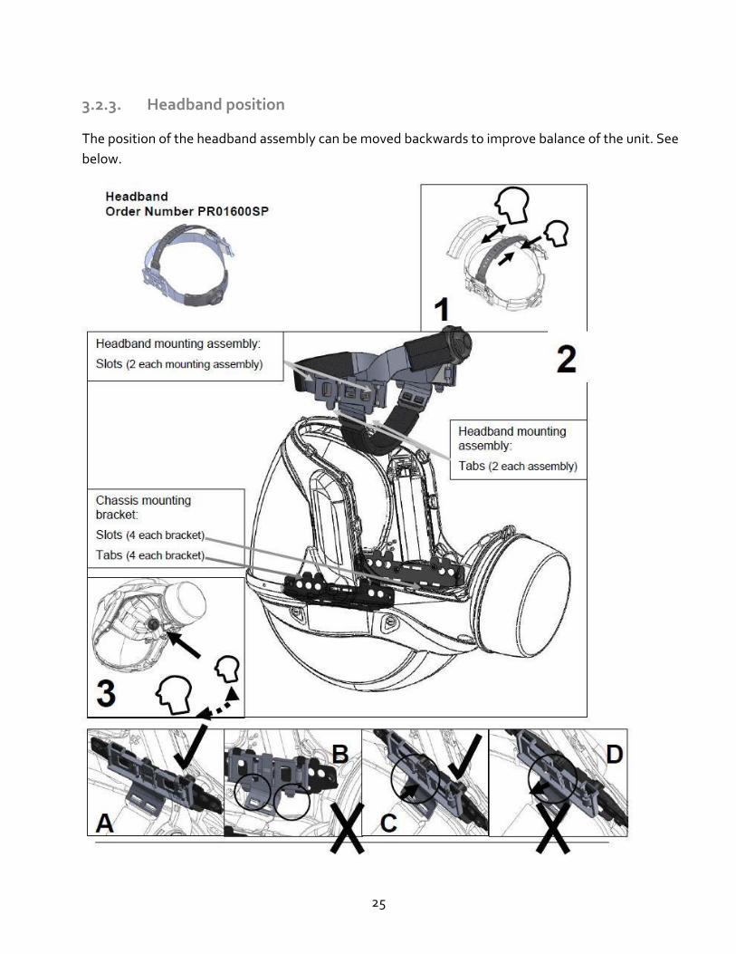
3.2.3. Headband position
The position of the headband assembly can be moved backwards to improve balance of the unit. See
below.
26
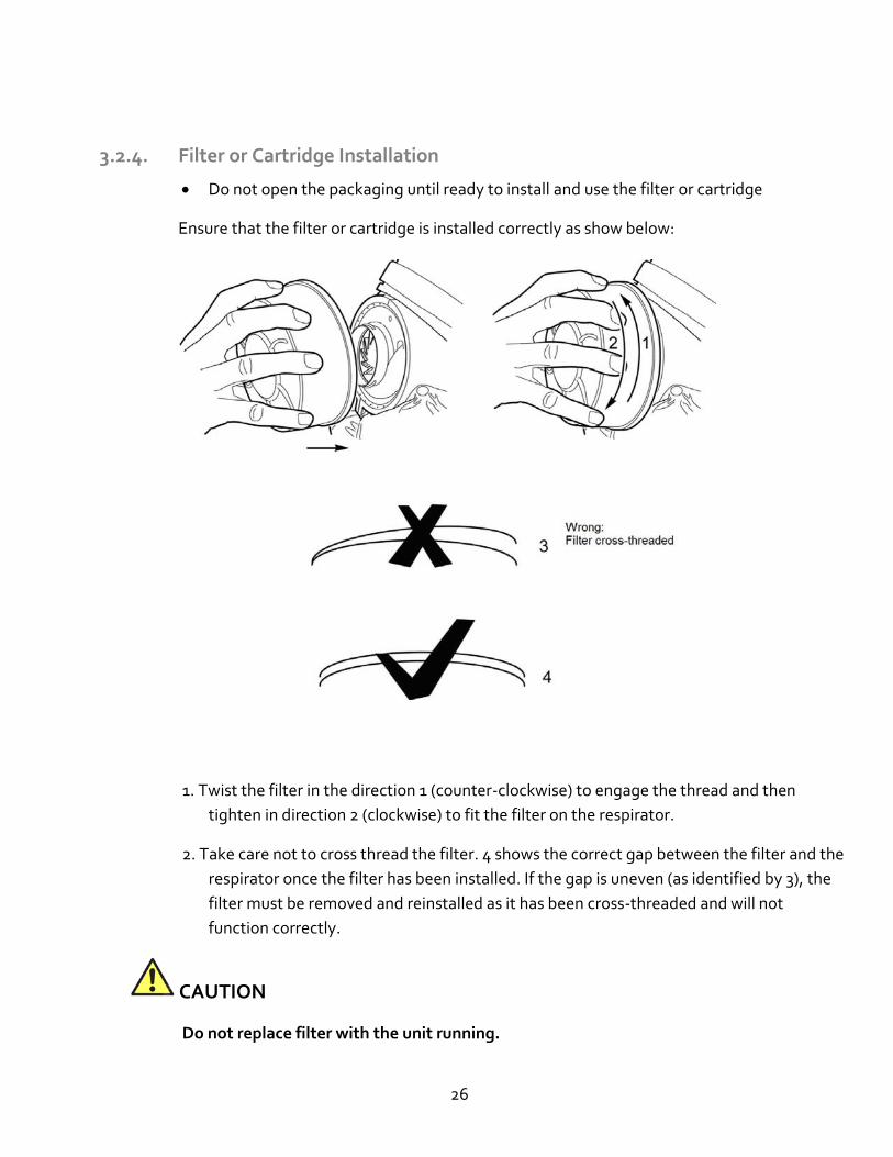
3.2.4. Filter or Cartridge Installation
• Do not open the packaging until ready to install and use the filter or cartridge
Ensure that the filter or cartridge is installed correctly as show below:
1. Twist the filter in the direction 1 (counter-clockwise) to engage the thread and then
tighten in direction 2 (clockwise) to fit the filter on the respirator.
2. Take care not to cross thread the filter. 4 shows the correct gap between the filter and the
respirator once the filter has been installed. If the gap is uneven (as identified by 3), the
filter must be removed and reinstalled as it has been cross-threaded and will not
function correctly.
CAUTION
Do not replace filter with the unit running.
27
3.2.5. Filter or Cartridge Removal
Ensure that the unit is off. Do not replace filter with the unit running. Repeat procedure from
previous section in reverse order
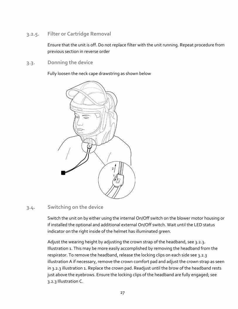
3.3. Donning the device
Fully loosen the neck cape drawstring as shown below
3.4. Switching on the device
Switch the unit on by either using the internal On/Off switch on the blower motor housing or
if installed the optional and additional external On/Off switch. Wait until the LED status
indicator on the right inside of the helmet has illuminated green.
Adjust the wearing height by adjusting the crown strap of the headband, see 3.2.3.
Illustration 1. This may be more easily accomplished by removing the headband from the
respirator. To remove the headband, release the locking clips on each side see 3.2.3
illustration A if necessary, remove the crown comfort pad and adjust the crown strap as seen
in 3.2.3 illustration 1. Replace the crown pad. Readjust until the brow of the headband rests
just above the eyebrows. Ensure the locking clips of the headband are fully engaged; see
3.2.3 Illustration C.
28
The respirator headband must be adjusted to achieve a snug, comfortable, and balanced fit
prior to entering the work environment. Increase the headband circumference by pressing
the center button and turning the ratchet adjustment knob counter-clockwise as shown in
number. Reduce the headband circumference by rotating the ratchet knob clockwise. Take
care to not kink or distort the head strap while adjusting the headband circumference.
Improving the forward/backward balance of the respirator is accomplished by locating the
headband on either the front or rear set of tabs of the mounting bracket attached to the
respirator frame. Refer to 3.2.3 Illustration 2+3.
The respirator can be used in conjunction with corrective prescription spectacles and
compatible hearing protection. (Ear plugs or custom molded ear plugs)
CAUTION
Corrective prescription eye protection may transmit impacts from high-speed particles, thus
creating a hazard to the wearer.
Do not hold or suspend the respirator by the neck cape or headband.
Adjust the neck cape using the toggle fastener to tighten the drawstring and provide a
comfortable seal against the neck. See section 3.3.
Firmly close the visor and check that the neck cape inflates slightly, indicating positive
pressure within the helmet. If the neck cape does not inflate, perform step 7 again and also
check that the neck cape is correctly attached to the respirator chassis. See section 5.3 neck
cape replacement.
The neck capes are secured by fasteners (snaps). The boss side of the snap fastener attached
to the respirator frame are replaceable (refer to the Parts Order List at the end of this
document). The snaps installed on the neck cape are not replaceable, if they are damaged a
replacement neck cape. If new neck cape fasteners are required on the helmet, remove the
old self-tapping screws and cape, screw bosses, and install new parts.
WARNING Penetration of ambient air! Make sure that the neck cape is securely and firmly in place before each use.
29
3.5 . Use when the face shield is raised:
WARNING
With the face shield in the up position no respiratory protection is to be expected.
3.6. During use
WARNING
Health hazard!
Leave the danger zone (but continue to wear PAPR) immediately in case of:
• Decreasing or interrupted air supply (e.g. fan failure) in the helmet, carbon dioxide can
quickly build up or lack of oxygen may occur. Noxious ambient air may also penetrate the
helmet.
• Drowsiness, dizziness, or other complaints
• Breathing becomes difficult
• Damage to the equipment
• An audible warming sounds
• An optical red warning signal appears on the left side status indicator LED
• Other indicated warnings
At very high work rates and peak inhalation the pressure flow in the helmet may become negative.
Unfiltered ambient air could penetrate the system!
WARNING
In the power-off state no respiratory protection is to be expected, and this is considered to be
an abnormal situation.
30
WARNING
In the power-off state there will be a rapid build-up of carbon dioxide and depletion of oxygen
may occur if the face shield is kept down with the neck cape still in place.
3.6.1. Warnings
Explanation of the status LED
Indicator Acoustic warning (sounder) Explanation
Status LED is red until normal operating point is reached
No tone Switching On
Status LED is green
Illuminated steady
No tone Normal Operation
Status LED is red
Flashing fast
Fast three (3) tones Low Airflow
Status LED is red
Flashing slow
Slow two (2) tone Low Battery
Status LED is red
Flashing fast
Fast three (3) tones Filter not fitted
3.7. After use
Do the following:
1. Leave the hazardous area. Do not remove or shut off the PAPR until you have vacated the hazardous area.
2. Fully loosen the neck cape drawstring by releasing the toggle fastener.
3. Fully loosen the headband ratchet knob as this may aid removal
4. Doff the respirator/ PAPR helmet and turn it off.
5. Place the respirator in a suitable container if special decontamination procedures are required.
31
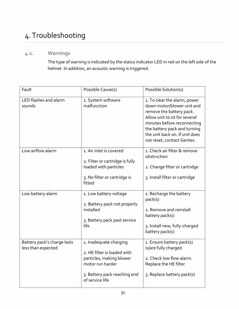
4. Troubleshooting
4.1. Warnings
The type of warning is indicated by the status indicator LED in red on the left side of the
helmet. In addition, an acoustic warning is triggered.
Fault Possible Cause(s) Possible Solution(s)
LED flashes and alarm sounds
1. System software malfunction
1. To clear the alarm, power down motor/blower unit and remove the battery pack. Allow unit to sit for several minutes before reconnecting the battery pack and turning the unit back on. If unit does not reset, contact Gentex.
Low airflow alarm 1. Air inlet is covered
2. Filter or cartridge is fully loaded with particles
3. No filter or cartridge is fitted
1. Check air filter & remove obstruction
2. Change filter or cartridge
3. Install filter or cartridge
Low battery alarm
1. Low battery voltage
2. Battery pack not properly installed
3. Battery pack past service life
1. Recharge the battery pack(s)
2. Remove and reinstall battery pack(s)
3. Install new, fully-charged battery pack(s)
Battery pack’s charge lasts less than expected
1. Inadequate charging
2. HE filter is loaded with particles, making blower motor run harder
3. Battery pack reaching end of service life
1. Ensure battery pack(s) is/are fully charged
2. Check low flow alarm. Replace the HE filter
3. Replace battery pack(s)
32
5. Maintenance
5.1 Maintenance intervals
Work to do
Bef
ore
use
Aft
er u
se
Eve
ry 6
mo
nth
s
Eve
ry 3
yea
rs
Eve
ry 5
yea
rs
Eve
ry 1
0 y
ears
As
ne
cess
ary
Clean and disinfect the device X
Visual Inspection X
test battery pack capacity X X
Replace rechargeable battery pack (s) X X*
Charge rechargeable battery pack (s) X
Replace filter cartridge X
Check flow rate and warning devices X
Replace face shield X
Replace helmet shell X
* Rechargeable cycles >500 cycles
5.2 Cleaning and disinfecting
CAUTION
Potential damage to components!
Only use the prescribed processes and the cleaning and disinfection agents specified for
cleaning and disinfecting. Other agents, methods, dosages and contact times may
damage the components.
33
Health hazard!
The undiluted agents are damaging to health if they come into direct contact with the
eyes or skin. Wear safety goggles and protective gloves when working with these
agents.
5.2.1 Cleaning and disinfecting the device
• Clean all parts with lukewarm water and a mild solution of a household liquid soap.
PUREWIPE (Part No.: PR02054SP) cleaning wipes can also be used for this purpose.
• Do not immerse the PAPR in water or any other fluid.
• Do not use organic solvents or abrasive cleaning agents on any part of the PAPR
• Launder the neck cape contact Gentex or visit our website for proper laundering
instructions for the white pinstriped integrity neck capes) and 3 head lining pads of the
headband as required using a mild solution of a household detergent and water.
• For units with gross contamination ensure visor is down and unit is upright when
cleaning. For ingrained dirt on the outside of the unit (excluding visor), a nailbrush,
ultrasonic brush or scouring pad may be used. Dry the unit with a clean lint free cloth -
do not use heat source.
• Clean concussion strap, crown net and comfort pads using a mild solution of household
detergent and water (Max 90°F (+30°C)), air dry only
• Headbands can be removed from the helmet for washing and are considered dishwasher
safe.
Disposal of parts should be as described in the disposal section of these Instructions for Use
or in accordance with the authority having jurisdiction.
• If a PAPR has been used in an area that has caused it to become contaminated with a
substance requiring special decontamination procedures, observe the precautions
described in the manufacturer's material safety data sheet for that substance.
5.3 Maintenance work
The respirator is designed with many owner replaceable parts. If it should require return to the
manufacturer, please note that you (customer) will be asked to provide the unit serial number. This
is located on the inside of the frame, in the battery compartment, on the left side of the helmet (in
the worn position). A Respirator Return Procedure form (at the end of this document or available
from our website must be completed by you, the customer.
34
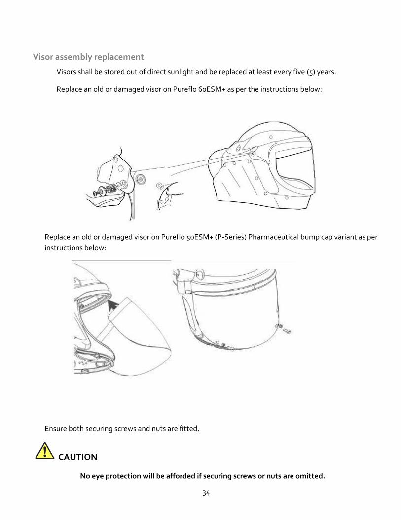
Visor assembly replacement
Visors shall be stored out of direct sunlight and be replaced at least every five (5) years.
Replace an old or damaged visor on Pureflo 60ESM+ as per the instructions below:
Replace an old or damaged visor on Pureflo 50ESM+ (P-Series) Pharmaceutical bump cap variant as per
instructions below:
Ensure both securing screws and nuts are fitted.
CAUTION
No eye protection will be afforded if securing screws or nuts are omitted.
35
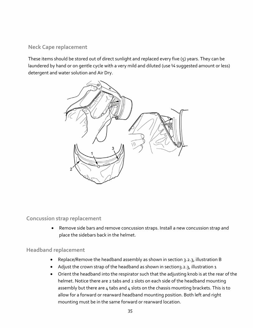
Neck Cape replacement
These items should be stored out of direct sunlight and replaced every five (5) years. They can be
laundered by hand or on gentle cycle with a very mild and diluted (use ¼ suggested amount or less)
detergent and water solution and Air Dry.
Concussion strap replacement
• Remove side bars and remove concussion straps. Install a new concussion strap and
place the sidebars back in the helmet.
Headband replacement
• Replace/Remove the headband assembly as shown in section 3.2.3, illustration B
• Adjust the crown strap of the headband as shown in section3.2.3, illustration 1
• Orient the headband into the respirator such that the adjusting knob is at the rear of the
helmet. Notice there are 2 tabs and 2 slots on each side of the headband mounting
assembly but there are 4 tabs and 4 slots on the chassis mounting brackets. This is to
allow for a forward or rearward headband mounting position. Both left and right
mounting must be in the same forward or rearward location.
36
• Mounting is correct when the rounded tabs of the headband are inserted into the
rectangular slots of the chassis-mounting bracket and the rounded tabs of the chassis-
mounting bracket are inserted into the rectangular slots of the headband. Section,
illustration A shows correct tab and slot engagement. Section, Illustration B show
incorrect tab and slot engagement because the tabs are not inserted into the slots of the
chassis mounting bracket.
• Following rounded ta and rectangular slot engagement, ensure the locking clip (square
tab) of the headband is engaged as shown in Section, illustration C. Section, illustration
D shows the locking clip not fully engaged and therefore the headband is not secured.
• This design allows easy removal of the headband for adjustment and cleaning. To
remove the headband, first release the locking clip and lift the headband out of the
helmet.
• When reinstalling, select the forward or backward headband position which provides the
best stability while wearing the respirator. Stability may be affected by the head size of
the user, alternate filters, and accessories.
• Adjust the headband to achieve a snug fit by the adjustment knob Section, illustration 3.
• Replace headbands at least every five (5) years or if deterioration or damage is observed.
WARNING
The headband, concussion strap, fixings and mounting points form part of the integral protection
system of the helmet. Do not modify the product. Ensure that the new headband is fitted correctly
or the head protection may be compromised.
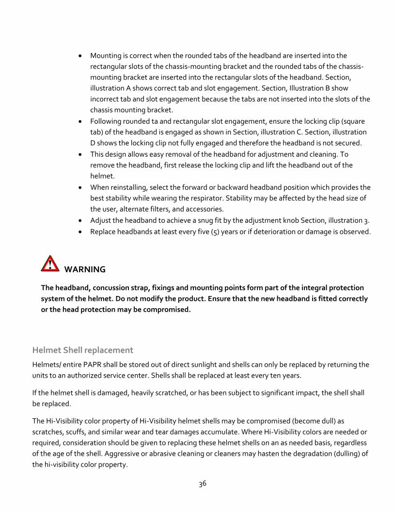
Helmet Shell replacement
Helmets/ entire PAPR shall be stored out of direct sunlight and shells can only be replaced by returning the
units to an authorized service center. Shells shall be replaced at least every ten years.
If the helmet shell is damaged, heavily scratched, or has been subject to significant impact, the shell shall
be replaced.
The Hi-Visibility color property of Hi-Visibility helmet shells may be compromised (become dull) as
scratches, scuffs, and similar wear and tear damages accumulate. Where Hi-Visibility colors are needed or
required, consideration should be given to replacing these helmet shells on an as needed basis, regardless
of the age of the shell. Aggressive or abrasive cleaning or cleaners may hasten the degradation (dulling) of
the hi-visibility color property.
37
Blower / motor / fan assembly replacement
Replace the blower / motor / fan assembly as shown below:
Note that the blower / motor / fan assembly is designed to fit tightly into the chassis. A weak solution of a
household liquid soap and water may be used as a lubricant on the outer rubber sleeve during installation.
After installing a new blower / motor / fan assembly, perform the following checks:
•
NOTICE
Replacement or servicing beyond the tasks described above requires sending the device(s) back to a
Gentex authorized repair facility.
5.3.1. Visual inspection
Check all parts thoroughly and replace damaged parts if necessary.
5.3.2. Checking the battery pack capacity
5.3.3. Replacing or charging the battery pack
See 3.2.2
5.3.4. Replacing the filter
• All filters and cartridges must be replaced when the LED indicator is illuminated red.
The red LED and audible alarm indicates that the HE (HEPA) filter material is plugged
or blocked to the degree where Pureflo ESM+ can no longer provide sufficient airflow
to the respirator user.
• Install the new filter as show in Section on page. Twist the filter counterclockwise to
engage the thread and then tighten clockwise to fit the filter onto the respirator.
• The Pureflo ESM+ has no end of service life detection (gases and vapors)
• Replace cartridges for protection against vapor/gases according to your employers
change out schedule or sooner if contaminant is detected within the breathing zone
of the respirator.
• Never attempt to clean the HE filter cartridge by knocking or blowing out
accumulated material. Doing so will damage the filter media.
38
• Store the filter as described in these Instructions for Use within the recommended
storage temperature conditions and observe filter expiration dates.
WARNING
No Protection without a filter cartridge!
Do not use the device without a filter cartridge.
CAUTION
Damage to fan unit due to penetration of particles!
Make sure when you remove the filter cartridge that no particles enter the device
through the suction inlet.
NOTICE
For further advice and support on fitting and cleaning procedures contact Gentex.
Only perform maintenance tasks described in these Instructions for Use.
6. Transport
Transport the device(s) in the original packaging or in the optionally available Pureflo PAPR bag (Order number PR ) to protect it from physical damage.
7. Storage
The device(s) should be stored in dry, clean conditions away from direct sunlight and thermal radiation.
Store the unit(s) within the temperature range of 40°F to 105°F (+5°C to 40°C)
39
Maximum storage area humidity (≤ 90% relative humidity) Storing rechargeable batteries: Do not store rechargeable batteries for prolonged periods outside the recommended temperature range. This might reduce the remaining capacity and number of charges.
8. Disposal
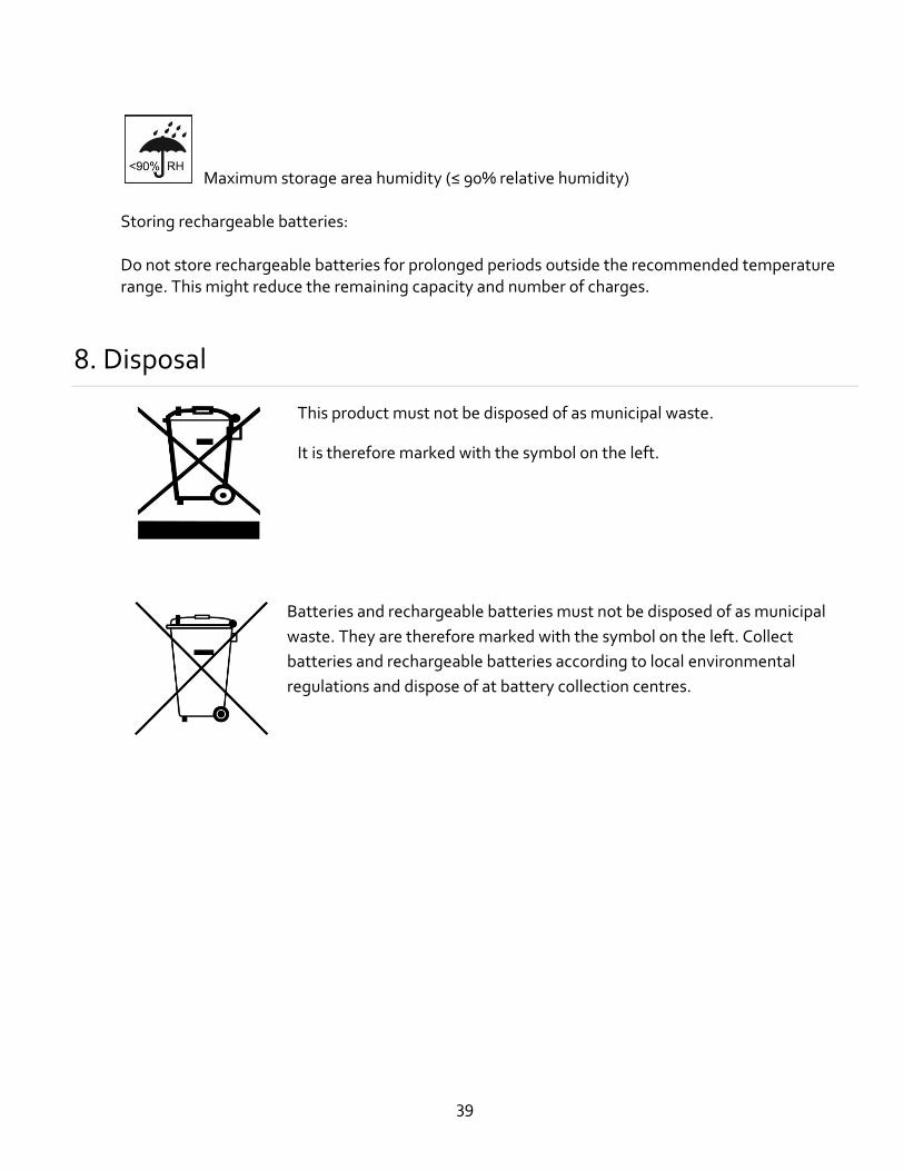
This product must not be disposed of as municipal waste.
It is therefore marked with the symbol on the left.
Batteries and rechargeable batteries must not be disposed of as municipal
waste. They are therefore marked with the symbol on the left. Collect
batteries and rechargeable batteries according to local environmental
regulations and dispose of at battery collection centres.
40
9. Technical data
Overall System
Air Flow Rate 210 L/min (170 L/min minimum) : 7 CFM (6CFM Minimum)
Rated Period of Service 6 hrs.
Respiratory System Operating
Temperature
40°F to 105°F (+5°C to 40°C)
Operating / Storage Area
Humidity
≤ 90 % relative humidity
Storage Temperature 40°F to 105°F (+5°C to 40°C)
Operating Altitude Range 0-2600’
System Classification Powered Air Purifying Respirator
Respiratory Protection NIOSH 42 CFR part 84
CSA standard Z94.4
OSHA Assigned Protection
Factor
APF1000** with neck cape (per OSHA assigned protection factor,
federal register notice 71:50121-50192, dated 8/24/2006)
Filter type
Cartridge type
High Efficiency Particulate Air (HEPA) filter
Hydrogen Fluoride (HF), Hydrogen Chloride (HC, and High
Efficiency Particulate Air (HEPA) filter
Noise Level Less than 80 dBA (based on OSHA 29 CFR 1910.95 subpart G)
International Protection Code IP
Weight 3lbs 5 oz (1500g) nominal Oz.
NRR - Noise Reduction Rating NRR (Label Required by US EPA Regulation 40 CFR Part 211,
Subpart B) Test Report available upon request
Industrial Head Protection 60ESM+ ANSI / ISEA Z89.1:2014 Type I Class G
Face Protection ANSI /ISEA Z87.1:2015 Impact Rated ( Z87+)
41
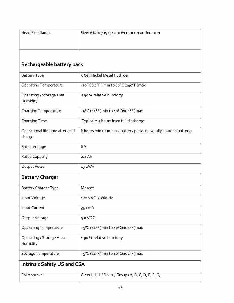
Head Size Range Size: 6¾ to 7 ⁵∕₈ (540 to 61 mm circumference)
Rechargeable battery pack
Battery Type 5 Cell Nickel Metal Hydride
Operating Temperature -20°C (-4°F ) min to 60°C (140°F )max
Operating / Storage area
Humidity
≤ 90 % relative humidity
Charging Temperature +5°C (41°F )min to 40°C(104°F )max
Charging Time Typical 2.5 hours from full discharge
Operational life time after a full
charge
6 hours minimum on 2 battery packs (new fully charged battery)
Rated Voltage 6 V
Rated Capacity 2.2 Ah
Output Power 13.2WH
Battery Charger
Battery Charger Type Mascot
Input Voltage 120 VAC, 50/60 Hz
Input Current 350 mA
Output Voltage 5.0 VDC
Operating Temperature +5°C (41°F )min to 40°C(104°F )max
Operating / Storage Area
Humidity
≤ 90 % relative humidity
Storage Temperature +5°C (41°F )min to 40°C(104°F )max
Intrinsic Safety US and CSA
FM Approval Class I, II, III / Div. 2 / Groups A, B, C, D, E, F, G,
42
** Supporting test data is available upon request from Gentex Corporation.
Returns or service
Please contact:
Gentex Corporation
324 Main St. Simpson PA 18407 Website: http://www.gentexcorp.com/ Telephone: (570) 282-3550
10. Service while under warranty:
All parts and labor will be covered for a period of 1 year from date of purchase. Contact Sales office for an
order number and shipping details.
11. Service after the warranty period
There will be an evaluation fee plus a charge for parts and labor. Contact Sales office for an order
number, shipping, and repair details.
43
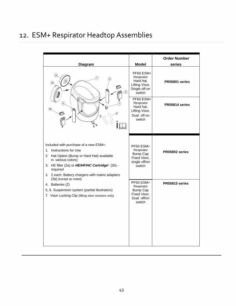
12. ESM+ Respirator Headtop Assemblies
Diagram
Model
Order Number
series
Included with purchase of a new ESM+:
1. Instructions for Use
2. Hat Option (Bump or Hard Hat) available in various colors)
3. HE filter (2a) or HE/HF/HC Cartridge* (2b) -required
3. 2 each: Battery chargers with mains adapters (3a) (except as noted)
4. Batteries (2)
5, 6. Suspension system (partial illustration)
7. Visor Locking Clip (lifting visor versions only)
PF60 ESM+ Respirator
Hard hat, Lifting Visor, Single off-on
switch
PR05801 series
PF60 ESM+ Respirator
Hard hat, Lifting Visor,
Dual off-on switch
PR05814 series
PF50 ESM+ Respirator
Bump Cap Fixed Visor, single off/on
switch
60ESM+ Respirator
Hard Hat ANSI Z89.1
Lift-able Visor
PR05802 series
PF50 ESM+ Respirator
Bump Cap Fixed Visor, Dual off/on
switch
PR05815 series
44
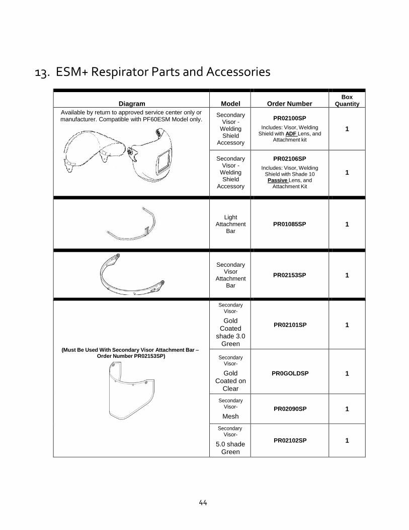
13. ESM+ Respirator Parts and Accessories
Diagram
Model
Order Number Box
Quantity
Available by return to approved service center only or manufacturer. Compatible with PF60ESM Model only.
Secondary Visor -
Welding Shield
Accessory
PR02100SP
Includes: Visor, Welding Shield with ADF Lens, and
Attachment kit
1
Secondary Visor -
Welding Shield
Accessory
PR02106SP
Includes: Visor, Welding Shield with Shade 10 Passive Lens, and
Attachment Kit
1
Light
Attachment Bar
PR01085SP
1
Secondary
Visor Attachment
Bar
PR02153SP
1
(Must Be Used With Secondary Visor Attachment Bar –
Order Number PR02153SP)
Secondary Visor-
Gold Coated
shade 3.0 Green
PR02101SP
1
Secondary Visor-
Gold Coated on
Clear
PR0GOLDSP
1
Secondary Visor-
Mesh
PR02090SP
1
Secondary Visor-
5.0 shade Green
PR02102SP
1
45
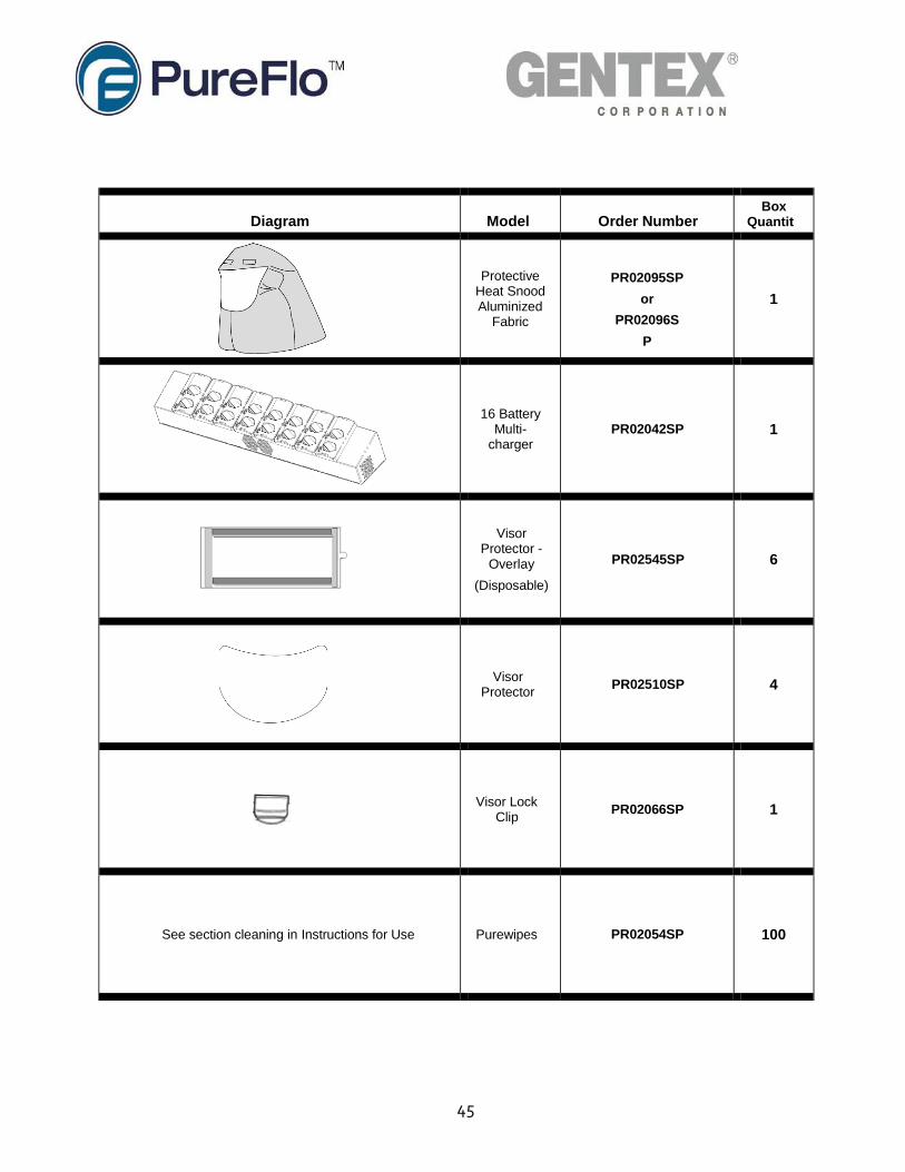
Diagram
Model
Order Number Box
Quantity
Protective Heat Snood Aluminized
Fabric
PR02095SP
or
PR02096S
P
1
16 Battery Multi-
charger
PR02042SP
1
Visor Protector -
Overlay
(Disposable)
PR02545SP
6
Visor Protector
PR02510SP
4
Visor Lock Clip
PR02066SP
1
See section cleaning in Instructions for Use
Purewipes
PR02054SP
100
46
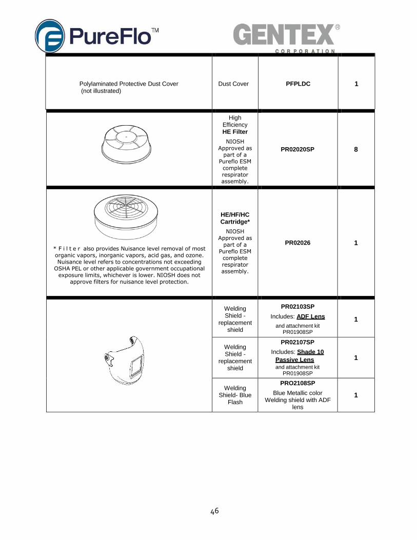
Polylaminated Protective Dust Cover (not illustrated)
Dust Cover
PFPLDC
1
High Efficiency HE Filter
NIOSH Approved as
part of a Pureflo ESM complete respirator assembly.
PR02020SP
8
* F i l t e r also provides Nuisance level removal of most organic vapors, inorganic vapors, acid gas, and ozone. Nuisance level refers to concentrations not exceeding
OSHA PEL or other applicable government occupational exposure limits, whichever is lower. NIOSH does not
approve filters for nuisance level protection.
HE/HF/HC Cartridge*
NIOSH Approved as
part of a Pureflo ESM complete respirator assembly.
PR02026
1
Welding Shield -
replacement shield
PR02103SP
Includes: ADF Lens
and attachment kit PR01908SP
1
Welding Shield -
replacement shield
PR02107SP
Includes: Shade 10
Passive Lens and attachment kit
PR01908SP
1
Welding Shield- Blue
Flash
PRO2108SP
Blue Metallic color Welding shield with ADF
lens
1
47
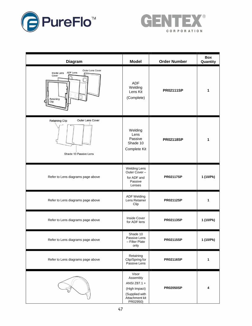
Diagram
Model
Order Number Box
Quantity
ADF
Welding Lens Kit
(Complete)
PR02111SP
1
Welding Lens
Passive Shade 10
Complete Kit
PR02118SP
1
Refer to Lens diagrams page above
Welding Lens Outer Cover –
for ADF and Passive Lenses
PR02117SP
1 (10/Pk)
Refer to Lens diagrams page above ADF Welding Lens Retainer
Clip
PR02112SP
1
Refer to Lens diagrams page above
Inside Cover for ADF lens
PR02113SP
1 (10/Pk)
Refer to Lens diagrams page above
Shade 10 Passive Lens – Filter Plate
only
PR02115SP
1 (10/Pk)
Refer to Lens diagrams page above Retaining
Clip/Spring for Passive Lens
PR02116SP
1
Visor Assembly
ANSI Z87.1 +
(High Impact)
(Supplied with Attachment kit
PR02950)
PR02050SP
4
48
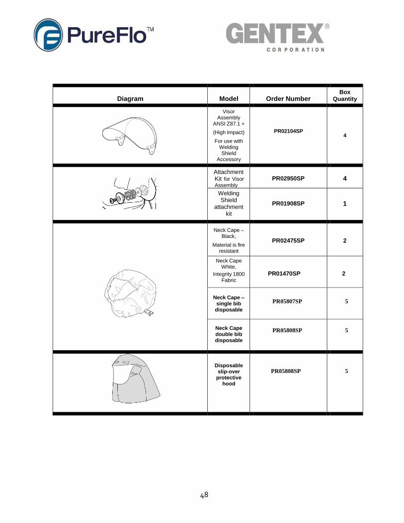
Diagram
Model
Order Number Box
Quantity
Visor Assembly
ANSI Z87.1 +
(High Impact)
For use with Welding Shield
Accessory
PR02104SP
4
Attachment Kit for Visor
Assembly
PR02950SP
4
Welding Shield
attachment kit
PR01908SP
1
Neck Cape – Black,
Material is fire resistant
PR02475SP
2
Neck Cape White,
Integrity 1800 Fabric
PR01470SP
2
Neck Cape – single bib disposable
PR05807SP
5
Neck Cape double bib disposable
PR05808SP 5
Disposable slip-over
protective hood
PR05808SP
5
49
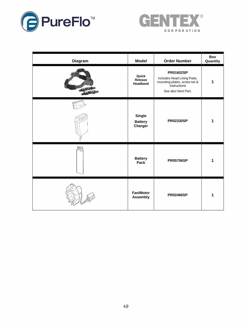
Diagram
Model
Order Number Box
Quantity
Quick
Release Headband
PR01602SP
includes Head Lining Pads, mounting plates, screw set &
instructions
See also Next Part.
1
Single
Battery Charger
PR02330SP
1
Battery Pack
PR05706SP
1
Fan/Motor Assembly
PR02466SP
1
50
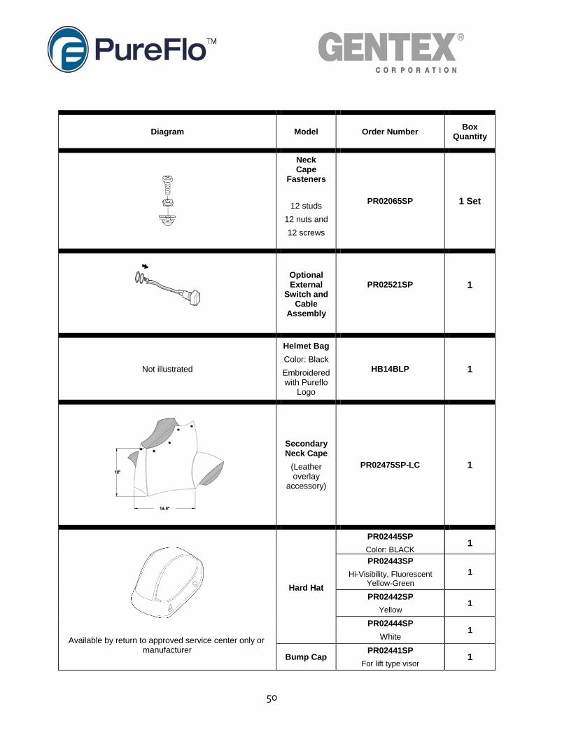
Diagram
Model
Order Number
Box Quantity
Neck Cape
Fasteners
12 studs
12 nuts and
12 screws
PR02065SP
1 Set
Optional External
Switch and Cable
Assembly
PR02521SP
1
Not illustrated
Helmet Bag
Color: Black
Embroidered with Pureflo
Logo
HB14BLP
1
Secondary Neck Cape
(Leather overlay
accessory)
PR02475SP-LC
1
Available by return to approved service center only or manufacturer
Hard Hat
PR02445SP
Color: BLACK 1
PR02443SP
Hi-Visibility, Fluorescent Yellow-Green
1
PR02442SP
Yellow
1
PR02444SP
White
1
Bump Cap PR02441SP
For lift type visor 1
51
14. ESM+ NIOSH Respirator Approval Label
NIOSH RESPIRATOR APPROVAL LABEL HERE