iffls8hr - docs.natlswgr.com
TRANSCRIPT
INSTRUCTIONS GEI-19008F
FREQUENCY RELAYS
£
TYPES' ' HU v *WA SSls las: .
IJF51A, IJF51B,and IJF52A nj x
,*?*1'
;S- i- jif
Pr =' m .
w
52^ **»•-WX.
KifflS8HR|||fiitiSUrn*mu« : l: 5 - ?• f• -:-
? & i i si ' - • ’• " C k ( $y
y;s r>*
G E N E R A L ® E L E C T R I C

Frequency Relays Type UFGEI-19008
1>4'
-4" JESSS? — «• i-r~i a>H >\ <\a#5 oI _ STATIONARY BRUSHAND CONTACTASSEMBLY
CONTROL SPRINGAND ADJUSTINGRING
-4 Oc ]- — — ••
f *SEAL-INUNIT TAPSELECTORSEAL-IN _yUNIT
wl
»43 v coI CO•:
CMK <r13? Oi>. COHV.4-
;
- SHAFTDRAG MAGNET
TARGETMOVINGCONTACT DISK
ONLDoo>ow~~̂ oCO
CT>U-
Case (Front View)UF Relay Removed From
Fla. I Type
Ov£>OCT»OoCO
ADJUSTABLERESISTOR
CM
o>u~
OPERATINGCOIL
RESTRAINTCOIL
Case (Rear View)IJF Relay Removed From
F i g . 2 Type
2

FREQUENCY RELAYSTYPE IJF
INTRODUCTIONback of the case. The cases and cradles are soconstructed that the relay cannot be inserted in thecase upside down. The connecting plug, besidesmaking the electrical connections between the re-spective blocks of the cradle and case, also lockthe latch in place. The cover, which is fastened tothe case by thumbscrews, holds the connecting plugin place.
These are relays of the induction disk typeintended for the protection of apparatus against theeffects of overfrequency or underfrequency.
The Type IJF is an induction disk type relaymounted in a single unit drawout case. It has twoshaded-pole U -magnet type driving elements actingon opposite sides of the disk. One of these, theoperating element, is designed to drive the disk inthe direction to close the left contacts, and theother , the restraining element to drive the disk inthe contact-opening direction on relays having single-throw contacts and to close the right contacts onrelays having double-throw contacts,
shaft is restrained by a spiral spring, the principalpurpose of which is to hold the contacts open whenthe relay is de-energized. The motion of the diskis retarded by permanent magnets to give thecorrect time delay for closing the contacts.
There is a seal- in unit mounted to the left ofthe shaft on the Type UF51A and UF51B relays.The Type UF52A relay has a seal-in unit mountedon both sides of the shaft. This element lias itscoil in series and its contacts in parallel with themain contacts such that when the main contactsclose, the seal-in element picks up and seals in.When the seal-in element picks up it raises atarget into view which latches up and remainsexposed until released by pressing a button beneaththe lower left corner of the cover.
To draw out the relay unit the cover is firstremoved, and the plug drawn out. Shorting bars areprovided in the case to short the current transformercircuits.relay unit can be easily drawn out. To replace therelay unit, the reverse order is followed.
A separate testing plug can be inserted in placeof the connecting plug to test the relay in place onthe panel either from its own source of current andvoltage, or from other sources. Or , the relay unitcan be drawn out and replaced by another which hasbeen tested in the laboratory.
The latches are then released, and theThe disk
APPLICATIONThe Type UF frequency relays are recom-
mended for protection of synchronous apparatusagainst overspeed or underspeed conditions causedby loss of load in the case of generators, or loss ofsupply power in the case of motor and condensers.The relays can be used to operate protective de-vices, or to sound an alarm whenever the frequencyof the circuit varies by a predetermined amountabove or below normal.
The case is suitable for either surface orsemiflush panel mounting and an assortment ofhardware is provided for either mounting,
cover attaches to the case and also carries thereset mechanism when one is required,
cover screw has provision for a sealing wire.The case has studs or screw connections at
both ends or at the bottom only for the externalconnections.the relay units and the case studs are madethrough spring backed contact fingers mounted instationary molded inner and outer blocks betweenwhich nests a removable connecting plug whichcompletes the circuits. The outer blocks, attachedto the case, have the studs for the external con-nections, and the inner blocks have the terminalsfor the internal connections.
TheRATINGSEach
These relays are available in frequency ratingsfrom 25 to 60 cycles and voltage ratings of 115 and230 volts.
The current closing rating of the contacts is30 amperes for voltages not exceeding 250 volts.The current-carrying ratings are affected by theselection of the tap on the seal-in coil as indicatedin Table I.
The electrical connections between
TABLE I
Amperes, AC or DCFunction
0.2 Amp Tap2-Amp TapThe relay mechanism is mounted in a steelframework called the cradle and is a complete unitwith all leads being terminated at the inner block.This cradle is held firmly in the case with a latchat the top and the bottom and by a guide pin at the
5Tripping DutyCarry Continuously
300.33
These instructions do not purport to cover all details or variations in equipment nor to provide forevery possible contingency to be met in connection with installation, operation or maintenance.further information be desired or should particular problems arise which are not covered sufficiently forthe purchaser's purposes, the matter should be referred to the General Electric Company.
Should
To the extent required the products described herein meet applicable ANSI, IEEE and NEMA standards;but no such assurance is given with respect to local codes and ordinances because they vary greatly.
3

GEI-19008 Frequency Relays Type UF
R E L A Y A D J . T O C L O S E ( 1 1 5 V O L T S C O N S T A N TI N A L L T E S T S )
C U R V E N O .1 1 5 V - 6 1 C Y C L E S1 1 5 V - 6 3 C Y C L E S1 1 5 V - 6 5 C Y C L E S
12
TIME DIAL- ,53A.5
68
4 . 0r .̂067 *3-P
E OOR 3 . 5 3̂*
A JT66I5 3 . 0G cnT6 5 cnIM 2 . 5C LL.tY *C 54 SL e 2 . CE CS 0N63 002 1 . 5S
oo6 2 i1 .0
6 1 0 . 5Cn
u_•K060
67 6 963 6 4 6 5 66 68 7 06 280 6 140 60 100 120 1600 20 140FREQUENCYV O L T S
Fig. 3 Type IJF5IA Relay, Voltage-FrequencyCharacteristics
Fig. 4 Type IJF5IA Relay, Time-FrequencyCharacteristies
60 (ns wxTscoteumW AU. JESTS)
ELAT ACd TO CLOSELS V - IS CYCLESn j v - 5JCTCUS111 v - »CYCLES
CLBVE NUMBER
irif* - asi
59 L5
SO
565.5
VO5710 r~
oor̂« s iC 56\JY
C 3Z*D
L LOE 55S g CT>is
lLL.2
54 10¥N Ii 2.S CNJo53
<T>u> rr/ oo52 *r1.5
I
I.o
51 vO.. ,_J05 -- C7)
i
LL.50 -k16060 80 100 120 1400 20 40 50 ' 51" 52 " S3 54 55" 'Sfc 5^CYCLESVOLTS
Fig. 6Fig. 5 Type IJF5IB Relay, Voltage-FrequencyCharacteristics
Type IJF5IB Relay, Time-FrequencyCharacter!sties
4Indicates Revision

Frequency Relays Type IJF GEI-19008
BURDENSThe 2-ampere tap has a d-c resistance of 0.13ohms and a 60 cycle impedance of 0.53 ohms whilethe 0.2-ampere tap has a 7 ohm d-c resistance anda 52 ohm 60 cycle impedance. The tap setting usedon the seal-in element is determined by the currentdrawn by the trip coil.
Burden data for the 55-60 cycle under frequencyrelay and 60-65 cycles overfrequency relays aregiven in Table I at 115 volts 60 cycles.
Burdens listed are total burden of relay.TABLE nThe 0.2-ampere tap is for use with trip coils
that operate on currents ranging from 0.2 up to 2.0amperes at the minimum control voltage. If thistap is used with trip coils requiring more than 2amperes, there is a possibility that the 7-ohmresistance will reduce the current to so low a valuethat the breaker will not be tripped.
Volt PowerFactorRelay WattsAmps
UF51AUF51B
8.7 .99 8.65.8 .98 5.7
Total burdens for the Type UF52A relay at115 volts are as follows:The 2-ampere tap should be used with trip coils
that take 2 amperes or more at minimum controlvoltage, provided the tripping current does notexceed 30 amperes at the maximum control voltage.If the tripping current exceeds 30 amperes anauxiliary relay should be used, the connectionsbeing such that the tripping current does not passthrough the contacts or the target and seal-in coilsof the protective relay.
TABLE HI
PowerFactor
VoltFreq. WattsAmps
6.325 .95 660 10.7 .89 9.5
RECEIVING, HANDLING AND STORAGEpacking the relay in order that none of the parts areinjured or the adjustments disturbed.These relays, when not included as a part of a
control panel, will be shipped in cartons designed toprotect them against damage. Immediately uponreceipt of the relay, an examination should be madefor any damage sustained during shipment. If injuryor damage resulting from rough handling is evident,a claim should be filed at once with the transportationcompany and the nearest Sales Office of the GeneralElectric Company notified promptly.
Reasonable care should be exercised in un-
If the relays are not to be installed immediately,they should be stored in their original cartons in aplace that is free from moisture, dust, and metallicchips. Foreign matter collected on the outside ofthe case may find its way inside when the cover isremoved and cause trouble in the operation of therelay.
INSTALLATIONAUXILIARIES
When external capacitors, and in some casesresistors, are furnished with relays they are iden-tified by means of serial numbers. These numbersare of the form KX-1023 or OA-2155. The purposeof these numbers is to insure that each relay, wheninstalled, will be provided with the same auxiliarieswith which it was calibrated at the factory.
The reason for this precaution is to eliminatethe variation in calibrations of the relays whichwould otherwise result from the variation in elec-trical properties of the auxiliaries.
LOCATIONThe location should be clean and dry, free from
dust and excessive vibration, and well lighted tofacilitate inspection and testing.
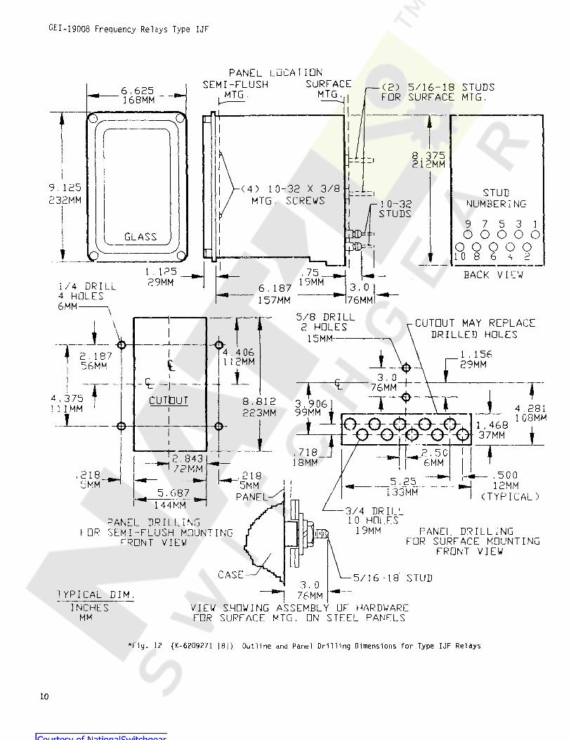
MOUNTINGThe relay should be mounted on a vertical
surface. The outline and panel diagram is shownin Fig. 12.
CONNECTIONSADJUSTMENTSInternal connection diagrams for the various
relay types are shown in Fig. 7 to 9 inclusive.Typical wiring diagrams are given in Fig.10and 11.
One of the mounting studs or screws should bepermanently grounded by a conductor not less thanNo. 12 B&S gage copper wire or its equivalent.
TARGET AND SEAL-IN ELEMENTFor trip coils operating on currents ranging
from 0.2 up to 2.0 amperes at the minimum controlvoltage, set the target and seal-in tap plug in the0.2-ampere tap.
5

GEI-19G08 Frequency Relays Type UF
PICKUPFor trip coils operating on currents rangingfrom 2 to 30 amperes at the minimum controlvoltage, place the tap plug in the 2-ampere tap. Pickup of the relays can be set for any frequency
from minimum to maximum values inclusive as shownin Tables IV, V and VI.
To make the setting, apply the desiredfrequencyat rated volts to the relay and adjust the resistoruntil the relay just picks up. The relay mustbe in the case for an accurate check of the operatingpoint.
The tap screw is the screw holding the right-hand stationary contact of the seal-in unit. Tochange the tap setting, first remove the connectingplug. Then take a screw from the left-hand stationarycontact and place it in the desired tap. Next, removethe screw from the other tap, and place it inthe left-hand contact. This procedure is necessaryto prevent the right-hand stationary contact fromgetting out of adjustment. Screws should not bein both taps at the same time as pickup for d-cwill be the higher tap value.
The relay is adjusted at the factory to have thepickup called for on the requisition or, if pickupis not specified, at the applicable nominal valueshown in Tables IV, V and VI.
TABLE IV PICKUP CALIBRATION - IJF51A RELAY
RELAYMODEL
CALIBRATION-CYCLES TO CLOSE LEFT CONTACTRATEDNOMINALFREQUENCYVOLTS MINIMUM MAXIMUM
f IJF51A1A: IJF51A2A! IJF51A3A1 IJF51A4A
1JF51 A5AF51 A6A
IJF51A7A
63115 6560HZ 61;
58115 6060HZ 5753115 555160HZ70115 7560HZ 6547115 45 4960HZ
r i 115 444660HZ 38> i U
115 606260HZ 58
IJF51A9A! I0 F51 A10A
j IJF51 A11Ai I0 F51 A12Ai IJF5U13A
115 165 159150HZ 153i115 6560HZ 7060115 6160HZ 55 65115 140HZ
160HZ155 148143
115 167172162
TABLE V PICKUP CALIBRATION - IJF51 B RELAY
CALIBRATION-CYCLES TO CLOSE LEFT CONTACTRELAYMODEL
RATEDNOMINALMAXIMUMVOLTS FREQUENCY MINIMUM
45IJF51B1AIJF51B 2AIJF51 B3AIJF51 B4AIJF51 B5A
115 60HZ115 5760HZ 5955115 474950HZ 45115 23.524.525HZ 22.5
52115 5560HZ 48
47IJF51 B7Ai IJF51 B8A
220 4950HZ 4555115 6060HZ 50
TABLE VI PICKUP CALIBRATION . - IJF52A RELAY
RIGHT CONTACT CLOSES( CYCLES ABOVE LEFT )
MAXIMUM- !RELAYMODEL
RATED CYCLES TO CLOSE LEFT CONTACTFREQUENCY MINI MUM i MAXIMUM NOMINALVOLTS MINIMUM
IJF52A1 AIJF52A2AIJF52A3AIJF52A4A
1 . 0115 0.42525HZ 23 271 .00.4230 25HZ 2523 272 . 0115 0 . 850HZ 51 50492 . 00.75115 65 5960HZ 55
0

Frequency Relays Type UF GEI-19008
usually difficult, in the field, to obtain odd fre-quencies for checking the pick-up time,precaution then against having the time dial ac-cidentally disturbed with no means available forresetting it, the time dial is locked in position atthe factory to give the desired time. If it isdesired to change the position of the time dial,this may be done by loosening the 2 screws throughthe frame just above the dial. Turning the dialcounter-clockwise (top view) increases the contacttravel and hence the time. Tighten the screws whenthe setting has been completed.
TIME As aOperating time of the relay for a given condi-
tion m determined by the position of the drag magneton its shelf. Moving the drag magnet toward thedisk shaft decrease pick-up time while moving itaway from the disk shaft increases pick-up time.
Normally the time dial at the top of the diskshaft is readily adjustable with the fingers to giveany time delay desired, within certain limits. It is
PRINCIPLES OF OPERATIONThe Type UF51A relay is an overfrequency
relay having a single-circuit normally open contactwhich closes on overfrequency.
The Type UF51B relay is an underfrequencyrelay having a single-circuit normally open contactwhich closes on underfrequency.
The Type UF52A relay is an overfrequency andunderfrequency relay having double throw contacts,The left contacts close on underfrequency and theright contacts close on overfrequency.
Discrimination between normal frequency andabnormal frequency is accomplished by the oppositevariation in impedance with frequency of two cir-cuits, one circuit containing the coil of one U-magnetconnected directly to the voltage supply and desig-nated as the inductive circuit, the other circuitcontaining the coil of the remaining U-magnet inseries with an external capacitor connected to thesame supply voltage and designated as the capacitivecircuit, because the capacitive reactance predomi-nates at normal frequency.
In the underfrequency relay, the coil of theoperating U-magnet composes the inductive circuit,and the coil of the restraining U-magnet in serieswith the capacitor composes the capacitive circuit.
At normal frequency the torque produced by thecurrent through the capacitive circuit (restrainingU-magnet) is greater than the torque produced bythe current (operating U-magnet). A decrease inthe frequency of the supply voltage is accompaniedby a decrease in the impedance of the inductivecircuit permitting an increase of the operatingcurrent, while the impedance of the capacitive cir-cuit increases, thereby reducing the restrainingcurrent. Thus as the supply frequency is decreasedthe operating U-magnet overcomes die restrainingU-magnet and the relay operates.
The overfrequency relay differs from the under-frequency relay in that the operating U-magnet coilis in the capacitive circuit and the? restraining U-magnet coil forms the inductive circuit,sequently, the torque of the inductive element isadjusted to preponderate at normal frequency.
Voltage-frequency characteristics are shownin Fig. 3 for the 60 cycle LJF overfrequency relays.Fig. 5 shows the voltage-frequency characteristicsof the 60 cycle UF undervoltage relay.
Time-frequency characteristics for the 60cycleUF overfrequency relays are shown in Fig.4. Timefrequency curves for the 60cycle UF underfrequencyrelays are shown in Fig. 6,
Con-
MAINTENANCECONTACT CLEANINGThe relays are adjusted at the factory and it is
advisable not to disturb the adjustments. If for anyreason, they have been disturbed, the followingpoints should be observed in restoring them:
For cleaning fine silver contacts, a flexibleburnishing tool should be used. This consists of aflexible strip of metal with an etched roughenedsurface, resembling in effect a superfine file. Thepolishing action is so delicate that no scratches areleft, yet corroded material will be removed rapidlyand thoroughly. The flexibility of the tool insuresthe cleaning of the actual points of contact.
Fine silver contacts should not be cleaned withknives, files ,, or abrasive paper or cloth. Knivescr files may leave scratches which increase arcingand deterioration of the contacts- Abrasive paperor cloth may leave minute particles of insulatingabrasive material in the contacts and thus preventclosing.
DISK AND BEARINGS
The lower jewel may be tested for cracks byexploring its surface with the point of a fine needle.If it is necessary to replace the jewel a new pivotshould be screwed into the bottom of the shaft atthe same lime. The jewel should be turned up untilthe disk is centered in the air gaps, after which itshould be locked in this position by the setscrewpro /ided for this purpose. The upper bearing pinshould next be adjusted until very little end play canbe felt between the pin and the steel ball in therecess at the top of the shaft; about 0.015 inch iscorrect. The burnishing tool described is included in the
standard relay tool kit obtainable from the factory.7

GEI-1900ft Frequency Relays Type IJF
\RESTRAINING
COILOPERATING
COIL
rflSEAL**INUNIT m OPERATING
COIL > RESTRAININGCOIL
S SEAL-INUNITt
\ t * v* \ t \ f
I|V
I5
v
* *\ t -¥ \ f % v X /
I1
V v VI7
1
6 B
• » SHORT FINGER5
2 6 8
* sr SHORT FINGER
(K-6306813 [ 2 ] ) Type IJF51A Relay, InternalConnections (Front View)
Fig. 8 ( K-6306616) Type IJF51B Relay, InternalConnections (Front View)
*Fig. 7
DOMINANTCOIL ATHIGH FREQ.
DOMINANTCOIL ATLOW FREQ. I
T R I P B U S2 W
3HIGH FREQ.r CONTACTS
LLOW FREO.[-CONTACTS
/ EXTERNAL CAPACITOR
T?SEAL- INU N I T
SEAL- IbUNIT
EXTERNALRES. ( WHENUSED )
H X .i t 7
f t6 9
i-Ia / OVER-FREQUENCY RELAYS
TYPE iJF51A
T R I P C l R C U I T F O R I J F5I BS A M E A S A B O V E.
DEVICE FUNCTION NUMBERS52 - CIRCUIT 8REAKER81 - PRECUENCY RELAY.TYPE Uf
a - AOX.CONTACT.CLOSED WHENBREAKER IS CLOSEDOPERATING COIL
RC - RESTRAINT COILTR19 COIL
EXTERNAL RES.(»H£N USED j
A27 1 oc
TCV * V * V * \ f m
V VS 'X / V.
K7-kv i
7
VVVY6 8.
1—
ibj UNDER-FREQUENCY RELAYSTYPE IJF51B5 9
*2 6 108
* = SHORT FINGER
*Fig. 9 (K-6400202 \ 2 \ ) Type IJF52A Relay, InternalConnections, (Front View)
Fig. 10 ( K-6154254-3 ) Typical External ConnectionsFor The Type IJF51A and IJF51B Relays
8* Indicates Revision
Frequency Relays Type IJF GFI-19008
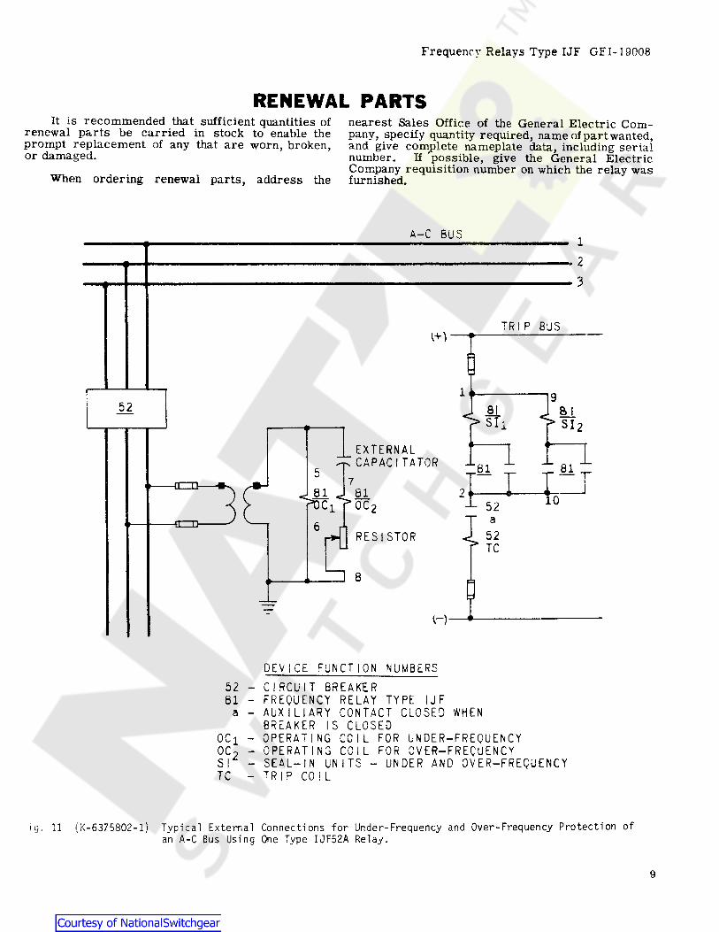
RENEWAL PARTSIt is recommended that sufficient quantities of
renewal parts be carried in stock to enable theprompt replacement of any that are worn, broken,or damaged.
nearest Sales Office of the General Electric Com-pany, specify quantity required, name of part wanted,and give complete nameplate data, including serialnumber. If possible, give the General ElectricCompany requisition number on which the relay wasfurnished.When ordering renewal parts, address the
A-C B U S 123
T R I P B U SO')
95 2 SI a i
s i i S l 2*E X T E R N A LC A P A C I T A T O R 1 8 1 _“8 15 u7
8 1 8 1 2 'pDC1 fOC2105 2
1»r T C
6R E S I S T O R
H
D E V I C E F U N C T I O N N U M B E R S5 2 - C I R C U I T B R E A K E R8 1 - F R E Q U E N C Y R E L A Y T Y P E I J F
A U X I L I A R Y C O N T A C T C L O S E D W H E NB R E A K E R I S C L O S E D
O C i - O P E R A T I N G C O I L F O R U N D E R-F R E Q U E N C YO C, -sr -
a
O P E R A T I N G C O I L F O R O V E R-F R E Q U E N C YS E A L- I N U N I T S - U N D E R A N D O V E R-F R E Q U E N C YT R I P C O I LT C
ig , 11 ( K-6375802-1) Typical External Connections for Under-Frequency and Over-Frequency Protection ofan A-C Bus Using One Type IJF52A Relay .
9
GEI-19008 Frequency Relays Type IJF
PANEL LOCATIONSURFACESEMI-FLUSH ( 2) 5/16-18 STUDS
FDR SURFACE MTG .6 , 625168MM MTGMTGL
5
8 , 375212MM
9 , 125232MM
( 4 ) 10-32 X 3/8MTG , SCREWS
STUDNUMBERINGr 10-32
STUDS9 7 5 3 1o o o o o
o o o o o1 0 8 6 <r 2
::iGLASSL
1 . 12529MM
, 75 BACK VIEW19MM1/ 4 DRILL
4 HOLES3 , 06 , 187
157MM 76MM6MM5/8 DRILL2 HDLES
15MM1. 11 CUTDUT MAY REPLACE
DRILLED HDLES1 »\\
04.4 06I12MM) 1 . 1 5 6
29MM2 , 1 8 756MM -v\ r3 . 0 T \_JLi
-t -r -CUTt lUT
% 76MM ?* {4 , 3 7 51 1 1M M 18 . 8 1 2
223MM fI3.9 0699MM 4 . 2 8 1
1 08MMI t lOpGo^^G^M1, 4 6 837MM
o iI, 7 1 8
18M M2 . 5 C' 2 . 8 4 3
^ 72MM 6MM, 2 1 8 , 5 0 0
12MM( T Y P I C A L )
2 1 8 5 . 2 5133MM *15MM 5MM
5 , 6 8 71 44M M
PANEL3/ 4 DRILL10 HOLES
19MMPANEL DRILLING
FDR SEMI-FLUSH MOUNTINGFRDNT V I E W
PANEL DRILLINGFOR SURFACE MOUNTING
FRONT V I E W
i i i
5/ 1 6 - 1 8 STUD3 , 0
76MMVIEW SHOWING ASSEMBLY OF HARDWAREFOR SURFACE M T G . ON STEEL PANELS
T Y P I C A L D I M ,
INCHESMM
*Fig. 12 ( K-6209271 [ 81) Outl ine and Panel Dri l l ing Dimensions for Type IJF Relays
10


åååå*( 3RZHU 0DQDJHPHQW
215 Anderson AvenueMarkham, OntarioCanada L6E 1B3Tel: (905) 294-6222Fax: (905) 201-2098www.ge.com/indsys/pm