iewb sc vol i v5.section.1.asa.firewall final
TRANSCRIPT

CCIE Security Lab Workbook Volume I Version 5.0 ASA Firewall
Copyright © 2009 Internetwork Expert www.INE.comi
Copyright Information Copyright © 2009 Internetwork Expert, Inc. All rights reserved.
The following publication, CCIE Security Lab Workbook Volume I Version 5.0, was developed by Internetwork Expert, Inc. All rights reserved. No part of this publication may be reproduced or distributed in any form or by any means without the prior written permission of Internetwork Expert, Inc.
Cisco®, Cisco® Systems, CCIE, and Cisco Certified Internetwork Expert, are registered trademarks of Cisco® Systems, Inc. and/or its affiliates in the U.S. and certain countries.
All other products and company names are the trademarks, registered trademarks, and service marks of the respective owners. Throughout this manual, Internetwork Expert, Inc. has used its best efforts to distinguish proprietary trademarks from descriptive names by following the capitalization styles used by the manufacturer.

CCIE Security Lab Workbook Volume I Version 5.0 ASA Firewall
Copyright © 2009 Internetwork Expert www.INE.comii
Disclaimer
The following publication, CCIE Security Lab Workbook Volume I Version 5.0, is designed to assist candidates in the preparation for Cisco Systems’ CCIE Security Lab Exam. While every effort has been made to ensure that all material is as complete and accurate as possible, the enclosed material is presented on an “as is” basis. Neither the authors nor Internetwork Expert, Inc. assume any liability or responsibility to any person or entity with respect to loss or damages incurred from the information contained in this workbook.
This workbook was developed by Internetwork Expert, Inc. and is an original work of the aforementioned authors. Any similarities between material presented in this workbook and actual CCIE lab material is completely coincidental.

CCIE Security Lab Workbook Volume I Version 5.0 ASA Firewall
Copyright © 2009 Internetwork Expert www.INE.comiii
Table of Contents ASA Firewall ........................................................................................1
1.1 VLANs and IP Addressing ................................................................. 21.2 RIPv2................................................................................................. 21.3 OSPF................................................................................................. 21.4 EIGRP ............................................................................................... 21.5 Advanced Routing ............................................................................. 31.6 IP Access-Lists .................................................................................. 41.7 Object Groups ................................................................................... 51.8 Administrative Access ....................................................................... 51.9 ICMP Traffic....................................................................................... 51.10 URL Filtering.................................................................................... 51.11 Dynamic NAT and PAT ................................................................... 61.12 Static NAT and PAT ........................................................................ 61.13 Dynamic Policy NAT........................................................................ 61.14 Static Policy NAT and PAT.............................................................. 71.15 Identity NAT and NAT Exemption.................................................... 71.16 Outside Dynamic NAT ..................................................................... 71.17 DNS Doctoring using “Alias” ............................................................ 71.18 DNS Doctoring using “Static”........................................................... 81.19 Fragmented Traffic .......................................................................... 81.20 IDENT Issues................................................................................... 81.21 BGP across the Firewall .................................................................. 81.22 Stub Multicast Routing..................................................................... 81.23 PIM Multicast Routing...................................................................... 91.24 Network Time Protocol .................................................................... 91.25 System Logging............................................................................... 91.26 Filtering System Logs ...................................................................... 91.27 SNMP Monitoring .......................................................................... 101.28 DHCP Server ................................................................................. 101.29 HTTP Traffic Inspection................................................................. 101.30 FTP Traffic Inspection ................................................................... 111.31 SMTP Traffic Inspection ................................................................ 111.32 TCP Inspection .............................................................................. 111.33 Management Traffic Inspection ..................................................... 121.34 ICMP Traffic Inspection ................................................................. 121.35 Threat Detection ............................................................................ 121.36 Un-Stealthing the Firewall ............................................................. 121.37 Traffic Policing ............................................................................... 131.38 Low Latency Queuing.................................................................... 131.39 Traffic Shaping .............................................................................. 131.40 Hierarchical Queuing ..................................................................... 141.41 Transparent Firewall ...................................................................... 141.42 ARP Inspection.............................................................................. 14

CCIE Security Lab Workbook Volume I Version 5.0 ASA Firewall
Copyright © 2009 Internetwork Expert www.INE.comiv
1.43 Ethertype Access-Lists .................................................................. 151.44 Transparent Firewall NAT.............................................................. 151.45 Firewall Contexts ........................................................................... 151.46 Firewall Contexts Routing.............................................................. 161.47 Firewall Contexts Classification..................................................... 161.48 Resource Management ................................................................. 161.49 Active/Standby Failover ................................................................. 171.50 Active/Active Failover .................................................................... 181.51 ASA Redundant Interface.............................................................. 191.52 ASA Enhanced Object Groups ...................................................... 19
ASA Firewall Solutions ......................................................................201.1 VLANs and IP Addressing ............................................................... 201.2 Configuring RIPv2 ........................................................................... 241.3 Configuring OSPF ........................................................................... 281.4 EIGRP ............................................................................................. 321.5 Advanced Routing ........................................................................... 351.6 IP Access-Lists ................................................................................ 401.7 Object Groups ................................................................................. 461.8 Administrative Access ..................................................................... 491.9 ICMP Traffic..................................................................................... 531.10 URL Filtering.................................................................................. 561.11 Dynamic NAT and PAT ................................................................. 591.12 Static NAT and PAT ...................................................................... 651.13 Dynamic Policy NAT...................................................................... 711.14 Static Policy NAT and PAT............................................................ 741.15 Identity NAT and NAT Exemption.................................................. 771.16 Outside Dynamic NAT ................................................................... 811.17 DNS Doctoring using “Alias” .......................................................... 841.18 DNS Doctoring using “Static”......................................................... 891.19 Fragmented Traffic ........................................................................ 911.20 Handling IDENT Issues ................................................................. 931.21 BGP across the Firewall ................................................................ 951.22 Stub Multicast Routing................................................................... 981.23 PIM Multicast Routing.................................................................. 1011.24 Network Time Protocol ................................................................ 1071.25 System Logging........................................................................... 1091.26 Filtering System Logs .................................................................. 1131.27 SNMP Monitoring ........................................................................ 1151.28 DHCP Server ............................................................................... 1171.29 HTTP Traffic Inspection............................................................... 1201.30 FTP Traffic Inspection ................................................................. 1251.31 SMTP Traffic Inspection .............................................................. 1311.32 TCP Inspection ............................................................................ 1341.33 Management Traffic Inspection ................................................... 1371.34 ICMP Traffic Inspection ............................................................... 139

CCIE Security Lab Workbook Volume I Version 5.0 ASA Firewall
Copyright © 2009 Internetwork Expert www.INE.comv
1.35 Threat Detection .......................................................................... 1421.36 Un-Stealthing the Firewall ........................................................... 1451.37 Traffic Policing ............................................................................. 1471.38 Low Latency Queuing.................................................................. 1501.39 Traffic Shaping ............................................................................ 1531.40 Hierarchical Queuing ................................................................... 1571.41 Transparent Firewall .................................................................... 1601.42 ARP Inspection............................................................................ 1651.43 Ethertype Access-Lists ................................................................ 1671.44 Transparent Firewall NAT............................................................ 1701.45 Firewall Contexts ......................................................................... 1721.46 Firewall Contexts Routing............................................................ 1771.47 Firewall Contexts Classification................................................... 1791.48 Resource Management ............................................................... 1841.49 Active/Standby Failover ............................................................... 1891.50 Active/Active Failover .................................................................. 1961.51 ASA Redundant Interfaces .......................................................... 2031.52 ASA Enhanced Object Groups .................................................... 207

CCIE Security Lab Workbook Volume I Version 5.0 ASA Firewall
Copyright © 2009 Internetwork Expert www.INE.com1
ASA Firewall
Note
Load the ASA Routing files to initialize your rack. Use the following diagram as your reference when working with the tasks below.

CCIE Security Lab Workbook Volume I Version 5.0 ASA Firewall
Copyright © 2009 Internetwork Expert www.INE.com2
1.1 VLANs and IP Addressing • Configure ASA1’s interface Ethernet 0/0 using the nameif “outside” and
the security level of zero. • Configure ASA1’s interface Ethernet 0/1 using the nameif “inside” and the
security level value of 100. • Create new subinterface Ethernet 0/2.120 using the VLAN number 120,
nameif “dmz1” and the security-level of 75. • Create new subinterface Ethernet 0/2.124 using the VLAN number 124,
nameif “dmz2” and the security-level of 50. • Configure interface IP addressing per the diagram.
1.2 RIPv2 • Enable RIPv2 on ASA1 for networks 10.0.0.0/8 and 136.1.0.0/16. • Ensure routing summaries are not generated automatically on the classful
subnets boundaries. • Do not send RIPv2 updates out of any interfaces except to “Inside” and
“DMZ1”. • Configure RIPv2 on R1 using the network 136.1.0.0/16. • Authenticate RIPv2 updates sent/received to/from R1 using the key-string
“CISCO”. • Use the most secure form of authentication.
1.3 OSPF • Create OSPF routing process in the ASA firewall using the OSPF process
ID 1 and the OSPF router-ID of 150.X.12.12.2. • Assign interfaces to OSPF areas per the diagram provided. • Ensure the ASA is never elected as DR on both segments. • Authenticate the OSPF adjacency across “DMZ2” interface using
interface-level commands only. Use the password of “CISCO” and most secure form of authentication.
• Configure the less secure form of OSPF authentication on the interface “Outside”. Use only process-level commands for this along with the password of “CISCO”.
1.4 EIGRP • Disable OSPF on the connection to R4 and configure EIGRP instead. • Authenticate the EIGRP adjacency using the password value of CISCO.

CCIE Security Lab Workbook Volume I Version 5.0 ASA Firewall
Copyright © 2009 Internetwork Expert www.INE.com3
1.5 Advanced Routing • Redistribute RIP and EIGRP routes into OSPF. • Implement a reliable default route towards R2 in the firewall. Track R2’s
Loopback0 reachability for that. • Use R3 as the backup default gateway. • Originate the default route into RIPv2 and EIGRP.

CCIE Security Lab Workbook Volume I Version 5.0 ASA Firewall
Copyright © 2009 Internetwork Expert www.INE.com4
Note
At this point, erase running configurations on all devices in the racks. Load the ASA Access Control initial configurations. Refer to the following diagram when working with the scenarios below.
1.6 IP Access-Lists • Implement the access policy outlined below. • Permit the following incoming traffic:
o Incoming ping requests and replied to pings from the inside. o FTP/HTTP/NTP traffic to AAA/CA server o Returning traffic for the UNIX-style traceroute command.
• Permit the following types of outgoing traffic:
o Pings and replies to the pings sent from the outside. o Outgoing packets for the UNIX-style traceroute command. o Outgoing telnet, FTP, HTTP traffic
• . Use just two access-list named OUTSIDE_IN and OUTSIDE_OUT applied ingress and egress to the “Outside” interface.

CCIE Security Lab Workbook Volume I Version 5.0 ASA Firewall
Copyright © 2009 Internetwork Expert www.INE.com5
1.7 Object Groups • Create the following object groups:
o SERVERS containing the host 10.0.0.100. o ROUTERS containing network 136.X.121.0/24 to it. o COMMON_ICMP containing the ICMP types corresponding to the
ping and UNIX-style traceroute commands. o TRC_PORTS containing the range of UDP ports 33434-33464. o SERVER_PORTS containing TCP ports for HTTP and FTP. o ROUTER_PORTS and add TCP ports corresponding to
Telnet/SSH in addition to port 7001 to the group.
• Reduce the size of the previously created access-lists using the object groups just created.
1.8 Administrative Access • Permit telnet access to the ASA unit from the inside subnet
(136.X.121.0/24). • Permit ssh access to the ASA unit from the outside subnet
(136.X.122.0/24). • Permit users to access the ASDM feature from host 10.0.0.100.
1.9 ICMP Traffic • Configure the firewall such that no one could ping it. However, make sure
firewall itself is able to ping anyone. • Additionally, make sure that pMTU discovery and traceroute work
successfully from the firewall. • All other ICMP messages terminating on firewall interfaces should be
discarded.
1.10 URL Filtering • Filter ActiveX and JavaScript from all HTTP requests on port 80. • Configure the ASA to use Websense URL filtering server at 10.0.0.100. • Filter HTTP URL from 136.X.121.0/24 network on ports 80 and 8080.
Block proxy-requests going on port 8080. • Additionally, configure FTP filtering on port 21 for network 136.X.121.0/24.
Deny interactive FTP connections. • In case of the URL server failure, HTTP/FTP requests should be allowed.

CCIE Security Lab Workbook Volume I Version 5.0 ASA Firewall
Copyright © 2009 Internetwork Expert www.INE.com6
Note
At this point, enable NAT-control in the firewall and make RIPv2 passive on the outside interface of the ASA firewall:
ASA1: nat-control ! router rip passive-interface outside
1.11 Dynamic NAT and PAT • Configure NAT such that hosts on the inside going to outside have
their addresses translated into address pool 136.X.122.100-110. Use interface IP address as PAT backup.
• Configure NAT such that hosts on the DMZ going to outside have their addresses translated into address pool 136.X.122.200-210. Use the last IP address in the range as PAT backup.
• Configure NAT such that hosts on the inside going into DMZ have their addresses translated into interface IP address via PAT.
1.12 Static NAT and PAT • Clear any previous NAT rules if needed. • Map the DMZ IP address 10.0.0.100 to the outside 136.X.122.100. • Configure Static PAT such that telnet sessions to the outside interface are
redirected to R1. • Configure Static PAT such that DNS requests sent to the ASA inside
interface are redirected to R2. Make sure inside hosts are translated when they go outside.
1.13 Dynamic Policy NAT • Clear any previous NAT rules if needed. • Telnet connections going outside should be PAT translated using the IP
address 136.X.122.100 • ICMP packets going outside should be PAT translated using the IP
address 136.X.122.101 • Use the access-lists TELNET and ICMP to distinguish two types of traffic. • Everything else should be PAT translated using the outside interface IP.
CCIE Security Lab Workbook Volume I Version 5.0 ASA Firewall
Copyright © 2009 Internetwork Expert www.INE.com7
1.14 Static Policy NAT and PAT • Clear any previous NAT rules if needed. • Redirect telnet connections going from 136.X.122.0/24 to the firewall
outside interface to R1. • Redirect HTTP connections going from 150.X.2.0/24 subnet of R2 to the
firewall outside interface to AAA/CA server. • Create and apply the necessary access-group to the outside interface.
1.15 Identity NAT and NAT Exemption • Clear any previous NAT rules if needed and re-enable RIPv2 announces
on the outside interface of the firewall. • Configure the firewall such that the network 136.X.121.0/24 is translated
to itself. • Configure the firewall so that no NAT translation is performed for the
AAA/CA server 10.0.0.100.
1.16 Outside Dynamic NAT • Prevent R1 from learning about the outside destinations via RIP. • Hosts from the outside with the source IP addresses from the subnet
136.X.122.0/24 accessing the hosts on the inside should have their IP addresses translated using the inside interface IP address.
• Ensure that hosts on the inside are still able to access the AAA/CA server on the DMZ interface.
1.17 DNS Doctoring using “Alias” • Clear any previously configured address translation rules. • Configure R2 to act as DNS server. Create a new host entry for the name
“WWW” with address 136.X.122.100. • Hosts on the DMZ subnet using R2 as their DNS server should see the
name “WWW” resolved to the IP address of the AAA/CA server. • Use the “alias” command in the ASA to accomplish this.

CCIE Security Lab Workbook Volume I Version 5.0 ASA Firewall
Copyright © 2009 Internetwork Expert www.INE.com8
1.18 DNS Doctoring using “Static” • Modify the solution of the previous task to use the “static” command
instead of the legacy “alias”.
1.19 Fragmented Traffic • Permit ICMP traffic through the firewall. • Disable the fragmented packets on all interfaces.
1.20 IDENT Issues • Configure the firewall to quickly terminate the IDENT lookup sessions
going from outside for TCP sessions initiated by inside users. • Consider both users translated to NAT pools and the outside interface IP
address.
1.21 BGP across the Firewall • Ensure the ASA firewall runs in NAT controlled mode and RIPv2 is active
on all interfaces. • R1 and R2 are pre-configured to peer eBGP across the firewall. • Both routers use their Loopback0 interfaces to source the BGP session. • Authenticate the BGP session using the password of “CISCO”. • Ensure that R2 is allowed to initiate a BGP sessions to R1.
1.22 Stub Multicast Routing • The ASA firewall connects stub multicast area on the “Inside” interface to
the multicast-capable network behind R2. • Configure the appliance to act as a proxy agent for IGMP join/leave
messages sent from R2. • Ensure the RPF interface for unknown destinations is the outside
interface. • On R1, join the Ethernet interface to group 239.0.0.1 and make sure R2
can ping it.

CCIE Security Lab Workbook Volume I Version 5.0 ASA Firewall
Copyright © 2009 Internetwork Expert www.INE.com9
1.23 PIM Multicast Routing • Remove the stub multicast routing configuration and enable PIM on the
outside interface. • The ASA should use R2 as the RP. • Limit the number of IGMP states on inside interface to 100 participants
maximum. • Enable multicast routing in R2 and configure its Loopback0 as the RP
address. Ensure R2 establishes PIM adjacency with the firewall. • Join R1’s Ethernet interface to group 239.0.0.1 and make sure R2 can
ping it.
1.24 Network Time Protocol • Configure the ASA for time synchronization via NTP with R1. • For added security authenticate NTP updates using the MD5 based on the
key of “CISCO”.
1.25 System Logging • Configure the firewall to generate system logging messages. Every
message should have a time stamp on it. • Collect the debugging messages in the system memory buffer. Limit the
buffer size to 65536 bytes. • Save the memory buffer contents when it wraps to the FTP server
10.0.0.100 using the username “anonymous” and the password “[email protected]”.
• Send informational and higher priority messages to the syslog server at 10.0.0.100 using the numerical facility value of 23.
• The console port should receive only the alerts and higher messages.
1.26 Filtering System Logs • Configure the firewall to generate system logging messages. Every
message should have a time stamp on it. • Collect the debugging messages in the system memory buffer. Limit the
buffer size to 65536 bytes. • Save the memory buffer contents when it wraps to the FTP server
10.0.0.100 using the username “anonymous” and the password “[email protected]”.
• Send informational and higher priority messages to the syslog server at 10.0.0.100 using the UNIX syslog facility “local7”.
• The console port should receive only the alerts and higher messages.

CCIE Security Lab Workbook Volume I Version 5.0 ASA Firewall
Copyright © 2009 Internetwork Expert www.INE.com10
1.27 SNMP Monitoring • Configure SNMP settings as follows:
o Deny SNMP version 1 request. Do not use the command snmp deny to accomplish this.
o Send all SNMP traps to DMZ host 10.0.0.100. o Use SNMP server community to “CISCO”. o Set SNMP server location to “Reno,NV”.
• Ensure the VPN messages of critical or higher level are also delivered as SNMP traps.
1.28 DHCP Server • Configure the ASA firewall to act as a DHCP server on the “Inside”
interface. • Use the IP address range “136.X.121.100-136.X.121.254”. • Assign the domain-name “ine.com” to the DHCP clients. • Lease the IP addresses for 30 minutes. • Verify by configuring R1 for DHCP address allocation on its Ethernet
interface.
1.29 HTTP Traffic Inspection • Ensure that the AAA/CA server is accessible from the outside using the IP
address “136.X.122.100”. • The ASA should spoof the HTTP server headers to pretend that it is
“Apache/2.2.0 (Unix)”. • Additionally, the firewall should reset the TCP connection upon any HTTP
protocol violations for extra security. • For the HTTP connections from the inside, restrict the number of half-open
connections to 100 and the total number of connections to the HTTP server to 200.
• Since DoS attacks are more expected from the outside, ensure the firewall allows no more than 50 embryonic connections from the outside and limit the total number of outside connections to 100.

CCIE Security Lab Workbook Volume I Version 5.0 ASA Firewall
Copyright © 2009 Internetwork Expert www.INE.com11
1.30 FTP Traffic Inspection • Allow the hosts from outside to access the FTP server at the IP 10.0.0.100
using the outside IP address 136.X.122.100. • Disallow the use of commands “RMD”, “SITE” and “DELETE”. • Deny the download of the IOS images files with names that start with
“c26”, “c36” and “c28”. • In order to prevent hackers from using the known exploits, mask the FTP
server banner and the system information reply. • The restrictions should only apply to the users accessing from the outside.
1.31 SMTP Traffic Inspection • The outside users should be able to send mail using the server at the IP
address 136.X.122.100 mapped to the DMZ IP 10.0.0.100. • Configure the ASA to reject email sent from the e-mail addresses
containing any of the strings “cyberspam.org” or “nullroute.com”. • The firewall should perform SMTP banner obfuscation in order to prevent
the SMTP server identification. • The firewall should only accept emails addresses to domain “cisco.com”. • Reject the emails that have more than 3 recipients. • In order to protect against TCP SYN flooding, limit the number of half-
open connections to 50 and the maximum number of connections to 100.
1.32 TCP Inspection • Enforce additional security checks for TCP connections established
across the firewall.
o Ensure the firewall checks retransmitted TCP packets. o The firewall should also validate TCP checksums. o Additionally, clear all reserved bits in TCP headers.
• The policy should apply all telnet connections crossing the firewall appliance.
• Limit the concurrent number of open Telnet session to 3 per user.

CCIE Security Lab Workbook Volume I Version 5.0 ASA Firewall
Copyright © 2009 Internetwork Expert www.INE.com12
1.33 Management Traffic Inspection • There is a RADIUS server with the IP address 10.0.0.100 on the DMZ
interface. • The server expects the firewall to authenticate itself using the password
value of “CISCO”. • The firewall should inspect RADIUS accounting packets going to the IETF
default RADIUS ports. • Validate the RADIUS attribute number 26 and send accounting responses. • Apply the inspection rule globally.
1.34 ICMP Traffic Inspection • Ensure that R1’s address 136.X.121.1 translate to the IP 136.X.122.1 on
the outside. • Ensure R1’s Loopback0 is advertised into RIP and reachable to R2. • Configure the firewall to allow the UNIX-style traceroute operation from the
outside. • When someone traces from R2 to the Loopback0 interface of R1 he
should not see the inside IP address of R2 in reply packets. • Additionally, users from the inside should be able to ping outside without
an explicit permit entry in the outside ingress ACL.
1.35 Threat Detection • Enable basic threat detection on the firewall. • Set additional monitoring intervals for ACL drop event so that a message
is generated every time there are more than 10000 drops per two hours or more than 1000 drops per 20 seconds.
• Enable advanced scanning attack detection and automatic shunning of the attackers.
• Configure the firewall to shun the attackers for 10 minutes but never clear any connections originated from the 10.0.0.100 host.
1.36 Un-Stealthing the Firewall • Configure the firewall so that anyone can ping it. • Additionally, ensure that the firewall shows up in the traceroute command
output • Account for both the UNIX and Windows Traceroute commands. • Add access-list entries if needed to accomplish this task.

CCIE Security Lab Workbook Volume I Version 5.0 ASA Firewall
Copyright © 2009 Internetwork Expert www.INE.com13
1.37 Traffic Policing • Ensure the ICMP traffic is permitted from the outside. • In order to reduce the risk of outside users flooding the internal networks
with ICMP packets, limit the traffic-rate to 64Kbps • Ensure both ingress and egress traffic flows conform to this restriction.
1.38 Low Latency Queuing • Provide priority queue service to VoIP traffic going through the firewall. • Classify the VoIP packets based on RTP port range 16384 32767. • Set priority queue depth to 5 packets on both inside and outside
interfaces.
1.39 Traffic Shaping • The outside interface of the firewall connects to the ISP that provides only
512Kbps of guaranteed traffic rate (CIR). • Configure the firewall to conform to this requirement, provided that the ISP
sets measurement interval to 100ms. • Permit ICMP echo-responses from the outside and test your configuration
using the ping flood from the inside.

CCIE Security Lab Workbook Volume I Version 5.0 ASA Firewall
Copyright © 2009 Internetwork Expert www.INE.com14
1.40 Hierarchical Queuing • Allow priority queuing for shaped VoIP bearer and VPN signaling traffic. • VPN signaling is defined as IKE/ISAKMP exchange on the default port. • VoIP bearer traffic is marked with the DSCP value of EF. • All other traffic should receive best-effort service. • Adjust traffic-shaping interval to provide minimum delay for VoIP traffic.
Note
At this point reset the configuration of all devices and load the ASA Transparent Firewall initial configuration.
1.41 Transparent Firewall • Use the subnet 136.X.100.0/24 for IP addressing on the segment. • Configure the IP address 136.X.100.12/24 for the transparent firewall. • Permit telnet and pings from the lower to higher security zone. • Ensure the authenticated BGP session between R3 and R4 could be
established across the firewall. • Allow R3 and R4 to establish OSPF and PIM neighbor adjacencies.
. 1.42 ARP Inspection
• The firewall should enforce consistency in ARP requests and responses. • Manually configure the IP to MAC address mappings for R3 and R4
FastEthernet interfaces to accomplish this. • Do not flood unmatched ARP requests between the security levels.

CCIE Security Lab Workbook Volume I Version 5.0 ASA Firewall
Copyright © 2009 Internetwork Expert www.INE.com15
1.43 Ethertype Access-Lists • Block spanning-tree BPDUs going across the firewall. • Ensure there are no redundant links in VLAN 100 to avoid STP loops.
1.44 Transparent Firewall NAT • Create new Loopback in R3 with the IP subnet 192.168.0.3/24. • The firewall should translate this subnet using the PAT IP address of
136.X.200.100. • Make sure you can ping R4 using the IP address 192.168.0.3 as the
source.
Note
Erase the running configuration of all devices in the rack at this point. Load the ASA Multiple Contexts initial configurations. Use the following diagram as your reference for the tasks below.
1.45 Firewall Contexts • Configure the ASA firewall to support multiple contexts mode per the
following requirements: o Context “CustomerA” interfaces: E0/1.121 (InsideA), E0/2 (DMZ),
E0/0 (Outside)

CCIE Security Lab Workbook Volume I Version 5.0 ASA Firewall
Copyright © 2009 Internetwork Expert www.INE.com16
o Context “CustomerB” interfaces: E0/1.122 (InsideB), E0/2 (DMZ), E0/0 (Outside) with the security levels of 100, 50 and 0 respectively.
o Use the security levels of 100, 50 and 0 for the Inside, DMZ and Outside interfaces respectively
• The “DMZ” and “Outside” interfaces are shared between the contexts. • Create a separate administrative context named “Admin” • Refer to the diagram for IP addressing information. (Note: the IP subnets
on the “Inside” interfaces overlap intentionally).
1.46 Firewall Contexts Routing • Both R1 and R2 are preconfigured to use the firewall as their default
gateway. • Both security contexts in the ASA should use R3 as the default gateway. • Ensure that both contexts can reach R4’s Loopback0 interface subnet as
well.
1.47 Firewall Contexts Classification • The firewall should translate source IP addresses for all sessions going
from “Inside” to “DMZ” and “Outside” security-levels using the respective interfaces IP addressing.
• The above requirement should be fulfilled for both security contexts. • Allow the users on the “Inside” security levels to ping R3. • Users on the “Outside” should be able to ping and telnet to R1 using the
IP address 136.X.123.100 and access R2 using the IP 136.X.123.200.
1.48 Resource Management • Allocate the Management interface to the admin context created
previously, using the interface name “Mgmt”. • Configure the interface per the diagram using the security level of 100. • Allow SSH and Telnet connections on the management interface and
authenticate the remote connections using the local username/password pair “ADMIN/CISCO”.
• The context “CustomerA” should be allowed to have no more than 1000 host and NAT translation entries. The number of concurrent connections should be limited to 10000.
• The context “CustomerB” should be limited to no more than 500 host and xlate entries, and no more than 5000 connections.
• The admin context should use the default resource limits.

CCIE Security Lab Workbook Volume I Version 5.0 ASA Firewall
Copyright © 2009 Internetwork Expert www.INE.com17
Note
At this point, erase all running configurations and load the ASA Firewall A/S Failover initial configurations.
1.49 Active/Standby Failover • Configure ASA1 and ASA2 into standby failover pair, with ASA1 as the
active unit. Use the hostname “ASA” for the pair. • Configure the IP addressing in the primary unit per the diagram, and
enable RIP as the routing protocol on the inside interface. • Make the configurations necessary to allow the inside hosts to ping the
outside destinations. • Configure stateful failover using E0/2 as the failover link with the name
“Failover” and the IP subnet 100.0.0.0/24. • Assign the IP addresses to the firewall appliances per the diagram. • The units should monitor each other across both interfaces using the
minimum poll times.

CCIE Security Lab Workbook Volume I Version 5.0 ASA Firewall
Copyright © 2009 Internetwork Expert www.INE.com18
Note
At this point, erase all running configurations and load the ASA Firewall A/A Failover initial configurations.
1.50 Active/Active Failover • Implement stateful failover for firewall contexts CustomerA and
CustomerB using two ASA units. • ASA1 should be active for CustomerA and standby for CustomerB. ASA2
should be active for CustomerB and standby for CustomerA. • Designate CustomerA as the admin context in your configuration. • Ensure R1 and R2 can ping R3. Apply NAT configurations and static
routing to accomplish this. • Use interface Ethernet 0/2 as the stateful failover link with the IP
addresses assigned per the diagram. • Disable outside interface monitoring and configure the firewall to monitor
the inside sub-interfaces. Reduce the interface polling timers to the minimum.

CCIE Security Lab Workbook Volume I Version 5.0 ASA Firewall
Copyright © 2009 Internetwork Expert www.INE.com19
Note
Load the ASA Access Control initial configuration prior to starting with the following tasks. Use the diagram as your reference:
1.51 ASA Redundant Interface • Configure the firewall so that E0/2 and E0/0 interface represent a single
logical interface. • If the E0/0 interface fails, the E0/2 should take it place. • The new interface should be used for DMZ and Outside logical interface • Use the VLAN numbers and the IP addressing per the diagram to
accomplish this.
1.52 ASA Enhanced Object Groups • Configure the firewall to permit telnet, ping and syslog traffic from R2 to
R1. • Use only a single access-list statement to accomplish this.

CCIE Security Lab Workbook Volume I Version 5.0 ASA Firewall
Copyright © 2009 Internetwork Expert www.INE.com20
ASA Firewall Solutions
1.1 VLANs and IP Addressing • Configure ASA1’s interface Ethernet 0/0 using the nameif “outside” and
the security level of zero. • Configure ASA1’s interface Ethernet 0/1 using the nameif “inside” and the
security level value of 100. • Create new subinterface Ethernet 0/2.120 using the VLAN number 120,
nameif “dmz1” and the security-level of 75. • Create new subinterface Ethernet 0/2.124 using the VLAN number 124,
nameif “dmz2” and the security-level of 50. • Configure interface IP addressing per the diagram.
Configuration
Note
Since version 7.0 of the ASA code, configuring interfaces in the firewall appliance is very similar to configuring interfaces in IOS-based platforms. If the firewall connection to the switch is a dot1q trunk (the ASA supports 802.1q only, no ISL), you can create sub-interfaces, corresponding to the VLANs carried on the trunk. Do not forget to assign a VLAN number to the sub-interface. The native (untagged) VLAN on the trunk connection maps to the physical interface.
When configuring the firewall interfaces do not forget to “no shutdown” them (as they are down by default) and assign a nameif/security-level. The default nameifs, such as “inside” and “outside” have security levels of 100 and 0 assigned automatically.
In our scenario, interface Ethernet 0/2 is split in two sub-interfaces using the VLANs 120 and 124 to create two logical DMZ interfaces, for the AAA/CA server and R4 respectively.

CCIE Security Lab Workbook Volume I Version 5.0 ASA Firewall
Copyright © 2009 Internetwork Expert www.INE.com21
ASA1: hostname Rack1ASA1 ! interface Ethernet0/0 nameif outside security-level 0 ip address 136.1.0.12 255.255.255.0 no shutdown ! interface Ethernet0/1 nameif inside security-level 100 ip address 136.1.121.12 255.255.255.0 no shutdown ! interface Ethernet0/2 no nameif no security-level no ip address no shutdown ! interface Ethernet0/2.120 vlan 120 nameif dmz1 security-level 75 ip address 10.0.0.12 255.255.255.0 no shutdown ! interface Ethernet0/2.124 vlan 124 nameif dmz2 security-level 50 ip address 136.1.124.12 255.255.255.0 no shutdown
Verification
Note
The verifications consist of two parts. First, we verify the proper VLAN assignment in the switches. You should resort to that basically if you have any connectivity issues, but it never hurts to start with verifying L2 settings.
Then we verify trunking status to make sure L2 traffic may traverse between the two switches. The trunks should show as “trunking” and listing our VLANs among the active VLANs.
Rack1SW1#show vlan brief | exclude unsup
VLAN Name Status Ports

CCIE Security Lab Workbook Volume I Version 5.0 ASA Firewall
Copyright © 2009 Internetwork Expert www.INE.com22
---- -------------------------------- --------- -----------------------<snip> 100 VLAN0100 active Fa0/2, Fa0/3 120 VLAN0120 active Fa0/20 121 VLAN0121 active Fa0/1, Fa0/13 124 VLAN0124 active Fa0/4
Rack1SW1#show interfaces trunk
Port Mode Encapsulation Status Native vlan Fa0/21 desirable 802.1q trunking 1 Fa0/22 desirable 802.1q trunking 1 Fa0/23 desirable 802.1q trunking 1
Port Vlans allowed on trunk Fa0/21 1-4094 Fa0/22 1-4094 Fa0/23 1-4094
Port Vlans allowed and active in management domain Fa0/21 1,100,120-121,124 Fa0/22 1,100,120-121,124 Fa0/23 1,100,120-121,124
Port Vlans in spanning tree forwarding state and not pruned Fa0/21 1,100,120-121,124 Fa0/22 1,100,120-121,124 Fa0/23 1,100,120-121,124
Note
There is an additional trunk in SW2 connected to ASA1, that is needed to carry VLANs information to the ASA unit.
Rack1SW2#show interfaces trunk
Port Mode Encapsulation Status Native vlan Fa0/13 on 802.1q trunking 1 Fa0/21 auto 802.1q trunking 1 Fa0/22 auto 802.1q trunking 1 Fa0/23 auto 802.1q trunking 1
<snip>
Note
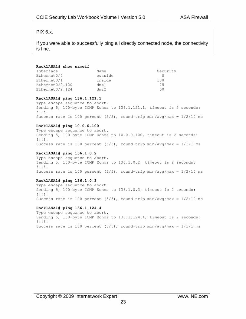
Next we verify nameifs in the ASA unit and try pinging the directly connected subnets. Note that with version 7.x of the code, the ASA unit will accept echo-reply ICMP messages by default, so you don’t have to enable it like you did in
CCIE Security Lab Workbook Volume I Version 5.0 ASA Firewall
Copyright © 2009 Internetwork Expert www.INE.com23
PIX 6.x.
If you were able to successfully ping all directly connected node, the connectivity is fine.
Rack1ASA1# show nameif Interface Name Security Ethernet0/0 outside 0 Ethernet0/1 inside 100 Ethernet0/2.120 dmz1 75 Ethernet0/2.124 dmz2 50
Rack1ASA1# ping 136.1.121.1 Type escape sequence to abort. Sending 5, 100-byte ICMP Echos to 136.1.121.1, timeout is 2 seconds: !!!!! Success rate is 100 percent (5/5), round-trip min/avg/max = 1/2/10 ms
Rack1ASA1# ping 10.0.0.100 Type escape sequence to abort. Sending 5, 100-byte ICMP Echos to 10.0.0.100, timeout is 2 seconds: !!!!! Success rate is 100 percent (5/5), round-trip min/avg/max = 1/1/1 ms
Rack1ASA1# ping 136.1.0.2 Type escape sequence to abort. Sending 5, 100-byte ICMP Echos to 136.1.0.2, timeout is 2 seconds: !!!!! Success rate is 100 percent (5/5), round-trip min/avg/max = 1/2/10 ms
Rack1ASA1# ping 136.1.0.3 Type escape sequence to abort. Sending 5, 100-byte ICMP Echos to 136.1.0.3, timeout is 2 seconds: !!!!! Success rate is 100 percent (5/5), round-trip min/avg/max = 1/2/10 ms
Rack1ASA1# ping 136.1.124.4 Type escape sequence to abort. Sending 5, 100-byte ICMP Echos to 136.1.124.4, timeout is 2 seconds: !!!!! Success rate is 100 percent (5/5), round-trip min/avg/max = 1/1/1 ms

CCIE Security Lab Workbook Volume I Version 5.0 ASA Firewall
Copyright © 2009 Internetwork Expert www.INE.com24
1.2 Configuring RIPv2 • Enable RIPv2 on ASA1 for networks 10.0.0.0/8 and 136.X.0.0/16. • Ensure routing summaries are not generated automatically on the classful
subnets boundaries. • Do not send RIPv2 updates out of any interfaces except to “Inside” and
“DMZ1”. • Configure RIPv2 on R1 using the network 136.X.0.0/16. • Authenticate RIPv2 updates sent/received to/from R1 using the key-string
“CISCO”. • Use the most secure form of authentication.
Configuration
Note
Configuring RIPv2 in the ASA unit includes the following steps (some of those could be omitted, like authenticating protocol updates):
1) (Mandatory). Starting the RIP routing process and defining version 2 (almost no one uses version 1 nowadays). Also, disable auto-summary as the legacy classful protocol feature. This step is identical to the initial configuration of RIPv2 in IOS routers.
2) (Mandatory). Defining the networks where RIP updates will be send and that will be advertised into RIP. You enter the network statements, defining classful networks. RIP process finds all interfaces matching those networks, and starts sending/receiving updates on those interfaces. At the same time, the local subnets matching the network statement will be advertised in RIP updates.
3) (Optional). You define the passive interfaces, to limit the scope of interfaces selected for sending RIP updates. Keep in mind that a passive interface never sends any updates, but still accepts them. You may define ALL interfaces as passive by using the command passive-interface default, and then selectively enable some interfaces using the command no passive-interface X. This is what we’ve done in our scenario.
4) (Optional). Authenticate routing updates is needed. RIPv2 supports two authentication types – plain text (non-secure, default) and MD5 hash. In both cases, you define a key on the interface and configure this interface for proper RIPv2 authentication mode. There could be multiple keys defined on the interface, but only the first one is used to authenticate the incoming and outgoing updates. However, with MD5 mode, other keys are used to accept incoming

CCIE Security Lab Workbook Volume I Version 5.0 ASA Firewall
Copyright © 2009 Internetwork Expert www.INE.com25
updates with a matching key.
While routing has been pre-configured in routers, you still need to know how to authenticate RIPv2 packets in an IOS router. The process is a bit different from the ASA. First, you create a key-chain in global configuration mode, which may contain one or more authentication keys. You then apply the key-chain to an interface, configured for proper RIPv2 authentication mode (MD5 or plain-text). The router will use the first key to authenticate the incoming/outgoing updates. Other keys are used with MD5 authentication mode to accept the matching incoming updates.
ASA1: ! ! RIP process configuration ! router rip network 10.0.0.0 network 136.1.0.0 passive-interface default no passive-interface inside no passive-interface dmz1 version 2 no auto-summary
! ! MD5 Authentication on the Inside interface ! interface Ethernet0/1 rip authentication mode md5 rip authentication key CISCO key_id 1
R1: ! ! Key-chain configuration ! key chain RIP key 1 key-string CISCO ! ! Applying the key-chain and setting the mode ! interface FastEthernet 0/0 ip rip authentication mode md5 ip rip authentication key-chain RIP

CCIE Security Lab Workbook Volume I Version 5.0 ASA Firewall
Copyright © 2009 Internetwork Expert www.INE.com26
Verification
Note
For verification, you first need to check the protocol configuration, using the show ip protocol command in the IOS router. It will reveal you the interfaces configured for RIPv2 authentication along with the respective key-chains.
Rack1R1#show ip protocols Routing Protocol is "rip" Sending updates every 30 seconds Invalid after 180 seconds, hold down 180, flushed after 240 Outgoing update filter list for all interfaces is not set Incoming update filter list for all interfaces is not set Redistributing: rip Default version control: send version 2, receive version 2 Interface Send Recv Triggered RIP Key-chain FastEthernet0/0 2 2 RIP Automatic network summarization is not in effect Maximum path: 4 Routing for Networks: 136.1.0.0 Routing Information Sources: Gateway Distance Last Update Distance: (default is 120)
Note
The next useful command is debug ip rip, which is available in both IOS and ASA platforms. It will show you the contents of RIPv2 updates send on all interfaces enabled for RIP. It will also show you if the incoming packets are authenticated and pass the security checks.
Rack1ASA1# debug rip Rack1ASA1# RIP: sending v2 update to 224.0.0.9 via inside (136.1.121.12) RIP: build update entries 10.0.0.0 255.255.255.0 via 0.0.0.0, metric 1, tag 0 136.1.0.0 255.255.255.0 via 0.0.0.0, metric 1, tag 0 136.1.124.0 255.255.255.0 via 0.0.0.0, metric 1, tag 0 RIP: Update contains 3 routes RIP: Update queued RIP: sending v2 update to 224.0.0.9 via dmz1 (10.0.0.12) RIP: build update entries 136.1.0.0 255.255.255.0 via 0.0.0.0, metric 1, tag 0 136.1.121.0 255.255.255.0 via 0.0.0.0, metric 1, tag 0 136.1.124.0 255.255.255.0 via 0.0.0.0, metric 1, tag 0 RIP: Update contains 3 routes RIP: Update queued

CCIE Security Lab Workbook Volume I Version 5.0 ASA Firewall
Copyright © 2009 Internetwork Expert www.INE.com27
RIP: Update sent via inside rip-len:112 RIP: Update sent via dmz1 rip-len:72
Rack1R1#debug ip rip RIP protocol debugging is on Rack1R1# RIP: sending v2 update to 224.0.0.9 via FastEthernet0/0 (136.1.121.1) RIP: build update entries - suppressing null update RIP: received packet with MD5 authentication RIP: received v2 update from 136.1.121.12 on FastEthernet0/0 10.0.0.0/24 via 0.0.0.0 in 1 hops 136.1.0.0/24 via 0.0.0.0 in 1 hops 136.1.124.0/24 via 0.0.0.0 in 1 hops
Note
Finally, if everything has been authenticated successfully, you should be able to see RIP route in the routing tables.
Rack1R1#show ip route rip 136.1.0.0/24 is subnetted, 3 subnets R 136.1.0.0 [120/1] via 136.1.121.12, 00:00:23, FastEthernet0/0 R 136.1.124.0 [120/1] via 136.1.121.12, 00:00:23, FastEthernet0/0 10.0.0.0/24 is subnetted, 2 subnets R 10.0.0.0 [120/1] via 136.1.121.12, 00:00:23, FastEthernet0/0

CCIE Security Lab Workbook Volume I Version 5.0 ASA Firewall
Copyright © 2009 Internetwork Expert www.INE.com28
1.3 Configuring OSPF • Create OSPF routing process in the ASA firewall using the OSPF process
ID 1 and the OSPF router-ID of 150.X.12.12.2. • Assign interfaces to OSPF areas per the diagram provided. • Ensure the ASA is never elected as DR on both segments. • Authenticate the OSPF adjacency across “DMZ2” interface using
interface-level commands only. Use the password of “CISCO” and most secure form of authentication.
• Configure the less secure form of OSPF authentication on the interface “Outside”. Use only process-level commands for this along with the password of “CISCO”..
Configuration
Note
OSPF is a complicated link-state routing protocol. The ASA firewall supports many OSPF features found in regular IOS routers. For the purpose of the CCIE security exam, you should probably need to know the following OSPF configuration steps:
1) (Mandatory). Enabling OSPF process with a certain process-ID (there could be multiple OSPF process in a single box) and assigning a router-ID, which identifies the box in the OSPF topology. If you do not assign a router-ID the ASA will pick it up for you automatically. However, it is generally a good practice to assign it manually, to ease the troubleshooting.
2) (Mandatory). Configuring the network statements to identify the interfaces where OSPF should establish adjacencies. The syntax is network <subnet> <subnet-mask> and is different from the syntax used in the IOS routers, where you use the wildcard mask. Every interface that has the IP address matching the configured network statement is selected for establishing OSPF adjacencies. In addition to that, the subnets for those interfaces are advertised as OSPF links and become accessible to the other OSPF routers. Note that OSPF configuration does not support the passive-interface statement, but accepts various network scopes.
3) (Optional). Designate some interfaces as passive for OSPF. Unlike RIPv2, however, passive OSPF cannot establish OSPF adjacency and exchange link stats. Thus, a passive interface is advertised into OSPF but not used for any routing information exchange.
4) (Optional). Configure the ASA unit as designated or non-designated router on

CCIE Security Lab Workbook Volume I Version 5.0 ASA Firewall
Copyright © 2009 Internetwork Expert www.INE.com29
the active OSPF interfaces. Designated OSPF routers (DRs) are used on shared interfaces, like Ethernet, to centralize routing information exchange. Commonly, a DR is the most powerful and stable router on the segment. By default, the first router to boot up and initialize is elected as DR. If there are many routers conquering for the DR role, the one with highest OSPF interface priority is selected as the DR. If the priorities match, the router with the highest Router-ID is elected as the DR. If you set the OSPF priority to zero on a given interface, the ASA will not even attempt to become a DR. Note that the router might be a DR on one segment and non-DR on another. Manipulating priorities might be needed, as the default value is one, which might result in non-deterministic DR elections.
And the most important thing of OSPF configuration from the security standpoint is protocol authentication. OSPF authenticates all OSPF packets (authentication is a part of OSPF header, and OSPF has the IP protocol number of 89) supports three types of authentication: null (empty), plain-text (clear text password) and secure MD5 hash over the packet contents. Note that OSPF authenticates the packet exchange on a given segment connection. You may define various authentication types on different interfaces. First, look at the authentication types:
1) NULL – explicitly states that the packet is not authenticated. 2) Plain-text – carries a password in the header. Only one password is allowed. 3) MD5-hash – carries a key ID along with the corresponding hash value in the header. There could be different key IDs, and the receiving router selects the appropriate local key based on the key ID in the header. You can configure multiple keys on a single interface, and the router will send packets authenticated with every active key.
You can enable OSPF authentication on the interface using the commands ospf authentication for the ASA or ip ospf authentication for the IOS routers. To set the MD5 keys, use the commands ospf message-digest-key and ip ospf message-digest-key respectively. Using this command you set the mode and the respective keys on the particular interface. Alternatively, you can use the process-level command area X authentication [message-digest] to enable authentication on all interfaces that are members of the particular area. You still need to configure the keys at interface level however.

CCIE Security Lab Workbook Volume I Version 5.0 ASA Firewall
Copyright © 2009 Internetwork Expert www.INE.com30
ASA1: ! ! OSPF routing process ! router ospf 1 network 136.1.0.0 255.255.255.0 area 0 network 136.1.124.0 255.255.255.0 area 1 router-id 150.1.12.12 area 0 authentication ! ! Authentication for area 1 is configured solely on interface ! interface Ethernet0/2.124 ospf message-digest-key 1 md5 CISCO ospf authentication message-digest ospf priority 0 ! ! Only the auth key is configured at interface level ! interface Ethernet0/0 ospf authentication-key CISCO ospf priority 0
R2: router ospf 1 area 0 authentication
! interface FastEthernet 0/0 ip ospf authentication-key CISCO
R3: router ospf 1 area 0 authentication
! interface FastEthernet 0/0 ip ospf authentication-key CISCO
R4: interface FastEthernet 0/0 ip ospf authentication message-digest ip ospf message-digest-key 1 md5 CISCO
Verification
Note
The verification is simple. First, make sure you haven’t lost your OSPF neighbors after the authentication. If you lose adjacencies and cannot fix that, better disable the authentication and move on.
Rack1ASA1# show ospf neighbor

CCIE Security Lab Workbook Volume I Version 5.0 ASA Firewall
Copyright © 2009 Internetwork Expert www.INE.com31
Neighbor ID Pri State Dead Time Address Interface 150.1.2.2 1 FULL/BDR 0:00:38 136.1.0.2 outside 150.1.3.3 1 FULL/DR 0:00:35 136.1.0.3 outside 150.1.4.4 1 FULL/DR 0:00:39 136.1.124.4 dmz2
Note
If you need to check the detailed authentication settings, to see if they match on both sides, use the interface-level ospf commands: (show ospf interface or show ip ospf interface in IOS). Here you can see the adjacent neighbors and the authentication key settings. For OSPF, make sure they key indexes for MD5 match, not just the key strings.
Rack1ASA1# show ospf interface
outside is up, line protocol is up Internet Address 136.1.0.12 mask 255.255.255.0, Area 0 Process ID 1, Router ID 150.1.12.12, Network Type BROADCAST, Cost: 10 Transmit Delay is 1 sec, State DROTHER, Priority 0 Designated Router (ID) 150.1.3.3, Interface address 136.1.0.3 Backup Designated router (ID) 150.1.2.2, Interface address 136.1.0.2 Flush timer for old DR LSA due in 0:00:42 Timer intervals configured, Hello 10, Dead 40, Wait 40, Retransmit 5 Hello due in 0:00:05 Index 1/1, flood queue length 0 Next 0x0(0)/0x0(0) Last flood scan length is 0, maximum is 3 Last flood scan time is 0 msec, maximum is 0 msec Neighbor Count is 2, Adjacent neighbor count is 2 Adjacent with neighbor 150.1.2.2 (Backup Designated Router) Adjacent with neighbor 150.1.3.3 (Designated Router) Suppress hello for 0 neighbor(s) Simple password authentication enabled dmz2 is up, line protocol is up Internet Address 136.1.124.12 mask 255.255.255.0, Area 1 Process ID 1, Router ID 150.1.12.12, Network Type BROADCAST, Cost: 10 Transmit Delay is 1 sec, State DROTHER, Priority 0 Designated Router (ID) 150.1.4.4, Interface address 136.1.124.4 No backup designated router on this network Flush timer for old DR LSA due in 0:00:31 Timer intervals configured, Hello 10, Dead 40, Wait 40, Retransmit 5 Hello due in 0:00:01 Index 1/2, flood queue length 0 Next 0x0(0)/0x0(0) Last flood scan length is 1, maximum is 3 Last flood scan time is 0 msec, maximum is 0 msec Neighbor Count is 1, Adjacent neighbor count is 1 Adjacent with neighbor 150.1.4.4 (Designated Router) Suppress hello for 0 neighbor(s) Message digest authentication enabled

CCIE Security Lab Workbook Volume I Version 5.0 ASA Firewall
Copyright © 2009 Internetwork Expert www.INE.com32
1.4 EIGRP • Disable OSPF on the connection to R4 and configure EIGRP AS 1instead. • Authenticate the EIGRP adjacency using the password value of CISCO.
Configuration
Note
EIGRP is a recent addition to the ASA code. This routing protocol is Cisco’s proprietary and you may need it in purely Cisco environment. Per itself EIGRP is a sophisticated distributed (diffused) computations-based and scalable protocol. However, EIGRP configuration is relatively simple and requires just a few steps.
1) Enable EIGRP routing process on the firewall. You will need to know the Autonomous System number used by neighboring routers, to enter the command router eigrp <AS#>. If the AS numbers mismatch, the routers will not form an adjacency.
2) Activate EIGRP on selected interfaces, using the command network <IP> <Mask>. This is similar to OSPF configuration, though this time you don’t specify the area number. EIGRP will start sending HELLO packets out of all matching interfaces as well as advertising the matching subnets to its neighbors. Disable automatic route summarization (not needed in modern networks) using the command no auto-summary.
3) Authenticate EIGRP adjacency on the interfaces where this is required. EIGRP supports only secure MD5-hash based authentication. You may enable it at the interface level using the commands:
authentication mode eigrp X md5 authentication key eigrp X <KEY> key-id N
4) Configure the opposing IOS router for EIGRP authentication as well. The IOS syntax is a bit different and requires you creating a key chain first:
key chain <KEY-CHAIN> key N key-string <KEY>
interface FastEthernet X/Y ip authentication mode eigrp X md5 ip authentication key eigrp X <KEY-CHAIN>

CCIE Security Lab Workbook Volume I Version 5.0 ASA Firewall
Copyright © 2009 Internetwork Expert www.INE.com33
Ensure the key identifiers match at both sides for authentication to succeed.
ASA1: router ospf 1 no network 136.1.124.0 255.255.255.0 ! router eigrp 1 no auto-summary network 136.1.124.0 255.255.255.0 ! interface Ethernet 0/2.124 authentication key eigrp 1 CISCO key-id 1 authentication mode eigrp 1 md5
R4: router eigrp 1 network 136.1.124.0 0.0.0.255 ! key chain EIGRP key 1 key-string CISCO ! interface FastEthernet 0/0 ip authentication mode eigr 1 md5 ip authentication key eigrp 1 EIGRP
Verification
Note
Start your verifications by checking EIGRP adjacency state. Note that SRTT value should be reasonably small (this is the average time to reach the neighbor over the segment) and the “Q” field (outstanding queries) should be zero in a stable network. If the authentication keys mismatch, the adjacency will never come up.
Rack1ASA1# show eigrp neighbors EIGRP-IPv4 neighbors for process 1 H Address Interface Hold Uptime SRTT RTO Q Seq (sec) (ms) Cnt Num 0 136.1.124.4 Et0/2.124 12 00:29:12 1 200 0 9
Note
CCIE Security Lab Workbook Volume I Version 5.0 ASA Firewall
Copyright © 2009 Internetwork Expert www.INE.com34
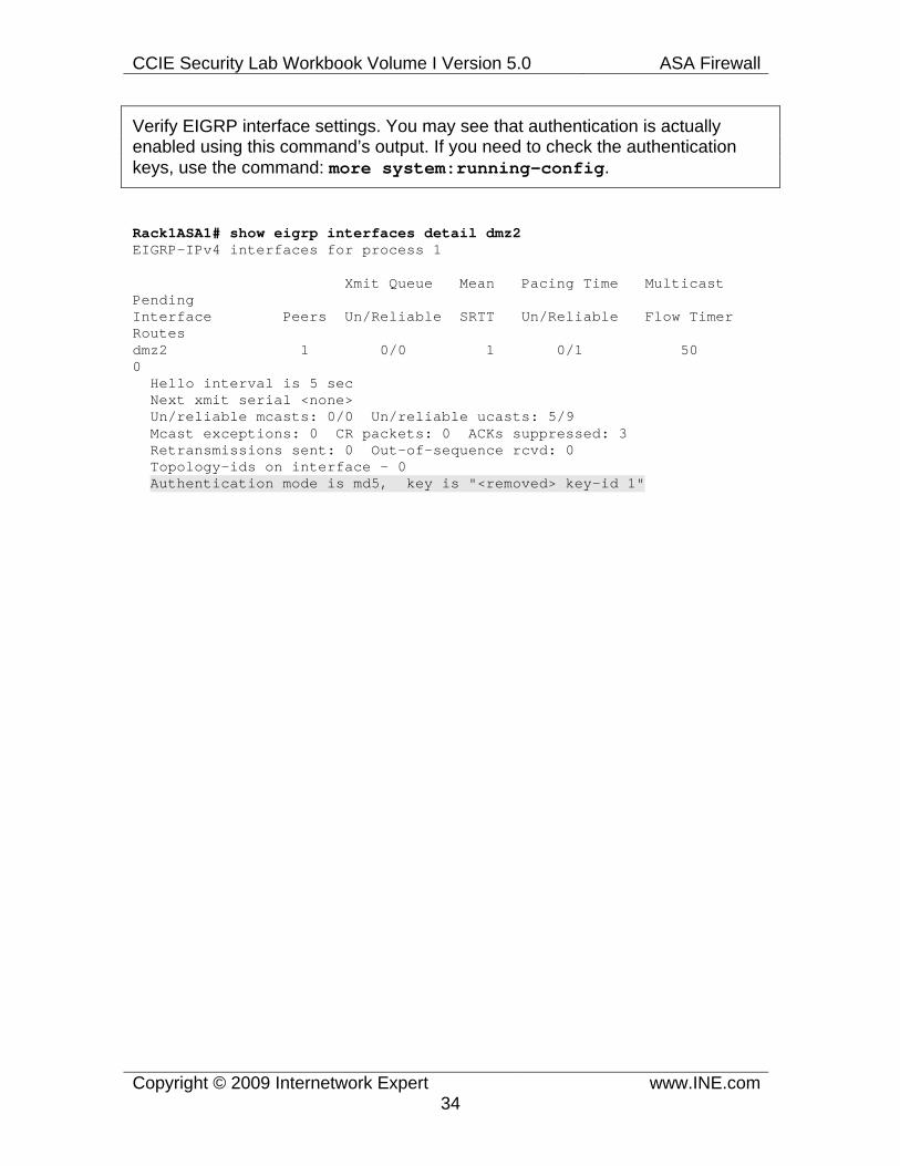
Verify EIGRP interface settings. You may see that authentication is actually enabled using this command’s output. If you need to check the authentication keys, use the command: more system:running-config.
Rack1ASA1# show eigrp interfaces detail dmz2 EIGRP-IPv4 interfaces for process 1
Xmit Queue Mean Pacing Time Multicast Pending Interface Peers Un/Reliable SRTT Un/Reliable Flow Timer Routes dmz2 1 0/0 1 0/1 50 0 Hello interval is 5 sec Next xmit serial <none> Un/reliable mcasts: 0/0 Un/reliable ucasts: 5/9 Mcast exceptions: 0 CR packets: 0 ACKs suppressed: 3 Retransmissions sent: 0 Out-of-sequence rcvd: 0 Topology-ids on interface - 0 Authentication mode is md5, key is "<removed> key-id 1"

CCIE Security Lab Workbook Volume I Version 5.0 ASA Firewall
Copyright © 2009 Internetwork Expert www.INE.com35
1.5 Advanced Routing • Implement a reliable default route towards R2 in the firewall. Track R2’s
Loopback0 reachability for that. • Use R3 as the backup default gateway. • Redistribute RIP and EIGRP routes into OSPF. • Originate the default route into RIPv2 and EIGRP.
Configuration
Note
The CCIE Security lab most likely will not require you to perform advanced routing protocols tuning. However, some basic routing features should be known by every candidate. This task requires you to redistribute between the routing protocols. That means you should inject other protocols routing information into another routing protocol. This is needed to obtain full reachability between the routing domains connected by the firewall.
The main command you need to know is the one entered within the routing protocol context: redistribute <Source-Protocol> metric <Seed-Metric>. For example:
router rip redistribute ospf 1 metric 1 redistribute static
Pay attention to the <Seed-Metric>. This metric is needed practically all the time, if only you are not redistributing “connected” or “static” routes. It specifies the initial metric to be assigned to the redistributed routes. The metric is in the units understood by the “target” routing protocol. Also, note that using the “redistribute connected” is another way of advertising the locally connected interfaces into a routing protocol.
Instead of redistributing routing information into a protocol, you may simply originate a default route into the protocol. To do that with RIPv2 or OSPF, use the command default-information originate. This command will always advertise a default route into RIPv2; however it will advertise the default route into OSPF if this route exists in the local routing table. If you want the route to be always advertised into OSPF, use the command default-information originate always. As for EIGRP, there is no special command to originate a default route there. However, you may use the command redistribute static to advertise the local static default route into EIGRP as well.

CCIE Security Lab Workbook Volume I Version 5.0 ASA Firewall
Copyright © 2009 Internetwork Expert www.INE.com36
Another important routing feature is static reliable routing. It allows you creating a special “tracker” that pings a destination and reports the reachability state. The tracker could be associated with the static route, making the route active only when the tracker is “up”. This might be very helpful with static routes, as you can track the actual reachability of the next hop. For example, you may configure a primary route via a route, and track the next-hop reachability. If the tracker would fail, the secondary static route will preempt the primary one, and the traffic will flow via the backup path.
You configure a tracker in two steps:
1) Creating a new SLA monitor operation (SLA = Service Level Agreement) which constantly pings a destination and reports the reachability. You may tune the following two parameters: timeout (the time to expire every probe, in ms) and frequency (how often to send the probes). The more often you ping, the faster you will detect the loss of connectivity. However, this might cause frequent flaps in case of unstable network.
2) Creating a tracking object using the track command and attach it to a static route. The tracking object will reference the SLA operation number, and the static route will reference the tracking object number.
The backup static route should point to the same destination by have numerically higher distance, signaling its lower preference. E.g.
route outside 0 0 <IP> <Distance>. The default <Distance> value is “1” and it is assigned to the primary static route.
ASA1: sla monitor 1 type echo protocol ipIcmpEcho 150.1.2.2 interface outside timeout 1000
frequency 1 sla monitor schedule 1 life forever start-time now ! track 1 rtr 1 reachability ! route outside 0 0 136.1.0.2 track 1 route outside 0 0 136.1.0.3 100 ! router ospf 1 redistribute rip subnets redistribute eigrp 1 subnets ! router rip default-information originate !

CCIE Security Lab Workbook Volume I Version 5.0 ASA Firewall
Copyright © 2009 Internetwork Expert www.INE.com37
router eigrp 1 redistribute static
Verification
Note
First, make sure that R2 learns redistributed routes via OSPF. Notice that external OSPF routes are marked as “O E2” or “O E1”.
Rack1R2#show ip route ospf 136.1.0.0/24 is subnetted, 4 subnets O 136.1.100.0 [110/2] via 136.1.0.3, 01:47:47, FastEthernet0/0 O E2 136.1.121.0 [110/20] via 136.1.0.12, 00:09:07, FastEthernet0/0 O IA 136.1.124.0 [110/11] via 136.1.0.12, 00:09:07, FastEthernet0/0 10.0.0.0/24 is subnetted, 1 subnets O E2 10.0.0.0 [110/20] via 136.1.0.12, 00:09:07, FastEthernet0/0 150.1.0.0/16 is variably subnetted, 3 subnets, 2 masks O E2 150.1.1.0/24 [110/20] via 136.1.0.12, 00:09:07, FastEthernet0/0 O IA 150.1.4.4/32 [110/12] via 136.1.0.12, 00:09:07, FastEthernet0/0 O 150.1.3.3/32 [110/2] via 136.1.0.3, 01:47:47, FastEthernet0/0
Note
Now test the reliable static default route. First, check the tracking object state, and check the next-hop for the default route in the ASA routing table. If the object is up, the next-hop is R2.
Rack1ASA1# show track Track 1 Response Time Reporter 1 reachability Reachability is Up 3 changes, last change 00:05:32 Latest operation return code: OK Latest RTT (millisecs) 1 Tracked by: STATIC-IP-ROUTING 0
Rack1ASA1# show route
Codes: C - connected, S - static, I - IGRP, R - RIP, M - mobile, B - BGP D - EIGRP, EX - EIGRP external, O - OSPF, IA - OSPF inter area N1 - OSPF NSSA external type 1, N2 - OSPF NSSA external type 2 E1 - OSPF external type 1, E2 - OSPF external type 2, E - EGP i - IS-IS, L1 - IS-IS level-1, L2 - IS-IS level-2, ia - IS-IS inter area * - candidate default, U - per-user static route, o - ODR P - periodic downloaded static route
Gateway of last resort is 136.1.0.2 to network 0.0.0.0

CCIE Security Lab Workbook Volume I Version 5.0 ASA Firewall
Copyright © 2009 Internetwork Expert www.INE.com38
C 136.1.0.0 255.255.255.0 is directly connected, outside O 136.1.100.0 255.255.255.0 [110/11] via 136.1.0.3, 0:00:57, outside C 136.1.121.0 255.255.255.0 is directly connected, inside C 136.1.124.0 255.255.255.0 is directly connected, dmz2 C 10.0.0.0 255.255.255.0 is directly connected, dmz1 R 150.1.1.0 255.255.255.0 [120/1] via 136.1.121.1, 0:00:13, inside O 150.1.3.3 255.255.255.255 [110/11] via 136.1.0.3, 0:00:57, outside O 150.1.4.4 255.255.255.255 [110/11] via 136.1.124.4, 0:00:57, dmz2 S* 0.0.0.0 0.0.0.0 [1/0] via 136.1.0.2, outside Rack1ASA1#
Note
Now shut down R2’s Loopback0 interface, and see that the tracking object goes down. At the same time, the default route in the ASA now points to R3:
Rack1R2#conf t Enter configuration commands, one per line. End with CNTL/Z. Rack1R2(config)#interface loopback 0 Rack1R2(config-if)#shutdown Rack1R2(config-if)#
Rack1ASA1# show track Track 1 Response Time Reporter 1 reachability Reachability is Down 4 changes, last change 00:00:12 Latest operation return code: Timeout Tracked by: STATIC-IP-ROUTING 0
Rack1ASA1# show route
Codes: C - connected, S - static, I - IGRP, R - RIP, M - mobile, B - BGP D - EIGRP, EX - EIGRP external, O - OSPF, IA - OSPF inter area N1 - OSPF NSSA external type 1, N2 - OSPF NSSA external type 2 E1 - OSPF external type 1, E2 - OSPF external type 2, E - EGP i - IS-IS, L1 - IS-IS level-1, L2 - IS-IS level-2, ia - IS-IS inter area * - candidate default, U - per-user static route, o - ODR P - periodic downloaded static route
Gateway of last resort is 136.1.0.3 to network 0.0.0.0
C 136.1.0.0 255.255.255.0 is directly connected, outside O 136.1.100.0 255.255.255.0 [110/11] via 136.1.0.3, 0:01:34, outside C 136.1.121.0 255.255.255.0 is directly connected, inside C 136.1.124.0 255.255.255.0 is directly connected, dmz2 C 10.0.0.0 255.255.255.0 is directly connected, dmz1 R 150.1.1.0 255.255.255.0 [120/1] via 136.1.121.1, 0:00:23, inside O 150.1.3.3 255.255.255.255 [110/11] via 136.1.0.3, 0:01:34, outside O 150.1.4.4 255.255.255.255 [110/11] via 136.1.124.4, 0:01:34, dmz2

CCIE Security Lab Workbook Volume I Version 5.0 ASA Firewall
Copyright © 2009 Internetwork Expert www.INE.com39
S* 0.0.0.0 0.0.0.0 [100/0] via 136.1.0.3, outside
Note
Finally check the routing table of R1 and R4 to see that they actually receive the default route from the ASA firewall:
Rack1R1#show ip route rip 136.1.0.0/24 is subnetted, 3 subnets R 136.1.0.0 [120/1] via 136.1.121.12, 00:00:05, FastEthernet0/0 R 136.1.124.0 [120/1] via 136.1.121.12, 00:00:05, FastEthernet0/0 10.0.0.0/24 is subnetted, 1 subnets R 10.0.0.0 [120/1] via 136.1.121.12, 00:00:05, FastEthernet0/0 R* 0.0.0.0/0 [120/1] via 136.1.121.12, 00:00:05, FastEthernet0/0 Rack1R1#
Rack1R4#show ip route eigrp D*EX 0.0.0.0/0 [170/28416] via 136.1.124.12, 00:01:50, FastEthernet0/0

CCIE Security Lab Workbook Volume I Version 5.0 ASA Firewall
Copyright © 2009 Internetwork Expert www.INE.com40
1.6 IP Access-Lists • Implement the access policy outlined below. • Permit the following incoming traffic:
o Incoming ping requests and replied to pings from the inside. o FTP/HTTP/NTP traffic to AAA/CA server o Returning traffic for the UNIX-style traceroute command.
• Permit the following types of outgoing traffic:
o Pings and replies to the pings sent from the outside. o Outgoing packets for the UNIX-style traceroute command. o Outgoing telnet, FTP, HTTP traffic
• . Use just two access-list named OUTSIDE_IN and OUTSIDE_OUT applied ingress and egress to the “Outside” interface. .
Configuration
Note
Access-lists are your core instrument to implement traffic filtering in the ASA firewalls. By default, the firewall unit permits sessions to be initiated from the higher security level interface to the lower security level interfaces. This rule only applies to the traffic inspected by the firewall, by dynamically opening holes in the filtering logic for returning packets.
Using the access-lists allows you to do the following:
1) Permitting access from the lower security level interfaces to higher security level interfaces. 2) Permitting return traffic for sessions that are not inspected by the ASA firewall (e.g. for ICMP, which is not inspected by default, or for the traceroute command). 3) Filtering routing updates for OSPF and RIP routing processes (on a rare occasion).
For (1) and (2) you need to use the extended access-list (the default type) which allows matching on source and destination IP and TCP/UDP/ICMP protocols information. For (3) you should use the standard access-lists that only match on the source subnet.
Extended access-list could be applied either inbound or outbound to an interface. Note that if you apply an access-list in the direction that matches traffic flow from

CCIE Security Lab Workbook Volume I Version 5.0 ASA Firewall
Copyright © 2009 Internetwork Expert www.INE.com41
higher to lower security interface (e.g. ingress on the inside or egress on the outside) you may prevent the automatically inspected traffic to flow across the firewall. This is because every access-list has an implicit deny all statement in the end. Most of the times you just need to apply the access-list ingress on the lower security level interfaces to permit inbound traffic, and let the stateful inspection engine do the rest of the work for you. In our example we use both outgoing and incoming access-list for the sake of completeness.
To properly craft an access-list you need to know your protocol mechanics in depth. For example you should know the default service ports (e.g. for FTP, SMTP, WWW) and know how complicated commands like traceroute works. Many protocols, like NTP or WWW use a single port number, which you could learn by browsing the command-line help when configuring the access-list and pressing the “?” key. Note that IOS routers usually give you more information on port numbers in this manner than the ASA firewall does.
In our task, we permit inbound NTP, FTP and WWW sessions. Note that for FTP we only open port 21. The inspection engine will automatically open holes for the passive FTP connections if needed. Note that we enable inbound ICMP echo-replies, to allow the inside hosts to ping the hosts outside. By default they cannot do this, as ICMP is not inspected. Alternatively, you may enable ICMP inspection, as we will see later in the MPF tasks.
Note the amount of work needed to permit the traceroute command (UNIX-style) which uses UDP probes. You need to allow the returning ICMP unreachables along with the outgoing UDP packets for the default traceroute port range. Note that if you don’t apply an outgoing ACL, there is no need to permit the outgoing UDP packets, as those are inspected by default.
ASA1: ! ! Ingress ACL: Allow accessing the server ! access-list OUTSIDE_IN extended permit tcp any host 10.0.0.100 eq www access-list OUTSIDE_IN extended permit tcp any host 10.0.0.100 eq ftp access-list OUTSIDE_IN extended permit udp any host 10.0.0.100 eq ntp
! ! Allow pings across the firewall ! access-list OUTSIDE_IN extended permit icmp any any echo access-list OUTSIDE_IN extended permit icmp any any echo-reply
! ! Allow traceroute return packets ! access-list OUTSIDE_IN extended permit icmp any any time-exceeded access-list OUTSIDE_IN extended permit icmp any any unreachable

CCIE Security Lab Workbook Volume I Version 5.0 ASA Firewall
Copyright © 2009 Internetwork Expert www.INE.com42
! ! Egress ACL: permit ping packets ! access-list OUTSIDE_OUT extended permit icmp any any echo access-list OUTSIDE_OUT extended permit icmp any any echo-reply
! ! Permit outgoing traceroute packets ! access-list OUTSIDE_OUT extended permit udp any any range 33434 33464 access-list OUTSIDE_OUT extended permit tcp any any eq ftp
! ! Permit telnet and HTTP access ! access-list OUTSIDE_OUT extended permit tcp any any eq telnet access-list OUTSIDE_OUT extended permit tcp any any eq www
! ! Apply the access-lists ! access-group OUTSIDE_IN in interface outside access-group OUTSIDE_OUT out interface outside
Verification
Note
Verification consists of simulating the required traffic types and seeing if it passes across the firewall. Note that you can use debug icmp trace to see if the ICMP packets get across the firewall, but we don’t use the command here.
Rack1R2#ping 10.0.0.100
Type escape sequence to abort. Sending 5, 100-byte ICMP Echos to 10.0.0.100, timeout is 2 seconds: !!!!! Success rate is 100 percent (5/5), round-trip min/avg/max = 1/3/8 ms
Rack1R2#ping 136.1.121.1
Type escape sequence to abort. Sending 5, 100-byte ICMP Echos to 136.1.121.1, timeout is 2 seconds: !!!!! Success rate is 100 percent (5/5), round-trip min/avg/max = 1/3/4 ms
Note
For HTTP, simulate a GET request by connection on port 80 using the telnet command. Terminate the connection by pressing Ctrl-Shift-6-x and then typing

CCIE Security Lab Workbook Volume I Version 5.0 ASA Firewall
Copyright © 2009 Internetwork Expert www.INE.com43
disconnect 1. You can also telnet on port 21 to see if the FTP banner appears.
Rack1R2#telnet 10.0.0.100 80 Trying 10.0.0.100, 80 ... Open get / http/1.1
HTTP/1.1 400 Bad Request Server: Microsoft-IIS/5.0 Date: Sat, 06 Jan 2007 11:22:27 GMT Content-Type: text/html Content-Length: 87
<html><head><title>Error</title></head><body>The parameter is incorrect. </body></html> [Connection to 10.0.0.100 closed by foreign host]
Rack1R2#telnet 10.0.0.100 21 Trying 10.0.0.100, 21 ... Open 220 IESERVER1 Microsoft FTP Service (Version 5.0).
Rack1R2#disc 1 Closing connection to 10.0.0.100 [confirm]
Note
Try connecting to the AAA/CA server on any port not opened in the ACLs and see that the connection times out (the firewall simply drops the packets). Ensure that telnet to R2 works still.
Rack1R2#telnet 10.0.0.100 25 Trying 10.0.0.100, 25 ... % Connection timed out; remote host not responding
Rack1R1#telnet 136.1.122.2 Trying 136.1.122.2 ... Open
User Access Verification
Password: cisco Rack1R2>
Note
Repeat the verifications from R1:
Rack1R1#ping 136.1.122.2

CCIE Security Lab Workbook Volume I Version 5.0 ASA Firewall
Copyright © 2009 Internetwork Expert www.INE.com44
Type escape sequence to abort. Sending 5, 100-byte ICMP Echos to 136.1.122.2, timeout is 2 seconds: !!!!! Success rate is 100 percent (5/5), round-trip min/avg/max = 1/2/4 ms
Rack1R1#ping 10.0.0.100
Type escape sequence to abort. Sending 5, 100-byte ICMP Echos to 10.0.0.100, timeout is 2 seconds: ..... Success rate is 0 percent (0/5)
Rack1R1#telnet 10.0.0.100 80 Trying 10.0.0.100, 80 ... Open get / http/1.1.
HTTP/1.1 400 Bad Request Server: Microsoft-IIS/5.0 Date: Sat, 06 Jan 2007 11:25:59 GMT Content-Type: text/html Content-Length: 87
<html><head><title>Error</title></head><body>The parameter is incorrect. </body></html> [Connection to 10.0.0.100 closed by foreign host]
Note
Now test the traceroute command from R1 and see that it works:
Rack1R1#traceroute 136.1.122.2
Type escape sequence to abort. Tracing the route to 136.1.122.2
1 136.1.122.2 0 msec * 0 msec
Note
Finally, check the access-list counters in the ASA firewall (look for “hitcnt”)
Rack1ASA1# show access-list access-list cached ACL log flows: total 0, denied 0 (deny-flow-max 4096) alert-interval 300 access-list OUTSIDE_IN; 7 elements access-list OUTSIDE_IN line 1 extended permit tcp any host 10.0.0.100 eq www (hitcnt=1) 0x59f08b76 access-list OUTSIDE_IN line 2 extended permit tcp any host 10.0.0.100 eq ftp (hitcnt=1) 0x8997bedf

CCIE Security Lab Workbook Volume I Version 5.0 ASA Firewall
Copyright © 2009 Internetwork Expert www.INE.com45
access-list OUTSIDE_IN line 3 extended permit udp any host 10.0.0.100 eq ntp (hitcnt=0) 0x8189f120 access-list OUTSIDE_IN line 4 extended permit icmp any any echo-reply (hitcnt=10) 0xc857b49e access-list OUTSIDE_IN line 5 extended permit icmp any any time-exceeded (hitcnt=0) 0xc3b80d access-list OUTSIDE_IN line 6 extended permit icmp any any unreachable (hitcnt=5) 0xec6c9a23 access-list OUTSIDE_IN line 7 extended permit icmp any any echo (hitcnt=70) 0x869bdf05 access-list OUTSIDE_OUT; 6 elements access-list OUTSIDE_OUT line 1 extended permit icmp any any echo (hitcnt=10) 0x4006da3f access-list OUTSIDE_OUT line 2 extended permit udp any any range 33434 33464 (hitcnt=7) 0xde5f72ee access-list OUTSIDE_OUT line 3 extended permit tcp any any eq ftp (hitcnt=0) 0xf47b788 access-list OUTSIDE_OUT line 4 extended permit tcp any any eq telnet (hitcnt=3) 0x2be5bbfe access-list OUTSIDE_OUT line 5 extended permit tcp any any eq www (hitcnt=0) 0x8a4b160e access-list OUTSIDE_OUT line 6 extended permit icmp any any echo-reply (hitcnt=15) 0xd6d9967

CCIE Security Lab Workbook Volume I Version 5.0 ASA Firewall
Copyright © 2009 Internetwork Expert www.INE.com46
1.7 Object Groups • Create the following object groups:
o SERVERS containing the host 10.0.0.100. o ROUTERS containing network 136.X.121.0/24 to it. o COMMON_ICMP containing the ICMP types corresponding to the
ping and UNIX-style traceroute commands. o TRC_PORTS containing the range of UDP ports 33434-33464. o SERVER_PORTS containing TCP ports for HTTP and FTP. o ROUTER_PORTS and add TCP ports corresponding to
Telnet/SSH in addition to port 7001 to the group.
• Reduce the size of the previously created access-lists using the object groups just created.
Configuration
Note
Objects groups allow simplifying large access-list configuration. You can group objects of similar nature (e.g. a group networks and host, a collection of TCP ports, a bunch of ICMP message types) and then reference them in access-lists. Thus, instead of working with addresses and port number you can work with higher level objects that reflect the logical structure of your network. For example you may have object groups PUBLIC_HOSTING listing the publically accessible servers and MANAGEMENT_SEGMENT listing the management stations along with PUBLIC_PORTS group, listing the FTP, WWW, HTTPS ports. By building your access-list out of objects groups, you make them more readable and manageable, as you don’t need to add new ACL entries for every new public server.
Object groups are very intuitive to use, and most time you will not face any problems creating and configuring access-list using the object groups. However, remember that object-groups are good for use with interface access-list, not the access-lists used to building VPN proxy identities, such as split ACLs.

CCIE Security Lab Workbook Volume I Version 5.0 ASA Firewall
Copyright © 2009 Internetwork Expert www.INE.com47
ASA1: ! ! Define object groups ! object-group network ROUTERS network-object 136.1.121.0 255.255.255.0 ! object-group network SERVERS network-object host 10.0.0.100 ! object-group icmp-type COMMON_ICMP icmp-object echo icmp-object echo-reply icmp-object time-exceeded icmp-object unreachable ! object-group service TRC_PORTS udp port-object range 33434 33464 ! object-group service SERVER_PORTS tcp port-object eq www port-object eq ftp
! object-group service ROUTER_PORTS tcp port-object eq telnet port-object eq ssh
port-object eq 7001 ! clear configure access-list OUTSIDE_IN
! ! Define access-lists ! access-list OUTSIDE_IN permit icmp any any obj COMMON_ICMP access-list OUTSIDE_IN permit udp any any obj TRC_PORTS access-list OUTSIDE_IN permit tcp any obj SERVERS obj SERVER_PORTS access-list OUTSIDE_IN permit tcp any obj ROUTERS obj ROUTER_PORTS ! access-list OUTSIDE_OUT permit icmp any any obj COMMON_ICMP access-list OUTSIDE_OUT permit udp any any obj TRC_PORTS access-list OUTSIDE_IN permit tcp any any obj SERVER_PORTS access-list OUTSIDE_IN permit tcp any any obj ROUTER_PORTS
! ! Apply the access-lists ! access-group OUTSIDE_IN in interface outside access-group OUTSIDE_OUT out interface outside

CCIE Security Lab Workbook Volume I Version 5.0 ASA Firewall
Copyright © 2009 Internetwork Expert www.INE.com48
Verification
Note
Use the same verifications that you have done in the previous task. Only the output of the show access-list command has changed, reflecting the object groups. It now displays the object group and all the access-list entries resulting from the application of the object groups.
Rack1ASA1# show access-list access-list cached ACL log flows: total 0, denied 0 (deny-flow-max 4096) alert-interval 300 access-list OUTSIDE_IN; 15 elements access-list OUTSIDE_IN line 1 extended permit icmp any any object-group COMMON_ICMP 0x8ced5a access-list OUTSIDE_IN line 1 extended permit icmp any any echo (hitcnt=10) 0x869bdf05 access-list OUTSIDE_IN line 1 extended permit icmp any any echo-reply (hitcnt=5) 0xc857b49e access-list OUTSIDE_IN line 1 extended permit icmp any any time-exceeded (hitcnt=0) 0xc3b80d access-list OUTSIDE_IN line 1 extended permit icmp any any unreachable (hitcnt=2) 0xec6c9a23 access-list OUTSIDE_IN line 2 extended permit udp any any object-group TRC_PORTS 0x2a19bcff access-list OUTSIDE_IN line 2 extended permit udp any any range 33434 33464 (hitcnt=3) 0x61e01ad <snip>

CCIE Security Lab Workbook Volume I Version 5.0 ASA Firewall
Copyright © 2009 Internetwork Expert www.INE.com49
1.8 Administrative Access • Permit telnet access to the ASA unit from the inside subnet
(136.X.121.0/24). • Permit ssh access to the ASA unit from the outside subnet
(136.X.122.0/24). • Permit users to access the ASDM feature from host 10.0.0.100.
Configuration
Note
You can access the ASA firewall unit remotely using three main access paths: SSH (secure shell), telnet (unencrypted connection) and accessing ASDM via HTTPs (the firewall does not support unsecure HTTP access to the ASDM).
In order to enable any encrypted access via SSH or HTTPs, you need to create a local RSA key-pair, used for HTTPs certificate generation and SSH identity. Before you can generate the key-pair, make sure you have domain-name defined for the firewall, as this is needed to properly label the key-pair and create hostnames for identification. After this, SSH server is enabled automatically.
Use the command ssh <subnet> <mask> <interface> to allow remote subnets to connect via SSH. By default no one is allowed to access the unit via SSH. Don’t forget to define the passwd command, as this will be the password used for SSH authentication (along with the default username of pix). You can also enable local authentication for SSH, using custom names, but this requires enabling local AAA and is covered in a separate task.
The telnet access is configured using the similar telnet <subnet> <mask> <interface> command, but has some restrictions. You can only access the interface with the security-level of 100 using telnet, even if you enable it on the lower-security level interface. If you want to access the non-secure interfaces, make sure telnet traffic is encrypted by an IPsec tunnel, terminating on the mentioned interface. Most of the times, however, you just use SSH.
As for ASDM, you access it via HTTPs. For this to work, ASDM image should be loaded into the flash memory of the firewall, and http server must be enabled. After that, you use the command http <subnet> <mask> <interface> to allow access via HTTPs. The default password to access ASDM is the enable secret defined in the unit.
Note that in any case you don’t have to modify the access-lists applied to any
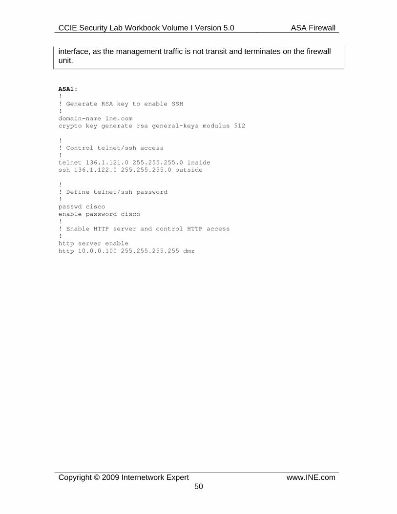
CCIE Security Lab Workbook Volume I Version 5.0 ASA Firewall
Copyright © 2009 Internetwork Expert www.INE.com50
interface, as the management traffic is not transit and terminates on the firewall unit.
ASA1: ! ! Generate RSA key to enable SSH ! domain-name ine.com crypto key generate rsa general-keys modulus 512
! ! Control telnet/ssh access ! telnet 136.1.121.0 255.255.255.0 inside ssh 136.1.122.0 255.255.255.0 outside
! ! Define telnet/ssh password ! passwd cisco enable password cisco ! ! Enable HTTP server and control HTTP access ! http server enable http 10.0.0.100 255.255.255.255 dmz

CCIE Security Lab Workbook Volume I Version 5.0 ASA Firewall
Copyright © 2009 Internetwork Expert www.INE.com51
Verification
Note
Try connecting to the firewall from the AAA/CA server using HTTPs. Authenticate using the enable password.

CCIE Security Lab Workbook Volume I Version 5.0 ASA Firewall
Copyright © 2009 Internetwork Expert www.INE.com52
Note
Now telnet to the inside interface of the ASA from R1. Authenticate using the name/password pix/cisco.
Rack1R1>telnet 136.1.121.12 Trying 136.1.121.12 ... Open
User Access Verification
Password: cisco Type help or '?' for a list of available commands. Rack1Rack1ASA1>
Note
Connect to the outside interface of the ASA using SSH. Authenticate and list the active SSH sessions:
Rack1R2#ssh -l pix 136.1.122.12
Password: cisco Type help or '?' for a list of available commands. Rack1ASA1> en Password:
Rack1ASA1# who 0: 136.1.121.1
Rack1ASA1# show ssh sess
SID Client IP Version Mode Encryption Hmac State Username 0 136.1.122.2 1.5 - 3DES - SessionStarted pix

CCIE Security Lab Workbook Volume I Version 5.0 ASA Firewall
Copyright © 2009 Internetwork Expert www.INE.com53
1.9 ICMP Traffic • Configure the firewall such that no one could ping it. However, make sure
firewall itself is able to ping anyone. • Additionally, make sure that pMTU discovery and traceroute work
successfully from the firewall. • All other ICMP messages terminating on firewall interfaces should be
discarded.
Configuration
Note
Back in PIX 6.x, all ICMP message terminating on the firewall were discarded. This default behavior has changed since version 7.x, and now the firewall accepts ICMP messages by default. However, the firewall does not respond to ICMP messages sent to the subnet broadcast address.
If you need to filter any specific ICMP message type, you should to create at least one explicit ICMP rule. This will automatically block all other ICMP message types, until they are permitted explicitly. You can also deny an ICMP message type explicitly for one subnet, while allowing it for some others. The ICMP rule statement has the following syntax icmp {permit|deny} <subnet> <mask> <interface>. You can use the keyword any instead of 0.0.0.0 0.0.0.0.
For example, if you want to allow the ASA to ping any outside destination, but do not respond to echo requests, configure the following rule alone:
icmp permit any echo-reply outside
If you want the ASA to be able to perform traceroute operation, configure the firewall to accept ICMP time-exceeded and unreachable messages. It is always recommended to allow the firewall to accept unreachable messages, as the message type: fragmentation required but DF bit set is used by the Path MTU (mPTU) discovery process.
ASA1: icmp permit any echo-reply outside icmp permit any echo-reply inside icmp permit any echo-reply dmz ! icmp permit any time-exceeded outside icmp permit any unreachable outside ! icmp permit any time-exceeded inside

CCIE Security Lab Workbook Volume I Version 5.0 ASA Firewall
Copyright © 2009 Internetwork Expert www.INE.com54
icmp permit any unreachable inside ! icmp permit any time-exceeded dmz icmp permit any unreachable dmz
Verification
Note
Ping and traceroute off the firewall unit and see that the commands are working now. At the same time, pinging the firewall unit itself would fail.
Rack1ASA1# ping 136.1.122.2 Type escape sequence to abort. Sending 5, 100-byte ICMP Echos to 136.1.122.2, timeout is 2 seconds: !!!!! Success rate is 100 percent (5/5), round-trip min/avg/max = 1/1/1 ms
Rack1ASA1# ping 136.1.121.1 Type escape sequence to abort. Sending 5, 100-byte ICMP Echos to 136.1.121.1, timeout is 2 seconds: !!!!! Success rate is 100 percent (5/5), round-trip min/avg/max = 1/2/10 ms
Rack1ASA1# ping 10.0.0.100 Type escape sequence to abort. Sending 5, 100-byte ICMP Echos to 10.0.0.100, timeout is 2 seconds: !!!!! Success rate is 100 percent (5/5), round-trip min/avg/max = 1/2/10 ms
Rack1ASA1# trace 10.0.0.100
Type escape sequence to abort. Tracing the route to 10.0.0.100
1 10.0.0.100 0 msec 0 msec 0 msec
Rack1ASA1# trace 136.1.122.2
Type escape sequence to abort. Tracing the route to 136.1.122.2
1 136.1.122.2 10 msec * 0 msec
Rack1ASA1# trace 136.1.121.1
Type escape sequence to abort. Tracing the route to 136.1.121.1
1 136.1.121.1 0 msec * 0 msec
Rack1R2#ping 136.1.121.12
Type escape sequence to abort.

CCIE Security Lab Workbook Volume I Version 5.0 ASA Firewall
Copyright © 2009 Internetwork Expert www.INE.com55
Sending 5, 100-byte ICMP Echos to 136.1.121.12, timeout is 2 seconds: ..... Success rate is 0 percent (0/5)
Rack1R1#ping 136.1.121.12
Type escape sequence to abort. Sending 5, 100-byte ICMP Echos to 136.1.121.12, timeout is 2 seconds: ..... Success rate is 0 percent (0/5)

CCIE Security Lab Workbook Volume I Version 5.0 ASA Firewall
Copyright © 2009 Internetwork Expert www.INE.com56
1.10 URL Filtering • Filter ActiveX and JavaScript from all HTTP requests on port 80. • Configure the ASA to use Websense URL filtering server at 10.0.0.100. • Filter HTTP URL from 136.X.121.0/24 network on ports 80 and 8080.
Block proxy-requests going on port 8080. • Additionally, configure FTP filtering on port 21 for network 136.X.121.0/24.
Deny interactive FTP connections. • In case of the URL server failure, HTTP/FTP requests should be allowed.
Configuration
Note
The firewall may work in tandem with external N2H2 or Websense URL filtering server to perform application-level access-control. When a user accesses the Web, the firewall sends the issued HTTP request to the original destination and the filtering service at the same time. The response from the original server is only allowed if the filtering service allows it. The firewall is also capable of filtering the requested FTP files, by redirecting the FTP GET command contents to the filtering service. Thus, the content filtering engine may perform screening based on the object names.
You start configuring URL filtering with the command url-server, which defines the filtering server IP address and parameters. After this, you may use commands filter ftp and filter url to define the traffic that should be inspected. The generic syntax is as follows:
filter {ftp|url} <port> <src-net> <src-mask> <dst-net> <dst-mask> [allow]
By using zero instead of address and mask you effectively simulate the “any” destination. You can also inspect URL/FTP requests on any port, even non-default. For example, you may filter all HTTP requests send via a Squid proxy server listening on port 8080 using the command
filter url 8080 0 0 0 0 proxy-block
Where the proxy-block keyword denies any proxy HTTP requests. Now pay attention to the allow keyword. When you configure a filtering rule with this keyword, the firewall will permit all requests if it detects failure of the filtering service. By default, when the filtering service fails, all HTTP requests are denied. The special interact-block keyword is used to prevent interactive FTP sessions initiated by users. One last thing worth mentioning – like we said, the

CCIE Security Lab Workbook Volume I Version 5.0 ASA Firewall
Copyright © 2009 Internetwork Expert www.INE.com57
firewall sends the original user’s HTTP request to the destination server and the filtering service at the same time. It may happen so that under heavy load, the response from the server arrives before the filtering decision is made. By default, the firewall would drop the content. However, you may use the command url-block block <buffer-size> to set the buffer that stores severs response while waiting for filtering decision. This may improve performance with busy filtering services. There are other filtering options, which you can read about in the command reference, but so far we have mentioned all the core ones.
There is also a special command filter https, which enforces HTTPs traffic “inspection”. Of course, the firewall cannot look inside the encrypted sessions. However, it queries the filtering service about the destination IP address, used to establish the session and some other open attributes. If the service denies the request, the SSL handshake never completes.
Lastly, the command filter activex and filter java have nothing to do with the URL filtering process. They simply specify the sessions that are not allowed to download ActiveX objects or Java applets. The firewall simply removed those objects from the HTTP data stream if the source/destination pair matches the configuration. You can look for Java/ActiveX components on any port, not just the default HTTP port 80.
ASA1: url-server (dmz) host 10.0.0.100 ! filter activex 80 0 0 0 0 filter java 80 0 0 0 0 ! filter ftp 21 136.1.121.0 255.255.255.0 0 0 allow interact-block filter url 8080 136.1.121.0 255.255.255.0 0 0 allow proxy-block filter url http 136.1.121.0 255.255.255.0 0 0 allow
Verification
Note
There should be a trial Websense installation on the AAA/CA server. First, you can verify the status of the connection to the filtering service.
Rack1ASA1# show url-server statistics
Global Statistics: -------------------- URLs total/allowed/denied 2/2/0 URLs allowed by cache/server 0/2

CCIE Security Lab Workbook Volume I Version 5.0 ASA Firewall
Copyright © 2009 Internetwork Expert www.INE.com58
URLs denied by cache/server 0/0 HTTPSs total/allowed/denied 0/0/0 HTTPSs allowed by cache/server 0/0 HTTPSs denied by cache/server 0/0 FTPs total/allowed/denied 0/0/0 FTPs allowed by cache/server 0/0 FTPs denied by cache/server 0/0 Requests dropped 0 Server timeouts/retries 0/0 Processed rate average 60s/300s 0/0 requests/second Denied rate average 60s/300s 0/0 requests/second Dropped rate average 60s/300s 0/0 requests/second
Server Statistics: -------------------- 10.0.0.100 UP Vendor websense Port 15868 Requests total/allowed/denied 2/2/0 Server timeouts/retries 0/0 Responses received 2 Response time average 60s/300s 0/0
URL Packets Sent and Received Stats: ------------------------------------ Message Sent Received STATUS_REQUEST 9601 9601 LOOKUP_REQUEST 2 2 LOG_REQUEST 0 NA
Errors: ------- RFC noncompliant GET method 0 URL buffer update failure 0
Note
You may go ahead and configure Websense to fully test it features. However, the CCIE lab exam does not assume any content filtering configuration skills, so the verification script will probably just look for filtering commands in your running configuration.
Rack1ASA1# show running-config filter filter activex 80 0.0.0.0 0.0.0.0 0.0.0.0 0.0.0.0 filter java 80 0.0.0.0 0.0.0.0 0.0.0.0 0.0.0.0 filter ftp 21 136.1.121.0 255.255.255.0 0.0.0.0 0.0.0.0 allow interact-block filter url 8080 136.1.121.0 255.255.255.0 0.0.0.0 0.0.0.0 allow proxy-block filter url http 136.1.121.0 255.255.255.0 0.0.0.0 0.0.0.0 allow
CCIE Security Lab Workbook Volume I Version 5.0 ASA Firewall
Copyright © 2009 Internetwork Expert www.INE.com59
1.11 Dynamic NAT and PAT • Configure NAT such that hosts on the inside going to outside have
their addresses translated into address pool 136.X.122.100-110. Use interface IP address as PAT backup.
• Configure NAT such that hosts on the DMZ going to outside have their addresses translated into address pool 136.X.122.200-210. Use the last IP address in the range as PAT backup.
• Configure NAT such that hosts on the inside going into DMZ have their addresses translated into interface IP address via PAT.
Configuration
Note
Until version 7.x of the ASA code, configuring NAT translation rules was a must to make the PIX appliance pass traffic through. Even if you had inside network advertised via IGP to the outside hosts, you had to configure static or identity NAT to make everything work. Since version 7.x, the default behavior does NOT require a NAT translation entry prior to permitting a session through the firewall. However, you can revert to the old behavior by issuing the command nat-control. You can also leave NAT control off, but still enable NAT translation rules, to masquerade some source IP addresses.
In most basic form, the ASA firewall supports two types of dynamic address translations (applied to the source IP addresses, of course).
1) NAT (network address translation) – where every inside host is dynamically allocated a new outside IP from the configured pool. 2) PAT (port address translation) – where hosts matching the PAT rule have their addresses translated to a single IP address, with the TCP/UDP ports being overloaded and rewritten as needed.
In order to configure a translation rule, you need to perform two steps.
1) Define a global address pool, to be used for dynamic translations. Use the command global (interface) <N> { <Addr1>[-Addr2] [netmask <mask>] | interface }.Here <N> is the pool ID (non-zero!), that will be used when binding the pool to a NAT rule. All global statements sharing the same ID, form the same address pool. The interface name specifies egress interface used with the pool (traffic must leave using this interface). The examples of the correct global commands follow:

CCIE Security Lab Workbook Volume I Version 5.0 ASA Firewall
Copyright © 2009 Internetwork Expert www.INE.com60
global (outside) 1 interface global (outside) 2 192.168.0.1-192.168.0.254 netmask 255.255.255.224
When you specify just the interface keyword in the end of the statement, the respective interface’s IP address (in this case – “outside’s”) is used as a single-IP address pool (PAT pool). Next, the <Addr1>-<Addr2> range specify the IP address pool (NAT pool) used for source translations. If the second address is omitted, the pool is treated as PAT pool (e.g. global (outside) 3 172.16.1.1). The netmask keyword is optional (set by default based on the IP address class), but if you do specify it, the firewall will correctly avoid using subnet numbers and broadcast IP addresses from the range of the IP addresses you have supplied. Now look at the following construct:
global (outside) 1 192.168.1.1-192.168.1.100 global (outside) 1 interface
Both statements share the same ID number, and thus define the same address pool. When this pool is used, the firewall first attempts to exhaust the NAT pool address range specified by the first rule. After the NAT pool exhaust, the firewall will use the interface IP address for PAT overloading. This is called “using PAT for backup”.
2) The second step, after defining an address pool, is configuring NAT rules. The syntax is nat (interface) <N> <subnet> <mask>. Here <N> binds the rules to the respective pool, and interface specifies the ingress traffic interface, e.g. “inside”. NAT rules are relatively simply and used to match the source IP addresses for non-translated packets.
The whole translation rule is triggered when a packet enters on the interface specified by the nat rule, matches the source IP address criteria and leaves the firewall on the interface specified by the global rule. The same NAT/PAT pool could be re-used by multiple NAT rules and even by multiple inside interfaces. For example:
nat (inside) 1 0 0 nat (dmz) 1 0 0 global (outside) 1 interface
would translate all traffic entering on “DMZ” and “Inside” interfaces and leaving via the “Outside” interface using the Outside interface’s IP address.
Note that in our example the internal network is advertised via RIP to the outside hosts. You may want to make RIP passive on the outside interface and make sure that everything continues to work fine, thanks to the NAT translations.

CCIE Security Lab Workbook Volume I Version 5.0 ASA Firewall
Copyright © 2009 Internetwork Expert www.INE.com61
ASA1:nat-control
! ! Disable inside network advertisements ! router rip passive-interface outside
! ! Configure global address pools !
! ! First, the outside pool to translate the inside sources ! global (outside) 1 136.1.122.100-136.1.122.110 global (outside) 1 interface
! ! DMZ pool for inside hosts ! global (dmz) 1 interface
! ! Outside pool for DMZ hosts ! global (outside) 2 136.1.122.200-136.1.122.209 global (outside) 2 136.1.122.210
! ! NAT rules ! nat (inside) 1 136.1.121.0 255.255.255.0 nat (dmz) 2 10.0.0.0 255.255.255.0

CCIE Security Lab Workbook Volume I Version 5.0 ASA Firewall
Copyright © 2009 Internetwork Expert www.INE.com62
Verification
Note
First, verify the NAT configuration, using the show nat command. It reveals the classification criteria and the associated interfaces. However, to view the NAT pools you need to issue an additional command show run globab.
Rack1ASA1(config)# show nat
NAT policies on Interface inside: match ip inside 136.1.121.0 255.255.255.0 outside any dynamic translation to pool 1 (136.1.122.100 - 136.1.122.110) translate_hits = 0, untranslate_hits = 0 match ip inside 136.1.121.0 255.255.255.0 inside any dynamic translation to pool 1 (No matching global) translate_hits = 0, untranslate_hits = 0 match ip inside 136.1.121.0 255.255.255.0 dmz any dynamic translation to pool 1 (10.0.0.12 [Interface PAT]) translate_hits = 0, untranslate_hits = 0 match ip inside any outside any no translation group, implicit deny policy_hits = 0 match ip inside any dmz any no translation group, implicit deny policy_hits = 0
NAT policies on Interface dmz: match ip dmz 10.0.0.0 255.255.255.0 outside any dynamic translation to pool 2 (136.1.122.200 - 136.1.122.209) translate_hits = 0, untranslate_hits = 0 match ip dmz 10.0.0.0 255.255.255.0 dmz any dynamic translation to pool 2 (No matching global) translate_hits = 0, untranslate_hits = 0 match ip dmz any outside any no translation group, implicit deny policy_hits = 0
Rack1ASA1(config)# show run global global (outside) 1 136.1.122.100-136.1.122.110 global (outside) 2 136.1.122.200-136.1.122.209 global (outside) 1 interface global (outside) 2 136.1.122.210 global (dmz) 1 interface

CCIE Security Lab Workbook Volume I Version 5.0 ASA Firewall
Copyright © 2009 Internetwork Expert www.INE.com63
Note
Now test the translation rules in action. Telnet from the inside interface to the outside, and check the active translations using the show xlate command. The latter will should you local and global IP addresses in use.
Rack1R1#telnet 136.1.122.2 Trying 136.1.122.2 ... Open
User Access Verification
Password: cisco Rack1R2> Rack1AS>12 [Resuming connection 12 to asa1 ... ]
Rack1ASA1(config)# show xlate 1 in use, 1 most used Global 136.1.122.100 Local 136.1.121.1
Note
Now test the inside -> DMZ direction, by telnetting to the AAA/CA server:
Rack1R1#telnet 10.0.0.100 80 Trying 10.0.0.100, 80 ... Open
Rack1ASA1(config)# show xlate 2 in use, 2 most used PAT Global 10.0.0.12(1024) Local 136.1.121.1(11006) Global 136.1.122.100 Local 136.1.121.1
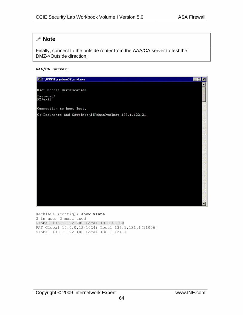
CCIE Security Lab Workbook Volume I Version 5.0 ASA Firewall
Copyright © 2009 Internetwork Expert www.INE.com64
Note
Finally, connect to the outside router from the AAA/CA server to test the DMZ->Outside direction:
AAA/CA Server:
Rack1ASA1(config)# show xlate 3 in use, 3 most used Global 136.1.122.200 Local 10.0.0.100 PAT Global 10.0.0.12(1024) Local 136.1.121.1(11006) Global 136.1.122.100 Local 136.1.121.1

CCIE Security Lab Workbook Volume I Version 5.0 ASA Firewall
Copyright © 2009 Internetwork Expert www.INE.com65
1.12 Static NAT and PAT • Clear any Previous NAT rules if needed. • Map the DMZ IP address 10.0.0.100 to the outside 136.X.122.100. • Configure Static PAT such that telnet sessions to the outside interface are
redirected to R1. • Configure Static PAT such that DNS requests sent to the ASA inside
interface are redirected to R2. Make sure inside hosts are translated when they go outside.
Configuration
Note
A static NAT rule establish bi-directional mapping between local and global IP addresses. Unlike a dynamic rule, which usually maps N local addresses to M global address, where N > M, the number of global addresses equals the number of local addresses within a static rule. Static translations are used for the following purposes:
1) To allow accessing a server located on the inside using a fixed global (outside) IP. The syntax would be:
static (<local-iface>,<global-iface>) <global-ip> <local-ip>
e.g.
static (inside,outside) 136.1.122.100 10.0.0.1
What this rules does, is establishes a bi-directional mapping between the local-ip and the global-ip. Note that in the rule, local-iface is the interface where local-ip resides, while global-ip should either be on the subnet shared by the global-iface or routed to the firewall appliance across the global-iface. This rule also allows the inside server to initiate connections to the outside and has its source IP translated to the global IP address. Now look at the following “extreme” rule:
static (inside,outside) interface 10.0.0.1
What it does, is uses the global interface IP (in this case – outside) and maps it to the local IP (10.0.0.1). Thus, all connections made to the outside IP of the ASA are redirected to the internal server. Of course, they should be permitted with an ACL prior to that. This will disable any services that ASA runs on the outside

CCIE Security Lab Workbook Volume I Version 5.0 ASA Firewall
Copyright © 2009 Internetwork Expert www.INE.com66
interface, by the way.
2) To redirect a particular port at the global IP to the port at the inside IP (aka Static PAT or port redirection). The syntax is:
static (<local-iface>,<global-iface>) {tcp|udp} <global-ip> <port> <local-ip> <port>.
e.g.
static (inside,outside) tcp 136.1.122.100 80 10.0.0.1 8080
would redirect all connections going to 136.1.122.100 port 80 to the inside IP 10.0.0.1 port 8080. You would usually use this rule when you have little or just one global IP address and would like to multiplex different services (e.g. FTP, WWW, DNS) between different internal services. It is also possible to redirect connections going to the ASA’s own interface:
static (inside,outside) tcp interface 80 10.0.0.1 80 static (inside,outside) tcp interface 21 10.0.0.2 21
This is a common construct when you only have a single global IP address assigned to the outside interface of the firewall. Note that static PAT does not allow the internal server to access the internal using the global IP address. You must define a dynamic NAT rule in order to allow the internal server to initiate connections on its own. For example:
static (inside,outside) tcp interface 80 10.0.0.1 nat (inside) 1 10.0.0.0 255.255.255.0 global (outside) 1 interface
This configuration allows any host on the inside to access the outside by having their source addresses translated using the firewall’s outside IP. At the same time, connections to the firewall’s outside interface port 80 are redirected to the server with the IP 10.0.0.1
3) Reverse redirection. Sometimes, you may want to redirect a connection going to an inside host to some outside destination. This is often called “routing simplification”, as it might be used in situations where inside hosts lack routing information, e.g. have no default gateway set, or have the default route pointing toward some other router (not the firewall).
For example, imagine you have a DNS server on the outside with the IP address 136.1.122.200 but you want the inside hosts to use the IP 10.0.0.200 to access the DNS server (e.g. the hosts have no default gateway set). The following

CCIE Security Lab Workbook Volume I Version 5.0 ASA Firewall
Copyright © 2009 Internetwork Expert www.INE.com67
“reverse” construct (local and global interfaces are “swapped”) would achieve the goal:
static (outside,inside) 10.0.0.200 136.1.122.200
The firewall will do Proxy-ARP for the IP address 10.0.0.200 on its inside interface, provided that 10.0.0.0/XX is the inside’s interface subnet. In other cases, this subnet should be explicitly routed to the firewall. Remember, that the inside hosts most likely need their sources translated when accessing the outside DNS. Thus, you may need to add a dynamic NAT rule as well:
nat (inside) 1 0 0 global (outside) 1 interface
to make the things work for you. Of course, it is possible to do reverse port redirection, for example:
static (outside,inside) tcp 21 interface 136.1.122.20 2021
Would redirect all connections going to the firewall “inside” interface port 21 to the outside host 136.1.122.20 port 2021. As usual, you may need an accompanying dynamic NAT rule to complete the configuration.
4) Block translation. You can use the netmask keyword along with the staticstatement. For example
static (inside,outside) 10.0.0.0 192.168.0.0 netmask 255.255.255.0
Will establish bi-direction mapping between the subnets 10.0.0.0/24 and 192.168.0.0/24 mapping 10.0.0.1 to 192.168.0.1 and so on.
If you have nat-control enabled in the firewall, you might need “identity” statements like:
static (inside,outside) 10.0.0.0 10.0.0.0 netmask 255.255.255.0
to permit anyone accessing the inside network 10.0.0.0/24 from the outside (provided that the outside ACL permits it and network 10.0.0.0/24 is routed across the firewall).
Note: When configuration static NAT/PAT, you must always add corresponding outside ACL entries to permit access from the outside to the inside hosts. This applies to any traffic that transits the firewall from lower to higher security zones.

CCIE Security Lab Workbook Volume I Version 5.0 ASA Firewall
Copyright © 2009 Internetwork Expert www.INE.com68
Now a few words on “extra” parameters to the static statement.
1) The first parameter is tcp <max_conn> [<max_half_open>] which is used as follows:
static (inside,outside) 192.168.1.100 10.0.0.100 tcp 500 100
or even without the keyword “tcp”
static (inside,outside) 192.168.1.100 10.0.0.100 500 100
This parameter is used to prevent DoS attacks against the corresponding IP address. This is a legacy way to configure the anti-DoS settings and is now superseded by MPF configurations. However, just FYI <max_conn> is the maximum number of concurrent TCP connections established to the mapped IP address. The other parameter <max_half_conn> specifies the maximum number of allowed embryonic connections – TCP connections that have not yet finished the 3-way TCP handshake. The goal is to prevent the resource starvation in the protected server and protect it against SYN-flooding attack. The default limit is set to zero for both parameters, which means unlimited number of connections.
You may also specify the maximum number of UDP sessions per static NAT entry, using the parameter udp <max_conn>. A UDP “session” is started once the first UDP packet towards the host is detected, and timed out after the amount of time specified using the command timeout udp. Of course, the preferred way to set the maximum number of connections is using MPF.
2) The second parameter is norandomseq. By default, the firewall inspects any TCP sessions and modifies TCP Initial Sequence Number (ISN) to a truly random value. This is need to prevent TCP connection hijaaking when a hacker might guess the ISN and inject seemingly correct packets into TCP flow. In some cases you may need to disable this option. Most commonly this is needed if the TCP session header is authenticated in some way, for example using the MD5 hash option. A good example is an authenticated BGP peering session. The other scenario is that there exist another firewall, that already has done the ISN randomization.
This option might be selectively enabled and disabled using the MPF as well, as we will see in special labs.
And last but not least. Static NAT configuration takes precedence other any other

CCIE Security Lab Workbook Volume I Version 5.0 ASA Firewall
Copyright © 2009 Internetwork Expert www.INE.com69
form of NAT configured. Therefore, it never collides with dynamically created NAT entries.
Our example has a sample for all basic forms of Static NAT, including static bi-directional NAT, port-redirection off the ASA interface and a reverse redirection. Plus, we illustrate the use of access-list to permit the access to the mapped addresses from the outside
ASA1: ! ! Clear the old NAT rules if any ! clear configure nat clear configure global clear configure static
! ! DMZ host ! static (dmz,outside) 136.1.122.100 10.0.0.100
! ! Telnet redirection ! static (inside,outside) tcp interface 23 136.1.121.1 23
! ! DNS redirection (reverse direction!) ! static (outside,inside) udp interface 53 136.1.122.2 53
! ! Translate inside->outside for DNS requests ! nat (inside) 1 0 0 global (outside) 1 interface
! ! ! clear configure access-list OUTSIDE_IN
! ! Access-list/Group to permit inbound connections ! access-list OUTSIDE_IN extended permit ip any host 136.1.122.100 access-list OUTSIDE_IN extended permit tcp any host 136.1.122.12 eq telnet ! access-group OUTSIDE_IN in interface outside

CCIE Security Lab Workbook Volume I Version 5.0 ASA Firewall
Copyright © 2009 Internetwork Expert www.INE.com70
Verification
Note
Verification is “simulation-based” – connect to the global addresses/ports using the telnet command.
Rack1R2#telnet 136.1.122.100 80 Trying 136.1.122.100, 80 ... Open
Rack1R2#disc 1 Closing connection to 136.1.122.100 [confirm]
Rack1R2#telnet 136.1.122.12 Trying 136.1.122.12 ... Open
Password required, but none set
[Connection to 136.1.122.12 closed by foreign host]
Note
Finally, we configure R2 to act as a DNS server and create a sample DNS hostname. We then configure R1 to use the firewall’s inside interface as the DNS server IP address. Note that even though the ping command fails, the name is correctly resolved, as the DNS packets are relayed to R2.
Rack1R2#conf t Enter configuration commands, one per line. End with CNTL/Z. Rack1R2(config)#ip dns server Rack1R2(config)#ip host TEST 136.1.122.2
Rack1R1#conf t Enter configuration commands, one per line. End with CNTL/Z. Rack1R1(config)#ip name-server 136.1.121.12 Rack1R1(config)#ip domain-lookup Rack1R1#ping TEST Translating "TEST"...domain server (136.1.121.12) [OK]
Type escape sequence to abort. Sending 5, 100-byte ICMP Echos to 136.1.122.2, timeout is 2 seconds: ..... Success rate is 0 percent (0/5)

CCIE Security Lab Workbook Volume I Version 5.0 ASA Firewall
Copyright © 2009 Internetwork Expert www.INE.com71
1.13 Dynamic Policy NAT • Clear any previous NAT rules if needed. • Telnet connections going outside should be PAT translated using the IP
address 136.X.122.100 • ICMP packets going outside should be PAT translated using the IP
address 136.X.122.101 • Use the access-lists TELNET and ICMP to distinguish two types of traffic. • Everything else should be PAT translated using the outside interface IP.
Configuration
Note
As we have seen before, NAT rules classify input traffic based on IP addresses solely. It is possible to add some policy decision, by using extended access-lists with the NAT rules. A NAT rules configure with an access-list will only translate packets matching this access-list. This allows you to define NAT translation rules based on destination IP addresses, protocols, port numbers and so on. The following NAT rule:
access-list HTTP_ONLY permit tcp any any eq 80
nat (inside) 1 access-list HTTP_ONLY global (outside) 1 interface
will only PAT-translate HTTP connections going outside. Policy NAT rules take precedence over regular NAT rules (however, static NAT/PAT is still more preferred) and therefore you may define a number of specific policy rules followed by a “wildcard” translation that matches all other types of traffic. Note that the command nat (inside) 0 access-list ACL is NOT a policy NAT rule (it is the NAT exempt rule), and will be discussed separately.
Our scenario utilizes two policy-NAT entries, defined for ICMP and telnet traffic. There is also a wildcard rule that translates everything else. Three PAT pools are defined for all three NAT rules.

CCIE Security Lab Workbook Volume I Version 5.0 ASA Firewall
Copyright © 2009 Internetwork Expert www.INE.com72
ASA1: ! ! Clear the old NAT rules if any ! clear configure nat clear configure global clear configure static
! ! Access-List to classify traffic (the policy) ! access-list ICMP extended permit icmp any any access-list TELNET extended permit tcp any any eq telnet ! nat (inside) 1 access-list ICMP nat (inside) 2 access-list TELNET nat (inside) 3 0 0
! ! Create 3 PAT pools for each NAT rule ! global (outside) 1 136.1.122.100 global (outside) 2 136.1.122.101 global (outside) 3 interface
! ! Permit the returning ping responses ! access-list OUTSIDE_IN extended permit icmp any any access-group OUTSIDE_IN in interface outside
Verification
Note
Verification procedure is simulation based. We generate ICMP and telnet packets and see if they are translated using the respective NAT pools.
Rack1R1#telnet 136.1.122.2 Trying 136.1.122.2 ... Open
User Access Verification
Password: cisco Rack1R2>
Rack1ASA1(config)# show xlate 1 in use, 10 most used PAT Global 136.1.122.101(1024) Local 136.1.121.1(11007)
Rack1R1#ping 136.1.122.2
Type escape sequence to abort.

CCIE Security Lab Workbook Volume I Version 5.0 ASA Firewall
Copyright © 2009 Internetwork Expert www.INE.com73
Sending 5, 100-byte ICMP Echos to 136.1.122.2, timeout is 2 seconds: !!!!! Success rate is 100 percent (5/5), round-trip min/avg/max = 4/4/4 ms
Rack1R1#
Rack1ASA1# show xlate 5 in use, 10 most used PAT Global 136.1.122.100(10) Local 136.1.121.1 ICMP id 1842 PAT Global 136.1.122.100(9) Local 136.1.121.1 ICMP id 1841 PAT Global 136.1.122.100(8) Local 136.1.121.1 ICMP id 1840 PAT Global 136.1.122.100(7) Local 136.1.121.1 ICMP id 1839 PAT Global 136.1.122.100(6) Local 136.1.121.1 ICMP id 1838

CCIE Security Lab Workbook Volume I Version 5.0 ASA Firewall
Copyright © 2009 Internetwork Expert www.INE.com74
1.14 Static Policy NAT and PAT • Make RIP passive on the ASA outside interface. • Redirect telnet connections going from 136.X.122.0/24 to the firewall
outside interface to R1. • Redirect HTTP connections going from 150.X.2.0/24 subnet of R2 to the
firewall outside interface to AAA/CA server. • Create and apply the necessary access-group to the outside interface.
Configuration
Note
Static NAT/PAT rules are commonly used to represent a local server via a global IP. What if we want to make the server appear under two different global IPs, depending on the outside hosts IP addresses (based on policy)? For example, let’s make the internal HTTP server 10.0.0.1 to appear as 172.16.1.1 to the outside hosts on the subnet 192.168.1.0/24. We first create a special ACL that defines the policy:
access-list POLICY permit tcp host 10.0.0.1 eq 80 192.168.1.0 255.255.255.0
In this access-list, the first <subnet> <mask> pair matches the internal server characteristics (IP and possibly port), and the second <subnet> <mask> match the outside hosts. We then create the static rule:
static (inside,outside) tcp 172.16.1.1 80 access-list POLICY
Which implements the above described policy NAT mapping. Note that in this rule, the mapped IP address MUST be configured along with the TCP port, to match the left part of the previously configured policy ACL. In general, the “mapped” part of the static policy rule should match the left side of the policy ACL, with the exception to the fact that the policy ACL contains the “local” IP address. For example, the following configuration is also valid
access-list POLICY2 permit ip host 10.0.0.2 192.168.2.0 255.255.255.0 access-list POLICY2 permit ip host 10.0.0.2 192.168.3.0 255.255.255.0
static (inside,outside) 172.16.1.2 access-list POLICY2
but this time, the left par of the access-list is IP-only and thus matches the

CCIE Security Lab Workbook Volume I Version 5.0 ASA Firewall
Copyright © 2009 Internetwork Expert www.INE.com75
“mapped” part of the static rule.Note that you cannot define the following rules:
static (inside,outside) tcp 172.16.1.1 80 access-list POLICY1 static (inside,outside) tcp 172.16.1.1 80 access-list POLICY2
even though the ACLs are different. For static rules, the left (“mapped”) part of the rule must be different - otherwise the firewall considers it to be a duplicate.
Our example requires configuring two policy static NAT rules for two inside hosts. We redirect telnet/HTTP sessions terminated on the ASA’s outside interface based on the source IP addresses of the originated hosts.
ASA1:
clear configure nat clear configure global clear configure static
! ! Access-list to match Telnet traffic from VLAN122 ! access-list VLAN122 permit tcp host 136.1.121.1 eq 23 136.1.122.0 255.255.255.0
! ! Access-list to match HTTP traffic from R2’s Lo0 ! access-list LO0 permit tcp host 10.0.0.100 eq 80 150.1.2.0 255.255.255.0
! ! Static Policy PAT for VLAN122 Telnet ! static (inside,outside) tcp interface 23 access-list VLAN122
! ! Static Policy PAT for LO0 HTTP ! static (dmz,o) tcp interface 80 access-list LO0
! ! Outside ACL to permit incoming sessions ! access-list OUTSIDE_IN permit tcp any host 136.1.122.12 eq 80 access-list OUTSIDE_IN permit tcp any host 136.1.122.12 eq 23 ! access-group OUTSIDE_IN in interface outside

CCIE Security Lab Workbook Volume I Version 5.0 ASA Firewall
Copyright © 2009 Internetwork Expert www.INE.com76
Verification
Note
To verify, connect to the outside interface of the firewall on ports 23 and 80. Use different telnet source interface when performing the HTTP connection simulation.
Rack1R2#telnet 136.1.122.12 Trying 136.1.122.12 ... Open
Password required, but none set
[Connection to 136.1.122.12 closed by foreign host]
Rack1R2#telnet 136.1.122.12 80 /source-interface loopback 0 Trying 136.1.122.12, 80 ... Open
HTTP/1.1 400 Bad Request Server: Microsoft-IIS/5.0 Date: Mon, 08 Jan 2007 12:10:00 GMT Content-Type: text/html Content-Length: 87
<html><head><title>Error</title></head><body>The parameter is incorrect. </body></html> [Connection to 136.1.122.12 closed by foreign host]
Note
Now check the detailed information in the NAT translation table. Note that the telnet session has been redirected to R1, while the HTTP session has been redirected to the AAA/CA server.
Rack1ASA1(config)# show xlate debug 2 in use, 10 most used Flags: D - DNS, d - dump, I - identity, i - dynamic, n - no random, r - portmap, s - static TCP PAT from inside:136.1.121.1/23 to outside(VLAN122):136.1.122.12/23 flags sr idle 0:00:24 timeout 0:00:00 TCP PAT from dmz:10.0.0.100/80 to outside(LO0):136.1.122.12/80 flags sr idle 0:00:17 timeout 0:00:00
CCIE Security Lab Workbook Volume I Version 5.0 ASA Firewall
Copyright © 2009 Internetwork Expert www.INE.com77
1.15 Identity NAT and NAT Exemption • Clear any previous NAT rules if needed and re-enable RIPv2 announces
on the outside interface of the firewall. • Configure the firewall such that the network 136.X.121.0/24 is translated
to itself. • Configure the firewall so that no NAT translation is performed for the
AAA/CA server 10.0.0.100.
Configuration
Note
Identity NAT configuration has the following syntax:
nat (<interface>) 0 <subnet> <mask>e.g. nat (inside) 0 10.0.0.0 255.255.255.0
What this rule says, is that all packets matching the <subnet> <mask> pair entering on the <interface> and leaving out of any interface would have translation slots created but with unmodified source IP addresses. Note that the Identity NAT rule doesn’t have any corresponding global NAT pool associated, and therefore applies to all outgoing interfaces. For the duration of the translation entry, you may access the inside hosts using their inside IP addresses (of course, if the outside access-list permits such access). However, in order to access an inside host that has been identity-translated you must wait for this host to initiate some traffic first. You may configure as much identity NAT rules as you want, but consider using static NAT rules if you are looking for bi-directional access. The following sample rule will allow any hosts on the inside to access the outside with unmodified source addresses, provided that the inside network is advertised to the outside via IGP:
nat (inside) 0 0 0
NAT Exemption rule has the following syntax:
nat (<interface>) 0 <ACCESS-LIST>
Here <ACCESS-LIST> is used to match traffic as following:
permit ip <local-subnet> <local-mask> <global-subnet> <global-mask>
CCIE Security Lab Workbook Volume I Version 5.0 ASA Firewall
Copyright © 2009 Internetwork Expert www.INE.com78
For example, let exempt all traffic exchange between 10.0.0.0/24 and the host 192.168.1.1 from being NAT-translated:
access-list EXEMPT permit ip 10.0.0.0 255.255.255.0 host 192.168.1.1 nat (inside) 0 access-list EXEMPT
The purpose is to exclude certain flows of traffic from translation. Any packets (going from inside or outside) matching the NAT exemption ACLs do not require NAT translation entries to be permitted by the firewall (provided that the filtering ACLs do not block them, of course). Note that this allows the outside hosts to initiate connections to the inside hosts, if permitted by the ACL, even if nat-control is enabled. Pay attention to the ACL used with NAT-exemption. The firewall will ignore any port/protocol statements (e.g. permit tcp) and will only match based on source/destination IP addresses specified in the access-list. NAT exemption takes precedence over any dynamic NAT translation (but not the static NAT rules).
You will generally see NAT exemption used with VPN scenarios. For example, imagine you have remote site connected to the local via an IPsec tunnel. The remote network is 192.168.2.0/24 and the local network is 192.168.1.0/24. The IPsec tunnel is configured to encrypt traffic flows between the above mentioned networks. Now imagine you need to configure the Internet access for the subnet 192.168.1.0/24 and you apply the following rules:
nat (inside) 1 192.168.1.0 255.255.255.0 global (outside) 1 interface
The above rules will also apply to traffic from 192.168.1.0/24 going to 192.168.2.0/24, and will prevent it from being IPsec encrypted. In order to allow the encryption of the inter-site traffic, apply the following NAT exemption rule:
access-list VPN_TRAFFIC permit ip 192.168.1.0 255.255.255.0 192.168.2.0 255.255.255.0 nat (inside) 0 access-list VPN_TRAFFIC
Since NAT exemption takes precedence over dynamic/static NAT rules, this statement will do the trick. In addition to exempting the traffic flows from NAT, it will also allow the subnet 192.168.2.0/24 to initiate connections to the subnet 192.168.1.0/24 without any special NAT rules, even if nat-control is enabled.
The good thing about NAT exemption is that it is policy based, unlike the identity NAT. Those methods serve different purposes, and you might want to use them in appropriate situations.

CCIE Security Lab Workbook Volume I Version 5.0 ASA Firewall
Copyright © 2009 Internetwork Expert www.INE.com79
1) Identity NAT: When you only need the inside hosts to access outside with source IPs unmodified. You may also simply disable nat-control to accomplish this. 2) NAT Exemption: When you need to provide bi-directional connectivity and exclude only certain flows of traffic from being NAT translated. Commonly used with VPN scenarios and NAT-control.
In our scenario, we allow the AAA/CA Server to access any destination without creating any NAT entries. At the same time, the inside hosts will have identity NAT entries created in the translation table.
ASA1:nat-control
! ! Allow R2 to learn about the inside/DMZ networks ! router rip no passive-interface outside
! ! Identity NAT ! nat (inside) 0 136.1.121.0 255.255.255.0
! ! Access-List to match traffic from AAA/CA server ! access-list SERVER extended permit ip host 10.0.0.100 any
! ! NAT Exemption ! nat (dmz) 0 access-list SERVER
clear configure access-list OUTSIDE_IN
! ! Access-List to perform some basic testing ! access-list OUTSIDE_IN ext permit ip any any access-group OUTSIDE_IN in interface outside
Verification
Note
Try pinging R1 and the AAA/CA server from R2. Even though the ACLs permit ICMP packets, you can only reach the AAA/CA server, as it has been exempted from NAT.

CCIE Security Lab Workbook Volume I Version 5.0 ASA Firewall
Copyright © 2009 Internetwork Expert www.INE.com80
Rack1R2#ping 10.0.0.100
Type escape sequence to abort. Sending 5, 100-byte ICMP Echos to 10.0.0.100, timeout is 2 seconds: !!!!! Success rate is 100 percent (5/5), round-trip min/avg/max = 1/2/4 ms
Rack1R2#ping 136.1.121.1
Type escape sequence to abort. Sending 5, 100-byte ICMP Echos to 136.1.121.1, timeout is 2 seconds: ..... Success rate is 0 percent (0/5)
Note
Now ping from R1 to create an identity NAT entry, and then ping R1 from R2 again. This time the operation is successful, as now the NAT translation entry exists.
Rack1R1#ping 136.1.122.2
Type escape sequence to abort. Sending 5, 100-byte ICMP Echos to 136.1.122.2, timeout is 2 seconds: !!!!! Success rate is 100 percent (5/5), round-trip min/avg/max = 4/4/4 ms Rack1R1#
Rack1R2#ping 136.1.121.1
Type escape sequence to abort. Sending 5, 100-byte ICMP Echos to 136.1.121.1, timeout is 2 seconds: !!!!! Success rate is 100 percent (5/5), round-trip min/avg/max = 1/3/4 ms Rack1R2#
Note
Finally check the translation table contents and see that R1’s IP has been preserved.
Rack1ASA1(config)# show x 1 in use, 10 most used Global 136.1.121.1 Local 136.1.121.1

CCIE Security Lab Workbook Volume I Version 5.0 ASA Firewall
Copyright © 2009 Internetwork Expert www.INE.com81
1.16 Outside Dynamic NAT • Prevent R1 from learning about the outside destinations via RIP. • Hosts from the outside with the source IP addresses from the subnet
136.X.122.0/24 accessing the hosts on the inside should have their IP addresses translated using the inside interface IP address.
• Ensure that hosts on the inside are still able to access the AAA/CA server on the DMZ interface.
Configuration
Note
Outside Dynamic NAT is a feature that you would rarely need in real world. Generally, it does that same as the classic dynamic NAT, but applies translations to the IP addresses of the outside hosts accessing the inside destinations. You might occasionally need this in situations where your inside servers have no information about the outside hosts behind your firewall. For example, they may have their default gateway set to some other host, or may not have any default gateway set at all. Of course, you may use static NAT rules to “simplify” routing in this situation, but they might not cover the whole source address space if it is too big (e.g. hundreds of hosts). You may configure like following:
nat (outside) 1 0 0 outside global (inside) 1 interface
static (inside,outside) 136.1.122.100 10.0.0.1
to allow all outside hosts accessing the global IP 136.1.122.100 to look like they all belong to the subnet 10.0.0.0/24 (by being PAT translated to the IP address of the ASA’s inside interface).
There is one major side-effect of the outside NAT. As soon as you configure at least one outside NAT rule, your inside hosts will loose access to the outside destinations, unless they have static NAT/PAT entries explicitly configured. This makes sense, as the outside NAT scenario assumes the inside network to be “blind” about the outside world. More precisely, when you configure at least one outside dynamic NAT entry, you MUST create a static NAT entry in order to access a host on the lower security interface from a host on the higher security interface.
Not only this – you might need some dynamic NAT rules to allow accessing the outside servers from the inside as well. All this burden because the outside NAT scenario is a very rare case, when the inside network thinks it is the only one that exists in the world.

CCIE Security Lab Workbook Volume I Version 5.0 ASA Firewall
Copyright © 2009 Internetwork Expert www.INE.com82
In our scenario, by configuring the dynamic outside NAT rule, we loose access from the inside hosts to the AAA/CA server, until the moment we create a “reverse” static NAT entry. In addition to the static reverse NAT entry, we need to create a dynamic NAT rule to permit access from the inside to DMZ.
ASA1:nat-control ! router rip passive-interface inside no passive-interface outside
! ! Outside NAT config, VLAN122 is PATed using the inside iface ! nat (outside) 1 136.1.122.0 255.255.255.0 outside global (inside) 1 interface
! ! “Reverse” static NAT for the AAA/CA server. ! static (dmz,inside) 136.1.121.100 10.0.0.100
! ! Dynamic NAT to access DMZ from inside. ! Required to reach the static mapping for AAA/CA server. ! nat (inside) 1 0 0 global (dmz) 1 interface
clear configure access-list OUTSIDE_IN ! ! Access-List to perform some basic testing from outside ! access-list OUTSIDE_IN ext permit ip any any access-group OUTSIDE_IN in interface outside
Verification
Note
Ping the IP address of R1 from R2. Look at the translation table and notice that R2’s IP address has been translated using the ASA’s inside interface IP address.
Rack1R2#ping 136.1.121.1
Type escape sequence to abort. Sending 5, 100-byte ICMP Echos to 136.1.121.1, timeout is 2 seconds: !!!!!

CCIE Security Lab Workbook Volume I Version 5.0 ASA Firewall
Copyright © 2009 Internetwork Expert www.INE.com83
Success rate is 100 percent (5/5), round-trip min/avg/max = 1/2/4 ms Rack1R2#
Rack1ASA1(config)# show xlate 7 in use, 10 most used Global 136.1.121.100 Local 10.0.0.100 PAT Global 136.1.121.12(5) Local 136.1.122.2 ICMP id 3200 PAT Global 136.1.121.12(4) Local 136.1.122.2 ICMP id 3199 PAT Global 136.1.121.12(3) Local 136.1.122.2 ICMP id 3198 PAT Global 136.1.121.12(2) Local 136.1.122.2 ICMP id 3197 PAT Global 136.1.121.12(1) Local 136.1.122.2 ICMP id 3196
Note
Now go to R1, and try pinging the IP address on the inside subnet that corresponds to the mapped AAA/CA server. Since we don’t have any ingress ACL on the DMZ interface, the ASA will drop the returning ICMP echo-responses.
Rack1R1#ping 136.1.121.100
Type escape sequence to abort. Sending 5, 100-byte ICMP Echos to 136.1.121.100, timeout is 2 seconds: ..... Success rate is 0 percent (0/5)
Note
However, we should be still able to initiate a connection from inside to DMZ, as this is inspected and permitted by the ASA engine.
Rack1R1#telnet 136.1.121.100 80 Trying 136.1.121.100, 80 ... Open
HTTP/1.1 400 Bad Request Server: Microsoft-IIS/5.0 Date: Mon, 08 Jan 2007 14:06:26 GMT Content-Type: text/html Content-Length: 87
<html><head><title>Error</title></head><body>The parameter is incorrect. </body></html> [Connection to 136.1.121.100 closed by foreign host]
CCIE Security Lab Workbook Volume I Version 5.0 ASA Firewall
Copyright © 2009 Internetwork Expert www.INE.com84
1.17 DNS Doctoring using “Alias” • Clear any previously configured address translation rules and make sure
RIP is enabled on all the inside interface again. • Configure R2 to act as DNS server. Create a new host entry for the name
“WWW” with address 136.X.122.100. • Hosts on the DMZ subnet using R2 as their DNS server should see the
name “WWW” resolved to the IP address of the AAA/CA server. • Use the “alias” command in the ASA to accomplish this.
Configuration
Note
The legacy alias command was designed to work like a half-functioning static command. When you configure
alias (<interface>) <original-ip> <redirected-ip> <netmask>
the security appliance will check if the <original-ip> belongs to the subnet of the <interface>. If it does, the firewall will install an ARP entry to pull traffic to <original-ip> through itself. As soon as the packet enters <interface> destined to <original-ip> the firewall will rewrite the destination IP address with the <redirected-ip> and forward it further to the new IP address – effectively implementing the aliasing function. The source IP might be modified if there are any NAT rules configured (and required by NAT-control). Note that the <netmask> option allows you to create a whole block of aliases, for example by setting the netmask 255.255.255.224 you will get about 30 aliases installed in the ASA.
The alias command only works one-way, so the traffic initiated from <redirected-ip> back to to the <interface> it will no be source-rewritten to <original-ip>. Of course, nowadays you would implement this redirection using the reverse static NAT command, which works symmetrically.
The other important feature of the legacy alias command is automatic DNS rewrite. When a DNS A-record response is returned across the firewall to the <interface> and the IP address in the DNS packet matches the <redirected-ip> the firewall will change it to <original-ip>. This is called “DNS Doctoring”, and basically it was the most common use for the alias command. Look at the current scenario. The AAA/CA server is located on the DMZ interface. The global DNS server on the outside reports the AAA/CA server IP as 136.X.122.100. Now imagine there are other hosts on the DMZ segment, trying to access the AAA/CA server via its name “WWW” and using the outside

CCIE Security Lab Workbook Volume I Version 5.0 ASA Firewall
Copyright © 2009 Internetwork Expert www.INE.com85
DNS server. Of course they will try to get to 136.X.122.100 and fail. However, if we configure the firewall for DNS doctoring using the command:
alias (dmz) 10.0.0.100 136.1.122.100 255.255.255.255
Then the responses from the DNS server (simulated by R2) will match the alias rule and 136.1.122.100 will be changed to 10.0.0.100. Thus the DMZ hosts using the outside DNS server will successfully access the local server using the name “WWW”.
One last thing to remember – the alias command creates a proxy-ARP entry in the firewall by default. Therefore, if you only use it for DNS doctoring, disable Proxy-ARP by using the command sysopt noproxyarp dmz, to avoid occasional IP address conflict messages. Also, if you’re wondering about a way to disable DNS rewrites, there are two ways:
1) Legacy: using the sysopt nodnsalias {inboud|outbound} where inbound means direction from a lower security level to a higher security level interface and vice-versa for outbound. 2) Modern: Modify the default MPF DNS inspection policy map (DNS inspection is enabled by default)
policy-map type inspect dns preset_dns_map parameters no nat-rewrite
ASA1:nat-control ! router rip no passive-interface inside no passive-interface outside
! ! Clear any previous NAT rules ! clear configure nat clear configure static clear configure global
! ! DNS doctoring with alias. This rule will never pull ! any actual traffic, but will do DNS rewrites ! alias (dmz) 10.0.0.100 136.1.122.100 255.255.255.255
! ! The following NAT rules are required for DNS ! requests to get to R2 (NAT-control is enabled).

CCIE Security Lab Workbook Volume I Version 5.0 ASA Firewall
Copyright © 2009 Internetwork Expert www.INE.com86
! nat (dmz) 1 0 0 global (outside) 1 interface
! ! Needed to disable the firewall to Proxy-ARP on its DMZ interface ! sysopt noproxyarp
R2: ! ! R2 emulates a DNS server ! ip dns server ip host WWW 136.1.122.100 ip host TEST 136.1.122.2
Verification
Note
In order to verify the scenario, assign the test PC to the same VLAN as the DMZ interface:
SW2: interface FastEthernet 0/20 switchport host switchport access vlan 120
Configure the TCP/IP settings appropriately, using the ASA as the default gateway and R2 as the DNS server.

CCIE Security Lab Workbook Volume I Version 5.0 ASA Firewall
Copyright © 2009 Internetwork Expert www.INE.com87
Note
Now run the nslookup utility and resolve two names: “TEST” and “WWW”. Note that the second name translates to the DMZ IP address of the AAA/CA server.

CCIE Security Lab Workbook Volume I Version 5.0 ASA Firewall
Copyright © 2009 Internetwork Expert www.INE.com88

CCIE Security Lab Workbook Volume I Version 5.0 ASA Firewall
Copyright © 2009 Internetwork Expert www.INE.com89
1.18 DNS Doctoring using “Static” • Modify the solution of the previous task to use the “static” command
instead of the legacy “alias”.
Configuration
Note
As the static command replaced the legacy alias, it was natural to incorporate the DNS rewrite feature into this command. When you specify the dns keyword with the command
static (<local-iface>,<global-iface>) <global-ip> <local-ip> dns
The firewall will inspect the following DNS packets:
1) Going from <global-iface> to <local-iface> and having <global-ip> inside the DNS A-record contents. The <global-ip> will be changed to <local-ip>.
2) Going from <local-iface> to <global-iface> and carrying <local-ip> inside the DNS A-record. The <local-ip> will be replaced with <global-ip>.
Therefore, the DNS fixup will be changing the “point of view” inside the DNS responses. Looking at our scenario, the DNS server is located on the outside, and the command is:
static (dmz,outside) 136.1.122.100 10.0.0.100 dns
Not only does this commands establish a bi-directional mapping between 10.0.0.100 and 136.1.122.100 but it also enables DNS rewrites. When the DNS server on the outside responds to a host on the DMZ with a DNS A-record for “WWW” containing the IP 136.1.122.100 the firewall replaces it with the IP 10.0.0.100. Thus, all hosts on the DMZ segment using the outside DNS server will get referred to the correct IP address.
Imagine there is a DNS server on the DMZ, which would respond with the name “WWW” mapped to 10.0.0.100. Next there is a host on the outside that tries to resolve the name “WWW” using the DNS server on the DMZ segment. The firewall will intercept the DNS response (going DMZ->Outside), and replace

CCIE Security Lab Workbook Volume I Version 5.0 ASA Firewall
Copyright © 2009 Internetwork Expert www.INE.com90
10.0.0.100 with the IP 136.1.122.100, telling the outside host to access the correct IP address that translates to the actual AAA/CA server.
ASA1:nat-control
! ! remove the old configuration ! clear configure alias clear configure nat clear configure static clear configure global
! ! DNS doctoring with “static” ! static (dmz,outside) 136.1.122.100 10.0.0.100 dns
! ! The following NAT rules are required for DNS ! request to get to R2 (with nat-control enabled) ! nat (dmz) 1 0 0 global (outside) 1 interface
Verification
Note
Repeat the same steps you have performed to verify the previous task.

CCIE Security Lab Workbook Volume I Version 5.0 ASA Firewall
Copyright © 2009 Internetwork Expert www.INE.com91
1.19 Fragmented Traffic • Permit ICMP traffic through the firewall. • Disable fragmented packets on “DMZ” and “Outside” interfaces.
Configuration
Note
Fragmented IP traffic presents a potentially serious security threat. First of all, fragment reassembly code in many OSes has been long time most vulnerable to numerous bugs, exposing networks to the attacks such as Ping of Death. Secondly, fragmented traffic puts higher CPU/Memory burden on the end hosts, as it requires them to create large buffers (64K to potentially fit any fragment size) for packet reassembly and keep them for potentially long time, while waiting for all packet fragments. And lastly, it is a common technique to use fragmented traffic in order to bypass security checks (such as IPS or firewall) by breaking malicious packets into smaller fragments (this might let bypass simple firewalls, for example).
Even if it is a good practice to avoid traffic fragmentation at any cost, it is not possible in some situations. Two well-know examples are the use of NFSv2 (Sun’s Network File System) which transports data blocks in large UDP packets and VPN-protected traffic, which might exceed network MTU due to encryption/tunneling overheads.
The ASA firewall implements packet reassembly technique in order to perform deep inspection of fragmented traffic. The firewall does not permit a fragmented packet through, until it fully assembles it and verifies its contents. By default, the first fragment is delayed for the duration set by fragment timeout <N> command (5 seconds by default) until all fragments are received and assembled. If the timeout expires before all fragments arrive, the packet is discarded. The firewall will accept at maximum of fragment chain <limit> [interface] fragments on the particular interface, with the default being of 24 fragments. If the number of fragments exceeds the limit, the packet is discarded. Thus, if you want to disable fragmented packets at all, use the command fragment chain 1 to instruct the firewall dropping all fragmented packets (more than 1 fragment). Finally, all fragments are stored in a system-wide re-assembly buffer, with the size set using the command fragment size <N> where <N> is the maximum number of packets held in the buffer.
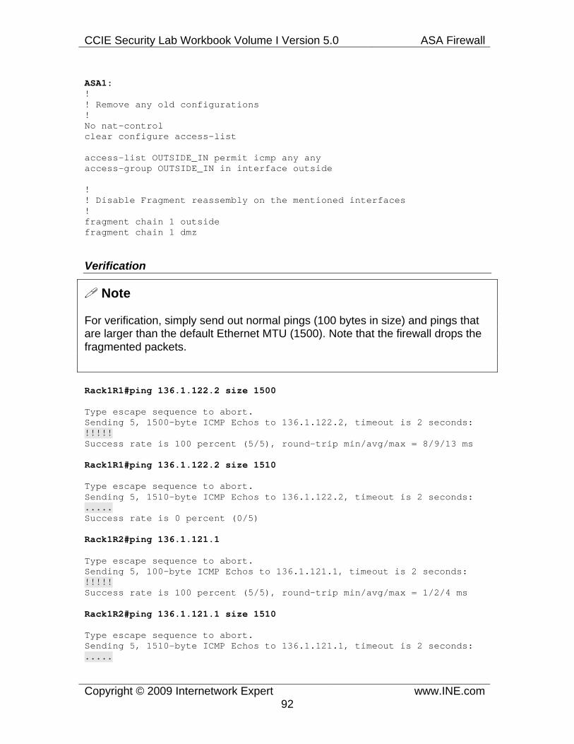
CCIE Security Lab Workbook Volume I Version 5.0 ASA Firewall
Copyright © 2009 Internetwork Expert www.INE.com92
ASA1: ! ! Remove any old configurations ! No nat-control clear configure access-list
access-list OUTSIDE_IN permit icmp any any access-group OUTSIDE_IN in interface outside
! ! Disable Fragment reassembly on the mentioned interfaces ! fragment chain 1 outside fragment chain 1 dmz
Verification
Note
For verification, simply send out normal pings (100 bytes in size) and pings that are larger than the default Ethernet MTU (1500). Note that the firewall drops the fragmented packets.
Rack1R1#ping 136.1.122.2 size 1500
Type escape sequence to abort. Sending 5, 1500-byte ICMP Echos to 136.1.122.2, timeout is 2 seconds: !!!!! Success rate is 100 percent (5/5), round-trip min/avg/max = 8/9/13 ms
Rack1R1#ping 136.1.122.2 size 1510
Type escape sequence to abort. Sending 5, 1510-byte ICMP Echos to 136.1.122.2, timeout is 2 seconds: ..... Success rate is 0 percent (0/5)
Rack1R2#ping 136.1.121.1
Type escape sequence to abort. Sending 5, 100-byte ICMP Echos to 136.1.121.1, timeout is 2 seconds: !!!!! Success rate is 100 percent (5/5), round-trip min/avg/max = 1/2/4 ms
Rack1R2#ping 136.1.121.1 size 1510
Type escape sequence to abort. Sending 5, 1510-byte ICMP Echos to 136.1.121.1, timeout is 2 seconds: .....

CCIE Security Lab Workbook Volume I Version 5.0 ASA Firewall
Copyright © 2009 Internetwork Expert www.INE.com93
Success rate is 0 percent (0/5)
1.20 Handling IDENT Issues • Configure the firewall to quickly terminate the IDENT lookup sessions
going from outside for TCP sessions initiated by inside users. • Consider both users translated using identity mappings and to the outside
interface IP address.
Configuration
Note
IDENT is the simple protocol that is designed to disclose the “owner” of the active TCP connection. This is how IDENT works:
1) On a user’s machine, a special IDENT daemon is running and listening on port 113. 2) When a user makes an outbound connection, the remote server might initiate reverse IDENT connection to the user’s IP address and port 113, asking for the information on the TCP connection “owner” (to record it in the system logs). 3) The daemon returns the information and the server permits the original user’s connection. 4) If for some reason the IDENT daemon does not respond, it’s up to the server to decide the further connection’s fate. Nowadays, most servers would still permit the connection.
IDENT protocol is clearly unsecure and unreliable. It might work in situations where the user has no admin privileges over the machine he works from. In addition to that, it requires that the user is not located behind any sort of NAT or firewall as the translating/filtering device might not properly handle the IDENT lookup. However, still some applications (e.g. sendmail and some FTP dameons) continue to use IDENT lookups with their default configuration, even though they don’t deny the hosts not running the IDENT process.
Now imagine that a user behind the ASA firewall connects to the server that does IDENT lookups. There might be two situations:
1) User is NAT translated using the IP that “belongs” to the ASA firewall. In this case, the reverse IDENT lookup will terminate at the ASA firewall. By default, the ASA simply discards TCP SYN packets sent to the ports it is not listening on.
2) User’s IP has not been changed by the firewall. In this case, the IDENT session will be attempted to the original user’s IP address. Most likely your firewall does not permit such connections, so the TCP SYN packets will be

CCIE Security Lab Workbook Volume I Version 5.0 ASA Firewall
Copyright © 2009 Internetwork Expert www.INE.com94
silently discarded.
In both cases, the original server will have to wait for reverse IDENT TCP connection to time out, before allowing the original connection. This will result in horrible delays to the end user. If only the firewall would send TCP RST response instead of discarding the packets, the server would know that IDENT lookup fails immediately, and will present user with the service prompt. You may allow such “reset” behavior using two commands.
service resetinbound service resetoutside
The first one will send TCP resets for sessions that are denied, but do not terminate on the firewall. The second one will instruct the ASA to send TCP RSTs for the sessions that are rejected by the firewall itself. Together, those two commands will make the firewall “less stealth” but will make end-users’s life much easier.
ASA1: ! ! Reset TCP connections denied on outside interface ! or denied inbound. ! service resetinbound service resetoutside
Verification
Note
There is no easy way to verify this task, unless you have a server that does reverse IDENT lookups.

CCIE Security Lab Workbook Volume I Version 5.0 ASA Firewall
Copyright © 2009 Internetwork Expert www.INE.com95
1.21 BGP across the Firewall
• Ensure the ASA firewall runs in NAT controlled mode and RIPv2 is active on all interfaces.
• R1 and R2 are pre-configured for eBGP peering across the firewall. • Both routers use their Loopback0 interfaces to source the BGP session. • Authenticate the BGP session using the password of “CISCO”. • Ensure that R2 is allowed to initiate a BGP sessions to R1.
Configuration
Note
Even though the security exam is not going to test thorough knowledge of BGP, still some aspects of this protocol are important. In this task, we are mostly concerned with BGP session establishment.
When two devices peer via BGP, they both attempt to establish a TCP session targeted at the remote port 179. After that, one of the sessions is dropped, and the remaining is used. In case of the ASA firewall, that means you are not always required the permit inbound BGP sessions across the firewall, since the inside router will initiate and establish the TCP connection. However, the scenario explicitly asks for the outside router to be able to initiate the BGP session, and thus we configure the outside ACL respectively.
Next, in the nat-control mode we need a static NAT entry for the inside router. Note that we cannot change the IP address of the peer, as we are instructed to use BGP MD5 authentication. This authentication method is implemented via a TCP option, which carries the MD5 hash value. The secure hash is taken over full IP and TCP header, and thus changing the IP addresses is not allowed.
Finally, as we remember, the firewall performs TCP ISN (Initial Sequence Number) randomization, which is not allowed when the MD5 authentication method is used. You can disable the randomization using the legacy syntax static (…,…) IP1 IP2 norandomseq or using the modern MPF framework configuration, as demonstrated in the solution. The detailed discussion of the MPF syntax is outside the scope of this particular scenario, but you can take note that it is applied via a special tcp_map construct. In addition to disabling the randomization of the ISN, we also permit TCP Option 19, which is used to carry the actual MD5 authentication hash. We apply the TCP map only to the BGP traffic by creating a special class-map that only matches BGP packets (TCP source/destination port 179).

CCIE Security Lab Workbook Volume I Version 5.0 ASA Firewall
Copyright © 2009 Internetwork Expert www.INE.com96
The IOS-side configuration is very basic, as compared to the ASA’s config.
ASA1: ! ! Remove the old configurations ! clear nat clear global clear static clear access-list
! ! Ensure full routing reachability ! router rip no passive-interface inside no passive-interface outside ! nat-control
! ! Map R1’s Loopback0 to itself ! static (inside,outside) 150.1.1.1 150.1.1.1 ! access-list OUTSIDE_IN permit tcp any any eq bgp access-group OUTSIDE_IN in interface outside
! ! Allow BGP MD5 Authentication option ! tcp-map BGP_MD5 tcp-options range 19 19 allow ! ! BGP traffic ! access-list BGP_MD5 permit tcp any any eq bgp access-list BGP_MD5 permit tcp any eq bgp any
! ! L3 Class-Map for BGP traffic ! class-map BGP_MD5 match access-list BGP_MD5
! ! Inspection map ! policy-map global_policy class BGP_MD5 set connection advanced-options BGP_MD5 set connection random-sequence-number disable !

CCIE Security Lab Workbook Volume I Version 5.0 ASA Firewall
Copyright © 2009 Internetwork Expert www.INE.com97
service-policy global_policy global
R1: router bgp 1 neighbor 150.1.2.2 password CISCO
R2: router bgp 2 neighbor 150.1.1.1 password CISCO
Verification
Note
Issue the show ip bgp summary command to make sure that the peering session is alive. The value under State/PfxRcv should be numeric, and not something like “Active” or “Idle” which usually means broken BGP peering session.
Rack1R2#show ip bgp summary <snip>
Neighbor V AS MsgRcvd MsgSent TblVer InQ OutQ Up/Down State/PfxRcd 150.1.1.1 4 1 19 16 2 0 0 00:02:01 1

CCIE Security Lab Workbook Volume I Version 5.0 ASA Firewall
Copyright © 2009 Internetwork Expert www.INE.com98
1.22 Stub Multicast Routing
• The ASA firewall connects stub multicast area on the “Inside” interface to the multicast-capable network behind R2.
• Configure the appliance to act as a proxy agent for IGMP join/leave messages on its inside interface.
• Ensure the RPF interface for unknown destinations is the outside interface.
• On R1, join the Ethernet interface to group 239.0.0.1 and make sure R2 can ping it.
Configuration
Note
Multicast routing is a complicated topic that could not be fully covered within the scope of the Security exam. We are going to have a brief discussion of the multicast routing and its support by the ASA firewall appliance.
Unlike classic unicast IP traffic, multicast flows have many recipients (subscribers). This requires totally different packet delivery method, as opposed to hop-by-hop destination based forwarding. Multicast traffic is distinguished by the destination IP address in range 224.0.0.0-239.255.255.255 (every such address is called “multicast group”). When a network is configured for multicast routing, it accepts such packets and “floods” them towards all subscribed members of the particular group. This “flooding” procedure is the core of the multicast traffic delivery.
When a new member wants to join a multicast group, it uses special protocol called IGMP (Internet Group Membership Protocol) to signal to its default router that it wants to join the group. The router, that is a part of the multicast capable network, will further interact with other routers to let them know that a new member needs the multicast feed.
When a multicast packet goes through the network, every router performs the so-called RPF (Reverse Path Forwarding) check on the packet, to prevent routing loops. The RPF procedure takes the source IP address of the packet and verifies that the shortest path towards the source IP is across the interface that packet was received on. This ensures that packet is not looped but correctly received from the respective upstream node. In other case, the packet is discarded. If the RPF check was successful, the firewall inspects the list of the downstream interfaces that received subscription signals for the packet’s multicast group. If there are any, the packet is replicated and forwarded downstream. This procedure is repeated until the packet is delivered to all terminal (leaf) nodes in
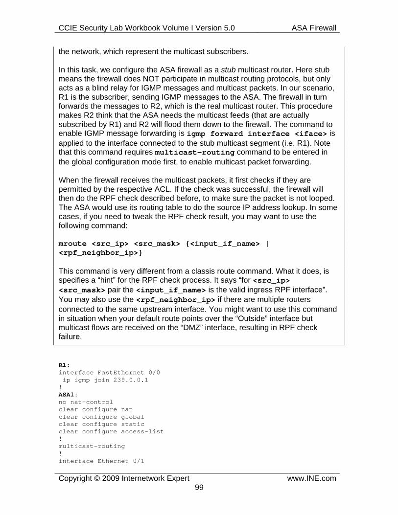
CCIE Security Lab Workbook Volume I Version 5.0 ASA Firewall
Copyright © 2009 Internetwork Expert www.INE.com99
the network, which represent the multicast subscribers.
In this task, we configure the ASA firewall as a stub multicast router. Here stub means the firewall does NOT participate in multicast routing protocols, but only acts as a blind relay for IGMP messages and multicast packets. In our scenario, R1 is the subscriber, sending IGMP messages to the ASA. The firewall in turn forwards the messages to R2, which is the real multicast router. This procedure makes R2 think that the ASA needs the multicast feeds (that are actually subscribed by R1) and R2 will flood them down to the firewall. The command to enable IGMP message forwarding is igmp forward interface <iface> is applied to the interface connected to the stub multicast segment (i.e. R1). Note that this command requires multicast-routing command to be entered in the global configuration mode first, to enable multicast packet forwarding.
When the firewall receives the multicast packets, it first checks if they are permitted by the respective ACL. If the check was successful, the firewall will then do the RPF check described before, to make sure the packet is not looped. The ASA would use its routing table to do the source IP address lookup. In some cases, if you need to tweak the RPF check result, you may want to use the following command:
mroute <src_ip> <src_mask> {<input_if_name> | <rpf_neighbor_ip>}
This command is very different from a classis route command. What it does, is specifies a “hint” for the RPF check process. It says “for <src_ip> <src_mask> pair the <input_if_name> is the valid ingress RPF interface”. You may also use the <rpf_neighbor_ip> if there are multiple routers connected to the same upstream interface. You might want to use this command in situation when your default route points over the “Outside” interface but multicast flows are received on the “DMZ” interface, resulting in RPF check failure.
R1: interface FastEthernet 0/0 ip igmp join 239.0.0.1 ! ASA1: no nat-control clear configure nat clear configure global clear configure static clear configure access-list ! multicast-routing ! interface Ethernet 0/1

CCIE Security Lab Workbook Volume I Version 5.0 ASA Firewall
Copyright © 2009 Internetwork Expert www.INE.com100
igmp forward interface outside ! mroute 0 0 outside ! access-list OUTSIDE_IN permit icmp any any access-group OUTSIDE_IN in interface outside
Verification
Note
First, make sure R2 receives the IGMP join messages originated by R1:
Rack1R2#show ip igmp membership Flags: A - aggregate, T - tracked L - Local, S - static, V - virtual, R - Reported through v3 I - v3lite, U - Urd, M - SSM (S,G) channel 1,2,3 - The version of IGMP the group is in Channel/Group-Flags: / - Filtering entry (Exclude mode (S,G), Include mode (*,G)) Reporter: <mac-or-ip-address> - last reporter if group is not explicitly tracked <n>/<m> - <n> reporter in include mode, <m> reporter in exclude
Channel/Group Reporter Uptime Exp. Flags Interface *,239.0.0.1 136.1.122.12 00:01:30 01:53 2A Fa0/0 *,224.0.1.40 150.1.2.2 03:56:52 02:35 2LA Lo0
Note
Next, ping the multicast group from R2 and make sure R1 responds. Note that every request generates two responses, since R2 has PIM enabled on two interfaces.
Rack1R2#ping 239.0.0.1 repeat 10
Type escape sequence to abort. Sending 10, 100-byte ICMP Echos to 239.0.0.1, timeout is 2 seconds:
Reply to request 0 from 136.1.121.1, 24 ms Reply to request 0 from 136.1.121.1, 24 ms Reply to request 1 from 136.1.121.1, 1 ms Reply to request 1 from 136.1.121.1, 1 ms Reply to request 2 from 136.1.121.1, 1 ms Reply to request 2 from 136.1.121.1, 1 ms

CCIE Security Lab Workbook Volume I Version 5.0 ASA Firewall
Copyright © 2009 Internetwork Expert www.INE.com101
1.23 PIM Multicast Routing
• Enable multicast routing on the firewall and enable PIM on the outside interface.
• The ASA should use R2 as the RP. • Limit the number of IGMP states on inside interface to 100 participants
maximum. • Enable multicast routing in R2 and configure its Loopback0 as the RP
address. Ensure R2 establishes PIM adjacency with the firewall. • On R1, join the Ethernet interface to group 239.0.0.1 and make sure R2
can ping it.
Configuration
Note
In addition to acting as a stub multicast router, the ASA firewall is capable of becoming a normal multicast-capable router. In this mode, the ASA will establish PIM (Protocol Independent Multicast) adjacencies with neighboring multicast routers. This would allow the firewall to signal building of multicast distribution trees with other routers.
The ASA supports only PIM Sparse Mode, which is a scalable multicast routing protocol. The key feature of PIM SM is the use of special router called Rendezvous Point (RP), which functions as the “meeting point” of multicast sources and receivers. The sources register with the RP and the subscribers build initial distribution trees to the same RP. This allows them to “meet”, and this is why RP is so critical to the PIM SM network.
When configured for PIM Multicast routing mode, the ASA firewall accepts and processes IGMP messages by itself. There is no need to relay them to any helper router. When the firewall receives the proper IGMP message, it would initiate building of multicast “subscription” tree towards the RP, just as a normal multicast router.
However, there is a difference. Cisco IOS routers support automatic learning of the RP information via protocols such as BSR (bootstrap router). However, the ASA only supports static manual RP configuration using the command pim rp-address <IP>. When configuring your firewall for PIM multicast routing, do not forget to enter this command, or the multicast routing will not work.
Here is a summary of steps that you need to enable PIM SM Multicast routing in the ASA firewall

CCIE Security Lab Workbook Volume I Version 5.0 ASA Firewall
Copyright © 2009 Internetwork Expert www.INE.com102
1) Enable multicast-routing command globally 2) Configure the interface connected to the multicast network for PIM, using the pim command. 3) Configure the subscriber-facing interface for IGMP, possibly tuning IGMP settings using the igmp command. In our task we limit the number of IGMP states to 100, thereby allowing up to 100 members on the interface. 4) Configure the RP for the network, using the command pim rp-address. This completes the multicast routing configuration.
Now you only need to make sure that the firewall has established PIM adjacencies with the multicast network and the ACLs permit multicast traffic flow.
ASA1: ! ! Enable multicast routing and PIM ! multicast-routing ! interface Ethernet 0/0 pim ! ! Configure IGMP on the inside ! interface Ethernet 0/1 igmp version 2 igmp limit 100
! ! Configure the RP ! pim rp-address 150.1.2.2
! ! Permit ICMP traffic from R2 ! access-list OUTSIDE_IN permit icmp any any access-group OUTSIDE_IN in interface outside
R1: interface Ethernet 0/0 ip igmp join 239.0.0.1
Verification
Note
First check the PIM neighbors and make sure the ASA and R2 can see each other.
Rack1ASA1(config)# show pim neighbor

CCIE Security Lab Workbook Volume I Version 5.0 ASA Firewall
Copyright © 2009 Internetwork Expert www.INE.com103
Neighbor Address Interface Uptime Expires DR pri Bidir
136.1.122.2 outside 00:16:26 00:01:33 1
Note
Now look at the multicast routing table in the ASA Firewall. Note that there is entry (*,239.0.0.1) with the flags “SJC”. This group pops up because R1 is requesting feeds for it. Here “J” means the firewall joined this distribution tree and “C” means the recipient is directly connected. The RP for this tree is R2’s loopback0 IP address and the RPF neighbor is R2.
Rack1ASA1(config)# show mroute
Multicast Routing Table Flags: D - Dense, S - Sparse, B - Bidir Group, s - SSM Group, C - Connected, L - Local, I - Received Source Specific Host Report, P - Pruned, R - RP-bit set, F - Register flag, T - SPT-bit set,
J - Join SPT Timers: Uptime/Expires Interface state: Interface, State
(*, 224.0.1.40), 00:17:52/never, RP 0.0.0.0, flags: DPC Incoming interface: Null RPF nbr: 0.0.0.0 Outgoing interface list: outside, Null, 00:17:52/never
(*, 239.0.0.1), 00:15:59/never, RP 150.1.2.2, flags: SCJ Incoming interface: outside RPF nbr: 136.1.122.2 Outgoing interface list: inside, Forward, 00:15:59/never

CCIE Security Lab Workbook Volume I Version 5.0 ASA Firewall
Copyright © 2009 Internetwork Expert www.INE.com104
Note
At the same time, R2 displays that it is the RP for the group 239.1.1.1 and that it has someone subscribed to this group downstream of FastEthernet 0/0 interface.
Rack1R2#show ip mroute IP Multicast Routing Table Flags: D - Dense, S - Sparse, B - Bidir Group, s - SSM Group, C - Connected, L - Local, P - Pruned, R - RP-bit set, F - Register flag, T - SPT-bit set, J - Join SPT, M - MSDP created entry, X - Proxy Join Timer Running, A - Candidate for MSDP Advertisement, U - URD, I - Received Source Specific Host Report, Z - Multicast Tunnel Y - Joined MDT-data group, y - Sending to MDT-data group Outgoing interface flags: H - Hardware switched Timers: Uptime/Expires Interface state: Interface, Next-Hop or VCD, State/Mode
(*, 239.0.0.1), 00:16:36/00:02:48, RP 150.1.2.2, flags: S Incoming interface: Null, RPF nbr 0.0.0.0 Outgoing interface list: FastEthernet0/0, Forward/Sparse, 00:16:36/00:02:48
(*, 224.0.1.40), 00:21:07/00:02:29, RP 150.1.2.2, flags: SPL Incoming interface: Null, RPF nbr 0.0.0.0 Outgoing interface list: Null
Note
Next we initiate traffic to the multicast group and see that R1 responds to us. There are two responses since R2 sends multicast packets out of its both PIM-enabled interfaces.
Rack1R2#ping 239.0.0.1
Type escape sequence to abort. Sending 1, 100-byte ICMP Echos to 239.0.0.1, timeout is 2 seconds:
Reply to request 0 from 136.1.121.1, 8 ms Reply to request 0 from 136.1.121.1, 24 ms

CCIE Security Lab Workbook Volume I Version 5.0 ASA Firewall
Copyright © 2009 Internetwork Expert www.INE.com105
Note
Check the multicast routing table of R2 again. Now you can see two “source-specific” groups, (136.1.122.2, 239.0.0.1) and (150.1.2.2, 239.0.0.1) corresponding to the PIM enabled interfaces of R2. Those groups appear as R1 has joined multicast trees toward both sources in R2.
Rack1R2#show ip mroute IP Multicast Routing Table Flags: D - Dense, S - Sparse, B - Bidir Group, s - SSM Group, C - Connected, <snip>
(136.1.122.2, 239.0.0.1), 00:00:04/00:02:55, flags: P Incoming interface: FastEthernet0/0, RPF nbr 0.0.0.0 Outgoing interface list: Null
(150.1.2.2, 239.0.0.1), 00:00:04/00:03:29, flags: T Incoming interface: Loopback0, RPF nbr 0.0.0.0 Outgoing interface list: FastEthernet0/0, Forward/Sparse, 00:00:05/00:03:24
(*, 224.0.1.40), 00:21:39/00:02:58, RP 150.1.2.2, flags: SPL Incoming interface: Null, RPF nbr 0.0.0.0 Outgoing interface list: Null
Note
If you check the multicast routing table of the ASA firewall now, you will see three important entries: one old for (*,239.0.0.1) and two (S,G) groups for traffic sources from R2’s interfaces. Both the specific groups show R2 as the RPF neighbor and “outside” as the incoming interface.
Rack1ASA1(config)# show mroute
Multicast Routing Table <snip>
(*, 239.0.0.1), 00:17:17/never, RP 150.1.2.2, flags: SCJ Incoming interface: outside RPF nbr: 136.1.122.2 Outgoing interface list: inside, Forward, 00:17:17/never
(136.1.122.2, 239.0.0.1), 00:00:14/00:03:15, flags: SFJT Incoming interface: outside RPF nbr: 136.1.122.2 Immediate Outgoing interface list: Null

CCIE Security Lab Workbook Volume I Version 5.0 ASA Firewall
Copyright © 2009 Internetwork Expert www.INE.com106
(150.1.2.2, 239.0.0.1), 00:00:14/00:03:15, flags: SJT Incoming interface: outside RPF nbr: 136.1.122.2 Immediate Outgoing interface list: Null

CCIE Security Lab Workbook Volume I Version 5.0 ASA Firewall
Copyright © 2009 Internetwork Expert www.INE.com107
1.24 Network Time Protocol
• Configure the ASA for time synchronization via NTP with R1. • For added security authenticate NTP updates using the MD5 based on the
key of “CISCO”.
Configuration
Note
NTP is used for time synchronization and is very important when implementing distributed logging. The firewall may work as NTP client, synchronizing with one or multiple servers. Most importantly, you can authenticate NTP time updates using MD5 hash. The configuration is straightforward, just remember that you need to enable authentication and trust the authentication key in the client device only. The server only needs the key defined, with the correct key index. Indexes are carried along in NTP messages so that devices might select the proper keys for hash computations.
ASA1: ! ! Configure NTP ! ntp authentication-key 1 md5 CISCO ntp authenticate ntp server 136.1.121.1 key 1 ntp trusted-key 1
R1: ntp master ntp authentication-key 1 md5 CISCO
Verification
Note
Use the commands show ntp status and show ntp associations [details] to verify the current NTP synchronization status and the NTP peers..
Rack1ASA1(config)# show ntp associations detail
136.1.121.1 configured, authenticated, our_master, sane, valid, stratum 8 ref ID 127.127.7.1, time cd743b8c.2afe5836 (05:11:40.167 UTC Wed Mar 25 2009) our mode client, peer mode server, our poll intvl 64, peer poll intvl 64 root delay 0.00 msec, root disp 0.03, reach 1, sync dist 17.303 delay 1.59 msec, offset 0.8742 msec, dispersion 16.48

CCIE Security Lab Workbook Volume I Version 5.0 ASA Firewall
Copyright © 2009 Internetwork Expert www.INE.com108
precision 2**18, version 3 org time cd743b9d.037af31b (05:11:57.013 UTC Wed Mar 25 2009) rcv time cd743b9d.0375c080 (05:11:57.013 UTC Wed Mar 25 2009) xmt time cd743b9d.02fc18d5 (05:11:57.011 UTC Wed Mar 25 2009) filtdelay = 1.59 0.00 0.00 0.00 0.00 0.00 0.00 0.00 filtoffset = 0.87 0.00 0.00 0.00 0.00 0.00 0.00 0.00 filterror = 15.63 15230.8 15230.8 15230.8 15230.8 15230.8 15230.8 15230.8
Rack1ASA1(config)# show ntp status Clock is synchronized, stratum 9, reference is 136.1.121.1 nominal freq is 99.9984 Hz, actual freq is 99.9984 Hz, precision is 2**6 reference time is cd743b9d.0375c080 (05:11:57.013 UTC Wed Mar 25 2009) clock offset is 0.8742 msec, root delay is 1.59 msec root dispersion is 17.38 msec, peer dispersion is 16.48 msec

CCIE Security Lab Workbook Volume I Version 5.0 ASA Firewall
Copyright © 2009 Internetwork Expert www.INE.com109
1.25 System Logging
• Configure the firewall to generate system logging messages. Every message should have a time stamp on it.
• Collect the debugging messages in the system memory buffer. Limit the buffer size to 65536 bytes.
• Save the memory buffer contents when it wraps to the FTP server 10.0.0.100 using the username “anonymous” and the password “[email protected]”.
• Send informational and higher priority messages to the syslog server at 10.0.0.100 using the numerical facility value of 23.
• The console port should receive only the alerts and higher messages.
Configuration
Note
The firewall let you collect system logging information to aid in monitoring and troubleshooting. Logging features of the ASA firewall are sophisticated, and it takes time to get fully used to them. Log messages are generated by various system components, and have the following attributes:
- ID number, that unique identifies the type of the messages. Every message has its own ID, plus you can set the Device ID (used for remote logging) using the command logging device-id. - Severity, which varies from 0 (emergencies, most important) to 7 (debugging, least important) - Class, which defines the functional area of the firewall that originated the message (e.g. VPN, or HA) - Timestamp – assigned if you enabled timestamps using the command logging timestamp in global configuration mode.
Log messages could be saved to various destinations. When you activate logging using the command logging enable the firewall will start sending messages to all configured destinations. Before a message is sent to all configure destinations, it is queued in the internal message queue, with the size defined by the command logging queue <messages>.
You may configure the following destinations for syslog messages:
- Syslog server, an external host that collects messages sent over the syslog protocol. You configure this destination using the command logging host <iface_name> <ip_address> [tcp/[port]] [udp/[port]], e.g.
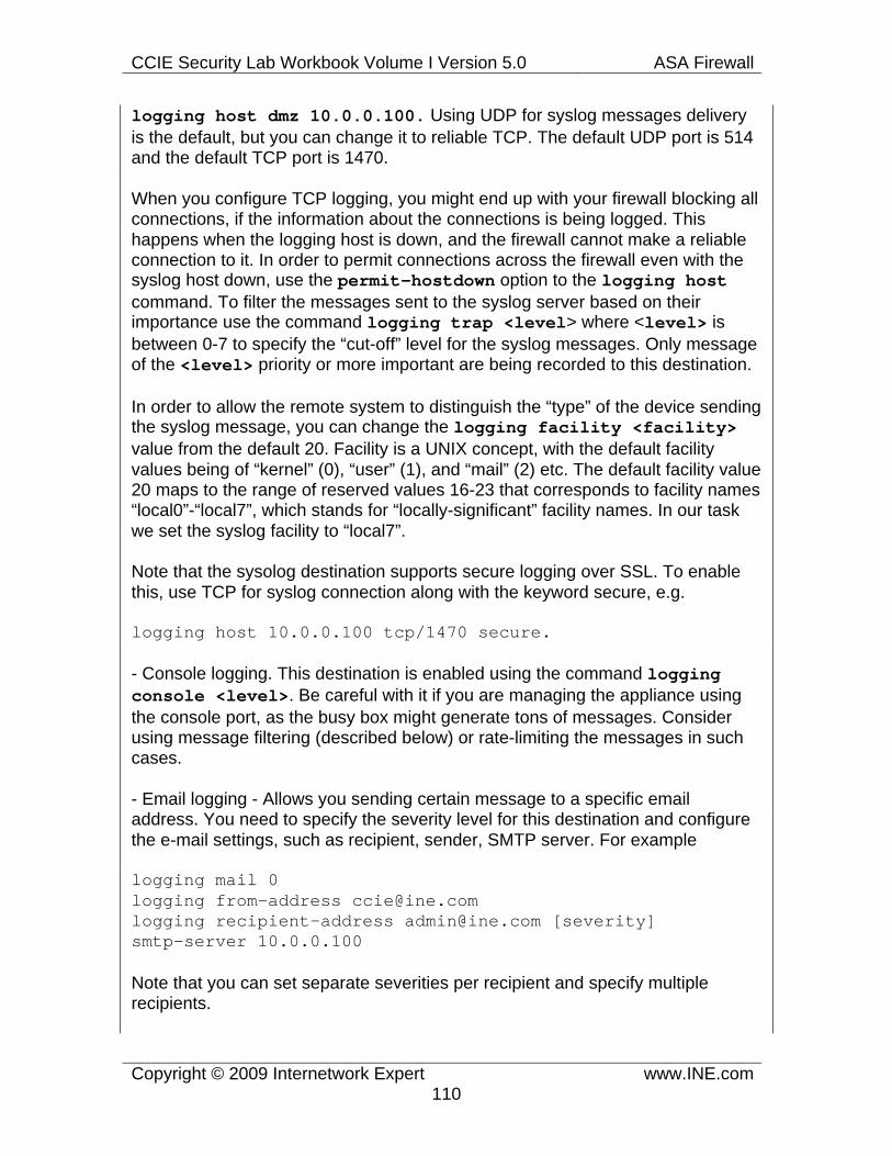
CCIE Security Lab Workbook Volume I Version 5.0 ASA Firewall
Copyright © 2009 Internetwork Expert www.INE.com110
logging host dmz 10.0.0.100. Using UDP for syslog messages delivery is the default, but you can change it to reliable TCP. The default UDP port is 514 and the default TCP port is 1470.
When you configure TCP logging, you might end up with your firewall blocking all connections, if the information about the connections is being logged. This happens when the logging host is down, and the firewall cannot make a reliable connection to it. In order to permit connections across the firewall even with the syslog host down, use the permit-hostdown option to the logging host command. To filter the messages sent to the syslog server based on their importance use the command logging trap <level> where <level> is between 0-7 to specify the “cut-off” level for the syslog messages. Only message of the <level> priority or more important are being recorded to this destination.
In order to allow the remote system to distinguish the “type” of the device sending the syslog message, you can change the logging facility <facility> value from the default 20. Facility is a UNIX concept, with the default facility values being of “kernel” (0), “user” (1), and “mail” (2) etc. The default facility value 20 maps to the range of reserved values 16-23 that corresponds to facility names “local0”-“local7”, which stands for “locally-significant” facility names. In our task we set the syslog facility to “local7”.
Note that the sysolog destination supports secure logging over SSL. To enable this, use TCP for syslog connection along with the keyword secure, e.g.
logging host 10.0.0.100 tcp/1470 secure.
- Console logging. This destination is enabled using the command logging console <level>. Be careful with it if you are managing the appliance using the console port, as the busy box might generate tons of messages. Consider using message filtering (described below) or rate-limiting the messages in such cases.
- Email logging - Allows you sending certain message to a specific email address. You need to specify the severity level for this destination and configure the e-mail settings, such as recipient, sender, SMTP server. For example
logging mail 0 logging from-address [email protected] logging recipient-address [email protected] [severity] smtp-server 10.0.0.100
Note that you can set separate severities per recipient and specify multiple recipients.

CCIE Security Lab Workbook Volume I Version 5.0 ASA Firewall
Copyright © 2009 Internetwork Expert www.INE.com111
- ASDM logging – stores and sends messages to the ASDM management console. Enabled using the command logging asdm <severity>. ASDM messages are stored in a separate buffer, with the size defined by using the command logging asdm-buffer-size <number_of_messages>.
- Logging to selected remote Telnet/SSH session (monitor logging). Use the command logging monitor <severity> to activate this destination. Note that the remote users need to issue the command terminal monitor to start receiving the logging messages.
- Logging to the memory buffer. Allows you saving syslog messages in the appliance’s memory, avoiding the hurdle of messages on the console screen. Activate this destination using the command logging buffered <level>. You can tune the buffer size using the command logging buffer-size <bytes>. To view the log buffer use the command show logging and to clear its contents use the command clear logging buffer. Note that the firewall will overwrite the memory buffer once it exhausts the memory allocated to it. You can configure the firewall to save the old contents to the flash memory every time the buffer wraps using the command logging flash-bufferwrap. You can also save the buffer to the flash memory at any time using the command logging savelog <filename>. The maximum amount fo flash memory available to buffer saves is set using the command logging flash-maximum-allocation <size_in_kilobytes>.
Alternatively, the contents of the memory buffer could be saved using a remote FTP server and the command logging ftp-bufferwrap. To define the remote FTP server parameters use the command logging ftp-server <server> <path> <username> <password>,e.g.
logging ftp-server 10.0.0.100 /var/logs admin cisco..
ASA1: logging timestamp logging buffer-size 65536 logging console alerts logging monitor critical logging buffered debugging logging trap informational logging facility 23 logging host dmz 10.0.0.100 ! logging ftp-bufferwrap logging ftp-server 10.0.0.100 / anonymous [email protected]! logging enable

CCIE Security Lab Workbook Volume I Version 5.0 ASA Firewall
Copyright © 2009 Internetwork Expert www.INE.com112
Verification
Note
Verify the current logging settings:
Rack1ASA1# show logging Syslog logging: enabled Facility: 23 Timestamp logging: enabled Standby logging: disabled Deny Conn when Queue Full: disabled Console logging: level alerts, 0 messages logged Monitor logging: level critical, 0 messages logged Buffer logging: level debugging, 7 messages logged Trap logging: level informational, facility 23, 6 messages logged Logging to dmz 10.0.0.100 History logging: disabled Device ID: disabled Mail logging: disabled ASDM logging: level informational, 12 messages logged
Note
Run a syslog application in the AAA/CA server and ensure it collects the logging messages.

CCIE Security Lab Workbook Volume I Version 5.0 ASA Firewall
Copyright © 2009 Internetwork Expert www.INE.com113
1.26 Filtering System Logs
• Ensure the message with the ID 103012 is never sent to any destination. • Limit the messages visible to the users on the console to VPN-related
errors or more severe information. • The syslog server should only receive messages with IDs in range
101002-105044.
Configuration
Note
Filtering system log message is important in situations when you are overwhelmed with the information. The ASA firewall provides you with the following ways to filter the logging messages:
- The default way, which is setting the severity for a particular destination.
- Class-based filtering, using the command logging class <class> <destination> <severity> e.g. logging class vpn console errors like used in our scenario. This setting would override any previous settings for this destination, for example if anything has been set using the command logging console debugging.
- Changing logging level for selected syslog Message-ID. If you know your message ID, you can fully disable it by using the command no logging message <message-ID> or change the logging level using the command logging message <message-ID> level <lvl>.
- Creating a logging list and applying it to the destination. The logging list is a re-usable combination of either message class/level or a range of message IDs. It is just more flexible way of applying the previous two methods. You define the logging list using the command logging list <name> {level <level> [class <message_class>] | <msg_start_id>[-<msg_end_id>]}. You may then apply the list to the particular destination using the command logging <destination> <list-name>.
In our scenario we use both the class-based filtering and create a custom message list.
ASA1: no logging message 103012 logging class vpn console errors

CCIE Security Lab Workbook Volume I Version 5.0 ASA Firewall
Copyright © 2009 Internetwork Expert www.INE.com114
logging list TEST message 101002-105044 ! logging trap TEST
Verification
Note
Use the show logging command to verify the current logging settings:
Rack1ASA1# show logging Syslog logging: enabled Facility: 23 Timestamp logging: enabled Standby logging: disabled Deny Conn when Queue Full: disabled Console logging: level alerts, class vpn, 0 messages logged Monitor logging: level critical, 0 messages logged Buffer logging: level debugging, 22 messages logged Trap logging: list TEST, facility 23, 9 messages logged Logging to dmz 10.0.0.100 History logging: disabled Device ID: disabled Mail logging: disabled ASDM logging: level informational, 19 messages logged
CCIE Security Lab Workbook Volume I Version 5.0 ASA Firewall
Copyright © 2009 Internetwork Expert www.INE.com115
1.27 SNMP Monitoring
• Configure SNMP settings as follows:
o Deny SNMP version 1 request. Use snmp-map for this task. o Send all SNMP traps to DMZ host 10.0.0.100. o Use SNMP server community to “CISCO”. o Set SNMP server location to “Reno,NV”.
• Ensure the VPN messages of critical or higher level are also delivered as SNMP traps.
Configuration
Note
The firewall appliance supports SNMP versions 1 and 2c, but not the newer version 3. Additionally, you can only poll the device via SNMP or configure the ASA to send SNMP traps, but you cannot configure the device via SNMP. To define a host allowed polling and receiving traps from the appliance, use the command
snmp-server host <iface> <IP> [trap|poll] [community <KEY>]
This statement permits the configured host to poll the device and receive SNMP traps. If you specify one of the keywords trap or poll, the device in limited to that function only. Specify the community string explicitly if it differs from the globally configured community set using the command snmp-server community <KEY>. The community value is used for authentication of SNMP messages and is a pre-shared secret on both the managed device and the management station.
In order to enable sending of SNMP traps, issue the command snmp-server enable-traps [all|<list_of_traps>]. If you don’t specify any arguments to this command, the default set of SNMP traps is enabled. Note the special type of syslog traps, which are used to convey the system log messages when you enable logging history in the global configuration mode. This allows logging of the syslog messages via SNMP traps. ƒ√ You can selectively deny certain SNMP version messages using the command snmp deny version. However, in this scenario we use the MPF inspection to block SNMP version 1 packets, by configuring a special snmp_map that denies SNMPv1 packets.

CCIE Security Lab Workbook Volume I Version 5.0 ASA Firewall
Copyright © 2009 Internetwork Expert www.INE.com116
Other SNMP commands, such as snmp-server location are intuitive, and define various informational parameters.
ASA1: ! ! Configure SNMP to allow the AAA/CA server to receive traps only ! snmp-server community CISCO snmp-server host dmz 10.0.0.100 trap snmp-server location Reno,NV snmp-server enable traps all
! ! Enable logging of critical messages via SNMP ! logging history critical
! ! Create snmp-map to deny SNMP version 1 ! snmp-map asa_snmp_map deny version 1 ! ! Apply the map to the global policy ! policy-map global_policy class inspection_default inspect snmp asa_snmp_map
Verification
Note
You may use the command show snmp-server statistics to notice the exchange of SNMP PDUs if you have real SNMP management station connected.

CCIE Security Lab Workbook Volume I Version 5.0 ASA Firewall
Copyright © 2009 Internetwork Expert www.INE.com117
1.28 DHCP Server
• Configure the ASA firewall to act as a DHCP server on the “Inside” interface.
• Use the IP address range “136.X.121.100-136.X.121.254”. • Assign the domain-name “ine.com” to the DHCP clients. • Lease the IP addresses for 30 minutes. • Verify by configuring R1 for DHCP address allocation on its Ethernet
interface.
Configuration
Note
The firewall appliance may function as DHCP Server, even in Transparent Firewall mode. As a server, the appliance could be configured to allocate IP addresses, usually on its “inside” interface. You can set the address range for clients using the command dhcpd address <Addr1>-<Addr2> <iface>. Other default DHCP options, such as DNS/WINS servers, domain name and lease duration could be set using the respective DHCP sub-commands. Do not forget to enable the DHCP server on the interface using the command dhcpd enable.
Note the interesting command dhcpd auto_config <iface>. If you have the mentioned interface <iface> configured for IP addressing via DHCP (the ASA configure its own IP via DHCP) then you can import the DNS/WINS/Domain settings from the DHCP client to the DHCP server in the ASA.
A few words on DHCP options. The firewall allows you setting any legal option value using the command dhcpd option. What you may need is option 3 (default gateway IP address) in transparent firewall mode. It allows you setting the default gateway to something different than the management IP address of the firewall. Another option, useful when you are dealing with Cisco IP Phones is option 150 (TFTP Server List) which you can set to the IP address of the Cisco Call Manager if needed.
Lastly, you may configure the firewall to work as DHCP relay. In this mode, as soon as the firewall receives a DHCP request on the interface configured for DHCP relaying, it sets the giaddr (gateway IP address) field in the DHCP packet to the IP of the relaying interface and forwards the request to the configured DHCP server. The commands to configure DHCP relay are dhcprelay server <IP> to define the actual DHCP server and dhcprelay enable <iface> to define the relaying interface. The command dhcprelay
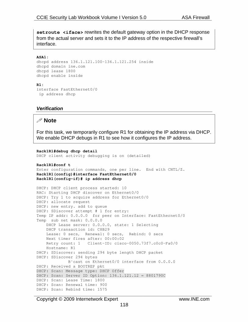
CCIE Security Lab Workbook Volume I Version 5.0 ASA Firewall
Copyright © 2009 Internetwork Expert www.INE.com118
setroute <iface> rewrites the default gateway option in the DHCP response from the actual server and sets it to the IP address of the respective firewall’s interface.
ASA1: dhcpd address 136.1.121.100-136.1.121.254 inside dhcpd domain ine.com dhcpd lease 1800 dhcpd enable inside
R1: interface FastEthernet0/0 ip address dhcp
Verification
Note
For this task, we temporarily configure R1 for obtaining the IP address via DHCP. We enable DHCP debugs in R1 to see how it configures the IP address.
Rack1R1#debug dhcp detail DHCP client activity debugging is on (detailed)
Rack1R1#conf t Enter configuration commands, one per line. End with CNTL/Z. Rack1R1(config)#interface FastEthernet0/0 Rack1R1(config-if)# ip address dhcp
DHCP: DHCP client process started: 10 RAC: Starting DHCP discover on Ethernet0/0 DHCP: Try 1 to acquire address for Ethernet0/0 DHCP: allocate request DHCP: new entry. add to queue DHCP: SDiscover attempt # 1 for entry: Temp IP addr: 0.0.0.0 for peer on Interface: FastEthernet0/0 Temp sub net mask: 0.0.0.0 DHCP Lease server: 0.0.0.0, state: 1 Selecting DHCP transaction id: C8B29 Lease: 0 secs, Renewal: 0 secs, Rebind: 0 secs Next timer fires after: 00:00:02 Retry count: 1 Client-ID: cisco-0050.73f7.c0c0-Fa0/0 Hostname: R1 DHCP: SDiscover: sending 294 byte length DHCP packet DHCP: SDiscover 294 bytes B'cast on Ethernet0/0 interface from 0.0.0.0 DHCP: Received a BOOTREP pkt DHCP: Scan: Message type: DHCP Offer DHCP: Scan: Server ID Option: 136.1.121.12 = 8801790C DHCP: Scan: Lease Time: 1800 DHCP: Scan: Renewal time: 900 DHCP: Scan: Rebind time: 1575

CCIE Security Lab Workbook Volume I Version 5.0 ASA Firewall
Copyright © 2009 Internetwork Expert www.INE.com119
DHCP: Scan: Subnet Address Option: 255.255.255.0 DHCP: Scan: Domain Name: internetworkexpert.com DHCP: Scan: Router Option: 136.1.121.12 DHCP: rcvd pkt source: 136.1.121.12, destination: 255.255.255.255 UDP sport: 43, dport: 44, length: 312 DHCP op: 2, htype: 1, hlen: 6, hops: 0 DHCP server identifier: 136.1.121.12 xid: C8B29, secs: 0, flags: 0 client: 0.0.0.0, your: 136.1.121.100 srvr: 0.0.0.0, gw: 0.0.0.0 options block length: 64 DHCP Offer Message Offered Address: 136.1.121.100 DHCP: Lease Seconds: 1800 Renewal secs: 900 Rebind secs: 1575 DHCP: Server ID Option: 136.1.121.12 DHCP: offer received from 136.1.121.12 DHCP: SRequest attempt # 1 for entry: Temp IP addr: 136.1.121.100 for peer on Interface: FastEthernet0/0 Temp sub net mask: 255.255.255.0 DHCP Lease server: 136.1.121.12, state: 2 Requesting DHCP transaction id: C8B29 Lease: 1800 secs, Renewal: 0 secs, Rebind: 0 secs Next timer fires after: 00:00:01 Retry count: 1 CInterface FastEthernet0/0 assigned DHCP address 136.1.121.100, mask 255.255.255.0 lient-ID: cisco-0050.73f7.c0c0-Fa0/0 Hostname: R1 DHCP: SRequest- Server ID option: 136.1.121.12 DHCP: SRequest- Requested IP addr option: 136.1.121.100 DHCP: SRequest placed lease len option: 1800 DHCP: SRequest: 312 bytes DHCP: SRequest: 312 bytes B'cast on FastEthernet0/0 interface from 0.0.0.0 DHCP: Received a BOOTREP pkt DHCP: Scan: Message type: DHCP Ack DHCP: Scan: Server ID Option: 136.1.121.12 = 8801790C DHCP: Scan: Lease Time: 1800 DHCP: Scan: Renewal time: 900 DHCP: Scan: Rebind time: 1575 DHCP: Scan: Host Name: R1.inet.com DHCP: Scan: Subnet Address Option: 255.255.255.0 DHCP: Scan: Domain Name: ine.com DHCP: Scan: Router Option: 136.1.121.12 DHCP: rcvd pkt source: 136.1.121.12, destination: 255.255.255.255 UDP sport: 43, dport: 44, length: 339 DHCP op: 2, htype: 1, hlen: 6, hops: 0 DHCP server identifier: 136.1.121.12 xid: C8B29, secs: 0, flags: 0 client: 0.0.0.0, your: 136.1.121.100 srvr: 0.0.0.0, gw: 0.0.0.0 options block length: 91 DHCP Ack Message DHCP: Lease Seconds: 1800 Renewal secs: 900 Rebind secs: 1575 DHCP: Server ID Option: 136.1.121.12 DHCP Host Name Option: R1.ine.com DHCP Client Pooling: ***Allocated IP address: 136.1.121.100 Allocated IP address = 136.1.121.100 255.255.255.0

CCIE Security Lab Workbook Volume I Version 5.0 ASA Firewall
Copyright © 2009 Internetwork Expert www.INE.com120
1.29 HTTP Traffic Inspection
• Ensure that the AAA/CA server is accessible from the outside using the IP address “136.X.122.100”.
• The ASA should spoof the HTTP server headers to pretend that it is “Apache/2.2.0 (Unix)”.
• Additionally, the firewall should reset the TCP connection upon any HTTP protocol violations for extra security.
• For the HTTP connections from the inside, restrict the number of half-open connections to 100 and the total number of connections to the HTTP server to 200.
• Since DoS attacks are more expected from the outside, ensure the firewall allows no more than 50 embryonic connections from the outside and limit the total number of outside connections to 100.
Configuration
Note
The purpose of Modular Policy Framework is to allow creating flexible traffic inspection rules. Traffic inspection is the core of the stateful firewall, as it accomplishes the following main purposes:
1) Inspects protocol commands and dynamically modify firewall rules to permit secondary information channels, like with H.323 and FTP 2) Perform deep traffic inspection to detect protocol violations, anomalies and attacks. 3) Dynamically modify packet contents to remove potential threats or hide some sensitive information.
MPF replaced the legacy fixup traffic inspection command with totally new configuration concepts. MPF (Modular Policy Framework) configuration is similar to MQC (Modular QoS CLI) configuration on IOS router. Starting with recent IOS releases you may find many similarities between the IOS zone based firewall and the ASA MPF configuration.
In order to inspect traffic in the ASA firewall you should perform the following basic steps:
1) Define Layer 3/Layer 4 classification criteria. For example, if you want to inspect HTTP traffic to a particular server, you may define an access-list to match this traffic e.g. access-list HTTP_TRAFFIC_ACL permit tcp any host 10.0.0.100 eq 80 and then create new L3/L4 class-map that matches the traffic flow:

CCIE Security Lab Workbook Volume I Version 5.0 ASA Firewall
Copyright © 2009 Internetwork Expert www.INE.com121
class-map HTTP_TRAFFIC_CMAP match access-list HTTP_TRAFFIC_ACL
This is very similar to MQC configuration in IOS routers – class-maps are used for traffic classification based on L3/L4 criteria. As usual, you may create match-any or match-all class-maps, with the first type matching any of the statements in the class-map, while the second requiring all statements to be matched. In addition to using ACLs, you can match traffic based on DSCP/Precedence, port numbers as well, though using the ACLs is more flexible. In addition, the ASA firewall allows using some unique classification criteria, such as matching VPN traffic flows.
2) Define a policy-map that associates certain actions with L3/L4 class-maps. For example, here is a policy that inspects HTTP traffic:
policy-map INSPECT_HTTP_PMAP class HTTP_TRAFFIC_CMAP inspect http
This will apply HTTP inspection engine to the traffic matching the L3/L4 class map. In addition to inspection, another most common setting is the command set connection which allows changing various TCP session parameters. Most notably, you can change the maximum number of connections and the maximum number of half-open (embryonic) connections for the particular traffic class. This is much more flexible that using the static command.
3) Apply the policy map to an interface or globally. When you apply the service policy to an interface using the command service-policy <POLICY> interface <iface> all ingress or egress traffic on the interface <iface> is inspected according to the policy settings. When you apply the policy-map globally using the command service-policy <POLICY> global it applies to all inbound traffic flows on all interfaces.
Note that there is always a global policy defined, either user-specified or the default. If you have both the global and interface policies applied, the interface policy takes precedence for the same feature. For example, if the interface-level policy inspects HTTP and the global policy inspects FTP than the effect is combined. However, if both the interface and global policy inspects the same protocol (with potentially different settings) than the interface-level policy-map takes precedence.
The default inspection policy uses special match statement match default-inspection-traffic, which allows matching a bunch of default protocols at the same time. The respective class has a group of inspect statements

CCIE Security Lab Workbook Volume I Version 5.0 ASA Firewall
Copyright © 2009 Internetwork Expert www.INE.com122
associated in the default global policy-map. This is needed to replicate the default behavior of the old fixup commands.
The next question is – what if we would like to tune the inspection engine parameters, instead of simply relaying on the default values? For example, we would like to tune HTTP and FTP inspection. To accomplish this, the firewall supports the concepts of inspection class-maps and policy-maps. Defined using the syntax class-map type inspect <protocol> and policy-map type inspect <protocol> they are designed to be used together. If we want to create a customer HTTP inspection rule, we would use the following syntax:
policy-map type inspect http HTTP_INSPECT parameters protocol-violation action reset
Later, this customer inspection policy map is bound to the inspect statement under the L3/L4 class in the regular policy-map:
policy-map INSPECT_HTTP_PMAP class HTTP_TRAFFIC_CMAP inspect http HTTP_INSPECT
allowing for fine-tuning of HTTP inspection engine. Every type of inspect policy map (HTTP, ESMTP, FTP, DNS and so on) has its own set of unique parameters and options, which are fully described in the firewall documentation. Some advanced inspection settings might require protocol-specific classifications. For example, you might want to set various HTTP inspection options only for sites matching certain URLs. To accomplish this, we create a special HTTP inspect class-map that matches the URIs against certain regex and then we use this class in the HTTP inspect policy-map and associate and action.
regex CISCO "www\.cisco\.com/.*"
class-map type inspect http URI_CISCO match request uri regex CISCO
policy-map type inspect http HTTP_POLICY class URI_CISCO log
You cannot use regular L3/L4 class-maps with the inspect type policy-map. Remember that inspection policy-maps have no effect until they are associated with the inspect command in a normal policy-map.
As for our scenario, it is relatively straight-forward. We classify traffic going to the

CCIE Security Lab Workbook Volume I Version 5.0 ASA Firewall
Copyright © 2009 Internetwork Expert www.INE.com123
WWW server from the inside and outside directions, by using two L3/L4 class-maps. Both class-maps match access-lists, but one of them uses the translated IP address of the WWW server (for the outside policy).
Then we create a special HTTP inspection policy-map that is used to tweak the HTTP inspection settings. After this, the final step is creating two normal policy-maps, for the inside and outside interfaces. The inside-interface policy-map matches the class for “inside to the server” traffic and the outside interface policy-map matches the traffic from the “outside to the server”. Both policy-maps apply the HTTP inspection policy to the matched traffic. In addition to that, the connection options are set to accomplish the goal of limiting the number of half-open and open sessions.
ASA1: ! ! Static mapping ! static (dmz,outside) 136.1.122.100 10.0.0.100 netmask 255.255.255.255
! ! Define & Apply Access-Lists ! access-list OUTSIDE_IN permit tcp any host 136.1.122.100 eq www access-group OUTSIDE_IN in interface outside
! ! Clasify traffic from inside to the WWW server ! access-list HTTP_FROM_INSIDE permit tcp 136.1.121.0 255.255.255.0 host 10.0.0.100 eq www
! ! Classify traffic from outside to the WWW server ! access-list HTTP_FROM_OUTSIDE permit tcp 136.1.122.0 255.255.255.0 host 136.1.122.100 eq www
! ! Define L3/L4 class-maps ! class-map HTTP_FROM_INSIDE match access-list HTTP_FROM_INSIDE
class-map HTTP_FROM_OUTSIDE match access-list HTTP_FROM_OUTSIDE
! ! Define HTTP inspection policy ! policy-map type inspect http HTTP_INSPECT parameters spoof-server "Apache/2.2.0 (Unix)"

CCIE Security Lab Workbook Volume I Version 5.0 ASA Firewall
Copyright © 2009 Internetwork Expert www.INE.com124
protocol-violation action reset
! ! Create policy maps ! policy-map OUTSIDE class HTTP_FROM_OUTSIDE inspect http HTTP_INSPECT set connection conn-max 100 embryonic-conn-max 50
policy-map INSIDE class HTTP_FROM_INSIDE inspect http HTTP_INSPECT set connection conn-max 200 embryonic-conn-max 100
! ! Apply the policies ! service-policy OUTSIDE interface outside service-policy INSIDE interface inside
Verification
Note
The verification procedure is simulation based. You connect to the HTTP server and issue a GET request, observing the HTTP headers. Note that in both cases the server is masqueraded as Apache, even though it is ISS.
Rack1R1#telnet 10.0.0.100 80 Trying 10.0.0.100, 80 ... Open GET / HTTP/1.1
HTTP/1.1 400 Bad Request Server:Apache/2.2.0 (Unix) Date: Wed, 10 Jan 2007 11:58:13 GMT Connection: close Content-Length: 4009 Content-Type: text/html <!DOCTYPE HTML PUBLIC "-//W3C//DTD HTML 3.2 Final//EN">
Rack1R2#telnet 136.1.122.100 80 Trying 136.1.122.100, 80 ... Open GET / HTTP/1.1
HTTP/1.1 400 Bad Request Server:Apache/2.2.0 (Unix) Date: Wed, 10 Jan 2007 11:59:27 GMT Connection: close Content-Length: 4009 Content-Type: text/html <!DOCTYPE HTML PUBLIC "-//W3C//DTD HTML 3.2 Final//EN">
CCIE Security Lab Workbook Volume I Version 5.0 ASA Firewall
Copyright © 2009 Internetwork Expert www.INE.com125
1.30 FTP Traffic Inspection
• Allow the hosts from outside to access the FTP server at the IP 10.0.0.100 using the outside IP address 136.X.122.100.
• Disallow the use of commands “RMD”, “SITE” and “DELETE”. • Deny the download of the IOS images files with names that start with
“c26”, “c36” and “c28”. • In order to prevent hackers from using the known exploits, mask the FTP
server banner and the system information reply. • The restrictions should only apply to the users accessing from the outside.
Configuration
Note
This task further illustrates the use of inspect class-maps and policy-maps. We are required to deny certain FTP commands and prevent certain files from downloading. Usually, when you see something asking about name-based policy, you mostly likely need to configure regular expressions (regexps) in the firewall. Explaining regula expressions in depth is outside the score of this book. However, in short, regular expressions are normal strings with special characters used to create “wildcard” matching. Most common patterns are outlined below:
^begin – this pattern will match any string that starts with “begin”. Here “^” means “start of the string”. term$ – this pattern matches any string that ends with “term”, thus “$” means “end of the string”. Using “^” or “$” is also called “anchoring”. When you use the pattern ^test$ it will match only the whole word “test”. [tT]est – matches both “test” and “Test”, thus “[]” means “range of characters”. You can use the dash sign to define consecutive ranges, e.g. [1-9] means “[123456789]” and “[a-z]” covers the whole alphabet. It is common to use the “[]” to match the letter of different case. test.123 – pay attention to the “dot” – it means “any character”, thus the pattern will match “test0123”, “testA123”, “testX123” and so on. ab* - matches “a”, “ab”, “abb”, “abbbb” and so on. The asterisk symbol mean that the previous character could be repeated any number of times including zero. ab+ - matches “ab”, “abb”, “abbb” – similar to the asterisk, but means repeating at least one time. It is common to see “*“ and “+” used with “.”, for example “.*” would match any string, even empty. ab? – matches “ab” and “a”. The question mark means the previous character could be repeated one or zero times.
In the ASA firewall, you define regular expressions using the regex command.

CCIE Security Lab Workbook Volume I Version 5.0 ASA Firewall
Copyright © 2009 Internetwork Expert www.INE.com126
Every regex has a name which could be used in the inspect class-maps that support matching on regex. You can use the special regex class-maps to group regular expressions using AND/OR logic. For example, the following class-map would match if the string matches ANY of the containing regular expressions:
class-map type regex match-any OR_LOGIC match REGEX1 match REGEX2
On the contrary, the match-all class-map will require the string to match ALL of the containing regular expressions. In our scenario, we create three regular expressions and group them into the regex class-map, although you could simplify the configuration and use just one regex, such as “^c[23][68].*”
Next note that the FTP inspection policy-maps allows matching filenames directly, without creating any special inspection class-maps. The syntax is match filename regex class <CLASS> directly within the inspect policy map. The same inspection policy-map allows setting the FTP inspection options directly. However, note the use of the FTP inspection class-map to match FTP command:
class-map type inspect ftp match-all DENIED_COMMANDS match request-command site dele rmd
you need to know how FTP protocol operates in order to understand which commands should be banned under different conditions. Read the RFC on FTP protocol to get more information.
For both the denied names and denied commands we instruct the inspection engine to reset the active FTP connection. This finishes the configuration of the FTP inspection policy map. Next we proceed to creation of the L3/L4 policy map that matches FTP traffic. This class is matched using the normal policy map, and the custom FTP inspection policy-map that we created is applied here. Note that you need to use the command inspect ftp strict in order to apply the FTP inspection policy-map. Finally, the regular policy map is applied to the outside interface.
ASA1: ! ! Regexps ! regex REG_26XX "^c26.*" regex REG_36XX "^c36.*" regex REG_28XX "^c28.*"
! ! Class-map to group regexps

CCIE Security Lab Workbook Volume I Version 5.0 ASA Firewall
Copyright © 2009 Internetwork Expert www.INE.com127
! class-map type regex match-any DENIED_FILES match regex REG_26XX match regex REG_28XX match regex REG_36XX
! ! Class-map to group together the denied commands ! class-map type inspect ftp match-all DENIED_COMMANDS match request-command site dele rmd
! ! FTP inspection policy. Note the obfuscation options ! policy-map type inspect ftp FTP_INSPECT parameters mask-banner mask-syst-reply match filename regex class DENIED_FILES reset class DENIED_COMMANDS reset
! ! Class to match FTP port (L3/L4) ! class-map FTP match port tcp eq 21
! ! Policy map to apply to outside interface ! policy-map OUTSIDE class FTP inspect ftp strict FTP_INSPECT
! ! Apply policy to outside interface ! service-policy OUTSIDE interface outside
! ! Static Mapping to simplify routing ! static (dmz,outside) 136.1.122.100 10.0.0.100
! ! Outside ACL to permit FTP traffic ! access-list OUTSIDE_IN permit tcp any host 136.1.122.100 eq 21 access-group OUTSIDE_IN in interface outside
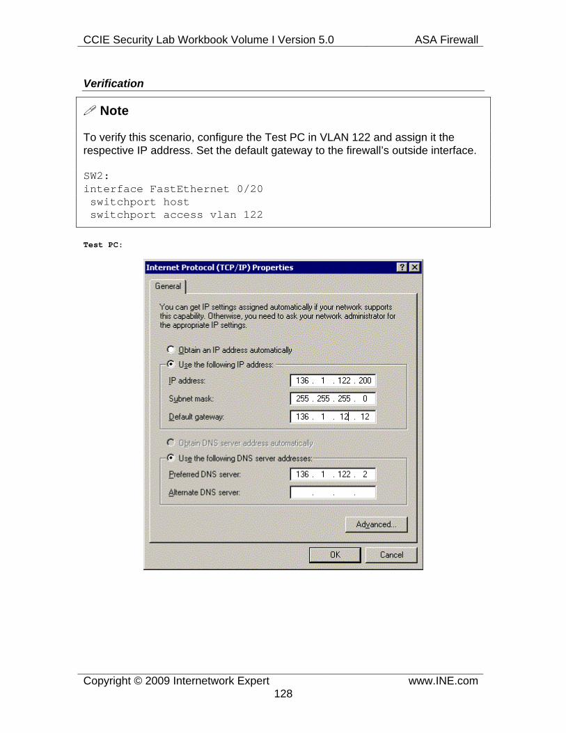
CCIE Security Lab Workbook Volume I Version 5.0 ASA Firewall
Copyright © 2009 Internetwork Expert www.INE.com128
Verification
Note
To verify this scenario, configure the Test PC in VLAN 122 and assign it the respective IP address. Set the default gateway to the firewall’s outside interface.
SW2: interface FastEthernet 0/20 switchport host switchport access vlan 122
Test PC:
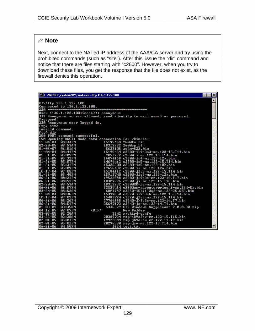
CCIE Security Lab Workbook Volume I Version 5.0 ASA Firewall
Copyright © 2009 Internetwork Expert www.INE.com129
Note
Next, connect to the NATed IP address of the AAA/CA server and try using the prohibited commands (such as “site”). After this, issue the “dir” command and notice that there are files starting with “c2600”. However, when you try to download these files, you get the response that the file does not exist, as the firewall denies this operation.

CCIE Security Lab Workbook Volume I Version 5.0 ASA Firewall
Copyright © 2009 Internetwork Expert www.INE.com130

CCIE Security Lab Workbook Volume I Version 5.0 ASA Firewall
Copyright © 2009 Internetwork Expert www.INE.com131
1.31 SMTP Traffic Inspection
• The outside users should be able to send mail using the server at the IP address 136.X.122.100 mapped to the DMZ IP 10.0.0.100.
• Configure the ASA to reject email sent from the e-mail addresses containing any of the strings “cyberspam.org” or “nullroute.com”.
• The firewall should perform SMTP banner obfuscation in order to prevent the SMTP server identification.
• The firewall should only accept emails addresses to domain “cisco.com”. • Reject the emails that have more than 3 invalid recipients. • In order to protect against TCP SYN flooding, limit the number of half-
open connections to 50 and the maximum number of connections to 100.
Configuration
Note
This example is practically the same as the two previous, just this time configurations apply to the SMTP inspection policy map. For detailed information on all SMTP inspection options, refer to the ASA configuration reference guide.
In this task we configure a regex to match senders email addresses. This regex is later used in the SMTP inspection policy map. The same inspection policy map is configured for SMTP banner obfuscation in addition to allowing email relaying only for domain cisco.com.
Finally, we create an access-list and L3/L4 class-map that matches SMTP traffic to the server. Lastly, a regular policy-map is created, matching the L3/L4 class and setting various TCP connection options. Additionally, ESMTP inspection is configured along with the custom inspection policy map.
ASA1: ! ! Static mapping and access-list to permit SMTP ! static (dmz,outside) 136.1.122.100 10.0.0.100 access-list OUTSIDE_IN permit tcp any host 136.1.122.100 eq 25 access-group OUTSIDE_IN in interface outside
! ! Regexps to match potentially unwanted content ! regex UNWANTED “(cyberspam.org|nullroute.com)”
! ! SMTP Inspection Policy ! policy-map type inspect esmtp SMTP_INSPECT

CCIE Security Lab Workbook Volume I Version 5.0 ASA Firewall
Copyright © 2009 Internetwork Expert www.INE.com132
parameters mask-banner mail-relay cisco.com action drop-connection exit match invalid-recipients count gt 3 reset match sender-address regex UNWANTED reset
! ! Access-list and L3/L4 class-map ! access-list SMTP_SERVER permit tcp any host 136.1.122.100 eq 25 class-map SMTP_SERVER match access-list SMTP_SERVER
! ! Create and apply outside policy-map ! policy-map OUTSIDE class SMTP_SERVER set connection conn-max 100 set connection embryonic-conn-max 50 inspect esmtp SMTP_INSPECT ! service-policy OUTSIDE interface outside
Verification
Note
This time, check that the policy map is applied to the interface (note the connection limit settings) and then try connecting to the SMTP server from R2. Note that the banner message is fully hidden, disallowing us to learn any information about the server software.
Note that the ASA rejects any SMTP commands sent over telnet connection as it interprets them incorrectly formatted (not per the RFC standards). Most SMTP servers accept SMTP sessions simulated over telnet, but the firewall checks are very strict on this.
Rack1ASA1(config)# show service-policy interface outside
Interface outside: Service-policy: OUTSIDE Class-map: SMTP_SERVER Set connection policy: conn-max 100 embryonic-conn-max 50 current embryonic conns 0, current conns 0, drop 0 Inspect: esmtp SMTP_INSPECT, packet 0, drop 0, reset-drop 0
Rack1R2#telnet 136.1.122.100 25 Trying 136.1.122.100, 25 ... Open

CCIE Security Lab Workbook Volume I Version 5.0 ASA Firewall
Copyright © 2009 Internetwork Expert www.INE.com133
220 *********************************************************************** ********************************** EHLO 500 5.3.3 Unrecognized command EHLO 250-IESERVER1 Hello [136.1.122.2] 250-AUTH GSSAPI NTLM LOGIN 250-AUTH=LOGIN 250-TURN 250-ATRN 250-SIZE 2097152 250-ETRN 250-PIPELINING 250-DSN 250-ENHANCEDSTATUSCODES 250-8bitmime 250-BINARYMIME 250-CHUNKING 250-VRFY 250 OK

CCIE Security Lab Workbook Volume I Version 5.0 ASA Firewall
Copyright © 2009 Internetwork Expert www.INE.com134
1.32 TCP Inspection
• Enforce additional security checks for TCP connections established across the firewall.
o Ensure the firewall checks retransmitted TCP packets. o The firewall should also validate TCP checksums. o Additionally, clear all reserved bits in TCP headers.
• The policy should apply all telnet connections crossing the firewall appliance.
• Limit the concurrent number of open Telnet session to 3 per user.
Configuration
Note
TCP carries most of the user traffic, and thus TCP inspection and security is top priority for the firewall. The appliance allows setting well-know TCP connection options such as:
1) Total number of open connections per MPF L3/L4 class (e.g. host, group of hosts, subnet etc) using the command set connection conn-max N 2) Total number of embryonic (aka half-open or incomplete) sessions per MPF L3/L4 class to prevent the well-known class of TCP SYN-flooding attacks. This feature supersedes the legacy static command TCP parameters. The syntax is set connection embryonic-conn-max N under the class-map assigned to a policy-map. 3) TCP Initial Sequence Number (ISN) randomization to prevent connection hijaaking or packet injection attacks. Use the command set random-sequence-number {enable|disable} to switch this feature for the hosts matched by the particular class-map.
The firewall also allows settings the connection limits on per-host (individual) basic. For example, if you configure set connection per-client max N command under a class, the limit will apply to every single host matched by this class-map and not to the aggregated number of connections. Of course, you an also limit the embryonic connections on per-client basis using the command set connection per-client-embryonic-max N.
In addition to these features, the ASA firewall allows you tuning various aspects of TCP connection normalization. The firewall applies number of security checks and modifications to the TCP connections in order to prevent potential attacks. You can modify some TCP normalization settings using the special tcp-map

CCIE Security Lab Workbook Volume I Version 5.0 ASA Firewall
Copyright © 2009 Internetwork Expert www.INE.com135
applied under L3/L4 class-map using the command set connection advanced-options like follows:
tcp-map TCP_MAP window-variation drop
access-list SSH permit tcp any any eq 22
class-map SSH match access-list SSH
policy-map TEST class SSH set connection advanced-options TCP_MAP
You may find the detailed description of all configurable TCP normalization parameters in the Firewall Configuration guide. Naturally, for better understanding of TCP normalization, you need to know TCP working internals (such as the format of TCP header, TCP flow control and TCP flags).
Note that when you apply TCP inspection/normalization features per interface, they affect both ingress and egress traffic. When the TCP features are applied using the global policy map, the affect ingress traffic on all interfaces.
ASA1: ! ! Define the TCP Map first ! tcp-map TCP check-retransmission checksum-verification reserved-bits clear
! ! Class-Map that matches Telnet Traffic ! class-map TELNET match port tcp eq 23
! ! Enforce the TCP normalization/connection settings ! policy-map global_policy class TELNET set connection per-client-max 3 set connection advanced-options TCP

CCIE Security Lab Workbook Volume I Version 5.0 ASA Firewall
Copyright © 2009 Internetwork Expert www.INE.com136
Verification
Note
Check the global service policy settings using the show command:
Rack1ASA1(config)# show service-policy global
Global policy: Service-policy: global_policy Class-map: inspection_default Inspect: dns preset_dns_map, packet 0, drop 0, reset-drop 0 Inspect: ftp, packet 0, drop 0, reset-drop 0 Inspect: h323 h225 _default_h323_map, packet 0, drop 0, reset-drop 0 Inspect: h323 ras _default_h323_map, packet 0, drop 0, reset-drop 0 Inspect: rsh, packet 0, drop 0, reset-drop 0 Inspect: rtsp, packet 0, drop 0, reset-drop 0 Inspect: sqlnet, packet 0, drop 0, reset-drop 0 Inspect: skinny, packet 0, drop 0, reset-drop 0 Inspect: sunrpc, packet 0, drop 0, reset-drop 0 Inspect: xdmcp, packet 0, drop 0, reset-drop 0 Inspect: sip, packet 0, drop 0, reset-drop 0 Inspect: netbios, packet 0, drop 0, reset-drop 0 Inspect: tftp, packet 0, drop 0, reset-drop 0 Inspect: icmp, packet 10, drop 0, reset-drop 0 Class-map: TELNET Set connection policy: Set connection advanced-options: TCP Retransmission drops: 0 TCP checksum drops : 0 Exceeded MSS drops : 0 SYN with data drops: 0 Out-of-order packets: 0 No buffer drops : 0 Reserved bit cleared: 0 Reserved bit drops : 0 IP TTL modified : 0 Urgent flag cleared: 0 Window varied resets: 0 TCP-options: Selective ACK cleared: 0 Timestamp cleared : 0 Window scale cleared : 0 Other options cleared: 0 Other options drops: 0

CCIE Security Lab Workbook Volume I Version 5.0 ASA Firewall
Copyright © 2009 Internetwork Expert www.INE.com137
1.33 Management Traffic Inspection
• There is a RADIUS server with the IP address 10.0.0.100 on the DMZ interface.
• The server expects the firewall to authenticate itself using the password value of “CISCO”.
• The firewall should inspect RADIUS accounting packets going to the IETF default RADIUS ports.
• Validate the RADIUS attribute number 26 and send accounting responses. • Apply the inspection rule globally.
Configuration
Note
The ASA firewall supports inspection for traffic originated to/from the firewall itself. Currently, the only protocol supported is RADIUS, with the purpose of validating firewall-to-server communications. There should be probably more protocols supported in the future.
When you configure management traffic inspection, you should create special type of class-map (type management) matching the respective management plane traffic. Note that this map is equivalent to L3/L4 class-map, not the special inspection map used with other protocols. Therefore, you assign this map to the normal policy maps applied globally or per-interface.
The firewall supports special type of policy-map of type radius-accountingthat is used to set the RADIUS protocol inspection parameters. This is the policy-map that you use as the parameter to inspect radius-accounting command. Under the radius-accounting inspection policy map you can set various supported inspection options. However, the main thing to set here is the IP address and the shared secret of the RADIUS server.
When you’re done configuring the RADIUS inspection policy map, you may apply it under a class in the global or per-interface policy-map. Note that this class will only match traffic terminated on the firewall itself, and will not affect inspection of the through traffic.
ASA1: ! ! Configure AAA server ! aaa-server RADIUS protocol radius aaa-server RADIUS (dmz) host 10.0.0.100 CISCO ! ! Configure management class-map to match RADIUS ACC packets

CCIE Security Lab Workbook Volume I Version 5.0 ASA Firewall
Copyright © 2009 Internetwork Expert www.INE.com138
! class-map type management RADIUS match port udp eqradius-acct ! ! RADIUS inspection policy ! policy-map type inspect radius-accounting RADIUS_INSPECT parameters send response validate-attribute 26 host 10.0.0.100 key CISCO ! policy-map global_policy class RADIUS inspect radius-accounting RADIUS_INSPECT
Verification
Note
Using the show command, verify that the policy has been applied:
Rack1ASA1(config)# show service-policy global
Global policy: Service-policy: global_policy Class-map: inspection_default Inspect: dns preset_dns_map, packet 0, drop 0, reset-drop 0 Inspect: ftp, packet 0, drop 0, reset-drop 0 Inspect: h323 h225 _default_h323_map, packet 0, drop 0, reset-drop 0 Inspect: h323 ras _default_h323_map, packet 0, drop 0, reset-drop 0 Inspect: rsh, packet 0, drop 0, reset-drop 0 Inspect: rtsp, packet 0, drop 0, reset-drop 0 Inspect: esmtp _default_esmtp_map, packet 0, drop 0, reset-drop 0 Inspect: sqlnet, packet 0, drop 0, reset-drop 0 Inspect: skinny, packet 0, drop 0, reset-drop 0 Inspect: sunrpc, packet 0, drop 0, reset-drop 0 Inspect: xdmcp, packet 0, drop 0, reset-drop 0 Inspect: sip, packet 0, drop 0, reset-drop 0 Inspect: netbios, packet 0, drop 0, reset-drop 0 Inspect: tftp, packet 0, drop 0, reset-drop 0 Class-map: RADIUS Inspect: radius-accounting RADIUS_INSPECT, packet 0

CCIE Security Lab Workbook Volume I Version 5.0 ASA Firewall
Copyright © 2009 Internetwork Expert www.INE.com139
1.34 ICMP Traffic Inspection
• Ensure that R1’s inside IP address 136.X.121.1 translates to the IP 136.X.122.1 on the outside.
• Ensure R1’s Loopback0 is advertised into RIP and reachable to R2. • Configure the firewall to allow the UNIX-style traceroute operation from
the outside. • When someone traces off R2 to R1’s Loopback0 interface he should not
see the inside IP address of R2 in reply packets. • Additionally, users from the inside should be able to ping outside without
an explicit permit entry in the outside ingress ACL.
Configuration
Note
Up until version 7.x the PIX code did not support ICMP packets inspection. Thus, you always needed to create access-list exceptions for returning ICMP traffic in order to permit the inside users to ping the outside destinations. Additionally, you need to create exceptions for ICMP error messages that were needed for commands such as traceroute and special processes such as pMTUD.
With the recent ASA code, you may inspect ICMP traffic in stateful manner, to allow the firewall opening dynamic pinholes for returning traffic. Thus, instead of explicitly permitting ICMP echo-reply packets in the firewall, you may just inspect ICMP packets going from inside to outside and get the same result. This also enforces more strict security, as the pinholes are opened only for the duration of the ICMP “session”.
As for ICMP error inspection, it serves a special purpose – replacing IP addresses/Ports embedded in the ICMP error messages (such as port unreachable, time exceeded and so on). This feature is best explained with the traceroute command. As we know, the traceroute send probe packets with increasing TTL values, expecting ICMP time-exceeded or ICMP port unreachable in response. The returning ICMP error messages contain the original IP addresses of the hosts discarding the original probes. Now imagine that the firewall performs address translation for inside hosts and you initiate a traceroute from the outside towards the translated IP addresses. As the probes will reach the inside IP addresses, the returning ICMP error messages will reveal the actual inside addresses of the hosts being traced. To prevent this information leaking, enable the ICMP error inspection, which will modify the IP addresses carried inside the error messages to match the translation rules.
In this scenario, we make sure that R1’s inside IP address could not be revealed

CCIE Security Lab Workbook Volume I Version 5.0 ASA Firewall
Copyright © 2009 Internetwork Expert www.INE.com140
by tracing from the outside. Additionally, the configuration permits pinging from the inside to the outside without explicitly permitting the returning traffic.
ASA1: clear configure nat clear configure static clear configure global clear configure access-list ! ! Static mapping ! static (inside,outside) 136.1.122.1 136.1.121.1
! ! Access-list to permit inboud traceroute ! access-list OUTSIDE_IN permit udp any any access-group OUTSIDE_IN in interface outside
! ! Apply ICMP inspection ! policy-map global_policy class inspection_default inspect icmp error inspect icmp
Verification
Note
Try pinging before and after you applied the ICMP inspection:
Before:
Rack1R1#ping 136.1.122.2
Type escape sequence to abort. Sending 5, 100-byte ICMP Echos to 136.1.122.2, timeout is 2 seconds: ..... Success rate is 0 percent (0/5) Rack1R1#
After:
Rack1R1#ping 136.1.122.2
Type escape sequence to abort. Sending 5, 100-byte ICMP Echos to 136.1.122.2, timeout is 2 seconds: !!!!! Success rate is 100 percent (5/5), round-trip min/avg/max = 100/158/176 ms

CCIE Security Lab Workbook Volume I Version 5.0 ASA Firewall
Copyright © 2009 Internetwork Expert www.INE.com141
Rack1R1#
Note
Next, issue the traceroute command on R2, tracing to the IP address of R1. The response should come from the FastEthernet interface of R1, and be translated to the outside IP. However, the ICMP error inspection hides the real IP address of R1:
Rack1R2#traceroute 150.1.1.1
Type escape sequence to abort. Tracing the route to 150.1.1.1
1 136.1.121.1 4 msec * 0 msec
Note
The IP address of the ASA firewall does not show up in the traceroute output.

CCIE Security Lab Workbook Volume I Version 5.0 ASA Firewall
Copyright © 2009 Internetwork Expert www.INE.com142
1.35 Threat Detection
• Enable basic threat detection on the firewall. • Set additional monitoring intervals for ACL drop event so that a message
is generated every time there are more than 10000 drops per two hours or more than 1000 drops per 10 seconds.
• Enable advanced scanning attack detection and automatic shunning of the attackers.
• Configure the firewall to shun the attackers for 10 minutes but never clear any connections originated from the 10.0.0.100 host.
Configuration
Note
Threat detection is the new ASA v8.x code feature. It allows detecting network by collecting the drop events occurring in the firewall and calculating their rates (speed). The firewall monitors certain events, such as ACL packet drops, invalid packets, embryonic connections exceeding the limit, interface buffer overloading etc. and fires a system log message when the event rate exceeds configured thresholds. You may find the complete list of monitored system events in the Firewall Configuration Guide or using the firewall shell’s online prompt. Note that all those events are related to firewall drops of IP packets due to various reasons, and thus are just a side-effect of firewall functions. Thus threat detection does not impose any significant load on the firewall’s CPU.
Basic threat detection is enabled by default and every event type has default rate thresholds configured. You may disable the basic threat detection using the command no threat-detection basic. Also, you may configure two additional sets of thresholds for every event type. Use the command
threat-detection rate {event-type} rate-interval <rate_interval> average-rate <avg_rate> burst-rate <burst_rate>
to define a new set of thresholds. The firewall counts events occurring within time intervals using two sliding time windows. The first one is defined by the <rate_interval> and another defined as max(1/60 *<rate_interval>, 10) seconds. The rate calculated over the first interval is the average event rate, while the second rate is the “burst” or “instant” event rate. Using both intervals allows the appliance to monitor both long-term average and short-term event rates. Note that the <rate_interval> value should be multiple of 60 seconds if it is less than 3600 seconds (1 hour) or in multiples of 3600s if it’s

CCIE Security Lab Workbook Volume I Version 5.0 ASA Firewall
Copyright © 2009 Internetwork Expert www.INE.com143
above 1 hour. The burst-rate interval is calculated automatically, per the formula above.
The basic threat detection recognizes network scanning attacks based drops of invalid packets (e.g. FIN packets without initial SYN for nmap SYN scanning). As usual, you may configure the drop rate thresholds using the command threat-detection rate scanning-threat and setting the thresholds. The basic mode does not use any advanced heuristics to recognize scanning hosts or their targets. You may enable advanced scanning attack detection using the command
threat-detection scanning-threat [shun]
In this mode, the firewall will collect extensive statistics on hosts and their behavior. Specifically, the appliance will be looking for hosts attempting connection (or pinging) to many destinations in sequence, probing many ports on the same machine or trying to connect to non-existent services. Thus, the advanced network scanning detection is behavior based, and does not rely on the counting the invalid packet drops. At the same time, this mode might impose serious load on the firewall’s resources.
The shun options allows automatic shunning of the suspected attackers. The default shunning interval is one hour and could be changed using the command
threat-detection scanning-threat shut duration <seconds>.
Additionally, you may also exempt some hosts from being shunned, even if they are recognized as network scanners by the firewall. The command to excluded the hosts is
threat-detection scanning-threat shut except {<IP> <MASK>|object-group <NAME>}
Note that the command threat-detection rate scanning-threat applies to the scanning threat detection mode as well. However, this time it counts events pertaining to potential scan attack (e.g. every next probe) occurring per potential attack source. Even though the command remains the same, it semantics has changed as it now defines per-attacker thresholds, not the aggregate values.
There is a bunch of commands to explore the reported rates and collect the threat detection statistics. However, from the configuration perspective, there are just a few commands pertaining to the threat detection system. Like every anomaly-detection system it requires thorough monitoring and careful tuning in order to be used effectively.

CCIE Security Lab Workbook Volume I Version 5.0 ASA Firewall
Copyright © 2009 Internetwork Expert www.INE.com144
ASA1: threat-detection rate acl-drop rate-interval 7200 average-rate 10000 burst-rate 1000 ! threat-detection scanning-threat shun duration 600 threat-detection scanning-threat shun except ip-address 10.0.0.0 255.255.255.0
Verification
Note
Check the generic threat detection rate counters:
Rack1R1#traceroute 150.1.2.2
Rack1ASA1(config)# show threat-detection rate Average(eps) Current(eps) Trigger Total events 10-min ACL drop: 0 0 0 4 1-hour ACL drop: 0 0 0 4 2-hour ACL drop: 0 0 0 4 10-min SYN attck: 0 0 0 6 1-hour SYN attck: 0 0 0 6 10-min Scanning: 0 0 0 20 1-hour Scanning: 0 0 0 48 10-min Firewall: 0 0 0 8 1-hour Firewall: 0 0 0 36 10-min Interface: 0 0 0 8 1-hour Interface: 0 0 0 36

CCIE Security Lab Workbook Volume I Version 5.0 ASA Firewall
Copyright © 2009 Internetwork Expert www.INE.com145
1.36 Un-Stealthing the Firewall
• Configure the firewall so that anyone can ping it. • Additionally, ensure that the firewall shows up in the traceroute command
output • Account for both the UNIX and Windows Traceroute commands. • Add access-list entries if needed to accomplish this task.
Configuration
Note
As we know, the firewall allows to ping itself on all interfaces by default. It only does not respond to ICMP echoes sent to broadcast addresses. However, when you do the traceroute across the firewall, it does no show up in the traces. This is because the firewall does not decrement the TTL field in IP headers. In order to make the firewall show up completely, you need to do the following:
1) Ensure the ICMP echo messages are allowed to terminate on the firewall interfaces (default) 2) Enable TTL decrement for packets traversing the firewall. 3) Tune the rate of ICMP error messages generated by the firewall. By default it is set to 1 message per second, and it will result in time-outs for the ASA hop in the traceroute output (the probes are sent more often than once per second).
The command to change ICMP unreachables rate is:
icmp unreachable rate <N> burst <B>
Where N is packet rate per second and B is not currently used by the firewall.
In order to enable TTL decrement, apply it in the global policy-map under the class-default
policy-map global_policy class class-default set connection ttl-decrement
This configuration will enable TTL decrement for all packets going across the firewall. Let’s take an important note here. What if we have overlapping classes under the policy-map? For example:
policy-map global_policy class ICMP

CCIE Security Lab Workbook Volume I Version 5.0 ASA Firewall
Copyright © 2009 Internetwork Expert www.INE.com146
inspect class class-default set connection decrement-ttl
Will the above configuration apply TTL decrement to ICMP traffic? The answer is – yes, it will. Even though ICMP class is more specific, the feature applied under this class is inspect and not set connection. The MPF matches the first class in sequence only for the same feature (e.g. QoS, inspection, connection options). If the classes have different features configured, they will both match the same packet flow.
Now, the last thing to configure for our task is enabling returning traffic for the traceroute commands. UNIX traceroute expects ICMP port-unrechable and ICMP time-exceeded message. Windows-style traceroute expects only ICMP time-exceeded message. Allow both types in the inbound access-list applied to the outside interface.
ASA1: clear configure access-list ! icmp unreachable rate 10 burst 10 ! access-list OUTSIDE_IN permit icmp any any unreachable access-list OUTSIDE_IN permit icmp any any time-exceeded access-group OUTSIDE_IN in interface outside ! policy-map global_policy class class-default set connection decrement-ttl
Verification
Note
Trace route from R1 to R2 to see that ASA now shows up in the output:
Rack1R1#traceroute 150.1.2.2
Type escape sequence to abort. Tracing the route to 150.1.2.2
1 136.1.122.12 0 msec 0 msec 0 msec 2 136.1.122.2 4 msec * 0 msec

CCIE Security Lab Workbook Volume I Version 5.0 ASA Firewall
Copyright © 2009 Internetwork Expert www.INE.com147
1.37 Traffic Policing
• Ensure the ICMP traffic is permitted from the outside. • In order to reduce the risk of outside users flooding the internal networks
with ICMP packets, limit the traffic-rate to 64Kbps • Ensure both ingress and egress traffic flows conform to this restriction.
Configuration
Note
Traffic policing is QoS feature that enforces average traffic rate by droppingexceeding packets. The main purpose of policing is ensuring that traffic flows meet the contracted rates. Another useful purpose is limiting the rate of potentially dangerous traffic, such as ICMP flood, in order to prevent the potential or actual DoS attack.
Policing applies to traffic matched by a specific L3/L4 class-map. You specify policing under a policy-map using the syntax:
policy-map POLICY class TRAFFIC police {inbound|outbound} CIR [Burst]
Policing applies either ingress or egress on interface. Here CIR (aka Committed Access Rate) is the average rate enforced in Bps (bits per second). The Burst value is measured in bytes and defines the maximum amount of traffic that could be sent/received over interface in given unit of time. This value is not mandatory and you may omit it – in this case the firewall picks up the “optimal” value automatically. The larger is the burst, the more averaging the policer does when metering the traffic, allowing for sudden “spikes” of traffic rate. You can use the value Tc=Burst/CIR as the reference “averaging interval”. Over this interval the average rate is always CIR.
You may specify actions for conforming or exceeding traffic using the syntax police CIR [Burst] conform-action {transmit|drop} exceed-action {transmit|drop}. Although the ASA cannot remark traffic using the DSCP field, you can use these actions in two different scenarios:
1) Dropping all packets matching the specific class, e.g.
police 64000 8000 conform-action drop
This could be viewed as alternative to access-list for dropping the unwanted

CCIE Security Lab Workbook Volume I Version 5.0 ASA Firewall
Copyright © 2009 Internetwork Expert www.INE.com148
traffic.
2) Checking if the traffic rate conforms to the contract without affecting traffic flow (i.e. without dropping any packets), e.g.
police 128000 64000 conform-action transmit exceed-action transmit.
Policing could be configured in a policy-map that applies either globally or per-interface. When the policy applies globally, it affects all traffic ingress or egress on all interfaces – depending on the direction of the feature. Remember that policer drops packets exceeding the average traffic rate. This might severely affect TCP performance, as this protocol reacts to packet drops by slowing sending rate. To avoid this effect, try setting Burst to a larger value, based on the Tc of 1.5-3 seconds of CIR, i.e. Burst = CIR*3/8. However, the optimal value is usually picked up empirically.
ASA1: clear configure access-list clear configure service-policy clear configure policy-map ! access-list ICMP permit icmp any any ! class-map ICMP match access-list ICMP ! policy-map OUTSIDE class ICMP police input 64000 police output 64000 ! service-policy OUTSIDE interface outside ! ! Access-list to permit ICMP in/out ! access-list OUTSIDE_IN permit icmp any any access-group OUTSIDE_IN in interface outside
Verification
Note
Generate a flood of ICMP packets from R1 to R2. Note that packets are being dropped by the firewall to accommodate the CIR.
Rack1R1#ping 136.1.122.2 size 1500 repeat 1000
Type escape sequence to abort.

CCIE Security Lab Workbook Volume I Version 5.0 ASA Firewall
Copyright © 2009 Internetwork Expert www.INE.com149
Sending 1000, 1500-byte ICMP Echos to 136.1.122.2, timeout is 2 seconds: !!!!!!.!!!!!!.!!!!!!.!!!!!!.!!!!!!.!!!!!. Success rate is 85 percent (35/41), round-trip min/avg/max = 8/9/24 ms
Rack1ASA1(config)# show service-policy interface outside
Interface outside: Service-policy: OUTSIDE Class-map: ICMP Input police Interface outside: cir 64000 bps, bc 2000 bytes conformed 0 packets, 0 bytes; actions: transmit exceeded 0 packets, 0 bytes; actions: drop conformed 0 bps, exceed 0 bps Output police Interface outside: cir 64000 bps, bc 2000 bytes conformed 45 packets, 62530 bytes; actions: transmit exceeded 5 packets, 7570 bytes; actions: drop conformed 24 bps, exceed 0 bps

CCIE Security Lab Workbook Volume I Version 5.0 ASA Firewall
Copyright © 2009 Internetwork Expert www.INE.com150
1.38 Low Latency Queuing
• Provide priority queue service to VoIP traffic going to the inside users. • Classify the VoIP packets based on RTP port range 16384 32767. • Set priority queue depth to 5 packets on the inside interface.
Configuration
Note
Queuing is used to buffer outgoing packets on firewall interfaces when the links are too congested to accept the traffic. There are two levels of queuing – hardware queue (aka tx-ring or transmit ring) and software queue, manager by the firewall. The tx-ring is emptied by the hardware, and when this queue is filled up, the packets will go to the software queue. The only supported discipline for the tx-ring is FIFO (first in first out), as this queue is usually serviced pretty fast, almost at the line rate.
The software queue may hold packets when the physical interface is severely congested. By default, this queue is serviced in the same FIFO manner as the tx-ring. However, certain types of IP traffic, most notably VoIP bearer packets, cannot tolerate long delays caused by queuing in software. This is why the firewall supports the so-called priority or low-latency queuing (LLQ). Priority software ensures that certain classes of traffic assigned to this queue are always serviced first and deposited into tx-ring ahead of any other packets.
You may enable priority queue per-interface using the command priority-queue {iface} in global configuration mode. This will put you in the priority-queue configuration mode, where you can further set tx-ring size (hardware queue size in packets) or queue-limit (priority queue depth, in packets). You may want to lessen the priority-queue depth to limit the effect of priority queue on other traffic – that is, to prevent bandwidth starvation for non-priority traffic. However, this might cause excessive packet drops in the priority queue. In addition to the LLQ, the interface will still have Best Effort (BE) queue assigned, that services non-priority traffic (after the priority queue has been emptied).
To assign actual traffic to the priority queue, you need to configure and apply a policy-map to the respective interface. The syntax is as following:
policy-map POLICY class CLASS priority
The traffic matching L3/L4 class-map CLASS is serviced using the expedite

CCIE Security Lab Workbook Volume I Version 5.0 ASA Firewall
Copyright © 2009 Internetwork Expert www.INE.com151
(priority) queue on the interface. All other traffic will use the Best Effort queue. The policy-map could be applied per-interface or globally. In the latter case, it will have effect on every interface enabled for priority-queue service.
It is common to enable priority-queuing for sensitive, but bandwidth-limited traffic such as VoIP. However, avoid putting bursty traffic, such as file transfers, in the priority queue, as this might serious starve other traffic classes. You cannot police and prioritize the same flow of traffic. When assigning VoIP traffic to priority queue, you might want to do the following:
a) Police non-prioritized traffic classes, to make sure they don’t fill the tx-ring and affect VoIP quality. b) Tune tx-ring size (which is default to 128) to make it shorter. This will force the software priority queue to be engaged faster and might reduce the VoIP latency. However, setting tx-ring too small, might affect the overall performance, due to constant calls for the LLQ scheduler.
Note that the solution below uses special match rtp command to classify VoIP bearer traffic. When using Cisco VoIP solutions, it is common to see VoIP traffic using RTP port range 16384 32767. However, match rtp command takes two parameters – initial port, and the “step”, i.e. the number of ports to step up to cover the RTP port range. Thus the command match rtp 16384 16383 actually covers the default VoIP port range.
ASA1: ! ! Class-map to match voice traffic ! class-map VOICE match rtp 16384 16383
! ! LLQ policy-map ! policy-map LLQ class VOICE priority ! service-policy LLQ interface inside
! ! Tune PQ ! priority-queue inside queue-limit 5
Verification
Note

CCIE Security Lab Workbook Volume I Version 5.0 ASA Firewall
Copyright © 2009 Internetwork Expert www.INE.com152
Verify the priority queue configuration. Notice the queue-limit size:
Rack1ASA1(config)# show priority-queue config
<snip>
Priority-Queue Config interface inside current default range queue-limit 5 2048 0 - 2048 tx-ring-limit 80 80 3 - 256
Priority-Queue Config interface dmz current default range queue-limit 0 2048 0 - 2048 tx-ring-limit -1 80 3 - 256
Note
Check priority-queue statistics. In the output below, BE is the Best Effort Queue.
Rack1ASA1(config)# show priority-queue statistics
Priority-Queue Statistics interface outside
<snip>
Priority-Queue Statistics interface inside
Queue Type = BE Packets Dropped = 0 Packets Transmit = 23 Packets Enqueued = 0 Current Q Length = 0 Max Q Length = 0 Queue Type = LLQ Packets Dropped = 0 Packets Transmit = 0 Packets Enqueued = 0 Current Q Length = 0 Max Q Length = 0

CCIE Security Lab Workbook Volume I Version 5.0 ASA Firewall
Copyright © 2009 Internetwork Expert www.INE.com153
1.39 Traffic Shaping
• The outside interface of the firewall connects to the ISP that provides only 512Kbps of guaranteed traffic rate (CIR).
• Configure the firewall to conform to this requirement, provided that the ISP sets measurement interval to 100ms.
• Permit ICMP echo-responses from the outside and test your configuration using the ping flood from the inside.
Configuration
Note
Traffic shaping is QoS procedure that “formats” traffic flow according to the traffic contract specified. This commonly happens when the physical line rate (Access Information Rate, AIR – e.g. 100Mbps) is higher than the contracted average transmission rate (e.g. 1Mbps). The shaper meters the traffic flow rate and delay packets that exceed the contracted speed (CIR – Committed Information Rate). The delayed packets are buffered and processed every timer interval Tc(committed measurement interval in milliseconds). Every interval Tc the shaper will emit no more than CIR*Tc bits at physical line rate AIR.
Since AIR is commonly higher than CIR, the firewall will only emit traffic for the duration of CIR/AIR*Tc ms and than remain idle till the end of the current interval. The traffic that is still in queue will have to wait for the beginning of the next interval to be serviced. The CIR/AIR*Tc value might be viewed as the coefficient that defines the shaper effectiveness. Thus, by lowering the Tc you may increase the overall interval utilization but at same time increase the load on the firewalls CPU, as the queue scheduler is required to fire more often.
So what is the optimal value of Tc? Commonly, this value is specified in traffic contract, as the measurement interval. You should set your shaper Tc value no bigger than the contracted Tc to avoid excessive drops on the provider’s edge. However, some types of traffic, such as VoIP bearer, might required the Tc value to be set as low as possible to minimize delays introduced by the shaper. This is acceptable, as long as the firewall CPU is not highly over-utilized.
Now think of the following situation. What if during the current Tc there is no traffic to send, but in the next Tc the queue accumulates more that Bc bits of traffic? Using just the regular rules, the shaper will underutilize current interval, and send only Bc bits in the next interval. The average rate per two intervals will be Bc/(2*Tc) = CIR/2. In order to reduce this “unfairness” the shaper implements special “credit counter” that is incremented every time the current interval is underutilized. For example, if the current interval did not send any

CCIE Security Lab Workbook Volume I Version 5.0 ASA Firewall
Copyright © 2009 Internetwork Expert www.INE.com154
traffic, the credit counter is incremented by Bc. However, there is a limit to this counter called Be – Burst Excessive, the maximum amount of the extra credit allowed to the flow. Now, every Tc the shaper is allowed to send up to Bc+Credit bits, that is up to Bc+Be if the credit allows. This procedure allows the underutilization during any interval to allow sending extra traffic during the next interval. The ASA firewall automatically sets Be=Bc to allow for more “fair” shaping.
When configuring traffic shaping in the ASA firewall keep the following in mind:
1) You may only apply shaping at the interface level (not globally) and only under class-default. No other classes could be defined in the policy that performs traffic-shaping. 2) Shaping applies to both transit and firewall-originated traffic at the same time. 3) Interface-level priority queue does not work along with shaping. However, you may enable hierarchical queue inside the shaper, as demonstrated in a separate task. 4) Shaping takes in account full packet size, including IPsec encapsulation and layer 2 overheads. 5) The shaping queue size is 64 packets and the service discipline is FIFO by default (could be changed with hierarchical queueing).
The syntax for the shape command is:
policy-map SHAPER class class-default shape average <Rate> <Burst>
Here Tc is not set explicitly, but rather calculated by the shaper using the formula Tc=Burst/Rate. Note that Burst is set in bits, not bytes like you do with the policing.
ASA1:policy-map SHAPER class class-default shape average 512000 51200 ! service-policy SHAPER interface outside ! clear configure access-list ! access-list OUTSIDE_IN permit icmp any any access-group OUTSIDE_IN in interface outside

CCIE Security Lab Workbook Volume I Version 5.0 ASA Firewall
Copyright © 2009 Internetwork Expert www.INE.com155
Verification
Note
Verify traffic shaping configuration first:
Rack1ASA1(config)# show service-policy shape
Global policy: Service-policy: global_policy Class-map: class-default
Interface Outside: Service-policy: SHAPER Class-map: class-default
shape (average) cir 512000, bc 51200, be 51200 Queueing queue limit 64 packets (queue depth/total drops/no-buffer drops) 0/0/0 (pkts output/bytes output) 0/0
Note
Generate packet flood from R1 to R2 and observe the average latency which is 22ms. Check the shaping statistics in the ASA.
Rack1R1#ping 150.1.2.2 repeat 1000 size 1500
Type escape sequence to abort. Sending 1000, 1500-byte ICMP Echos to 150.1.2.2, timeout is 2 seconds: !!!!!!!!!!!!!!!!!!!!!!!!!!!!!!!!!!!!!!!!!!!!!!!!!!!!!!!!!!!!!!!!!!!!!! !!!!!!!!!!!!!!!!!!!!!!!!!!!!!!!!!!!!!!!!!!!!!!!!!!!!!!!!!!!!!!!!!!!!!! !!!!!!!!!!!!!!!!!!!!!!!!!!!!!!!!!!!!!!!!!!!!!!!!!!!!!!!!!!!!!!!!!!!!!! !!!!!!!!!!!!!!!!!!!!!!!!!!!!!!!!!!!!!!!!!!!!!!!!!!!!!!!!!!!!!!!!!!!!!! <snip> Success rate is 100 percent (1000/1000), round-trip min/avg/max = 4/22/40 ms
[Resuming connection 10 to ASA1 ... ]
Rack1ASA1(config)# show service-policy interface outside
Interface outside: Service-policy: SHAPER Class-map: class-default
shape (average) cir 512000, bc 51200, be 51200 Queueing queue limit 64 packets (queue depth/total drops/no-buffer drops) 0/0/0

CCIE Security Lab Workbook Volume I Version 5.0 ASA Firewall
Copyright © 2009 Internetwork Expert www.INE.com156
(pkts output/bytes output) 1012/1500640
Note
Now remove the shaping configuration in the ASA and try pinging again. Notice that the average latency now is much lower than it used to be with traffic-shaping configured:
Rack1ASA1(config)# no service-policy SHAPER interface outside
Rack1R1#ping 150.1.2.2 repeat 1000 size 1500
Type escape sequence to abort. Sending 1000, 1500-byte ICMP Echos to 150.1.2.2, timeout is 2 seconds: !!!!!!!!!!!!!!!!!!!!!!!!!!!!!!!!!!!!!!!!!!!!!!!!!!!!!!!!!!!!!!!!!!!!!! !!!!!!!!!!!!!!!!!!!!!!!!!!!!!!!!!!!!!!!!!!!!!!!!!!!!!!!!!!!!!!!!!!!!!! !!!!!!!!!!!!!!!!!!!!!!!!!!!!!!!!!!!!!!!!!!!!!!!!!!!!!!!!!!!!!!!!!!!!!! <snip> Success rate is 100 percent (1000/1000), round-trip min/avg/max = 4/4/36 ms

CCIE Security Lab Workbook Volume I Version 5.0 ASA Firewall
Copyright © 2009 Internetwork Expert www.INE.com157
1.40 Hierarchical Queuing
• Allow priority queuing for shaped VoIP bearer and VPN signaling traffic. • VPN signaling is defined as IKE/ISAKMP exchange on the default port. • VoIP bearer traffic is marked with the DSCP value of EF. • All other traffic should receive best-effort service. • Adjust traffic-shaping interval to provide minimum delay for VoIP traffic.
Configuration
Note
When you apply shaping per-interface, you create another software queue – the one that shaper uses for the delayed traffic. Essentially, this queue represents the new “virtual” link with the speed equal to the contracted rate (the CIR). It would be beneficial to segregate traffic flows within this virtual link and provide differential services.
As you remember, enabling shaping on the interface will disallow the use of any “interface” level priority queue. However, it is allowed to create the priority queue within the shaper’s delayed traffic buffer. To accomplish this, you need to nest another service policy (child policy) under the shaped class-default of the parent policy-map.
Under the child policy you may assign L3/L4 classes and enable priority-queue where needed. The result is that shaper’s queue is split in two queues – LLQ (priority) and BE (best effort). Notice that you cannot apply anything (e.g. policing) with except to priority command under the child policy. For-example:
class-map VOICE match dscp ef
policy-map CHILD_POLICY class VOICE priority
policy-map PARENT_POLICY class class-default shape average 256000 2560 service-policy CHILD_POLICY
When implementing priority queuing for VoIP traffic, you may want to set Bc=CIR*10ms to minimize traffic delays.

CCIE Security Lab Workbook Volume I Version 5.0 ASA Firewall
Copyright © 2009 Internetwork Expert www.INE.com158
ASA1:class-map IKE match port udp eq 500 ! class-map VOICE match dscp ef ! policy-map CHILD_POLICY class IKE priority class VOICE priority ! policy-map SHAPER class class-default shape average 512000 5120 service-policy CHILD_POLICY ! service-policy SHAPER interface outside
Verification
Note
Verify the child policy settings use the show command:
Rack1ASA1(config)# show service-policy interface outside
Interface outside: Service-policy: SHAPER Class-map: class-default
shape (average) cir 512000, bc 5120, be 5120 (pkts output/bytes output) 0/0 (total drops/no-buffer drops) 0/0
Service-policy: CHILD_POLICY Class-map: IKE
priority
Queueing queue limit 64 packets (queue depth/total drops/no-buffer drops) 0/0/0 (pkts output/bytes output) 0/0
Class-map: VOICE
priority
Queueing queue limit 64 packets (queue depth/total drops/no-buffer drops) 0/0/0 (pkts output/bytes output) 0/0

CCIE Security Lab Workbook Volume I Version 5.0 ASA Firewall
Copyright © 2009 Internetwork Expert www.INE.com159
Class-map: class-default
Default Queueing
queue limit 64 packets (queue depth/total drops/no-buffer drops) 0/0/0 (pkts output/bytes output) 0/0

CCIE Security Lab Workbook Volume I Version 5.0 ASA Firewall
Copyright © 2009 Internetwork Expert www.INE.com160
1.41 Transparent Firewall
• Use the subnet 136.X.100.0/24 for IP addressing on the segment. • Configure the IP address 136.X.100.12/24 for the transparent firewall. • Permit telnet and pings from the lower to higher security zone. • Ensure the authenticated BGP session between R3 and R4 could be
established across the firewall. • Allow R3 and R4 to establish OSPF and PIM neighbor adjacencies.
Configuration
Note
Transparent firewall mode turns appliance into a layer 2 bridging device. In this mode, the firewall acts as a bump on the wire, inspecting traffic transparently as it flows though. The hosts on the network do not see the firewall as a routing hop. When configuring the transparent firewall, you do not assign any IP addresses to the interfaces. However, every interface still needs to have name and security-level configured. You must assign an IP address to the firewall unit itself, or it won’t allow any IP traffic through. Also, the firewall supports a maximum of two active interfaces (usually the inside and the outside).
As any bridge, the firewall builds MAC address table associated with the interfaces. You can review this table using the command show mac-address-table. You may even statically associate MAC addresses with the interfaces using the command mac-address-table static {inside|outside} <MAC> if you want to bind the station to a security zone.
The firewall will forward frames based on the destination MAC addresses and the bridging table. At the same time, it will perform stateful inspection of the traffic moving from the higher to lower security levels by default. However, some critical layer 2 traffic is permitted to move from the lower security zone as well, such as:
1) ARP requests and responses - needed to permit IP address resolution. You may still control ARP packets flow using ARP inspection. 2) Spanning Tree BPDUs are permitted to allow for loop-less topology calculation by STP algorithm.
However, the firewall only permits IEEE BPDUs and untagged PVST BPDUs. Therefore, you want to ensure STP traffic is not blocked by the firewall, you must observe two rules, when connecting using Cisco switches:
1) Firewall interfaces connect to the access ports in the same VLANs. Cisco switches send IEEE STP BPDUs out of access ports. 2) Firewall interfaces connect to dot1q trunk links with only one allowed VLAN

CCIE Security Lab Workbook Volume I Version 5.0 ASA Firewall
Copyright © 2009 Internetwork Expert www.INE.com161
which is native on the trunks. In this case, only untagged SSTP BPDUs and IEEE STP BPDUs are sent by Cisco switches.
In our scenario, the firewall is connected to the access-ports on different switches. The spanning-tree const on the trunk link connecting two switches is configured with high STP cost value. This makes the link across the firewall more preferred by STP than the trunk link between the switches (the trunk is blocked by STP on VLAN100). Configurations like that one allow for redundancy – if the firewall fails, the secondary link would unblock and allow traffic to go across the VLAN unfiltered.
Some other non-IP traffic types (IPX, Apple-Talk and MPLS) could be permitted using Ethertype access-lists. However, the firewall does not permit protocols like CDP, ISIS (CLNS) and IPv6 to go through. All unicast IP traffic is permitted from higher to lower security zones. As usual, only the inspected traffic (HTTP, DNS and FTP etc) is permitted to return back. As for multicast and broadcast traffic, the firewall permits UDP multicast (such as RIP, DHCP) to flow from inside to outside without an explicit permission. Other types of multicast traffic (e.g. OSPF, PIM, IGMP) should be explicitly permitted even on the inside interface. All traffic from the outside should be permitted explicitly as well (with except to ARP and STP BPDUs).
Our scenario requires configuring explicit permissions for ICMP and Telnet traffic entering from the outside. Additionally, we have to permit OSPF and PIM on both inside and outside interfaces. Since we apply the inside access-list, we permit UDP, TCP and ICMP traffic explicitly. Also, some additional tuning is needed to permit BGP traffic across the firewall, as usual – enabling TCP option 19 and disabling Initial Sequence Number randomization.
To configure the firewall as a transparent firewall, the command from configuration mode is “firewall transparent”. To change back to routed mode, the command is “no firewall transparent”. This command applies to single mode as well as multiple mode. In multiple mode, apply the command in the system execution space.
ASA1: firewall transparent hostname Rack1ASA1 ! ! Appliance’s IP address ! ip address 136.1.100.12 255.255.255.0 ! interface Ethernet 0/0 no shutdown nameif outside ! interface Ethernet 0/1
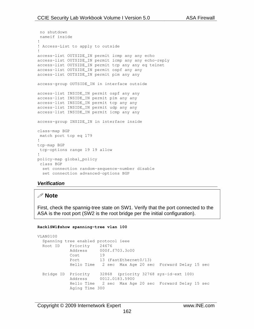
CCIE Security Lab Workbook Volume I Version 5.0 ASA Firewall
Copyright © 2009 Internetwork Expert www.INE.com162
no shutdown nameif inside ! ! Access-List to apply to outside ! access-list OUTSIDE_IN permit icmp any any echo access-list OUTSIDE_IN permit icmp any any echo-reply access-list OUTSIDE_IN permit tcp any any eq telnet access-list OUTSIDE_IN permit ospf any any access-list OUTSIDE_IN permit pim any any
access-group OUTSIDE_IN in interface outside
access-list INSIDE_IN permit ospf any any access-list INSIDE_IN permit pim any any access-list INSIDE_IN permit tcp any any access-list INSIDE_IN permit udp any any access-list INSIDE_IN permit icmp any any
access-group INSIDE_IN in interface inside
class-map BGP match port tcp eq 179 ! tcp-map BGP tcp-options range 19 19 allow ! policy-map global_policy class BGP set connection random-sequence-number disable set connection advanced-options BGP
Verification
Note
First, check the spannig-tree state on SW1. Verify that the port connected to the ASA is the root port (SW2 is the root bridge per the initial configuration).
Rack1SW1#show spanning-tree vlan 100
VLAN0100 Spanning tree enabled protocol ieee Root ID Priority 24676 Address 000f.f703.3c00 Cost 19 Port 13 (FastEthernet0/13) Hello Time 2 sec Max Age 20 sec Forward Delay 15 sec
Bridge ID Priority 32868 (priority 32768 sys-id-ext 100) Address 0012.0183.5900 Hello Time 2 sec Max Age 20 sec Forward Delay 15 sec Aging Time 300

CCIE Security Lab Workbook Volume I Version 5.0 ASA Firewall
Copyright © 2009 Internetwork Expert www.INE.com163
Interface Role Sts Cost Prio.Nbr Type ------------------- ---- --- --------- -------- -------------------- Fa0/3 Desg FWD 19 128.3 P2p Edge Fa0/13 Root FWD 19 128.13 P2p Fa0/23 Altn BLK 1000 128.23 P2p
Note
Check the connections established across the firewall. Notice the states created for PIM and OSPF protocols.
Rack1ASA1(config)# show conn 6 in use, 8 most used TCP outside 150.1.4.4:179 inside 150.1.3.3:22473, idle 0:00:40, bytes 508, flags UIO PIM outside 224.0.0.13 inside 136.1.100.3, idle 0:00:10, bytes 646 OSPF outside 224.0.0.5 inside 136.1.100.3, idle 0:00:04, bytes 3420 PIM outside 136.1.100.4 inside 224.0.0.13, idle 0:00:12, bytes 544 OSPF outside 136.1.100.4 inside 224.0.0.5, idle 0:00:08, bytes 3360
Note
Check OSPF and PIM neighbors at R3:
Rack1R3#show ip ospf neighbor
Neighbor ID Pri State Dead Time Address Interface 150.1.4.4 1 FULL/DR 00:00:32 136.1.100.4 FastEthernet0/0
Rack1R3#show ip pim neighbor PIM Neighbor Table Mode: B - Bidir Capable, DR - Designated Router, N - Default DR Priority, S - State Refresh Capable Neighbor Interface Uptime/Expires Ver DR Address Prio/Mode 136.1.100.4 FastEthernet0/0 00:08:09/00:01:27 v2 1 / DR S
Note
Check BGP session status:
Rack1R3#show ip bgp summary BGP router identifier 150.1.3.3, local AS number 1

CCIE Security Lab Workbook Volume I Version 5.0 ASA Firewall
Copyright © 2009 Internetwork Expert www.INE.com164
BGP table version is 1, main routing table version 1
Neighbor V AS MsgRcvd MsgSent TblVer InQ OutQ Up/Down State/PfxRcd 150.1.4.4 4 1 29 40 1 0 0 00:09:21 0
Note
Try opening a TCP session across the firewall and verify that pings work as well:
Rack1R4#telnet 150.1.3.3 Trying 150.1.3.3 ... Open
User Access Verification
Password: Rack1R3>exit
[Connection to 150.1.3.3 closed by foreign host]
Rack1R4#ping 150.1.3.3
Type escape sequence to abort. Sending 5, 100-byte ICMP Echos to 150.1.3.3, timeout is 2 seconds: !!!!! Success rate is 100 percent (5/5), round-trip min/avg/max = 1/3/4 ms

CCIE Security Lab Workbook Volume I Version 5.0 ASA Firewall
Copyright © 2009 Internetwork Expert www.INE.com165
1.42 ARP Inspection
• The firewall should enforce consistency in ARP requests and responses. • Manually configure the IP to MAC address mappings for R3 and R4 Fast
Ethernet interfaces to accomplish this. • Do not flood unmatched ARP requests between the security levels.
Configuration
Note
ARP traffic is permitted to flow across the transparent firewall to facilitate in IP address resolution. However, certain types of network attacks utilize ARP and might compromise your network security. Most common attack is know as ARP spoofing, where a malicious user sends crafted ARP packets, to poison other hosts ARP cache and pretend it is operating under a different IP address. This allows an attacker to attract traffic not intended for it, for example by taking over the default gateway’s IP.
ARP inspection prevents this type of attacks by looking inside the ARP replies/responses and seeing that the IP to MAC address bindings inside match the pre-configured table. In order to activate this feature, you must first populate the static bindings table using the command arp {iface} <IP> <MAC> which binds the IP to the MAC on the particular interface. To enable ARP inspection for ARP packets entering a particular interface use the command arp-inspection {iface} enable [flood|no-flood].The flood option permits ARP packets that contains IP addresses not matching the static table to be flooded out on other interfaces. The no-flood option will permit only valid ARP packets for IP addresses in the inspection table.
Unlike ARP Inspection in the Catalyst switches, the ASA firewall cannot use DHCP snooping to populate the ARP bindings table. Therefore, all configuration burden lies on the system administrator.
ASA1: arp inside 136.1.100.3 000f.8f14.ad20 arp outside 136.1.100.4 000f.90fb.2d21 ! arp-inspection outside enable no-flood arp-inspection inside enable no-flood

CCIE Security Lab Workbook Volume I Version 5.0 ASA Firewall
Copyright © 2009 Internetwork Expert www.INE.com166
Verification
Note
First, make sure you can ping from R3 to R4. Than, change R3’s Ethernet MAC address. After that, try pinging from R3 again. The ping would fail, as the ARP packets from R3 are no longer valid and the firewall drops them.
Rack1R3#ping 136.1.100.4
Type escape sequence to abort. Sending 5, 100-byte ICMP Echos to 136.1.100.4, timeout is 2 seconds: !!!!! Success rate is 100 percent (5/5), round-trip min/avg/max = 1/2/4 ms
Rack1R3#conf t Enter configuration commands, one per line. End with CNTL/Z. Rack1R3(config)#interface fastEthernet 0/0Rack1R3(config-if)#mac-address 000f.90fb.2d22
Rack1R3#ping 136.1.100.4
Type escape sequence to abort. Sending 5, 100-byte ICMP Echos to 136.1.100.4, timeout is 2 seconds: ..... Success rate is 0 percent (0/5)
Note
Now change the IP address of R3 to something not covered by the inspection table. After that, enable the flood option with ARP inspection. This time, the ping operation will work fine.
Rack1ASA1(config)# arp-inspection inside enable flood
Rack1R3#conf t Enter configuration commands, one per line. End with CNTL/Z. Rack1R3(config)#interface fastEthernet 0/0 Rack1R3(config-if)#ip add 136.1.100.33 255.255.255.0
Rack1R3#ping 136.1.100.4
Type escape sequence to abort. Sending 5, 100-byte ICMP Echos to 136.1.100.4, timeout is 2 seconds: !!!!! Success rate is 100 percent (5/5), round-trip min/avg/max = 1/3/4 ms

CCIE Security Lab Workbook Volume I Version 5.0 ASA Firewall
Copyright © 2009 Internetwork Expert www.INE.com167
1.43 Ethertype Access-Lists
• Block spanning-tree BPDUs going across the firewall. • Ensure there are no redundant links in VLAN 100 to avoid STP loops.
Configuration
Note
.As we know, the firewall by default allows the ARP packets and STP BPDUs (IEEE and PVST+ untagged). As for other non-IP packets, the firewall will not permit 802.2 LLC and SNAP frames – it only recognizes Ethernet II frames with the EtherType field higher or equal than 0x600. Thus, the firewall will not pass any LLC encapsulated traffic, such as CDP, VTP, UDLD or IPX. (STP BPDUs are also LLC encapsulated, by the firewall still permits them as an exception).
As for the valid Ethernet II frames, you may control them using the ethertype access-lists. The format for the access-list is:
access-list <NAME> ethertype permit <Ethertype>
There are some reserved names for MPLS, IPX Ethernet II format, AppleTalk Ethernet II frames. All those protocols have valid Ethernet II types and thus are recognized by the firewall. The special keyword bpdu allows you filtering the reception of STP BPDUs (which are in LLC format, not Ethernet II). You may use this to deny STP protocol across the transparent firewall.
When the ethertype access-list has been configured, you may apply it using the regular command access-group. Note that IP and Ethertype access-list may apply to the same interface at the same time.
In our scenario we block STP BPDUs across the firewall. Since this disables STP calculations and may result in layer 2 loop, we explicitly filter VLAN100 from the other link connecting the two switches. This leaves only one link in VLAN100 and avoid any topology loops.
ASA1: access-list NO_STP ethertype deny bpdu access-list NO_STP ethertype permit any ! access-group NO_STP in interface outside access-group NO_STP in interface inside
SW1: interface FastEthernet 0/23

CCIE Security Lab Workbook Volume I Version 5.0 ASA Firewall
Copyright © 2009 Internetwork Expert www.INE.com168
switchport trunk allowed vlan remove 100
Verification
Note
Before you applied the access-list, enable BPDU receive debugs in SW1. Note that port 13 (connected to the ASA) receives IEEE STP BPDUs. At the same time, the spanning-tree for VLAN100 shows port 13 as the root port of the topology (SW2 is the root bridge).
Rack1SW1#debug spanning-tree bpdu receive
STP: VLAN0100 rx BPDU: config protocol = ieee, packet from FastEthernet0/13 , linktype IEEE_SPANNING , enctype 2, encsize 17 STP: enc 01 80 C2 00 00 00 00 0F F7 03 3C 0C 00 26 42 42 03 STP: Data 00000000006064000FF7033C00000000006064000FF7033C00800C0000140002000F00 STP: VLAN0100 Fa0/13:0000 00 00 00 6064000FF7033C00 00000000 6064000FF7033C00 800C 0000 1400 0200 0F00 STP(100) port Fa0/13 supersedes 0
Rack1SW1#show spanning-tree vlan 100
VLAN0100 Spanning tree enabled protocol ieee Root ID Priority 24676 Address 000f.f703.3c00 Cost 19 Port 13 (FastEthernet0/13) Hello Time 2 sec Max Age 20 sec Forward Delay 15 sec
Bridge ID Priority 32868 (priority 32768 sys-id-ext 100) Address 0012.0183.5900 Hello Time 2 sec Max Age 20 sec Forward Delay 15 sec Aging Time 300
Interface Role Sts Cost Prio.Nbr Type ------------------- ---- --- --------- -------- ----------------------- Fa0/3 Desg FWD 19 128.3 P2p Edge Fa0/13 Root FWD 19 128.13 P2p Fa0/23 Altn BLK 1000 128.23 P2p
Note
Now apply the access-list and check the STP status again. This time, SW1 considers ports 13 as Designated, since it does not receive any superior BPDUs on this port. At the same time, BPDU receive debugging does not display any BPDUs received on port 13.

CCIE Security Lab Workbook Volume I Version 5.0 ASA Firewall
Copyright © 2009 Internetwork Expert www.INE.com169
Rack1SW1#show spanning-tree vlan 100
VLAN0100 Spanning tree enabled protocol ieee Root ID Priority 32868 Address 0012.0183.5900 This bridge is the root Hello Time 2 sec Max Age 20 sec Forward Delay 15 sec
Bridge ID Priority 32868 (priority 32768 sys-id-ext 100) Address 0012.0183.5900 Hello Time 2 sec Max Age 20 sec Forward Delay 15 sec Aging Time 15
Interface Role Sts Cost Prio.Nbr Type ------------------- ---- --- --------- -------- ----------------------- Fa0/3 Desg FWD 19 128.3 P2p Edge Fa0/13 Desg FWD 19 128.13 P2p
Rack1SW1#debug spanning-tree bpdu receive Spanning Tree BPDU Received debugging is on
STP: VLAN0001 rx BPDU: config protocol = ieee, packet from FastEthernet0/23 , linktype IEEE_SPANNING , enctype 2, encsize 17 STP: enc 01 80 C2 00 00 00 00 0F F7 03 3C 17 00 26 42 42 03 STP: Data 00000000002397001F6CE6870000000BDE8001000FF7033C0080170200140002000F00 STP: VLAN0001 Fa0/23:0000 00 00 00 2397001F6CE68700 00000BDE 8001000FF7033C00 8017 0200 1400 0200 0F00 STP(1) port Fa0/23 supersedes 0

CCIE Security Lab Workbook Volume I Version 5.0 ASA Firewall
Copyright © 2009 Internetwork Expert www.INE.com170
1.44 Transparent Firewall NAT
• Create new Loopback in R3 with the IP subnet 192.168.0.3/24. • The firewall should translate this subnet using the PAT IP address of
136.X.200.100. • Make sure you can ping R4 using the IP address 192.168.0.3 as the
source.
Configuration
Note
One of the new features introduces in version 8.0 was NAT support in transparent mode firewall. You may now apply NAT translations to traffic crossing the firewall, using the regular NAT rules. Remember though, that you cannot use interface PAT, as the interfaces have no IP addresses. Additionally, if the translated addresses are not on the same subnet, you will need additional static routes configured in the firewall and the upstream routers.
In our scenario, R4 is the upstream router. The firewall translates the subnet 192.168.0.0/24 into the IP 136.X.200.100. R4 does not know about the route to post-NAT IP address 136.X.200.100. Therefore, you need to configure a static route in R4 (the upstream) to the NAT pool (IP address). The next hop should point towards the downstream router – R3.
Next, the firewall, is supposed to switch packets based on the Layer 2 MAC addresses. When you enable NAT in the transparent firewall, the firewall will start switching packets matching active translation slots based on their destination IP addresses. Thus, you will need to configure static routes in the firewall for the IP address that are being translated. In our scenario this means configuring a static router for 192.168.0.0/24 subnet in the firewall.
Be careful when translating IP addresses on the same segment. When you enable NAT on the local segment, ARP inspection no longer applies. Therefore, the ARP responses might uncover the real IP addresses of the hosts in the segment, possibly causing confusion. This might be observed when trying to establish an OSPF adjacency with one of the peer’s IP address being translated.
ASA1: global (outside) 1 136.1.200.100 nat (inside) 1 192.168.0.0 255.255.255.0
route inside 192.168.0.0 255.255.255.0 136.1.100.3
R3: ip route 136.1.200.100 255.255.255.255 136.1.100.3

CCIE Security Lab Workbook Volume I Version 5.0 ASA Firewall
Copyright © 2009 Internetwork Expert www.INE.com171
R4: ip route 136.1.200.100 255.255.255.255 136.1.100.3
Verification
Note
Ping R4’s IP address off 192.168.0.3 IP address in R3 and check the translation entries in the firewall:
Rack1R3#ping 150.1.4.4 source loopback 1
Type escape sequence to abort. Sending 5, 100-byte ICMP Echos to 150.1.4.4, timeout is 2 seconds: Packet sent with a source address of 192.168.0.3 !!!!! Success rate is 100 percent (5/5), round-trip min/avg/max = 1/3/4 ms Rack1R3#
Rack1ASA1(config)# show xlate 1 in use, 2 most used PAT Global 136.1.200.100(13956) Local 192.168.0.3 ICMP id 29

CCIE Security Lab Workbook Volume I Version 5.0 ASA Firewall
Copyright © 2009 Internetwork Expert www.INE.com172
1.45 Firewall Contexts • Configure the ASA firewall to support multiple contexts mode per the
following requirements: o Context “CustomerA” interfaces: E0/1.121 (“InsideA”), E0/2
(“DMZ”), E0/0 (“Outside”). o Context “CustomerB” interfaces: E0/1.122 (“InsideB”), E0/2
(“DMZ”), E0/0 (“Outside”) with the security levels of 100, 50 and 0 respectively.
o Use the security levels of 100, 50 and 0 for the “Inside”, “DMZ” and “Outside” interfaces respectively.
• The “DMZ” and “Outside” interfaces are shared between the contexts. • Create a separate administrative context named “Admin” • Refer to the diagram for IP addressing information. (Note: the IP subnets
on the Inside interfaces overlap intentionally).
Configuration
Note
ASA firewall supports software virtualization, by means of so-called firewall contexts. Every context has its own set of routing, filtering/inspection and address translation rules. Only static routing is supported when the system is enabled for multiple-context mode. Features such as QoS and VPN are notsupported by the firewall contexts. All contexts must be in either routing or transparent firewall mode – you cannot mix modes in different contexts.
Contexts are generally useful when you have different set of security policies applied to different traffic flows. This might be the case when the firewall protects multiple customers or departments in the same organization. It is common to see other “virtualization” technologies, such as VLANs or VRFs used alongside with the firewall contexts. However, the firewall contexts have significant differences from the VRFs seen in the IOS routers, as we will discuss later.
In order to turn the firewall to the multiple contexts mode, you should enter the command mode multiple when logged via the console port (you may do this remotely, converting the existing running configuration into the so-called “admin” context, but you risk losing connection to the box). This will force mode change and reload the appliance. If you connect to the appliance the console port, you are logging into the system context. The sole purpose of this context is defining other contexts and allocating resources to them. You cannot assign any IP addresses when you are under the system context, with exception to the Management interface. You should to do the following things while logged into the system context:

CCIE Security Lab Workbook Volume I Version 5.0 ASA Firewall
Copyright © 2009 Internetwork Expert www.INE.com173
1) Configure physical interfaces. You need to un-shutdown the interfaces that you want to allocate to the contexts. If you are creating sub-interfaces using VLANs, you should do it under the system context as well.
2) Define the admin context. This is a special context that allows logging in the firewall remotely (via ssh, telnet or https). This context should be configured first, as the firewall won’t let you create any other contexts prior to designating the admin context using the global command admin-context <NAME>. When you convert from the single-context mode, the running configuration of the single mode is converted and saved as the admin context, to allow remote firewall administration. In order to access the system context remotely, you should log into the admin context using any configured remote access method and issue the command changeto context admin. Every configured context should have a configuration URL defined using the command config-url <PATH> to store its configuration. Without this command, the context configuration is incomplete. After the context has been defined, you may switch to the “in-context” configuration using the command changeto context <NAME>.
3) Define additional contexts if needed and allocate physical interfaces to the contexts. Use the command allocate-interface <Physical-Interface> [<Iface-Name>] under the context configuration mode for interface allocation. Here <Physical-Interface> is the physical interface or sub-interface name and <Iface-Name> is the name that the context sees for this interface. Using this command you can hide the real interface names from the context administrators (e.g. hide VLAN numbers), in order to provide additional level of isolation from the physical configuration.
Use the command write memory all in the system context to save all contexts configuration on the persistent storage. You may also save configuration for a context individually when logged under the particular context using the command write memory.
Physical interfaces could be shared among contexts, i.e. you may assign the same interface to different contexts. In our scenario, Ethernet0/2 and Ethernet0/0 interfaces are shared between two contexts. Interface sharing is the unique feature of the ASA firewall contexts, and this is what makes it stand apart from IOS VRF technology. When an interface is shared between two contexts, certain classification rules should be applied to determine which context the incoming packets should use. We will discuss the classification rules later.
4) Change to the context configuration, and proceed as usual. Assign interface names, security levels and IP addresses. However, this time you will need to set up static routes for subnets not directly connected to the context – even for the subnets connected to another contexts. If there is a shared physical interface

CCIE Security Lab Workbook Volume I Version 5.0 ASA Firewall
Copyright © 2009 Internetwork Expert www.INE.com174
between the contexts, each context generally have different IP and MAC addresses on this interface (it is possible to share the IP address as well, though). You may use non-overlapping subnets or simply different IPs on the same subnet. Remember, that by default both contexts will inherit the same MAC address from the shared physical interface. This might result in the firewall not being able to classify the incoming traffic properly. Use the command mac-address auto in the system context to automatically generate a MAC address for every new “virtual” interface.
ASA1/System: ! ! Configure physical interfaces ! interface Ethernet0/0 no shutdown ! interface Ethernet0/1 no shutdown ! interface Ethernet0/1.121 vlan 121 no shutdown ! interface Ethernet0/1.122 vlan 122 no shutdown ! interface Ethernet0/2 no shutdown
! ! Identify admin context first ! admin-context admin context admin config-url disk0:/admin.cfg
! ! Create context CustomerA and add interface ! Map interfaces to their “virtual” names ! context CustomerA description == CustomerA allocate-interface Ethernet0/0 outside allocate-interface Ethernet0/1.121 insideA allocate-interface Ethernet0/2 dmz config-url disk0:/CustomerA.cfg
! ! Create context CustomerB ! context CustomerB description == CustomerB allocate-interface Ethernet0/0 outside

CCIE Security Lab Workbook Volume I Version 5.0 ASA Firewall
Copyright © 2009 Internetwork Expert www.INE.com175
allocate-interface Ethernet0/1.122 insideB allocate-interface Ethernet0/2 dmz config-url disk0:/CustomerB.cfg
ASA1/CustomerA: ! ! Change to context CustomerA ! changeto context CustomerA
! ! Configure security-levels & IP addressing for interfaces ! interface insideA nameif inside security-level 100 ip address 136.1.0.12 255.255.255.0 ! interface dmz nameif dmz security-level 50 ip address 136.1.124.121 255.255.255.0 ! interface outside nameif outside security-level 0 ip address 136.1.123.121 255.255.255.0
ASA1/CustomerB: ! ! Change to context “CustomerB” and configure ! changeto context CustomerB ! interface insideB nameif inside security-level 100 ip address 136.1.0.12 255.255.255.0 ! interface dmz nameif dmz security-level 50 ip address 136.1.124.122 255.255.255.0 ! interface outside nameif outside security-level 0 ip address 136.1.123.122 255.255.255.0

CCIE Security Lab Workbook Volume I Version 5.0 ASA Firewall
Copyright © 2009 Internetwork Expert www.INE.com176
Verification
Note
Verify the context configuration while in the system context:
Rack1ASA1# show context Context Name Class Interfaces URL *admin default disk0:/admin.cfg CustomerA default Ethernet0/0,Ethernet0/1.121,
disk0:/CustomerA.cfg Ethernet0/2 CustomerB default Ethernet0/0,Ethernet0/1.122,
disk0:/CustomerB.cfg Ethernet0/2
Total active Security Contexts: 3
Rack1ASA1# show context detail Context "system", is a system resource Config URL: startup-config Real Interfaces: Mapped Interfaces: Ethernet0/0, Ethernet0/1, Ethernet0/1.121-122, Ethernet0/2, Ethernet0/3, Management0/0 Class: default, Flags: 0x00000819, ID: 0
Context "admin", has been created Config URL: disk0:/admin.cfg Real Interfaces: Mapped Interfaces: Class: default, Flags: 0x00000813, ID: 4
Context "CustomerA", has been created Desc: == CustomerA Config URL: disk0:/CustomerA.cfg Real Interfaces: Ethernet0/0, Ethernet0/1.121, Ethernet0/2 Mapped Interfaces: dmz, insideA, outside Class: default, Flags: 0x00000811, ID: 5
Context "CustomerB", has been created Desc: == CustomerB Config URL: disk0:/CustomerB.cfg Real Interfaces: Ethernet0/0, Ethernet0/1.122, Ethernet0/2 Mapped Interfaces: dmz, insideB, outside Class: default, Flags: 0x00000811, ID: 6
Context "null", is a system resource Config URL: ... null ... Real Interfaces: Mapped Interfaces: Class: default, Flags: 0x00000809, ID: 257

CCIE Security Lab Workbook Volume I Version 5.0 ASA Firewall
Copyright © 2009 Internetwork Expert www.INE.com177
1.46 Firewall Contexts Routing • Both R1 and R2 are preconfigured to use the firewall as their default
gateway. • Both security contexts in the ASA should use R3 as the default gateway. • Ensure that both firewall contexts can reach R4’s Loopback0 interface
subnet as well.
Configuration
Note
As mentioned previously, in the multiple-context mode the firewall supports only static routing. Thus, you need to configure a static route for every non-directly connected subnet for a firewall context or set up a static default route. All adjacent routers should be also configured with static routes to allow for full connectivity.
Note that firewall contexts do not share IP routing tables, and thus if you want to establish communications between the routing contexts you need either of the following:
1) Configure each context with a set of static routes for the subnets connected or located behind the other context. 2) Use an external router that has full knowledge of the subnets behind each of the contexts to provide connectivity.
Recall that physical interfaces could be shared between the contexts. In some scenarios, you may even configure the same physical interface as the inside for one context and outside for another. This is called context cascading. Look at the figure below:

CCIE Security Lab Workbook Volume I Version 5.0 ASA Firewall
Copyright © 2009 Internetwork Expert www.INE.com178
In this example, CustomerA has static default route pointing to 10.0.0.2 on the shared interface Ethernet0/1. CustomerB has static route for 172.16.0.0/24 pointing to 10.0.0.1 on the shared interface Ethernet0/1. Both contexts should have different MAC addresses on the shared interface or the routing will not work. Use the command mac-address auto to achieve this automatically.
In our scenario, there are few static routes set up: static default route and the static route for R4’s Loopback0 subnet.
ASA1/CustomerA: ! ! Change to context CustomerA ! changeto context CustomerA
! ! Static routes - dynamic routing is not possible with fw contexts ! route outside 0.0.0.0 0.0.0.0 136.1.123.3 1 route dmz 150.1.4.0 255.255.255.0 136.1.124.4 1
ASA1/CustomerB:
! ! Routing ! route outside 0.0.0.0 0.0.0.0 136.1.123.3 1 route dmz 150.1.4.0 255.255.255.0 136.1.124.4 1
Verification
Note
The connectivity could not yet be verified, as the NAT rules and the access-list entries have not been set up. See the verification part for the next task.

CCIE Security Lab Workbook Volume I Version 5.0 ASA Firewall
Copyright © 2009 Internetwork Expert www.INE.com179
1.47 Firewall Contexts Classification • The firewall should translate source IP addresses for all sessions going
from “Inside” to “DMZ” and “Outside” security-levels using the respective interfaces IP addressing.
• The above requirement should be fulfilled for both security contexts. • Allow the users on the “Inside” security levels to ping R3. • Users on the “Outside” should be able to ping and telnet to R1 using the
IP address 136.X.123.100 and access R2 using the IP 136.X.123.200. • Ensure that both R1 and R2 can ping each other as well using their
“Outside” IP addresses.
Configuration
Note
Let’s discuss how the firewall using classifies the incoming traffic. It is easy to assign an input packet to the context if the interface where it has been received is uniquely allocated to the context. For example, in our scenario any packets received on E0/1.121 are uniquely classified as belonging to “CustomerA”. However, if the interface is shared, additional rules are needed.
1) The firewall looks at the destination MAC address of the packet – the destination MAC designated the “next-hop” for the packet. The upstream router could have static routes configured with the next-hop pointing to the particular IP address on the shared interface. This would work if the subnets behind each context are non-overlapping. For example, imagine that in our scenario “InsideA” interface is on the subnet 10.0.1.0/24 and “InsideB” is on the subnet 10.0.2.0/24. You may simply configure R3 with two static routes:
ip route 10.0.1.0 255.255.255.0 136.1.123.121 ip route 10.0.2.0 255.255.255.0 136.1.123.122
Since the IPs 136.X.123.121 and 136.X.123.122 resolve to different MAC addresses, the firewall will classify based on the destination MAC address. This type of classification requires you assigning different MAC addresses on the shared interfaces, either manually or using the above-mentioned command mac-address auto. Even if the inside networks overlap, you can use static NAT rules and translate them to non-overlapping outside subnets. After this, configure static routes in the upstream router as demonstrated before.
2) If the MAC address is the same in both contexts for the same interface, the firewall attempts to use NAT configuration in every context to resolve the “conflicts”. This may happen if you intentionally assign the same IP address to

CCIE Security Lab Workbook Volume I Version 5.0 ASA Firewall
Copyright © 2009 Internetwork Expert www.INE.com180
both contexts or did not assign different MAC addresses to the shared interfaces. The firewall attempts to match the destination IP address and TCP/UDP port information in the packet with the active translation slots in every context. The context with the matching translation slot is selected as the target context. This type of classification allows sharing the same IP subnet or even IP address on the shared interface. You are not required to have unique MAC addresses in each context, as the translation slots are used for traffic classification.
3) If all contexts on the shared interface use the same IP address/MAC then you cannot access the contexts on the shared interface. For traffic destined to the firewall itself, it classifies based on the destination IP address. This is why it is generally recommended to use separate IP addresses (MAC could be the same) on the shared interfaces.
If you look at the solution for our scenario, you will see that only NAT-based classification is used. Since there are static NAT rules configured on the outside interface, you may access the translated inside IP addresses by the virtue of translation-slot based classification. Also, any inside user accessing the outside will be translated using the interface IP address. The returning traffic will be properly classified based on the IP/port information. Additionally, we set up access-list entries to permit incoming TCP connection and returning ICMP traffic.
ASA1/CustomerA: ! ! Configure static PAT on outside interface ! static (inside,outside) tcp 136.1.123.100 www 136.1.0.1 www
! ! Dynamic PAT on shared interface ! nat (inside) 1 0 0 global (dmz) 1 interface global (outside) 1 interface
! ! Basic access-list to permit mapped service ! access-list OUTSIDE_IN permit tcp any host 136.1.123.100 eq 80 access-list OUTSIDE_IN permit icmp any any echo-reply access-group OUTSIDE_IN in interface outside
! ! Basic access-list to permit pings across shared interface ! access-list DMZ_IN permit icmp any any echo-reply access-group DMZ_IN in interface dmz
ASA1/CustomerB:

CCIE Security Lab Workbook Volume I Version 5.0 ASA Firewall
Copyright © 2009 Internetwork Expert www.INE.com181
! ! NAT configurations: static rule/dynamic NAT ! static (inside,outside) tcp 136.1.123.101 23 136.1.0.2 23 nat (inside) 1 0 0 global (dmz) 1 interface global (outside) 1 interface
! ! Routing ! route outside 0.0.0.0 0.0.0.0 136.1.123.3 1 route dmz 150.1.4.0 255.255.255.0 136.1.124.4 1
! ! Access-control ! access-list OUTSIDE_IN permit tcp any host 136.1.123.101 eq 23 access-list OUTSIDE_IN permit icmp any any echo-reply access-group OUTSIDE_IN in interface outside ! access-list DMZ_IN permit icmp any any echo-reply access-group DMZ_IN in interface dmz
Verification
Note
Verify connectivity across the firewall by pinging from R1 and R3. Note that R3 pings the firewall outside IP address in CustomerA.
Rack1ASA1(config)# changeto context CustomerA ASA1/CustomerA(config)#
Rack1R1#ping 150.1.4.4
Type escape sequence to abort. Sending 5, 100-byte ICMP Echos to 150.1.4.4, timeout is 2 seconds: !!!!! Success rate is 100 percent (5/5), round-trip min/avg/max = 1/3/4 ms Rack1R1#
ASA1/CustomerA(config)# show xlate 6 in use, 6 most used PAT Global 136.1.123.100(80) Local 136.1.0.1(80) PAT Global 136.1.124.121(10) Local 136.1.0.1 ICMP id 5122 PAT Global 136.1.124.121(9) Local 136.1.0.1 ICMP id 5121 PAT Global 136.1.124.121(8) Local 136.1.0.1 ICMP id 5120 PAT Global 136.1.124.121(7) Local 136.1.0.1 ICMP id 5119 PAT Global 136.1.124.121(6) Local 136.1.0.1 ICMP id 5118
Rack1R3#ping 136.1.123.121

CCIE Security Lab Workbook Volume I Version 5.0 ASA Firewall
Copyright © 2009 Internetwork Expert www.INE.com182
Type escape sequence to abort. Sending 5, 100-byte ICMP Echos to 136.1.123.121, timeout is 2 seconds: !!!!! Success rate is 100 percent (5/5), round-trip min/avg/max = 1/2/4 ms
Rack1R1#ping 136.1.123.3
Type escape sequence to abort. Sending 5, 100-byte ICMP Echos to 136.1.123.3, timeout is 2 seconds: !!!!! Success rate is 100 percent (5/5), round-trip min/avg/max = 4/4/8 ms
ASA1/CustomerA# show xlate 6 in use, 6 most used PAT Global 136.1.123.100(80) Local 136.1.0.1(80) PAT Global 136.1.123.121(5) Local 136.1.0.1 ICMP id 5743 PAT Global 136.1.123.121(4) Local 136.1.0.1 ICMP id 5742 PAT Global 136.1.123.121(3) Local 136.1.0.1 ICMP id 5741 PAT Global 136.1.123.121(2) Local 136.1.0.1 ICMP id 5740 PAT Global 136.1.123.121(1) Local 136.1.0.1 ICMP id 5739
Note
Now try connection to HTTP port of the mapped IP address:
Rack1R3#telnet 136.1.123.100 80 Trying 136.1.123.100, 80 ... Open GET / <HTML><HEAD><TITLE>R1 Home Page</TITLE></HEAD> <BODY BGCOLOR=#FFFFFF><H1>Cisco Systems</H1><H2>Accessing Cisco 2611XM "R1"</H2>
Note
Change to the other context and repeat verifications. Ping R4 from R2 and check translation entries. Initiate connection from the outside to the mapped telnet port and see that it works. Verify that R3 may ping the outside IP address of CustomerB as well.
ASA1/CustomerA(config)# changeto context CustomerBASA1/CustomerB(config)#
Rack1R2#ping 150.1.4.4
Type escape sequence to abort. Sending 5, 100-byte ICMP Echos to 150.1.4.4, timeout is 2 seconds: !!!!! Success rate is 100 percent (5/5), round-trip min/avg/max = 1/3/4 ms

CCIE Security Lab Workbook Volume I Version 5.0 ASA Firewall
Copyright © 2009 Internetwork Expert www.INE.com183
Rack1R2#
ASA1/CustomerB(config)# show xlate 6 in use, 6 most used PAT Global 136.1.123.100(23) Local 136.1.0.1(23) PAT Global 136.1.124.122(5) Local 136.1.0.2 ICMP id 5691 PAT Global 136.1.124.122(4) Local 136.1.0.2 ICMP id 5690 PAT Global 136.1.124.122(3) Local 136.1.0.2 ICMP id 5689 PAT Global 136.1.124.122(2) Local 136.1.0.2 ICMP id 5688 PAT Global 136.1.124.122(1) Local 136.1.0.2 ICMP id 5687
Rack1R2#ping 136.1.123.3
Type escape sequence to abort. Sending 5, 100-byte ICMP Echos to 136.1.123.3, timeout is 2 seconds: !!!!! Success rate is 100 percent (5/5), round-trip min/avg/max = 1/3/8 ms
ASA1/CustomerB# show xlate 6 in use, 6 most used PAT Global 136.1.123.101(23) Local 136.1.0.2(23) PAT Global 136.1.123.122(5) Local 136.1.0.2 ICMP id 9825 PAT Global 136.1.123.122(4) Local 136.1.0.2 ICMP id 9824 PAT Global 136.1.123.122(3) Local 136.1.0.2 ICMP id 9823 PAT Global 136.1.123.122(2) Local 136.1.0.2 ICMP id 9822 PAT Global 136.1.123.122(1) Local 136.1.0.2 ICMP id 9821
Rack1R3#ping 136.1.123.122
Type escape sequence to abort. Sending 5, 100-byte ICMP Echos to 136.1.123.122, timeout is 2 seconds: !!!!! Success rate is 100 percent (5/5), round-trip min/avg/max = 1/1/4 ms
Rack1R3#telnet 136.1.123.101 Trying 136.1.123.101 ... Open
Rack1R2>

CCIE Security Lab Workbook Volume I Version 5.0 ASA Firewall
Copyright © 2009 Internetwork Expert www.INE.com184
1.48 Resource Management • Allocate the Management interface to the admin context created
previously, using the interface name “Mgmt”. • Configure the interface per the diagram using the security level of 100. • Allow SSH and Telnet connections on the management interface and
authenticate the remote connections using the local username/password pair “ADMIN/CISCO”.
• The context “CustomerA” should be allowed to have no more than 1000 host and NAT translation entries. The number of concurrent connections should be limited to 10000.
• The context “CustomerB” should be limited to no more than 500 host and xlate entries, and no more than 5000 connections.
• The admin context should use the default resource limits.
Configuration
Note
As mentioned in the previous tasks, in multiple-context mode the firewall should have special admin context designated for the purpose of managing the firewall. This context could be combined with any regular user context or be dedicated. In our scenario we configure the context to accept management connections on the Management interface of the ASA firewall.
The firewall has limited resources, shared between the contexts. The resources include concurrent connections, inspections, translation slots, management sessions (telnet, ssh and https) number of inside hosts and so on. You can find the full list in the firewall configuration guide. Some of those resources are limited based on the licensing option – e.g. the number of inside hosts. Others are limited by the firewall hardware.
In order to avoid resource contention and exhaustion, the firewall allows limiting per-context resources using the resource class concept. Every class specifies the amount of resource available to a context. Classes are assigned to the contexts to enforce the limits. By default, all contexts are assigned class “default”. Note that contexts do not “share” the particular class resources. They only inherit the resource limits set by a class.
When you create a new class, it inherits all limits from the “default” resource class. When you re-define any particular limit in the new class, you automatically override the default setting for this limit. You may also configure the default class settings and all classes will inherit these values, unless they redefine them.

CCIE Security Lab Workbook Volume I Version 5.0 ASA Firewall
Copyright © 2009 Internetwork Expert www.INE.com185
On the figure above, you can see default class defining the “hosts” limit. Two other classes - “BLUE” and “RED” inherit this limit plus unlimited settings for all other parameters. However, class “RED” redefines all limits and thus effectively does not inherit anything.
The appliance never “reserves” any resources for classes. It simply uses them to compute the resource limits and satisfies any request that is within the limit for a give class. For example, suppose the system supports up to 1000 connection maximum, and you create new class with the limit of 500 connections. You assign this class to 3 contexts. At the peak of their usage every context may request up to 500 connections, exceeding the total limit of 1000. Thus it is up to the administrator to properly set limits and prevent resource starvation.
You may set resource limits in absolute values (e.g. number of connections or hosts) or in percents of the maximum resource available. The syntax is
class <NAME> limit-resource <Resource> [<Value>|{1-100%}]

CCIE Security Lab Workbook Volume I Version 5.0 ASA Firewall
Copyright © 2009 Internetwork Expert www.INE.com186
Some resources, like Conns, Inspects and Syslogs support rate limiting, using the command limit-resource rate [{Conns|Inspects|Syslogs}|{1-100%}].
In our scenario, we limit only certain resources for two classes. All other parameters remain unlimited, as they are inherited from the default class.
ASA1/System:admin-context admin context admin allocate-interface Management0/0 Mgmt config-url disk0:/admin.cfg ! class Gold limit-resource Hosts 1000 limit-resource Xlates 1000 limit-resource Conns 10000 ! class Silver limit-resource Hosts 500 limit-resource Conns 5000 limit-resource Xlates 500 ! context admin member default ! context CustomerA member Gold ! context CustomerB member Silver
ASA1/Admin: ! ! Configure admin context ! changeto context admin
interface Mgmt nameif management security-level 100 ip address 10.0.0.12 255.255.255.0 management-only ! username ADMIN password CISCO encrypted ! aaa authentication ssh console LOCAL aaa authentication telnet console LOCAL ! telnet 0 0 management ssh 0 0 management

CCIE Security Lab Workbook Volume I Version 5.0 ASA Firewall
Copyright © 2009 Internetwork Expert www.INE.com187
Verification
Note
Verify that you can connect to the firewall on the management interface and change to the system context (this is only allowed from within the admin context).
After this, verify resource class settings.

CCIE Security Lab Workbook Volume I Version 5.0 ASA Firewall
Copyright © 2009 Internetwork Expert www.INE.com188

CCIE Security Lab Workbook Volume I Version 5.0 ASA Firewall
Copyright © 2009 Internetwork Expert www.INE.com189
1.49 Active/Standby Failover • Configure ASA1 and ASA2 into standby failover pair, with ASA1 as the
active unit. Use the hostname “ASA” for the pair. • Configure the IP addressing in the primary unit per the diagram, and
enable RIP as the routing protocol on the inside interface. • Make the configurations necessary to allow the inside hosts to ping the
outside destinations. • Configure stateful failover using E0/2 as the failover link with the name
“Failover” and the IP subnet 100.0.0.0/24. • Assign the IP addresses for the standby unit per the diagram. • The units should monitor each other across both interfaces using the
minimum poll times.
Configuration
Note
Failover allows two firewall units operating in hot standby mode. In order for two units to operate as failover pair, their hardware and software configurations must be identical. One firewall unit is designated as primary and another as secondary. Initially, the primary unit is active and the secondary is standby. At any moment of time, only one unit is active and forwards traffic, while the other remains in standby mode. When the active unit fails, the standby wakes up and takes the role of the active unit, by taking its IP/MAC addresses. Failover is available in both transparent firewall and routed modes. The firewall supports two types of failover – stateful and regular failover. During the regular failover, the states of the currently active sessions, NAT translations etc are not copied between the active and standby units. After the failover, users must re-initiate their connections. Stateful failover preserves all connection states during the failover and makes the switchover process almost seamless. The configurations of both units are kept synchronized all the time, as the commands from the active unit are always replicated to the standby.
Failover configuration always involves a failover interface, which is used to exchange information between the two units (e.g. configuration updates) and health monitoring. In stateful failover mode, the same link is used to constantly send the changing state information. This link is intended to be “reliable” as much as possible. You may designate a dedicated physical interface for failover or allocate a subinterface on any active data interface. However, it is strongly recommended to use a dedicated physical interface for stateful failover. The command to configure a failover link is: failover lan interface <name> <physical-interface>. Additionally, you need to assign IP addresses to the failover interface in order to allow information exchange using the command

CCIE Security Lab Workbook Volume I Version 5.0 ASA Firewall
Copyright © 2009 Internetwork Expert www.INE.com190
failover interface ip <name> <primary-ip> <mask> standby <secondary-ip>. The last two commands to be entered is failover lan unit {primary|secondary} to designate the primary/secondary unit and the command failover to activate the failover configuration. These four commands should be configured on both units, assigning their respective roles. After this, the firewalls will detect each other, and the secondary will replicate the configuration from the primary unit. Note that the default failover mode is stateless – if you want to enable stateful failover mode, enter the command failover link <name> <physical-iface> where <name> and <physical-iface> match the values used for the failover link.
When configuring the IP addresses on the interfaces, keep in mind that the primary and the secondary unit should have different IP addresses. Use the command ip address <IP> <Mask> standby <IP> to configure the IP addresses for the primary and secondary units at the same time when configuring the active unit.
Failover occurs under three general conditions:
1) The active unit detects system health issues (e.g. hardware, software or power failure). The active unit gives up its role to the standby firewall immediately.
2) Standby unit detects loss of contact with the active unit across the failover interface. Both units constantly send keepalive message to each other across the failover link. If the standby unit loses 3 consecutive keepalives, it will try to restore contact with the active unit. The standby unit will broadcast ARP requests out of all interfaces, asking for the IP address of the active unit. If it receives the ARP response on the failover link, nothing changes. If the reponse is only received on non-failover link, the standby unit marks the failover link as non-functional, but does not fail over. Manual intervention is required to fix the problem. If no response is received on any interface, the standby unit fails over.
3) The active unit detects loss of the monitored interfaces above the configured threshold. By default, when interface monitoring is enabled, every single physical interface failure would force the active unit to give it role to the standby. In the most simply case, if the unit detects loss of carrier on the interface, it immediately declares the interface to be down. To account for more complex cases, interface monitoring is performed by sending and receiving keepliave packets to the standby unit. If the active unity does not receive any hello packets for the duration of ½ of the hold-interval, it will attempt counting packets on the monitored interface to see if any traffic enters the interface. If this does not succeed, the unit will attempt sending ARP requests for known destinations to provoke some responses and see if this generates traffic. If all attempts to generate a receive traffic fails, the unit will initiate failover.

CCIE Security Lab Workbook Volume I Version 5.0 ASA Firewall
Copyright © 2009 Internetwork Expert www.INE.com191
By default, firewall unit monitors all physical interfaces with IP addresses assigned. At the same time, sub-interfaces are not monitored by default. You may set up unit and interface polling timers using the command failover polltime {unit|interface} msec <Hello> holdtime msec <Hold>. If needed, you may increase the threshold for the number of failed monitored interfaces using the command failover interface-policy <N>%. When this command is configured, the active unit will only initiate failover if there are <N> or more monitored interface failures or the number of failed interfaces is N% of all configured interfaces. With default settings, any single interface failure will trigger failover.
ASA1: hostname Rack1ASA ! ! Configure basic interface settings ! interface Ethernet0/1 nameif inside
ip address 136.1.110.12 255.255.255.0 standby 136.1.110.13 no shutdown
! interface Ethernet0/0 nameif outside
ip address 136.1.120.12 255.255.255.0 standby 136.1.120.13 no shutdown ! router rip version 2 no auto-summary network 136.1.0.0
! nat-control nat (inside) 1 0 0 global (outside) 1 interface
! ! Access-control ! access-list OUTSIDE_IN permit icmp any any echo-reply access-group OUTSIDE_IN in interface outside
! ! Enable the failover interface ! interface Ethernet0/2 no shut
! ! Configure failover settings ! failover lan unit primary failover lan interface failover Ethernet0/2 failover link failover Ethernet0/2

CCIE Security Lab Workbook Volume I Version 5.0 ASA Firewall
Copyright © 2009 Internetwork Expert www.INE.com192
failover interface ip failover 100.100.100.12 255.255.255.0 standby 100.100.100.13 failover
! ! Configure interface monitoring and failover policy ! monitor-interface outside monitor-interface inside
! ! Unit & interface polling ! failover polltime unit msec 200 holdtime msec 800 failover polltime interface msec 500 holdtime 5
! failover interface-policy 1
ASA2: interface Ethernet0/2 no shut ! failover lan unit secondary failover lan interface failover Ethernet0/2 failover link failover Ethernet0/2 failover interface ip failover 100.100.100.12 255.255.255.0 standby 100.100.100.13 failover
Verification
Note
Verify the configuration of the failover interface and the status of the failover. Make sure the standby unit is ready and all interfaces shows up as “Normal”.
ASA(config)# show failover interface interface failover Ethernet0/2 System IP Address: 100.100.100.12 255.255.255.0 My IP Address : 100.100.100.12 Other IP Address : 100.100.100.13
ASA(config)# show failover Failover On Failover unit Primary Failover LAN Interface: failover Ethernet0/2 (up) Unit Poll frequency 200 milliseconds, holdtime 800 milliseconds Interface Poll frequency 500 milliseconds, holdtime 5 seconds Interface Policy 1 Monitored Interfaces 2 of 250 maximum Version: Ours 8.0(4), Mate 8.0(4) Last Failover at: 19:29:21 UTC Mar 24 2009 This host: Primary - Active Active time: 114 (sec)

CCIE Security Lab Workbook Volume I Version 5.0 ASA Firewall
Copyright © 2009 Internetwork Expert www.INE.com193
slot 0: ASA5510 hw/sw rev (2.0/8.0(4)) status (Up Sys) Interface inside (136.1.110.12): Normal Interface outside (136.1.120.12): Normal slot 1: empty Other host: Secondary - Standby Ready Active time: 0 (sec) slot 0: ASA5510 hw/sw rev (2.0/8.0(4)) status (Up Sys)
Interface inside (136.1.110.13): Normal Interface outside (136.1.120.13): Normal slot 1: empty
Stateful Failover Logical Update Statistics Link : failover Ethernet0/2 (up) Stateful Obj xmit xerr rcv rerr General 19 0 15 0 sys cmd 15 0 15 0 up time 0 0 0 0 RPC services 0 0 0 0 TCP conn 0 0 0 0 UDP conn 0 0 0 0 ARP tbl 4 0 0 0 Xlate_Timeout 0 0 0 0 VPN IKE upd 0 0 0 0 VPN IPSEC upd 0 0 0 0 VPN CTCP upd 0 0 0 0 VPN SDI upd 0 0 0 0 VPN DHCP upd 0 0 0 0 SIP Session 0 0 0 0
Logical Update Queue Information Cur Max Total Recv Q: 0 2 15 Xmit Q: 0 26 148
Note
Initiate a TCP session across the firewall and then shut down the link connected t outside interface of the active unit.
Rack1R1#telnet 136.1.120.2 Trying 136.1.120.2 ... Open
User Access Verification
Password: cisco Rack1R2>
Rack1SW2#conf t Enter configuration commands, one per line. End with CNTL/Z. Rack1SW2(config)#interface fastEthernet 0/12Rack1SW2(config-if)#shutdown

CCIE Security Lab Workbook Volume I Version 5.0 ASA Firewall
Copyright © 2009 Internetwork Expert www.INE.com194
Note
Switch back to the primary unit and verify the failover status now. Note that the primary unit is now designated as “Failed” and the secondary unit is “Active” now. The outside interface of the primary unit shows up as “No Link”.
[Resuming connection 10 to ASA1 ... ]
Switching to Standby
ASA(config)# show failover Failover On Failover unit Primary Failover LAN Interface: failover Ethernet0/2 (up) Unit Poll frequency 200 milliseconds, holdtime 800 milliseconds Interface Poll frequency 500 milliseconds, holdtime 5 seconds Interface Policy 1 Monitored Interfaces 2 of 250 maximum Version: Ours 8.0(4), Mate 8.0(4) Last Failover at: 19:34:40 UTC Mar 24 2009 This host: Primary - Failed Active time: 318 (sec) slot 0: ASA5510 hw/sw rev (2.0/8.0(4)) status (Up Sys) Interface inside (136.1.110.13): Normal Interface outside (136.1.120.13): No Link (Waiting) slot 1: empty Other host: Secondary - Active Active time: 7 (sec) slot 0: ASA5510 hw/sw rev (2.0/8.0(4)) status (Up Sys) Interface inside (136.1.110.12): Normal (Waiting) Interface outside (136.1.120.12): Normal (Waiting) slot 1: empty
<snip>
Logical Update Queue Information Cur Max Total Recv Q: 0 2 55 Xmit Q: 0 26 382 ASA(config)#
Note
Interface monitoring shows that the outside interface on the primary unit has failed.
ASA(config)# show monitor-interface This host: Primary - Failed Interface inside (136.1.110.13): Normal Interface outside (136.1.120.13): No Link (Waiting) Other host: Secondary - Active

CCIE Security Lab Workbook Volume I Version 5.0 ASA Firewall
Copyright © 2009 Internetwork Expert www.INE.com195
Interface inside (136.1.110.12): Normal Interface outside (136.1.120.12): Normal (Waiting)
SCRack9AS>1
Note
At the same time, if you switch back to R1 and hit Enter a few time, you will notice that the TCP session has not been interrupted by the failover.
[Resuming connection 1 to R1 ... ]
Rack1R2> Rack1R2> Rack1R2>

CCIE Security Lab Workbook Volume I Version 5.0 ASA Firewall
Copyright © 2009 Internetwork Expert www.INE.com196
1.50 Active/Active Failover • Implement stateful failover for firewall contexts CustomerA and
CustomerB using two ASA units. • ASA1 should be active for CustomerA and standby for CustomerB. ASA2
should be active for CustomerB and standby for CustomerA. • Designate CustomerA as the admin context in your configuration. • Ensure R1 and R2 can ping R3. Apply NAT configurations and static
routing to accomplish this. • Use interface Ethernet 0/2 as the stateful failover link with the IP
addresses assigned per the diagram. • Disable outside interface monitoring and configure the firewall to monitor
the inside sub-interfaces. Reduce the interface polling timers to the minimum.
Configuration
Note
When configuring failover, it is mandatory to set both firewall in either single or multiple context mode simultaneously. The firewall in multiple-context mode is configured for Active/Standby failover using the same commands entered under the system context. Failover interface is also configured under the system context. However, the multiple contexts mode has unique failover feature known as Active/Active failover. With A/A failover, one unit is active for a group of security contexts and standby for another group. At the same time, the other unit is active for the “complimentary” set of the firewall contexts. Thus, there are no longer purely active and purely standby units – both units forward traffic at the same time. Still, there are primary and secondary boxes, with respect to failover configuration – the primary unit replicates all system context configurations to the secondary unit.
Active/Active failover is implemented using failover groups. There could be two groups per a failover pair. In order to implement A/A failover, you configure one firewall unit as primary for the group and secondary for another group. After this, you assign firewall contexts to the groups. Every firewall will become active for the failover group where it is primary and standby for the group where it is secondary. If one of the units fails, the respective contexts will “migrate” to the working unit. Use the command failover group {1|2} to enter the firewall group configuration. Under the group configuration, you can issue the command primary or secondary to specify the firewall role for this group. Another important command here is preempt, which instructs the “primary” firewall to take over the contexts when it becomes active again. By default, if a unit fails and the other unit takes over its contexts, the contexts are not “returned” back

CCIE Security Lab Workbook Volume I Version 5.0 ASA Firewall
Copyright © 2009 Internetwork Expert www.INE.com197
automatically when the original unit comes back. By entering the preemptcommand the group, you enable the lower priority preemption behavior. Finally, to assign the context to a failover group, use the command join-failover-group {1|2} under the context creation mode, when logged into the system context. It is important to note that failover is group-wide. If a failover event occurs, the whole group fails over to the standby unity, meaning all contexts assigned to the single group.
The last thing that differs for multiple-context mode is interface monitoring. By default, all physical interfaces mapped to a context and configured with the IP addresses are monitored. The monitored interfaces statistics is aggregated per-group. As soon as the number of failed interfaces exceeds the per-group threshold, the whole group fails over to the standby unit. The command to monitor an interface remains the same monitor-interface <interface-name>, but this time you apply it when logged under the particular context. Failover based on interface monitoring only works for Active/Active mode (not Active/Standby) as you cannot monitor any interfaces under the system context. Due to the group-wide failover behavior, the poll timers are now specific per group. In order to configure the timers, you need to access the system context and enter the failover group {1|2} configuration mode. The command remains the same – polltime interface. Here you can also set the interface-policy threshold, which applies to all failed interfaces within all contexts mapped to this group.
ASA1: hostname Rack1ASA ! ! Configure physical interfaces ! interface Ethernet0/0 no shutdown ! interface Ethernet0/1 no shutdown ! interface Ethernet0/1.121 vlan 121 no shutdown ! interface Ethernet0/1.122 vlan 122 no shutdown
! ! Create context CustomerA and add interface ! admin-context CustomerA context CustomerA description == CustomerA allocate-interface Ethernet0/0

CCIE Security Lab Workbook Volume I Version 5.0 ASA Firewall
Copyright © 2009 Internetwork Expert www.INE.com198
allocate-interface Ethernet0/1.121 config-url disk0:/CustomerA.cfg context admin
! ! Create context CustomerB! context CustomerB description == CustomerB allocate-interface Ethernet0/0 allocate-interface Ethernet0/1.122 config-url disk0:/CustomerB.cfg
ASA1/CustomerA: ! ! Change to context CustomerA ! changeto context CustomerA
! ! Configure security-levels & IP addressing for interfaces ! interface Ethernet0/1.121 nameif inside security-level 100 ip address 10.0.0.12 255.255.255.0 standby 10.0.0.13 ! interface Ethernet0/0 nameif outside security-level 0 ip address 136.1.130.100 255.255.255.0 standby 136.1.130.101
! ! Dynamic PAT on shared interface ! nat (inside) 1 0 0 global (outside) 1 interface
! ! Basic access-list to permit pings from inside ! access-list OUTSIDE_IN permit icmp any any echo-reply access-group OUTSIDE_IN in interface outside
! ! Interface Monitoring ! monitor-interface inside no monitor-interface outside
ASA1/CustomerB: changeto context CustomerB ! interface Ethernet0/1.122 nameif inside security-level 100
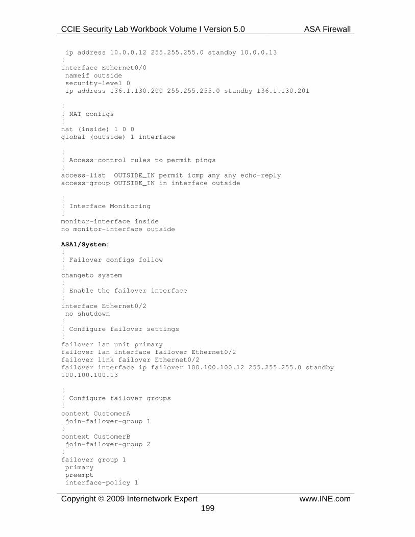
CCIE Security Lab Workbook Volume I Version 5.0 ASA Firewall
Copyright © 2009 Internetwork Expert www.INE.com199
ip address 10.0.0.12 255.255.255.0 standby 10.0.0.13 ! interface Ethernet0/0 nameif outside security-level 0 ip address 136.1.130.200 255.255.255.0 standby 136.1.130.201
! ! NAT configs ! nat (inside) 1 0 0 global (outside) 1 interface
! ! Access-control rules to permit pings ! access-list OUTSIDE_IN permit icmp any any echo-reply access-group OUTSIDE_IN in interface outside
! ! Interface Monitoring ! monitor-interface inside no monitor-interface outside
ASA1/System: ! ! Failover configs follow ! changeto system ! ! Enable the failover interface ! interface Ethernet0/2 no shutdown ! ! Configure failover settings ! failover lan unit primary failover lan interface failover Ethernet0/2 failover link failover Ethernet0/2 failover interface ip failover 100.100.100.12 255.255.255.0 standby 100.100.100.13
! ! Configure failover groups ! context CustomerA join-failover-group 1
! context CustomerB join-failover-group 2
! failover group 1 primary preempt interface-policy 1

CCIE Security Lab Workbook Volume I Version 5.0 ASA Firewall
Copyright © 2009 Internetwork Expert www.INE.com200
polltime interface msec 500 holdtime 5 ! failover group 2 secondary
preempt interface-policy 1 polltime interface msec 500 holdtime 5
! failover
ASA2: ! ! Enable failover interface ! interface Ethernet0/2 no shutdown
! failover lan unit secondary failover lan interface failover Ethernet0/2 failover link failover Ethernet0/2 failover interface ip failover 100.100.100.12 255.255.255.0 standby 100.100.100.13 failover
Verification
Note
Verify the failover pair status on ASA1. Notice that ASA1 is active for group 1 and standby for group 2. Also, notice that the outside interfaces are not monitored per out configuration.
ASA(config)# show failover Failover On Failover unit Primary Failover LAN Interface: failover Ethernet0/2 (up) Unit Poll frequency 1 seconds, holdtime 15 seconds Interface Poll frequency 5 seconds, holdtime 25 seconds Interface Policy 1 Monitored Interfaces 2 of 250 maximum Version: Ours 8.0(4), Mate 8.0(4) Group 1 last failover at: 18:03:00 UTC Mar 25 2009 Group 2 last failover at: 18:02:58 UTC Mar 25 2009
This host: Primary Group 1 State: Active Active time: 13 (sec) Group 2 State: Standby Ready Active time: 0 (sec)
slot 0: ASA5510 hw/sw rev (2.0/8.0(4)) status (Up Sys) CustomerA Interface inside (10.0.0.12): Normal

CCIE Security Lab Workbook Volume I Version 5.0 ASA Firewall
Copyright © 2009 Internetwork Expert www.INE.com201
CustomerA Interface outside (136.1.130.100): Normal (Not-Monitored) CustomerB Interface inside (10.0.0.12): Normal CustomerB Interface outside (136.1.130.200): Normal (Not-Monitored) slot 1: empty
Other host: Secondary Group 1 State: Standby Ready Active time: 0 (sec) Group 2 State: Active Active time: 18 (sec)
slot 0: ASA5510 hw/sw rev (2.0/8.0(4)) status (Up Sys) CustomerA Interface inside (10.0.0.13): Normal CustomerA Interface outside (136.1.130.101): Normal (Not-Monitored) CustomerB Interface inside (10.0.0.13): Normal CustomerB Interface outside (136.1.130.201): Normal (Not-Monitored) slot 1: empty
Note
Now test failover for the context CustomerA. First check that the inside interface for this context is monitored.
ASA/CustomerA(config)# show monitor-interface This host: Primary - Active Interface inside (10.0.0.12): Normal Other host: Secondary - Standby Ready Interface inside (10.0.0.13): Normal
Note
Now configure SW1 to filter VLAN 121 from the trunk link connecting to ASA1’s Ethernet 0/1 interface. This will make CustomerA’s inside interface connectivity test fail and force failover. As a result, ASA2 will become active for both contexts.
Rack1SW1#conf t Enter configuration commands, one per line. End with CNTL/Z. Rack1SW1(config)#interface fastEthernet 0/13Rack1SW1(config-if)#switchport trunk allowed vlan remove 121
ASA/CustomerA(config)# show monitor-interface This host: Primary - Failed Interface inside (10.0.0.13): Failed (Waiting) Other host: Secondary - Active Interface inside (10.0.0.12): Normal (Waiting)

CCIE Security Lab Workbook Volume I Version 5.0 ASA Firewall
Copyright © 2009 Internetwork Expert www.INE.com202
Note
Check the failover status again. This time, notice that ASA2 is active for both groups, and ASA1 marks group 1 as “Failed”.
ASA(config)# show failover Failover On Failover unit Primary Failover LAN Interface: failover Ethernet0/2 (up) Unit Poll frequency 1 seconds, holdtime 15 seconds Interface Poll frequency 5 seconds, holdtime 25 seconds Interface Policy 1 Monitored Interfaces 2 of 250 maximum Version: Ours 8.0(4), Mate 8.0(4) Group 1 last failover at: 18:17:51 UTC Mar 25 2009 Group 2 last failover at: 18:02:58 UTC Mar 25 2009
This host: Primary Group 1 State: Failed Active time: 891 (sec) Group 2 State: Standby Ready Active time: 0 (sec)
slot 0: ASA5510 hw/sw rev (2.0/8.0(4)) status (Up Sys) CustomerA Interface inside (10.0.0.13): Failed (Waiting) CustomerA Interface outside (136.1.130.101): Normal (Not-Monitored) CustomerB Interface inside (10.0.0.13): Normal CustomerB Interface outside (136.1.130.201): Normal (Not-Monitored) slot 1: empty
Other host: Secondary Group 1 State: Active Active time: 45 (sec) Group 2 State: Active Active time: 940 (sec)
slot 0: ASA5510 hw/sw rev (2.0/8.0(4)) status (Up Sys) CustomerA Interface inside (10.0.0.12): Normal (Waiting) CustomerA Interface outside (136.1.130.100): Normal (Not-Monitored) CustomerB Interface inside (10.0.0.12): Normal CustomerB Interface outside (136.1.130.200): Normal (Not-Monitored) slot 1: empty

CCIE Security Lab Workbook Volume I Version 5.0 ASA Firewall
Copyright © 2009 Internetwork Expert www.INE.com203
1.51 ASA Redundant Interfaces • Configure the firewall so that E0/2 and E0/0 interface represent a single
logical interface. • If the E0/0 interface fails, the E0/2 should take it place. • The new interface should be used for DMZ and Outside logical interface • Use the VLAN numbers and the IP addressing per the diagram to
accomplish this.
Configuration
Note
A logical redundant interface is a pair an active and a standby physical interface. When the active interface fails, the standby interface becomes active. From the perspective of the firewall applications, this event is completely transparent, as the interface pair is viewed as a single logical interface. You can use redundant interfaces to increase the security appliance reliability. This feature is separate from device-level failover, but you can configure redundant interfaces as well as failover if desired. You can configure up to 8 redundant interfaces. Notice that this method has its limitation – the detection of interface failure is based on simple physical monitoring. When the primary interface loses a carrier, it is declared as failed.
Redundant interface are numbered from 1 to 8 and have the name redundant x. When adding physical interfaces to the redundant pair, make sure they are not configured using the nameif command and are in no shutdown state. This is just a precaution, the firewall will remove these settings when adding the physical interface to a new group. The logical redundant interface will take the MAC address of the first interface added to the group. This MAC address is not changed with the member interface failures, but changes when you swap the order of the physical interfaces added to the pair.
As soon as you have configured a redundant interface, you may assign it a name and a security level, followed by an IP address. The procedure is the same as with any interface in the system.
In this task, pay attention that we replace two separate interfaces with a single logical redundant interface. To accomplish the link splitting, we use VLAN subinterfaces, which are configured with the IP addresses and security level.
ASA1: interface Ethernet 0/0 no ip address no nameif

CCIE Security Lab Workbook Volume I Version 5.0 ASA Firewall
Copyright © 2009 Internetwork Expert www.INE.com204
! interface Ethernet 0/2 no ip address no nameif ! ! Configure the redundant interface ! interface redundant 1 member-interface Ethernet 0/0 member-interface Ethernet 0/2 ! ! Configure subinterfaces ! interface redundant 1.122 vlan 122 nameif outside ip address 136.1.122.12 255.255.255.0 ! interface redundant 1.120 vlan 120 nameif dmz security-level 50 ip address 10.0.0.12 255.255.255.0
SW2: interface range FastEthernet 0/12 - 13 no shutdown switchport trunk encapsulation dot1q switchport mode trunk
Verification
Note
Check the redundant interface status and test connectivity to R2 and the AAA server.
Rack1ASA1(config-subif)# show interface redundant 1 detail Interface Redundant1 "", is up, line protocol is up Hardware is i82546GB rev03, BW 100 Mbps, DLY 100 usec Auto-Duplex(Full-duplex), Auto-Speed(100 Mbps) Available but not configured via nameif MAC address 0021.554f.3108, MTU not set IP address unassigned 625 packets input, 49071 bytes, 0 no buffer Received 483 broadcasts, 0 runts, 0 giants 0 input errors, 0 CRC, 0 frame, 0 overrun, 0 ignored, 0 abort 228 L2 decode drops 83 packets output, 8512 bytes, 0 underruns 0 output errors, 0 collisions, 1 interface resets 0 babbles, 0 late collisions, 0 deferred 0 lost carrier, 0 no carrier input queue (curr/max packets): hardware (1/18) software (0/0) output queue (curr/max packets): hardware (0/2) software (0/0)

CCIE Security Lab Workbook Volume I Version 5.0 ASA Firewall
Copyright © 2009 Internetwork Expert www.INE.com205
Control Point Interface States: Interface number is 8 Interface config status is active Interface state is active Redundancy Information: Member Ethernet0/0(Active), Ethernet0/2 <snip>
Rack1ASA1(config-subif)# ping 10.0.0.100 Type escape sequence to abort. Sending 5, 100-byte ICMP Echos to 10.0.0.100, timeout is 2 seconds: !!!!! Success rate is 100 percent (5/5), round-trip min/avg/max = 1/1/1 ms
Rack1ASA1(config-subif)# ping 136.1.122.2 Type escape sequence to abort. Sending 5, 100-byte ICMP Echos to 136.1.122.2, timeout is 2 seconds: !!!!! Success rate is 100 percent (5/5), round-trip min/avg/max = 1/2/10 ms
Note
Now shut down the first interface in the pair. Check the connectivity again and look at the redundant interface status. Notice that now the active physical interface is E0/2.
Rack1SW2(config-if)#interface fastEthernet 0/12 Rack1SW2(config-if)#shutdown Rack1SW2(config-if)#
Rack1ASA1(config-subif)# ping 136.1.122.2 Type escape sequence to abort. Sending 5, 100-byte ICMP Echos to 136.1.122.2, timeout is 2 seconds: !!!!! Success rate is 100 percent (5/5), round-trip min/avg/max = 1/1/1 ms
Rack1ASA1(config-subif)# ping 10.0.0.100 Type escape sequence to abort. Sending 5, 100-byte ICMP Echos to 10.0.0.100, timeout is 2 seconds: !!!!! Success rate is 100 percent (5/5), round-trip min/avg/max = 1/1/1 ms
Rack1ASA1(config-subif)# show interface redundant 1 Interface Redundant1 "", is up, line protocol is up Hardware is i82546GB rev03, BW 100 Mbps, DLY 100 usec Auto-Duplex(Full-duplex), Auto-Speed(100 Mbps) Available but not configured via nameif MAC address 0021.554f.3108, MTU not set IP address unassigned 509 packets input, 39816 bytes, 0 no buffer Received 394 broadcasts, 0 runts, 0 giants 0 input errors, 0 CRC, 0 frame, 0 overrun, 0 ignored, 0 abort 228 L2 decode drops 69 packets output, 6982 bytes, 0 underruns

CCIE Security Lab Workbook Volume I Version 5.0 ASA Firewall
Copyright © 2009 Internetwork Expert www.INE.com206
0 output errors, 0 collisions, 1 interface resets 0 babbles, 0 late collisions, 0 deferred 0 lost carrier, 0 no carrier input queue (curr/max packets): hardware (1/18) software (0/0) output queue (curr/max packets): hardware (0/2) software (0/0) Redundancy Information: Member Ethernet0/2(Active), Ethernet0/0 Last switchover at 13:15:50 UTC Jun 6 2009

CCIE Security Lab Workbook Volume I Version 5.0 ASA Firewall
Copyright © 2009 Internetwork Expert www.INE.com207
1.52 ASA Enhanced Object Groups • Configure the firewall to permit telnet, ping and syslog traffic from R2 to
R1. • Use only a single access-list statement to accomplish this.
Configuration
Note
As you remember, object groups allow for combining of objects of the same type (e.g. TCP or UDP port numbers, ICMP error codes) in a single unit. Enhanced service object-groups allow combining different IP protocols (e.g. TCP/ICMP) together in the same service group. This eliminates the need for the specific object groups. This feature is available on ASA code since version 8.0. The key configuration commands are object-group service and service-object <protocol> inside the new object group. Since the object-group mixes different protocol types, it should be applied differently inside an access-list. The syntax is:
access-list <NAME> permit object-group <OG_NAME> <src> <dst>
e.g.
access-list TEST permit object-group PROTOCOLS host 1.1.1.1 any
ASA1: object-group service R2_APPS service-object icmp echo service-object tcp eq telnet service-object udp eq syslog ! access-list OUTSIDE_IN permit object-group R2_APPS host 136.1.122.2 any ! access-group OUTSIDE_IN in interface outside
Verification
Note
Try generating ICMP and TCP traffic off R2 and make sure it passes across the firewall.
Rack1R2#telnet 150.1.1.1 Trying 150.1.1.1 ... Open

CCIE Security Lab Workbook Volume I Version 5.0 ASA Firewall
Copyright © 2009 Internetwork Expert www.INE.com208
User Access Verification
Password: Rack1R1>exit
[Connection to 150.1.1.1 closed by foreign host] Rack1R2#ping 150.1.1.1
Type escape sequence to abort. Sending 5, 100-byte ICMP Echos to 150.1.1.1, timeout is 2 seconds: !!!!! Success rate is 100 percent (5/5), round-trip min/avg/max = 4/4/4 ms
Note
Check the access-list in the firewall after this. Notice the hit counts in the output.
Rack1ASA1(config)# show access-list access-list cached ACL log flows: total 0, denied 0 (deny-flow-max 4096) alert-interval 300 access-list OUTSIDE_IN; 3 elements access-list OUTSIDE_IN line 1 extended permit object-group R2_APPS host 136.1.122.2 any 0xa7a577cd access-list OUTSIDE_IN line 1 extended permit icmp host 136.1.122.2 any echo (hitcnt=1) 0xcfb23ccc access-list OUTSIDE_IN line 1 extended permit tcp host 136.1.122.2 any eq telnet (hitcnt=1) 0x249cedab access-list OUTSIDE_IN line 1 extended permit udp host 136.1.122.2 any eq syslog (hitcnt=0) 0x9b67ccec