iet generation, transmission & distribution for dc ...pe.csu.edu.cn/lunwen/54 distributed...
TRANSCRIPT
IET Generation, Transmission & Distribution
Research Article
Distributed control scheme on costoptimisation under communication delays forDC microgrids
ISSN 1751-8687Received on 1st November 2016Revised 1st June 2017Accepted on 12th July 2017E-First on 25th August 2017doi: 10.1049/iet-gtd.2016.1716www.ietdl.org
Hua Han1, Hao Wang1, Yao Sun1 , Jian Yang1, Zhangjie Liu1
1Department of Information Science and Engineering, Central South University, Minzhu Building, Changsha, People's Republic of China E-mail: [email protected]
Abstract: This study addresses the distributed economic dispatch problem for DC microgrids when time-varying delays arepresent in communication networks. A novel distributed algorithm is proposed, and the proposed controller contains adistributed generation cost optimisation module and a voltage regulation module. The cost optimisation module is aimed torealise cost optimisation by driving the incremental cost rate of every distributed generator to be equal. In the voltage regulationmodule, a distributed synchronisation algorithm is used to restore the global average voltage. After the effect of thecommunication delay on the system stability is analysed, the robust stability criticality under load changes is obtained by usinglinear matrix inequality. The performance of the proposed scheme is validated through simulations and experimentally.
1 IntroductionA resurgence in the use of DC microgrids is occurring because ofthe development and deployment of distributed generators (DGs),such as solar photovoltaic, wind power electric, and energy storagegenerators, which offer inherent advantages for loads incommercial, industrial, and residential applications [1]. Ascompared with AC microgrids, DC microgrids have uniqueadvantages, such as high capacity transmission lines, a highlyreliable power supply, and less system loss. Furthermore, thetransformer inrush current, frequency synchronisation, and reactivepower flow do not need to be considered [2, 3].
Many studies have been conducted in recent years on economicoptimisation in DC microgrids. The centralised control strategy,with its benefits in terms of maximising economic operation andsatisfying voltage regulation, is widely applied in DC microgrids[4, 5]. However, the need for strong communication systems andthe complicated centralised controller increase the operating cost,control complexity, and communication infrastructure, which mayresult in poor power control and low reliability.
Decentralised control has been developed to replace centralisedcontrol, owing to its excellent characteristics, such as high-levelreliability and simple communication network requirements [6–8].As a classical decentralised control method, conventional droopcontrol achieves power sharing among DGs in microgrids [9].However, proportional power sharing based on power ratings alonecan ensure only that the generated power is proportional to thecapacity of a DG, which may not achieve economical operation. Acost-based droop scheme in which droop control and economicoptimisation were combined was proposed for obtaining lowergeneration costs for microgrids [10, 11]. These approaches reducethe operating costs of a microgrid to a certain extent, whichrepresents a major milestone in microgrid operation optimisation.However, droop mechanisms sometimes suffer from poor voltageregulation and load sharing, particularly when the distribution lineimpedances cannot be negligible [12, 13].
Since they combine the merits of both centralised anddecentralised approaches, the use of distributed methods in DCmicrogrids has become increasingly widespread [14–21]. Thedynamic consensus algorithm is a crucial technique in thedistributed methods for economic optimisation and can be designedto achieve power sharing [14–18], voltage restoration [19, 20], andcurrent sharing [21]. To achieve cost optimisation, an incrementalcost rate λ-consensus method was proposed to realise economicoptimisation [14, 15]. In [16], a gradient-based distributed method
was also applied to solve the cost optimisation problem in DCmicrogrids. However, the step size should be carefully chosenwhen the variables reach their constraint bounds. In order toimprove power quality, distributed consensus control methods wereproposed for realising optimal power allocation and voltagerecovery [17, 18]. Time delay arising from communication is not anegligible factor in consensus control design. However, none ofthese methods considers a theoretic analysis of the communicationdelay.
The main problem involved in consensus with time delay is theeffects of time delay on the convergence and performance ofconsensus [22–26]. Using linear matrix inequality (LMI), aconsensus algorithm for directed networks with time-varyingdelays was investigated in [24]. Recently, optimisation indistributed multi-agent coordination has been studied in terms ofconvergence speed [25] and certain specific cost functions [26]. InDC microgrids based on distributed optimisation control, acommunication delay even has a destabilising effect on the system.Thus, considering a constant communication delay, in [27, 28] thestability of the distributed optimisation DC microgrid was analysedwith a discrete-time model. The effect of communication delays onthe convergence of an economic dispatch algorithm was analysed,and the maximum allowable communication delay bounds werederived by the generalised Nyquist criterion. In [18], the effects oftime delays on the economic dispatch algorithm were examinedonly through simulations. Thus far, no report on the distributed costoptimisation of DC microgrids under load variations when time-varying delays are present has been published.
For DC microgrids with a time-variable delay in thecommunication network, this paper proposes a distributedoptimisation control method to minimise the total cost of powergeneration and restore the global average voltage. Regarding costoptimisation, each DG exchanges only the estimated value of theincremental cost rate with neighbours, which reduces thedependence on the communication bandwidth; the output power ofeach DG is based on the equal incremental principle to achieve costoptimisation. In addition, in this study, we explored the influenceof time-varying delays and analysed the robust stability criticalityof the system, taking communication delays and load parameteruncertainties into consideration. The contributions of this paper aresummarised as follows:
(i) A distributed cost optimisation control method that takes time-varying communication delay into consideration is proposed.
IET Gener. Transm. Distrib., 2017, Vol. 11 Iss. 17, pp. 4193-4201© The Institution of Engineering and Technology 2017
4193

(ii) It is shown that, when the load varies under communicationdelay conditions, the control method can also be used, and asatisfactory transient process can be achieved.(iii) The criticalities of the robust stability of the system areobtained by LMI.
2 Cost optimisation problem of DC microgrids2.1 Cost functions for DC distributed generators
In general, the generation cost of a DG depends on its operationalcharacteristics and rating. Therefore, the generation costs ofdifferent DGs cannot be represented by a common function. Thedistributed system examined in this study is shown in Fig. 1.
The common cost functions of conventional generators, such asdiesel generators, micro turbines, and energy storage equipment,are represented as [12]
Ci Pi = Km, iPi + K f , i ai + biPi + ciPi2
+Kξ, i αi + βiPi + γiPi2 + εiexp(ρiPi)
(1)
where i represents the DG number, Pi is the output power of the ithDG, constants ai, bi, and ci represent the fuel consumptionbehaviour of the combustion engine, αi, βi, γi, ɛi, and ρi representthe emission penalty or incentive, and Km,i, Kf,i, and Kζ,i are theequivalent cost coefficients of the active power, consumption of thecombustion engine, and emission penalty, respectively.
Being of different types, the cost functions of dispatchablegreen sources, such as fuel cell, wind, and photovoltaic sources,with storage components can be alternatively derived from theirdirect operating costs and converter loss-efficiency functions [13,29]
Ci Pi = Ko, i Pi + Kl, i vi + uiPi + wiPi2 (2)
where KO,i, Kl,i, υi, ui, and ωi are constants for the consideredsource.
In fact, in addition to the DGs mentioned above, in DCmicrogrids, energy storage systems (ESSs) are importantcomponents. However, the generation cost function for the energystorage can be approximately seem as that of conventional powergeneration units [18]. Thus, this paper does not specifically discussthe cost of ESS, and presents several common DGs as an exampleto explore the effectiveness of the proposed control.
To compare the cost of all DGs on an equal scale, all the costfunctions were normalised based on their respective power ratings,as given by
Pi′ = PiPmax, i
, Ci′ Pi = Ci P′i (3)
where Ci′ Pi (i = 1, 2, …, n) represents the DGs’ cost functions.
2.2 DC microgrid cost optimisation problem
Mathematically, the minimum generation cost can be obtained bysolving the following optimisation problem. The objective functionis represented as
J = min ∑i = 1
nC′i Pi (4)
First, the output power of all the DGs in a DC microgrid must meetthe requirement of the total loads
Pload = ∑i = 1
nPi (5)
According to the given objective function and constraints, theLagrange function is established as
L P1, P2, …, Pn, λ = ∑i = 1
nC′i Pi − λ ∑
i = 1
nPi − Pload (6)
where λ is the Lagrange multiplier. Thus, the conditional extremumproblem is changed into a non-constrained optimal problem.Because the cost function is strictly convex and differentiable, theminimum of the Lagrange function is achieved by solving theequations
∂L∂Pi
= ∂C′i Pi∂Pi
− λ = 0
∂L∂λ = ∑
i = 1
nPi − Pload = 0
(i = 1, 2, …, n) (7)
Then, we obtain
∂C′1 P1
∂P1− λ = ∂C′2 P2
∂P2− λ = ⋯
= ∂C′n Pn∂Pn
− λ = ∑i = 1
nPi − Pload = 0
(8)
Let f i Pi = ((∂Ci′(Pi))/∂Pi); then, we have
f 1 P1 = f 2 P2 = ⋅ ⋅ ⋅ = f n Pn = λ (9)
Using (8) and (9), it is easy to obtain the optimal output voltage ofeach DG for centralised control, because centralised control cancollect the cost increment rate, λi i = 1, 2, …, n , of all the DGs.Then, each DG can generate power according to the optimal powerdistributed. However, the need for strong communication links anda complicated centralised controller increases the operating costand control complexity, and thus, many studies were focused onthe study of distributed control.
3 Distributed control methods with considerationof communication delayIn order to achieve both cost optimisation and voltage restorationwhen time-varying communication delays are present, a unifieddistributed control method is proposed.
3.1 Proposed distributed minimum-cost control scheme
A novel distributed synchronisation control method is proposed:
Fig. 1 Configuration of communication and physical connection
4194 IET Gener. Transm. Distrib., 2017, Vol. 11 Iss. 17, pp. 4193-4201© The Institution of Engineering and Technology 2017
ui = uref + ∫ h λi − ui ⋅ ii dt
λi = k1 ∑j ∈ Ni, j ≠ i
ai j λj(t − τ(t)) − λi(t − τ(t)) − k2 λi(t − τ(t)) − λ0
λ0 = ∫ uref − u^i t − τ t dt
(10a–c)
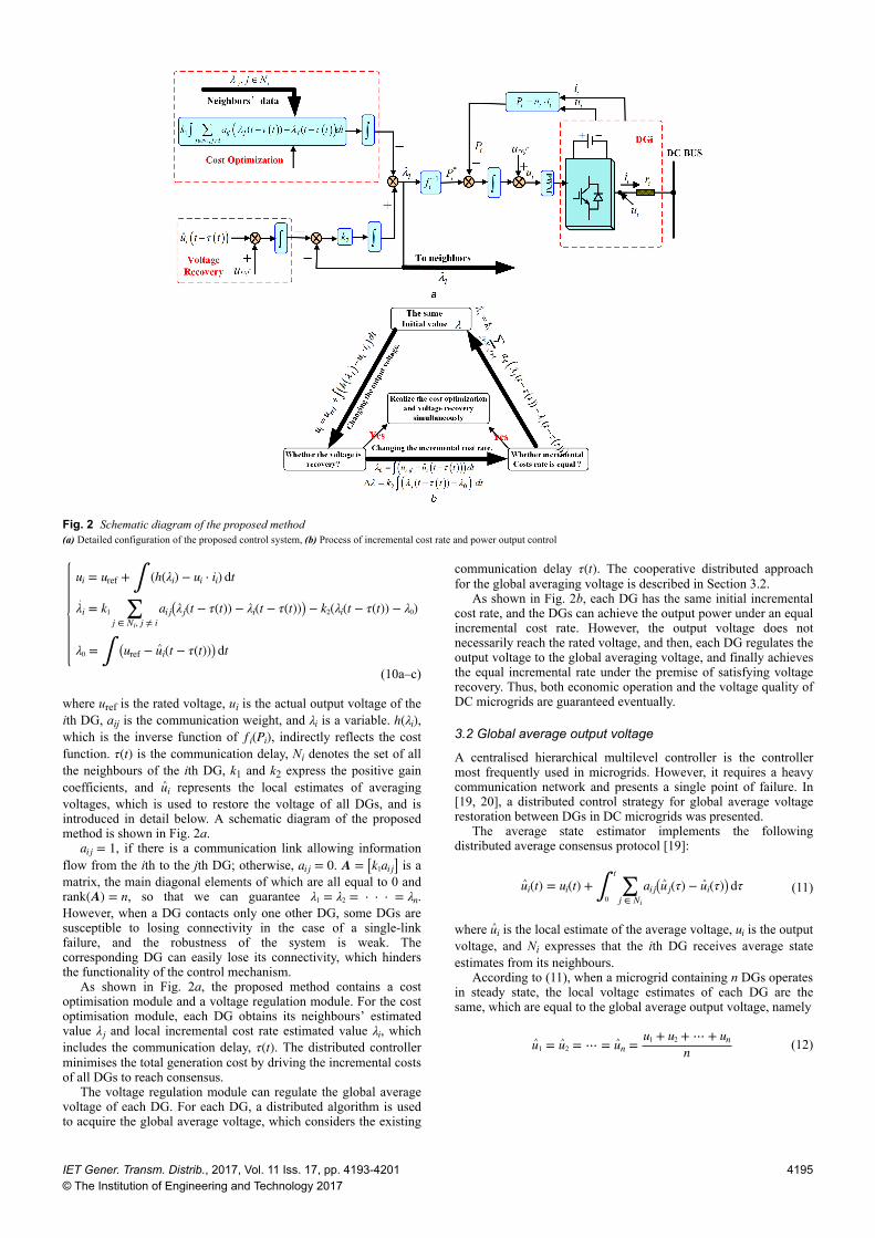
where uref is the rated voltage, ui is the actual output voltage of theith DG, aij is the communication weight, and λi is a variable. h λi ,which is the inverse function of f i Pi , indirectly reflects the costfunction. τ t is the communication delay, Ni denotes the set of allthe neighbours of the ith DG, k1 and k2 express the positive gaincoefficients, and u^i represents the local estimates of averagingvoltages, which is used to restore the voltage of all DGs, and isintroduced in detail below. A schematic diagram of the proposedmethod is shown in Fig. 2a.
ai j = 1, if there is a communication link allowing informationflow from the ith to the jth DG; otherwise, ai j = 0. A = k1ai j is amatrix, the main diagonal elements of which are all equal to 0 andrank A = n, so that we can guarantee λ1 = λ2 = ⋅ ⋅ ⋅ = λn.However, when a DG contacts only one other DG, some DGs aresusceptible to losing connectivity in the case of a single-linkfailure, and the robustness of the system is weak. Thecorresponding DG can easily lose its connectivity, which hindersthe functionality of the control mechanism.
As shown in Fig. 2a, the proposed method contains a costoptimisation module and a voltage regulation module. For the costoptimisation module, each DG obtains its neighbours’ estimatedvalue λj and local incremental cost rate estimated value λi, whichincludes the communication delay, τ t . The distributed controllerminimises the total generation cost by driving the incremental costsof all DGs to reach consensus.
The voltage regulation module can regulate the global averagevoltage of each DG. For each DG, a distributed algorithm is usedto acquire the global average voltage, which considers the existing
communication delay τ t . The cooperative distributed approachfor the global averaging voltage is described in Section 3.2.
As shown in Fig. 2b, each DG has the same initial incrementalcost rate, and the DGs can achieve the output power under an equalincremental cost rate. However, the output voltage does notnecessarily reach the rated voltage, and then, each DG regulates theoutput voltage to the global averaging voltage, and finally achievesthe equal incremental rate under the premise of satisfying voltagerecovery. Thus, both economic operation and the voltage quality ofDC microgrids are guaranteed eventually.
3.2 Global average output voltage
A centralised hierarchical multilevel controller is the controllermost frequently used in microgrids. However, it requires a heavycommunication network and presents a single point of failure. In[19, 20], a distributed control strategy for global average voltagerestoration between DGs in DC microgrids was presented.
The average state estimator implements the followingdistributed average consensus protocol [19]:
u^i t = ui t + ∫0
t∑
j ∈ Ni
ai j u^ j τ − u^i τ dτ (11)
where u^i is the local estimate of the average voltage, ui is the outputvoltage, and Ni expresses that the ith DG receives average stateestimates from its neighbours.
According to (11), when a microgrid containing n DGs operatesin steady state, the local voltage estimates of each DG are thesame, which are equal to the global average output voltage, namely
u^1 = u^2 = ⋯ = u^n = u1 + u2 + ⋯ + unn (12)
Fig. 2 Schematic diagram of the proposed method(a) Detailed configuration of the proposed control system, (b) Process of incremental cost rate and power output control
IET Gener. Transm. Distrib., 2017, Vol. 11 Iss. 17, pp. 4193-4201© The Institution of Engineering and Technology 2017
4195

4 DC microgrids stability analysis4.1 Steady-state analysis
A definite system including DGs, a resistive load, and lineresistances, can be regarded as an n-port network, where all DGsand loads are nodes. When the system is in steady state, accordingto Kirchhoff's voltage and current theorem [30]
iiload
=Lss Lsl
Lls Lll
uuload
(13)
where u = u1 u2 ⋯ unT, i = i1 i2 ⋯in T,
uload = uload1 uload2 ⋯ uloadnT, iload = iload1 iload2 ⋯ iloadn
T,Lss ∈ Rn × n, Lsl ∈ Rn × m, Lls ∈ Rm × n, and Lll ∈ Rm × m are constantmatrices, which are determined by the line resistance and load ofthe system. The load node is
iloadi = Ri ⋅ uloadi (14)
where R = diag Ri . According to (13) and (14), we have
i = Yu (15)
where Y = Lss + LslR I − LllR −1Lls = Lss − Lsl Lll − R−1 −1Lls,which is an admittance matrix, and I = diag 1 . According to thecost optimisation module, the distributed controller minimises thetotal generation cost by driving the incremental costs rate of allDGs to reach consensus. When the system operates in steady state,all the incremental costs rates, λi, are equal, namely
λ1 = λ2 = ⋯ = λn (16)
Based on the voltage restoration module, the global average outputvoltage can be restored. When the system is in steady state
u1 + u2 + ⋯ + unn = uref (17)
h λi = ui ⋅ ii (18)
By using (15)–(18), the incremental costs rate λi(i = 1, 2, …, n),output voltage ui(i = 1, 2, …, n), and current i i(i = 1, 2, …, n) ofeach DG in steady state can be solved.
4.2 Stability analysis
In this study, two classes of uncertainties, communication delayτ t and load change, were investigated.
The dynamics function of the output voltage ui and costincrement rate λi is represented by (10). The derivation on bothsides of (10) is taken, and we obtain (see (19)) wheredi = ∑ j ∈ Ni ai j and the time delay τ t is a time-varyingdifferentiable function that satisfies
0 ≤ τ t ≤ c and τ t < μ (20)
where c > 0 and μ are constants.When the system is in steady state, the local estimate of average
voltage u^i and the actual global average voltage are equal, and meetthe condition represented by (12).
Let K1 = diag k1d1 , K2 = diag k2 , L = K1 + K2 − A. When thesystem operates in the equilibrium point, the linearisation functionof the output voltage and incremental cost rate can be described as
Δu = ∂h∂λ Δλ − u ⋅ Y + i Δu
Δλ = − LΔλ(t − τ(t)) + K2Δλ0
Δλ0 = CΔu(t − τ(t)
(21)
where (∂h/∂λ) = diag ∂h/∂λi = H, which is a diagonal matrix,Δλ = Δλ1, Δλ2, …, Δλn
T, Δu = Δu1, Δu2, …, ΔuiT,
Δi = Δi1, Δi2, …, Δii T, u = diag u1, u2, …, un , andi = diag i 1, i 2, …, in . C ∈ Rn × n is a matrix, all the elements ofwhich are equal to 1/n.
When the load changes, the admittance matrix Y follows thechange. Thus, Y is not a fixed matrix. When a change in the load isconsidered (see (22)) where ΔR ≪ R, because the change in asingle load is small. Let W + ΔW = i + u ⋅ Y and ΔW express theload change uncertainty
Wmax = i + u Lss + Lsl Lll − R−1 −1Lls
ΔWmax = − uLsl RLll − I −1ΔR LllR − I −1Lls(23)
where ΔRmax = Rmax − Rmin. When the system operates in steadystate, let x1 = Δu, x2 = Δλ, x3 = Δλ0; then, (21) can be described as
x1 = − W + ΔW x1 t + Hx2 tx2 = − Lx2 t − τ t + K2x3(t)x3 = Cx1 t − τ t
(24)
Accordingly, we can obtain
x = Ab + ΔAb t x t + Adx t − τ t (25)
ui = h λi − ui ⋅ ii, i ∈ 1, 2, …, n
λi = k1 ⋅ ∑j ∈ Ni, j ≠ i
ai jλj(t − τ(t) − k1diλi(t − τ(t)) − k2 λi(t − τ(t) − λ0
λ0 = ure f − u^i t − τ t
(19)
Y R + ΔR = Lss − Lsl Lll − R + ΔR −1 −1Lls
= Lss − Lsl Lll − I + R−1ΔR −1R−1 −1Lls
≃ Lss − Lsl Lll − R−1 − R−1ΔRR−1 −1Lls
= Lss + Lsl I − Lll − R−1 −1R−1ΔRR−1 −1Lll − R−1 −1Lls
≃ Lss + Lsl I − Lll − R−1 −1R−1ΔRR−1 Lll − R−1 −1Lls
= Lss + Lsl Lll − R−1 −1Lls − Lsl Lll − R−1 −1R−1ΔRR−1 Lll − R−1 −1Lls
= Lss + Lsl Lll − R−1 −1Lls − Lsl RLll − I −1ΔR LllR − I −1Lls
(22)
4196 IET Gener. Transm. Distrib., 2017, Vol. 11 Iss. 17, pp. 4193-4201© The Institution of Engineering and Technology 2017

where x = x1 x2 x3T
Ab =−W H OO O K2
O O O, ΔAb =
−ΔW O OO O OO O O
, Ad =
O O OO −L OC O O
.
The uncertainties are assumed to be of the form
ΔAb t = DF t Ea (26)
where D = ΔWmax I. Ea is a constant matrix with appropriatedimensions and FT t is unknown and real-valued, and satisfiesFT t F t ≤ I.
In (25), the two classes of uncertainties, time-varying delay τ tand load change, are considered. The robust stability conditions forthis system are discussed in the following.
Given delay c > 0 and μ, the system represented by (25) isrobustly stable (for details of the Lyapunov function, see [31]) ifthere exist matrices P = PT > 0, Q = QT ≥ 0, R1 = R1
T ≥ 0,Zi = Zi
T > 0, i = 1, 2, N = N1 N2 N3T, S = S1 S2 S3
T,M = M1 M2 M3
T, where N, S, and M are freedom matrices,and a scalar λ > 0, such that the following LMI holds:
Φ^cN cS cM cAc1
T Z^ P^ D∗ −cZ1 O O O O∗ ∗ −cZ1 O O O∗ ∗ ∗ −cZ2 O O
∗ ∗ ∗ ∗ −cZ^ −cZ1D∗ ∗ ∗ ∗ ∗ −λI
< 0 (27)
where (see equation below) and * denotes the symmetric terms in asymmetric matrix.
There exist exact matricesAb, Ad, D, and Ea for a definitesystem, and then the delay upper bound c can be obtained based on(27).
5 Simulation resultsThe performance validation of the proposed scheme was conductedfor the microgrid configuration shown in Fig. 3d. To simplify themodel, the simulation was conducted using a system having sixDGs. The simulation parameters are shown in Table 1. Themicrogrid voltage was set as 200 V ± 10%. At t = 0 s, the loadpower was 1 kW. At t = 3 and 6 s, the load power changed from 1to 2 kW and to 4 kW, respectively. We could observe the change inthe output power of each DG accordingly when the load changed.The selected communication topologies are depicted in Fig. 3 (thecommunication topology of all the simulations is shown in Fig. 3a,except Case III).
According to (1) and (2), the common cost function of DGs canbe expressed as
Ci Pi = a + bPi + cPi2 + dexp(ePi) (28)
DG1 and DG2 are DC diesel generators and DG3 and DG4 areelectric generators driven by a micro turbine. DG5 and DG6 areassumed to be dispatchable sources, such as a solar or windgenerator. The parameters for the cost function of DGs are listed inTable 2.
The robust stability of a microgrid system (24) with six DGswas analysed. When Pload = 1 kW, according to LMI (27) we canobtain the relationship between the integral gain and the upperbound of the delay. As shown in Fig. 4, with the increase in thegain k1 or k2, the conclusion can be drawn that the upper bound cof the system is gradually reduced. Fig. 4 shows a comparison ofthe upper bound of c of the system and a delay of 100 ms.
By using (5) and (9), we can obtain the theory relationship ofthe load power and optimal output power of each DG, as shown inFig. 5a. The power values are also listed in the figure. The
Φ^ = Φ +λEa
TEa O O∗ O O∗ ∗ O
, P^ =P00
, Z^ = Z1 + Z2, Φ = Φ1 + Φ2 + Φ2T,
Φ1 =PAb + Ab
TP + Q + R1 PAd O∗ −(1 − μ)Q O∗ ∗ −R1
, Φ2 = N + M −N + S −M − S , Ac1 = Ab Ad O
Fig. 3 Communication topology and physical connection of the DC microgrid(a) Ring-shaped topology, (b) Tree-shaped topology, (c) Line-shaped topology, (d) Physical connection
Table 1 Simulink parameters of the DC microgridItem Symbolinductance of sixconverters
L1 = L2 = L3 = 0.65 mH, L4 = L5 = L6 = 0.75 mH
capacitance of sixconverters
C1 = C2 = C3 = 94 μF, C4 = C5 = C6 = 150 μF
line resistance r1 = r4 = 0.5 Ω, r2 = r6 = 0.4 Ω, r3 = r5 = r7 = 0.3 Ω
input voltage ofconverter
200 V
IET Gener. Transm. Distrib., 2017, Vol. 11 Iss. 17, pp. 4193-4201© The Institution of Engineering and Technology 2017
4197
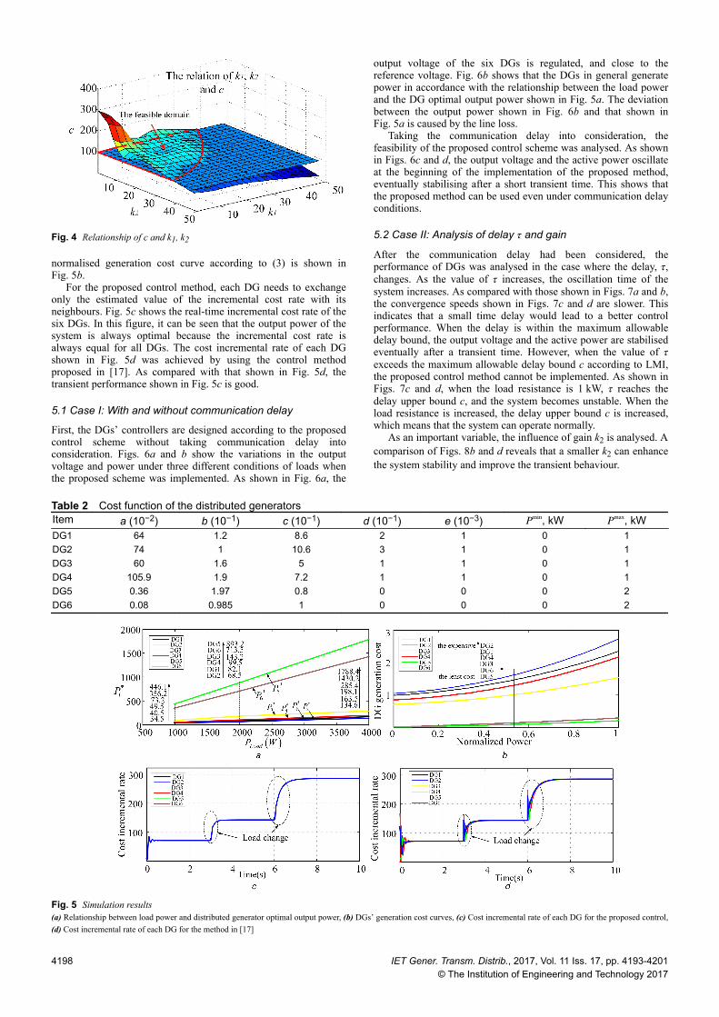
normalised generation cost curve according to (3) is shown inFig. 5b.
For the proposed control method, each DG needs to exchangeonly the estimated value of the incremental cost rate with itsneighbours. Fig. 5c shows the real-time incremental cost rate of thesix DGs. In this figure, it can be seen that the output power of thesystem is always optimal because the incremental cost rate isalways equal for all DGs. The cost incremental rate of each DGshown in Fig. 5d was achieved by using the control methodproposed in [17]. As compared with that shown in Fig. 5d, thetransient performance shown in Fig. 5c is good.
5.1 Case I: With and without communication delay
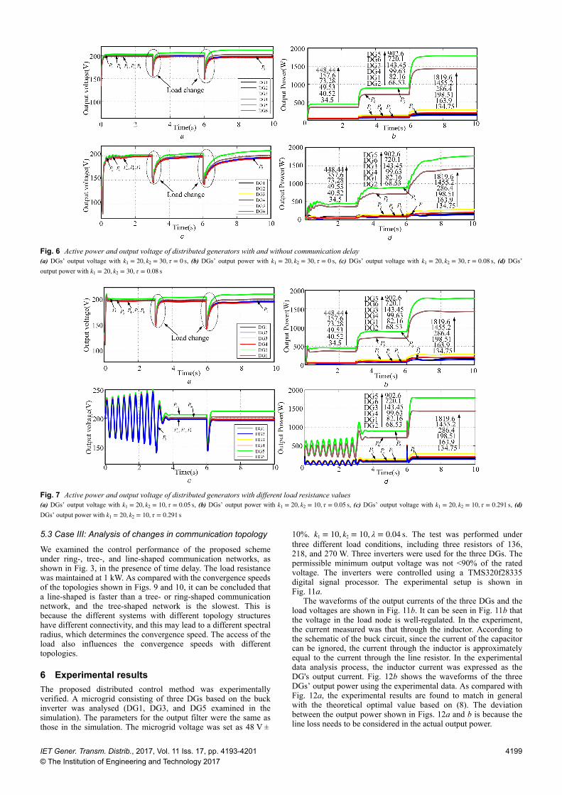
First, the DGs’ controllers are designed according to the proposedcontrol scheme without taking communication delay intoconsideration. Figs. 6a and b show the variations in the outputvoltage and power under three different conditions of loads whenthe proposed scheme was implemented. As shown in Fig. 6a, the
output voltage of the six DGs is regulated, and close to thereference voltage. Fig. 6b shows that the DGs in general generatepower in accordance with the relationship between the load powerand the DG optimal output power shown in Fig. 5a. The deviationbetween the output power shown in Fig. 6b and that shown inFig. 5a is caused by the line loss.
Taking the communication delay into consideration, thefeasibility of the proposed control scheme was analysed. As shownin Figs. 6c and d, the output voltage and the active power oscillateat the beginning of the implementation of the proposed method,eventually stabilising after a short transient time. This shows thatthe proposed method can be used even under communication delayconditions.
5.2 Case II: Analysis of delay τ and gain
After the communication delay had been considered, theperformance of DGs was analysed in the case where the delay, τ,changes. As the value of τ increases, the oscillation time of thesystem increases. As compared with those shown in Figs. 7a and b,the convergence speeds shown in Figs. 7c and d are slower. Thisindicates that a small time delay would lead to a better controlperformance. When the delay is within the maximum allowabledelay bound, the output voltage and the active power are stabilisedeventually after a transient time. However, when the value of τexceeds the maximum allowable delay bound c according to LMI,the proposed control method cannot be implemented. As shown inFigs. 7c and d, when the load resistance is 1 kW, τ reaches thedelay upper bound c, and the system becomes unstable. When theload resistance is increased, the delay upper bound c is increased,which means that the system can operate normally.
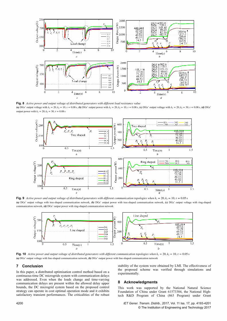
As an important variable, the influence of gain k2 is analysed. Acomparison of Figs. 8b and d reveals that a smaller k2 can enhancethe system stability and improve the transient behaviour.
Table 2 Cost function of the distributed generatorsItem a (10−2) b (10−1) c (10−1) d (10−1) e (10−3) Pmin, kW Pmax, kWDG1 64 1.2 8.6 2 1 0 1DG2 74 1 10.6 3 1 0 1DG3 60 1.6 5 1 1 0 1DG4 105.9 1.9 7.2 1 1 0 1DG5 0.36 1.97 0.8 0 0 0 2DG6 0.08 0.985 1 0 0 0 2
Fig. 4 Relationship of c and k1, k2
Fig. 5 Simulation results(a) Relationship between load power and distributed generator optimal output power, (b) DGs’ generation cost curves, (c) Cost incremental rate of each DG for the proposed control,(d) Cost incremental rate of each DG for the method in [17]
4198 IET Gener. Transm. Distrib., 2017, Vol. 11 Iss. 17, pp. 4193-4201
© The Institution of Engineering and Technology 2017
5.3 Case III: Analysis of changes in communication topology
We examined the control performance of the proposed schemeunder ring-, tree-, and line-shaped communication networks, asshown in Fig. 3, in the presence of time delay. The load resistancewas maintained at 1 kW. As compared with the convergence speedsof the topologies shown in Figs. 9 and 10, it can be concluded thata line-shaped is faster than a tree- or ring-shaped communicationnetwork, and the tree-shaped network is the slowest. This isbecause the different systems with different topology structureshave different connectivity, and this may lead to a different spectralradius, which determines the convergence speed. The access of theload also influences the convergence speeds with differenttopologies.
6 Experimental resultsThe proposed distributed control method was experimentallyverified. A microgrid consisting of three DGs based on the buckinverter was analysed (DG1, DG3, and DG5 examined in thesimulation). The parameters for the output filter were the same asthose in the simulation. The microgrid voltage was set as 48 V ±
10%. k1 = 10, k2 = 10, λ = 0.04 s. The test was performed underthree different load conditions, including three resistors of 136,218, and 270 W. Three inverters were used for the three DGs. Thepermissible minimum output voltage was not <90% of the ratedvoltage. The inverters were controlled using a TMS320f28335digital signal processor. The experimental setup is shown inFig. 11a.
The waveforms of the output currents of the three DGs and theload voltages are shown in Fig. 11b. It can be seen in Fig. 11b thatthe voltage in the load node is well-regulated. In the experiment,the current measured was that through the inductor. According tothe schematic of the buck circuit, since the current of the capacitorcan be ignored, the current through the inductor is approximatelyequal to the current through the line resistor. In the experimentaldata analysis process, the inductor current was expressed as theDG's output current. Fig. 12b shows the waveforms of the threeDGs’ output power using the experimental data. As compared withFig. 12a, the experimental results are found to match in generalwith the theoretical optimal value based on (8). The deviationbetween the output power shown in Figs. 12a and b is because theline loss needs to be considered in the actual output power.
Fig. 6 Active power and output voltage of distributed generators with and without communication delay(a) DGs’ output voltage with k1 = 20, k2 = 30, τ = 0 s, (b) DGs’ output power with k1 = 20, k2 = 30, τ = 0 s, (c) DGs’ output voltage with k1 = 20, k2 = 30, τ = 0.08 s, (d) DGs’output power with k1 = 20, k2 = 30, τ = 0.08 s
Fig. 7 Active power and output voltage of distributed generators with different load resistance values(a) DGs’ output voltage with k1 = 20, k2 = 10, τ = 0.05 s, (b) DGs’ output power with k1 = 20, k2 = 10, τ = 0.05 s, (c) DGs’ output voltage with k1 = 20, k2 = 10, τ = 0.291 s, (d)DGs’ output power with k1 = 20, k2 = 10, τ = 0.291 s
IET Gener. Transm. Distrib., 2017, Vol. 11 Iss. 17, pp. 4193-4201© The Institution of Engineering and Technology 2017
4199
7 ConclusionIn this paper, a distributed optimisation control method based on acontinuous-time DC microgrids system with communication delayswas addressed. Even when the loads change and time-varyingcommunication delays are present within the allowed delay upperbounds, the DC microgrid system based on the proposed controlstrategy can operate in cost optimal operation mode and it exhibitssatisfactory transient performances. The criticalities of the robust
stability of the system were obtained by LMI. The effectiveness ofthe proposed scheme was verified through simulations andexperimentally.
8 AcknowledgmentsThis work was supported by the National Natural ScienceFoundation of China under Grant 61573384, the National High-tech R&D Program of China (863 Program) under Grant
Fig. 8 Active power and output voltage of distributed generators with different load resistance value(a) DGs’ output voltage with k1 = 20, k2 = 10, τ = 0.08 s, (b) DGs’ output power with k1 = 20, k2 = 10, τ = 0.08 s, (c) DGs’ output voltage with k1 = 20, k2 = 30, τ = 0.08 s, (d) DGs’output power with k1 = 20, k2 = 30, τ = 0.08 s
Fig. 9 Active power and output voltage of distributed generators with different communication topologies when k1 = 20, k2 = 10, τ = 0.05 s(a) DGs’ output voltage with tree-shaped communication network, (b) DGs’ output power with tree-shaped communication network, (c) DGs’ output voltage with ring-shapedcommunication network, (d) DGs’ output power with ring-shaped communication network
Fig. 10 Active power and output voltage of distributed generators with different communication topologies when k1 = 20, k2 = 10, τ = 0.05 s(a) DGs’ output voltage with line-shaped communication network, (b) DGs’ output power with line-shaped communication network
4200 IET Gener. Transm. Distrib., 2017, Vol. 11 Iss. 17, pp. 4193-4201© The Institution of Engineering and Technology 2017

2015AA050604, Central South University innovation-drivenproject and Natural Science Foundation of Hunan Province ofChina under Grant 2016JJ1019.
9 References[1] Baran, M., Mahajan, N.: ‘DC distribution for industrial systems: opportunities
and challenges’, IEEE Trans. Ind. Electron., 2003, 39, (6), pp. 1596–1601[2] Su, M., Liu, Z., Sun, Y.,, et al.: ‘Stability analysis and stabilization methods of
DC microgrid with multiple parallel-connected DC-DC converters loaded byCPLs’, IEEE Trans. Smart Grid, 2016, PP, (99), pp. 1–1, DOI: 10.1109/TSG.2016.2546551
[3] Han, H., Hou, X., Yang, J.,, et al.: ‘Review of power sharing control strategiesfor islanding operation of AC microgrids’, IEEE Trans. Smart Grid, 2016, 7,(1), pp. 200–215
[4] Olivares, D., Canizares, C., Kazerani, M.: ‘A centralized optimal energymanagement system for microgrids’. Proc. IEEE Power Energy SocietyGeneral Meeting, 2011
[5] Tan, K., Peng, X., So, P.,, et al.: ‘Centralized control for parallel operation ofdistributed generation inverters in microgrids’, IEEE Trans. Smart Grid,2012, 3, (4), pp. 1977–1987
[6] Ahn, C., Peng, H.: ‘Decentralized voltage control to minimize distributionpower loss of microgrid’, IEEE Trans. Smart Grid, 2013, 4, (3), pp. 1297–1304
[7] Nutkani, I., Loh, P., Wang, P.,, et al.: ‘Dcentralized economical dispatchscheme with online power reserve for microgrid’, IEEE Trans. Smart Grid,2017, 8, (1), pp. 139–148
[8] Huang, P., Liu, P., Xiao, W.,, et al.: ‘A novel droop-based average voltagesharing control strategy for DC microgrids’, IEEE Trans. Smart Grid, 2015, 6,(3), pp. 1096–1106
[9] Sun, Y., Hou, X., Yang, J.,, et al.: ‘New perspectives on droop control in ACmicrogrid’, IEEE Trans. Ind. Electron., 2017, 64, (17), pp. 5741–5745
[10] Nutkani, I., Loh, P., Wang, P.,, et al.: ‘Autonomous droop scheme withreduced generation cost’, IEEE Trans. Ind. Electron., 2014, 61, (12), pp.6803–6811
[11] Nutkani, I., Loh, P., Wang, P.,, et al.: ‘Cost-based droop scheme for DCmicrogrid’. Energy Conversion Congress and Exposition, 2014
[12] Lee, C.: ‘A new droop control method for the autonomous operation ofdistributed energy resource interface converters’, IEEE Trans. PowerElectron., 2013, 28, (4), pp. 1980–1993
[13] Lu, J., Zhang, Y., Long, J.,, et al.: ‘A novel virtual impedance method fordroop controlled parallel UPS inverters with wireless control’. ITEC Asia-Pacific, 2014
[14] Zhang, Z., Chow, M.: ‘Convergence analysis of the incremental costconsensus algorithm under different communication network topologies in asmart grid’, IEEE Trans. Power Syst., 2012, 27, (4), pp. 1761–1768
[15] Yang, S., Tan, S., Xu, J.: ‘Consensus based approach for economic dispatchproblem in a smart grid’, IEEE Trans. Power Syst., 2013, 28, (4), pp. 4416–4426
[16] Zhang, W., Liu, W., Wang, X.,, et al.: ‘Online optimal generation controlbased on constrained distributed gradient algorithm’, IEEE Trans. PowerSyst., 2015, 30, (1), pp. 35–45
[17] Moayedi, S., Davoudi, A.: ‘Unifying distributed dynamic optimization andcontrol of islanded DC microgrids’, IEEE Trans. Power Electron., 2017, 32,(3), pp. 2329–2346
[18] Wang, Z., Wu, W., Zhang, B.: ‘A distributed control method with minimumgeneration cost for DC microgrids’, IEEE Trans. Energy Convers., 2016, 31,(4), pp. 1462–1470
[19] Nasirian, V., Davoudi, A., Lewis, F.: ‘Distributed adaptive droop control forDC distribution system’, IEEE Trans. Energy Convers., 2014, 29, (4), pp.944–956
[20] Nasirian, V., Moayedi, S., Davoudi, A.,, et al.: ‘Distributed cooperativecontrol of DC microgrid’, IEEE Trans. Power Electron., 2015, 30, (4), pp.2288–2303
[21] Zhou, Y., Huang, Z., Liu, W.,, et al.: ‘A distributed ESO based cooperativecurrent-sharing strategy for parallel charging systems under disturbances’.Energy Conversion Congress and Exposition, 2016, pp. 1–7
[22] Wang, F., Liang, J., Huang, T.: ‘Synchronisation of stochastic delayed multi-agent systems with uncertain communication links and directed topologies’,IET Control Theory Appl., 2016, 11, (1), pp. 90–100
[23] Xiang, J., Li, Y., Wei, W.,, et al.: ‘Synchronisation of linear continuous multi-agent systems with switching topology and communication delay’, IETControl Theory Appl., 2014, 8, (14), pp. 1415–1420
[24] Sun, Y., Wang, L.: ‘Consensus of multi-agent systems in directed networkswith nonuniform time-varying delays’, IEEE Trans. Autom. Control, 2009,54, (7), pp. 1607–1613
[25] Carli, R., Chiuso, A., Schenato, L.,, et al.: ‘Optimal synchronization fornetworks of noisy double integrators’, IEEE Trans. Autom. Control, 2011, 56,(5), pp. 1146–1152
[26] Nedic, A., Ozdaglar, A., Parrilo, P.A.: ‘Constrained consensus andoptimization in multi-agent networks’, IEEE Trans. Autom. Control, 2010, 55,(4), pp. 922–938
[27] Chen, G., Zhao, Z.: ‘Delay effects on consensus-based distributed economicdispatch algorithm in microgrid’, IEEE Trans. Power Syst., 2016, PP, (99),pp. 1–1, DOI: 10.1109/TPWRS.2017.2702179
[28] Chen, G., Wen, C., Mao, J.,, et al.: ‘Distributed economic dispatch for smartgrids with random wind power’, IEEE Trans. Smart Grid, 2016, 7, (3), pp.1572–1583
[29] Hetzer, J., Yu, D., Bhattarai, K.: ‘An economic dispatch modeling cooperatingwind power’, IEEE Trans. Energy Convers., 2008, 23, (2), pp. 603–611
[30] Sun, Y., Zhang, G., Xu, W.,, et al.: ‘A harmonically coupled admittancematrix model for AC/DC converters’, IEEE Trans. Power Syst., 2007, 22, (4),pp. 1574–1582
[31] He, Y., Wang, Q., Xie, L.,, et al.: ‘Further improvement of free-weightingmatrices technique for systems with time-varying delay’, IEEE Trans. Autom.Control, 2007, 52, (2), pp. 293–299
Fig. 11 Waveforms of the output currents of the three DGs and the load voltages(a) Experimental setup, (b) Output current and load voltage waveforms
Fig. 12 The theoretical values and the experimental values of the three DGs output power(a) Relationship between load power and distributed generator optimal output power, (b) Output power waveforms with the experimental data
IET Gener. Transm. Distrib., 2017, Vol. 11 Iss. 17, pp. 4193-4201© The Institution of Engineering and Technology 2017
4201