ieee transactions on smart grid, vol. 4, no. 1, … · in matlab simulink. ... this work was...
TRANSCRIPT

IEEE TRANSACTIONS ON SMART GRID, VOL. 4, NO. 1, MARCH 2013 419
Modified Dynamic Phasor Estimation Algorithm forthe Transient Signals of Distributed Generators
Dong-Gyu Lee, Sang-Hee Kang, and Soon-Ryul Nam, Member, IEEE
Abstract—In this paper, a modified dynamic phasor estimationmethod for protection relays is proposed to calculate the dynamicphasor of a fundamental frequency component with time-variantamplitude. The fault current is assumed to be the combination of adecaying dc offset, a decaying fundamental frequency componentand harmonics with constant amplitude. The exponential functionsof the decaying dc offset and fundament frequency component arereplaced by Taylor series. Then, the LS (Least Square) techniqueis used to estimate the magnitudes and the time constants of de-caying components. The performance of the algorithm is evaluatedby using computer-simulated signals based on simple equationsand fault current signals collected from DFIG wind farm modelin MATLAB Simulink. The test results indicate that the proposedalgorithm can accurately estimate the decaying amplitude and thetime constant of the fundamental frequency component.
Index Terms—Distributed generators, modified dynamic phasor,phasor estimation, time-variant fault current.
I. INTRODUCTION
N OWADAYS, there is much interest in connecting varioussources of electrical energy, typically described as dis-
tributed energy resources (DERs), to electric power systems.Much of this interest is due to the demands of clean energy, highreliability, and enhanced power quality. DERs offer a variety ofpossibilities for energy conversion and electric power genera-tion. Various energy sources and converters are used to generateelectricity through PV arrays, wind turbines, fuel cells, micro-turbines, conventional diesel and natural gas reciprocating en-gines, gas-fired turbines, and energy storage technologies [1].However, the installation of DERs in the power systems will
create operating conflicts. The potential problems from the in-stallation of DERs, such as changes in coordination of protec-tive devices, nuisance trip, safety degradation and changes inthe reach of protective relays, were discussed in [2], [3]. Adap-tive protection schemes were proposed for distribution systemsconnected with wind generators [4], [5]. The protection of trans-mission lines connected to wind farms was discussed in [6]. Anadaptive setting method was proposed for the distance relay to
Manuscript received November 27, 2012; accepted December 09, 2012. Dateof publication December 28, 2012; date of current version February 27, 2013.This work was supported by the Basic Science Research Program through theNational Research Foundation of Korea (NRF) funded by the Ministry of Ed-ucation, Science and Technology (MEST) (2012 R1A1 A204 2252). Paper no.TSG-00824-2012.D.-G. Lee is with the Power and Industrial Systems R&D Center, Hyosung
Corporation, Anyang, Korea (e-mail: [email protected]).S.-H. Kang and S.-R. Nam are with the Department of Electrical Engineering,
Myongji University, Yongin 449-728, Korea (e-mail: [email protected], [email protected]).Color versions of one or more of the figures in this paper are available online
at http://ieeexplore.ieee.org.Digital Object Identifier 10.1109/TSG.2012.2233772
protect a transmission line connected to a wind farm [7]. All ofthese kinds of adaptive protection methods as well as traditionalprotection algorithms are based on estimating the phasors of thevoltage and current signals.Most of digital relays adopt discrete Fourier transform
(DFT)-based algorithms to estimate the phasors of a voltagesignal and a current signal. A fault current in the conventionalpower system is generally considered as the combination ofan exponentially decaying dc component and sinusoidal com-ponents with the time-invariant amplitude. The time-variantamplitude of the sinusoidal component is only consideredon pickup settings of generator protection relays for themulti-phase faults involving synchronous generators. It is be-cause the time constant of the decaying sinusoidal componentis long enough to not produce a significant error on the resultof DFT. In order to estimate the accurate current phasor usingDFT, the dc-offset should be removed from the fault currentsignal. For this purpose, several techniques have been proposedto reduce or remove the adverse effect of the decaying dccomponent on the result of phasor estimation using DFT-basedmethod [8]–[12].However, the fault currents delivered from distributed gen-
erators, especially small synchronous generators or doubly-fedinduction generators (DFIG) directly connected to power sys-tems have time-variant characteristics of the sinusoidal compo-nents with small time constants. These make the phasor estima-tion task more challenging since most algorithms to estimate thephasors of voltage and current are developed by presuming thetime-invariant amplitude of a sinusoidal signal at a frequency.A new concept of the phasor estimation method referred to asdynamic phasor was proposed for estimating the time-variantamplitude and phase of a sinusoidal component during powersystem oscillation [13]. This method, however, is not suitablefor applying to protection relays because a decaying dc compo-nent is not considered.In this paper, a modified dynamic phasor estimation method
for protection relays is proposed to calculate a dynamic phasorof a fundamental frequency component with time-variant am-plitude. The fault current is assumed to be the combination of adecaying dc offset, a decaying fundamental frequency compo-nent and harmonics with constant amplitude. The exponentialfunctions of the decaying dc offset and fundament frequencycomponent are replaced by Taylor series. The LS (Least Square)technique is used to estimate the amplitudes and the time con-stants of the decaying components.The performance of the proposed algorithm is evaluated by
using computer-simulated signals based on simple equationsand fault current signals generated using DFIGwind farmmodelin MATLAB Simulink. To demonstrate the performance of theproposed algorithm, the test results are compared to those of a
1949-3053/$31.00 © 2012 IEEE

420 IEEE TRANSACTIONS ON SMART GRID, VOL. 4, NO. 1, MARCH 2013
DFT-based method which is called PS (partial sum)-based DFT[9]. The test results indicate that the proposed algorithm can ac-curately estimate the decaying amplitude and the time constantof the fundamental frequency component.
II. CHARACTERISTICS OF SHORT-CIRCUIT CURRENTS
A. Short Circuit Currents of a Synchronous Generator
It is well known that the behavior of synchronous generatorsduring fault conditions is typically quantified by three reactancevalues: subtransient reactance , which addresses generatorbehavior during the early time domain of a fault; transient re-actance , which addresses generator behavior during themedium time domain of the fault; and synchronous reactance
, which addresses generator behavior during the long timedomain of the fault. The duration of the time domains is ad-dressed by two time constants: subtransient time constantand transient time constant [1]. A fault current of A-phasecan be expressed by an exponential equation with generator ter-minal voltage magnitude , all three generator reactancesand both time constants as follows:
(1)
B. Short Circuit Currents of a DFIG
In this section, the equation for the short-circuit current of aDFIG determined in [14] is briefly introduced.Over the last couple of decades, several researches have been
done to analysis the short-circuit current of induction generator[14]–[16]. The result formulas to describe the short circuit cur-rent are slightly different between each research. It is becausethe short-circuit behavior of an induction machine is stronglydependent on the machine and their controller characteristics.All of the researches, however, indicate that the short-circuitcurrent of an induction generator consists of an ac componentwith a frequency which is equal to the rotor speed and a dc com-ponent. These two components decrease exponentially.When a three-phase fault occurs at the stator terminal of a
DFIG, the short-circuit current of A-phase is
(2)
where is the magnitude of the stator voltage, is the tran-sient stator reactance, and are the transient time constantsfor the damping of the dc component in stator and rotor, isthe mutual inductance between stator and rotor, is the rotorinductance, and is the synchronous rotational speed.Although (1) and (2) are to describe the A-phase current for
the three-phase fault at the generator terminal, these equationsare also useful to understand a fault current supplied from dis-tributed generations when a fault occurs in a neighboring dis-tribution feeder or a transmission line. The fault current deliv-ered from distributed generators during grid fault conditions hasa time-variant characteristic of the sinusoidal component with
Fig. 1. Example of a short-circuit current with time-variant amplitude and itseffect on DFT-based algorithms. (a) Short-circuit current. (b) Estimated ampli-tude.
a time constant. It may result in some significant error in thephasor value estimated by DFT. Fig. 1 shows an example waveform of the fault current which consists of a decaying funda-mental frequency component and a decaying dc offset compo-nent. It also shows the effect of decaying amplitude character-istic of the sinusoidal component on the result of phasor estima-tion using DFT-based method. DFT is simple and easily to beimplemented, but the output of DFT contains some errors dueto both the decaying dc offset component and the decaying si-nusoidal component. Since PS-based DFT is only designed toremove the adverse influence of the decaying dc offset, it doesnot cope effectively with the decaying sinusoidal component.Accordingly, the decaying amplitude characteristic of the sinu-soidal component causes decrease and fluctuation in the ampli-tude value of the estimated phasor using a method assuming theconstant amplitude of a sinusoidal signal at a frequency suchas DFT. The estimated phasor value is smaller than the desiredvalue, then it may result in the failure to trip or delayed opera-tion of protection relays.
III. MODIFIED DYNAMIC PHASOR ESTIMATION ALGORITHM
As refer to (1) and (2), the fault current delivered from dis-tributed generators can be considered as the sum of a decayingdc offset component, a decaying fundamental frequency com-ponent and harmonics with constant amplitude. At time ,this wave form can be mathematically expressed as follows:
(3)
where and are the amplitude and the time constant of thedecaying dc component, is the fundamental frequency of thesystem, and are the constant amplitude, thedecaying amplitude, the phase angle and the time constant ofthe decaying fundamental frequency component, respectively,

LEE et al.: MODIFIED DYNAMIC PHASOR ESTIMATION ALGORITHM FOR THE TRANSIENT SIGNALS OF DISTRIBUTED GENERATORS 421
and are the amplitude and the phase angle of the thharmonic component, is the highest order of the harmoniccomponent present in the signal.It is possible to expand by using the Taylor series as
follows:
(4)
Higher order harmonics can be blocked by the signal con-ditioning equipment such as an analog low-pass filter. Usingthe Taylor series expansion in (4) and assuming that harmoniccomponents higher than fifth order are effectively blocked by alow-pass filter and that even harmonics are hardly present in thepower system signals, (3) can be represented as
(5)
where
If the current is sampled with a specific time interval, , (5)can be expanded to each current sample and the equations canbe written in the matrix forms as follows:
(6)
The elements of the matrix [A] depend on the time referencesand the sampling interval and those can be predetermined in anoff-line mode. The matrix [i] made up of the sampled currentdata is also known.If the number of current samples, m, is greater than 13, the
number of unknown variables, the matrix [X] composed of theunknown variables can be determined by using the LS (LeastSquare) technique as follows:
(7)
Finally, the dynamic phasor of the fundamental frequencycomponent can be obtained as follows:
(8)
IV. PERFORMANCE EVALUATION
The performance of the proposed algorithm is evaluated byusing computer-simulated signals based on simple equations
Fig. 2. Results for the Case 1 with condition. (a) Cycle,Cycle. (b) Cycle, Cycle.
Fig. 3. Results for the Case 1 with condition. (a)Cycle. (b) Cycle.
and fault current signals generated by using DFIG wind farmmodel in MATLAB Simulink. To demonstrate the performanceof the proposed algorithm, the test results are compared to thoseof PS(partial sum)-based DFT [9].
A. Using Computer-Simulated Signals
In order to demonstrate the performance of the proposed al-gorithm, computer-simulated signals are used first for the testunder various signal conditions. In this performance test, thesampling frequency is set to 3 840 Hz, i.e., 64 samples per cyclein a 60 Hz system and the number of current samples, m, is setto the number of samples per cycle.Case 1. Constant Amplitude Decaying Amplitude: In this
case, the constant amplitude of the fundamental frequency com-ponent is greater than the decaying amplitude. The test signalused in this case is assumed as follows:
(9)
Figs. 2 and 3 show the input signals for Case 1 and the esti-mated amplitudes of the fundamental frequency component by
422 IEEE TRANSACTIONS ON SMART GRID, VOL. 4, NO. 1, MARCH 2013
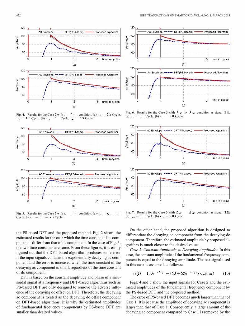
Fig. 4. Results for the Case 2 with condition. (a) Cycle,Cycle. (b) Cycle, Cycle.
Fig. 5. Results for the Case 2 with condition. (a)Cycle. b) Cycle.
the PS-based DFT and the proposed method. Fig. 2 shows theestimated results for the case which the time constant of ac com-ponent is differ from that of dc component. In the case of Fig. 3,the two time constants are same. From these figures, it is easilyfigured out that the DFT-based algorithm produces some errorif the input signals contains the exponentially decaying ac com-ponent and the error is increased when the time constant of thedecaying ac component is small, regardless of the time constantof dc component.DFT is based on the constant amplitude and phase of a sinu-
soidal signal at a frequency and DFT-based algorithms such asPS-based DFT are only designed to remove the adverse influ-ence of the decaying dc offset on DFT. Therefore, the decayingac component is treated as the decaying dc offset componenton DFT-based algorithms. It is why the estimated amplitudesof fundamental frequency components by PS-based DFT aresmaller than desired values.
Fig. 6. Results for the Case 3 with condition as signal (11).(a) Cycle. (b) Cycle.
Fig. 7. Results for the Case 3 with condition as signal (12).(a) Cycle. (b) Cycle.
On the other hand, the proposed algorithm is designed todifferentiate the decaying ac component from the decaying dccomponent. Therefore, the estimated amplitude by proposed al-gorithm is much closer to the desired value.Case 2. Constant Amplitude Decaying Amplitude: In this
case, the constant amplitude of the fundamental frequency com-ponent is equal to the decaying amplitude. The test signal usedin this case is assumed as follows:
(10)
Figs. 4 and 5 show the input signals for Case 2 and the esti-mated amplitudes of the fundamental frequency component bythe PS-based DFT and the proposed method.The error of PS-based DFT becomes much larger than that of
Case 1. It is because the amplitude of decaying ac component islarger than that of Case 1. Consequently, a large amount of thedecaying ac component compared to Case 1 is removed by the

LEE et al.: MODIFIED DYNAMIC PHASOR ESTIMATION ALGORITHM FOR THE TRANSIENT SIGNALS OF DISTRIBUTED GENERATORS 423
Fig. 8. Diagram of the model system.
function of PS-based DFT to eliminate the effect of the decayingdc offset.On the other hand, the outputs of the proposed method are
still much closer to the desired value.Case 3. Decaying dc offset component 0: In this case, the
zero dc offset component is considered. The test signals used inthis case are assumed as follows:
(11)
(12)
Figs. 6 and 7 show the input signals, the estimated amplitudesof the fundamental frequency component by the PS-based DFTand the proposed method for Case 3. The results for this casedo not much differ from the results for Case 1 and 2. Becausethe error of the PS-based DFT is caused by the decaying accomponent, regardless of the existence of the decaying dc offsetcomponent.
B. Using Fault Current Signals Generated by DFIG WindFarm Model in MATLAB Simulink
In this section, the performance evaluation of the proposed al-gorithm by using fault current signals generated by DFIG windfarm model in MATLAB Simulink is described.During the normal operation, two wind farms each consisting
of six units of 1.5 MW wind turbines supply totally 18 MWpower to the load through 22.9 kV distribution feeders, as shownin Fig. 8. The basic wind farm and DFIG model were takenfrom [17]. Each wind turbine using a doubly-fed induction gen-erator consists of a wound rotor induction generator and anAC/DC/AC IGBT-based PWM converter. The stator windingis connected directly to the 60 Hz grid while the rotor is fedat variable frequency through the AC/DC/AC converter. In thesimulations, the wind speed is maintained constant at 15 m/s.The control system uses a torque controller in order to maintainthe rotor speed at 1.2 pu. The reactive power produced by thewind turbine is regulated at 0 Mvar.Double line to ground (A-B-ground) faults with fault resis-
tances of 0 and 10 were applied on the 154 kV transmissionline at the distance of 16 km from L bus. The fault currents aremeasured at L bus.
Fig. 9. A-phase current and amplitude estimation results .(a) A-phase current measured at the relaying point. (b) Estimated amplitude.
For this performance test, the sampling frequency is set to 3840 Hz, i.e., 64 samples per cycle in a 60 Hz system. The inputsignal is preprocessed by a 2nd order Butterworth low-pass filterwith the gain of 0.1 at the stop-band cutoff frequency of 480Hz in order to remove harmonics and to prevent aliasing errors.The number of current samples is set to 1.75 times the numberof samples per cycle for stable outputs.Figs. 9 and 10 show the wave forms of the A-phase currents
measured at the relaying point and the estimated amplitudes ofthe fundamental frequency components by the PS-based DFTand the proposed algorithm. In this performance test, the timedomain response of the PS-based DFT is faster than that of theproposed algorithm. It is because the PS-based DFT uses onecycle sample data, but the proposed algorithm uses 1.75 cyclesample data.However, the estimated amplitudes by PS-based DFT are
much smaller than the output of the proposed algorithm. There-fore, a protection relay only adopting the DFT-based algorithmto estimate the phasor of the fundamental frequency componentmay fail to trip or may have unnecessary time delay. If the

424 IEEE TRANSACTIONS ON SMART GRID, VOL. 4, NO. 1, MARCH 2013
Fig. 10. A-phase current and amplitude estimation results .(a) A-phase current measured at the relaying point. (b) Estimated amplitude.
proposed algorithm is applied to a protection relay, those kindsof mal-operation are prevented. Even in the worst case, theoperation of the protective relay is delayed three quarters cyclemore because the data window is 1.75 times the number ofsamples per cycle.
V. CONCLUSION
This paper proposes a modified dynamic phasor estimationmethod to estimate the dynamic phasor of the fundamental fre-quency component with time-variant amplitude. The exponen-tial functions of the decaying dc offset and fundament frequencycomponent is replaced by Taylor series and the least square tech-nique is used to estimate the amplitudes and the time constantsof the decaying components.The performance of the proposed algorithm is evaluated by
using computer-simulated signals based on simple equationsand fault current signals generated by using DFIG wind farmmodel in MATLAB Simulink. The test results indicate that theproposed algorithm can accurately estimate the decaying ampli-tude and the time constant of the fundamental frequency com-ponent.
REFERENCES
[1] IEEE Standard for Interconnecting Distributed Resources With Elec-tric Power Systems, IEEE Application Guide for IEEE Std 1547™,IEEE Standard 1547.2-2008, Dec. 2008.
[2] R. C. Dugan and T. E. McDermott, “Operating conflicts for distributedgeneration on distribution systems,” in Proc. 2001 Rural ElectricPower Conf., pp. A3/1–A3/6.
[3] R. C. Dugan and S. K. Price, “Issues for distributed generation in theUS,” in Proc. 2002 IEEE Power Engineering Society Winter Meeting,vol. 1, pp. 121–126.
[4] S. I. Jang, J. H. Choi, J. W. Kim, and D.M. Choi, “An adaptive relayingfor the protection of a wind farm interconnected with distribution net-works,” in Proc. 2003 IEEE PES Transmission and Distribution Conf.Exhibition, vol. 1, pp. 296–302.
[5] S. M. Brahma and A. A. Girgis, “Development of adaptive protectionschemes for distribution systems with high penetration of distributiongeneration,” IEEE Trans. Power Del., vol. 19, no. 1, pp. 56–63, Jan.2004.
[6] D. Hornak and N. H. J. Chau, “Green power-wind generated protectionand control considerations,” in Proc. IEEE 57th Annual Conf. Protec-tive Relay Eng., 2004, pp. 110–131.
[7] A. K. Pradhanand and G. Joos, “Adaptive distance relay setting forlines connecting wind farms,” IEEE Trans. Energy Conv., vol. 22, no.1, pp. 206–213, Mar. 2007.
[8] G. Benmouyal, “Removal of DC offset in current waveforms usingdigital mimic filtering,” IEEE Trans. Power Del., vol. 10, no. 2, pp.621–630, Apr. 1995.
[9] J.-C. Gu and S.-L. Yu, “Removal of DC offset in current and voltagesignals using a novel Fourier filter algorithm,” IEEE Trans. Power Del.,vol. 15, no. 1, pp. 73–79, Jan. 2000.
[10] S.-R. Nam, S.-H. Kang, and J.-K. Park, “An analytic method formeasuring accurate fundamental frequency components,” IEEE Trans.Power Del., vol. 17, no. 2, pp. 405–411, Apr. 2002.
[11] Y. Guo, M. Kezunovic, and D. Chen, “Simplified algorithms for re-moval of the effect of exponentially decaying DC offset on the Fourieralgorithm,” IEEE Trans. Power Del., vol. 18, no. 3, pp. 711–717, Jul.2003.
[12] S.-H. Kang, D.-G. Lee, S.-R. Nam, P. A. Crossley, and Y.-C. Kang,“Fourier transform-based modified phasor estimation method immuneto the effect of the DC offsets,” IEEE Trans. Power Del., vol. 24, no.3, pp. 1104–1111, Jul. 2009.
[13] J. A. de la O Serna, “Dynamic phasor estimates for power systems os-cillations,” IEEE Trans. Instrum. Meas., vol. 56, no. 5, pp. 1648–1657,Oct. 2007.
[14] J. Morren and S.W. H. de Haan, “Short-circuit current of wind turbineswith doubly fed induction generator,” IEEE Trans. Energy Conv., vol.22, no. 1, pp. 174–180, Mar. 2007.
[15] M. S. Vicatos and J. A. Tegopoulos, “Transient state analysis of adoubly fed induction generator under three phase short circuit,” IEEETrans. Energy Conv., vol. 6, no. 1, pp. 62–68, 1991.
[16] T. Senjyu, N. Sueyoshi, K. Uezato, and H. Fujita, “Transient currentanalysis of induction generator for wind power generating system,” inProc. 2002 IEEE PES Transmission and Distribution Conf. Exhibition,vol. 3, pp. 1647–1652.
[17] Matlab User’s Guide and Reference,Matlab/Simulink/SimPpowerSys-tems Ver.7.3.
Dong-Gyu Lee received the B.S. and M.S. degreesfrom Myongji University, Yongin, Korea, in 2002and 2004, respectively. He is now studying for thePh.D. degree at Myongji University.He is a principal researcher of Power and Industrial
Systems R&D Center, Hyosung Corporation, Korea.His main research interests are power system protec-tion.
Sang-Hee Kang (S’90–M’93) received the B.S.,M.S., and Ph.D. degrees from Seoul NationalUniversity, Seoul, Korea, in 1985, 1987, and 1993,respectively.He is a Professor at Myongji University, Korea.
He was a visiting fellow and a visiting scholar at theUniversity of Bath, U.K., in 1991 and 1999. He hasalso been with Next-generation Power TechnologyCenter, Korea, since 2001. He was an honorary aca-demic visitor at the University of Manchester, U.K.,in 2007. His research interest is in developing digital
protection systems for power systems using digital signal processing techniques.
Soon-Ryul Nam (S’96–M’02) received the B.S.,M.S., and Ph.D. degrees from Seoul NationalUniversity, Seoul, Korea, in 1996, 1998, and 2002,respectively.Currently, he is an Assistant Professor with
Myongji University, Yongin, Korea. He was withHoysung Corp., Korea, from 2002 to 2005 andwas a Research Professor with Myongji Universityfrom 2005 to 2007. He was a Postdoctoral ResearchAssociate with Texas A&M University, CollegeStation, in 2007 and an Assistant Professor with
Chonnam National University, Kwangju, Korea, from 2007 to 2009. Hisresearch interests are the protection, control, and automation of power systems.