ieee 802.11 & 802 - umd department of computer science · contents 802.11 and 802.11b...
TRANSCRIPT


Contents802.11 and 802.11b Technologies.Operating Modes.Protocol Architecture.802.11 PHY Layer.802.11b Enhancements to PHY Layer.802.11 Data Link LayerAccess Methods.MAC Management.

IEEE 802.11 and 802.11b Technology
1997 - The original 802.11 standard:1 Mbps and 2 Mbps data rates.
Sep. 1999, 802.11b (802.11 HR) standard:up to 11 Mbps data rates.
802.11b specs affect only the PHY layer.Two pieces of equipment:
1. AP (radio, wired network interface, bridging software 802.1d).
2. STA.

Operating Modes
Two modes: ad hoc and infrastructure.The basic building block of WLAN is the Basic Service Set (BSS).Ad Hoc Mode (IBSS):

Infrastructure Mode

802.11 and ISO OSI Model
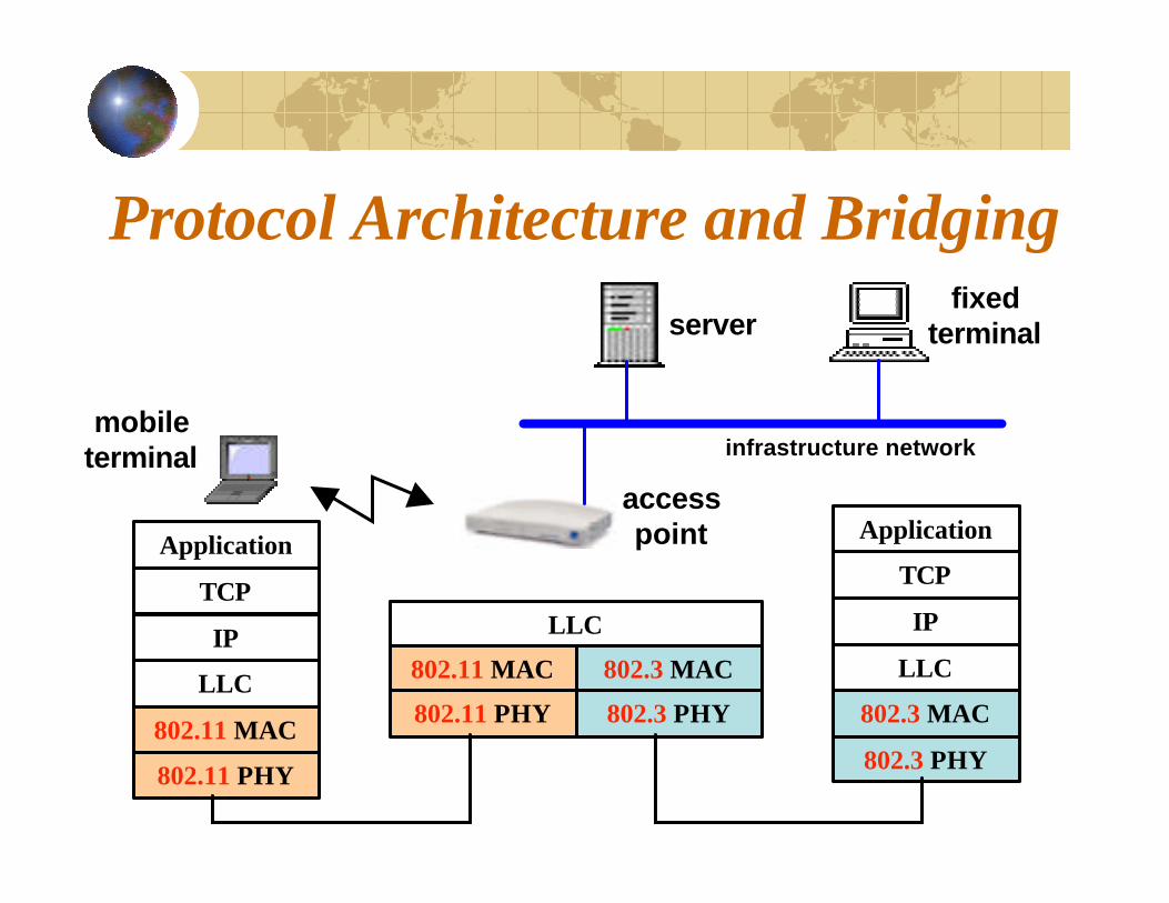
Protocol Architecture and Bridgingserver
fixed terminal
access point
mobile terminal infrastructure network
Application
TCP
IP
LLC
802.11 MAC
802.11 PHY
Application
TCP
IP
LLC
802.3 MAC
802.3 PHY
LLC
802.11 MAC 802.3 MAC
802.11 PHY 802.3 PHY

The 802.11 PHY Layer
802.11 defines THREE signaling techniques:FHSS, DSSS, IR
FHSS and DSSS operate in 2.4 ISM band.Data rates of 1 Mbps and 2 Mbps via FHSS or DSSS.

Frequency Hopping Spread Spectrum
75 1-MHz subchannels.The sender and receiver agree on a hopping pattern. Data is sent over a sequence of subchannels.Simple radio design.Limited to speed of no higher than 2 Mbps (FCC).
Direct Sequence Spread Spectrum
14 22-MHz subchannels.Adjacent channels overlap partially with THREE non-overlapping.Chipping: 11 chip sequence.Symbols:waveform representing a bit.Coding Technique: Barker Sequence.Modulation: 1 Mbps BPSK, 2 Mbps QPSK.Error checking and recovery.

802.11b Enhancements to PHY Layer
Two new speeds: 5.5 Mbps and 11 Mbps.Only DSSS.Data rates of 1 Mbps and 2 Mbps via FHSS or DSSS.Advanced coding techniques:
Complementary Code Keying (CCK)
Modulation: QPSK.Dynamic rate shifting.

The 802.11 Data Link LayerTwo sublayers: LLC and MAC.Use same 802.2 LLC and 48-bit addressing as other 802 LANs.MAC Management:
1- Synchronization.2- Association.3- Power Management.4- Security.

Access Methods
Distributed Coordination Function
Used for contention services and basis for PCF
Point Coordination Function
Used for contention free services
1- Distributed Coordination Function (DCF). BASIC2- RTS/CTS extension. OPTIONAL3- Point Coordination Function (PCF). OPTIONAL

Distributed Coordination Function (DCF)
The Near/Far Problem:To detect collision, a STA must be able to transmit and listen at the same time. In Radio systems the transmission drowns out the ability to listen.
Solution: use DCF or CDMA/CA.Explicit ACK (not used in case of broadcast or multicast frames).Randomized backoff.

CSMA/CA
Medium is idle
•Sense medium for IFS.•Wait for a random backoff time.•Sense then send if still idle.
ACKreceived
successful transmission
Frame ready
Wait a random backoff time
Medium is idle
NONOYESYES
YESYES
NONO
YESYESSEND NONO
Priorities are defined by IFSIFS:1.1. SIFSSIFS (Short IFS): ACK, CTS.2.2. PIFSPIFS (PCF IFS).3.3. DIFSDIFS (DCF IFS).

Basic Access Method

Unicast Frames (Directed Data)

Backoff Procedure

DCF with RTS/CTS ExtensionThe Hidden Node Problem.
Can not be used with broadcast and multicast.
Solution: RTS/CTS.Used for large size packets.
Carrier-sense Mechanisms
Physical Vs. virtual mechanisms (NAV).NAV maintains a prediction of future traffic based on duration information in RTS/CTS frames and MAC header frames.All STAs within the reception range of either the originating STA (RTS) or the destination (CTS) learn of the medium reservation.

RTS/CTS/data/ACK and NAV Setting

Point Coordination Function (PCF)Support of time-bounded data.Uses a Point Coordinator (PC) operating in the AP.PC polls STAs in a predetermined priority.No station is allowed to transmit unless it is polled.Not scalable, AP needs to have control of media access and must poll all stations, which can be ineffective in large networks.

PCF (Contd.)

Packet FragmentationThe process of portioning a MAC service data unit into smaller MAC level frames.Increase reliability by increasing the probability of successful transmission.Only unicast packets are fragmented.
MSDU
Frame Body
CRC
MAC HDR
Frame Body
CRC
MAC HDR
Frame Body
CRC
MAC HDR
Frame Body
CRC
MAC HDR

SynchronizationA Timing Synchronization Function (TSF) keeps the timers for all STAs in the same BSS synchronized.The AP is the timing master.APs are not synchronized.Beacons contain a copy of the AP TSF timer. Beacons are generated every BeaconPeriod time.If the medium is busy, the AP delays the actual transmission of a beacon.The BeaconPeriod is included in Beacon and Probe Response frames.
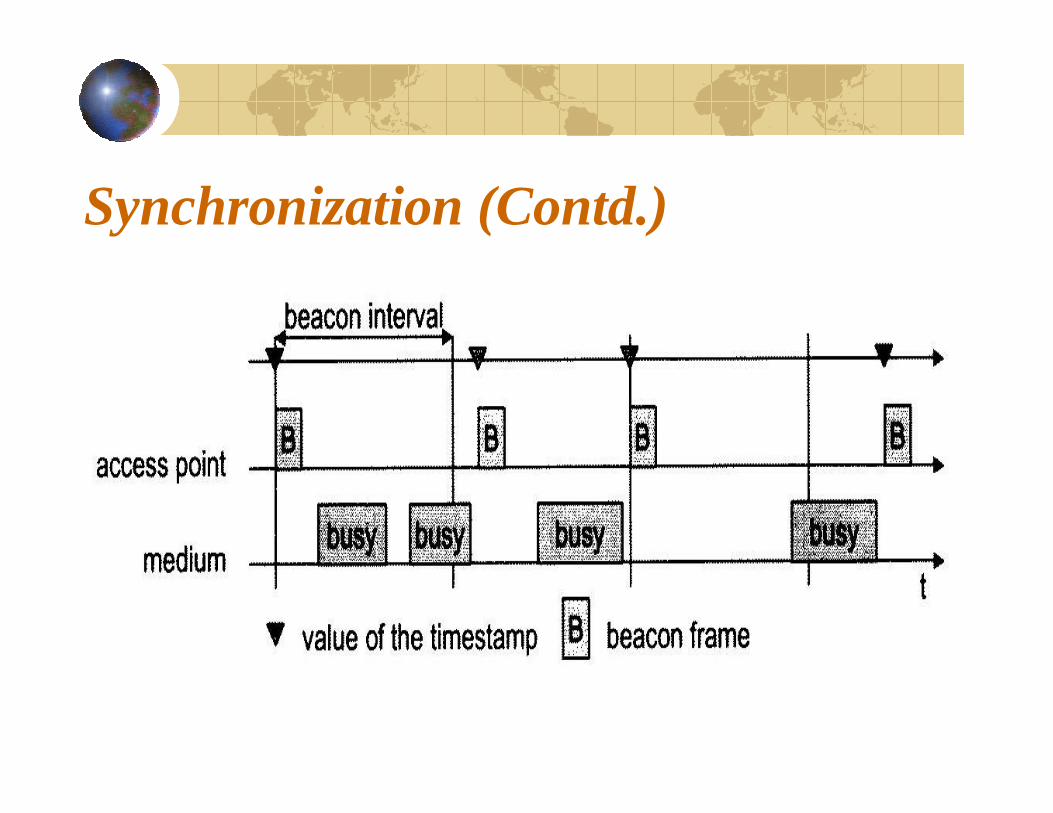
Synchronization (Contd.)

Association
When a STA enters the range of one or moreAPs, it chooses an AP based on signal strength and observed packet error rates.A STA periodically surveys all channels to assess whether a different AP provide better performance. Reassociation: roaming, change in radio characteristics in the building, load balancing.

Power ManagementA STA can be in one of two states: Awake, Doze.Two modes: Active Mode (AM), Power Save (PS).Power Save (PS) Mode:Ø AP queues any data.Ø Traffic Indication Map (TIM).Ø STA periodically listens for beacons as determined by
the STA’s ListenInterval .Ø STA transmits a short PS-Poll frame to the AP.Ø AP responds with the buffered packet immediately or
ACK the PS-Poll, respond with packet at a later time. Delivery TIM (DTIM): list of broadcast/multicast receivers.
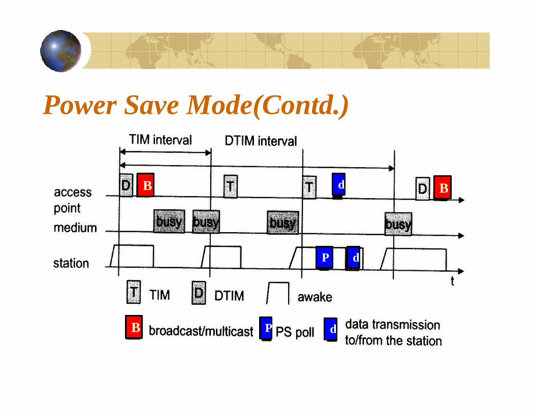
Power Save Mode(Contd.)
B
B B
P
P d
d
d
