iec 61850 el nuevo estándar en guillermo fuentes e ... · todas las 14 partes del iec 61850 fueron...
TRANSCRIPT

1
©A
BB
Pow
er T
echn
olog
ies
AB
, 20
05
2005-06-13 Gunnar Stranne
IEC 61850El Nuevo Estándar en Automatización de Substaciones
Guillermo Fuentes E

2
©A
BB
Pow
er T
echn
olog
ies
AB
, 20
05
2005-06-13 Gunnar Stranne
IEC 61850 – Introducción
� Introducción
� Objetivos del estándar
� Detalles del estándar
� Pruebas de conformidad y migración
� Conclusiones

3
©A
BB
Pow
er T
echn
olog
ies
AB
, 20
05
2005-06-13 Gunnar Stranne
IEC 61850; Promoción en Revistas Comerciales
� Publicaciones comerciales en lugar de anuncios� Noviembre de 2005; edición de
Modern Power Systems
� Febrero edición de InternationalPower Generation
� Serie IED 670; la primera en el mercado en implementar todos los aspectos del nuevo standard!!

4
©A
BB
Pow
er T
echn
olog
ies
AB
, 20
05
2005-06-13 Gunnar Stranne
¿Qué es IEC 61850?
� IEC 61850 es un estándar mundial para“Sistemas y Redes de Comunicación en Subestaciones”
� Especifica un ampliable modelo de datos y servicios� No bloquea futuros desarrollos de funciones
� NO especifíca funciones de control o protección
� Respalda la Libre Asignación de Funciones a Dispositivos� Es abierto a las diferentes filosofías de sistemas.
� Entrega un lenguaje descriptivo de configuración en la subestación(SCL)� Respalda una comprensiva y consistente definición de sistema y
ingeniería
� Usa Ethernet y TCP/IP para la comunicación� Entrega un amplio rango de características convencionales de
comunicación
� Es abierto para futuros nuevos conceptos de comunicaciones

5
©A
BB
Pow
er T
echn
olog
ies
AB
, 20
05
2005-06-13 Gunnar Stranne
IEC y el camino para el estándar IEC 61850
� La Comisión Electrotécnica Internacional (IEC) es mundial.
� Publica las normas internacionales para todas las tecnologíaseléctricas, electrónicas y relacionadas.
� Los miembros de IED son organizaciones de normalizaciónnacionales.� i.e. ni personas individuales, ni compañias.
� Expertos en los comités técnicos representan a sus países.� i.e. No ellos mismos o sus empleados.
� IEEE y EPRI trabajan bajo un esquema similar en Norte America
6
©A
BB
Pow
er T
echn
olog
ies
AB
, 20
05
2005-06-13 Gunnar Stranne
IEC e IEEE unen fuerzas en 1999 and definen…
IEC 61850:” REDES DE COMUNICACIÓN Y SISTEMAS EN
SUBESTACIONES ”� IEC 61850 es el primer estándar realmente mundial en el Área de la
Industria Eléctrica.� Respaldado también en el mundo de la ANSI/IEEE.
� Aproximadamente 60 expertos de Europa y Norteamerica handesarrollado en conjunto el IEC 61850.� Incluye el UCA 2.0 como subconjunto.
� Todas las 14 partes del IEC 61850 fueron publicadas en el 2004
� Influencia otras áreas eléctricas.� Centrales Eólicas, Hidroeléctricas, Recursos de Energía Distribuída, …
� Implementación en marcha por los más importantes fabricantes.

7
©A
BB
Pow
er T
echn
olog
ies
AB
, 20
05
2005-06-13 Gunnar Stranne
UCA e IEC – dos “estándares mundiales” unidos
… está listo ahora!
… los productosestán desarrollados!
… atrae mucho la atención de clientesy fabricantes!
Un Mundo …Una Tecnología …Un Estándar …
IEC 61850

8
©A
BB
Pow
er T
echn
olog
ies
AB
, 20
05
2005-06-13 Gunnar Stranne
IEC61850 Dominio de Aplicación: Automatización de Subestaciónes
Control Remoto (NCC)
Nivel Bahía
Nivel de Proceso
Nivel de Estación
Bus de Estaciónó Interbahía
(LAN)
Bus de Proceso (LAN)
Estación deComputación
Estacióngateway
Protección
Interface de Proceso
Interface deProceso
Interface deProceso
ControlProtecciónControl Control &Protección
Estación de Ingeniería

9
©A
BB
Pow
er T
echn
olog
ies
AB
, 20
05
2005-06-13 Gunnar Stranne
Estructura del estándar IEC 61850
Communication model (Data model and Services)Communication model (Data model and Services)Communication model (Data model and Services)
Introducción y Visión General
Glosario
Requerimientos Generales
Administración de Proyectos y Sistemas
Requerimientos de Comunicación
Estructura de Comunicación Básica (Modelo de Datos y Servicios)
Lenguaje de descripción de configuración para la comunicación
Pruebas de Conformidad
Impacto en Ingeniería
Impacto sobreofertas y adm. de
Proyectos
Parte 1
Parte 2
Parte 3
Parte 4
Parte 5
Parte 7-1…7- 4
Parte 6
Parte 10
Información yconocimiento
Impacto enla verificación
Mapeos de Bus de Proceso
Mapeos de Bus de Estación
El real ahorro!!
Modeladodel standard
Parte 9Parte 8Mapeo Mapeo Mapeo Mapeo
Stack A Stack B Stack X Stack Y

10
©A
BB
Pow
er T
echn
olog
ies
AB
, 20
05
2005-06-13 Gunnar Stranne
IEC 61850 – Objectivos del Estándar
� Introducción
� Objetivos del estándar
� Detalles del estándar
� Migración y test de conformidad
� Conclusiones

11
©A
BB
Pow
er T
echn
olog
ies
AB
, 20
05
2005-06-13 Gunnar Stranne
Objetivos para el IEC 61850 (1)
Reduce el costo de la aplicación, permite salir de la antiguapenumbra hacia la próxima Generación:
� Interoperabilidad� IEDs de diferentes fabricantes pueden intercambiar y usar información
sobre medios de comunicación comunes. � Sin embargo, la funcionalidad en los diferentes dipositivos no es necesariamente
la misma.Por lo tanto, no hay intercambiabilidad de dispositivos de diferentesfabricantes!
� La ingeniería y configuración de datos es transportable entre herramientasde fabricantes.
� Descripción abierta de IED´s.� Reduce la ingeniería y la configuración
� Las capacidades de los IEDs son descritas en forma estándar.
� Funciones, soluciones, y datos propietarios son aún permitidos y estándisponibles.

12
©A
BB
Pow
er T
echn
olog
ies
AB
, 20
05
2005-06-13 Gunnar Stranne
Objectivos para el IEC 61850 (2)
� Comunicación cerca de Equipos de Potencia.� Capacidades de comunicación, adquisición de datos, y control, deben
ser incluídas directamente en los equipos primarios.
� Libre configuración� Libre asignación de funciones en sistemas de configuraciones
centralizadas o descentralizadas.
� Reducción del cableado convencional.� LAN en lugar de multiples cables de cobre.
� A prueba de futuro� Los servicios y las inversiones serán duraderos a pesar de los rápidos
cambios tecnológicos.
� El estándar está diseñado para seguir tanto el progreso en lastecnologías de comunicación, como los requerimientos que envuelvena estos sistemas.

13
©A
BB
Pow
er T
echn
olog
ies
AB
, 20
05
2005-06-13 Gunnar Stranne
IEC 61850 – Detalles del estándar
� Introducción
� Objetivos del estándar
� Detalles del estándar
� Migración y test de conformidad
� Conclusiones

14
©A
BB
Pow
er T
echn
olog
ies
AB
, 20
05
2005-06-13 Gunnar Stranne
Comunicación de Datos en “Terminos Humanos”
IED1
Interface de Proceso
CB1
IED 1 Data“TOC Pick-up”“CB1 is Closed”“I Phase L1 is 200A”“V Phase L1 is 26.3kV”
En este ejemplo:• El elemento de protección TimeOverCurrent tuvo un pick up• El Circuit breaker está Cerrado• La corriente en la Fase L1 es 200 A• El voltaje en la Fase L1 es 26.3 kV
Proteccióny Control
Estación de Computación

15
©A
BB
Pow
er T
echn
olog
ies
AB
, 20
05
2005-06-13 Gunnar Stranne
Comunicación de Datos usando Protocolos Propietarios
IED1
Interface de Proceso
CB1
IED 1 Data“TOC Pick-up”“CB1 is Closed”“I Phase L1 is 200A”“V Phase L1 is 26.3kV”
Usando por ejemplo LON, DNP 3.0 o uno similar- El contexto de los datos se pierde.
HMI LinkageCB1 Pos = DB DW167 TOC PU = DB DW 2IL1 = DB DW 3UL1 = DB DW 4
DNP 3.0 MessagesIED1, Obj 2, Var 2, #1 = CB1 PosIED1, Obj 2, Var 2, #20 = TOC PUIED1, Obj 30, Var 4, #1 = IL1IED1, Obj 30, Var 4, #6 = UL1
DNP 3.0 DBDB DW1 = IED1, Obj 2, Var 2, #1DB DW 2 = IED1, Obj 2, Var 2, #20 DB DW 3 = IED1, Obj 30, Var 4, #1 DB DW 4 = IED1, Obj 30, Var 4, #6
Estación de Computación
Proteccióny Control

16
©A
BB
Pow
er T
echn
olog
ies
AB
, 20
05
2005-06-13 Gunnar Stranne
Comunicación de Datos usando IEC 61850
IED1
CB1
IED 1 Data“TOC Pick-up”“CB1 is Closed”“I Phase L1 is 200A”“V Phase L1 is 26.3kV”
Datos de Protección
Datos del Switchgear
Measurement DataDatos de Medidas
IEC 61850 divide los datos en grupos lógicos.En este ejemplo:• Datos de Protección (TimeOverCurrent tuvo Pick Up),• Datos del Switchgear (CB1 está cerrado) y• Datos de Medición (Los valores para V e I)
Este IED usa datos de tres grupos para supervizar el CB.
Interface de Proceso
Estación de Computación
Proteccióny Control

17
©A
BB
Pow
er T
echn
olog
ies
AB
, 20
05
2005-06-13 Gunnar Stranne
Grupos Logicos
Physical Device(network address)
Logical Device
LN1(XCBR)
LN2(MMXU)
Pos A
StV q PhA PhB
Physical Device
Logical Device1 ... N
Logical Node1 … N
Data1…N
Data attribute1…N
Bahía A
18
©A
BB
Pow
er T
echn
olog
ies
AB
, 20
05
2005-06-13 Gunnar Stranne
Logical Node
� Funciones o equipos utilizados en el Sistema de Potencia son representados en Logical Nodes, LN
� Toda la información y funciones en la subestación estánestructuradas en unidades atómicas, los LNs
� Cada LN provee a una lista bien organizada y nombrada de información.
� Funciones complejas utilizan un set de LN requeridos pararepresentar la función
� Los servicios habilitan el intercambio de información en LNs entreIEDs
� Ejemplo: el LN de un Circuit Breaker tiene el nombre genérico XCBR
� Nuevos LN pueden, si es requerido, ser creados de acuerdo a reglasdefinidas en el estándar

19
©A
BB
Pow
er T
echn
olog
ies
AB
, 20
05
2005-06-13 Gunnar StranneOCircuit breaker operating capability when fully chargedINSMaxOpCap
OPoint On Wave switching capabilityINSPOWCap
MCircuit breaker operating capabilityINSCBOpCap
Status Information
OSum of Switched Amperes, resetableBCRSumSwARs
Metered Values
OCharger motor enabledSPCChaMotEna
MBlock closingSPCBlkCls
MBlock openingSPCBlkOpn
MSwitch positionDPCPos
Controls
MOperation counterINSOpCnt
OExternal equipment name plateDPLEEName
OExternal equipment healthINSEEHealth
MLocal operation (local means without substation automation communication, hardwired direct control)
SPSLoc
MLN shall inherit all Mandatory Data from Common Logical Node Class
Common Logical Node Information
M/OTExplanationAttr. Type
DATA Class
XCBR class
XCBR - Circuit Breaker
Este LN es usado para modelar switches con capacidad de interrupción de arco. LNs adicionales como por ejemplo SIMS, etc. pueden requerirse para completar el modelamiento lógico para el breaker a ser representado. Los comandos de cierre y apertura deben ser suscritos desde CSWI o CPOW si aplica. Si no se requieren servicios de tiempo real entre CSWI o CPOW y XCBR, los comando de apertura y cierre son controlados con un mensaje GSE. (Ver IEC 61850-7-2).
CLN
Back

20
©A
BB
Pow
er T
echn
olog
ies
AB
, 20
05
2005-06-13 Gunnar Stranne
Back
OOperation timeINSOpTmh
OOperation counterINSOpCnt
OOperation counter resetableINCOpCntRs
OExternal equipment name plateDPLEEName
OExternal equipment healthINSEEHealth
OLocal operationSPSLoc
Optional Logical Node Information
MName plateLPLNamPlt
MHealthINSHealth
MBehaviorINSBeh
MModeINCMod
Mandatory Logical Node Information (Shall be inherited by ALL LN but LPHD)
M/O
TExplanationAttr. Type
DATA Class
CLN class
CLN - Common Logical Node
Las clases de LN compatibles definidos en este documento son especializaciones de estas clases de Common de LN.
T = Transient, M = Mandatory, O = Optional

21
©A
BB
Pow
er T
echn
olog
ies
AB
, 20
05
2005-06-13 Gunnar Stranne
Logical Nodes: In total 92 divided into 13 groups
4Power TransformerY
4Sensors, MonitoringS
28Protection FunctionsP
10Protection Related FunctionsR
4Automatic controlA
Further (power system) equipment
Instrument Transformer
Switchgear
Metering and Measurement
Interface and Archiving
Generic Function References
Supervisory control
System Logical Node
Logical node groups
8M
4I
3G
5C
2X
2T
5Z
3L
QtyIndicator - PDIR Directional Comparison- PDIS Distance- PSCH Protection scheme- PTOC Time overcurrent- PTOV Overvoltage
- more…
- MMXU Measuring (Measurand unit)- MMTR Metering- MSQI Sequence and imbalance- MHAI Harmonics and inter-harmonics
- more …..
- XCBR Circuit breaker- XSWI Circuit switch
- RDIR Directional element- RDRE Disturbance recorder function- RBRF Breaker failure- RFLO Fault locator- RREC Autoreclosing
- more…

22
©A
BB
Pow
er T
echn
olog
ies
AB
, 20
05
2005-06-13 Gunnar Stranne
LN: Time Overcurrent Name: PTOC
T = Transient, M = Mandatory, O = Optional
Attribute Name Attr. Type Explanation T M/OLNName Shall be inherited from Logical-Node Class (see IEC 61850-7-2)
LN shall inherit all mandatory data from Common Logical Node Class MOpCntRs INC Resetable operation counter O
Str ACD Start MOp ACT Operate T MTmASt CSD Active curve characteristic O
TmACrv CURVE Operating Curve Type OStrVal ASG Start Value OTmMult ASG Time Dial Multiplier OMinOpTmms ING Minmum Operate Time OMaxOpTmms ING Maximum Operate Time OOpDITmms ING Operate Delay Time OTypRsCrv ING Type of Reset Curve ORsDITmms ING Reset Delay Time ODirMod ING Directional Mode O
PTOC class
Common Logical Node Information
Status Information
Settings
Data

23
©A
BB
Pow
er T
echn
olog
ies
AB
, 20
05
2005-06-13 Gunnar Stranne
355 different types of data
36Controllable data
85Status information
66Measurands
14Metered values
11Physical device information
130Settings
355
13System information
QuantityData Classes - A Phase to ground amperes for phases 1, 2 and 3- Amp Amperes for non-phase related measurements
- PPV Phase to phase voltages- PhV Phase to ground voltages- Vol Voltage for measurement
- Hz Frequency- Imp Non-phase related Impedance- Z Phase Impedance
- TotW Total active power (Total P)- W Phase active power (P)- TotVAr Total reactive power (Total Q)- VAr Phase reactive power (VAr)- TotVA Total apperant power (VA)- TotPf Average power factor (Total Pf)- Pf Phase power factor (Pf)
- More….
All data in SI units

24
©A
BB
Pow
er T
echn
olog
ies
AB
, 20
05
2005-06-13 Gunnar Stranne
IEC 61850 modeling example
Bay A
PTOC (Time Over Current)
RREC (Autorecloser)
CSWI (Control – Circuit breaker)
MMXU (Measurement unit)
CSWI (Control - Disconnector)
MMTR (Metering)
BayA/CSWIBay Unit
25
©A
BB
Pow
er T
echn
olog
ies
AB
, 20
05
2005-06-13 Gunnar Stranne
IEC 61850 modeling example
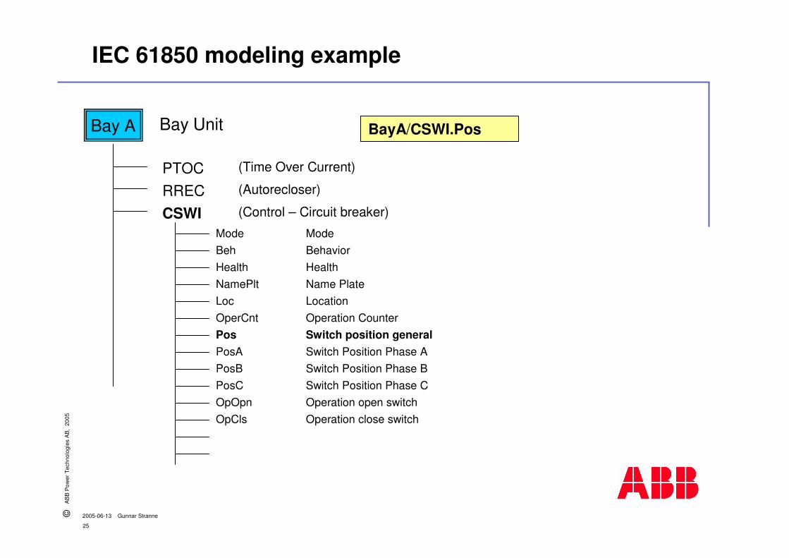
Bay A
PTOC (Time Over Current)
RREC (Autorecloser)
CSWI (Control – Circuit breaker)
BayA/CSWI.PosBay Unit
ModeBehHealthNamePltLocOperCntPosPosAPosBPosCOpOpnOpCls
ModeBehaviorHealthName PlateLocationOperation CounterSwitch position generalSwitch Position Phase ASwitch Position Phase BSwitch Position Phase COperation open switchOperation close switch
26
©A
BB
Pow
er T
echn
olog
ies
AB
, 20
05
2005-06-13 Gunnar Stranne
IEC 61850 modeling example
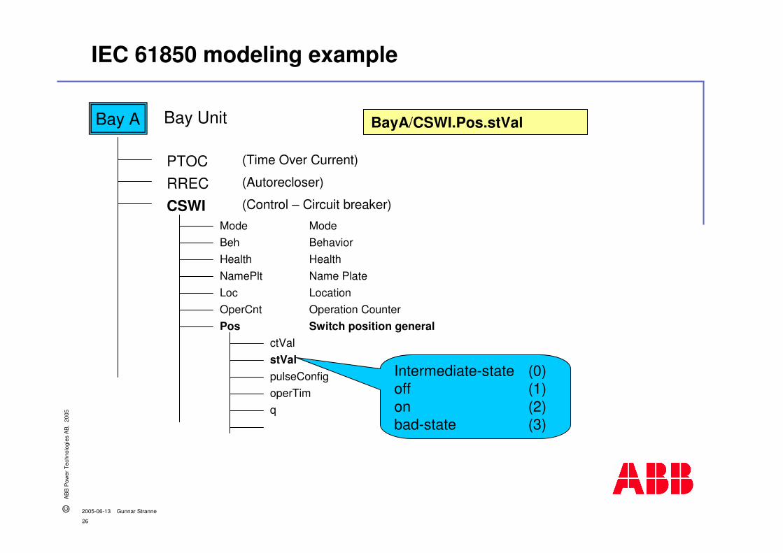
Bay A
PTOC (Time Over Current)
RREC (Autorecloser)
CSWI (Control – Circuit breaker)
BayA/CSWI.Pos.stValBay Unit
ModeBehHealthNamePltLocOperCntPos
ctValstValpulseConfigoperTimq
ModeBehaviorHealthName PlateLocationOperation CounterSwitch position general
Intermediate-state (0)off (1)on (2)bad-state (3)

27
©A
BB
Pow
er T
echn
olog
ies
AB
, 20
05
2005-06-13 Gunnar Stranne
Comunicación Horizontal (peer-to-peer)
GOOSE = Generic Object Oriented System-wide Events
Stationcomputer
Stationgateway
Protection
Process Interface Process Interface Process Interface
ControlProtectionControl Control &Protection
GOOSE

28
©A
BB
Pow
er T
echn
olog
ies
AB
, 20
05
2005-06-13 Gunnar Stranne
IEC 61850 GOOSE Prioridad de Etiquetado.
� IEC 61850 usa el estándar Ethernet
� IEC 61850 Puede tomar ventaja de todas las opciones de la Ethernetmoderna
NormalTelegrams
GOOSE
Buffer for normal telegrams
Overtake lane for IEC GOOSE
Ethernet-Switch

29
©A
BB
Pow
er T
echn
olog
ies
AB
, 20
05
2005-06-13 Gunnar Stranne
Analog Values on the Process Bus
� Corrientes and voltajes son muestreados y distribuídos a losusuarios sobre el bus de proceso LAN� Una unica Conversión A/D
� Muestreo de alta velocidad� Hasta 80 muestras por periodo para
protección (4 kHz)
� 256 muestras por período para power quality
� Muestreo directo en modernos CTs/VTs
� Muestreo en Merging Units (MU)� Merging Units convierten sistemas de
adquisiciones de datos propietarios a IEC 61850-9-2
CTs/VTs
IEC 61850-9-2Process bus
Protection
IEC 61850-8-1
MergingUnit (MU)
SampledValues

30
©A
BB
Pow
er T
echn
olog
ies
AB
, 20
05
2005-06-13 Gunnar Stranne
La LAN de la Subestación
� IEC 61850 especifica sólo la interfase de la LAN de la subestación� La LAN misma es dejada al integrador del sistema.
� La red LAN es una subparte de la subestación y necesita ingeniería, configuración, supervisión y control como cualquier otra subparte.� Un sistema de administración de red es apropiado
� La topología LAN depende del número de restricciones:� Requerimientos operacionales para la subestación
� Tamaño de la Subestación
� Confiabilidad y Disponibilidad
� etc.
� La LAN de la subestación estará bien separada en un bus de estacionesy uno o más buses de proceso.� Experiencias previas en arquitecturas de comunicaciones en subestaciones an
demostrado que este es un enfoque sensato.

31
©A
BB
Pow
er T
echn
olog
ies
AB
, 20
05
2005-06-13 Gunnar Stranne
Bus de estaciones y proceso de cableado tradicional
Router switch
NetworkControlCenter
HSI Engineering/Monitoring
IEC 61850 Stations bus
BayController
IEDA
IEDA
Switchgear CTs/VTs
BayController
IEDA
IEDA
Switchgear CTs/VTs

32
©A
BB
Pow
er T
echn
olog
ies
AB
, 20
05
2005-06-13 Gunnar Stranne
Buses separados para proceso y estaciones
BayController
IEDA
IEDA
ModernSwitchgear
ModernCTs/VTs
BayController
IEDA
IEDA
ModernSwitchgear
ModernCTs/VTs
EthernetSwitch
EthernetSwitch
Router switch
HSI Engineering/Monitoring
IEC 61850-8-1 Stations bus
IEC 61850-9-2Process bus
IEC 61850-9-2Process bus
NetworkControlCenter

33
©A
BB
Pow
er T
echn
olog
ies
AB
, 20
05
2005-06-13 Gunnar Stranne
Common station and process bus
BayController
IEDA
IEDA
ModernSwitchgear
ModernCTs/VTs
BayController
IEDA
IEDA
ModernSwitchgear
ModernCTs/VTs
EthernetSwitch
EthernetSwitch
Router switch
HSI Engineering/Monitoring
Common Stationsand Process bus
NetworkControlCenter
34
©A
BB
Pow
er T
echn
olog
ies
AB
, 20
05
2005-06-13 Gunnar Stranne
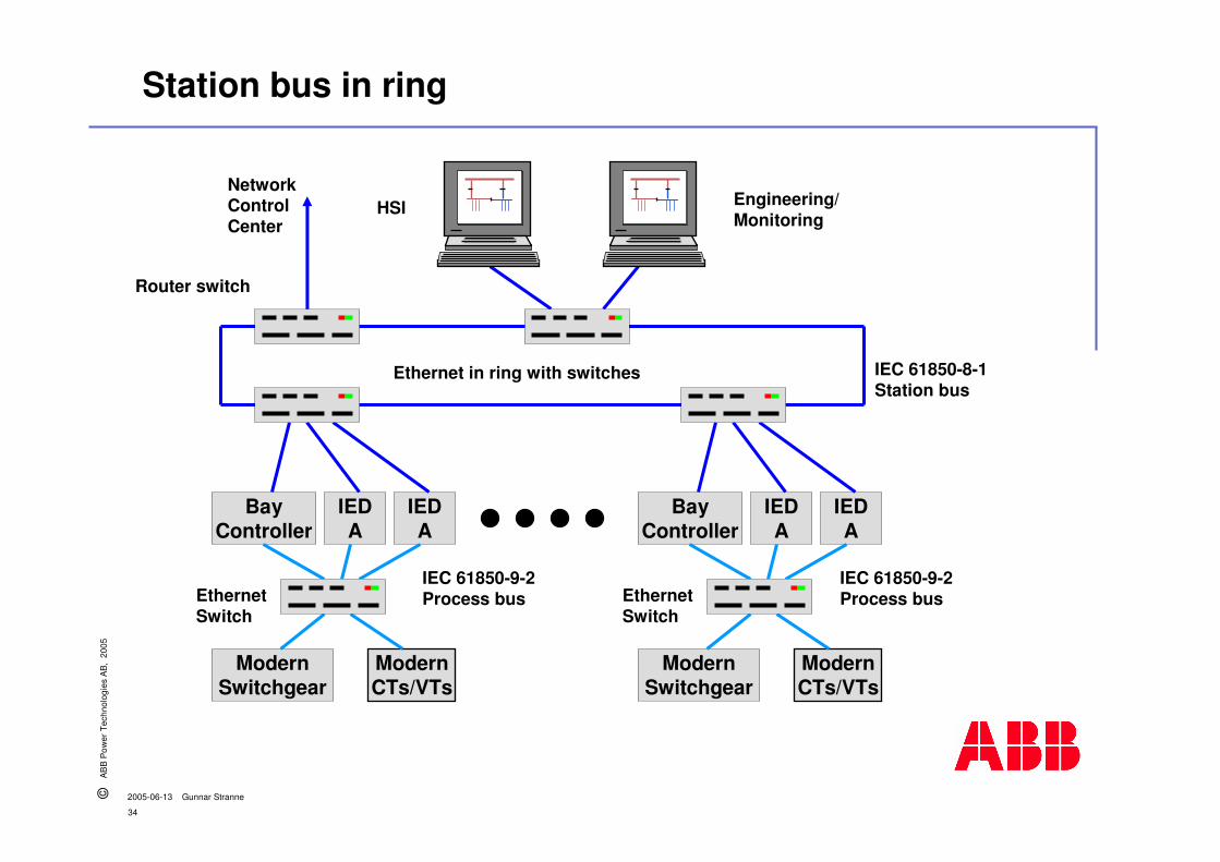
Station bus in ring
BayController
IEDA
IEDA
ModernSwitchgear
ModernCTs/VTs
BayController
IEDA
IEDA
ModernSwitchgear
ModernCTs/VTs
Ethernet in ring with switches
EthernetSwitch
EthernetSwitch
Router switch
HSI Engineering/Monitoring
IEC 61850-8-1Station bus
IEC 61850-9-2Process bus
IEC 61850-9-2Process bus
NetworkControlCenter

35
©A
BB
Pow
er T
echn
olog
ies
AB
, 20
05
2005-06-13 Gunnar Stranne
� Connects IEC 61850 nodes together� Multipurpose Ethernet switch
� Manufactured by OnTime in Norway -www.ontimenet.com
� Several network topologies supported� One T200 RealSwitch on top of the
topology � Time synchronization switch with
integral time server
� R200 RingSwitch on next levels� In principle unlimited number of
hierarchical levels
� Runs on 10/100 Mbit/s� Time accuracy better than 0,5 µs
regardless of load
Switch for an IEC 61850 network Example 1a
� 8 ports whereof max 6 can be optical� Different types of connectors available
– LC type recommended� Full flexibility regarding port
combination – TX, SM,MM� The port is learning addresses in
order to prevent flooding when it begins forwarding traffic

36
©A
BB
Pow
er T
echn
olog
ies
AB
, 20
05
2005-06-13 Gunnar Stranne
� Easy configured by means of the free OnTimeConfig tool. Any of the Ethernet ports can be used� Remote configuration through
network possible� IP address� Parameters No moving parts
or electrolytic capacitors
� User configurable fault contact� Redundant power input� High MTBF numbers
Switch for an IEC 61850 network Example 1b
� Subnets� One IEC 61850 OPC server in
MicroSCADA Pro equals to one subnet.
� Theoretically no limitation, but in practice about 4 subnets
� Maximum 30 nodes per subnet� Nodes on one subnet can be split
into several subnets when assigning the IP addresses

37
©A
BB
Pow
er T
echn
olog
ies
AB
, 20
05
2005-06-13 Gunnar Stranne
� Connects IEC 61850 nodes together� Multipurpose Ethernet switch
� Manufactured by RuggedCom Inc in Canada - www.ruggedcom.com
� Several network topologies supported� One RS1600F on top of the topology
� In principle unlimited number of hierarchical levels
� Runs on 10/100 Mbit/s
Switch for an IEC 61850 network Example 2a
� 16 optical ports� Different types of connectors
available – LC type recommended� Full flexibility regarding port
combination – SM, MM� The port is learning addresses in
order to prevent flooding when it begins forwarding traffic
RuggedSwitch™ - RS1600F

38
©A
BB
Pow
er T
echn
olog
ies
AB
, 20
05
2005-06-13 Gunnar Stranne
� LED indicators for link, activity and speed aid in field troubleshooting
� RuggedSwitch Operating System (ROS) for advanced networking features like:� Port configuration� Port mirroring� Port statistics� Port Security� Event logging and alarms
� Critical alarm relay� Redundant power input� Full duplex operation (no collisions)
Switch for an IEC 61850 network Example 2b
� High reliability� Exceeds that of commercial
Ethernet switches by having no rotating mechanical parts such as cooling fans
� by utilizing high-temperature solid-state components.
RuggedSwitch™ - RS1600F

39
©A
BB
Pow
er T
echn
olog
ies
AB
, 20
05
2005-06-13 Gunnar Stranne
Ingeniería y Configuración
� Resguardos para una ingeniería eficiente en el IED� La ingeniería de los IEDs es realizada a través de herramientas
específicas de cada fabricante.
� Las herramientas de configuración traducen las capacidades y la configuración del IED a SCL (Substation Configuration description Language)
� SCL permite el intercambio de información entre herramientasde configuración de diferentes fabricantes.
� SCL asegura la compatibilidad de diversas versiones anterioresde IEDs y la herramienta de configuración de IEDs

40
©A
BB
Pow
er T
echn
olog
ies
AB
, 20
05
2005-06-13 Gunnar Stranne
� Paso 1:� Selecionar los IEDs de acuerdo
a los requerimientosfuncionales
� Configurar los IEDs� Herramienta específica del IED
� Capacidad por defecto del IED Capacidad de descripción de archivo, ICD, como básicos.
� Crear ICD, para IEDsindividuales.
� Cargar todos los archivos ICD en el System Configuration Description database (SCD)
IED Aconfig.tool
IED Bconfig.tool
Vendor AIED
Vendor BIED
IEC 61850Ethernet
Systemconfig.tool
SubstationConfigurationDescription
IED CapabilityDescription files, ICD
System ConfigurationDescription file, SCD
Ingeniería y Configuración

41
©A
BB
Pow
er T
echn
olog
ies
AB
, 20
05
2005-06-13 Gunnar Stranne
Ingeniería y Configuración Example 2/3
IED Aconfig.tool
IED Bconfig.tool
Vendor AIED
Vendor BIED
IEC 61850Ethernet
Systemconfig.tool
SubstationConfigurationDescription
IED CapabilityDescription files, ICD
� Paso 2:� Cargar todos los archivos ICD
en el System Configuration Description database
� Definir referencias-cruzadasentre IEDs
� Seteo de parámetros en losIEDs
� Actualizar los archivos ICD individuales

42
©A
BB
Pow
er T
echn
olog
ies
AB
, 20
05
2005-06-13 Gunnar Stranne
Ingeniería y Configuración Example 3/3
� Paso 3:� Cargar los ICD desde el System
Configuration Description database
� Crear los archivos de parametrosrun-time individualmente paracada IED´s
� En formato específico del fabricante
� En formato SCL comoConfigured IED Description file (CID)
� Cargar los archivos run-time individualemente en IEDs
� MMS services
� FTP
� Método propietario
IED Aconfig.tool
IED Bconfig.tool
Vendor AIED
Vendor BIED
IEC 61850Ethernet
SubstationConfigurationDescription
IED CapabilityDescription files, ICD
System ConfigurationDescription files, SCD

43
©A
BB
Pow
er T
echn
olog
ies
AB
, 20
05
2005-06-13 Gunnar Stranne
IEC 61850 – Migración y Test de Conformidad
� Introducción
� Objetivos del estándar
� Detalles del estándar
� Migración y test de conformidad
� Conclusiones

44
©A
BB
Pow
er T
echn
olog
ies
AB
, 20
05
2005-06-13 Gunnar Stranne
Migración a IEC 61850
� La migración es técnicamente posible sí: � Se reemplazan los dispositivos a nivel de estación.
� Se reemplaza total o parcialmente los dispositivos a nivel de bahía.
� Se reemplazan total o parcialmente los dispositivos de proceso.
� Se extienden con una o más bahías
� La migración podría no ser rentable.� Dos clases de mantenimiento en instalaciones mixtas.
� No hay beneficios funcionales
� Se debe considerar migrar la subestación completa!

45
©A
BB
Pow
er T
echn
olog
ies
AB
, 20
05
2005-06-13 Gunnar Stranne
Migration a Nivel de Estación
� Estaciones de computación y gateways serán compatibles por mucho tiempo con losactuales protocolos e interfaces
� La separación entre lasfunciones de comunicación y operador permitirá un mix de protocolos en el bus de estación. e.g. IEC 61850-8-1 y LON� Problemas si el bus de
estación es usado paraintercambios ráidos entrepares, e.g. Enclavamientos, la transferencia entre dos buses puede tomar tiempo.
NewStationcomputer
Process Interface
BayController
IEDA
IEDA
Switchgear CTs/VTs
IEC 61850-8-1
IEC 61850-9-2
Old station bus

46
©A
BB
Pow
er T
echn
olog
ies
AB
, 20
05
2005-06-13 Gunnar Stranne
Migración en niveles de bahía y de proceso
� Reemplazo solamente de un IED� Reemplazar un IED con conector compatible, si es posible compatible
con IEC 61850
� Retrofit of bay� Seleccionar un set de IEDs compatibles con IEC 61850, los fabricantes
deben tener un IED compatible con IEC 61850 e interfaces actualmente compatibles
� Extensiones con una nueva bahía� En cuanto a retrofit, pero considerar también un bus de proceso full.
� Retrofit de equipo primario o transductor/actuador� Lo mismo que para retrofit de nuevas bahías

47
©A
BB
Pow
er T
echn
olog
ies
AB
, 20
05
2005-06-13 Gunnar Stranne
Test de Conformidad
� Las pruebas de conformidad incluyen verificación de la información y herramientas suministradas por el fabricante, como por ejemplo:� La descripción formal del IED dentro del archivo ICD, de Descripción de
Configuración del IED.� El SCD, System Configuration Description, archivo que describe el
sistema usado para la configuración del IED.
� Las pruebas de conformidad pueden ser llevadas a cabo por el fabricante mismo o por una organización de pruebas independiente, como KEMA
� Interoperabilidad entre productos de diferentesfabricantes garantizado por:� Programa de aseguramiento de calidad durante el desarrollo,
introducción al mercado, y ejecución del proyecto.� Test de conformidad (test tipos) para las capacidades de comunicación.

48
©A
BB
Pow
er T
echn
olog
ies
AB
, 20
05
2005-06-13 Gunnar Stranne
IEC 61850 – Conclusiones
� Introducción
� Objectivos del Estándar
� Detalles del Estándar
� Migracion y test de conformidad
� Conclusiones
49
©A
BB
Pow
er T
echn
olog
ies
AB
, 20
05
2005-06-13 Gunnar Stranne
¿Qué NO es parte de IEC 61850?
� Funciones del producto no standarizadas y no incluídas
� Funciones del operador y interfasesde operador NO son estandarizadasy no están incluídas
� Productos de diferentes fabricantesson interoperablesperono necesariamente intercambiables
� ..así que todavía importa a quesuministrador seleccionan losclientes!
Queda porcompetir …

50
©A
BB
Pow
er T
echn
olog
ies
AB
, 20
05
2005-06-13 Gunnar Stranne
IEC 61850 – Beneficios y Conclusiones
� EL estándar para automatización de subestaciones!
� Alto grado de flexibilidad a través de la interoperavilidad entre IEDs de distintos fabricantes.
� Toma una completa ventaja para futuras innovaciones con tecnologías de Automatización de Subestaciones y Comunicaciones
� Promete reducción de costos desde el diseño hasta la operación y mantenimiento!
� Arquitectura de Subestación adaptada a sus requerimientos!
� Da la oportunidad de dar un ‘Mejor valor al dinero’
� Acogida por fabricantes y usuarios equitativamente!
51
©A
BB
Pow
er T
echn
olog
ies
AB
, 20
05
2005-06-13 Gunnar Stranne
IEC 61850 - Referencias / Links
� IEC standards portal
� IEC 61850 all parts
� UCA International Users grouphttp://www.ucausersgroup.org

52
©A
BB
Pow
er T
echn
olog
ies
AB
, 20
05
2005-06-13 Gunnar Stranne
IEC 61850 in Substation Laufenburg, CH
100 Mbit/sEthernet ring bus
...
IEC 61850
...
380kV Feeder Wiesental Nord .......................................................
COM581
REC316
RIO580
REL316
Third party
Feeder xy
IEC60870-5-101
MEINBERGNTP Timeserver
Migration of7 feeders in total
Existing Third Party
Existing
Cubicles
Hard-wired
Existing Third Party
ABB scope of supply
Station is renewed by ABB(article is available)
