iea hydrogen task 18: evaluation of integrated
TRANSCRIPT

IEA Hydrogen Task 18: Evaluation of Integrated Demonstration Systems
Susan SchoenungLongitude 122 West, Inc.
May 25, 2005
Project ID #SAP1This presentation does not contain any proprietary or confidential information
122 West2005 DOE Hydrogen Program Review, Crystal City, Virginia, 23-26 May, 2005

2
Overview of IEA Integrated Systems Project (Task 18)
• Project start date: January 1, 2004
• Project end date: December 31, 2006
• Percent complete: ~44%
• To safety, codes and standards– Conflicts between domestic and international C&S
• To systems analysis– Lack of consistent data, assumptions and guidelines; lack
of consensus on modeling tools
• To tech validation– Inadequate integrated infrastructure system experience;
lack of validated data
• Total project funding– DOE share: $450K– Contractor co-share: contributed labor
(~$50K)– International partners: 18 FTE
• Funding received in FY04: $98K• Funding for FY05: $107K
Timeline
Budget
Barriers Addressed from MYPP
• International Energy Agency, Hydrogen Implementing Agreement
Task 18 members:• Eleven countries• European commission
• Sandia National Laboratory (Lutz)• Los Alamos National Laboratory (Padró)
Partners / Collaborators

3
Participants of IEA Hydrogen Task 18CanadaNatural Resources Canada
JapanAIST Laboratory
ItalyENEA
IcelandIcelandic New Energy
NorwayIFE
SpainINTASwedenSydkraft
United KingdomEA Technology
United StatesDepartment of Energy
Potential members: Netherlands, Korea, Australia, Singapore
FranceCEA
DenmarkGas Technology Center
European CommissionJoint Research Center

4
Objectives of IEA Hydrogen Task 18
1)To use modeling and analysis tools to evaluate hydrogen demonstration projects. Focus is on lessons learned and providing design guidance for future projects.
2)To develop information datasets and compiled summaries of integrated hydrogen system demonstrations and development plans. Focus is on determining patterns and the evolution of trends from lessons learned.
3) To participate in Hydrogen Resources Study: “Where will the hydrogen come from?”

5
Approach => Collaboration• Members of IEA Hydrogen Implementing Agreement Task 18 work
collaboratively within two subtasks:– Subtask A: Information Base Development– Subtask B: Demonstration Project Evaluation
• U.S. DOE Sponsors the Operating Agent; Subtask Leaders are sponsored by Canada and Norway, respectively
• Subtask A: Members Responsibilities:– Deliver to searchable web portal national studies and requested data
• Subtask B: Members Responsibilities:– Work as a group to establish a list of desired data for each project– Bring to the group data from that country's project– Clarify with the data provider any limitations on data release or use– Make use of appropriate modeling & analysis tool for selected projects – Provide assessments & evaluations of the project based on the analysis results
• Members/experts meet twice per year to review progress; ongoing collaboration is carried out electronically
• Members deliver progress reports annually

6
Technical Accomplishments/ Progress/Results
• Subtask B: Analysis of 8 demo projects completed or underway: – Spain - UK– Sweden - Japan (2)– Iceland - US– Canada
• All assessments include documentation of safety, codes and standards
• Subtask A: Database contains 83 documents, analysis in progress• Case studies: 3 completed within the last year
– California Fuel Cell Partnership (US)– Compressed Hydrogen Infrastructure Project (Canada)– Fuel Cell Innovative Research System for Telecommunication (Spain)
• Hydrogen resources study in progress: – “Where will the hydrogen come from?” (in Collaboration with
Padró/LANL)

7
UK NORWAY
Project LocationsProject Locations
ICELANDSWEDEN
JAPAN
CANADA
US
SPAIN ITALY
DENMARK
FRANCE
8
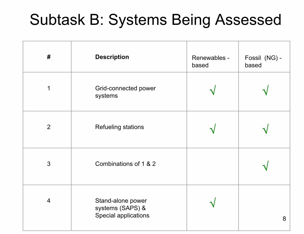
Subtask B: Systems Being Assessed
# Description
1
2
3
4
Grid-connected power systems √ √
Refueling stations √ √
Combinations of 1 & 2 √
Stand-alone power systems (SAPS) & Special applications
√
Renewables -based
Fossil (NG) -based

9
PV/ H2 Telecom System, Madrid, Spain
1500 WPV-array
360 AhBattery1000 W
PEM Electrolyzer400 WPEM Fuel Cell
70 Nm3
MH
Load
Hydrogen storage system
Telecom equipment
48 V DC busbar
= =
= =
170 W3.6 kWh/day
Charge controller
DC/DC converter
Evaluation status: Model complete, sensitivity studies in progress

10
Integrated H2 System, Atsugi, Japan
1.6m1.0m
1.0m
Water Electrolyzer (5Nm3/h)(Commercial Unit)
Grid Electricity
1.7m
2.6m
Electrolyzer
1.7m
0.3m× 0.3m× 0.53m
Temperature Controlled BathMetal Hydride Tank
(750kg)
Fuel Cell (5kW)
300A× 0.5m
Load Circuit
AtmosphereFlow Meter
Condenser
MH Temp. Control
Water Electrolyzer (3Nm3/h)(Improved Unit)
(Heat Recovery) (Gas Cooling)Temp. Controlled Bath(Hot & Cold Heat Recovery) Flow Control
Cell Stack Temp. Control
Humidity Control
Flow Meters
Pressure Control
Dehumidifier
Flow MeterHumidifier
Evaluation status: Data collection in progress, analysis to come

11
Hydrogen and RenewablesIntegration (HARI) Project - UK
Evaluation status: Data acquisition in place, modeling tools in development

12
H2 Refueling Station, Malmö, Sweden
Evaluation status: Data analysis complete, sensitivity studies in progress
Slow Fill

13
H2 Energy Station, Las Vegas
Evaluation status: Safety analysis complete, additional data unavailable

14
H2 Fueling Station, Reykjavik
Evaluation status: Data collection complete, performance analysis scheduled
15
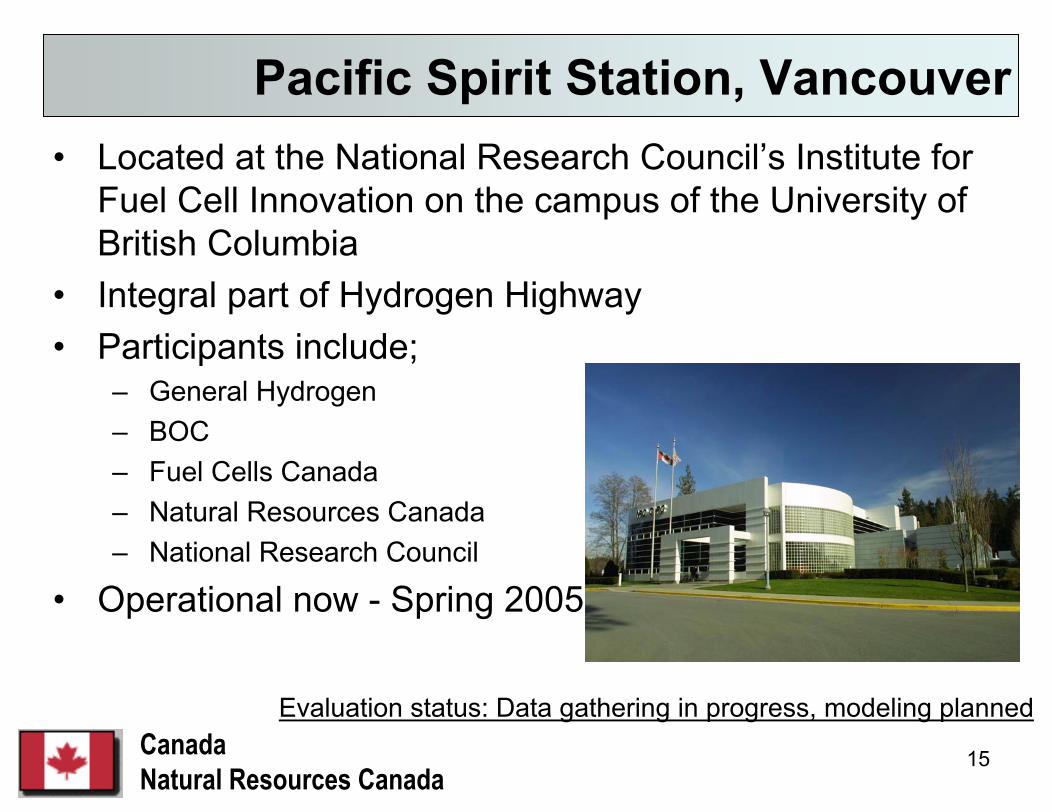
• Located at the National Research Council’s Institute for Fuel Cell Innovation on the campus of the University of British Columbia
• Integral part of Hydrogen Highway• Participants include;
– General Hydrogen– BOC– Fuel Cells Canada – Natural Resources Canada– National Research Council
• Operational now - Spring 2005
Pacific Spirit Station, Vancouver
CanadaNatural Resources Canada
Evaluation status: Data gathering in progress, modeling planned

16
Renewable H2 Project, Utsira, Norway
Evaluation status: Planning for Phase 2

17
Italian BEAM Project - Power and Fuel from Urban Waste
Evaluation status: Planning for Phase 2

18
Two Basic Types of System Studies / Documentation
I. H2-refueling stations1. Future scenario/sensitivity study (Malmö)2. Overall system performance study (Reykjavik)3. Overall system performance study (Vancouver)4. Comparative study of refueling station experience
(Reykjavik, Vancouver, Malmö, & others: Japan, Singapore, Las Vegas?)
II. Integrated RE/ H2-energy systems1. Detailed technical system performance study (Japan)2. General technical system performance study (Spain)3. Techno-economic system design study (UK)4. Future (Italy, Norway, New Zealand?)

19
Models for Evaluation and Design Guidance
1. Time series simulations (η is calculated)– Dynamic performance – Detailed system design & controls √
2. Steady-state approximations (η is provided)– General system design– H2-energy pathway studies
3. Economic calculations– Cost of energy √– Based on capital, O&M, and estimated lifetimes
4. Environmental damage calculations (LCA)– Material & energy usage, emissions over system
lifetime5. Combinations of the above

20
Time Series ModelingBasic Data Requirements
• Inputs (forcing functions)– RE-source (e.g. solar radiation, wind speeds)– Electrical and/or thermal energy load profiles – Other forcing functions (e.g., H2-refueling station duty cycle)– Minimum resolution on data: hourly values
• Parameters – System Specifications– Rated powers, H2-flow rates, etc.– Max. or min. temperature, pressure, etc.– Cells in series per stack, stacks in series per unit, etc.– Minimum requirement: clearly defined system
• Parameters – Component characteristics– IU-curves– PCT-curves– η-curves– Minimum requirement: Tables with numerical values
• Other vital items– Information on control strategy (including start-up regimes, idling and/or on/off-
switching of components)– Minimum requirement: Schematic of overall control strategy

21
Subtask A: Information Base Development
• National plans• Demonstration progress• Hydrogen resources• Vendors• Utilization rates• Geographic information• Refueling projections• Costs• Infrastructure• Codes and Standards• Economic analysis
Annex 18 website: Searchable portal

22
Information Base Development -Progress
• Initiated the definition of a structure for the proposed Information Base: Technology, Market and Supply chain.
• Participants took a step back from the usual technological viewpoint and considered the possibility to document “hydrogen” in consideration of the hydrogen energy Macroenvironment and determined that Subtask “A” would perform a Monitoring (What is going on ?) function.
• 83 documents from 11 countries being analysed for priorities and trends; additional documentation anticipated.
SocialSocial
EconomicEconomic
PoliticalPolitical
TechnologicalTechnologicalEcologicalEcological
InstitutionalInstitutional

23
Task 18 Milestone Schedule
2004 2005 2006
Expert MeetingsKO F04 S05 F05 S06 F06
Subtask AData plan and format XInitial summaries XUpdated summaries X XDraft and final report X XHydrogen Resourcestudy - input
X X
Subtask BCase Studies X X X X X X X XProject selection XTools operational XData gathering ongoing ongoingFirst demo evaluation XSecond demo evaluation XThird demo evaluation XFinal summary report X

24
Future Work: Plans for 2005-2006Technical progress plans
•Draft input to Hydrogen Resources study due by end of May; final by September•Telecom system analysis, Malmö sensitivity studies and Iceland refueling station performance analysis all due by end of 2005•Data gathering on Japan project, Vancouver refueling station and HARI project ongoing through 2005 for analysis in 2006•Comparative assessment of refueling station experience - draft due spring of 2006•ECTOS Case Study to be completed in 2005, HARI in 2006
Management plans•Task Experts meet twice per year; fall 2005 meeting is scheduled for Iceland in September; spring 2006 meeting is planned for Vancouver in March•Operating agent meets twice a year with Executive Committee; fall 2005 meeting planned for Singapore in September•Semi-annual reports due in September and April, annual in December

25
Supplemental Slides

26
Publications and Presentations• 2004 NHA Conference Poster
– Schoenung, Susan. “Hydrogen Integrated Systems Modeling and Analysis for the International Energy Agency”
• 2004 Windsor Workshop Presentation– Dubé, Jean, and Susan Schoenung. “International Energy Agency
Hydrogen Implementing Agreement; Task 18 - Integrated Systems Evaluation”• 2004 Australian Hydrogen and Fuel Cells Conference paper and presentation
– Ulleberg Ø. and R. Glöckner. “Development of Renewable Energy/Hydrogen Systems: From Concepts to Actual Demonstrations.” Hydrogen and Fuel Cells Futures Conference,Perth, 12-15 September 2004.
• H2004 Workshop Presentation– Ulleberg, Øystein. “IEA H2 Annex 18: Integrated System Evaluations.” Murdoch University, 16-17
September, 2004.• Las Vegas Energy Station safety study
– Skolnick, Ed. “Site Visit Report:The Las Vegas Hydrogen Energy Station”• Case studies (Available on IEA Hydrogen Implementing Agreement website:
http://www.ieahia.org/case_studies.html)– Gromis, Adam, and Thomas Schucan. “California Fuel Cell Partnership.”– Wong, Joe, and Thomas Schucan. “Compressed Hydrogen Infrastructure Program.”– Argumosa, Maria de Pilar, and Thomas Schucan. “Fuel Cell Innovative Research System for
Telecommunications.”• Public Website: www.port-h2.com/IEA-Annex-18/
27
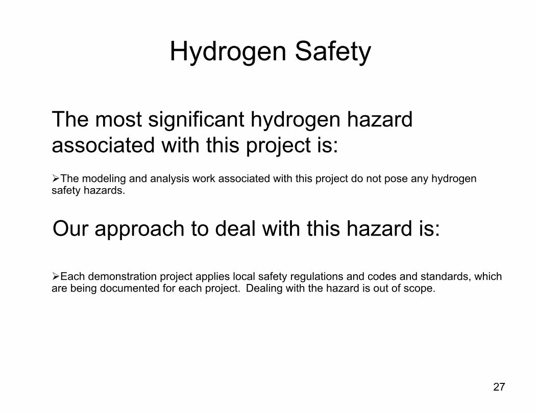
The most significant hydrogen hazard associated with this project is:
The modeling and analysis work associated with this project do not pose any hydrogen safety hazards.
Our approach to deal with this hazard is:
Each demonstration project applies local safety regulations and codes and standards, which are being documented for each project. Dealing with the hazard is out of scope.
Hydrogen Safety