ida gamma-ray laser annual summary report (1987 ... · copy 15 of 50copies l() o ida paper p-2083...
TRANSCRIPT

copy 15 of 50copies
L()o IDA PAPER P-2083
IDA GAMMA-RAY LASERANNUAL SUMMARY REPORT (1987)
INVESTIGATION OF THE FEASIBILITY OFDEVELOPING A LASER USING NUCLEAR TRANSITIONS
Rohdan BalkoLeslie Cohen
David A. SparrowJeffrey F. Nicoll
December 1988
Prepared forStrategic Defense Initiative Organization
Innovative Science and Technology Office
Dwight Duston, Acting Director
OTICMAR 1 31989'
DSTrUlO NSR
Approvf6, h'1 pubbi r.*e'Is;Dj9A iU1-L Un1ritd
IDA Log No. HO 87-33002

DEFINMO0
IDIAFPWWW~f hasis rW o d f w0
WONOLq mugs pma I a due sed ONpu Ia xamgS N
PallMi MeUWueeBON-1kam nmliii WM Sy Or valuim WM~uuIuL IDA.M
No ,uat dpa uslwN Niadmud r Plume d a tmk. ad hu m, plus me"MIL. Pipes US fmsed 6a- NOS Se, mea aleelue ulml In n 1equ spebtMklasd 1eu 0 b pauud laule
eilihu 19 Naub melkia Paim. 11 u l e auh Mt dey sof o irblepeeP MI e l awd ONlum aleealle Nueal mulyI Iewel
do urns dt am huiodee Riled ft umibm RtubI is s" ie uhno"
The rash t B A swm awe goeulu by bIlg mlleal MWumma Ig "ugad ut leelpel by In spum. whoe appI.I
Thw e s rpeow In we OWN mua - eshuudmi uia Ma c owC hi rgo 1k bm duuka at blu. Thu pilleeu dt We BA deumu a som boo Isial udu
1ukya epIea Id Odoumow us luf In sMao be mehedi am lmp ft1
ublelels. l NOW m0019"a MeIIWle Uld Sal Uw uielu Oim Nuw ftI:owO IAppriW fo pof I i 0 w0

* UNCLASSIFIEDSECURITY CLASSIFICATION OF TffIS PAGE
REPORT DOCUMENTATION PAGEis. REPORT SECURITY CLASSIFICATION 1b. RESTRICTIVE MARKINGS
UNCLASSIFIED2a. SECURITY CLASSIFICATION AUTHORITY 3. aasrRImUTION/AVAILABILITY OF REPORT
NA2b. DECLASSIFICATIONIDOWNGRADING SCHEDULE Approved for public release; distribution unlimited.
NA4. PERFORMING ORGANIZATION REPORT NUMBER(S) S. MONITORING ORGANIZATION REPORT NUMBER(S)
lieIDA Paper P-208Ga. NAME OF PERFORMING ORGANIZATION 6b. OFFICE SYMBOL 7.. NAME OF MONITORING ORGANIZATION
Institute for Defense Analyses aplcbe DOD-IDA Management Office, OUSDRE6c. ADDRESS (City, Stain. and Zip Code) 711. ADDRESS (CITY, STATE, AND ZIP CODE)
1801 N. Beauregard Street 1801 N. Beauregard StreetAlexandria, VA 22311 Alexandria, VA 22311
so. NAME OF FUNDINGISPONSORING Sb. OFFICE SYMBOL 9. PROCUREMENT INSTRUMENT IDENTIFICATION NUMBER* ORGANIZATION Strategic Defense MDA 90384iCa0031
&c. ADDRESS (City, Sal, oid Zip Code) 10. SOURCE OF FUNDING NUMBERS
The Pentagon PROGRAM PROJECT TASK NO. WORK UNITWashington, DC 20301-7100 ELEMENT NO. IT-R2-31 6 IACCESSION NO.
* 11. TITLE (ichude Security Claaellicatimn) IDA Gamma-Ray Laser Annual Summary Report (1987):Investigation of the Feasibility of Developing a Laser Using Nuclear Transitions
12. PERSONAL AUTHOR(S).
Bohdan Balko, Leslie Cohen, David A. Sparrow, Jeffrey F. Nicoll13. TYPE OF REPORT 3b8. TIME COVERED 14. DATE OF REPORT (Year, MoMb. Day) I&iS PAGE COUNT
Final FRO 1o 10/86 TO 9/87 December 1988 j 87* 16. SUPPLEMENTARY NOTATION
17. COSATI CODES 1I& SUBJECT TERMS (Conthweo on revers N necessary aid Idenily by block number)
FIELD GROUP SUB-GROUP Nuclear Laser, Gamma-ray laser, Graser, SUperradlance, Massbauer effectBorrmann effect, Nuclear Isomers, Nudlear magnetic resonance, line-narrowing,Nuclear data, Nuclear structure, Inhomogenous broadening, energy deposition,temperature rise during pumping
Ill. A13STRACT (Couitim on rer N nuesocwy mid dMlny by block number)
This report summarizes the IDA research effort in FY 1987 in investigating thefeasibility of developing a y -ray laser.
20. DISTRIBUTION/AVAILASILITY OF ABSTRACT 2.ASRC EUIYCASFCTO03 UNCLASSIFIEDIUNLIMITED "ISME AS RRT. 03 oTIC USERS UNCLASSIFIED
22.. NAME OF RESPONSIBLE INDIVIDUAL 22k. TELEPHONE (Inchie Area Code) 22c. OFFICE SYMO
Bohdan Balko (703) 578-2991D0 FORM 1472& "4 MAR 83 APR edition may be used until exused.
AN othier odkIton. are obeolete SECURITY CLASSIFICATION OF THIS PAGE
UNCLASSIFIED

IDA PAPER P-2083
IDA GAMMA-RAY LASERANNUAL SUMMARY REPORT (1987)
INVESTIGATION OF THE FEASIBILITY OFDEVELOPING A LASER USING NUCLEAR TRANSITIONS
Bohdan BalkoLeslie Cohen
David A. SparrowJeffrey F. Nicoll
December 1988
IDAINSTITUTE FOR DEFENSE ANALYSES
Contract MDA 903 84 C 0031Task T-R2-316
PREFACE
In January 1985, Dr. James A. Ionson, then Director of the Science and
Technology Directorate of the Strategic Defense Initiative Organization (SDIO) asked
members of the IDA research staff to investigate the feasibility of developing a gamma-ray
0 laser. The staff determined what work had been done, who was currently working in the
field, and what work should be encouraged or supported. Then a workshop was convened
for research workers directly involved both in gamma-ray laser work and in ancillary fields
such as nuclear structure, radiation propagation in crystals, M6ssbauer effect, and optical
lasers. Next, an in-house study was undertaken to clarify critical issues concerning the
various pumping schemes proposed at the workshop as well as systems questions about
the gamma-ray laser as a working device.
The proceedings of the workshop were published in the form of a report to the
Innovative Science and Technology Office (IST) of the SDIO. The work completed in
1985 is presented in IDA Paper P-202 1, "IDA Gamma-Ray Laser Annual Summary Report
(1985): Investigation of the Feasibility of Developing a Laser Using Nuclear Transitions"
(Ref. 1).
In 1986, the in-house work focused on extending the data base, the nature of
superradiance in the gamma-ray laser context, and a detailed investigation of the
upconversion pumping scheme. A discussion of nuclear systematics, investigations of
electron-nuclear-driven pumping, and lifetime measurements rounded out that study. The
results of the FY 1986 effort are presented in IDA paper, P-2004 (Ref. 2).
The development of a gamma-ray laser is viewed as a high-risk/high-payoff
undertaking. IDA's involvement focuses on minimizing the risk and on striving to redirect
10 the effort when proposed schemes are shown not to be feasible.
In 1987, the IDA research staff looked at the state of the art and assessed the
situation in gamma-ray laser work (described in Chapter I). Focus was on two areas of
research interest critical to three concepts for developing a gamma-ray laser. In Chapter II0 the heating effects associated with upconversion techniques are discussed. Although the
iii

work concentrated on the direct upconversion of nuclei with electromagnetic radiation, the
results of the studies also apply to upconversion through the mechanism of electron-nuclear
coupling. In the second study (Chapter III), the sources of inhomogeneous broadeningwhich destroy the M6ssbauer effect are investigated and the techniques available for
restoring the resonance (destroying the effect of inhomogeneous broadening) by external orinternal fields are considered. An old concept for doing this is reviewed and two new
approaches are introduced.
This report does not have an overall introduction. Each chapter is an independent
study containing its own introduction.
O
iv

S
ABSTRACT
This report summarizes the IDA research effort in FY 1987 in investigating the
feasibility of developing a y-ray laser.
S
Accession For
NTIS- GRA&I* DTIC TAP ,l
Unawinici.oed U
Dj stl inu ca/ 10
'!y . .. . L o
;t I In 1_1 0 _
V!&
v

CONTENTS
Preface ................................................................................................ i
A bstract ................................................................................................ v
Sum m ary ........................................................................................... S-1
I. ASPECTS OF THE CURRENT STATUS OF THE GRASER--Leslie Cohen ... 1
A. Introduction ........................................................................... 1
B. Multipole Radiation ..................................................................... 5
* C. Linewidths ........................................................................... 10
D. Cross Sections ...................................................................... 13
E. Stimulation Systems ............................................................... 16
F. The Gas Graser ..................................................................... 191. The Velocity Zero .............................................................. 192. The Velocity C ................................................................. 20
G. The M6ssbauer Solid ............................................................... 21
H. Present Approaches to the Graser ................................................ 23
I. General Graser Problems and Needs ............................................ 24
J. Scheme-Specific Problems ........................................................... 251. Long Lifetime ..................................................................... 25.2. Upconversion .................................................................. 253. Electron-Nuclear Excitation ................................................... 25
II. HEATING DURING UPCONVERSION IN A GAMMA-RAY LASER--David A. Sparrow ...................................................................... 27
A. Introduction ............................................................................ 27
B. Sample Calculation--5 7Fe ............................................................ 28
C. Upconversion with Finite Width Beams ........................................... 32
* D. Loopholes ........................................................................... 35
E. Conclusions ............................................................................ 38
III. AN INVESTIGATION OF THE DESTRUCTION BY INHOMOGENEOUSBROADENING OF RESONANCE IN ISOMERIC CRYSTALS AND ITSRESTORATION BY SPECIAL EFFECTS--Bohdan Balko and
* Jeffrey F. Nicoll ....................................................................... 39
vii

A. Introduction ............................... ........39
B. Resonant Lineshapes and Mossbauer Experiments.........................40
C . Inhomogeneous Broadening ............................................. 43
D. The Mossbauer Resonance in the Presence of InhomogeneousBroadening..............................................................47
E. Decreasing the Effect of Inhomogeneous Broadening in MossbauerExperiments............................................................. 51
F. Conclusions............................................................. 56
References ........................................................................ 57
Appendix A-- Evaluation of the Thin Absorber Intensity............................ A-1
Appendix B-- A Discussion of the Effects on Lineshape of theMossbauer Thickness Parameter .................................... B-i
Appendix C-- Some Definite Integrals Useful in Lineshape Evaluation.............. C-1
viii
FIGURES
1. Nagle's historical growth curve for the generation of coherentelectrical and electromagnetic waves ..................................................... 2
2. The level spectrum of 11 C .................................................................... 3
3. The level spectrum of 23 5U .............................................................. 4
4. The tw o-level system .......................................................................... 5
5. The nuclear shell model .................................................................... 80 6. The half-lives of electromagnetic transitions ............................................. 9
7. Internal conversion coefficients for various multipole transitions innuclei of atomic numbers 30, 60, and 90 .............................................. 12
0 8. Emission and absorption spectra for stationary nuclei. The dotted curvesrepresent the Doppler-broadened spectra for nuclei at the temperature T .............. 14
9. Spontaneous and stimulated emission from an electromagnetic
system contained in a black box ......................................................... 18
* 10. Doppler-broadened emission and absorption spectra ................................. 22
11. The three major pumping schemes ......................................................... 23
12. Temperature increase with whisker thickness for perfectlyon-resonance beam .......................................................................... 31
13. Energy deposition in eV per atom during 1% upconversion of a 0.01 gtm57Fe sample. Current beam resolution is inadequate to prevent severeoverheating, even with beams of insufficient intensity ............................... 34
14. Energy deposition in eV per atom. Same conditions as Fig. 13, but with0 a factor of 100 reduction in the photoelectric cross section. Overheating
is still a problem ............................................................................ 34
15. Same as Fig. 14, but for an iron-like target with a 1 keV transition withthe same nuclear matrix elements as the 14.4 keV transition. The heatinghas become much more severe because the photoelectric effect, and the rate
* at which the photoelectrons deposit energy are both dramatically increased ...... 35
ix

16. Cryst, I lisintegration times from Ref. 23 as a function of depositedenergy. The energy deposition is in units of the energy required to meltthe sam ple .................................................................................. 37
17. M6ssbauer transmission experimental geometry ......................................... 41
18. Resonance condition for source and absorber ......................................... 42
19. Resonance conditions for short- and long-lived isotopes. For comparisonwe show in (a) 57Fe a good M6ssbauer isotope but difficult to invertbecause of the short lifetime and in (b) 107Ag, relatively more easy toinvert because of the long lifetime but not a good Mossbauer isotope becauseof the narrow lines ........................................................................... 45
20. Two different approaches for obtaining resonance with long-lived isotopes(destruction of the effect of inhomogeneous broadening) in (a) an RFpulsing technique causes a line shift and in (b) through cross fields levelmixing, or relaxation homogeneous broadening of lines cause resonanceo v erlap ......................................................................................... 46
21. A plot of the maximum normalized resonance absorption I" (calculatedfrom equation (44), assuming fy/F = 1) as a function of F/A ...................... 49
22. Plots of the maximum normalized resonance absortion curves, I"(l,A),
calculated from equation (44) and plotted as a functions of A/f. Thenumbers labeling the curves give the different values of FyF. The dashedhorizontal arrow shows the effect on the resonance expected from RFpulsing techniques (Refs. 26 and 29) and the solid arrow the reduction ininhomogeneous broadening expected from good crystal preparation techniquesfrom ordinary isomeric samples with a broadening parameter of a = 106 ............. 50
23. Reduction of the overlap of nuclear lineshapes in an inhomogeneouscrystal (a) and partial recovery of the overlap due to line shifts (b, c)homogeneous broadening (d, e) and a combination of the two (f, g). Notethe decrease in the relative intensities as the width incrases (d, e, f, g) ............ 53
24. Nuclear lineshape modification due to electronic relaxation without changein the nuclear lifetime: experimental results in Ferrichrome A are shown,together with the theoretical calculation. Source of data is Ref. 34 ................ 54
25. Nuclear lineshape modification due to electronic relaxation without changein the nuclear lifetime for two different relaxation rates. The solid and dashedcurves represent the source and absorber lineshapes, respectively. Theshaded region indicates the overlap ..................................................... 55 •
x
x

B-1 (a) Experimental and theoretical scattering results for a 1/8-in.-thick iron barat room temperature having the natural content of 57Fe (2%). The dots are the
0 data and the solid curve is the calculated result. The only free parameter isthe percent effect at one peak. (b) Same kind of results as shown above butthe scatterer is a 90% enriched iron powder (f = 0.8 and 3 = 175) at roomtem perature (Ref. B-1) ..................................................................... B-4
B-2 Calculated saturation effect is shown for iron-powder scattering results.The curves are normalized so that I, = I at 3 = oo (Ref. B-i) ...................... B-5
40
xi

0
TABLES
1. Parity Changes for Multipole Transitions ................................................... 7
2. Recoil and Broadening Effects ............................................................. 15
3. C ross Sections ............................................................................... 16
4. Radiation lengths associated with resonance excitation, photoelectriceffect and high energy (14 keV) electron loss in 57Fe ................................... 29
5. Heating as a function of whisker thickness for 57Fe. In all calculations* the fluence is scaled so that the photon number equals the number of
atom s in the sam ple ........................................................................ 31
6. Heatsink temperature (K) due to photoelectric effect in the heatsink itself.Size of heatsink set by excess heating (above TDEBYE) in 0.01 pam Fesam ple, initially at 100 K ................................................................... 36
X0
SUMMARY
This report describes the 1987 research effort by members of the IDA staff in the
field of gamma-ray lasers. The work is part of a continuing task in support of the
Innovative Science and Technology Office (IST) of the Strategic Defense Initiative
* Organization (SDIO). The development of a gamma-ray laser is a high-risk science and
technology undertaking. IDA involvement has focused in large measure on minimizing the
risk and attempting to redirect the program as quickly as possible when proposed schemes
prove infeasible. The report is presented in three independent chapters.
Chapter I is a tutorial overview of the subject of gamma-ray lasers. It presents a
review of the problems specific to nuclear transitions that make the task of building a
nuclear laser more difficult than building conventional lasers. A unique two-step approach
is taken, showing first that a gas laser is possible, in principle, then considering a
crystalline laser. Then, assuming that a gamma-ray laser is feasible, major problem areas
requiring study are pointed out. These include establishment of laser-specific nuclear data
bases, production of samples of the right nuclear species, fabrication of the required
crystals, and detailed studies of radiation transport and coherent emission. The three major
lasing schemes that have been proposed are discussed, along with the specific problems
that will have to be overcome in each case.
Chapter II takes a critical look at the heating effects associated with upconversion
40 techniques. Sample calculations for x-ray upconversion in very thin wires of 57Fe lead to
phase changes from heating which destroy the lattice and therefore the M6ssbauer effect.
Preliminary calculations indicate that conductive cooling of the wire is not a viable option.
It is therefore suggested that other pumping schemes receive greater attention.
* ~Chapter II reexamines the long-lifetime concept of developing a gamma-ray laser.
The major difficulty with this scheme is inhomogeneous broadening. The problem is
approached from two extremes. In one, the broadening is, in principle, removed through
the use of RF pulses which undo the effects of the dipole-dipole interactions in the crystal.
40 In the other approach, the level is homogeneously broadened through level mixing
S-1
0

spectroscopy techniques or through relaxation effects. The enhanced broadening increases
the overlap of transitions and may produce an increase in the nuclear resonance. Furtherwork has to be done to determine the effect on the nuclear cooperative emission or
superradiance.
S-2

L ASPECTS OF THE CURRENT STATUS OF THE GRASER
A. INTRODUCTION
At the core of every atom is a small entity, the nucleus. The radius of the nucleus is* of the order of a few femtometers, i.e., it is about five orders of magnitude smaller than the
atom. It is a system of many particles and is amenable to a quantum-mechanicaldescription. The particles give rise to charge distributions and currents which are thesources of the electromagnetic radiation that we are interested in. This radiation, both in its
* multipole character and in its interactions with matter, is quite different from the longerwavelength radiation emitted during changes in the electronic structure of the atom. As inthe case of the atom, the nucleus is characterized by a complex eigenvalue spectrum. Ourgoal is to study the feasibility of a laser based on an electromagnetic transition between twoof the levels in a particularly suitable nucleus.
Figure 1 shows a modification of an historical plot by D. J. Nagle. (Ref. 3) Thegraph shows the peak energy, as a function of time, of new sources of coherent radiation.The two highest points (represented by squares) and a shaded horizontal band have beenadded. The points represent two reported x-ray lasers and the band shows the approximateregion of interest for the prospective graser, roughly from less than 100 eV to more than100 keV. A major reason for the interest in nuclear lasers is the availability of a region ofhigher photon energy and the concomitant possibilities of higher densities of energy storageand more intense and more penetrating beams. To see the contrast between nuclear andatomic structure, it is worth observing the level structure of two typical nuclei, one lightand one heavy. Figure 2 is an energy level diagram of I1C. The contrast to an atomic caseis i--unediately obvious as excitation energies are of the order of MeV, not eV. The lowerleveis decay only by photon emission, but the higher states have other modes. Forexample, a state above 7.55 MeV can decay by the emission of an alpha particle, leaving a7Be nucleus. Conversely, these states can be formed by bombarding a 7Be target with
sufficiently energetic alpha particles. Figure 3 shows the energy level diagram of a very
" • • ' l I P ' ' 1

I I IHz Cm *V 1970 80 90 2000
I A keY
1020_ GAMMA RAYS - NUCLEAR "D0' j 401i05 _ -"
X RAYS 2.4
to 1.24
ULTRAVIOLET ATOMIC 100 -UL0VISLET / 0J
.I- VISIBLE TRANSVERSEDISCHARGE
INFRARED LASERS
_ MOLECULAR RUBY LASERMICROWAVES
100- IRA *- AMMONIA MASER"5 A MAGNETRON DEVICES
TELEVISIONSHORT WAVE TRIODE DEVICESRADIO 'OVACUUM TUBE DEVICES
105 LONG WAVEOELECTRO-MECHANICAL ALTERNATOR
TELEPHONE TRANSMIT TER
POWER POWER GENERATIONFIRST A.C. GENERATORS
1850 1900 1950 2000
Year
Figure 1. Nagle's historical growth curve for the generation of coherentelectrical and electromagnetic waves, It should be noted that the ranges
marked nuclear, atomic, molecular are rough. They merely Indicate the sourcesof the radiation. in fact, the ranges of gamma-rays and x-rays strongly overlap in
the KeV regime.
2

1.7
14.902'B~~d 14.7614Q 7
13.124 134 W -4O
1144 03
i0.i------ M-f
a U+U7
Be+ 3He M~La 4 ~Yg 't..i 3 - - 8.691
ISO+ 3He~ .90 e80 +a
*B~d-n
3**BC* He-a
1B. He-a
L-2.9221C330
-1.982
14 B..- jAp.6 164N Cp-pCp-
303
J.9
LS~l _z___-7 -
1.51
ma*
U;"No -M
-ut-I - |
: 'MAIR-
L ZE, a oy -
I-2 1
Ig Lira 0l
1.0L -w :)- --- JAW,
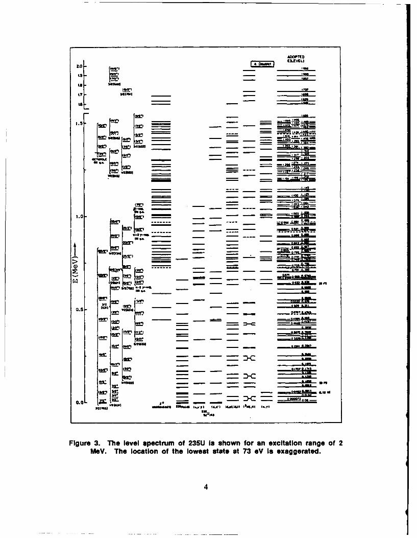
Figure 3. The level spectrum of 235U iIs shown for an excitation range of 2MeV. The location of the lowest state at 73 eV Is exaggerated.
m4,4

heavy nucleus, 23 5U. In the 2 MeV of excitation for which only one level appeared in the
carbon nucleus (Fig. 2), there are now about 100 levels (Fig. 3); and the first excited state
has an energy of only 73 eV, the lowest known first excited state of a nucleus. This level
plays a role in one of the schemes. At the current level of nuclear theory, these spectra
cannot be predicted with any precision.
Again, our goal is to study the gamma-ray laser--a conceptual device based either
on stimulation or superradiance. It is based on a transition between two nuclear levels. As
a first guess, the nuclei will be embedded in a crystal or gas having an acicular shape.
B. MULTIPOLE RADIATION
The sketch in Fig. 4 represents radiation of frequency co that is emitted when a
transition occurs between the two levels.
E 2 , J 2 , 112
E0 =-oo =E 2 -E 1 0)0
Figure 4. The two-level system.
The power that is radiated can be expressed as a series of two terms:
P(cO) = [PIm (co,E) + PIm (CoM)] (1)
0 2(1+1) 2(1+1) 2+ MIm 12Watts.
1[(21+ 1)!!2 c [W
The first terms, the electric multipoles, are due to the charge distributions in the nucleus:
*p zQ,m Jr/Y ;m (0,) P(r) d -4 e f ? ; (6 V dc. (2)f I' ,m (k'O~k) t2./ d . ()
5
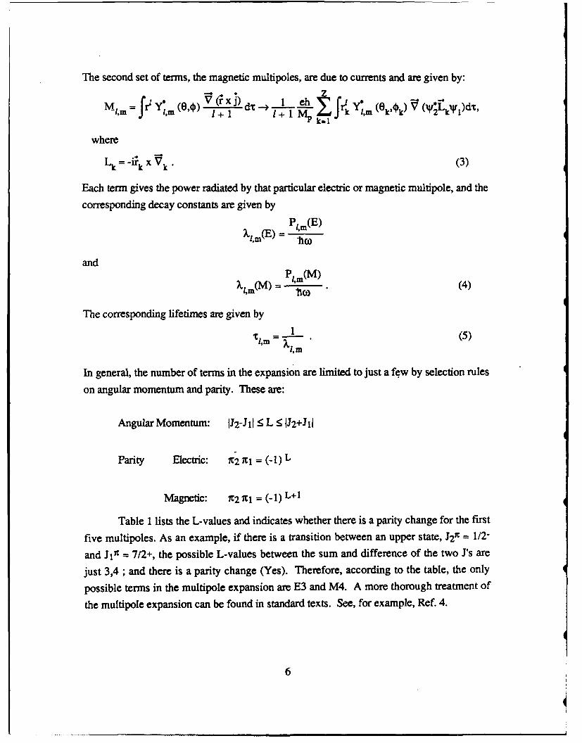
The second set of terms, the magnetic multipoles, are due to currents and are given by:
MIm = VI (,) V + dM-L ' m V (VLk)dt,
where
Lk =-irk X Vk. (3)
Each term gives the power radiated by that particular electric or magnetic multipole, and the
corresponding decay constants are given by
X (E)PIm(E )
VO
andXim() -Pt, m(M)'1M) (3)
(4)
The corresponding lifetimes are given by
1 (5)" ~ I,"-m
In general, the number of terms in the expansion are limited to just a few by selection rules
on angular momentum and parity. These are:
Angular Momentum: J2 -JiI < L < J2+JIl
Parity Electric: X2 IC = (-1)L
Magnetic: t2 R1 = (-I) L+!
Table I lists the L-values and indicates whether there is a parity change for the first
five multipoles. As an example, if there is a transition between an upper state, J2 9 = 1/2-
and J1' = 7/2+, the possible L-values between the sum and difference of the two J's are
just 3,4 ; and there is a parity change (Yes). Therefore, according to the table, the only
possible terms in the multipole expansion are E3 and M4. A more thorough treatment of
the multipole expansion can be found in standard texts. See, for example, Ref. 4.
6

Table 1. Parity Changes for Multipole Transitions
El Ml E2 M2 E3 M3 E4 M4 E5 M5
* L 1 2 3 4 5
Ai Yes No No Yes Yes No No Yes Yes No
0High multipole transitions occur frequently in the nuclear case but not in the atomic
case. This situation arises, in part, because of the differences in atomic and nuclear
structure. In the atom, electrons find themselves in the long-range coulomb field of the
* positive nucleus. The resulting eigenvalue spectrum has single particle levels which are
filled according to the Pauli exclusion principle. This procedure gives rise to particularly
stable configurations of 2, 8, 18, etc., electrons. In the nucleus, there are two types of
particles which are different charge states of the same nucleon. The nucleons are bound by
* strong short-range forces. The forces can be approximated by a deep rectangular well.
The order of the resulting levels is indicated in the left column of Fig. 5. To arrive at the
empirically observed stable neutron or proton configurations at the magic numbers of 2, 8,
20, 28, 50, and 82, a spin orbit coupling term was required; the splitting increases with L
* •and the higher J-value lies deeper. (See Ref. 5, for example.) Just below the magic
numbers 50 and 82, levels with vastly different J-values are very close. Transitions
between these would lead to high multipole radiation and, as we shall see below, these
have very long lifetimes. They are the isomers in which we are interested. Years of
* empirical observation have shown that, for odd A nuclei with an odd number of either
neutrons or protons, there are islands of isomerism for neutron or proton numbers just
below 50 and 82. Isomers are also found in other parts of the periodic table for other
reasons (e.g, shape isomers).
0
0
7
0

0
2.,4a 7 / 3 d y
2 g ."' 3d2
2g 3 p
3p 2fe.. 3o/
2 f 6 ____/__ 11l___ _2 _ 2f/L
lh @ hi
I h /2
38 5 39,/ 2 d s2d
2d 2
1gg
2p 4 2p
if ______ V
1d (Id , , 02s 1Id LV
lp 2 l_ _ '4
X 0
Figure 5. The nuclear shell model. 0
8
0

The electromagnetic lifetimes in nuclei range over many more orders of magnitude
than in atoms. A highly simplified nuclear model is used by Weisskopf (Ref. 4) to estimate
the lifetimes of the various multipoles over a wide range of energies. Actual lifetimes may
differ from these estimates by one or more orders of magnitude. Figure 6 shows graphs of
these lifetimes as a function of energy for both the electric and magnetic transitions. We are
interested mainly in the region below 100 keV. Lifetimes range from about 1 fs to about1020s.
I *S
s\s~
" "5
.5 5
Figure 6. The half-lives of electromagnetic transitions.
9
0lot.

C. LINEWIDTHS
The width of the transition is related to the mean lifetime by the simple transform
relationship:
r F = h/2x, (6)
where F is the full width at half maximum and t is the mean lifetime. For a state of high
excitation, a level may decay by many paths; each path has a partial width. Thus:
r=r.(1 +r-y2+...+r rp+r 0- + ... (7)
where each subscripted gamma is the width for the emission of that particular gamma ray orparticle and the total width is the sum of all the partial widths. For a low lying state in a
stable nucleus, the decay is generally entirely electromagnetic. It may take place either bygamma ray emission or by internal conversion (i.c.). In the case of a low lying state, we
may write:
r = r., + ri.c. (8)
Internal conversion is a process which may occur when the excitation energy of the nucleus
exceeds the binding energy of an atomic electron. In such a case, the coulomb field maymediate to transfer the excitation energy to the electron and to expel that electron rather than
to radiate away that energy by the emission of a photon. This mechanism is the nuclearcounterpart to the Auger process in the atom. The conversion width is generally setproportional to the radiation width and is written as
r = rI + ri.o. = rY + ar7 = (I + x) F. (9)
The internal conversion coefficient, a, is written as a series of coefficients for the various
shells. Thus:
a = a K + aL + aM + ... (10)
If the excitation energy is between the binding energy of the electron and the mass of the
electron, there are the following simplifying approximations:
(cK CE,L) ~ L-- Z3 174( -mc 2)
L+3-
4 2
zK (M) L 137 W (1)
10

It is clear from these approximations that the internal conversion coefficient increases withincreasing atomic number, with increasing multipolarity, and with decreasing transition
energy. These effects show up clearly in the more precise computations represented in the
graphs of Fig. 7. The coefficients for the L electrons are seen to have a similar functional
dependence on atomic number, multipole, and energy. The internal conversion coefficient
is important because it enters the formula for the stimulation cross section.
0
0
11

Z0 2 4. %
% \ % d
%
% % %%%%%
5.5: , '6 5.3I164
, I I
C .' 0 .1 A
61 M 104
-4.. .,,4 t l - \.4 . I - -*g . '
10 2 \',\,,X2 \ 11
0. LO1 0. 1 0. % L
I \ & \', I '\" \ 162. ,I - \ l:',. 10 I \% " II 'H4
I \I, ,II\ ,I ,I
10- \% 10 1'-
-0,2 0 61 Lo W0 (LI 0. * 1 $5 U La
an. Inal convion co Keffcet (w a mi tansiio in
sole Af atmi numer 3,0,acd 9.
M.3% % .- %
lit 18. % %
Lt %W ~~ %I Li .4 In
16'1 is- i> 6N
.4- - 364
am0. AS 0.0 l 0.1 0 D= am OA5 . 0.5 1.0 0.0 0050. 0.5 LO
MWx MW z Nov
Figure 7. Internal conversion coefficients for various multipole transitions innuclei of atomic numbers 30, 60, and 90.
12
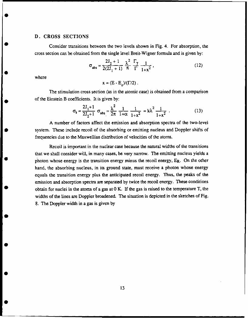
D. CROSS SECTIONS
Consider transitions between the two levels shown in Fig. 4. For absorption, the
cross section can be obtained from the single level Breit-Wigner formula and is given by:
2J 2 + 1 )2 ry 1aabs 2(2J1 + 1) It r 1+x2 '
wherex = (E - Eo)/(r/2).
The stimulation cross section (as in the atomic case) is obtained from a comparison
of the Einstein B coefficients. It is given by:
2J 1+1 2 1 1 k 2 1US 2J 2 +1 abs= 2t l+c 1+x 2 1+x2 (13)
A number of factors affect the emission and absorption spectra of the two-level
* system. These include recoil of the absorbing or emitting nucleus and Doppler shifts of
frequencies due to the Maxwellian distribution of velocities of the atoms.
Recoil is important in the nuclear case because the natural widths of the transitions
that we shall consider will, in many cases, be very narrow. The emitting nucleus yields a
* photon whose energy is the transition energy minus the recoil energy, ER. On the other
hand, the absorbing nucleus, in its ground state, must receive a photon whose energy
equals the transition energy plus the anticipated recoil energy. Thus, the peaks of the
emission and absorption spectra are separated by twice the recoil energy. These conditions
• obtain for nuclei in the atoms of a gas at 0 K. If the gas is raised to the temperature T, the
widths of the lines are Doppler broadened. The situation is depicted in the sketches of Fig.
8. The Doppler width in a gas is given by
40
13

Emission r 4. Absorption. ---
Eo-ER Eo EO +ER
Figure 8. Emission and absorption spectra for stationary nuclei. The dottedcurves represent the Doppler-broadened spectra for nuclei at the
temperature T.
A= 0 2/-" (14)
(Ref. 6) If the atoms are located in a solid lattice, the expression is modified to:
A ED c2 '~f (15)
(Ref. 7), where Teff is given by
T f(TJ [24 4 "] - 1) + 8 (16)
where C. is the specific heat and 0 is the Debye temperature.
Generally, A >> r, and the cross section for absorption (or stimulation) becomes:
o(E) = L- .o exp - (x/2A) 2 . (17)
Recoil and broadening effects are compared for a typical atomic transition and two
M6ssbauer nuclei. The results are shown in Table 2. It is obvious from the last column
that the stimulation cross section can be diminished many orders of magnitude by Doppler
broadening.
14
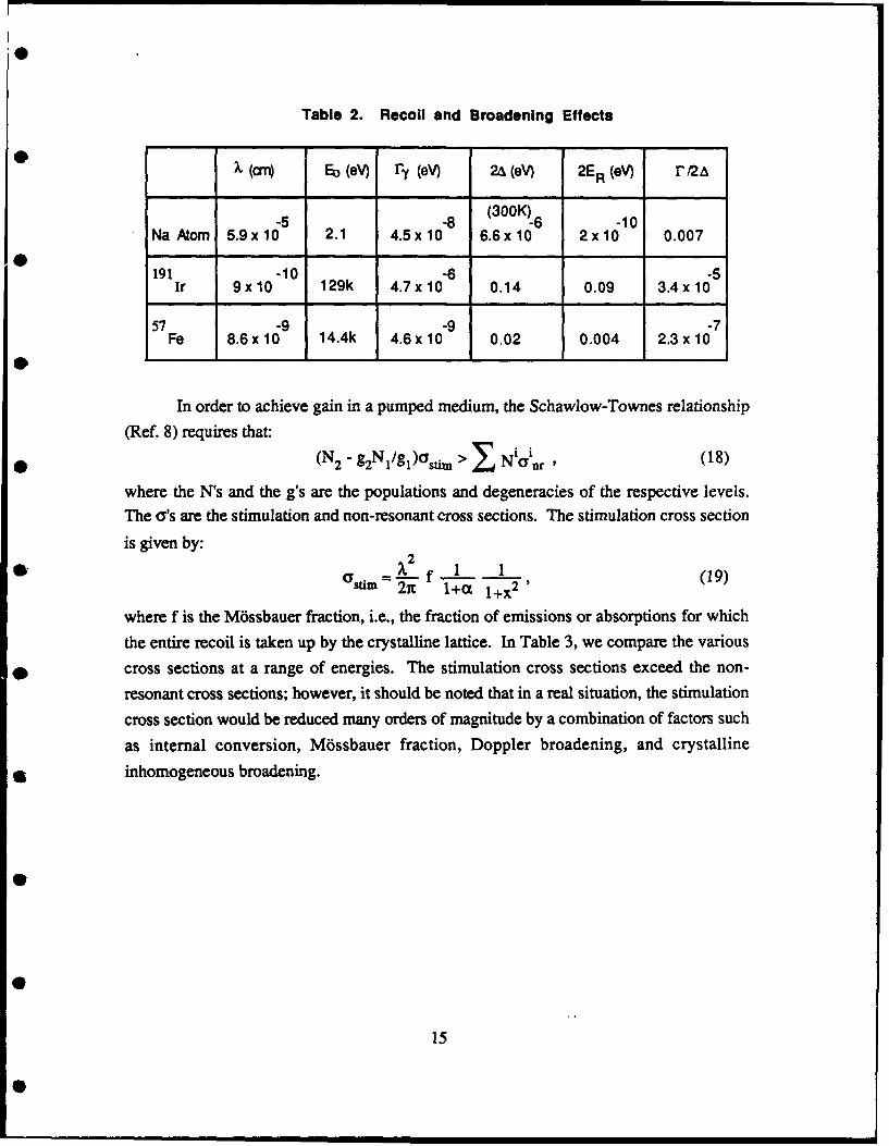
Table 2. Recoil and Broadening Effects
S(crn) ED (eV) r (eV) 2A (eV) 2ER (eV) 1/2A
-5 -8 (300K)-6 -10Na Atom 5.9 x 10 2.1 4.5 x 10 6.6x 10 2x10 0.007
191 -10 -6 -5Ir 9x10 129k 4.7x 10 0.14 0.09 3.4 x 10
57 .9 .9 -7Fe 8.6x 10 14.4k 4.6x 10 0.02 0.004 2.3 x 10
In order to achieve gain in a pumped medium, the Schawlow-Townes relationship
(Ref. 8) requires that:
* (N2 - g2N 1/g 1)astim > Niainr , (18)
where the N's and the g's are the populations and degeneracies of the respective levels.
The a's are the stimulation and non-resonant cross sections. The stimulation cross section
is given by:
xi " f I I (19)Stim1+ a 1+X2 '
where f is the M6ssbauer fraction, i.e., the fraction of emissions or absorptions for which
the entire recoil is taken up by the crystalline lattice. In Table 3, we compare the various
cross sections at a range of energies. The stimulation cross sections exceed the non-
resonant cross sections; however, it should be noted that in a real situation, the stimulation
cross section would be reduced many orders of magnitude by a combination of factors such
as internal conversion, Mossbauer fraction, Doppler broadening, and crystalline
It inhomogeneous broadening.
0
15

Table 3. Cross Sections
a a3
Eo X 2 photo compton
k Sn Pb Sn Pb
1.2 keV IOA 100b 1.5x 10⁶ 20 1.5x 10 4x10³
12 1 108 2 0 4 3104 5102 2x10³
120 0.1 106 300 2x10³ 40 100
k= [2 x(1 + a)] 1
E. STIMULATION SYSTEMS
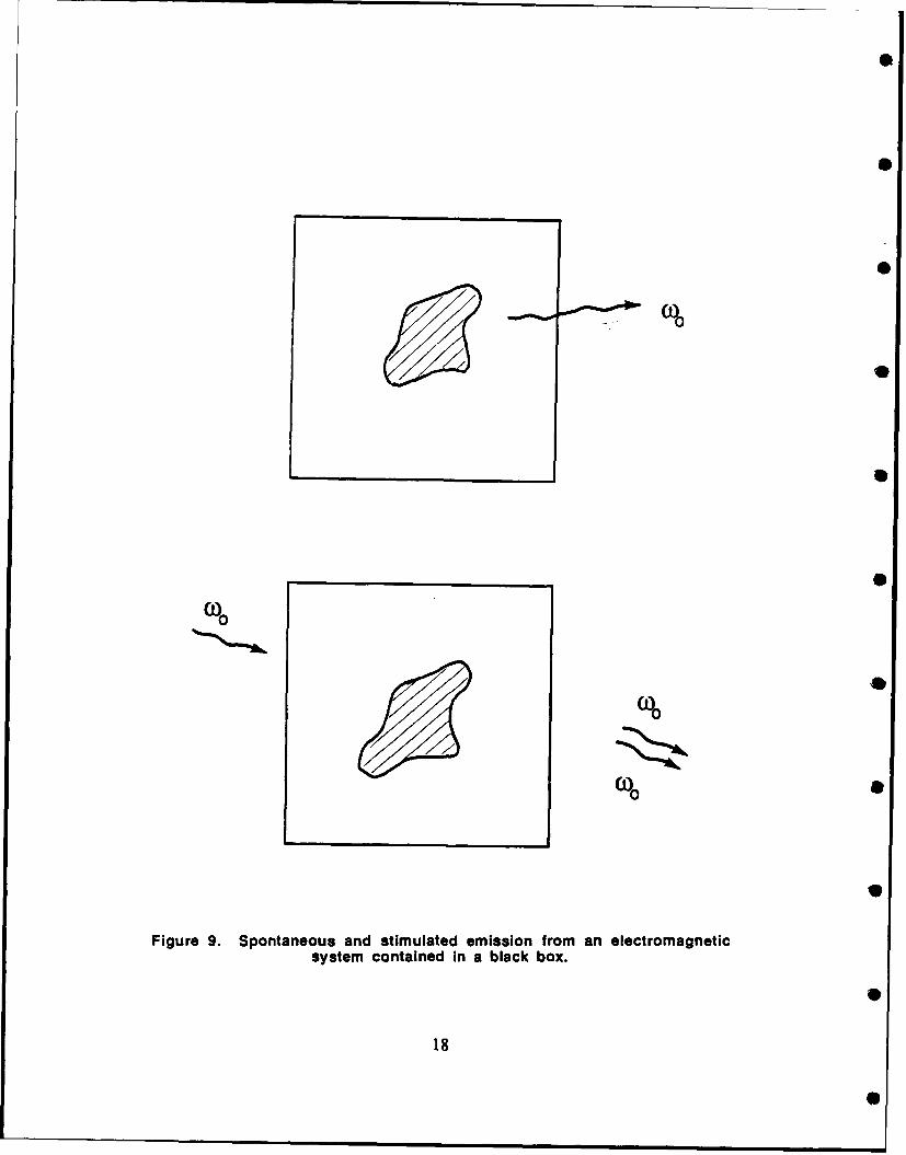
Assume that, as in Fig. 9, we have a black box containing an electromagnetic
system. The box is black only in the visible so that we cannot see into it. The system is atwo-level system, capable of being excited into the upper state by absorbing a photon ofenergy hva, and of spontaneously decaying from the upper state to emit a photon of energy
hve. If the system is in the upper state and a directed wave of energy hve passes over it, the
system may be stimulated to emit a photon of energy bye having the same linear and
angular momenta as the stimulating photon. What kind of stimulatable systems can we find
to put into the black box? We shall describe two systems.
First, consider a two-level nucleus in an atom at rest. If the nucleus is in the upper
state, it can emit a photon of energy (Eo - ER), i.e., the transition energy minus the recoil
energy. The excited nucleus can, therefore, also be stimulated to emit that photon by a
directed photon of the very same energy (E0 - ER ). However, a nucleus in the lower state
cannot absorb a photon of this energy; it can only absorb a photon of energy (E0 + ER). A
good system is therefore a gas of stationary atoms with a fraction of the nuclei in the
excited state. Let us consider only those processes occurring in a direction parallel to the
main axis of the acicular shape. Any spontaneously emitted photon can stimulate the
emission of another photon. A stationary nucleus in the lower level requires a photon of
energy (E0 + ER) to be excited to the upper state. An atom whose nucleus has just been
stimulated by a stream of photons of energy (Eo - ER) is in the lower level and is recoiling
with the energy ER towards the streaming photons with laboratory energy (Eo - ER). To
16
absorb a photon and be reexcited into the upper state, the nucleus would have to encountera photon of laboratory energy E0 . There are none. There are thus no nuclear nonresonant
processes. In this sense, the nuclear case differs from the atomic. Again, a viable system
is a gas of atoms or molecules at rest, with each atom or molecule containing the candidate
nucleus. Another system is a gas whose constituents are all moving with the same speed,v; we need merely to transform to a frame of reference in which all the atoms or molecules
are at rest and the previous situation will again obtain. In other words, one needs a systemwhose constituent particles have a velocity distribution which is a delta function.
The second example is merely another way of achieving a delta function velocity
0 distribution. The atom is now made part of a strongly bound crystalline lattice. When itsnucleus emits, the recoil is taken up by the entire crystal, not by the individual atom. Therecoil is therefore negligible. In other words, we require a solid whose nuclear emitters
undergo a M6ssbauer ef'Tct. Thus, both systems effectively have a delta function velocity
0 distribution. However, there is one difference. In the gas case, the resonance energy for
stimulation is (Eo - ER), and for absorption, (Eo + ER). An excited state population largerthan the ground state population is not required for gain. In the M6ssbauer case,
stimulation and absorption occur at the same energy, Eo; and, therefore, inversion is
0 required.
17
%S
%S
Figure 9. Spontaneous and stimulated emission from an electromagneticsystem contained in a black box.
18S
mn • C o

F. THE GAS GRASER
Two velocities immediately suggest themselves - zero and c, the speed of light.
The first, because it is achieved by going to 0 K; the second, because it is the upper limit
against which high-energy accelerators squeeze the velocity distribution.
1. The Velocity Zero.
In 1975, Hansch and Schawlow (Ref. 9) suggested that the atoms of a gas could be
slowed down to zero by irradiating the sample of gas from all six directions with a laser
tuned to the low-frequency edge of a Doppler-broadened resonance line. Atoms moving
towards the laser will see its photons Doppler-shifted towards resonance. Each absorption
will cause the atom to lose an amount of momentum equal to the momentum of the photon,h-oc. The authors calculated that with a 2852 A laser, a sample of magnesium gas could be
cooled from 600 K to 0.24 K in 30 pts. In 1983, using only one laser beam and a0 counterflowing beam of sodium atoms, several groups (Refs. 10 and 11) achieved a
stationary sample of gas with temperatures of the order of 50 mK. Refinements of this
technique at the National Bureau of Standards (NBS) and AT&T Bell (Ref. 12) have
recently led to samples of sodium gas at temperatures of about 1 mK.
Let us now consider a gas sample of molecules (mass M) having a nuclearconstituent with the transition of interest characterized by the energy EN and the lifetime TN.
The molecule also has an atomic (or molecular) transiLon which is the cooling transition; it
is characterized by the transition energy and lifetime EC and TC, respectively. Let us
assume that we are laser-cooling from a temperature T to 0 K. At T, the mean velocity of a
molecule is:
=( .1/2
*1 MlT (20)
The decrease in velocity due to the absorption of one photon of momentum AP is given by
AV = AP/M = Ec/Mc. (21)
W The number of absorptions to cool is therefore:
Nc = V/AV = (3Mc2KT)I/ 2/Ec. (22)
where c is the speed of light. One may either pump the graser (or gamma-ray laser) first
and then cool, or cool and then pump. Assume we pump first. Then, in cooling, assume
19
the atomic transition is pumped to saturation. Then, on the average, there is one absorption
every TC. The time to cool is then given by the number of absorptions times the time forone absorption, or
Time To Cool = NC Tc. (23)
To be effective and not lose the population inversion, the nuclear lifetime should obey the
relationship
'tN > Nc Tc (24)
Given the parameters
T = 300K,
M = 250, and
EC = eV,
we obtain
'tN > 1.3 x 10⁵ TC
For TC =- 10-8 s, we get:
IrN > 10 -3 S.
This situation could be a severe constraint on the graser design. However, if we cool first
and then pump, the problem may be resolved. Ultimately, the resolution depends on how
closely the temperature approaches 0 K.
2. The Velocity c.
A high-energy accelerator takes a particle from an energy Mc2 to an energy Mc 2
where
Y p(12)-1/2
and
13= V/c. (25)
The spread in energy is given byAE =(Ay) Mc 2 . (26)
The velocity spread is given by:
20

AD = (l/P) (A/9?) = Ay/- (27)
0 since 5 -- 1 for relativistic particles. In the reference frame of the beam, this expression
becomes
A1Y= Ay/y = AE/E. (28)
In order to achieve a laser, the sample has to be cooled to the point where:
r- r
or
0 AP'E 0 = F7 . (29)
For a 50 keV transition with TN = 10 8 s
Ap i012A -- 10"1
* i.e.,
AV' = 0.03 cm/s.
For current accelerators, the energy spread is many orders of magnitude away from the
above figures. For example
Van de Graaffs [5 MeV] A' = A/y= 10-5
Michigan State University Cyclotron [15 MeV protons] 10- 3
Bevelac [1 - 2 GeV/nucleon] . 10- 2
(Ref. 13). Thus, of the two velocities, zero seems the more viable.
G. THE MOSSBAUER SOLID
A group of stationary nuclei will display the usual Lorentzian shape for anabsorption or stimulation resonance, namely,
( Y = (1 + x . (30)
21

If the nuclei are in a solid, there is a Maxwellian distribution of velocities, with the
consequent Doppler broadening of the resonance. The formulae now take the shape
a = c o exp (-2X2/4), (31)
where
= F/A << 1,
and
A = E (2kTeff/Mc 2)112 ,
and Teff is a function of (O/T) and 0 is the Debye temperature. This effect, coupled with
recoil, gives the absorption and emission spectra shown in Fig. 10.
Emission Absorption
EO-ER EG EO+ER
Figure 10. Doppler-broadened emission and absorption spectra.
The peaks of the emission and absorption spectra are separated by the energy interval 2ER.
At E0 , there is a sharp peak in each spectrum that is due to the fraction of nuclei that
undergo emission or absorption with no individual recoil but have the recoil taken up by the
entire lattice. This fraction is given by the Debye-Waller factor
f=exp(-2W)=exp E- (R I+ y (ey - 1)-1 dy (32)0
The fraction can approach unity for low-energy transitions in heavy nuclei embedded in
lattices with high Debye temperatures. All the current lasing schemes demand a M6ssbauer
effect. The experimental M6ssbauer regime is approximately in the lifetime region from10-8 to about 10-4 s. That region is being extended towards longer lifetimes. The cross
section has the form:
astim = (g1/g2) Of [1 + x2] "1 (33)
22

Sometimes an additional factor is applied to take into account the broadening due to theinhomogeneities in the crystal.
H. PRESENT APPROACHES TO THE GRASER
The three major approaches at present are depicted in Fig. 11. All begin with thenuclei in a long-lived isomeric state.
LONG UPCONVERSION ELECTRON-NUCLEARLIFETIME OR COUPLING
TWO-STEP
I s o m e r -- - - - - - - - e l e c t r o nelectron
A A AzGr zGr zGr
Figure 11. The three major pumping schemes.
In the first approach, the isomer itself is used as the upper state of the lasing pair.
Because of its lifetime, given that
ft N = 6 .58 x 10"16 eV-s
= 0.159 Hz-s , (34)
the radiation width is very narrow. In general, the inhomogeneities of the crystal greatlybroaden the width and thereby reduce the effective cross section by many orders ofmagnitude. One scheme is to use nuclear magnetic resonance (NMR) techniques to remove
the inhomogeneities. Other techniques are being proposed.
In the second approach, it is assumed that there is a level nearby which can bereached from the isomer by either a laser or an x-ray source. This level has a short lifetime
and cascades down to the upper state of the lasing pair.
A two-step process is involved in the third approach. First, one must excite the
electron cloud surrounding the nucleus. Then, given compatible electronic and nuclear
23

level structures, the electronic excitation transfers to the nucleus. Again, either the upper
level of the cascading pair has been reached, or there is a cascade to it.
I. GENERAL GRASER PROBLEMS AND NEEDS
If one were to do a systems study leading to the actual design and construction of a
graser, many studies would have to be undertaken and many questions resolved. Among
them are the following:
1. Data Bases - Nuclear data bases specific to the needs of the various pumping
schemes need to be constructed. Some are in process or completed. (e.g.,
Ref. 14)
2. Producing Macro Samples of Isomers - as experiments are proposed,
samples of specific long-lived isomers will need to become available in
sufficient amounts to make crystals.
3. Crystal Fabrication - high-purity, defect-free crystals will be needed. They
will have to be very homogeneous and acicular in shape. It may be necessary to
implant the desired nuclei in a host lattice. Implanting will have to be
substitutional. Crystalline planes will have to be oriented to produce Braggscattering within the crystal to enable the establishment of Borrmann modes.
4. Radiation Damage - the crystal will contain a high density of radioactive
nuclei. Spontaneous decay of these nuclei may produce enough damage to the
lattice to decrease the Debye-Waller factor and to produce inhomogeneous
broadening. These effects need to be studied.
5. Lattice Heating - in the process of pumping the isomer, enough heat may be
generated in the crystal to either destroy the Mossbauer effect or to melt the
crystal itself. These effects are being investigated. (See Chapter II.)
6. Superradiance - many investigators assume that the graser will be a
superradiant device. Studies should be conducted to determine whether the
conditions required for superradiance can be achieved.
24
J. SCHEME-SPECIFIC PROBLEMS
Each lasing scheme brings with it its own characteristic problems:
1. Long Lifetime
* M6ssbauer Effect - Achieving the effect for long-lived transitions has been
extremely difficult. Experiments must be carried out, preferably using
candidate nuclei.
0 Inhomogeneous Broadening - The rapid suppression of this broadening is
required to trigger the energy release in this scheme. Demonstration
experiments should be undertaken in the not too distant future.
0 Internal Conversion - A long lifetime implies a high multipolarity which, in
turn, implies a large internal conversion coefficient.
2. Upconversion
• Candidate - Finding a candidate with a suitable sequence of nuclear levels may
present a very difficult problem. If one cannot be found in searches using the
current nuclear compilations, theoretical studies combined with limited
experimental searches will have to be carried out.
° Pumping - Laser pumping (especially for X > Ratom ) may encounter extreme
difficulties due to both the impenetrability of the electron cloud and to lattice
heating.
3. Electron - Nuclear Excitation
41 0 Electron Excitation - The excitation of the electron cloud may require the
deposition of sufficient energy to destroy the lattice. Experimental
demonstrations are needed.
" Atomic and Nuclear Spectra - The eigenlevel structure of nucleus and electrons0 must be compatible to enable the transfer of excitation. Here again, a mixture of
theory and experiment may be essential.
* M6ssbauer Effect - The ability to maintain the effect despite the deposition of
large amounts of energy during the excitation process must be investigated.
25

II. HEATING DURING UPCONVERSION IN A
* GAMMA-RAY LASER
A. INTRODUCTION
• It has long been hoped that very short wavelength lasers can be built by using
nuclear transitions to provide the photon (Ref. 15). Because of the large energies involved,
it has been proposed to store energy in an isomeric state, and release it in a single pulse by
upconverting to a lasing transition (Ref. 16). (See Fig. 11 of this report.) It is the purpose
* of this note to examine the heating of a sample material during such an upconversion with
X-rays. Heating is a serious concern for a gamma ray laser because, unlike the situation
with X-ray lasers, the M6ssbauer effect will be needed to keep the photons and excited
states in resonance. The examination will focus on the heating of an 57Fe sample during
* excitation of the M6ssbauer state at 14.4 keV. The arguments and physical trends do not
extend to the visible and near UV regime. These will beexamined in a separate paper.
To indicate how serious heating will be during upconversion of nuclear levels we
express the law of DuLong and Petit for specific heat capacities of metals in unconventionalunits. The standard value of 25 J/mole-K converts to 2.6x10 4 eV/atom-K. This means
that during upconversion with 10 keV photons, an energy leakage of ten parts per million
going into thermal channels would raise the temperature of the sample by 400 K. To raise
iron from absolute zero to the liquid state would require less than 65 parts per million.Resonant cross sections will be large, but nearly all the absorption must be by the nuclear
transition in order not to melt the material.
In the second section of this paper we outline the calculation, and define the needed
* parameters for the case of ideal beam--one which is of zero width and exactly tuned to the
excitation energy. Even this favorable assumption leads to damaging heating, except for
samples that are very thin compared to the radiation length of resonant photons. Such thin
samples would lead to inefficient use of the upconversion photons and increase pump
0 power requirements.
27
• | I
For non-ideal triggering beams the situation is worse, because finite beam widthwill enhance the photoelectric effect relative to the resonant excitation. Expected heating as
a function of beam width is presented in Section C, along with expected trends for variationin upconversion energy and atomic number. The results indicate a serious problem whichwould require orders of magnitude increases in both beam intensity and resolution.
It has been suggested that these problems can be dealt with by conductive cooling,(Ref. 17) or by triggering the laser in a time short compared to the crystal disintegrationtime (Ref. 18). These ideas are discussed in Section D, along with some preliminary
results. Conclusions are presented in Section E.
B. SAMPLE CALCULATION-- 5 7 FE
In this section we compute the heating during upconversion from the ground state
to the 14.4 keV state in 57Fe. We assume that the incident radiation is exactly on resonance
and neglect any detuning, and do not include any effects of heating due to decay of theexcited state. For the case calculated, there is no alternate decay channel except back to theground state, and a relatively small internal conversion coefficient. This approach results in
a very favorable case from the point of view of heating.
The essential ingredients in this calculation are the resonance cross section forupconversion of the desired state, the competing photoelectric cross section, along with theenergy loss cross sections for the resulting electrons, and finally the geometry of thesample. Knowledge of the basic bulk properties of iron is also needed. First we assume
that the nuclear excitation is exactly on resonance. The cross section for excitation-de-
excitation is:X2 reri
OR = 27r TT) 2 '(35)
where X is the wavelength, and the F's are the elastic Te), inelastic (Ji) and total widths(TT). For the case under consideration here, simple upconversion to a state which only
decays back to the ground state, the cross section simplifies to:
X"2 re (36)aR = 27 17 (36
The ratio of widths is often written 1/(1 +a), where a is the internal conversion coefficient.
This is the ratio of internal conversion to photon emission decays of the state. For the caseunder consideration, the resonant cross section is 2.38 Mb (Ref. 19). The competing
28
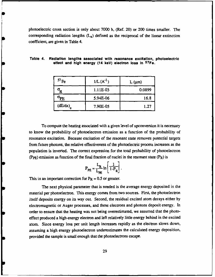
photoelectric cross section is only about 7000 b, (Ref. 20) or 200 times smaller. The
corresponding radiation lengths (Lx) defined as the reciprocal of the linear extinction
coefficient, are given in Table 4.
Table 4. Radiation lengths associated with resonance excitation, photoelectriceffect and high energy (14 keV) electron loss in 57Fe.
57 Fe i/L (A71 ) L (jpm)
C 1.11E-03 0.0899
PE 5.94E-06 16.8
(dE/dx)e 7.90E-05 1.27
To compute the heating associated with a given level of upconversion it is necessary
to know the probability of photoelectron emission as a function of the probability ofresonance excitation. Because excitation of the resonant state removes potential targets
from future photons, the relative effectiveness of the photoelectric process increases as the
population is inverted. The correct expression for the total probability of photoelectron
(PpE) emission as function of the final fraction of nuclei in the resonant state (PR) is
PPE =L In .
This in an important correction for PR = 0.5 or greater.
The next physical parameter that is needed is the average energy deposited in thematerial per photoelectron. This energy comes from two sources. First, the photoelectron
itself deposits energy on its way out. Second, the residual excited atom decays either byelectromagnetic or Auger processes, and these electrons and photons deposit energy. In
order to ensure that the heating was not being overestimated, we assumed that the photo-
effect produced a high-energy electron and left relatively little energy behind in the excited
atom. Since energy loss per unit length increases rapidly as the electron slows down,
assuming a high energy photoelectron underestimates the calculated energy deposition,
provided the sample is small enough that the photoelectrons escape.
29
This assumption of an energetic electron also leads to a minimal contribution to
heating from the atomic excitation, since relatively little energy is deposited. Tocharacterize this numerically we have taken the effective energy absorption cross section tobe lMb, which is the cross section of 100 eV photons in carbon (Ref. 21). We expect thisassumption to underestimate the true absorption. To turn this number into a rough energy
deposition, we compute EATOM = PPE E*[1 - exp (- a/2L)] where E* is the excitationenergy of the atom (the incident x-ray energy minus the ejected electron's energy) and a is
the radius of the wire. The energy deposition per atom estimated in this fashion is given inTable 5.
The energetic photoelectron will have a range in the material which varies as theenergy squared. In other words, it loses energy progressively more rapidly as it slows
down. This is observed empirically and the trend persists down to energies on the order of100 eV. We obtain a lower limit on the energy deposition by linearizing the energy loss.For photoelectrons uniformly produced in a long cylinder, with isotropic velocities, theangle averaged distance to travel to the edge of the cylinder, s, increases from the radius forparticles at the edge to x/2 times the radius for particles at the center. We can compute alower limit on the energy deposited by the photoelectron by using the minimum value of s,along with a radiation length associated with the initial energy of the particle to write
EPE = PE dx min
Since photoelectrons are preferentially produced perpendicular to the direction of motion of
the incident photon, the assumption of isotropy further decreases the estimated energy
deposition. We hope to remove these approximations in order to get a more reliable
estimate. At the moment it is worth noting that our present "estimate" is in fact a very
conservative lower bound. The energy depositions from the energetic electrons are also
given in Table 5 for a variety of iron wire thickresses, along with the total values from both
contributions. Also shown is the final temperature of the sample, assuming an initial
temperature of 100 K, and a heat capacity from the Law of DuLong and Petit. This serves
to make the numbers roughly applicable for any metal.
Now let us consider the consequences of the results in Table 5. For a variety of
radii of iron wire (first line) we have computed the effective absorption probability (second
line). All calculations assume an incident photon number equal to the number of atoms in
the sample. The fraction of the sample upconverted increases with thickness, but
somewhat slower than linearly. The fraction of photons which convert to photoelectrons
30
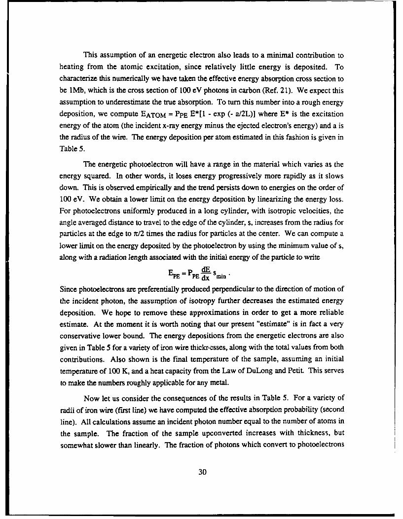
increases linearly. The photoelectric energy deposition is approximately quadratic in the
thickness. The final temperature increases dramatically with sample thickness as shown in
Fig. 12. A cold (100 K) sample of thickness 0.01 p.m would not heat up to room
temperature; however, doubling the thickness to 0.02 .m results in a final temperature
• Table 5. Heating as a function of whisker thickness for 5 7 Fe. In all calculationsthe fluence is scaled so that the photon number equals the number of atoms In
the sample.
a (gim) 0.01 0.0201 0.032 0.036 0.0375 0.04 0.05 0.0625
PR 0.11 0.20 0.30 0.33 0.34 0.36 0.43 0.50
PPE 0.0006 0.0012 0.0019 0.0021 0.0022 0.0024 0.0030 0.0037
DEPOSITION 0.03 0.13 0.34 0.43 0.47 0.53 0.83 1.29FROM PHOTO-
* ELECTRON (eV)
DEPOSITION 0.01 0.06 0.15 0.19 0.20 0.23 0.36 0.57FROM ATOM(eV )TOTAL 0.05 0.19 0.49 0.62 0.67 0.76 1.19 1.86
TF 283 840 1810 1836 1945 2137 3030 4425
.E-OUT (iJ) 0.02 0.16 0.60 0.84 0.984 1.12 2.08 3.82
4000
2000
1000-
*0.00 0.01 0.02 0.03 0.04 0.06
DIAMETER WMu)
Figure 12. Temperature increase with whisker thickness for perfectlyon-resonance beam
31

of 840 K, which is almost twice the Debye temperature. By 0.03 pln the sample has begun
to melt.
There are two difficulties with avoiding heating by going to very small samples.
First, one would have difficulties in preparation. Second, the energy stored becomes very
small. It is certainly true that using nuclear energy levels allows very efficient storage of
energy, but if only a small fraction of a small sample can be triggered, then there might be
no practical applications. Table 5 also gives the released energy, assuming the given
conversion efficiency. We see that very small energies are involved, small even compared
to a single pulse from a conventional pulsed laser.
C. UPCONVERSION WITH FINITE WIDTH BEAMS
The effect of finite beam width on the upconversion process is to make the effective
resonance cross section smaller, while leaving the photoelectric process essentially
unchanged. Synchrotron radiation may be used to provide well resolved X-rays in the 1 to
10 keV energy range, with beam widths on the order of 0.1 eV, and intensities of 5 x 10⁸
photons per burst. These pulses would typically last around 20 ns, with a pulse repetition
frequency of 1000 Hz.
In order to effectively upconvert a nuclear state, one needs a lifetime long compared
to the length of the burst, and an intrinsic width large compared to the beam spread. Since
a 10 ns lifetime corresponds to a 6.6 x 10⁻⁸ eV intrinsic width, and these quantities have a
reciprocal relationship it is impossible to simultaneously meet both requirements with
current beams. Recently, a very high resolution (0.005 eV) measurement was reported,
(Ref. 22) but this resolution improvement came at the cost of greatly reduced intensity, as
is usually the case. The most noteworthy features of these beams are that they are broad
compared to the width of the state, they are not intense enough, and finally there are
relatively few photons within one natural linewidth.
In the case of upconversion with a broad beam, it is necessary to account for the
decreased effective resonance cross section. In general, it is also necessary to account for
"bleaching" of the beam, i.e., preferential removal of photons from the resonance peak, but
for very thin samples as considered here, this effect can be neglected. For large beam
spread AE compared to the width of the state, the average cross section varies like
_FOrAE
32

The 1/AE dependence is due to the factor normalizing the beam to fixed intensity. The
constant of proportionality depends on the functional form used to represent the beam
shape. Differences in this constant are small. We used a uniform energy distribution oftotal width AE, which gives for the effective cross section
C= Go -I- arctan(-- .
The effect of finite beam width is shown in Fig. 13, where the energy deposition in
57Fe is plotted as a function of the ratio of beam spread to natural width. The target wire is
assumed to have a 0.01 rri diameter. The upconversion was set at 1 percent of the* sample. This is the minimum consistent with gain during stimulated emission. The arrow
indicates the ratio appropriate for a 0.1 eV width and a state with a 10 ns lifetime. It is clear
that there is too much energy deposition by orders of magnitude.
It has long been recognized that the Borrmann effect would be needed to reduce the
heating through atomic scattering. An optimistic assessment might anticipate a factor of
100 suppression of the photoelectric cross section. The calculations were repeated
assuming such a suppression, and the results are presented in Fig. 14. Even under these
circumstances, with current resolution, nearly 100 times the energy necessary to melt the
sample would be deposited in the process of upconverting 1 percent of the nuclei.
The energy of the calculation was chosen from the observed transition. We can
ask, what would the heating be for a lower energy X-ray transition? Naively, one might
* expect decreased energy deposition, but in fact the opposite results. With softer X-rays,
the photoelectric cross section increases dramatically, generally scaling as 1/E4 . The
resonance cross section, meanwhile, will not change much at the peak because of internal
conversion. The factor a from the ratio Fe/FT in equation (36) increases like X2 , hence the
peak cross section is essentially constant. To make matters worse, the width of the state
decreases as the energy of the transition decreases. This means that for fixed resolvingpower, the ratio of AE/F will increase with lower energy. (This change in width is not
included in the calculations presented here, since results are shown as a function of AE/F.)
In addition to lower energy x-rays producing more photoelectrons, the resulting low energy
electrons lose their energy faster on the way out of the material.
Expected heating of an iron-like material by 1 keV upconverting photons is shown
in Fig. 15 for the same target whisker as above. A beam width equal to a few times the
33

104
103. DEBYE
BEGIN BOIL102
101
0
<3 100 - -
10-lO-2
-310210"110 10 102 103 104 105 106 I0 7
AEF STATE OF THE ART RESOLUTION
Figure 13. Energy deposition in eV per atom during 1% upconversion of a0.01 Jim 5 7 Fe sample. Current beam resolution Is Inadequate to prevent
severe overheating, even with beams of insufficient intensity.
102
101 1-s DEBYEBEGI ,BO,I/100
= 10-1J
0I-10"
10
10" -..... 6 ..• "'" •,-'9 i'.- Z.. • '- ... 71,- ..
3 10"2 10"1 100 101 102 103 10 105 106 107
AE/T'
Figure 14. Energy deposition In eV per atom. Same conditions asFig. 13, but with a factor of 100 reduction In the photoelectric cross section.
Overheating is still a problem.
34

105
4 ETOMlO1 .0 DEBYE AO/
I10" BEGIN BOIL1 0
102
0 101
0 100
10"11
0
•10"3 i" -
AE/r
Figure 15. Same as Fig. 14, but for an iron-like target with a 1 keV transitionwith the same nuclear matrix elements as the 14.4 keV transition. The heating
has become much more severe because the photoelectric effect, and the rate atwhich the photoelectrons deposit energy are both dramatically increased.
natural width of the state already contributes enough energy to heat the sample above the
Debye temperature.
This situation will continue to get worse to energies below 100 eV. It may begin to
0 improve at that point because dE/dx of tne photoelectrons begins to decrease.
Nevertheless, the heating is probably intolerable for any photons above the minimum
ionization threshold.
D. LOOPHOLES
In this section we discuss two proposed loopholes, conductive cooling, and time
considerations which might allow triggering of a gamma-ray laser, despite the heating.
Conductive cooling of the sample requires that the sample be embedded in or against a
* material which has a high thermal conductivity, high heat capacity, and low photoelectric
cross section. We considered carbon as a candidate heat sink. (Other materials will be
considered in the future.) We took the Debye temperature as a target temperature, and
computed the energy needed to raise graphite from around 100 K to 440 K, the Debye
*0 temperature of iron. Then, for given AE/F we computed the energy deposited per iron
35
atom (assuming the Borrmann effect, as in Fig. 14), and converted that to the number of
carbon atoms needed per iron atom, and a thickness for the carbon backing. We then
computed the direct heating of the carbon backing due to the photoelectric effect in the
backing. The carbon was also assumed to be in a crystal with a factor of 100 reduction in
the photoelectric cross section due to the Borrmant, effect. No account was taken of
photoelectrons from one material passing into and heating the other.
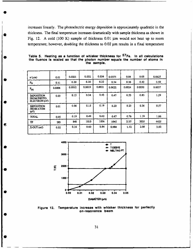
Despite these optimistic assumptions, the results shown in Table 6 indicate limited,
if any, help from the heat sink. For 0.1 eV resolution beam, we find that the needed
carbon heat sink is sufficiently large that despite the lower photoelectric effect, it would be
heated above the temperature of the iron, and aggravate the problem. As the postulated
beam is improved, the carbon begins to lower the temperature of the iron. Nevertheless,
there appears to be no appreciable region where this approach would be helpful. It should
be stressed that this again is a conservative calculation, and that substantial heating of the
carbon from photoelectrons produced in iron, and vice versa should be expected. On the
other hand, berylium or boron, because of their even smaller photoelectric cross sections
might be better in this application as heat sinks. Future calculations will address this
question.
Table 6. Heatsink temperature (K) due to photoelectric effect In the heatsinkitself. Size of heatsink set by excess heating (above TDEBYE) in 0.01 im Fe
sample, initially at 100 K.
AE/F ED T (K) a(jin) ED (C) T (C)
106 23.0 0.32 34.0 Hotter105 2.3 5346 0.1 0.49 Cooler104 0.23 985 0.032 0.0059 320*103 0.023 189 0.01
*Insufficient for cooling of entire sample below TDEBYE.
Another approach to evading the difficulties presented by heating is to attempt to get
the coherent radiation out of the lasing medium before the heat leads to disintegration.
Generally, the lifetimes under consideration are on the order of 10 ns. If they are
much shorter, then pump power problems are believed to become insurmountable. The
question then is, will the crystal hold together well enough for both the M6ssbauer and
36

Borrmann effects to apply for a time on the order of 10 ns. We believe that this is atpresent an unanswered question. From the results of Ref. 23 it is clear that the time
required for break up of a diffraction pattern is a very strong function of the amount of
energy deposited. The data are plotted, along with a simple power law fall-off, in Fig. 16.,The best fit was t = 6723 x -6.13 ps, where x is the energy absorbed divided by the energy
required to melt the sample.) This time decreases very rapidly with deposition energy. If
barely enough energy is deposited for melting of the sample, the crystal integrity times may
be on the order of a few ns in aluminum. If three times the melting energy is deposited, the
crystal integrity time extrapolates to a few ps. Since diffraction depends on fixed position,whereas the M6ssbauer effect relies on low velocity, the M6ssbauer effect would probably
be lost on a time scale short compared to that for the diffraction pattern. Characteristictimes for electron transit, even at low energy, are quite short compared to the likelylifetimes. (A 100 eV electron travels at 6 pips.) The combination of crystal disintegration
times and electron transit times both short compared to the relevant nuclear lifetimes makes
lasing before disintegration appear improbable. Further analysis will include electron-
photon collision times and atomic excited state photon and auger decay times.
104
0 TimetoMelt I
0a.
a
< 102_J
1011.0 1.5 2.0 2 5 3.0
ENERGY ABSORBED/ENERGY TO MELT
Figure 16. Crystal disintegration times from Ref. 23 as a function of depositedenergy. The energy deposition is in units of the energy required to melt the
sample.
37

E. CONCLUSIONS
X-ray upconversion of a nuclear isomer to a suitable lasing state is going to be an
extremely difficult undertaking. Intrinsically, leakage of a very small fraction of energy
into thermal channels, primarily via the photoelectric effect, will destructively heat thesample. Current X-ray sources are orders of magnitude too broad in energy, as well as too
weak to accomplish the task. It appears that the time scales of the destructive heating are
short compared to nuclear decay times. A preliminary examination indicates that
conductive cooling of the sample is not a workable option. Photoelectric heating of the
heatsink itself prevents its utility.
From the above discussion it appears that two courses of action are called for.
First, within the context of the upconversion approach to building a gamma-ray laser, much
more attention should be paid to possible triggering beams. Furthermore, other approaches
not relying on upconversion should be receiving greater attention.
38

III. AN INVESTIGATION OF THE DESTRUCTION BYINHOMOGENEOUS BROADENING OF RESONANCE IN
ISOMERIC CRYSTALS AND ITS RESTORATION BYSPECIAL EFFECTS
A. INTRODUCTION
The first concepts for developing a gamma-ray laser were based on stimulated
emission from isomeric crystals (Ref. 24). It was natural to examine the possibility of
stimulated emission in long-lived nuclear transitions after (1) the development of the maser
and laser showed that inversion was possible and stimulated emission could be used to
generate and control coherent microwave and optical radiation (Ref. 6) and (2) the
discovery of the Mossbauer effect showed that nuclear resonance fluorescence could be
easily observed under well-defined conditions (Ref. 25). The possibility of using nuclearisomeric crystals as the lasing media, the isomeric level being the upper lasing level, was
desirable because it would allow the use of lower pumping powers for the inversion.
However, soon after the discovery of the M6ssbauer effect, experimental
exploration of this phenomenon of nuclear resonance revealed that observing the effect with
nuclei of longer lifetimes (narrower natural linewidths) become increasingly more difficult
(Ref. 13). The reason for this is that nuclei at different sites in the crystal experienced
slightly different electric and magnetic fields because of crystal irregularitY-s, impurities,
and even different nuclear spin orientations of nearest neighbors. These effects,
collectively referred to as inhomogeneous broadening of the M6ssbauer line, will be
discussed in more detail later. For the present, it is sufficient to point out that, in order to
use isomeric levels in a lasing transition, the inhomogeneous broadening effect on the
resonance has to be reduced. Two concepts have been proposed to do just this.
One concept for producing a gamma-ray laser is based on the ability to remove the
effect of the coupling which causes inhomogeneously broadened nuclear resonance lines in
the isomeric crystal. The technique proposed for eliminating the effects of nuclear dipole-
39

dipole interaction, a major contributor to the inhomogeneous broadening, is a well-known
RF pulsing technique used in high-resolution nuclear magnetic resonance (NMR) 0
spectroscopy (Ref. 26) and theoretically shown to be applicable to M6ssbauer spectroscopy
(Refs. 27 and 28). Such techniques have been used to reduce the inhomogeneous
broadening in NMR work by up to four orders of magnitude (Ref. 29).
In another concept, the individual narrow lines are homogeneously broadened. 0Overlap of lines and resonance is achieved (Ref. 30) because as a result of this operation all
the nuclei in the sample have the same broad lines, which are greater than the
inhomogeneous broadening.
Level Mixing Spectroscopy (LEMS) is based on the principle of homogeneous line •
broadening (Ref. 31). Recently, the application of this technique to a perturbed angular
correlation (PAC) type of experiment led to a measurement of a "resonance" in 109Ag.*The effect of this level mixing on a M6ssbauer type of experiment has been discussed in
recent publications (Refs. 30, and 32). Experiments are being planned to verify these 0
concepts (personal communication, P. Boolchand).
Another way of obtaining homogeneous broadening of resonance lines which leads
to greater overlap between source emissions and the absorber cross section is through •
relaxation phenomena or time-dependent hyperfine interactions (Ref. 33 and 34). These
homogeneous broadening effects are well known in the M6ssbauer community. Their use
in recovering the resonance destroyed by inhomogeneous broadening in the source and
absorber experiment has to be investigated. 0
In this paper we examine the utility of line shifting and broadening techniques to
increase the resonance effect in inhomogeneously broadened systems.
B. RESONANT LINESHAPES AND MOSSBAUER EXPERIMENTS 0
The interaction between a source and an absorber in a Mossbauer experiment can be
described in terms of an emission line and an absorption cross section. If a detector is
located as shown in Fig. 17, then for a thin absorber which does not appreciably change
the beam line profile, and assuming only resonant absorption, 0
Strictly speaking this is not a resonance in the Massbauer sense.
40
0

SOURCE ABSORBER DETECTOR
Figure 17. M6ssbauer transmission experimental geometry.
the detected loss in the total photon count, ID, because of the presence of the absorber is
given by* t2
ID= fdt fI(EF,S) na(E,F)dE, (37)ti -.-
where n is the number of resonant nuclei in the beam per cm2 , and the measurement is
performed during the time interval t2 - tl. I (EF,S) is the source radiation lineshape and
o(E,l") is the resonant cross section of the nuclei in the absorber.
The source lineshape is given by0 N io 1" f,
0(E,,S) Pi (i) 2c 2 (38)[E-(E0-ei) - S]2 + (r/2)2
where I0 is the flux of photons from the source in cm -2 s-1 in the direction of the detector,
* Eo is the resonant energy of an unperturbed nucleus, Ei is the perturbation of the energy of
nucleus i due to the environment, S is the Doppler shift due to the relative motion of the
source and absorber nuclei and is given by S = v/c Eo, with velocity v where c is the speed
of light, F is the natural linewidth* and fs is the recoil-free fraction in the source. It is
* r is the total level width which is a sum of the level widths of all the contributng processes to thelevel decay.
41

assumed in equation (37) that the integration time is short enough that 10 can be taken asconstant.
The distribution of nuclear environments is assumed to be normal with width A so
that the probability of finding a nucleus with energy ei displaced from the resonance energy
Eo in a width Aei is given by
Pi,(d nIAe Aci. (39)
Similarly, for the effective cross section of the absorber we havexN aoor fa
a(E,r) = 2_, f2 (40) 02 +
Where ao is the cross section on resonance and is given by
)2 21e+1 10 2n" 21 +1 l+cc
g
le and Ig are the nuclear spin quantum numbers of the excited and ground states,
respectively, a is the internal conversion coefficient of the transition, X is the nominal
wavelength of the gamma-ray, Fy is the photon absorption partial width. Figure 18 is a
schematic representation of the resonance effect when Ei = o. The source and absorber
nuclear resonance energies are given by Es and Ea, respectively, and AE = Ea - Es. The
integral over energy given in equation (37) is represented by the shaded region in Fig. 18.
Es Eg
Figure 18. Resonance condition for source and absorber
42
w m m m
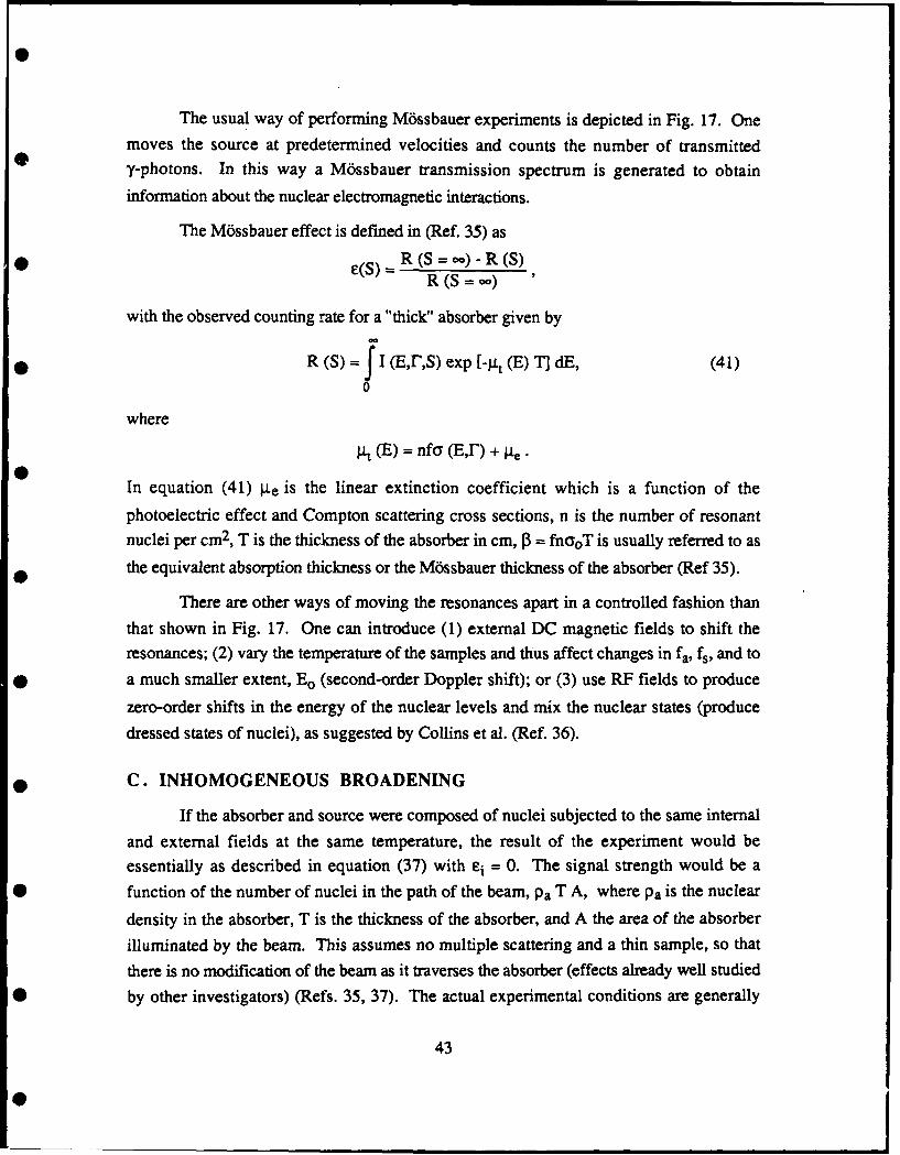
The usual way of performing M6ssbauer experiments is depicted in Fig. 17. One
moves the source at predetermined velocities and counts the number of transmitted
7y-photons. In this way a M6ssbauer transmission spectrum is generated to obtain
information about the nuclear electromagnetic interactions.
The M6ssbauer effect is defined in (Ref. 35) as
* e(S) =R (S = -)- R (S)R (S = co)
with the observed counting rate for a "thick" absorber given by
R (S) f Ji (E,r,S) exp [-g, (E) TI dE, (41)0
where
t (E) = nfa (E,T) + te .
In equation (41) g.e is the linear extinction coefficient which is a function of the
photoelectric effect and Compton scattering cross sections, n is the number of resonantnuclei per cm2 , T is the thickness of the absorber in cm, 0 = fnaoT is usually referred to as
the equivalent absorption thickness or the M6ssbauer thickness of the absorber (Ref 35).
There are other ways of moving the resonances apart in a controlled fashion than
that shown in Fig. 17. One can introduce (1) external DC magnetic fields to shift theresonances; (2) vary the temperature of the samples and thus affect changes in fa, fs, and to
* a much smaller extent, Eo (second-order Doppler shift); or (3) use RF fields to produce
zero-order shifts in the energy of the nuclear levels and mix the nuclear states (produce
dressed states of nuclei), as suggested by Collins et al. (Ref. 36).
* C. INHOMOGENEOUS BROADENING
If the absorber and source were composed of nuclei subjected to the same internaland external fields at the same temperature, the result of the experiment would beessentially as described in equation (37) with ei = 0. The signal strength would be a
* function of the number of nuclei in the path of the beam, Pa T A, where Pa is the nuclear
density in the absorber, T is the thickness of the absorber, and A the area of the absorber
illuminated by the beam. This assumes no multiple scattering and a thin sample, so thatthere is no modification of the beam as it traverses the absorber (effects already well studied
0 by other investigators) (Refs. 35, 37). The actual experimental conditions are generally
43
*
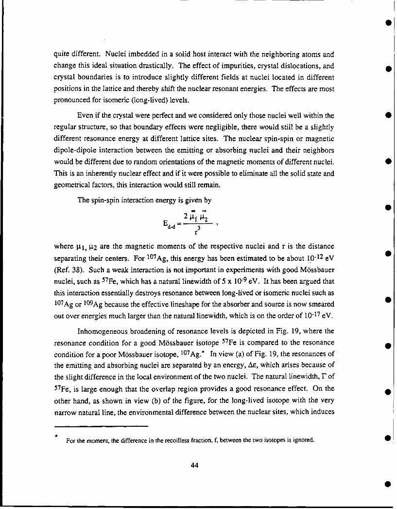
quite different. Nuclei imbedded in a solid host interact with the neighboring atoms and
change this ideal situation drastically. The effect of impurities, crystal dislocations, and
crystal boundaries is to introduce slightly different fields at nuclei located in different
positions in the lattice and thereby shift the nuclear resonant energies. The effects are most
pronounced for isomeric (long-lived) levels.
Even if the crystal were perfect and we considered only those nuclei well within the
regular structure, so that boundary effects were negligible, there would still be a slightly
different resonance energy at different lattice sites. The nuclear spin-spin or magnetic
dipole-dipole interaction between the emitting or absorbing nuclei and their neighbors
would be different due to random orientations of the magnetic moments of different nuclei.
This is an inherently nuclear effect and if it were possible to eliminate all the solid state and
geometrical factors, this interaction would still remain.
The spin-spin interaction energy is given by
2 j p'2E d-d 3 32
r
where I.t1, 1.2 are the magnetic moments of the respective nuclei and r is the distance
separating their centers. For 10TAg, this energy has been estimated to be about 10-12 eV
(Ref. 38). Such a weak interaction is not important in experiments with good M6ssbauer
nuclei, such as 57Fe, which has a natural linewidth of 5 x 10⁻⁹ eV. It has been argued that
this interaction essentially destroys resonance between long-lived or isomeric nuclei such as
107Ag or 109Ag because the effective lineshape for the absorber and source is now smeared
out over energies much larger than the natural Iinewidth, which is on the order of 10-17 eV.
Inhomogeneous broadening of resonance levels is depicted in Fig. 19, where the
resonance condition for a good M6ssbauer isotope 57Fe is compared to the resonance
condition for a poor M6ssbauer isotope, 107Ag.* In view (a) of Fig. 19, the resonances of
the emitting and absorbing nuclei are separated by an energy, AE, which arises because of
the slight difference in the local environment of the two nuclei. The natural linewidth, r of5 7Fe, is large enough that the overlap region provides a good resonance effect. On the
other hand, as shown in view (b) of the figure, for the long-lived isotope with the very
narrow natural line, the environmental difference between the nuclear sites, which induces
*i
For the moment, the difference in the recoilless fraction, f, between the two isotopes is ignored. 01
44

the energy shift Ae, destroys the resonance condition between emitter and absorber. Toproperly describe this situation, ej * 0 has to be introduced into the equations.
SHORT-LIVED ISOTOPE LONG-UVED ISOTOPE57F. 107AQ
T, 1010 - 7 3, 71 44*
Figure 19. Resonance conditions for short- and long-lived isotopes. For* comparison we show in (a) 57Fe a good M6ssbauer Isotope but difficult to invert
because of the short lifetime and in (b) 107Ag, relatively more easy to invertbecause of the long lifetime but not a good M6ssbauer isotope because of the
narrow lines.
This parameter can be conveniently divided into three parts so that
"i = F-Ci + eni + Eei
where eci is the energy shift in the resonance of nucleus i due to crystal imperfections,
impurities, boundary effects, Eni is the energy shift in the resonance of nucleus i due to
* nuclear spin effects from neighboring nuclei and, Cei is due to external effects such as
gravitational differences at different nuclei sites.
The average effect on M6ssbauer experiments of this inhomogeneous line
broadening due to the energy shifts Ei can be approximated by an effective increase in the
linewidth of the source or absorber by a factor (1 + a) where a is called the
"inhomogeneous broadening parameter" (Ref. 13). The effect on the threshold condition
for lasing is drastic, because the factor (1 + a ) multiplies the total linewidth of the nuclei in
the lasing medium, thus effectively reducing the resonance cross section.
45

In the line-narrowing concept for developing a y-ray laser (Ref. 39), the parameter a
has to be substantially reduced. It is assumed that the line-broadening terms due to crystal
imperfections and impurities can be reduced by proper geometry, size, and crystal
prepartion and that the nuclear spin interaction term can be reduced by an appropriate
sequence of RF pulses, as in high-energy resolution NMR. Alternatively, a technique forhomogeneously broadening the individual resonance lines such as Level Mixing
Spectroscopy (LEMS) can be applied to reduce a. The two mechanisms for achieving
resonance in the sample, or more precisely getting more nuclei on resonance are depicted in
Fig. 20. In case one the narrow lines are shifted toward E, the unperturbed energy, and in
case two the lines are broadened so that the effective linewidth is greater than the energy
producing the inhomogeneous broadening. The total magnitude of the required effect is
dependent on other isomer characteristics, as discussed in Ref. (39).
r0
9-21-87-16 (a) (b)
Figure 20. Two different approaches for obtaining resonance with long-lived isotopes (destruction of the effect of inhomogeneous broadening) in (a)
an RF pulsing technique causes a line shift and in (b) through cross fields levelmixing, or relaxation homogeneous broadening of lines causes resonance
overlap.
The inhomogeneous broadening term a will be reduced naturally when either the
ground or excited nuclear states have zero spin, because then either gl or g2 will be zero.
Also, if the nuclei in the crystal are all initially in the excited state the effect of this term will
46
0

be greatly diminished in the early stages of laser pulse evolution because of the relatively
small number of nuclei in the ground state.
D. THE MOSSBAUER RESONANCE IN THE PRESENCE OFINHOMOGENEOUS BROADENING
Assuming the source lineshape, absorber cross section, and distribution of nuclear
environments as given by equations (38, 39, and 40, respectively) the intensity of the beam
I' absorbed by a thin absorber* (Eo = 0 without loss of generality) is given by
I'(J7,a,s) = na 2.,2 e' ' e" ' AeiAe
*4/tA 1A2 i j2, 2 2 2' (42
x -dE (r) 117 (42)
. (E-C-S) 2 + (1/2)2 (E-E)2 + (J/2) 2
where Ns, Na are the total number of sites with energy shifts ei and ej in the source and
absorber, respectively, and where na is the number of nuclei per cm 2 in the absorber.
Converting the sum to an integral one has (see Appendix A)
I'(F,A,S) = -- Io,%(f.A) na Re (eZ ) erfc(Z) (43)
where
A 2 = A 2 )/2 , and Z = (r +iS)/f/ A.
The -maximum normalized resonant absorption (S = 0) is given by
I"(r,A) = '(F,A,S = 0)/ (Llonao) (44)
2 ex erfcx], wher x
A thin Mossbauer absorber is one for which the lineshape of the beam passing through the absorber isnot sufficiently modified to show saturation effects. This is discussed in Appendix B, where it isshown that for the MOssbauer thickness b < 10 the ratios of the intensities of the lines in the spectrumare close to their theoretical values and saturation effects are small. Under such conditions, it isappropriate to use equation (37) for the absorption calculations instead of the general expression givenin equation (41).
47
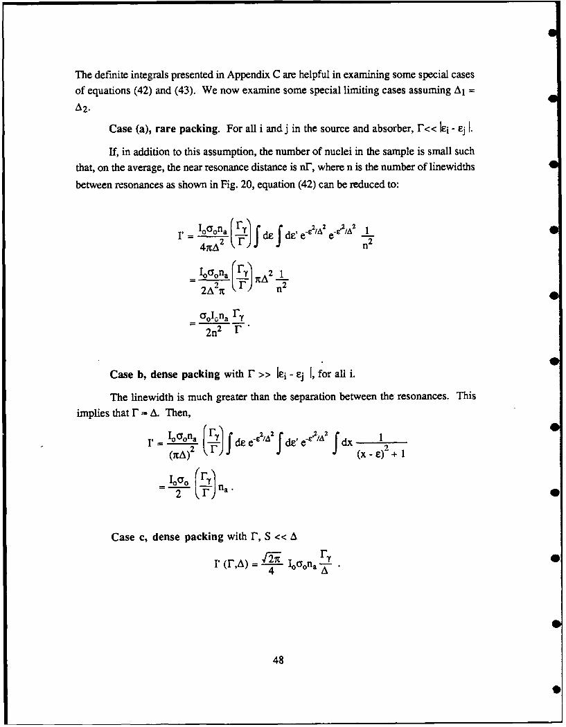
The definite integrals presented in Appendix C are helpful in examining some special cases
of equations (42) and (43). We now examine some special limiting cases assuming A1 =
A2.
Case (a), rare packing. For all i and j in the source and absorber, r<< Iei - ej I.
If, in addition to this assumption, the number of nuclei in the sample is small such
that, on the average, the near resonance distance is n", where n is the number of linewidths
between resonances as shown in Fig. 20, equation (42) can be reduced to:
11 IoO'ona yS de de' e-e2/A2 e-c2 A2 1
I'=)_ Io~on a rF'/A21
2 A2 ,1 n 2 4
_-olona "T
2n2 "
Case b, dense packing with F >> Ie-i - ej I, for all i.
The linewidth is much greater than the separation between the resonances. This
implies that F = A. Then,
1, Ion _ f d e 2/A dF, e-',/ dx
(ItA) 2 (x -E)2 + 1
2 (Er)
Case c, dense packing with F, S << A
I' (F,A) = Io2 o na .
48

Case d, dense packing with F or S >> A
0 ~L IooyonarFv* r'(F,A) --~ oaF
2(1 +S2 )
The normalized maximum resonance absorption, I" (,A) calculated from equation (44) is
plotted in Fig. 21 as a function of /A for the case F/F= 1, and in Fig. 22 as a function of
* A/F for various values of F/.r For inhomogeneous broadening on the order of the natural
linewidth, F/A = 1, good absorption is obtained, indicating the presence of a strong
M6ssbauer resonance between the source and absorber. For A >> F, the absorption drops
linearly.
2 OL75-I-
2
n0 C~0J
UI-4
4Zo 130
* 0.25
0 0
00 510 1
RATIO OF NATURAL LINE WIDTH TO BROADENED DISTRIBUTION
9-21-47-11
Figure 21. A plot of the maximum normalized resonance absorption I"(calculated from equation (44), assuming r"/" = 1) as a function of r/A
49
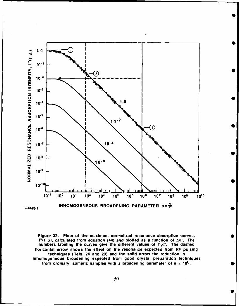
1.0 3
L.I
- 10-3'
P 10-4 1.wJ II- '
C io-2
LU
-- " 10. I 10.2
Z I
14ZoU) 10- 10-4
w~n I
w1 10.8 10
N I-IN 10. 6
2 0, - I1.
0
,, I
10.10-
10.1 100 101 102 1 104 10S 106 107 108 109 1010
4-2888-3INHOMOGENEOUS BROADENING PARAMETER a=A
Figure 22. Plots of the maximum normalized resonance absorption curves,l"(r,A), calculated from equation (44) and plotted as a function of A/fl. Thenumbers labeling the curves give the different values of rj/r. The dashed
horizontal arrow shows the effect on the resonance expected from RF pulsingtechniques (Refs. 26 and 29) and the solid arrow the reduction In
inhomogeneous broadening expected from good crystal preparation techniquesfrom ordinary isomeric samples with a broadening parameter of a = 106.
50
,.I

E. DECREASING THE EFFECT OF INHOMOGENEOUS BROADENINGIN MOSSBAUER EXPERIMENTS
Inhomogeneous broadening results from nuclear environments at different lattice sites
producing different shifts in the resonance energies Ei of the respective nuclei. This effect
reduces the overlap in the source and absorber lineshapes. In order to increase the overlap,
0 one can either shift the individual resonances back to a common energy E0 , as shown in
Fig. 20(a) or broaden the lines homogeneously without shifting, as shown in Fig. 20(b).
It may be possible to perform a modification of the lineshape which results in both effects
as shown in 20(c). Two approaches to overcome the inhomogeneous broadening effect on
0 M6ssbauer experiments have been presented in the literature. Generally, the first step in
both techniques is the preparation of a crystal of the isomer, with
minimum deformations. However, even in an ideal crystal the dipole-dipole interaction
between non-zero spin nuclei will persist and produce different energy shifts at different
0 nuclear positions.
In the first approach, one attempts to reduce the effect of the dipole-dipole
interaction by the technique of pulsed RF fields. This technique was originally developed
for high-resolution NMR spectrometry and is incorporated into commercial instrumentation(Ref. 26). It has been claimed to reduce inhomogeneous linewidth in nuclear ground state
spin transitions by as much as 104 (Ref. 29) and has been examined theoretically as a
procedure for reducing the inhomogeneous broadening in M6ssbauer effect experiments
(Ref. 27). It reduces the inhomogeneous linewidth by breaking the effect of the dipole-dipole interaction through rapid reorientation of the spins, thus effectively shifting lines
toward the same resonance energy Ae-4Ae'---0 for all i) as shown in Fig. 20(a). With
reference to Fig. 22, the resulting decrease in A would move the operating point from point
(1) to point (2) on the curve, reflecting a decrease in A/F of I04. To approach the desired6 operating point (3) a further reduction in A would have to be achieved by proper
preparation for the crystal to minimize the effect of impurities and crystal imperfections.
The second technique is depicted in Fig. 20(b). Instead of shifting the resonance
0 energy at each nucleus by -el to coincide with the base nuclear resonant energy [see
equation (42)] the second technique homogeneously broadens each line to obtain greater
overlap in the lineshapes as shown in Fig. 20(b). The homogeneous line broadening can
be achieved by various means. In particular by working in the region of level crossings,
51

mixing of sublevels can provide enhanced transitions between sublevels leading to
homogeneous broadening of lines.
The reduction of the overlap of nuclear resonance lines in an inhomogeneously
broadened crystal is depicted in Fig. 23(a). Only some of the lines are shown for clarity
presentation. Partial recovery of the overlap due to line shifts, homogenous broadening,
and a combination of the two effects is depicted in Fig. 23(b) through 23(g).
Level mixing effects have been used in Level Mixing Spectroscopy (LEMS) to
obtain resonances in perturbed angular correlation experiments in 109Ag (Ref. 31). Such
resonances have not been seen before in the Ag transition and are not seen outside of the
level crossing region, indicating the importance of the shortened coherence time in these
experiments. In M6ssbauer experiments, on the other hand, the value of the resonance
cross section determines the size of the effects. If this broadening is done at the expense of
the maximum cross section on resonance, then as can be seen from equations (40) and (43)an increase in the total width F will not be effective in producing an increase in resonance
as F -+ A because the factor Fy/,F in equation (44) will still dominate even though F/A the
argument in the exponential and error function factors increases to values greater than one.
The homogeneous broadening produces overlap of lines but this is not sufficient to get
good absorption because of the factor fr". The mechanism (LEMS) has to induce level
shifts in addition to homogeneous broadening in order to be effective.
Another way of obtaining homogeneous broadening is through relaxation effects
which are clearly exhibited in Mossbauer effect spectra. Figure 24 shows Mossbauer
transmission spectra of Ferrichrome A, a paramagnetic compound, at several temperatures.
The spectra range from a well-defined, six-line pattern with narrow lines approaching the
natural linewidth at low temperatures to a complex broadened pattern with linewidths
determined by the electron spin relaxation time and the magnitude of the interaction to a
single motionally narrowed peak, with the hyperfine pattern destroyed at high
temperatures.
52
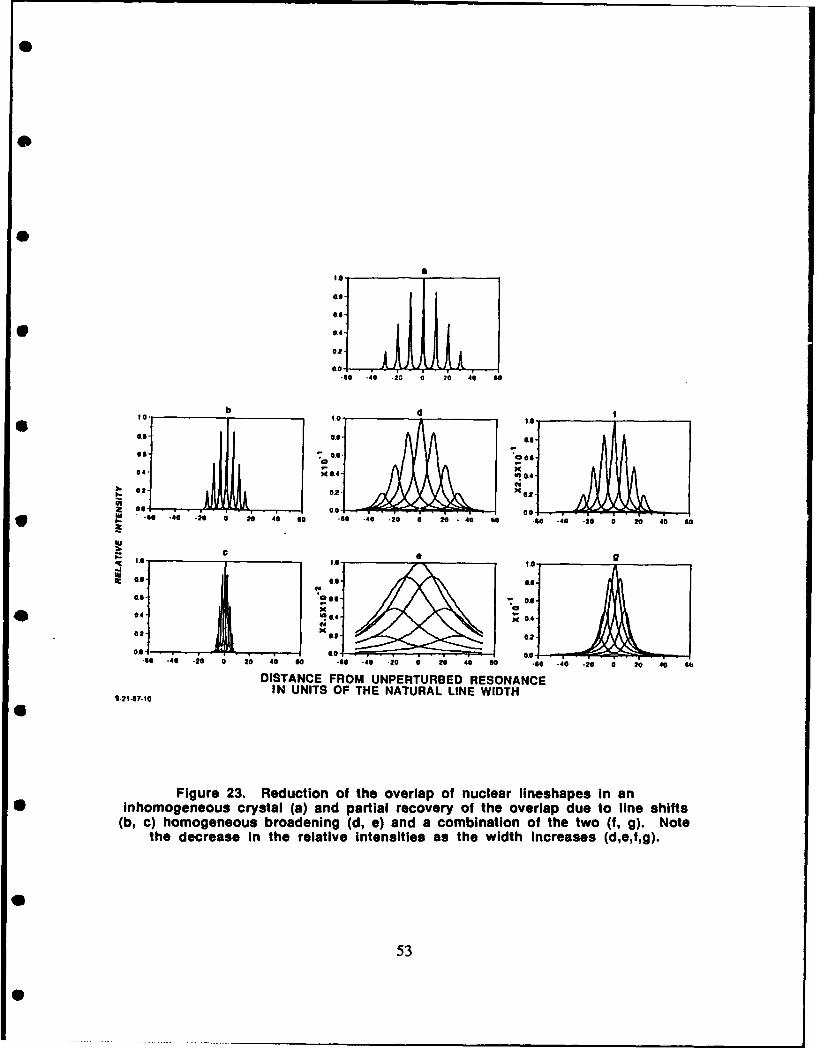
.
00.4
0.20.]I
.60 -40 -20 0 20 40 60
to. O.0od I.e.
o &aS '0 . o.G6
04 -- 0.4 x
40.! u0.40202 "J24.0.202
- .: - 20 - 2• 4 6o 0 - o 40 _ -20o 20-40o .;o 0 0 2;40 , o
Le Is sI 0.6 0.6-
0.-. V! 0.4 X 0A 4
0C40x 0 02
40 -40 -20 0 20 40 00 -- 0 -i0 -;G -20 0 20 40 66
DISTANCE FROM UNPERTURBED RESONANCEIN UNITS OF THE NATURAL LINE WIDTH
0-21-07-10
Figure 23. Reduction of the overlap of nuclear lineshapes In an• inhomogeneous crystal (a) and partial recovery of the overlap due to line shifts
(b, c) homogeneous broadening (d, e) and a combination of the two (f, g). Notethe decrease in the relative intensities as the width increases (d,e,f,g).
53

FASTERRELAXATION
S FASTRELAXATION
SLOW T.,.
RELAXATION
ENERGY
Figure 24. Nuclear lineshape modification due to electronic relaxationwithout change in the nuclear lifetime: experimental results in Ferrichrome A
are shown, together with the theoretical calculation. Source of data Is Ref. 34.
54

S
Figure 25 shows a hypothetical source absorber overlap of lines with narrow lines
in Fig. 25(a) and broadened lines in Fig. 25(b), and 25(c). For the case depicted in Fig.
25(a) the M6ssbauer effect, which is dependent on the overlap integral, is proportional to
r-yz/AE 2 , whereas in cases (b) and (c) it is proportioned to (ry'AE); an increase by a factor
of AE/E.
,-AE
SLO
RELAXATION
z~
FAST 3 I
RELAXATION W
_AE
I'II
FASTER i!
RELAXATION // -I
ENERGY9.21-8
Figure 25. Nuclear lineshape modification due to electronic relaxationwithout change in the nuclear lifetime for two different relaxation roles. The
solid and dashed curves represent the source and absorber lineshapes,respectively. The shaded region Indicates the overlap.
55

F. CONCLUSIONS
In a source-absorber experiment where both the source and absorber areinhomogeneously broadened and the distribution of fields at the individual nuclear sites is
normal, the M6ssbauer effect is inversely proportional to the width of the distribution. The
resonance effect can be restored, in general, by removing the energy shifts at the individual
sites but not simply by homogeneously broadening the lines, even though significant 0
overlap is achieved. Under special conditions, homogeneous broadening of lines will
provide an increase in the M6ssbauer effect. Such special conditions can occur if the
broadening is accompanied by a significant lineshift toward the mean of the line positionsor if the broadening produces an interaction between nuclei, leading to cooperative effects
and a speed up of the radiative decay, as in Dicke superradiance.
S
56
40

REFERENCES
1. B. Balko, L. Cohen, and F.X. Hartmann, Eds., IDA Gamma-Ray Laser AnnualSummary Report (1985): Investigation of the Feasibility of Developing a LaserUsing Nuclear Transitions, IDA Paper P-2021, June 1986.
2. B. Balko, L. Cohen, and D. Sparrow, IDA Gamma-Ray Laser Annual SummaryReport (1986): Investigation of the Feasibility of Developing a Laser UsingNuclear Transitions, IDA Paper P-2004, December 1988.
3. D.J. Nagle, Phys. Fenn., 9, 381, Suppl. 1, 1974.
4. J.M. Blatt and V.F. Weisskopf, Theoretical Nuclear Physics, John Wiley & Sons,New York, 1952.
5. M.G. Mayer and J.H.D. Jensen, Elementary Theory of Nuclear Shell Structure,John Wiley & Sons, New York, 1955.
6. H.A. Bethe, Rev. Mod. Phys., 9, 69, 1937.
7. W.E. Lamb, Phys. Rev., 55, 190, 1939.
8. A.L. Schawlow and C.H. Townes, Phys. Rev., 112, 1940, 1958.
9. R.W. Hansch and A.L. Schawlow, Opt. Commun., 13 (1), 68, 1975.
10. W.D. Phillips et al., NBS Special Publication 653, 1, 1983.
11. W. Ertmer et al., Phys. Rev. Lett., 54, 996, 1985.
12. W.D. Phillips, private communication.
13. R. Bassel, J. Kidd, and N. Seeman, Naval Research Laboratory and S. Penner,National Bureau of Standards, private communications.
14. A. Artna-Cohen, "Compilation of Low-energy Gamma Rays," J. Quant. Spectrosc.Radiat. Transfer (JQSRT), 40 (6), 663, December 1988.
15. G.C. Baldwin, J.C. Solem, and V.I. Gol'danskii, Rev. Mod. Phys., 53, 687,1981.
16. C. Collins, F.W. Lee, D.M. Shemwell, and B.D. DePaola, J. Appl. Phys.,53 (7), 4645, 1982.
57

17. G.C. Baldwin, Bull. Am. Phys. Soc., 32, 1060, 1987.
18. G.C. Baldwin, private communication.
19. A.H. Muir, K.J. Ando, and H.M. Coogan, M6ssbauer Effect Data Index 1958-1965, Wiley, 1966.
20. C.G. Wolh et al., Rev. Mod. Phys., 56, No. 2, Part I1, S57, 1984.
21. M.J. Berger and S.M. Seltzer, "Stopping Powers and Ranges of Electrons and
Positrons," NBSIR 82-2550-A, 1983.
22. G. Faigel et al., Phys. Rev. Lett., 58, 2699, 1987.
23. S. Williamson, G. Mourou, and J.C.M. Li, Phys. Rev. Lett., 52, 2364, 1984.
24. V. Vali and W. Vali, Proc. IEEE, 51, 182 and 1248, 1963.
25. R.L. M6ssbauer, Z. Phys., 151, 124, 1958.
26. M. Mehring, Principles of High Resolution NMR, Springer-Verlag, Berlin,Heidelberg, New York, 1983.
27. A.V. Andreev, Y.A. Irinskii, and R.V. Khokhlov, Soy. Phys. - JETP, 40, 819,1975.
28. Y.A. Irinskii and R.V. Khokhlov, Soy. Phys. - JETP, 38, 809, 1974.
29. W.K. Rhim, personal communication.
30. R. Coussement, P. Boolchand, G. Scheveneels, F. Hardemann, and P. Put,J. Quant. Spectrosc. Radiat. Transfer (JQSRT), 40 (6), 773, December 1988.
31. R. Coussement, P. Put, G. Sheveneels, F. Hardeman, Hyperfine Interact., 23,273, 1985.
32. R. Coussement, F. Hardeman, P. Boolchand, International Conference onM6ssbauer Applications, Australia, 1987.
33. M. Blume in Hyperfine Structure and Nuclear Radiations, edited by Mathias andShirley, North Holland Publishing Co.
34. G.R. Roy, M. Corson, B. Balko, Phys. Rev. B., 27 (5), 2652, 1983.
35. S.L. Ruby and J.M. Hicks, Rev. Sci. Instrum., 33, 27, 1962.
36. C.B. Collins, F.W. Lee, D.M. Shemwell, and B.D. DePaola, J. Appl. Phys., 53(7), 4645, 1982.
37. B. Balko, G.R. Hoy, Phys. Rev. B, 10, 4523, 1974.
58
38. G.E. Bezina, A.G. Beda, N.A. Burgor, A.B. Davidov, Soy. Phys. JETP, 18,973, 1964.
* 39. B. Balko, W. Wasylkiwskyj in "Proceedings of the IST/IDA Ganmna-Ray LaserWorkshop," Eds, B. Balko, L. Cohen, F.X. Hartmann, IDA Memorandum ReportM-162, January 1986.
5
o
0
59
APPENDIX A
EVALUATION OF THE THIN ABSORBER INTENSITY
A-1
0o

APPENDIX A
EVALUATION OF THE THIN ABSORBER INTENSITY
In Section Ll-D, the intensity of a beam, I', transmitted by a thin absorber was
considered; the results were used primarily for the special case of S=O, that is, coincident
distributions of lines in the source and absorber. In this appendix, the details of the
derivation of the beam intensity are given for all S and for absorber and source line
distributions of different widths. In integral form, the intensity for unit density (na = 1) is
given by
4 C2 /2 2 2de ded E e IIe _ 2(A._1)
2 (E-S-el) + (r/2) + (1"/2)
where A2 and A2 are the source and absorber widths, respectively. The integral over E is
easily performed by contour integration.
e 0 1 2 e 2 (A.2)1 IC A CA1 A2 dd (e e. S)2 -2
The remaining integrations are simplified by a change of variables to:
y = 2 -(A
1 A2 C 212 2 2 2 (A.3)A + A2 A1 + A2
In these variables, the x and y integrals can be done independently.2ioaoF .- 2 x2 / A2 a 2 2
= 0dxdy e e (A.4)7 A 1A2 JJ. (y-S) 2 + 172
A-3

where 2A2 = A12 + A22. The integral over x is trivial, leaving the following integral for
the intensity:2 I°0F F ey2,2A00 A Jdy e(A.5)
(y-S)2 + F-
This final integral is performed by rewriting the denominator via a Laplace transform:I0°r, fdy +40 -2 22 [r - i (Y-S)]
I'= F.2 10 0 1 Rejfdy ds e-'2 / , (A.6)-
0
where Re denotes the real part of the integral. The integration over y is now trivial and the
final answer is given in terms of the integral over s which is easily recognized as the
complementary error function. Thus, the intensity of the beam is given by:
P = 1-ic -Re e efc(z)A
z =F + iS (A.7)
This exact combination of exponential and error function is tabulated in standard references
(for example, "Handbook of Mathematical Functions", edited by Abramowitz and Stegun;
note that in this reference z is replaced by -iz, effectively interchanging the real and
imaginary parts).
The expression given above can be confirmed in several limits. For A = 0(r and/or S =* -), the gaussians in el and e2 in the original form of the integral can be
replaced with delta functions giving the simple expression
r= 210ao0Fr1 Fs 2+ 1.2 , A)
which is also obtained from the above expression if it is noted that for large z
eZ2 erfc (z) - 1 • r (A.9)1- z
A-4

and taking the real part. On the other hand, for A (F and S = 0), the exponential in
the final integral over y can be neglected, yielding
I'= , C' (A.10)A
in agreement with the above expression for z = 0.
A-5

REFERENCE, APPENDIX A
A-1. M. Abramowitz and I. Stegun, Eds., Handbook of Mathematical Functions, DoverPublishing, New York, 1972.
40
A-6
APPENDIX B
A DISCUSSION OF THE EFFECTS ON LINESHAPE OF THE
MOSSBAUER THICKNESS PARAMETER
B-1
APPENDIX B
A DISCUSSION OF THE EFFECTS ON LINESHAPE OF THEMOSSBAUER THICKNESS PARAMETER
The M6ssbauer thickness parameter is defined as 3 = naofT where n is the numberof nuclei per cm 3 in the beam, ao is the maximum resonant cross sections, f is therecoilless fraction, and T is the thickness of the sample. The M6ssbauer spectrum for large3 is affected by the thickness in a complex way due to saturation effects but generally for 13< 10 such effects are unimportant. Figure B-l(a) shows a M6ssbauer scattering spectrumobtained from an iron bar with a natural content of 57Fe (-2 percent). The ratio of lineintensities approaches the 3:2:1 ratio expected theoretically for small 13. In Fig. B-l(b), forcomparison, the results for a sample enriched in 57Fe is shown. The saturation effects areclearly evident when comparison is made with the expected line intensities shown in Fig.B-2. In both Figs. B-l(a) and B-l(b) the solid curves represent calculated spectra for therespective cases (Ref. B-I).
B-3

0.2 1.49
0.II-
0.0
0 .
I.-z
w 0.4
4 0.3 ,•
X 0.2
0.10ODO
VELOCITY
FIGURE B-1. (a) Experimental and theoretical scattering results for a
1/8-in.-thick Iron bar at room temperature having the natural content of 57 Fe
(2%). The dots are the data and the solid curve is the calculated result. The
only free parameter is the percent effect at one peak. (b) Same kind of results •
as shown above but the scatterer is a 90% enriched iron powder (f = 0.8 and {3 =175) at room temperature (Ref. B-i).
0
B-4
0

Z 0.3
Z -
0.a.
10 20 30 40 50 150IS 200
THICKNESS j
FIGURE B-2. Calculated saturation effect Is shown for iron-powder scatteringresults. The curves are normalized so that 11 = I at j= c(Ref. B-I).
B-5

REFERENCE, APPENDIX B
B-1. B. Balko, G.R. Ioy, Phys. Rev. B, 10, 4523, 1974.
B-6

APPENDIX C
SOME DEFINITE INTEGRALS USEFUL IN LINESHAPE
EVALUATION
C-1

0
APPENDIX C
SOME DEFINITE INTEGRALS USEFUL IN LINESHAPEEVALUATION
DEFINITE INTEGRALS
+o,
+ 00
* (1 dx 2
1 ~+X)1~oJ 2' (x - x2 ° +4 (C1
-ea2x 2 dx = l (C.2)f a
0
- +
(C.3)
* 0000
dx_~ ( 1+xJ C/2 (C.4)
f I + 2)f dx _1 tan- (C.5)
a +x
C-3
0 i m

+00
fdxxe X2 +X,2 )/A2 2 (C.6)-00 (
'1 en' /rc(I1- where A
2'0
C-4

EVALUATION OF INTEGRAL
1 _Ax +B Cx+D
(+ x2)[1+(x _x)2 + x2 + (x-x0
A2 2 1 C __-2
4) X+ 4 ~ 0 + 4)
0
3D =
X+ 40
+00
Ifdx 1+ x+B x
-00 (+ x2)[ 1 +,(X _X")2] + X 2 + xB 2
c x2dx +D fdx 2
C-5
x 2x 2 +
Bx ++Dy + r =- - + 3x) 222 2 2 2
xo +4 xo2 + 4 xo +4 xo +4
C-6
0i
0