icom ic-765 notes - k4ro home page · pdf file · 2002-11-06icom ic-765 notes don...
TRANSCRIPT

Icom IC-765 Notes
Don Stalkowski, VE3HUR
September 10, 2002Version 1.02

Contents
1 Introduction 31.1 Warnings . . . . . . . . . . . . . . . . . . . . . . . . . . . . . . . . 3
2 General Information 42.1 Description . . . . . . . . . . . . . . . . . . . . . . . . . . . . . . . 42.2 Relation to the IC-761 . . . . . . . . . . . . . . . . . . . . . . . . . 52.3 Filters . . . . . . . . . . . . . . . . . . . . . . . . . . . . . . . . . . 62.4 Power Supply . . . . . . . . . . . . . . . . . . . . . . . . . . . . . . 62.5 Trimmer Capacitors . . . . . . . . . . . . . . . . . . . . . . . . . . . 62.6 Serial Numbers and Dates . . . . . . . . . . . . . . . . . . . . . . . 62.7 Icom Email Reflector . . . . . . . . . . . . . . . . . . . . . . . . . . 7
3 Icom IC-765 Modifications 73.1 W2ISB PBT mod . . . . . . . . . . . . . . . . . . . . . . . . . . . . 73.2 Modification for improved T/R Switching . . . . . . . . . . . . . . . 83.3 Mod to prevent antenna switch unit failure . . . . . . . . . . . . . . 83.4 Improved monitor volume . . . . . . . . . . . . . . . . . . . . . . . 83.5 Extended TX Mod . . . . . . . . . . . . . . . . . . . . . . . . . . . 93.6 Better AM Audio . . . . . . . . . . . . . . . . . . . . . . . . . . . . 93.7 QRP mod . . . . . . . . . . . . . . . . . . . . . . . . . . . . . . . . 93.8 Selectable SSB Filters . . . . . . . . . . . . . . . . . . . . . . . . . 103.9 Using the 250 Hz second IF CW filter in RTTY mode . . . . . . . . 123.10 New Version of the N6MZ Sidetone Tracking Modification . . . . . 13
4 Common Problems 144.1 Antenna Tuner “Hunts” or “Chatters” . . . . . . . . . . . . . . . . 14
4.1.1 Empirical Technique . . . . . . . . . . . . . . . . . . . . . . 144.1.2 Alternate Technique . . . . . . . . . . . . . . . . . . . . . . 15
4.2 Problems covered in the Icom service FAQ. . . . . . . . . . . . . . . 154.3 VOX Oscillates . . . . . . . . . . . . . . . . . . . . . . . . . . . . . 174.4 W8AEF’s Problems and Fixes . . . . . . . . . . . . . . . . . . . . . 184.5 Carrier Oscillator Trimmer Adjustment Corrections . . . . . . . . . 214.6 Icom 765 PLL Trimmer Repair — A Case History . . . . . . . . . . 22
5 Operating Hints 275.1 AM Operating Suggestions . . . . . . . . . . . . . . . . . . . . . . . 27
5.1.1 Comments on the IC-765 on AM . . . . . . . . . . . . . . . 285.2 PSK31: CW Receive and LSB Transmit . . . . . . . . . . . . . . . 285.3 CW Keyer Speed . . . . . . . . . . . . . . . . . . . . . . . . . . . . 33
1

6 Microphones 336.1 Connection to an MC-60A Microphone . . . . . . . . . . . . . . . . 336.2 Using a computer headset . . . . . . . . . . . . . . . . . . . . . . . 33
7 Change Log 357.1 V1.00, 2002.01.2 . . . . . . . . . . . . . . . . . . . . . . . . . . . . . 357.2 V1.01, 2002.01.30 . . . . . . . . . . . . . . . . . . . . . . . . . . . . 357.3 V1.02, 2002.09.10 . . . . . . . . . . . . . . . . . . . . . . . . . . . . 36
2

Copyright c©2002 Don Stalkowski.The author and editor of, and contributors to this document provide NO WAR-
RANTY; not even the implied warranty of MERCHANTABILITY or FITNESSFOR A PARTICULAR PURPOSE. This document may be reproduced and dis-tributed as long as the above copyright notice and this paragraph are preservedon all complete or partial copies.
The home site for this document is: http://www.execulink.com/˜dstalkSee Adam’s (VA7OJ/AB4OJ) site (http://www.qsl.net/ab4oj/) for more
IC-765 stuff.I’d like to thank all those whose information I’ve used. Your contribution to
Icom users is appreciated.Finally, if you see something of your’s here that you feel shouldn’t be here,
or that you haven’t been credited for, or would like changed, or . . . , or if yousee anything that contains errors or think something should be added or deleted,please contact me at [email protected].
1 Introduction
For an older rig, the IC-765 causes a lot controversy and passion. Opinions varyfrom bad to “you can have my 765 when you can pry it from dead cold hands!<:” [George, W5YR]
The consensus seems to be that it’s one of Icom’s bests and that if the PBT(pass band tune) patent problems hadn’t cropped up and Icom hadn’t gone tocheaper filters, that it would have been close to the very best. Today it representsgood value as a used transceiver.
This document is a collection of clippings from the Icom email reflector, infor-mation from various web sites, and other notes I’ve amassed on the IC-765.
1.1 Warnings
Although I’ve tried to collect the information in this document from reliablesources, there is absolutely no guarantee that any of it is correct. You are stronglyencouraged to verify all information on your own. In particular, if modifying orreparing the transceiver, heed the following:
• Check as many sources as possible to verify the modification/fix.
• Understand the modification/fix. Know what it does, how it does it, andwhat circuit changes are requried. Be sure that the modification/fix actuallyimplements those changes.
• Be aware that even though a modification/fix may be acceptable for someradio, it may not be suitable for your’s. Numerous production changes nor-
3

mally take place during the life of a radio and, in theory, every radio couldbe unique. Calvin [3] illustrates this fact.
• If you’re not qualified to do it or don’t completely understand the radio andthe modification/fix don’t touch it. Either use a competent repair facility orleave the radio alone.
• If you do discover an error in this document please inform the author(s) sothat the information can be corrected.
2 General Information
2.1 Description
Features
• Automatic antenna tuner with tuning memory
• Direct Digital Synthesizer (DDS)
• Band stacking registers
• Built-in 500 Hz CW filters (9.0106 MHz and 455 kHz IFs)
• Built-in keyer, power supply, and CI-V
• CW pitch control
• RIT/∆TX controls
• 99 tunable memories
Specifications
Frequency Coverage: Tx: 1.8, 3.5, 7, 10, 14, 18, 21, 24, 28 MHz bandsRx: 100 kHz – 30 MHz
Modes: USB, LSB, CW, RTTY, AM, FM
Dimensions: 424 x 150 x 390 mm16.7 x 5.9 x 15.4 in.17.5 kg; 38.6 lb.
Output Power: AM: 10–40 W, all other modes: 10-100 W
4

Major Options
• FL-53A (455 kHz) and FL-101 (9.0106 MHz) 250 Hz CW filters. Both 500Hz and 250 Hz are selectable.
• FL-102 6 kHz AM filter.
• UT-36 voice synthesizer.
• UT-30 tone encoder.
2.2 Relation to the IC-761
[From: Adam Farson, VA7OJ/AB4OJ]The IC-765 was actually a very different radio from the IC-761. These are the
principal differences:
Synthesizer: 761 — PLL, very similar to IC-751A; 10 Hz resolution.765 — DDS/PLL; 1 Hz resolution.
IF filtering: 761 — PBT and IF shift, selectable.765 — IF shift only, bypassing 9 MHz filter.
SSB IF filters: 761 — FL-80/FL-44A (Icom’s best SSB filter pair, also used in 751A).765 — FL-30/FL-96 (wider, cheaper).
Internal autotuner: 761 — AT-150.765 — Microprocessor-controlled memory tuner, no preset controls.
The IC-765 processor is much more advanced than that of the 761 and 751A.In the 765, the operating system is stored in EPROM (as opposed to RAM inthe older radios). Only dynamic data is stored in RAM. There is also a data buslinking the main processor to the autotuner control processor.
One of the benefits of the newer control architecture in the IC-765 is the band-stacking registers.
The IC-761 is, in fact, pretty well a repackaged IC-751A with more filter selec-tions, a standard (rather than optional) internal mains power supply and a built-inAT-150.
There are also considerable circuit differences on the MAIN (IF) board betweenthe IC-761 and IC-765.
5

2.3 Filters
[From: Adam Farson, VA7OJ/AB4OJ]The FL-80 is the preferred “standard” filter. The FL-80/FL-44A combination
is used in the IC-751A and IC-761.The FL-30 has a -6 dB bandwidth of 2.3 kHz. The FL-80 is 2.4 kHz wide at
-6 dB, but has a considerably better shape factor than the FL-30 (1.6 vs. 1.8).Replacement of the FL-96 455 kHz SSB filter with either an FL-44A or an Inrad
455/2.4 is worth considering, as a means of improving adjacent-channel selectivity.
[From: Don, VE3HUR]I installed the FL-102 AM filter and did not notice any difference.
2.4 Power Supply
[From: Mahlon, K4OQ]The internal power supply in the 765 is essentially a PS-35 in a slightly different
case. This being the case, the DC power connectors between the supply andthe rest of the transceiver are the same as any other ICOM-standard six-pin DCpower connector, INCLUDING the two AC power lines (watch how you wire yourconnector, in other words).
The 765 will run off of 13.8 VDC just fine, assuming that you connect yourexternal DC supply in lieu of the internal supply.
2.5 Trimmer Capacitors
Icom has stated that all IC-765’s were made with plastic trimmer capacitors [From:Bill, WA9MXQ], although the DDS LPL trimmer on some units is ceramic. How-ever, Adam (VA7OJ/AB4OJ) thinks that later radios came with ceramic HPLVCO trimmers and recalls that his s/n 29xx IC-765 did.
2.6 Serial Numbers and Dates
The first Icom advertisements that I’ve found were in magazines in May 1989.The last major distributor’s advertisement was in March 1994. The highest serialnumber I’ve heard of is just over 5000.
From the serial numbers that have been posted in the Icom reflector, I’d guessthat the distribution is about:
01xxx 1989–199002xxx 199003xxx 1991–199204xxx 1992–1994
6
2.7 Icom Email Reflector
There is a moderated Icom email discussion group. To subscribe to it visit http://mailman.qth.net/mailman/listinfo/icom or send an email with the subject“subscribe” to “[email protected].”
An archive of the group is at http://mailman.qth.net/pipermail/icom/.An even older archive is at http://www.qth.net/archive/icom/icom.html.
3 Icom IC-765 Modifications
Sources of this information:These mods have appeared in many places including http://www.mods.dk,
and in messages from Lee Wells, and Adam Farson (VA7OJ/AB4OJ), but thesources I first used were:
[Jean-F Tanguy, VE2KAD] and [Don, VE1AOE]
3.1 W2ISB PBT mod
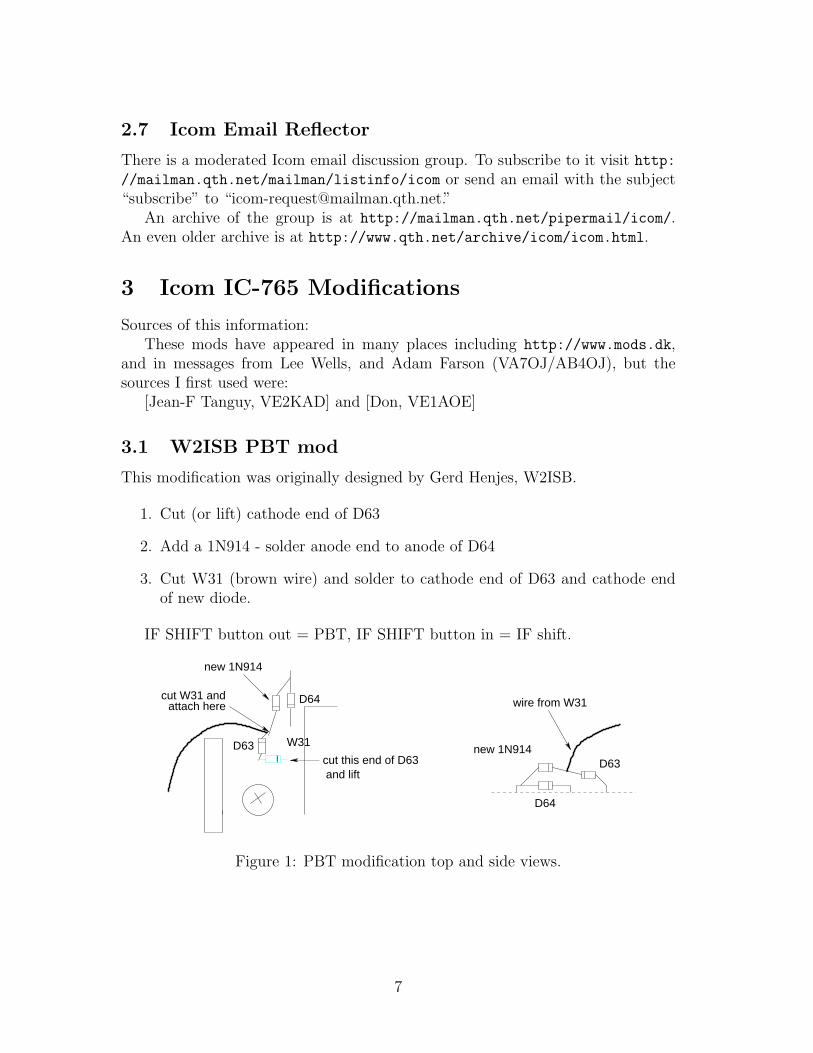
This modification was originally designed by Gerd Henjes, W2ISB.
1. Cut (or lift) cathode end of D63
2. Add a 1N914 - solder anode end to anode of D64
3. Cut W31 (brown wire) and solder to cathode end of D63 and cathode endof new diode.
IF SHIFT button out = PBT, IF SHIFT button in = IF shift.
D64
D63new 1N914
wire from W31
W31
D64
D63cut this end of D63 and lift
attach herecut W31 and
new 1N914
Figure 1: PBT modification top and side views.
7
3.2 Modification for improved T/R Switching
(prevents damage to D45, D46, D47, & D15 on RF Board.)Parts Needed: 47K 1/8 watt resistor 150K 1/8 watt resistor 1SS53 diode Insu-
lation for the resistor lead
1. Remove bottom cover
2. Remove screws from Main Unit and lift board
3. Remove R10 (39K) and R11 (39K) near IC-2
4. Install one end of new R11 (150K) to foil trace which connects to C13.Insulate remaining lead of R11 and solder it to Pin 3 of IC-2
5. Install new R10 (47K)
6. Solder D159 (1SS53) between Pins 3 and 13 of IC-2. Cathode side of diode(striped end) goes to Pin 3
7. Modification is complete. No adjustment is necessary. Reinstall the Mainunit and Bottom cover.
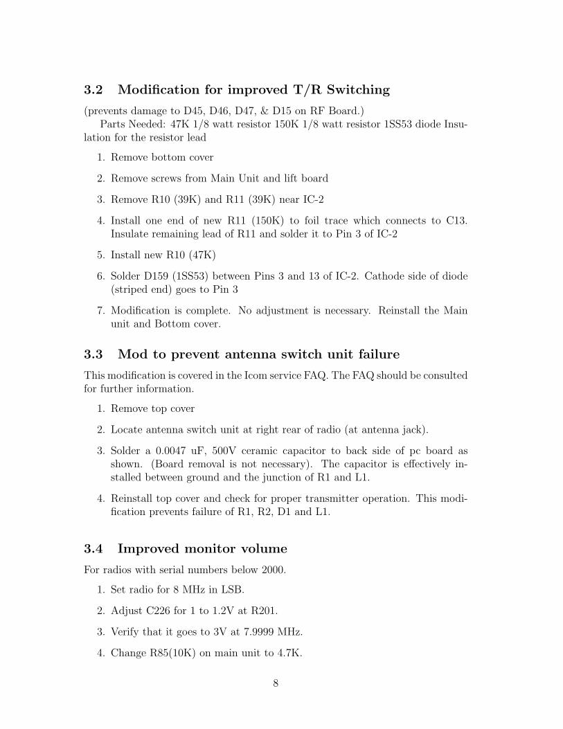
3.3 Mod to prevent antenna switch unit failure
This modification is covered in the Icom service FAQ. The FAQ should be consultedfor further information.
1. Remove top cover
2. Locate antenna switch unit at right rear of radio (at antenna jack).
3. Solder a 0.0047 uF, 500V ceramic capacitor to back side of pc board asshown. (Board removal is not necessary). The capacitor is effectively in-stalled between ground and the junction of R1 and L1.
4. Reinstall top cover and check for proper transmitter operation. This modi-fication prevents failure of R1, R2, D1 and L1.
3.4 Improved monitor volume
For radios with serial numbers below 2000.
1. Set radio for 8 MHz in LSB.
2. Adjust C226 for 1 to 1.2V at R201.
3. Verify that it goes to 3V at 7.9999 MHz.
4. Change R85(10K) on main unit to 4.7K.
8

.0047
rear of radio
Figure 2: Rear of antenna switch circuit board.
3.5 Extended TX Mod
1. Remove top and bottom covers
2. From the bottom of the radio locate the matrix board which is next to thefront panel.
3. Find diodes D50, D51, D52, D53, D54 and D55.
4. Cut one leg of D53
5. Assemble the radio and stay legal!
In addition, if you wish to use the antenna tuner, the following mod is required[From: Rick Robinson, K8DXN]:
1. Remove top cover.
2. Locate tuner control PCB. It is in the rear of the rig from the marker switchboard.
3. Locate plug going to J103.
4. Find grey wire going to Pin 8 on J103 — named “TUNM” on circuit.
5. Remove grey wire — that all, done deal.
3.6 Better AM Audio
1. Replace AM rectifier diode with schottky for better audio.
3.7 QRP mod
With this circuit connected to the radio, the power output is adjustable between0 and 100W. For best results, leave the RF power control at maximum and adjustfor desired power using R2.
9

Shielded cable
to ALC
jack
-
+
9 Voltalkalinebattery
47K
20K
S1
R1 R2
Figure 3: QRP adaptor for IC-765
S1 is used to turn off circuit when radio is not in use or QRP operation is notdesired.
Radio Model: R1 value R2 value
IC-761, 765 47K 20KIC-720(A), 735, 740, 745, 751(A), 275A/H 2M 1MIC-725, 726, 728, 729, 736, 737(A) 220K 100K
06/01/94 CJRFor the IC-820H use the values for the IC-761, 765. The IC-781, IC-765 and
the IC-820H all have the same ALC characteristics:
Control voltage: -4 to 0 voltsInput impedance: More than 10 K ohms
3.8 Selectable SSB Filters
This mod was on my ’765 when I purchased it. I don’t think it’s the best way todo it, but it works!
This unit has different SSB filters than a stock IC-765. An FL-70 (2.8 kHz)is used in place of the FL-30 (2.3 kHz) as the standard SSB filter. In addition,an FL-80 (2.4 kHz is selectable via the “250 Hz” button on the front panel. TheFL-80 is installed in the space allocated to the optional FL-101 250 Hz CW filter.
Filter -6 dB -60 dB
FL-30 2.3 kHz 4.14 kHzFL-70 2.8 kHzFL-80 2.4 kHz 3.84 kHz
10

This modification is illustrated in figures 5 through 6.
R312
R322
b
d
brown
red
J13
FLC
FLS
MatrixUnit
Figure 4: The Circuit Prior to Modification
FLC
FLS
cut
cut
W163 (8V)
bR312
R322
FL70
FL80
(lift R322 d end
J13 Matrix Unit
250 Hz
brown
red
OEG SRU-S-109L 9V relay
Figure 5: Circuit After Modification
The following steps perform the modification:
1. Cut the red (FLS) and brown (FLC) wires from J13.
2. Ground the brown wire (FLC).
3. Connect the red wire (FLS) to one end of the relay coil. Connect the otherend of the relay coil to W163.
4. Cut W154.
5. Connect the end (“d”) of W154 nearest to the PCB edge, to the relay “com-mon”.
11

6. Connect the other end (R312) of W154 to the relay NC connection.
7. Lift the end of R322, farthest from the filter, and connect it to the relay NO.
FL-70
FL-32A
FL-80
J13brown
red
W15
5W
154
to R312
b
d
W163
R322
FLS (red)
Figure 6: Pictorial of the Filter Modification
3.9 Using the 250 Hz second IF CW filter in RTTY mode
[From: Dave KD6TO]This allows use of the 250 Hz second IF CW filter (FL-53A) in RTTY mode.
• Install the optional 250Hz filter according to the instructions (if not alreadyinstalled).
• Remove the covers to gain access to the Main Unit PCB.
• Take a 1SS133 diode or equivalent and solder the positive side to the positiveside of D42 (accessable at pin 15 of IC11) and the negative side to the negativeside of D39.
12

• Re-assemble and test.
The CW 250Hz pushbutton will now select the 250Hz filter in both CW andRTTY modes.
3.10 New Version of the N6MZ Sidetone Tracking Modi-fication
Michael Mraz, N6MZ, author of the May 1993 QST article titled “Add TrackingSidetone to Your Icom IC-765 Transceiver” has suggested a new way of doing themodification:
I’d recommend doing the tracking sidetone another way. This mod ismuch simpler and actually uses the 765’s monitor mixer to beat theTX carrier oscillator against the RX BFO. The downsides are that thesidetone volume will vary a little, in proportion to the output powersetting, and that you won’t hear the sidetone when you aren’t trans-mitting (i.e. you can’t do CW practice with the “VOX” button off).
This is what I did:
1. Remove Q16 on the Main board. This transistor cuts off the BFOduring CW transmit.
2. Remove R77 on the Main board. This resistor couples the CWsidetone oscillator to the audio T/R switching circuit.
Now when you transmit, you should hear the actual tone resultingfrom the receive BFO beating with the transmit carrier oscillator. Thevolume of the audio sidetone will vary with the setting of the RFPWR control (more power = louder sidetone). If (and it’s a big if)all the mixer oscillators are aligned perfectly, when you tune the radioto match the sidetone frequency to the frequency of the received signal,you will be exactly zero-beat. My rig is accurate to within 10 Hz or so.
If you plan to work on the 765, you really should buy a copy of theservice manual, it has all the two-color drawings that show the com-ponent locations on the boards. It also has the calibration procedureand theory of operation.
Floyd, K8AC, adds the following:
I installed the new mod and find that it works just as Mike describes.The variation in volume of the sidetone with the setting of the powercontrol is of no consequence, since the sidetone volume is controlledby the monitor gain control (you must have the monitor ON to hear
13

the sidetone). While I haven’t taken the time to measure the sidetonefrequency against the received signal pitch, my ear says it’s the sameor extremely close.
If you don’t already have a copy of the 765 service manual, you canget one from Icom. But — the manual they are currently selling isnot a multicolor original, but a black and white copy. However, it’s avery good copy, right down to the large fold out pages, and perfectlyreadable. Finding Q16 and R77 is certainly easier with the manual.If you plan to give this a try without the manual, you can find thetwo components just behind the shielded BFO enclosure on the mainboard. The BFO alignment information is found in the 765 InstructionManual on page 47.
4 Common Problems
4.1 Antenna Tuner “Hunts” or “Chatters”
For either of these techniques the transceiver should be connected to a proper 50 Ωdummy load. Since the IC-765 apparently senses reflected power when tuning, itmay be worthwhile to perform the final adjustments/checks with a “reasonable”power level, for example, 40 watts.
4.1.1 Empirical Technique
This is the fix most commonly presented.
The feedback circuit that controls the tuning motors becomes sensitive after afew months of aging. It requires a one time adjustment to correct.
1. Remove top cover and locate the antenna tuner board.
2. Locate R5 and R10 and set them to the center of their range.
3. Set radio as follows: Tuner on Frequency 14.100 MHz Mode RTTY
4. After transmit is engaged for 30 seconds,
5. Adjust each control (R5 and R10) so neither motor tunes while changingfrom SSB to RTTY and back to SSB.
Note: R5 (right) controls right motor and R10 (left) controls left motor.
6. Repeat this adjustment to verify proper operation and then check on allother bands.
7. Reinstall top cover and return to operation.
14
4.1.2 Alternate Technique
This is an alternate adjustment procedure that may be more satisfactory.
• Subject: The antenna tuner on some IC-765s “hunts” during transmit afterthe first tuning phase is complete. This may start after a few months of use.
• Information: The feedback circuit that controls the tuning motors may be-come sensitive after a few months of use.
1. Remove the top cover and locate the antenna tuner board.
2. Locate R5 and R10 and set them to the center of their range.
3. Set the following controls on the radio as indicated below:
Tuner — On Frequency — 7.1 MHz Mode — LSB
4. After transmit is engaged for 10 seconds (to allow the tuner circuits to tuneand stabilize), and while still transmitting,
(a) Verify V-ref at R4 is between 4.6 and 5.3 VDC.
(b) Adjust R5 for a voltage that is one half of what was measured in step5 ± 0.1 VDC measured at R2.
(c) Adjust R10 for a voltage that is one half of what was measured in step5 ± 0.1 VDC measured at R7.
5. Verify proper tuner operation on all bands.
6. Reinstall the covers and return the radio to operation.
4.2 Problems covered in the Icom service FAQ.
The Icom service FAQ is copyright so I’m only going to list the problems coveredin it. Refer to Icom
(http://www.icomamerica.com/) for their FAQ.
• Unit will not transmit or receive on all bands. Very low noise from speaker.Display and controls all seem to work properly.
• Dead spots in the bottom 250 kHz (or so) range of each band when radio iscold. Dead spots may eventually get smaller then disappear as radio warmsup.
• No RX/TX when unit is first turned on, but will return if VFO knob is spunor if power is cycled on and off a few times.
15
• No RX/TX or distorted RX/TX on one or more bands. Distorted SSBaudio sounds raspy and rough. Some bands may sound OK. Problem maybe temperature related.
• Frequency unstable in SSB modes.
• Drastic change in audio frequency response between USB and LSB, i.e. USBaudio has too much bass while LSB audio has too much treble. USB/LSBRX frequency response may be equalized, to a degree, by adjustment if thefront panel IF Shift control. TX frequency response remains poor.
• No or very low RX sensitivity.
• Distorted RX on strong signals. BC band RX sensitivity may be low ormarginal.
• Intermittent RX sensitivity. Problem seems mechanical. Banging on case orswitching between RX & TX may temporarily restore sensitivity.
• RX disappears when outer shield of coax is connected to the antenna. In-spection reveals 6 volt DC at the center conductor of the antenna jack.
• PTT does not operate. When the SEND switch is flipped, the green RXLED stays lit and unit does not go in the transmit mode. Problem may beintermittent.
• No TX output in all modes. Problem is traced to no output at J8 on the RFunit.
• Distorted/raspy-sounding TX in SSB modes. Average power is low, evenat higher mic gain levels. Turning on the speech processor seems to help alittle. CW, RTTY and FM seems normal.
• No or low output on all bands with high Icc. Inspection reveals burned D1,L1, L2, R1, and/or R2 on the ANT SW unit.
• The power clicks off or flutters on and off when the TX power output isincreased toward maximum. Inspection reveals that the internal power sup-ply is unable to handle the current. Unit runs fine when the internal powersupply is substituted with an external power supply.
• Tuner operates properly when a carrier is present, but drifts out of tune inSSB mode.
• Tuner “chatters” or makes a rattling sound while speaking into the micro-phone in SSB mode, mostly on upper bands.
16

• Tuner does not tune on any band. Inspection reveals that only one motor isturning.
• Intermittent display. S-meter may peg and RX/TX may disappear when theunit is in the failure mode.
• VFO tuning is erratic: Sometimes skips frequencies in a certain area of VFOknob travel. 10 Hz display digit “flutters” instead of changing incrementallywhen the VFO knob is turned slowly.
• Loud, high pitched squeal emanates from inside radio. May be intermittent.
• TX monitor gain seems low, even at maximum volume settings. Radio hasgood mic gain, and the transmitter works OK.
• A mechanical whine emanates from inside radio in TX only at certain powerlevels. Transmitter works OK.
• CI-V interface does not work. Unit will not communicate with computer.
4.3 VOX Oscillates
[From: John Bielefeld, K1JEB]I have come up with the reason why my IC-765 VOX oscillates. The 8V power
for the Mic Pre-amp comes from the Main Unit Board. But daisy chains throughto and from other boards. This causes some transients to be induced in the 8Vpower line. The line is also made of a small gauge wire. The resistance on thisline is high enough for these transients to be quite large enough to trip the VOX.Also if you listen to the transmitted signal via the internal monitor you can hearsome of the digital noise generated.
The solution is:
1. Remove the 8V power pin 7 from connector J302 AF VR UNIT.
2. Remove the 8V power pin 3 from connector J103 NB SW UNIT.
3. Connect The 8V power pin (which came from pin 7 from connector J302 AFVR UNIT) to pin 3 to connector J103 NB SW UNIT. You may have to cutsome tie wraps to do this. Just add some new tie wraps when you are done.
Ok, now the AF VR Unit has no 8V power. So we need to get this 8V powerfrom the spare 8V power, pin 5 of J15 on the MAIN UNIT. I found some extrapush in pins from an old VCR tape player. Add an extra push in crimp pin intopin 5 of the female connector for connector J15. Next run a wire (feeding throughthe tie wraps) to the AF VR UNIT. Find another push in crimp pin. Connect the
17
8V wire to this pin. Then push this pin into pin 7 of the male connector whichplugs into J304 on the AF VR UNIT.
One item I did but not necessary is to use a thicker gauge wire for the groundreturn between the AF VR unit pin 8 J302 and the ground pin on the MAIN UNITpin 1 J15.
I also ran the shielded audio cable from the mic pre-amp and the VOX inputalong the metal chassis and away from the noisy harness it was tie wrapped to.This helped some but not as much as the power cable change.
With this mod, I now have very, very clean audio from the mic pre-amp.I would highly recommend this mod. It took me 2 hours to do.
4.4 W8AEF’s Problems and Fixes
[From Paul M. Playford, W8AEF]I have received several emails regarding my experiences with my IC-765 so here
they are:First, my ’765 is s.n. 002313 purchase new about 1990.After a couple weeks in the operating position I sensed that something was
wrong — couldn’t make any contacts. Nobody would answer my calls on 20meters. Put the 303-401 back on line and no problems. After much checking Idetermined that FL30, the 9 MHz SSB filter had a very deep notch on one side ofwhat was supposed to be the flat top, along with a sharp spike on one side of thepass band.1
The net result was with my voice characteristics, the meters would wiggle butnothing came out on USB. Icom sent me a new filter but it had a deeper notchthan the original so I installed Fox Tango ssb replacement filters in both IFs andthe radio works great now.
I fell in love with it. Started to learn how to use some of the bells and whistlesand (I think) work stations the old Heath stuff couldn’t have. Then more troublesstarted.
1. Intermittent transmit — Cold solder joint on one end of the meter currentshunt.
2. Receiver dead — 2 filter switching diodes shorted in the receiver.
3. Receiver dead — RF transistor in the receiver went open.
1Adam, VA7OJ/AB4OJ comments: This is related to the whole sorry PBT patent-infringement tale. Earlier IC-765’s (S/N < 3000) had up to 6 dB of SSB IF passband ripple, dueto mis-termination of the IF filters. This was left behind when the circuit designers, workingunder a court deadline, hastily “yanked out” the IC-761 PBT circuitry. This ripple causes severeattenuation of highs in the recovered audio when PBT is cranked up. I understand that theproblem was corrected for S/N > 3000. Note that in any event, the circuit changes involved inthe PBT mod do not change the filter terminating impedances.
18
Checked with Icom and they sent me a copy of the factory update to themain unit to prevent future failure of these components. The update hasalready been installed in my radio and the diode is also installed correctly.
4. Intermittent transmit — Cold solder joint on receiver Q7 PTT transistor.
5. Radio dead — Open winding in T1 in the regulator unit. This is a smalltransformer that “kick starts” the power supply on turn on.
6. Computer interface not working. Replaced defective L4 in CT-17 Commu-nication Interface-V.
7. Frequency readout jumps while tuning. Icom’s fix for this is to replace theoptical encoder. It’s long out of warranty by now and I’m too cheap for thatso I just repositioned the circuit board inside the encoder until the frequencyreadout didn’t jump.
8. Frequency changing — this one I haven’t found yet. It is intermittent andsounds like the IF SHIFT is wandering. Doesn’t happen often and when itdoes I power down the radio and it goes away. I just know it’s another coldsolder joint but have not had any success locating it.
-5.0 volt supply is wandering.
The source of this -5.0 volt supply is IC7, located on the display unit. Re-moved the cover from IC7 and soldered three pins in it that had never beensoldered. Several months later the display started flickering between dimand bright. I found 2 pins in this module that the solder had cracked (thesewere my soldered connections) because the pins are stiff and when you installthe module on the display board the pins usually have to bend a little to fitthe holes in the display board. When the pins don’t/won’t bend the soldergives. Be very careful when positioning these pins inside IC7 because thealignment is critical.
I replaced the three plastic trimmer capacitors in the BFO circuits (C42, C45& C307) per paragraph 5 of the Most Common Service Questions for theIcom IC-765 I found on the ICOM web site. Symptom: Frequency unstablein SSB modes.
9. Replaced the three plastic trimmer capacitors in the Carrier Oscillators(C123, C125 & C128). Symptom: CW was transmitting about 2 KHz higherthan receive. Made it a little <grin> difficult to make contacts.
Further: paragraph 4 of the above mentioned Most Common Service Ques-tions suggest replacing C11, C20, C29 and C37 on the PLL unit. I did thisas a preemptive strike before they gave me problems.
I have made several modifications to my ’765 (in addition to the repairs).The tracking sidetone that appeared in the May 1993 issue of QST is a
19

must do. I had the variable bandwidth tuning from the March 1991 issueof QST installed but removed it when my frequency changing intermittentarose. I will be re-installing the W2ISB PBT modification (it will allowboth IF SHIFT and variable bandwidth) as the IF SHIFT is useless, butthe PBT works very well. I have also installed PIN diodes in the receiverfilter switching. This is what I call a preemptive strike — not sure if theyimproved the performance but a 50KW am station just went on the air about5 miles from my QTH.
**********************
March 18, 1998
10. No transmit, receive OK. Transmit seems to produce about a 50 watt oscil-lation even in SSB and CW (not keyed).
Replace defective IC1, Q21, Q15, D46, D47, D45, Q14, Q8, C181 and C179.I think C179 shorted out first, causing the antenna relay to stick in the re-ceive position even while transmitting. Screwing up the transmit impedance,caused the oscillation and blew the components. All defective componentson RF UNIT. I think it would be well to replace all .1 uF capacitors on thisboard.
**********************
Spring 2000
11. No transmit, receive OK. Replace defective Q14 on the RF unit. Replacingthis transistor is getting old. I checked the ratings on the device and it’soperation in this application is well within it’s ratings. Close inspectionof the circuit reveals a possible path from the base thru C170, D45, C174,D47, C179 and RL1 on the RF UNIT, R211, L203, L204, C215, RL210 onthe ANT SW UNIT, and on thru RL13 on the TUNER unit to the rearpanel ANT connector. This is a real stretch to believe that could be aproblem, but then I remembered that I have already replaced some of thesecomponents. So, just as a precaution I installed a pair of 1N4006 diodesin parallel, opposite polarity, across the antenna input terminals. Put theradio back on line and the first time I turned the antenna — WOW, whata racket! The loud buzz was only present while the antenna was turning.Pulled the antenna lead off the radio and measured 3–4 vac between theradio chassis and the coax. Checked the schematic on the T2X rotator andI see that the common between the two motor windings and one side of thebrake solenoid are connected to the frame of the rotator. This point is alsoconnected to the chassis of the rotator control box via the control cable. If Ihad a poor a.c. ground at the top of the tower (it’s a crank up so I do) it isconceivable that while power was being applied to the motor and brake theground potential at the top of the tower would actually float, due to IR losses
20

in the rotator control cable. This is what I found to be true and this floatingground potential is what is coming back down the coax inner conductor andblowing components in the RF UNIT. I plugged the controller into a 3 pinto 2 pin ac adapter (that lifts the ground) and the buzz went away. I havesince corrected my grounding problem and it has been almost a year withno further failures in the rf unit. So, to those of us that lose components inthe rf unit — check your ground between your rotator and radio.
12. After modifying my Henry 2K-3 for QSK I observed that each element wasshortened during QSK operation. This originates in the 765 during fullbreak in and was cured by adding a .047 uF ceramic capacitor across thenormally closed contacts of the FULL BK-IN switch. This allows the VOXdelay circuit to complete the element. I found the same modification in TheFrankford Radio Club Newsletter — August, 1991 except they used a .022uF Mylar Capacitor. I should read my notes and then I would not have tore-invent the wheel.
Now that it has been almost a year since the last failure I have more time tooperate and reflect on why I have kept this radio. I am a DXer and contester andI feel this is the best radio available for this type of operating. I am particularlypleased that I have been able to keep my electronic trouble shooting skills sharpso I can repair my own equipment because, had I not found my own groundingproblems, I would still be blowing components regardless of the radio I was using.
de Paul– Some days you are the QSO, some days you are the QRMW8AEF -*- ZF2TA (1992) -*- FO0PLA (1997) -*- 8Q7AA (1998) -*- XZ0A
(2000)
4.5 Carrier Oscillator Trimmer Adjustment Corrections
[From: Mahlon Haunschild, K4OQ]RTTY Shift Frequency adjustment (appears on page 6-10 of the IC-765 service
manual):All frequency measurements taken from the top of R484.
21

“WAS”
Adj. Conditions Adjustment / Measurement
STEP 1:Freq. display: 14.10000 MHz Adjust C123 for 9.01145 MHzRTTY modeS2: 850 HzS3: NORMALTransmitting
STEP 2:S2: 170 Hz Adjust C125 for 9.01077 MHz
STEP 3:S3: REVERSE Adjust C128 for 9.0106 MHz
STEP 4:FM MODE Adjust L10 for 9.0100 MHz
“IS”
Adj. Conditions Adjustment / Measurement
STEP 1:Freq. display: 14.10000 MHz Adjust C123 for 9.01145 MHzRTTY modeS2: 170 HzS3: REVERSETransmitting
STEP 2:S2: 850 Hz Adjust C125 for 9.01077 MHz
STEP 3:S3: NORMAL Adjust C128 for 9.0106 MHz
STEP 4:FM MODE Adjust L10 for 9.0100 MHz
4.6 Icom 765 PLL Trimmer Repair — A Case History
[Courtesy: Rich, KA8OKH, Updated 11-10-01]See Rich’s web page, (http://home1.gte.net/web22jfw/), for his original
article.
22

I have had my Icom IC-765 HF transceiver for close to 7 years now. It haslogged many (perhaps hundreds) of hours of use. This past spring, however, itbegan to develop some quirks. One day while it was receiving on 30 meters duringa particularly busy contest weekend, I started noticing contest activity showing upon the band. The callsigns were recognized as leaders in the sport of contesting,and I found it odd that they would be active on this traditionally non-contest band.Another oddity — the signals were weak — weaker than I would expect from thesehigh power stations. No matter. . . the contest ended that Sunday evening andthings appeared to return to normal. A few weeks later, while operating on 40meters CW, the receiver suddenly drifted 500 Hz up over the course of 5 secondsor so, and stayed there. A couple of days after that, everything received below 10MHz would become garbled and unintelligible after 30–40 minutes of warmup.
At this point I decided that my trusty 765 was in need of some TLC. A few yearsago I had printed out and read the 765 troubleshooting notes on the Icom website (http://www.icomamerica.com/support/troubleshooting/ic-765.html),and I recalled something about raspy audio occurring after warmup, and that itsometimes affected certain frequency ranges. Sure enough, there it was — thedreaded plastic trimmer problem. Being a technician by trade, and not wantingto sacrifice my radio to the shipping gods for who knows how long, I decidedto attack the problem myself. Here I’ll describe for you how I got everythingback into shape for just a few dollars and a few hours of time. The repair is notdifficult. I feel that anyone with proper soldering technique and a decent digitalvoltmeter can do it. But if you feel squeamish about it, contact Icom Tech Support(http://www.icomamerica.com), and they will do the proper repairs for you.
What Happened?
What happens is this — the plastic trimmer capacitors in the PLL (phase lockloop) section of the radio are enclosed in a shielded can. This can also containsseveral coils that are covered with a wax to prevent (I presume) vibration. Also inthe 765, the PLL board is located directly below the internal power supply. Nowyou would think that the heat would radiate up and away from the PLL unit, butenough heat reaches the board to slowly, over years, cause the wax to flow downinto the trimmer caps. It then seems to eat away at the plastic dielectric of thetrimmers, causing the HPL lock voltage(s) to drift out of acceptable range, whichin turn causes all sorts of nasty things to occur. The raspy audio might just affecta certain range of frequencies, or several ranges, or all. In my case, it just affectedeverything below 10 MHz.
How do I Fix it?
Only one way — remove the plastic trimmers from the PLL board, and installceramic replacement units. We’ll go step by step, removing that nasty wax sub-stance (or most of it anyway), and re-align the vco’s according to the service
23

manual. While we’re in there, we’ll check out a few other things that may needattention. Time’s wasting, so let’s get started!
What You’ll Need
• Soldering iron — 15–25 watt
• Solder wick — to remove solder from traces and shield cans
• Soldering gun — here we want something on the order of 100 watt
• 60/40 rosin core solder (I use Kester Rosin Core 44)
• #1 and #2 phillips screwdrivers
• Small pair of “nippy” cutters (wire cutters). Smaller the better
• Small “jewelers” type screwdrivers, preferably plastic handles, or similar ad-justment tool
• Digital voltmeter
Of course you’ll also need the replacement trimmer capacitors. The capacitorswe’ll be replacing are designated C11, C20, C29, and C37. C11 and C20 are 10pF(picofarad), while C29 and C37 are 7pF. Now. . . here’s where I begin to deviatefrom the book a bit. First, let me say without equivocation — I have nothingagainst Icom service, or ordering replacement parts from them. However, in thissituation I had the parts in hand to do this repair, and they work fine. But — ifyou feel that you should get these parts from Icom, by all means do so. Here arethe Icom part numbers to ask for —
Icom part#
• 4610001130 — trimmers C11 & C20 (order two)
• 4610001000 — trimmers C29 & C37 (order two)
Now, having said that, you can also get suitable replacements from Digikey(www.digikey.com). They have to have leads spaced 4.5 mm apart, be ceramic,and of course be the proper capacitance. I found these Sprague GKG series ceramicunits (http://www.spraguegoodman.com/305/305p4.html) to be more than ad-equate —
Digikey part#
• SG1029-ND — 3.5–10pF ceramic (white — Sprague part# GKG10024)
I used this 10pF unit for all 4 caps. Why? Well, C11 and C20 were 10pFanyway, but Icom recommends in their service notes that C29 be changed from7pF to 12pF for ease of adjustment. C37 is(was) 7pF as well, so I figured why nottry a 10 there as well? No worries — the 10pF works just fine for all 4 replacements.
24

Let’s Start
Begin by laying your 765 on a CLEAN surface — a clean towel to keep fromscratching your radio. So as not to cause any confusion here, throughout thisrepair, keep the front of the radio facing you. Remove the little door that coversthe adjustments under the top cover, and set it aside. Remove the screws thathold down the top cover. Remove the top cover by gently lifting from the rear,then pulling back. Detach the internal speaker lead, noting the direction of theplug, and set the cover and screws aside. Now turn the radio over, and remove thebottom cover, and set it and the screws aside. Now flip the radio face up again.Ok, see that big black thing on the left side with cooling fins? That’s your 765’spower supply. Our bad caps are below it, so we have to get the power supply outof our way. It’s held in by 4 screws — 2 of them go through the left side of thechassis, the other 2 go down on the right side of the power supply into two littlechassis tabs. Remove these screws and unplug the two white interconnect cablesgoing to the supply. Lift the power supply out, taking care to not damage thecooling fins, and set it and the 4 screws aside.
Now what you see on the left side of the radio is the PLL unit. It can berecognized by a few shield cans, one with 4 access holes in the top. We’ll removethis board next. First, notice that there are a few cables that need to be discon-nected. There is one grey coax that cannot be disconnected at the PLL board.It runs under the chassis to the RF unit. Turn the radio upside down. The RFunit is on the right side, under a shield cover. Remove all the screws holding theshield cover down and remove it. Notice the grey coax in front of the RF boardthat goes through a grounding clamp — this is the coax we need to disconnect.Remove the screw holding the grounding clamp. Trace the coax over to the RFboard, and unplug it from the board. Pull the coax back through to the top ofthe radio. Turn the radio right side up again. Now remove the screws holding thePLL board down, and remove the board. Set the radio aside for now.
With the PLL board in front of you, again take note of the shield can withthe 4 adjustment holes. Our 4 bad caps are under that cover (you can see themthrough the access holes), so this cover has to be removed. Using a soldering gun,apply heat to the corners of the shield cover, and use wick to remove the solderfrom these areas. It sometimes helps to gently pry on the corners with a smallscrewdriver while heating. Take your time, and don’t apply too much force onanything.
Now flip the board over, and remove the lower shield from the area underneaththe shield can. Using a solder gun, apply just enough heat to free each tab on thelower shield. Locate the mounting holes for the 4 caps, and desolder them usinga 15–25 watt iron and solder wick. Now working from the top of the board, pullthe old trimmers out (if they didn’t fall out already). See all that tan gummystuff inside the can? That’s the wax that has caused our grief. Using a jewelersscrewdriver, gently dig out the wax from the vicinity of the trimmer mounting
25
holes. If there are signs of wax that may later migrate down into the area of thecaps later on, go ahead and gently remove it, taking care to not distort any coilsor break any other components. If the wax is fairly solid, it sometimes helps toapply heat from a blowdryer while scraping.
After the areas have been cleaned, install the new trimmers in their properpositions and solder them in. Be sure to clip the leads flush with the boardunderneath so they don’t touch the lower shield. At this point inspect all thetraces underneath the shield can for possible cold joints and touch-up with a littlesolder as necessary. Icom recommends doing this before re-attaching the lowershield, so I suspect they have seen problems with solder joints here — so it’s bestto give it a good look-over.
Reassembly
Re-attach the lower shield to the underside of the PLL unit. Re-attach the topshield can cover (the one with 4 holes), taking care to orient the cover so you cansee the trimmers through the adjustment holes, and solder the corners. Mount thePLL unit back into the chassis, taking care to not pinch any connecting cables.Re-attach all connectors. Re-route the grey coax to the RF unit, attaching thegrounding clamp. Attach the coax to the jack on the RF unit. Replace RF unitshield cover.
With the radio right side up, connect the plugs to the power supply, but donot put the supply back in the radio yet. You can lean it up against the left sideof the chassis for now. Plug the AC cord in, and attach some sort of antenna(dipole, piece of wire, whatever). Turn the radio on. Don’t worry if you can’treceive anything. You probably won’t right now, as the new trimmers need to beadjusted.
Alignment
Remember — radio is right side up, facing you.Now the Icom service manual says to use an oscilloscope to make these ad-
justments, but I obtained excellent results with a good digital voltmeter (DVM).Attach the dvm ground lead to the chassis. Attach the positive lead to resistor R6on the PLL board. R6 can be found immediately to the left of the 4-holed shieldcan that we worked on — it’s marked on the board. Next we’ll make a series ofadjustments to our new trimmers, working from the front trimmer (C11) to theback (C37).
• Set frequency to display 7.99999 MHz, and select LSB mode. Adjust C11(the front adjustment hole) for a reading of 6.5 volts DC on the dvm.
• Set frequency to display 14.99999 MHz, LSB mode. Adjust C20 (2nd fromfront) for a reading of 6.5 volts DC on the dvm.
26

• Set frequency to display 21.99999 MHz, LSB mode. Adjust C29 (3rd holeback) for a reading of 6.5 volts DC on the dvm.
• Set frequency to display 29.99999 MHz, LSB mode. Adjust C37 (rear) for areading of 6.5 volts DC on the dvm.
• Now check the voltage at the following 4 frequencies to ensure that it is morethan 2 volts DC.
0.03000 LSB
8.00000 LSB
15.00000 LSB
22.00000 LSB
Together. . . Again
Re-install the power supply, taking care to not pinch any of the leads or damagethe heat sink fins. Now would also be a good time to inspect the big white powersupply plug for any signs of damage. Several 765 owners have had trouble withthis plug, again due to heat. The plug will turn brownish in color, and becomebrittle. Contact Icom Service for a proper replacement.
Attach the top and bottom covers, speaker plug, and top access door. Enjoy!Rich, KA8OKHThe author assumes no responsibility whatsoever for damages — absolutely
nothing is expressed or implied here. Perform this repair at your own risk. If youfeel this repair is beyond your ability, please contact Icom Service for repair/parts.
5 Operating Hints
5.1 AM Operating Suggestions
[From: Art Pightling, K3XF]I have operated AM with many SSB/CW oriented multi-mode rigs as follows:
1. Set your microphone gain (in SSB) by speaking normally into your micro-phone as you observe alc action. (RF output is at max for this.) Start atzero mic gain and advance until you begin to see alc activity. Decrease micgain just below this point so no alc activity is noted. Leave the mic gain atthis point for the duration of your AM operation.
2. Turn on your compressor. Check to see that you do not exceed the alcrange as you speak normally into the microphone. If you do, adjust yourcompressor so you don’t.
27

3. Determine what your full output power is on CW.
4. Set your output with the RF power adjust to 20–25% of that amount. Leaveit there for the duration of your AM operation.
5. Switch to AM. You should have very close to 95% AM modulation with thisprocess and sound pretty good. Do some on the air audio checks to assureyou are OK.
6. Turn on your amp and you will have a good signal without overdriving orsplatter. Do some more on the air checks with the high power level. AMfolks love this part — if you get disparaging remarks about the origin of yourrig, tell them you are using this configuration until you finish your pair of4-400s modulating a pair of 4-400s excited by your ’765 . . .
5.1.1 Comments on the IC-765 on AM
Adam Farson, VA7OJ/AB4OJ had this to say about using the IC-765 for AM:
The IC-765 is not really characterised for AM transmission. It fakes outAM by injecting an exalted carrier at the virtual-carrier point. In AMmode, the radio transmits only one sideband, whilst the newer DSPradios (IC-756, IC-756Pro/Pro II) generate a mathematically-perfectDSP AM (A3E) signal with the correct carrier/sideband amplituderelationships. I would not endorse the IC-765 as a high-end AM rig.The receiver is OK for SWL’ing, but lacks a synchronous demodulator.
5.2 PSK31: CW Receive and LSB Transmit
[From: George T. Baker, W5YR]I have been asked by several fellow warblers to document the exact setup I
use with my Icom IC-765 that allows me to receive PSK31 signals using the 500Hz and 250 Hz filters. In the 765, and in many other rigs of its vintage, filterselection is tied to mode selection, and the narrow filters are available only in theCW Narrow or RTTY Narrow modes. Additionally the 765 allows 250 Hz filteruse only in CW Narrow mode in which the 500 Hz filter is already engaged.
Peter (G3PLX) has made a strong case that narrow filters prior to the filteringoperations within PSK31 have little beneficial effect on improving print in theface of strong adjacent signals. I agree completely and defend my use of narrowfilters only on the basis of (1) they keep me from hearing a lot of QRM/QRN;(2) they possibly improve copy somewhat by keeping strong nearby stations fromcontrolling the receiver AGC; and (3) I am accustomed to the sound of the receiverwhile receiving CW, my other favorite mode, and find it more natural to tune toa 700 Hz signal than to a 1000 Hz signal.
28

I had hoped to keep this note somewhat brief with only the procedural stepsbeing described, but the length of the end product confirms that I failed.
A lot can be said on the theory of operation of the 765 which requires thatcertain of these steps be performed, but that is the subject of perhaps anothernote if enough folks are interested.
Setup for the PSK31 Program
1. Sample rate: whatever works for your system; 11025.0 works fine for meand provides a transmitted tone that is within much less than 0.1 Hertz ofwhatever PSK31 frequencies are selected.
2. Center Frequency: 700
3. Callsign
4. Inverted QPSK: checked, as we will be receiving on a lower-sideband modewhen we select CW for receiving
5. PTT control: as appropriate
6. Narrow filter: personal preference — I like to use it so mine is checked.
7. On the main window, check AFC and NET. Tx and Rx frequencies will bothbe 700 Hz initially but will change with AFC and NET action.
Setup for the IC-765
1. Select VFO operation
2. Select SPLIT mode to receive on VFO-A and transmit on VFO-B
3. Set VFO-A to CW Narrow mode
4. Using VFO-A, tune in a PSK signal to a tone of 700 Hz to be centered inthe waterfall display, much as you would tune a CW signal to that beatnote.Since the 765 tunes only in 10 Hz steps, you must allow PSK31 to do thefinal tuning within a 10 Hz range with the AFC function. Give the programa few seconds to AFC the signal to the center of the waterfall — note thenew Rx Frequency and its offset from 700 Hz.
(I find it convenient to tune the 765 dial such that the offset is less than 10Hz — more on this later: NOTE A)
5. With the PSK signal tuned in and centered in the waterfall, press ‘A=B’and hold it until the function is completed (two beeps sound) in usual 765fashion.
29

6. Press ‘VFO A/B’ to transfer control to VFO-B
7. Change the mode to LSB
8. KEY STEP: *increase* the dial reading by 0.7 (700 Hz). Example: you tunein the PSK31 station with VFO-A with the dial reading 14.071.53. Whenyou have switched to LSB on VFO-B, change the dial to read 14.072.23,which is 700 Hz higher.
(This is the crucial step which causes the 765 to transmit your PSK31 signalon very nearly the same frequency as you are receiving — more on this later:NOTE B)
9. Return control to VFO-A with the ‘VFO A/B’ button
10. Continue, receiving in CW Narrow mode with VFO-A and transmitting inLSB mode with VFO-B.
WHEN YOU TRANSMIT, USING VFO-B IN LSB MODE, YOUR ACTUALTRANSMITTED FREQUENCY WILL DIFFER SLIGHTLY (10 HZ OR LESS)FROM THAT OF YOUR CONTACT SINCE YOU CAN ONLY SET FRE-QUENCY IN THE 765 TO THE NEAREST 10 HZ. DON’T WORRY — ONAVERAGE YOU WILL BE OFF NO MORE THAN 5 HZ AND AFC AT THEOTHER END WILL SHORTLY HAVE YOU TUNED IN ON THE NOSE! THENET AND AFC CAPABILITIES AT EACH END WILL KEEP THINGS TO-GETHER.
Now, all that sounds complicated and long and tedious — it does because Ialmost told you how to build a clock when you asked for the time. Operationally,it is much simpler:
1. Tune in the PSK31 station with VFO-A
2. A=B and change to VFO-B
3. VFO-B to LSB and 0.7 higher dial reading
4. Back to VFO-A and carry on
That is the brief procedure that you do each time you change to a differentfrequency/station, but in return for those few seconds of button-pushing and knob-twisting, you get 500 Hz and/or 250 Hz selectivity.
Now, for some fine print:
30

Note A
PSK31 can “grab” a signal anywhere in the waterfall, up to 250 Hz away fromcenter, and with a mouse click move it to the center and adjust the Rx Frequencyand Tx Frequency to match. That is good and convenient. But, there are twopossible “gotchas” here!
First, we have to be careful to ensure that our transmitted frequency (whichwill be the LSB dial frequency less 700 Hz ± the AFC-controlled offset from 700Hz) remains sufficiently within the transmitter LSB passband to output the powerwe desire. The problem here is that 700 Hz is down a bit on the SSB filter skirtand, on my rig, just barely puts out full power as compared with a 1000 Hz signalwhich is well within the filter passband and produces full power easily. Yourmileage may vary as not all filters are the same. I did find that lowering the TxFrequency to 600 Hz or below noticeably reduced the transmitter power output.In any event, since most folks seldom run over 50 watts output on PSK31 thissmall power reduction should not be a problem.
Second, the other side of this coin concerns the CW Narrow filters which areeffectively centered on 700 Hz. If we use a Rx Frequency very far removed from 700Hz, we run the risk of operating on or near the filter skirts with decreased outputand possibly some slight phase distortion. My tests show that if Rx Frequencyremains within about ± 100 Hz of 700 Hz, the received signal remains well withinthe 765’s 250 Hz filter passband.
In summary of this point, you can operate with a Rx Frequency from about 600Hz to about 800 Hz with no problem from the 765 receive filters. You can transmitat any reasonable frequency *above* 700 Hz and again no problem. But, if TxFrequency is much below 700 Hz your transmitted signal power will be decreased.
Note B
The procedure above specifies that 0.7 is to be added to the received signal fre-quency when adjusting VFO-B in LSB mode.
THIS IS THE CORRECT NUMBER *ONLY* IF THE 765 BFO FREQUEN-CIES ARE CORRECTLY ADJUSTED.
If your 765 has not been recently aligned, a simple test will enable you tocorrect for any mis-alignment and still use the procedure.
In Step 10 above when you have returned to VFO-A, verify that the PSK31signal is still centered in the waterfall and note the RX Frequency reading in thewindow. In particular, note the offset from 700 Hz. Now, press ‘VFO A/B’ toreturn to LSB mode. If your 765 is correctly aligned, you will be within a fewHertz of the same Rx Frequency and within a few seconds, the phase scope will becentered. Note the total frequency difference between Rx Frequency with VFO-Aand with VFO-B after the AFC has settled down. That is the total frequencydifference with which your signal will be received at the other end and is theamount that the other station’s AFC will adjust for your signal.
31

If the required frequency change is over 10 Hz, then your BFO frequencies areoff. However, this is easily compensated for without realignment of the 765. WithVFO-B simply adjust the dial reading slowly up or down in 10 Hz steps untilyou find the dial reading in LSB mode that gives the *smallest* Rx Frequencydifference between using VFO-A and VFO-B. That will also be the dial readingthat comes closest to centering the phase scope and gives you good print. Whenyou have the right value, the signal should sound exactly the same in either receivemode, except for the added noise, etc. in the LSB mode. Subtract that dial readingfrom the VFO-A dial reading, or vice versa, and that is the number that you addto the VFO-A dial reading in Step 8, instead of 0.7.
An example: VFO-A dial is 14.071.53. You find that you have to set VFO-Bdial to 14.072.24 instead of the 14.072.23 we used in the example in Step 8. Thedifference is 14.072.24 less 14.071.53 = 0.71. So, the frequency value for your radioto add to the VFO-A dial reading will be 0.71 instead of the ideal 0.7. It worksthe other way as well. Suppose that your dial reading is 14.072.22. Subtractingthis from 14.071.53 gives 0.69 for your number. In both cases, one of the BFOfrequencies is off by 10 Hz one way or the other.
This change from 0.7 makes no difference in system performance — you aremerely correcting for a small discrepancy in 765 alignment. However, if the cor-rection is more than a few tens of Hertz, you probably need to realign the BFOfrequencies.
With the proper dial increment value in place, you can switch between VFO-A and VFO-B and except for the few seconds it may take the AFC to make itscorrection, you should get perfect copy while receiving in either mode. Again, onaverage, you will almost always be within 5 Hz of correct, centered tuning andthat range will provide good print throughout.
Should your rig drift about, you might find that you need to change the actualfrequency value you use as the “adder” but mine has remained very constantat 0.7 since I last realigned it a few weeks ago. I should also mention that my765 stays on 24/7/365 as a precaution against drift and in connection with someother activities. In any event, each time you set up for another station, you willimmediately find out if your adder is correct, and if not what the correct oneshould be. Just use whatever value gives approximately the same Rx Frequencyvalues with CW Receive and LSB Receive.
As a final disclaimer, please note that most if not all micro-processor-controlledIcom rigs prior to the 765 change the dial frequency reading by a fixed amountwhen the mode is changed. I know that was true up through the 761. Obviously,the procedure given above would have to be altered to take that dial reading changeinto account. Since I do not have access to any other Icom rig, perhaps someoneelse can pioneer one of the earlier Icom’s for us.
I apologize for the length of this note, but I felt that more 765 owners wouldfeel confident to try this operating style if I provided a little more than just a bare-bones “do this and then do that” procedure. I find that the few seconds required
32

to set up for a new station are well invested in return for the capabilities providedby the narrow filters.
Please direct any questions to me privately unless you feel that others mightshare your concern and would be interested in the answers. I especially invite usersof other makes of rigs to see how this procedure, appropriately modified, workswith their systems.
5.3 CW Keyer Speed
The internal keyer can be varied between 5 and 11 wpm (slow setting) and 10 and48 wpm (fast) as shown in figure 7.
5
7.5
Slow
9
17
Fast
10
11 12
30
44
48
Figure 7: CW Keyer Speed
6 Microphones
6.1 Connection to an MC-60A Microphone
A Kenwood MC-60A may be used on an IC-765 if the existing cable is rewired ora new cable is made. The pinouts for the MC-60A and the IC-765 are shown inFigure 8.
Icom uses a single wire for Up/Down while Kenwood uses 2 wires. See Figure 9for the Icom scheme.
The wiring for a new cable is shown in Figure 10.I wasn’t pleased with the audio quality from this combination.
6.2 Using a computer headset
Rick Meilstrup, OZ5RM describes how to use a computer headset with an IC-765:
A cheap headset ($12-15), like the kind used with a computer, makesan excellent, light-weight replacement for a separate mike and speaker.In order to connect it to our IC-765 we have to make an adaptor. Iused an empty film canister. Two small sockets are fitted on the can’s
33

1
2
3 4 5
67
8
Up
Down
PTT
Tx Audio
8 VDC
Tx Audio Ground
Chassis Ground
Kenwood MC-60A Wiring
(blue)
(black)
(yellow)
(red)
(grey)
(shield)
(green)
Received Audio(orange)
(colours are those used in my oem MC-60A cable)
1
2
3 4 5
687
Tx Audio
8 VDC
Tx Audio Ground
Received Audio
PTTUp/Down
Squelch
PTT Ground
Icom IC-765 Microphone Wiring
Figure 8: Microphone connectors. (Chassis connector as viewed from outside).
Up/Down
470
Up
Down
Icom Up/Down Wiring
Figure 9: Icom Up/Down Wiring
34

MC-60A Icom
1 white 12 black 53 blue4 red5 orange 26 --7 shield 78 green 6
3470
(colours are those used in my cable)
Figure 10: MC-60A cable for use with Icom IC-765.
lid, and a suitable hole is made in the bottom of the canister. An Icom8 pin mike plug is fitted with a short length of shielded multicore cableand the other end of the cable is passed through the hole, then solderedto the two sockets, one for the mike, and one for the headphones. Inorder to have the sound appear in both sides of the ’phones I short-circuited the two stereo pins on this particular socket. There is noprovision for PTT. Instead, I use VOX and adjust various controls onthe 765. The audio quality is on par with my SM6 mike, so say myfriends.
On my own adapter I added another jack for a separate push button PTTswitch (from an old computer game). The microphone is connected to pins 1 and7, the headphones (series or parallel, depending on impedance) to pins 8 and 6,and PTT to pins 5 and 6. Inside the IC-765 pin 1 is connected, via 1820 ohms ofresistors, to +8V and this nicely powers the electret element.
7 Change Log
7.1 V1.00, 2002.01.2
• - initial release
7.2 V1.01, 2002.01.30
• - new high serial number
• - updated Icom email reflector info
35

• - updated antenna tuner adjustments
7.3 V1.02, 2002.09.10
• - KD6TO’s filter mod
• - new sidetone mod
• - html version no longer supported
36

References
[1] Exploring the synthesizer in a commercial mf/hf transceiver. In Paul DanzerN1II, editor, The ARRL Handbook for Radio Amateurs, chapter 14, pages14.49–14.52. The American Radio Relay League, Inc., 75th edition, 1998.
[2] Mark J. Wilson AA2Z. Icom IC-765 160- to 10-meter transceiver. QST, pages52–55, December 1990.
[3] Duane A. Calvin AC5AA. Icom IC-765 mods revisited. QST, September 1996.See Straw Dec 1995.
[4] Rich Guski KC2MK. Variable-bandwidth tuning for the Icom IC-765transceiver. In Hints & Kinks 13th Edition May 1992, pages 1–17–1–18.
[5] Rich Guski KC2MK. Variable bandwidth tuning for the Icom IC-765. QST,1991.
[6] Dean Straw N6BV. Modifying the Icom IC-765 for better sounding audio andagc. QST, pages 78–79, December 1995. See Technical Correspondence Sep1996.
[7] Michael A. Mraz N6MZ. Add tracking sidetone to your Icom IC-765transceiver. QST, pages 39–42, May 1993.
[8] Michael Cobuccio WA1EYP. The Icom IC-765. 73 Amateur Radio, pages 22,25,February 1990.
37