icl technical journal - fujitsu · le secteur informatique a connu une forte explosion du nombre de...
TRANSCRIPT

ICL TECHNICAL JOURNAL
V o lu m e 8 Is s u e 1 M a y 1992
Published byInternational Computers Limited atOxford University Press

TECHNICAL JOURNAL
The ICL Technical Journal is published twice a year by International Computers Limited at Oxford University Press.
EditorJ.M.M. PinkertonICL, Lovelace Road, Bracknell, Berks RG12 4SN
Editorial Board
J.M.M. Pinkerton (Editor) M.R. Miller (BT Laboratories)P.J. Cropper W. O’Riordan(Northern Telecom Europe) A. RowleyD.W. Davies FRS D. Overkleeft (Holland)G.E. Felton E.C.P. PortmanP. Galais (Retix, France) D. Thomelin (ICL France)M.D. Godfrey T. Uehara (Fujitsu)(Stanford University) B.C. Warboys (UniversityJ. Howlett of Manchester)M.H. Kay H.J. WinterbothamF.F. Land (BNR Europe Ltd)
All correspondence and papers to be considered for publication should be addressed to the Editor.The views expressed in the papers are those of the authors and do not necessarily represent ICL policy.1992 subscription rates: annual subscription £60 UK and Europe and $120 rest of world; single issues £36 UK and Europe and $72 rest of world. Orders with remittances should be sent to the Journals Subscriptions Department, Oxford University Press, Pinkhill House, Southfield Road, Eynsham, Oxford 0X8 1JJ.
This publication is copyright under the Berne Convention and the International Copyright Convention. All rights reserved. Apart from any copying under the UK Copyright Act 1956, part 1, section 7, whereby a single copy of an article may be supplied, under certain conditions, for the purposes of research or private study, by a library of a class prescribed by the UK Board of Trade Regulations (Statutory Instruments 1957, No. 868), no part of this publication may be reproduced, stored in a retrieval system or transmitted in any form or by any means without the prior permission of the copyright owners. Permission is, however, not required to copy abstracts of papers or articles on condition that a full reference to the source is shown. Multiple copying of the contents of the publication without permission is always illegal.© 1992 International Computers Limited. Registered office, ICL House, 1 High Street, Putney, London SW15 ISW. Registered in England 96056
Printed by H Charlesworth & Co Ltd, Huddersfield ISSN 0142-1557

TECHNICAL JOURNALVolume 8 Issue 1
C o n ten tsFrench Translations of Abstracts iiiGerman Translations of Abstracts viiiEditorial xiiiForeword 1
Defining CASE RequirementsP.J. Vyse 3
ICL’s ICASE ProductsE. Felton and E. Soutter 23
The Engineering DatabaseD. Clarke, K. Matthews and J. Pratt 39
CASE Data Integration: The Emerging International Standards A .K. Thompson 54
Building Maintainable Knowledge Based SystemsF. Coenen and T. Bench-Capon 67
The Architecture of an Open DictionaryM.H. Kay 85
The Use of a Persistent Language in the Implementation of a Process Support SystemR.M. Greenwood, M.R. Guy and D.J.K. Robinson 108
ALF: A Third Generation Environment for Systems Engineering D.E. Oldfield 131
MASP/DL: The ALF Language for Process ModellingP. Griffiths 139
The ALF User Interface Management System M. Anderson 147
A New Notation for Dataflow Specifications M. Stubbs 159
Book Review 173
Guidance to Authors 176
ICL Technical Journal May 1992 i

Resumes
Philip J. VyseICL CASE Product Centre, Reading, Berks, Royaume-Uni Definition des besoins en matiere de genie logiciel assiste par ordinateur
Le secteur informatique a connu une forte explosion du nombre de produits de genie logiciel assiste par ordinateur (CASE) commercialises par les vendeurs d’outils, chacun faisant des proclamations impressionnantes pour ses produits. II est difficile pour les utilisateurs potentiels de ces outils de faire face a cette publicite tapageuse. Les preuves de toutes ces proclamations sont rarement quantifies. Les entreprises sont confrontees a des investissements a hauts risques, qui doivent neanmoins etre pris en consideration puisque le nombre de leurs developpements en retard refuse de diminuer. Cet article positionne les outils CASE du commerce dans leur contexte organisationnel. II examine la technologie CASE pour exposer son architecture et propose 1’evaluation de la maturite actuelle en la matiere avant l’introduction de changements radicaux. II decrit ensuite une methode d’identification des besoins qui met en rapport le genie logiciel assiste par ordinateur avec l’usage actuel des systemes d’information et la strategic au sein de l’organisation. Cette methode peut etre documentee pour fournir un enonce concis des exigences, qui peut etre utilise pour reduire la liste des fournisseurs potentiels et determiner si leur solution est appropriee.
Eric Felton et Eric SoutterICL CASE Product Center, Reading, Royaume-UniLes produits ICASE de ICL
L’industrie informatique et la communaute des informaticiens ont constate que deux des problemes fondamentaux associes aux methodes conventionnelles de developpe- ment d’applications informatiques sont le nombre d’applications en retard de de- veloppement et le cout de la maintenance des applications existantes.
Cet article decrit la maniere dont ICL a aborde ces problemes avec l’environnement integre de genie logiciel assiste par ordinateur (ICASE) QuickBuild.
David Clarke, Keith Matthews, John PrattICL Secure Systems, Winnersh, Berks, Royaume-UniLa base de donnees d'ingenierie
Appliquee au developpement de logiciel, l’expression “base de donnees d’ingenierie” peut ne pas etre universellement familiere. Dans cet article, elle designe la gestion de l’ensemble des informations formelles relatives a la conception d’un systeme. Elle est congu comme si elle devait prendre en compte les disciplines classiquement associees au bureau de dessin d’une entreprise de genie mecanique, c’est-a-dire plus specifi-
ICL Technical Journal May 1992 iii

quement, celles qui concernent l’enregistrement, l’autorisation et la mise en oeuvre de toutes les modifications d’une conception existante, qu’elles soient relatives aux materiaux, aux composants ou aux methodes de fabrication ou d’assemblage.
Les concepts et caracteristiques d’une “base de donnees d’ingenierie” sont etudies de la perspective de i’utilisateur, en classant les pratiques actuelles des utilisateurs, les fonctions necessaires pour les assister et les caracteristiques essentielles d’une base de donnees supportant de telles fonctionnalites. L’article decrit un systeme experimental actuellement en cours devaluation.
A.K. ThompsonThe Institute of Software Engineering, 30 Island Street, Belfast, Royaume-Uni Integration des donnees en genie logiciei assiste par ordinateur: l 'emergence des normes internationales
Cet article compare les trois principaux candidats en matiere de norme internationale dans le domaine de l’integration des donnees des outils de genie logiciei assiste par ordinateur (CASE).
II identifie les principaux composants requis par une telle norme et les utilise pour analyser la norme IRDS (Information Resource Dictionary System) de 1’ISO (International Standards Organisation), la norme PCTE (Portable Common Tool Environment) de 1’ECMA (European Computer Manufacturers Association) et la norme CDIF (Case Data Interchange Format) de l’EIA (US Electronic Industries Association).
L’article conclut que, bien que les trois normes en presence se recoupent a bien des egards, il existe egalement des possibility importantes de collaboration, il commente la situation actuelle et les possibilites futures en ce sens.
Frans Coenen et Trevor Bench-CaponUniversite de Liverpool, Departement d’InformatiqueCreation de systemes a base de connaissanc.es avec possibilites de maintenance
Pour que l’utilisation des systemes a base de connaissances de 5eme generation se repande dans les annees 90, dans la pratique, il convient de respecter de solides principes de genie logiciei. L’un des aspects importants de ce probleme est la “mainte- nabilite”. Cet article decrit quelques-uns des resultats du projet MAKE (Maintenance Assistance for Knowledge Engineers), qui est proche de conclusion. Le but du projet est d’etudier le role important de la maintenance dans les systemes a base de connaissances et, en particulier, celles fondees sur des sources ecrites, dont les exem- ples les plus representatif sont fournis par les systemes legaux et quasi legaux. Ces systemes peuvent etre envisages a differents niveaux: niveau source, niveau representation des connaissances et niveau representation executable cible. On suggere que la solution du probleme de la maintenance de tels systemes repose sur la maintenance de la representation des connaissances intermediates plutot que sur la modification du code utilise dans la representation executable cible. La maintenance est done plus un probleme de representation des connaissances que de programmation. La maintenance peut considerablement etre amelioree par l’utilisation d’un environnement de developpement et d’une methodologie adaptes et appuyes par un ensemble d’outils
iv ICL Technical Journal May 1992

de maintenance qui se concentre sur cette representation intermediate et sa relation avec les sources pour augmenter les capacite de comprehension et, par consequent, d’adaptation.
Cet article decrit un environnement de ce type, MADE (Make Authoring and Development Environment). II a ete developpe dans le cadre du projet MAKE et est con?u pour encourager la production de systemes dont la maintenance peut etre effectuee a travers d’une representation intermediate. MADE est support par une serie d’outils de maintenance visant a une meilleure comprehension de la representation intermediate et destines a la realisation de diverses taches de validation, verification et administration. Les outils de maintenance de MAKE sont egalement decrits.
L’environnement, la methodologie et les outils de MADE ont ete utilises pour creer un systeme a base de connaissances pilote pour la British Coal’s Insurance and Pensions Division. II est actuellement toujours en developpement, mais quelques resultats encourageant indiquent que de solides fondations ont ete etablie pour la realisation de travaux ulterieurs.
Michael H. KayICL Fellow, Reading, Royaume-Uni L’architecture d ’un dictionnaire ouvert
Cet article explique comment le role traditionnel du dictionnaire de donnees peut etre renforce et transport dans un univers de systemes ouverts, en depit de l’absence d’accord sur des normes internationales. La souplesse et l’adaptabilite sont des exigences essentielles; l’article montre comment il a ete possible de respecter ces exigences en adoptant une architecture orientee objet.
R. Mark Greenwood, Michael R. Guy, D. John K. Robinson Process Support Environments, Technical Strategy, ICL Kidsgrove, Royaume-Uni L’utilisation d ’un langage persistant dans la mise en oeuvre d ’un systeme de support de processus
Cet article decrit comment un langage persistant, PS-algol, a ete exp lo it pour mettre en oeuvre un systeme de support de processus. II explique les concepts de persistance, ainsi que d’autres proprietes de PS-algol, qui lui apportent une valeur ajoutee. Parmi ceux-ci, on peut citer les procedures de premiere classe, la capacite d’un programme PS-algol de se modifier lui-meme au moyen du compilateur recursif et le type de pointeur universel qui permet une edition de liens souple.
Le systeme de support de processus PSS execute des modeles de processus ecrits en langage PML. La caracteristique centrale de PML est le role. II s’agit d’un objet qui communique avec d’autres roles par l’intermediaire d’interactions ou messages. Le composant central de PSS est un moteur de controle de processus qui supporte la compilation et l’execution de programmes ecrits en PML. Les roles sont des processus persistants et sont represents sous la forme de procedures PS-algol (de premiere classe). Les interactions sont des messages persistants qui sont conserves dans les donnees d’exploitation d’un ordonnanceur persistant. Le PML d’un role peut etre
ICL Technical Journal May 1992 v

modifie au moment de l’execution en compliant le nouveau PML et en le liant dynamiquement au systeme a l’aide des mecanismes de PS-algol.
L’article decrit la structure du PPS et fournit des exemples de la maniere dont il a ete base sur PS-algol pour sa mise en oeuvre.
D.E. OldfieldICL Secure Systems, Winnersh, Berks, Royaume-UniALF: Un environnement de troisieme generation pour I'ingenierie de systemes
Cet article presente le projet ALF et ses possibility et sert de base a deux autres articles techniques de ce numero. Dans le premier, Griffiths (1992) etudie le langage de modelisation de processus con?u et developpe dans le cadre de ce projet; dans le second, Anderson (1992) aborde le systeme evolue de gestion d’interface utilisateur qu’il a imagine. Aujourd’hui, alors que le projet est recemment arrive a son terme, il est temps d’en analyser les resultats et de presenter Voptique dans laquelle nous avons l’intention de faire evoluer cette technologie.
Phil GriffithsICL Secure Systems, Winnersh, Berks, Royaume-Uni MASP/DL: le langage ALF pour la modelisation de processus
Comme l’explique un autre article de ce numero (Oldfield, 1992), le projet ALF concerne la creation d’un environnement d’ingenierie de systemes de troisieme generation (c’est-a-dire, un environnement entierement integre utilisant un systeme de controle a base de regies), oriente initialement vers le probleme de la conception de logiciels. Pour y parvenir, un langage de modelisation de processus, MASP/DL, a ete mis au point. Il utilise une approche souple pour supporter toute methodes de conception, quelque soit les outils. Cet article presente brievement la structure du langage et montre comment il est exploite pour modeliser des processus logiciels.
Mike AndersonDesigner, ICL Secure Systems, Winnersh, Berks, Royaume-UniLe systeme de gestion d ’interface utilisateur ALF
Cet article decrit l’approche adoptee en matiere d’interaction entre les utilisateurs d’un environnement ALF et les modeles de processus qui definissent leurs contextes de travail. Il presente l’architecture du systeme de gestion d’interface utilisateur UIMS (User Interface Management System) qui a ete mis au point pour supporter cette interaction et en fournit un exemple d’utilisation. Le composant UIMS pourrait, le cas echeant, etre “extrait” du systeme ALF et utilise comme technologie d’interface d’utilisateur a usage general. A ce titre, il peut-etre considere comme une technologie derivee du projet ALF.
vi ICL Technical Journal May 1992

Michael StubbsData Sciences (UK) Ltd., Farnborough, Hants, Royaume-Uni Nouvelle notation pour les specifications de flots de donnees
L’article etudie les problemes pratiques de representation de la structure de programmes informatiques volumineux et complexes. De telles representations tentent de repondre aux besoins des concepteurs et des utilisateurs, pour d’une part en saisir la structure et, d’autre part, fournir un moyen pratique d’enregistrer et de controler systematiquement l’exhaustivite et l’auto-coherence pendant le developpement et la maintenance. Des problemes particuliers interviennent dans la representation des flots de donnees dans les grands systemes repartis, caracterises par de nombreux processus separes s’executant en parallele sur une meme base de donnees volumi- neuse. L’article decrit une representation tabulaire, qui permet de controler automati- quement son exhaustivite et son auto-coherence a tout moment au cours du processus de conception. La methode a ete mise en pratique avec succes pendant plusieurs annees dans le cadre du developpement d’un certain nombre de grosses applications.
ICL Technical Journal May 1992 vii
Zusammenfassungen
Philip J. VyseICL CASE Product Centre, Reading, Berks, GroBbritannien Die Definition von CASE-Anforderungen
Es hat eine groBe Explosion in der Anzahl von CASE-Produkten auf dem Markt der Tool-Lieferanten gegeben, die alle Ihre Produkte mit eindrucksvollen Behauptun- gen anpreisen. Fur den potentiellen CASE-Benutzer ist diese iiberzogene Werbung schwer zu durchschauen. Die Behauptungen sind nur in seltenen Fallen von Beweisen untermauert. Unternehmen sehen sich mit risikoreichen Investitionen konfrontiert, die deshalb genaue Uberlegungen erfordern, weil der Riickstand ihrer Anwendungs- entwicklung in keinster Weise schrumpft. Dieser Artikel setzt die kommerzielle computerunterstiitzte Softwareentwicklung in ihren organisatorischen Zusammen- hang. Er untersucht die CASE-Technologie, zeigt ihre Architektur auf und schlagt eine Bewertung des CASE-Reifestadiums vor der Einfiihrung radikaler Anderungen vor. Dann wird eine Methode zur Identifizierung der CASE-Anforderungen umris- sen, die CASE in Beziehung zu der aktuellen Verwendung von Informationssystemen und der Strategie innerhalb der Organisation setzt. Diese Methode kann so dokumen- tiert werden, daB eine genaue Aufstellung der Anforderungen moglich ist, die dann herangezogen werden kann, urn eine engere Auswahl an potentiellen Zulieferern zu treffen und festzulegen, ob deren Losungen passend sind.
Eric Felton und Eric SoutterICL CASE Product Centre, Reading, GroBbritannien
Die Computer-Industrie und die Computer-Benutzergemeinschaft haben zwei der grundlegenden Probleme in Verbindung mit den konventionellen Methoden der Anwendungsentwicklung fur Computersysteme identifiziert, und zwar den Riickstand an noch zu entwickelnden Anwendungen und die Kosten fiir die Wartung bereits existierender Anwendungen.
Dieser Artikel beschreibt, wie ICL diese Probleme mit Hilfe der QuickBuild Integrated CASE-Umgebung in Angriff nimmt.
David Clarke, Keith Matthews, John PrattICL Secure Systems, Winnersh, Berks, GroBbritannienDie "Engineering Database"
In Verbindung mit der Software-Entwicklung ist der Begriff Engineering Database moglicherweise nicht allgemein bekannt. In diesem Artikel bezeichnet er ein Mittel zur Verwaltung aller formalen Informationen iiber einen Systementwurf. Die Daten- bank soil alle Disziplinen untcrstiitzen, die traditionell mit dem Zeichenbiiro eine
viii ICL Technical Journal May 1992

Maschinen- und Geratebaufirma verbunden sind, insbesondere das Aufzeichnen, Autorisieren und Herausgeben aller Abanderungen eines erstellten Entwurfs, die sich auf Materialien, Komponenten, Herstellungs- und Montagemethoden auswirken.
Die Konzepte und Eigenschaften der Engineering Database werden aus der Sicht der Benutzer untersucht, wobei die aktuellen Arbeitsmethoden, die benotigten Hilf- smittel und die wichtigsten Funktionen einer Datenbank zur Unterstiitzung dieser Anwendungen klassifiziert werden. Der Artikel beschreibt ein experimentelles System, welches zur Zeit erprobt wird.
A.K. ThompsonThe Institute of Software Engineering, 30 Island Street, Belfast, GroBbritannien CASE Datenintegration: Die entstehenden internationalen Standards
Dieser Artikel vergleicht die drei fiihrenden Kandidaten fur den Internationalen Standard im Bereich der CASE-Tool-Datenintegration (CASE = computerunter- stiitzte Softwareentwicklung).
Er identifiziert die fur diesen Standard erforderlichen wichtigsten Komponenten, die dann herangezogen werden, um den “Information Resource Dictionary System”- Standard (IRDS) der Internationalen Standard-Organisation (ISO), den “Portable Common Tool Environment”-Standard (PCTE) des Europaischen Computer- Hersteller-Verbandes (ECMA) und den “Case Data Interchange Format”-Standard (CDIF) der US Electronic Industries Association (EIA) zu analysieren.
Der Artikel zieht den SchluB, daB sich diese drei bewerbenden Standards in wesentli- chen Punkten uberschneiden, daB es gleichzeitig jedoch bedeutende Moglichkeiten fur Zusammenarbeit und Erganzungen zu dem aktuellen Stand und den zukiinftigen Moglichkeiten gibt.
Frans Coenen und Trevor Bench-CaponLiverpool University, Department of Computer ScienceDer Aujbau wartungsfreundlicher “Knowledge Based’’ Systeme
Fiir den praktischen Einsatz von KBS-Systemen der 5 Generation auf breiter Ebene in den 90er Jahren miissen klare Software-Entwicklungsprinzipien befolgt werden. Ein wichtiger Aspekt ist Wartungsfreundlichkeit. Dieser Bericht erlautert einige Ergebnisse des fast vollendeten MAKE-Projekts (Maintenance Assistance for Knowledge Engineers). Ziel des Projektes ist, die wichtige Rolle der Wartung von KBS- Systemen und insbesondere von auf schriftlichen Quellen basierenden KBS-Systemen zu analysieren, fiir die legale und quasi-legale Systeme das Paradebeispiel darstellen. Diese Systeme konnen auf verschiedenen Ebenen gesehen werden, auf der Quellene- bene, der Ebene der Wissensdarstellung und der Zielebene der ausfiihrbaren Darstel- lung. Es wird vorgeschlagen, daB der Schliissel zur Wartung solcher Systeme darin liegt, die Zwischenebene des Wissensdarstellung zu warten, anstatt den auf der Zielebene der ausfuhrbaren Darstellung verwendeten Programmcode zu flicken. Die Wartung betriITt daher eher die Wissensdarstellung als das Programmieren. Eine weitere erhebliche Verbesserung der Wartung kann durch eine passende Entwick- lungsumgebung und -methode erreicht werden, die von einer Reihe von Wartungs- Tools unterstiitzt werden. Diese konzentrieren sich auf diese Zwischendarstellung
ICL Technical Journal May 1992 ix

und deren Beziehung zu den Quellen und verbessern so Verstandlichkeit und damit Anpassungsfahigkeit.
In diesem Artikel wird eine dieser Umgebungen, die MADE-Umgebung (Make Authoring and Development Environment = Herstellungsautorisierungs- und Ent- wicklungsumgebung) beschrieben. Sie wurde als Teil des MAKE-Projekts entwickelt und soli die Produktion von Systemen fordern, die durch eine Zwischendarstellung gewartet werden konnen. MADE wird von einer Reihe von Wartungs-Tools unter- stiitzt, die darauf ausgerichtet sind, die Verstandlichkeit der Zwischendarstellung zu vergroBern, und verschiedene Validierungs-, Verifizierungs- und Organisationsaufga- ben zur Verbesserung der Wartungsfreundlichkeit zu unterstiitzen. Die einzelnen MAKE- Wartungs-Tools werden ebenfalls beschrieben.
Sowohl die MADE-Umgebung und -Methode, als auch die Tools wurden zur Erstel- lung eines Pilot-KBS fur die British Coal’s Insurance and Pensions Division verwen- det. Dieses Projekt muB noch weitere Entwicklungsstufen durchlaufen, aber einige ermutigende Ergebnisse weisen darauf hin, daB eine solide Grundlage fur weitere Arbeiten geschaffen worden ist.
Michael H. KayICL Fellow, Reading, UKDie Architektur eines offenen Daten-Worterbuches
Dieser Artikel beschreibt, wie die traditionelle Rolle eines Daten-Worterbuches ver- starkt und trotz mangelnder internationaler Standards in eine Welt offener Systeme iibertragen werden kann. Der Artikel zeigt, wie zwei wesentliche Voraussetzungen Flexibility und Anpassungsfahigkeit — durch Anwendung einer objektorientierten Architektur erzielt werden konnen.
R. Mark Greenwood, Michael R. Guy, D. John K. Robinson Process Support Environments, Technical Strategy, ICL Kidsgrove,GroBbritannienDie Verwendung einer persisten Programmiersprache fur die Implementierung eines Prozefi-Unterstiitzungssystems
Dieser Artikel erlautert, wie eine persistente Programmiersprache, PS-Algol, zur Implementierung eines ProzeB-Unterstiitzungssystem genutzt wurde. Erlautert werden die Konzepte der Persistenz (Fortdauer) und andere Attribute von PS-Algol. Dazu gehoren leistungsstarke Prozeduren, sowie die Fahigkeit eines PS-Algol- Programms, sich selbst mit Hilfe eines aufrufbaren Compilers abzuandern, und das universelle Pointersystem das ein flexibles Binden von Programm-Modulen ermoglicht.
Das ProzeB-Unterstiitzungssystem PSS (Process Support System) fuhrt ProzeBmo- delle aus, die in der Sprache PML geschrieben sind. Das wesentliche Merkmal von PML ist die “F'unktion”. Diese ist ein Objekt, das mit anderen “Funktionen” iiber Dialoge oder Meldungen kommuniziert. Die zentrale Komponente des PSS ist ein ProzeBsteuerungssystem, das die Kompilierung und Ausfuhrung der in PML geschriebenen Programme unterstiitzt. “Funktionen” sind persistente Prozesse und werden als PS-Algol-Prozeduren (erster Klasse) dargestellt. Dialoge sind persistente
x ICL Technical Journal May 1992

Meldungen, die in den Arbeitsdaten eines Steuerprogramms enthalten sind. Das PML-Programm einer Funktion kann wahrend der Laufzeit durch die Kompilierung einer neuen PML und deren dynamische Einbindung in das System mit Hilfe der Mechanismen von PS-Algol abgeiindert werden.
Der Artikel umreiBt die Struktur des PSS und gibt Beispiele fur die Verwendung von PS-Algol fur seine Implementierung.
D.E. OldfieldICL Secure Systems, Winnersh, Berks, GroBbritannienALF: Eine Umgebung der dritten Generation fur Systementwicklung
Dieser Artikel gibt einen Uberblick zu dem ALF-Projekt und dessen lieferbaren Produkten und dient als Hintergrund und Einleitung zu zwei weiteren technischen Artikeln in dieser Ausgabe. In dem ersten Artikel behandelt Griffiths (1992) die von diesem Projekt entworfene und entwickelte ProzeB-Modellbildungssprache, und in dem zweiten erlautert Anderson (1192) das von ihm entwickelte erweitere Benutzer- schnittstellen-Managementsystem. Da das Projekt vor kurzem abgeschlossen wurde, ist dies der richtige Moment, dessen Leistungen zu uberpriifen und einen Ausblick auf die zukiinftige Entwicklung dieser Technologie zu vermitteln.
Phil GriffithsICL Secure Systems, Winnersh, Berks, GroBbritannien MASP/DLL: Die ALF-Sprache fiir Prozefimodellbildung
Wie bereits an anderer Stelle in dieser Ausgabe (Oldfield, 1992) erlautert, befaBt sich das ALF-Projekt mit dem Aufbau einer Systementwicklungs Umgebung der dritten Generation (d.h. einer vollig integrierten Umgebung unter Verwendung eines auf Regeln basierenden Steuersystems), das zuniichst das Problem des Software-Entwurfs in Angriff nimmt. Zu diesem Zweck wurde eine ProzeB-Modellbildungssprache, MASP/D1 entwickelt. Diese Sprache verwendet eine flexible Annaherung, um so verschiedene Entwurfsmethoden mit Hilfe beliebiger Tools unterstiitzen zu konnen. Dieser Bericht gibt einen kurzen Uberblick zur Struktur der Sprache und deren Verwendung fur die Modellbildung von Software-Prozessen.
Mike AndersonDesigner, ICL Secure Systems, Winnersh, Berks, GroBbritannien Das ALF User Interface Management System
Dieser Artikel erlautert die Dialogmethode zwischen den Benutzern einer ALF- Umgebung und den ProzeBmodellen, die ihre Arbeitsinhalte definieren. Er beschreibt die Architektur des User Interface Management Systems (UIMS = Benutzerschnitt- stellen-Managementsystem), das zur Unterstiitzung dieses Dialogs entwickelt wurde, und gibt ein Beispiel fur seine Verwendung. Wahlweise kann die UIMS-Komponente aus dem ALF-System “herausgenommen” und als Mehrzweck-Benutzerschnittstelle eingesetzt werden. Als solche kann sie auch als ein technologisches Nebenprodukt des ALF-Projekts angesehen werden.
ICL Technical Journal May 1992 xi

Michael StubbsData Sciences (UK) Ltd., Farnborough, Hants, Großbritannien E in e n eu e D a r s te l lu n g s a r t v o n D a te n f lu ß -S p e z if ik a tio n e n
Dieser Artikel analysiert die praktischen Probleme der Strukturdarstellung von umfangreichen und komplexen Computerprogrammen. Solche Darstellungen sollten sowohl Designern als auch Benutzern ein klares Verständnis der Struktur vermitteln und ein praktisches Hilfsmittel für das systematische Protokollieren und Überprüfen ihrer Vollständigkeit und Konsistenz während der Entwicklung und Wartung sein. Besondere Probleme bestehen bei der Darstellung von Datenflüssen in großen verteilten Systemen mit zahlreichen separaten Prozessen, die alle gleichzeitig über eine einzige große Datenbank arbeiten. Der Artikel gibt eine tabellarische Darstellung, mit deren Hilfe die Vollständigkeit und Konsistenz der Struktur in jedem Stadium des Entwurfsprozesses automatisch überprüft werden kann. Dieses Schema ist über mehrere Jahre hinweg erfolgreich bei der Entwicklung zahlreicher Anwendungen in die Praxis umgesetzt worden.

Editorial Note
All the papers in this issue are concerned in one way or another with CASE Computer Aided System Engineering. ICL’s approach to CASE products is outlined in the Foreword by Haynes. Perhaps there is room also for a brief reflection, not on the kinds of aid provided, an area well covered by the contributors, but on to whom aid is offered and what may affect their enthusiasm for adopting the wide variety of new and more powerful CASE products now coming on the market.
In a sense CASE is not entirely new as an idea. The concept of making the computer help with routine assignment of addresses and their conversion to binary form was given effect in the initial orders for EDS AC I in 1949. Since then a wide range of types of program have been provided to help people to visualise and plan applications, write, compile and load code, check syntax and so on. As was highlighted in the previous issue of this journal, other programs have helped run and monitor work loads with steadily increasing efficiency often on a network of computers connected to a multiplicity of work stations.
Over the last fifteen or twenty years the need has become pressing for automated mechanisms that would allow much better planning and management of the entire process of development of applications of any size but particularly those of very large scale, where hundreds of programmers may be set to work and costs can run to tens or hundreds of millions of pounds. The need has been underlined by some notorious cost overruns. CASE tools are certainly an essential part of the answer as was well argued in this Journal by [Russell, 1989],
Contributors to this issue argue that CASE tools, by virtue of their integration and progressively closer conformance to open international standards, have now attained a level of technical maturity that allows them to be used to manage all aspects of big projects ranging from drafting the original specifications of requirements to field trials and, ultimately, to routine updating and maintenance.
However, for this to happen widely in practice there has evidently to be a corresponding and widespread maturing of attitudes on the part of both professional IT staff and, of course, their senior management. Some analysts and programmers have feared the adoption of methods based on CASE would stifle creativity or originality. Experience with every other form of computer aid has underlined that time will be needed to learn how to use
ICL Technical Journal May 1992 xill

CASE tools to good effect but that they need not stifle creativity. It has shown too how much the learning time can be shortened by good design of the human to system interface.
CASE will succeed if it is deliberately used in such a way as to put p eo p le firmly in control of the situation and to prevent the exact opposite consequence from occurring by default.
The Editor would like to express his gratitude to Philip Vyse who persuaded most of the other authors to contribute to this issue and very patiently explained the technical background.
xiv ICL Technical Journal May 1992

FOREWORD
CASE - Computer Aided System Engineering
The growth and proliferation of computers over the past 40 years is unparalleled in the history of mankind. Computers have penetrated most aspects of life to such a degree that the civilised world would quite literally, grind to a halt without them.
This explosion of technology has, however, not been uniformly rapid in the case of hardware and software. While the rate of change of hardware technology has reached the stage where a PC is almost obsolete before it reaches the market, software technology seems to move on at a far slower pace. For example, relational database technology has been around for 20 years or so, but RDBMS only became a profitable business in the last few years. Even now, 90% of data is not held in relational databases, yet the gurus would have us believe that Object-Orientation is now the answer. COBOL was pronounced dead years ago, but a significant number of application developers and maintainers still use it. Knowledge engineering and expert systems were supposed to revolutionise software development but after 10 years they are still only used in a small number of niche markets.
According to the Gartner Group consultancy, the IT world is beset by ‘Architectural Chaos’; Client-Server, Cooperative Computing, and Open Distributed Computing all point to a dramatic shift away from traditional, centralised views of the world to more open, flexible and dynamic architectures. This architectural shift is recognised in ICL’s OPENfra m ew o rk; indeed it is one of its distinguishing features.
What are fundamentally lacking - which will inhibit full exploitation of these new opportunities - are the tools, techniques and methods required to develop these new types of applications in a world which embraces both open and proprietary systems. Applications developed today must be capable of adaptation to new architectures at minimum cost to the user.
Over the past 10 years considerable effort has been spent developing tools and techniques to improve the productivity and quality of the application development process. With some notable exceptions, such as ICL’s Quick- Build system, these tools have promised much and often delivered significantly less - ‘Application Development Without Programmers’ by James Martin gained much attention in the mid-80’s but realisation is still awaited. In the
ICL Technical Journal May 1992 1
hardware business one of the main reasons for the dramatic reduction in product life cycles is standardisation, both of components and of the interfaces between them. In the software area, however, there is still very little really useful standardisation beyond languages such as COBOL, which have been used for 30 years or so. Re-use of software is confined largely to well- known library functions supplied with languages such as FORTRAN.
The goal of CASE (Computer Aided Systems Engineering) is to simplify problems for the application developer, an objective being tackled in a variety of ways. The term ‘Software Factory’, particularly popular in Japan, describes one approach; IBM’s AD/Cycle is another. Yet others are being pursued by independent software vendors, such as CGI in France and Knowledgeware in the US, who are putting together, through both development and acquisition, integrated sets of tools of increasing sophistication. ICL with its Data Dictionary System - DDS - has itself been at the leading edge of this process.
However, CASE will only be successful if offers a demonstrable return on investment for the end user. Assuming that Gartner is correct in its analysis of the rapid changes taking place in the nature of applications and in the skills required to develop them, vendors of CASE tools have a lot of work ahead of them.
On the other hand, application development is not a problem that will go away. After all, people only buy computers to run applications and these have to be written by someone. The rate at which new technologies such as distributed computing take off is, therefore, heavily dependent on the availability of application development tools which support the new paradigms.
ICL has, over the past 15 years, become a leader in the provision of CASE tools for development of commercial applications on mainframes. As each major systems supplier follows IBM and announces its own CASE strategy, ICL faces a further challenge.
Open Systems implies choice for the user. In the CASE world this means freedom to pick and choose one’s development tools and freedom to employ the resulting applications on a wide variety of platforms. ICL’s Open CASE strategy addresses both these requirements.
In the remainder of this issue of the ICL Technical Journal is a series of papers, not all from ICL, discussing CASE from a number of standpoints, providing both an historical perspective and a view of the future. The challenge for ICL is to harness the experience of the past together with the fruits of this research thereby ensuring that the company becomes a leading provider of Open CASE products.
M W Haynes Manager CASE Products,
Mid-Range Systems Division
2 ICL Technical Journal May 1992
Defining CASE Requirements
Philip J. VyseICL CASE Product Centre, Reading, Berkshire, UK
Abstract
T h e r e h a s b e e n a l a r g e e x p l o s i o n in t h e n u m b e r o f C A S E p r o d u c t s b e i n g m a r k e t e d b y to o l v e n d o r s e a c h m a k i n g i m p r e s s i v e c l a i m s fo r t h e i r p a r t i c u l a r w a r e s . P e n e t r a t i n g t h e h y p e is h a r d fo r p o t e n t i a l u s e r s of C A S E . S u p p o r t i n g e v i d e n c e fo r t h e s e c l a i m s is s e l d o m q u a n t i f i e d . E n t e r p r i s e s a r e f a c e d w i th h i g h - r i s k i n v e s t m e n t s w h ic h d e m a n d c o n s i d e r a t i o n b e c a u s e t h e i r a p p l i c a t i o n d e v e l o p m e n t b a c k - lo g r e f u s e s to s h r in k . T h is p a p e r p o s i t i o n s c o m m e r c i a l C A S E w i th in i ts o r g a n i s a t i o n a l c o n te x t . It e x a m i n e s C A S E t e c h n o l o g y to e x p o s e i ts a r c h i t e c t u r e a n d p r o p o s e s t h a t c u r r e n t m a t u r i t y in t h e u s e of C A S E is a s s e s s e d b e f o r e r a d i c a l c h a n g e s a r e i n t r o d u c e d . It t h e n o u t l i n e s a m e t h o d fo r id e n t i fy in g t h e C A S E r e q u i r e m e n t s w h ic h r e l a t e s C A S E to c u r r e n t i n f o r m a t io n s y s t e m s u s a g e a n d s t r a t e g y w i th in t h e o r g a n i s a t i o n . T h is m e t h o d c a n b e d o c u m e n t e d to d e l i v e r a c o n c i s e s t a t e m e n t of r e q u i r e m e n t s t h a t c a n b e u s e d to s h o r t - l i s t p o t e n t i a l s u p p l i e r s a n d d e t e r m i n e w h e t h e r t h e i r s o l u t i o n p r o v i d e s a n a d e q u a t e fit.
1 introduction
Enterprises have become dependent on the use of IT (information technology). Computer systems have been developed and are now used to support the business operation. Increasingly it is being realised that specific information systems are able to provide competitive advantage and this use of IT is becoming strategic to the success of the enterprise [MIT90s, 1990].
It is now recognised that CASE (Computer Aided Systems Engineering) is the key to building these strategic business solutions. However, in the exploitation of IT significant demands are placed upon CASE in this commercial context. Particular requirements that illustrate this are:
• the enterprise must be able to respond rapidly to market changes.• organisational changes must be reflected in the IT superstructure.• some companies are beginning to mandate the use of IT for particular
cross-company trading purposes.
ICL Technical Journal May 1992 3
• new technology matures and is brought to market, im pacting current IT usage.
• technology changes introduce new opportunities for efficiency of working and com petitive advantage.
• advances with IT and experience of its use stim ulate m ore innovative use of its capability to provide business facilities and solutions.
The timely delivery of com puter applications which can meet these demands is a developm ent challenge. A lthough business requirements must be the driving force, their realisation through software developm ent m ust be based on good engineering practice under m anagem ent control. This is where CASE is vital.
CASE itself is an emerging technology and its own changes introduce confusion. Analyses of the CASE scene illustrate this. The paper “The case for CA SE” published in the Technical Journal [Russell, 1989], defined CASE and its role and identified the com plexity of tool selection. The predictions of a shakeout am ongst tool builders and possible skill changes am ongst users still await realisation. If anything, the position now is even more com plex. The following aspects continue to m ake selection difficult:
• the market is inundated with CASE products; som e tools m ake only a specialised contribution to application developm ent - referred to as Point-CASE (or PCASE).
• no CASE vendor supports the whole development lifecycle; IPSEs promised to but have failed to deliver; increasingly toolsets are being packaged together to cover parts of the development lifecycle - referred to as Integrated-CASE (or ICASE).
• m ethods of working are still maturing; already structured methods are being challenged by object-oriented approaches.
• different runtime application types demand specialised tools; there is no single CASE solution for everything.
• many existing applications were developed without CASE and are consuming a lot of maintenance effort which CASE does little to reduce.
• new development technologies emerge that are difficult to integrate with current practice.
In the market IBM’s declaration of supporting application development with its AD/Cycle legitimised CASE but has not yet delivered a full solution. The current proliferation of CASE products emerging on the market presents a confusing scene; hype exaggerates reality. Factoring out the specific selection criteria that would determine a CASE solution is complex.
The goal to which CASE must contribute is the timely delivery of applications that bring a return on investment to the enterprise; CASE is not an end in itself. This highlights the need for CASE to provide managed support for methods and tools appropriate to the development and delivery of the
4 ICL Technical Journal May 1992
types of applications that meet business requirements. This is both the focus for the use of CASE and its justification - strictly bottom-line pragmatism!
CASE is supportive of runtime applications which themselves are subject to technology changes. Centralised computing is being challenged by client- server architectures and distributed systems. And CASE must build applications for this “moving” world. Clearly CASE is not for the faint-hearted!
This key concern for CASE is beginning to be recognised. For example, ICL’s O P E N fr a m e w o r k has identified it and defined an architectural approach that “helps us to decide: ... how to make sense of the future: for example, what brand of new technologies will win” [Brunt et al., 1991], This approach correctly relates application development to the support of runtime system architectures.
2 Identifying O bjectives
An enterprise which is considering, or even reviewing, CASE investment needs to use a formal approach that will identify its own specific requirements.
The organisation must understand its objectives for investing in CASE. These objectives should be measurable. The cost of developing business applications should be included in their return on investment analysis. CASE must impact this and be related to the overall business objectives.
Objectives that CASE can satisfy are:
• to deliver applications on time that meet the business requirement.• to improve the quality of applications developed.• to manage the development and delivery of applications within budget.• to reduce the cost of developing applications by the use of better defined
methods and techniques and increased automation.• to capture design information to facilitate reuse.• to enable applications to reflect organisational or business changes more
quickly through use of improved application architectures.• to reduce the existing maintenance problem and to enable existing
applications to be re-engineered.• to exploit the current investment in existing databases while re
engineering or developing new applications.• to improve the management and control of the processes within the
applications development lifecycle.• to provide reliable predicted application delivery dates which enable the
related business risk to be analysed and quantified better.• to exploit existing skills better and provide controlled migration to the
use of new development methods and tools.
ICL Technical Journal May 1992 5

It is worth emphasising that the primary focus is that the required business solution is delivered on time and within budget. This will always be the final arbiter. CASE will succeed or fail against this measure.
However, although CASE must be considered as a business investment, there are technical aspects that must be understood. These relate to the support of the application development lifecycle itself.
3 CASE Technology
CASE involves the use of techniques and tools that promote systematic progression under management control through the application development lifecycle. Although significant intellectual effort is involved, progress needs to reflect the predictability of a production line. A good understanding of this lifecycle and the CASE options that relate to its particular phases is necessary.
Several representations of the lifecycle exist. These are well-known and include the Waterfall, Vee [STARTS 1987, IT-STARTS 1989] and Spiral models. The Vee, illustrated in Figure 1, represents a useful model enabling the deliverables from early lifecycle phases (Requirements, Analysis and Design through to Construction supported by upperCASE tooling) to be validated by the deliverables from later lifecycle phases (from Construction to Integration, Delivery and Evolution - supported by lowerCASE tooling).
However, the need for iteration within and amongst lifecycle phases must be recognised, as well as particular techniques like prototyping. Also, a distinction must be made between application design that is implementation independent (logical design) and implementation specific (physical design).
The following lifecycle characteristics are important:
3 .1 u p p e rC A S E
• logical design provides isolation from implementation decisions and defines an optimum reuse point when technology changes must be considered.
• upperCASE subsumes logical design and is the most resource intensive aspect of application development; errors in early lifecycle phases that persist through to lowerCASE are usually the most costly to correct; methods, e.g. SSADM [CCTA, 1991], are the domain of upperCASE.
3 .2 D ic t io n a r ie s
• the need to integrate the use of tools through shared information (known as ICASE - integrated-CASE) is apparent particularly with upperCASE tool selection; these provide integration around a proprietary and, often, closed dictionary.
6 ICL Technical Journal May 1992

Fig. 1 CASE Lifecycle Model (based on the Vee)
• the use of a common dictionary (or repository) to facilitate the sharing of information through the lifecycle provides insulation from particular tool vendor dependence; while CASE data interchange standards, once defined and supported, may relieve this, the common dictionary approach provides more freedom of choice to integrate specific selections of tools, the mix and match approach, vital if new and improved tools
ICL Technical Journal May 1992 7
and methods need to be introduced and an alternative CASE vendor is preferred.
3 .3 lo w e r C A S E
• more automation is available with lowerCASE tools; code generation from design information and high level language usage (e.g. pseudocodes and fourth generation languages) is now being offered.
• tool selection will reflect the runtime application types and the development needs of the organisation; different application types will demand specific selections of tools - especially for lowerCASE.
3 .4 R e l ia b i l i t y a n d P o te n t ia l fo r C h a n g e
• investment in CASE also looks for the realisation of additional demanding goals; these include reuse, maintenance covering repair and enhancement, re-engineering and prototyping.
• a CASE solution must cover persistence and control of development information through both the development and application lifecycles; a common dictionary must be the preferred approach rather than information fragmented through multiple, tool-specific dictionaries; this applies particularly to upperCASE and logical specification and avoids the problems of integrating information amongst, at best, a confederation of dictionaries.
3 .5 C o - o p e r a t iv e C A S E
• realistically, one control dictionary will not own the whole world of development, but will need to recognise the presence of other dictionaries with which it can co-operate; this aspect is referred to as CCASE (Co- operative-CASE); a particular need will be to bridge to a dictionary that supports the final development of an application using specific lowerCASE tools - supporting a multi-vendor runtime system is a specific example where applications may need to be distributed across the various vendor platforms, each with its own specialised lowerCASE tooling.
3 .6 A u to m a t io n
• lowerCASE tools, which support the physical implementation of applications for specific runtime systems and platforms, will provide increased automation to enable quality, or error-free, applications to be delivered once the requirements have been shown to be met; errors in the specification may not be eliminated by improved lowerCASE automation, but the risk of coding errors and testing limitations will be minimised, if not eliminated.
8 ICL Technical Journal May 1992

• CASE and its control dictionary must be supported by additional dictionary facilities, tools and infrastructure that provide configuration management and version control, project and quality management, and individual and team working contexts with in-built office facilities.
In summary, key messages must be to promote the reuse of development information; to provide freedom of choice to move with the best available upperCASE technology supporting the logical specification of an application; to insulate from implementation decisions and the target platform enabling application delivery to be realised on technology open to competitive tender. A control dictionary becomes important in the management of this scenario.
4 CASE M aturity
CASE rarely enters a green-field situation. The maturity of CASE usage in the current development environment is the starting position. Today’s practice with application development must be reviewed and assessed in relation to the prevailing attitude to CASE and IT. Clearly the CASE solution sought will reflect the following well-known positions: experimenter, early adopter, pragmatist, late adopter, and resister!
Managerial and technical viewpoints may differ, with potential conflict between them! Management may be willing to experiment with new technology through impatience with delivery schedules; technicians may resist change because it is seen to put at risk the value of established, and proven, working practice.
CASE solutions sought will be tempered by attitude and this should be recognised at the outset. A pragmatist is looking for quantifiable experience with CASE; for example a new method may claim to resolve known development issues but still lack the real credentials needed to recommend its adoption.
However, user maturity with current CASE will also be a determining factor. UpperCASE experience may be lacking; control dictionary usage may be poor, if used; version control may be ad hoc. This maturity must be related to the steps in the method to be proposed for identifying CASE requirements. In a business context a revolution is not wanted: evolution from an established position is preferred and building incrementally from this position reduces risk.
The interest in CASE will be based on this maturity and the objectives to be achieved. Pertinent examples could be: experience is with lowerCASE tools only and initial requirements focus here (e.g. use of fourth vis-a-vis third generation languages); a move to upperCASE tools may be under consideration but the need for a control dictionary may not yet be fully
3.7 Management
ICL Technical Journal May 1992 9

appreciated; a mature CASE user already investing heavily in corporate dictionary control may be focusing on improved lifecycle coverage with freedom of choice for project specific upperCASE tools in the lifecycle.
CASE must be approached methodically and experimentation (even prototyping) should be considered. Experiments of themselves are not sufficient; there must be the muscle to follow-on from an experiment if the results are favourable. Also, experiments can be either too simple, they do not reflect production demands or scale of operation, or the deliverable has such low priority that no one is monitoring its production very critically.
Any CASE solution introduced must win the approval of its practitioners to succeed. The best technical solution may fail if it does not satisfy their expectations. You should get close to the grass roots to audit decisions informally.
An off-the-shelf CASE solution may not necessarily be available; established practice may dictate customisation. For example, an inhouse method may be well entrenched and tools that can support it may be an overriding consideration. Impact on current practice must be recognised. Retraining to accommodate tool selection will be costly. Continuity with existing work must be recognised.
Use of CASE must be related to the “value” of the deliverables it must produce. A method for solving complex problems is overkill and time consuming for a simple application. A particular tool in one context may be inappropriate and lacking in another; for example, a fourth generation language may be suitable for a simple database enquiry but totally inadequate for a time-critical analysis of operational data.
CASE is a complex technology and significant education and preparation is needed if it is to be introduced effectively. Answers to the following questions will help to assess readiness either to introduce CASE or to change current development practice:
• is a development lifecycle defined and documentedt.• is any specific method(s) currently followed-).• what type(s) of applications are developed and must be maintained (or
enhanced).• what is the runtime environment(s) for the existing and “persistent”
applications.• which lifecycle phases have captured the attention and what, if any,
CASE facilities have been introduced.• are any metrics availablet.• is a control dictionary in use.• is there a central data administration function that must be recognised
and integrated.
10 ICL Technical Journal May 1992
• does the development shop have defined goals and objectives with critical success factors identified.
• what application development lifecycle management aspects are currently supportedf.
• is there a history with the introduction of CASE; have any tools been introduced which now gather dust (shelfware); was there any formal preparation before use.
Particular questions (markedt) relate to software development processes per se. More formal techniques are available for analysing current maturity in relation to these [Humphrey, 1988],
5 Structured Method to Identify CASE Requirem ents
The proposed method consists of the following ordered steps which should be followed through to capture the CASE requirements. It starts by defining the business applications in the context of their information systems and IT perspectives, then moves to the application development method and lifecycle and the CASE technology with its development environment needed to build the business systems.
The method deliberately separates runtime from development systems; the application development requirements are derived from the characteristics of the applications to be built in their business and runtime contexts.
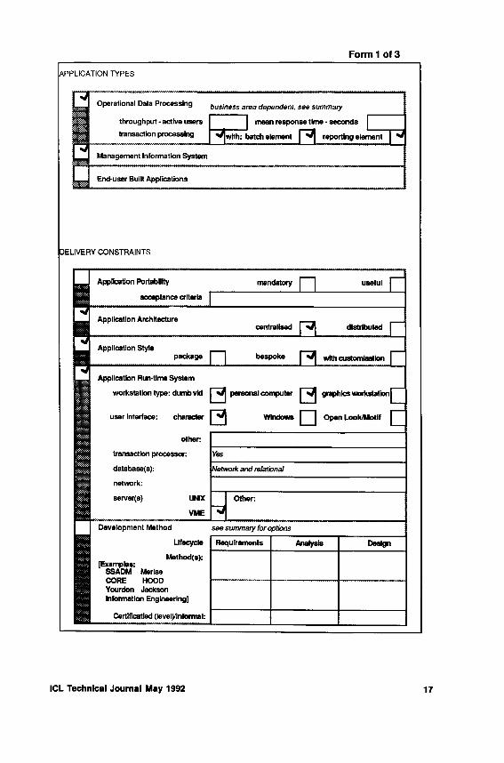
The eight steps of the method follow. The results of using the method can be formally captured and documented using the style and forms shown in the appendix with this paper. The particular illustration could be representative of a proposed solution for an ICL mainframe customer; requirements similarly documented could be matched very easily against possible solutions expressed in this way. Note form section headings are identified by text in uppercase bold (e.g. APPLICATION TYPES).
5 .1 Id e n t i fy th e APPLICATION TYPES to b e S u p p o r te d
What is the business objective for the IT system? This will identify the information that must be stored in the system and the processes and information flows needed to support the enterprise.
The scale of use for these applications, that is throughput and response time, will impact how they are developed.
Applications for both structured and unstructured data should be covered. All the information that the enterprise needs shoud be identified. The goal is always to support the enterprise and provide return on investment.
Steps 2 to 4 identify the DELIVERY CONSTRAINTS in realising these business objectives.
ICL Technical Journal May 1992 11

5 .2 D e f in e th e R u n t im e S y s te m
This will cover the appropriate IT system(s). Complexities such as multivendor systems must be recognised. This should identify key characteristics at a generic level; clearly this is not a sizing exercise!
Never confuse the runtime and development systems. The requirements of the two will, in general, be quite different. However, they are complementary - in the sense that applications must be tested and delivered for operational use; the two systems are related but only to this extent actually connected.
It is worth sketching the runtime configuration and populating it with key characteristics. Figure 2 defines a typical outline system. This can be specialised with the actual databases and transaction processing monitors, and the terminals and workstations for user interface requirements. Then the particular application architectures can be identified.
Fig. 2 Outline Run-time System
This will begin to suggest some very specific lowerCASE tool constraints that will be important. For example, high-performance transaction processing applications will need specialised tools, e.g. use of an appropriate programming language; enquiries on existing data may use tools specialised to the information source, e.g. the tools offered with a relational database.
Cover any runtime integration with IT services that must be included. Some applications may need to integrate with office systems to permit exchanges of data and provide presentation and publishing facilities. Applications may need to access information captured by an office system.
12 ICL Technical Journal May 1992
5.3 R e v ie w A p p lic a t io n C o n s tr a in ts
Certain application characteristics need to be confirmed at this stage. These cover portability, architecture and style.
Portability should be scoped carefully. Application portability with respect to database and user interface may be as important as moving platforms.
Style covers procurement issues, for example whether to purchase or develop.
5 .4 D e v e lo p m e n t M e th o d
Ensure that the importance of current skills is understood. Method training is a significant investment. Improved or new methods may be under consideration but these need to be justified on a cost-benefit basis before existing investment in a resource skill is made obsolete.
The focus for method is normally the part of the life-cycle supported by upperCASE tools.
The method to be used must be appropriate for the types of applications to be developed with supportive tooling available to an acceptable standard. Establish if method conformance levels are defined for tool support and the certification level required e.g. for SSADM see [CCTA, 1990, 1991].
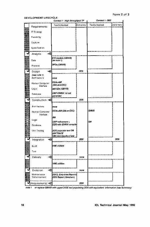
5.5 P o p u la t in g th e DEVELO PM ENT LIFE CYCLE
This exposes the development lifecycle for population with appropriate CASE tools. The lifecycle used is based on the Vee and its phases.
Each phase of the lifecycle must be considered. Identify which phases are important and any constraints on tools that will be imposed. Note some lowerCASE tool constraints for particular application types may already have been identified.
Cover the key aspects within each phase. Particular tools to be considered may have deficiencies in their coverage.
Integration needs to be exposed (ICASE). Identify the dictionary which tools need. Some may be local, others may be shared.
Identify if information can be passed between tools and across phase boundaries for subsequent use by other tools. The objective is to identify how disjoint or seamless the solution may prove to be. This will help to highlight any interfacing or bridging needs that must be imposed.
The rest is now complementing the lifecycle.
ICL Technical Journal May 1992 13

5.6 Identify the OTHER LIFECYCLE FACILITIES
Document any requirements for reverse engineering (or maintenance) and re-engineering and its extent.
Identify the use to be made of prototyping and in which lifecycle phase(s).
Define the documentation facilities needed in relation to applications development. If particular documentation will be made available to End-users then consider how this will be transmitted (e.g. office systems integration).
Accepted office facilities should be considered as part of the development environment. Identify the particular support needed, e.g. messaging facilities for team working, word processing for documentation etc.
Design information needs to be under version control and applications under configuration management. Capture the existing position and the future requirements.
5 .7 Identify the M A N A G E M E N T FACILITIES required
This covers both project and quality management. Establish the current and proposed practice and integration aspirations with technical work.
Finally, the focus becomes the development system itself which will be needed to support the CASE solution required.
5.8 Define the D E V E L O P M E N T SY ST EM
Cover the current development environment and what will persist alongside or within the proposed CASE system. Document any platform and dictionary invariants where they exist to expose this aspect for CASE tool selection.
The question of support for standards has not been exposed explicitly. This applies to both the runtime and development contexts. Where these are relevant particular support should be identified and checked against any solutions proposed.
Finally, it may be helpful to define a Roadmap for the introduction of specific CASE facilities. Some projects using a new CASE approach will initially only need upperCASE support because the analysis and design phases are lengthy. Phasing the introduction of CASE facilities enables practical incremental steps to be undertaken smoothing out disturbance and budgetary spend.
14 ICL Technical Journal May 1992

6 Conclusion
Defining and introducing CASE is both demanding and complex. But business success depends on being able to deliver the right applications to a business schedule. CASE is critical for the support of the information systems strategy of every organisation. A structured method to define the CASE requirements that can be matched against potential solutions begins to formalise CASE into its engineering discipline.
The method proposed for the analysis of CASE requirements is generic. An illustration of its use would have been equally valid for open systems. The particular experience that ICL has gained matching the CASE requirements of its mainframe customers with dictionary centred integrated tools will be carried through to the support of open and distributed system architectures.
7 Acknow ledgem ents
The author would like to thank the various members of the ICL CASE Product and Integration Centres who have contributed to the use and validation of the method; in particular to Eric H. Felton for his comments and encouragement.
References
BRUNT, R.F., FLOWER, F.L., & HUTT, A.T.F. “OPEN framework Management Summary”, ICL 1991*.
CCTA, SSADM: support tools conformance appraisal scheme, CCTA, Norwich Nov. 1990. CCTA, SSADM Version 4, An introduction, CCTA, Norwich, April 1991.HUMPHREY, W.S. “Characterising the Software Process: a Maturity Framework” IEEE
Software, 5(2) pp. 73-79, Mar. 1988.MIT 90’s, A window on the future, an ICL briefing for management on the findings o f the
“Management in the 90’s Research Program”, ICL 1990.IT-STARTS, IT-Starts developers’ guide, ISBN 0 85012 7335. NCC Publications 1989. RUSSELL, A.J. “The case for CASE”, ICL Tech. J. 6(3) pp. 479-485, 1991.STARTS, The software tools for application to large real time systems (STARTS) guide,
ISBN 0 85012 6193, NCC Publications, 1987.
Biography
Philip Vyse
Philip Vyse graduated from Oxford with a degree in Mathematics. He is a Chartered Engineer and a Member of the British Computer Society. He started out on an actuarial career but eventually changed to computing. Following experience with an oil products trading company in commercial D P he spent some years working with computer manufacturers on systems and products software. Before joining ICL he was a Management Consultant with the systems company Data Logic. His current work with ICL is involved with the technical strategy for Open CASE solutions.
•One of a series of ICL reports on OPENframework, mostly of considerable length, available on written request from S.K. Thursfield, ICL pic, Wenlock Way W. Gorton, Manchester M12 5DR, UK.
ICL Technical Journal May 1992 15
Appendix Sam ple CASE Solution
(Based on possible VME mainframe requirements beginning to introduce a UNIX element - this is an illustrative example and therefore no claim is made for either completeness or total possible coverage; note product explanations are not included.)
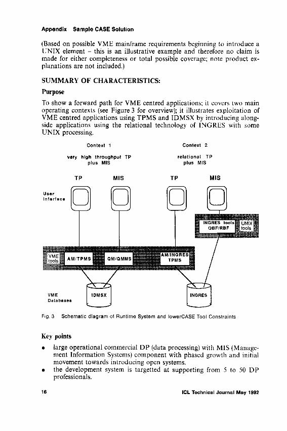
SUMMARY OF CHARACTERISTICS:PurposeTo show a forward path for VME centred applications; it covers two main operating contexts (see Figure 3 for overview); it illustrates exploitation of VME centred applications using TPMS and IDMSX by introducing alongside applications using the relational technology of INGRES with some UNIX processing.
Fig. 3 Schematic diagram of Runtime System and lowerCASE Tool Constraints
Key points• large operational commercial DP (data processing) with MIS (Manage
ment Information Systems) component with phased growth and initial movement towards introducing open systems.
• the development system is targetted at supporting from 5 to 50 DP professionals.
16 ICL Technical Journal May 1992
Form 1 of 3
DEVELOPMENT LIFECYCLEForm 2 of 3

Form 2 c o n tin u ed
Form 2 of 3 (continued)

F o rm 3 o f 3
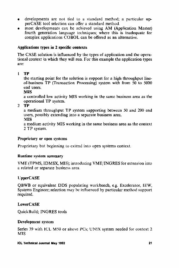
• developments are not tied to a standard method; a particular up- perCASE tool selection can offer a standard method.
• most developments can be achieved using AM (Application Master) fourth generation language techniques; where this is inadequate for complex applications COBOL can be offered as an alternative.
Applications types in 2 specific contexts
The CASE solution is influenced by the types of application and the operational context in which they will run. For this example the application types are:
1 TPthe starting point for the solution is support for a high throughput line- of-business TP (Transaction Processing) system with from 50 to 5000 end users.MISa controlled low activity MIS working in the same business area as the operational TP system.
2 TPa medium throughput TP system supporting between 50 and 200 end users, possibly extending into a separate business area.MISa medium activity MIS working in the same business area as the context 2 TP system.
Proprietary or open systems
Proprietary but beginning to extend into open systems context.
Runtime system summary
VME (TPMS, IDMSX, MIS); introducing VME/INGRES for extension into a related or separate business area.
UpperCASE
QBWB or equivalent DDS populating workbench, e.g. Excelerator, IEW, Systems Engineer; selection may be influenced by particular method support required.
LowerCASE
QuickBuild; INGRES tools
Development system
Series 39 with ICL M50 or above PCs; UNIX system needed for context 2 MIS
ICL Technical Journal May 1992 21

DETAIL:This is captured on the three types of paper form that follow together with the schematic diagram of the runtime system. Note the repeated use of the “development lifecycle” form, i.e. form 2 of 3, enables several contexts to be described.
Trademarks
INGRES is a trademark of the INGRES Product Division of ASK Incorporated. UNIX is a trademark of UNIX Systems Laboratories in the USA and other countries.
22 ICL Technical Journal May 1992

ICL’s ICASE Products
Eric Felton and Eric SoutterCASE Product Centre, Reading UK
Abstract
T h e c o m p u te r in d u s t ry a n d th e c o m p u te r u s e r c o m m u n i ty h a v e id e n t i f ie d t h a t tw o of th e b a s ic p r o b le m s a s s o c i a t e d w ith c o n v e n tio n a l c o m p u te r s y s t e m s a p p l ic a t io n d e v e lo p m e n t m e th o d s a r e th e b a c k lo g of a p p l i c a t io n s w a i t in g to b e d e v e lo p e d a n d th e c o s t of m a in ta in in g e x is t in g a p p l ic a t io n s .
T h is p a p e r d e s c r i b e s h o w ICL a d d r e s s e d t h e s e p r o b le m s w ith th e Q u ic k B u ild I n te g r a te d C A S E e n v ir o n m e n t .
1 Introduction
As businesses and organisations began to recognise the value of automating and expanding their activities by using computer application systems it became increasingly difficult to develop new applications within a useful timescale. The concept of a growing list of required applications waiting to be developed became known as the applications backlog.
The applications backlog was due in part to the complementary problem of the maintenance overhead, the expression used to describe the disproportionate amount of skills and resources devoted to the maintenance of existing applications.
ICL recognised an opportunity for a program addressing these twin problems. The result of that program is the Integrated CASE environment known as QuickBuild.
This paper sets out the aims of the QuickBuild program and describes how the components of QuickBuild combine to meet those aims.
2 The aims of QuickBuild
The aims of QuickBuild are to:
• Reduce application backlog through increased productivity;• Reduce maintenance overhead through improved quality of applications.
ICL Technical Journal May 1992 23

Increased productivity is attained by:
• Generating application systems from high level system definitions;• Using pre-defined functions and stereotyping for application code, inter
face definitions and database definitions wherever possible;• Making existing application code and systems definitions readily avail
able for re-use;• Encouraging the composite role of designer-implementor to take advant
age of improved communications possibilities in smaller development teams;
• Improving the motivation of everyone involved in application development by making visible results available in a shorter timescale.
The quality objectives are met by:
• Providing consistent definitions both within and between systems;• Introducing a methodical approach to systems analysis and design;• Encouraging cooperative working between the end-users and the ana
lysts by developing prototypes and pilots of application systems;• Generating error-prone tasks automatically such as error handling,
display screen input-output operations, database access and interactions with the transaction processing management system;
• Maintaining full system documentation.
3 QuickBuild Development History
In the mid 1970’s a strategic approach was adopted to meet the above objectives for application development. The foundation of the strategy was the ICL Data Dictionary System [Bourne, 1979]; development started in 1975 and the dictionary product became generally available in 1977.
By the early 1980’s the concepts of a Rapid Application Development System (RADS) [Brown et al., 1981] based on the dictionary were being specified; Reportmaster was the first implementation based on the RADS philosophy. Also at this time Querymaster was introduced to provide interactive, adhoc enquiry facilities.
By this time the demands of RADS made it apparent that the dictionary would have to support a greater diversity of object types than had been envisaged originally. The dictionary was re-engineered to the present architecture which allows the dictionary model to be extended easily to support new object types.
The major language component of RADS was delivered in 1984 with the release of the fourth generation language Application Master; this language formed the centre of the development environment which became known as QuickBuild.
24 ICL Technical Journal May 1992

By 1985 QuickBuild included the automatic database generator and automatic system generator components which respectively generate database definitions and application system code from high level application systems definitions. The introduction of QuickBuild Pathway provided a consistent tool interface to these generators and to the other components of the QuickBuild environment. Pathway was designed to lead the user through the steps involved in producing a QuickBuild application.
The introduction of QuickBuild WorkBench in 1987 allowed the high-level definitions of application systems to be represented graphically as models on a personal computer workstation; an interactive link allowed the models to be interchanged between the WorkBench and the mainframe dictionary.
An exploitation guide was produced in 1989 based on the experience gained in the use of the QuickBuild tools.
1990 saw the integration of the INGRES relational database management system into the QuickBuild environment with the introduction of a database generator for INGRES and the ability to access INGRES databases from Application Master programs.
The introduction of the FORMS system in 1991 provided the capability to build TP applications with a Graphical User Interface as an alternative to the original character-based screen interface.
Most recently the ability to interchange design information between the ICL dictionary and the CASE tools of leading third party suppliers has offered a choice of systems analysis tools which will integrate with QuickBuild.
4 ICL Data Dictionary System
The ICL Data Dictionary System (DDS) is a central dictionary (or repository) for application development. In effect it is the database for the applications used by the data processing department.
DDS provides a standard set of element definitions which:
• enable integration between the components of the QuickBuild productset;
• enable cooperation between DDS and the dictionaries of CASE tools which are not specifically aimed at the ICL application development environment.
Application definitions are shared between analyst workbenches, design workbenches and programming workbenches by use of the DDS during the analysis, design and construction phases of the application development lifecycle; the application development tools used in the construction and integration phases of the application development lifecycle use these defini-
ICL Technical Journal May 1992 25
tions to build the Human Computer Interface (HCI), Application Logic and Database for the application under development.
4 .1 DDS A rc h ite c tu r e
Data in DDS conforms to the 4-layer Information Resource Dictionary System (IRDS) framework architecture [ISO/10027], In this architecture the types of data that can be stored at each level are defined at the level above as follows:
• the fundamental level defines the concepts used in storing and maintaining dictionary information;
• the IRD definition level defines the types of data that can be held in the IRD level; DDS includes a standard set of over a hundred data types which are referred to as element-types; new element-types may be added by the user;
• the IRD level defines the data that exist outside the dictionary; DDS objects at the IRD level are referred to as elements;
• the application level is outside the scope of the dictionary but is included in the architecture to show the purpose of the IRD level; this level consists of occurrences of objects which are defined at the IRD level.
A database table for CUSTOMER records would be represented below the fundamental level as follows:
• IRD definition level element-type TABLE• IRD level element CUSTOMER of element-type TABLE• application level customer records in the format of element
CUSTOMER
4.2 The DDS Model
DDS elements can be divided into four categories (Figure 1); processes and data at the business or real world level and processes and data at the computer implementation level. The business level elements usually record the results of a business analysis; some, such as Entity-Life-History-Node for SSADM, are specific to particular methods while others such as Entity and Operation are method independent.
The implementation level elements represent the computer application; elements at this level are used by other tools in the construction of applications.
Every DDS element is described by its properties. Some properties such as DESCRIPTION apply to all element-types while other properties such as the ORGANISATION property of the File element-type are unique to a particular element-type. Most element-types have properties which define links between elements of different types; for example the Attribute elements
26 ICL Technical Journal May 1992
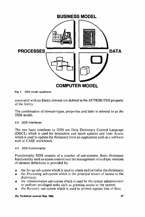
Fig. 1 DDS model quadrants
associated with an Entity element are defined in the ATTRIBUTES property of the Entity.
The combination of element-types, properties and links is referred to as the DDS model.
4 .3 D D S In te r fa c e s
The two basic interfaces to DDS are Data Dictionary Control Language (DDCL) which is used for interactive and batch updates and User Access which is used to update the dictionary from an application such as a software tool or CASE workbench.
4 .4 D D S F u n c t io n a lity
Functionality DDS consists of a number of sub-systems. Basic dictionary functionality such as access control and the management of multiple versions of element definitions is provided by: •
• the Set-up subsystem which is used to create and initialise the dictionary;• the Processing subsystem which is the principal means of access to the
dictionary;• the Administration subsystem which is used by the system administrator
to perform privileged tasks such as granting access to the system;• the Recovery subsystem which is used to protect against loss of data;
ICL Technical Journal May 1992 27

• the line editor and screen editor which are used to modify elements in the dictionary.
The other subsystems provide direct support for CASE as follows:
• the COBOL preprocessor generates COBOL data definitions from the dictionary into the source of COBOL programs; the processor was one of the earlier applications of the dictionary and has recently been extended to generate COBOL data definitions from INGRES database definitions in addition to the original conventional file definitions;
• the utility system generates selected subsets of dictionary data as DDCL; DDCL thus generated may be re-input to other dictionaries or may be converted to another proprietary design interchange format (DIF) for input to third party workbenches and dictionaries;
• the take-on system generates dictionary definitions from the data definitions in COBOL source programs, from TPMS screen templates and from the schema and subschema definitions of the original 24 bit IDMS systems; although originally intended as a transition tool for IDMS applications being migrated to VME, the take-on system exhibits some of the features associated with reverse engineering.
Basic DDS functionality is extended by optional DDS facilities as follows:
• DDS System Definition Language extends the DDS model to support the design objects associated with the Structured Systems Analysis and Design Methodology (SSADM);
• D D S User Extensibility allows the addition of user defined extensions to the DDS model;
• Multiple Project Management extends the basic version control facilities by allowing groups of elements to be defined and treated independently;
• D D S User Retrieval and DDS User Access respectively allow read and update access to the dictionary from COBOL applications.
4 .5 D D S s u p p o r t fo r d e v e lo p m e n t
The Data Dictionary System supports the input and retrieval of process anddata definitions from the types of tools shown in Figure 2.
The tools and methods currently supported by the DDS model are:
• languageCOBOL Compiling System, ANSI 74 Application Master (AM)Reportmaster (RM) •
• Human Computer Interface DDS Screen Designer FORMS
28 ICL Technical Journal May 1992

Fig. 2 C la s se s of to o ls su p p o rte d by DDS
• d a ta b a se m anag em en t a n d accessIntegrated Database Management System (IDMS and IDMSX) Querymaster (QM)Relational CAFS Interface (RCI)Direct CAFS Interface Plus (DCI PLUS)INGRES database management system INGRES Database Generator (IDBG)AM/INGRESINDEPOLICLFILE
ICL Technical Journal May 1992 29

• transaction managementTransaction Processing Management System (TPMS)
CASE toolsQuickBuild WorkBench (QBWB)QuickBuild Pathway (QBP)
• methodsSSADM, Structured Systems Analysis and Design Methodology HOOD, Hierarchic Object Oriented Design CORE, Controlled Requirements Expression
5 The QuickBuild Development Cycle
Many of the products supported by DDS are components of ICL’s fourth generation application development environment, QuickBuild; DDS is the fundamental component of the QuickBuild development process.
The QuickBuild development cycle is analogous to the more general application development life cycle models [Russell, 1989]. The stages of the QuickBuild development cycle are:
• Statement of user requirements: a formal definition of the needs of the users who are requesting the computer application;
• Analysis of the business: an analysis of the flow of information within and between the departments of the user’s business;
• Production of a prototype: an optional stage producing a prototype to validate the analysis or clarify design decisions;
• Design: a detailed plan showing how to implement an application for a chosen aspect of the business;
• Implementation: the realisation of the design as a computer application;• Going live: the users’ adoption of the application for productive work;• Maintenance and adaptation: a continuing process of modification and
enhancement to match the changing requirements of the users and the business.
5 .1 Q u ic k B u ild A n a ly s is
In analysing the users’ requirements the analyst investigates primarily the flow of information and the processes performed within the business. The scope or boundary of the potential computer application is defined in order to differentiate between the internal processes and data which will be handled by the application and the external processes and data which will interact with the application.
From a study of the people in the organisation, the processes that they perform and the information that they use to do their job, the analyst can draw a Data Flow Diagram. This model represents the process view of the
30 ICL Technical Journal May 1992

application and shows the flow of information across the application boundary and the processes and types of data within the application boundary.
In parallel with the production of the Data Flow Diagram the analyst collects information to construct an E n tity M odel. This model represents the data view of the application in terms of entities and relationships; entities are objects which have significance to the organisation, for example EMPLOYEES, CUSTOMERS and SERVICES. Relationships are represented as connections between entities and serve to define each entity in terms of its significance to other entities, for example, the simple relationships between CUSTOMER and SERVICE and between SERVICE and EMPLOYEE might be stated as:
• a CUSTOMER may request a SERVICE• a SERVICE must be provided by an EMPLOYEE.
The individual characteristics of entities are further defined by their attributes, for example, some attributes of SERVICE might be name, description, duration and cost.
QuickBuild WorkBench can be used to draw the Data Flow Diagrams and Entity Model diagrams and to record definitions of diagram objects.
5.2 Q u ic k B u ild P ro to ty p in g
Prototyping may be regarded as the final step in the analysis stage or as the preliminary step in the design stage. Building a prototype application enables the analyst to validate the conclusions from the analysis stage and provides guidance to the designer.
Prototyping is supported by Q u ickB u ild P a th w a y . The process and data views of the business, represented by the Data Flow Diagrams and Entity Model diagrams, can be exported from QuickBuild WorkBench into the dictionary. The A u to m a tic S y s te m G enera to r and automatic database generator components of QuickBuild Pathway can be used to transform these business-level models into the corresponding implementation-level representation in the dictionary. Automatic System Generator creates a prototype application with Application Master code and screens; the database generator creates a prototype database definition. QuickBuild Pathway invokes compilers to generate the run-time code for the application and database.
Experience gained from using the prototype is used to refine the analysis and to influence subsequent design decisions.
5.3 Q u ic k B u ild D e s ig n
The objective of the design stage is to take the business level definitions resulting from the analysis stage and convert them to a definition of processes
ICL Technical Journal May 1992 31

and data which can be implemented as a computer application. The design activity involves an intuitive interpretation of established guidelines for the chosen implementation environment.
The products of the QuickBuild design stage are:
• Application Master structure diagrams;• Screens and report layouts;• Database structure diagrams.
Application Master is ICL’s fourth generation language. It allows applications to be defined in a high level declarative language and enforces a top down approach to application design. The processing structure of an Application Master application can be represented diagrammatically as a series of processing elements which are executed sequentially, selectively or repeatedly; this representation of process logic is similar to Jackson program structure notation.
QuickBuild WorkBench can be used to draw the Application Master structure diagrams and record code definitions of the processing elements. The application elements can be interchanged between the workbench and the dictionary; for example, a successful prototype application can be imported from the dictionary and automatically generate a structure diagram in the workbench; completed structure diagrams are exported to the dictionary for implementation.
Many of the applications in commercial data processing involve a series of interactions, or dialogue, between the end-user and the computer with information entered and presented on pre-formatted display screens. QuickBuild designers can develop screen formats using the DDS Screen Designer for character based screens or the FORMS Interface Designer for graphics based screens. In both cases the resulting screen formats are recorded in the dictionary.
QuickBuild applications can access either IDMSX network databases or INGRES relational databases. The database designer creates the implementation level definition of the database from the Entity Model.
Database design can be considered in two separate stages. In the first stage the entities, attributes and relationships from the Entity Model are represented as IDMSX records, items and sets or as the table structure and column definition of an INGRES database. QuickBuild supports this transformation with the automatic database generator for IDMSX and the INGRES Database Generator for INGRES; in the second stage the designer alters the dictionary definition of the generated database design to take account of factors which will affect performance such as data volumes and application access paths.
32 ICL Technical Journal May 1992

5 .4 Q u ic k B u ild Im p le m e n ta t io n
The implementation stage transforms the design from a dictionary model into a working application.
Process code is added to the elements identified in the application structure diagrams and the applications are compiled; physical storage information is added to the database design and the database run-time definitions are generated; the run time components of the HCI are generated; the TPMS components are defined in the dictionary and the run time TP definition is generated.
The database implementor can also provide ad hoc enquiry facilities for IDMSX databases using Querymaster. A simplified view of the database, known as an end-user view, is constructed in the dictionary; this view controls the scope of the users’ access to database information and allows database information to be accessed using terms which are familiar to the end-user. The end-user view is compiled to produce a query view; Query- master uses the queryview to allow end-users to interrogate the database interactively.
5 .5 P o s t - Im p le m e n ta t io n S ta g e s
The implementation stage delivers a working computer application to the end-user department which will be responsible for day to day operation. The QuickBuild method provides guidelines for the tasks such as database loading and user training which are needed to bring the application into live use.
The application is unlikely to remain unaltered for long; some of the required functionality identified during analysis may have been deferred until after the initial implementation and, over time, the requirements of the business will change and the application will need to be adapted to match these new requirements.
The development cycle may be reiterated from any stage in order to modify and extend the application. Since the entire application definition is recorded in the dictionary it is possible to make automatic assessments of the impact of any change to the application. The dictionary definition of the application can exist at several versions to allow the operational application to be maintained while the extended application is being developed. The use of a common dictionary base for all components of the application ensures that the changes will successfully integrate with the existing application.
ICL Technical Journal May 1992 33

The success of QuickBuild should not be put down solely to the technical capabilities of the product. No CASE product is viable without good marketing and supporting services.
To ensure that QuickBuild remained ahead of the competition, a strategy of incorporating leading edge ideas and techniques was adopted - these include the use of dictionary and declarative language. This meant that basic concepts had to be explained to potential customers before even mentioning products. For example, although the data dictionary is actually a powerful documentation tool, it would be wrong to see it merely as an overhead that users had to accept to make use of other products. It is interesting to note that in the UNIX world many customers are less advanced than those using VME; old presentation slide sets explaining some of the concepts behind QuickBuild are being dusted off to use again.
The marketing strategy for QuickBuild was broadly to aim the product at medium sized customers those with in-house development resource of about 20 or 30 staff. The very large customers were reluctant to move away from traditional tools, claiming that QuickBuild could not cope with their performance and complexity requirements. It should be noted that now the product is mature and has a proven track record these customers are beginning to embrace QuickBuild. Smaller customers tend to procure packages.
QuickBuild was promoted as a complete approach to building “line of business” data management applications the method and techniques being emphasised as much as the software. T ra in in g courses and expert co n su lta n cy services were made available from the first introduction of the products. To ensure that knowledge was always up-to-date, skills transfer workshops for each new release were developed and delivered by the QuickBuild development team. The skills generated in the field proved vital for supporting a product of this complexity.
The most effective sales technique was called the Q u ickB u ild in A c tio n D ay. At these events prospective customers were invited to ICL’s premises bringing with them the bare bones of a small application that needed to be built. A skilled ICL consultant would sit down with the customer staff and quickly build the required system (or a part of it) - explaining all the tools and techniques used as they went along. This selling method was very successful with almost every customer attending such an event later ordering the product.
The QuickBuild in Action idea was on one occasion even run on a conference exhibition stand. Delegates would leave a basic entity model with the consultants manning the stand and return a few hours later for a demonstration of their completed application.
6 QuickBuild - Marketing and Supporting Services
34 ICL Technical Journal May 1992

7.1 S k i l ls R e q u ir e m e n t s
Initially the training courses did not go to sufficient depth - particularly in the programming area. As a result of this, some users attempted to program with the AM 4GL in a COBOL style and the full productivity benefits were not realised. Over time, experience was gained and the courses were adjusted; nowadays they meet the real requirements and are proving very successful.
In retrospect QuickBuild has not significantly deskilled the application development task - a high degree of knowledge is still required. However, people with the necessary skills can be very productive compared with those using conventional methods. This situation has not changed and is true of most CASE tools - they can deliver good results but in the wrong hands offer little benefit. This lesson remains a challenge to the industry. The learning curve required for CASE is too great - new techniques will be required to overcome the shortage of skills in the future.
7 .2 P ro d u c t iv ity B e n e f its
The original productivity claims for QuickBuild can be met in the construction of applications. However, little improvement was gained in certain other areas of the application development lifecycle, for example, Requirements Analysis at the start and System Testing and Delivery at the end. Overall productivity gains of 50 or 100% can be made - but the enormous improvement many vendors claim is still far from achievable without addressing the complete lifecycle.
7.3 E n d U s e r P a r t ic ip a t io n
The participation of end users in the development process was stressed as an important improvement that QuickBuild provided. It is a valuable technique but in many cases has proved difficult to do. An effective prototyping approach which does not involve rework is still required.
7 .4 T h e S tr u c tu r e o f th e D e v e lo p m e n t T e a m
The customers who are achieving the best results with QuickBuild are those who have amended the organisation of their development shops. Small teams with full responsibility for the complete development of an application area have proved more successful than those using separate units for analysis, screen design, coding, testing etc. This team structure will be further strengthened with the introduction of object oriented techniques - with work groups encapsulating their areas of responsibility. This gives freedom for initiative internally while presenting well defined interfaces externally.
7 Lessons of QuickBuild
ICL Technical Journal May 1992 35
7.5 R e d u c e d M a in te n a n c e
QuickBuild has proved very successful in reducing maintenance costs. The dictionary-centred approach has ensured that applications are well documented. However, applications developed using Quickbuild form only part of most customer systems - full integration with existing applications and bought-in packages has proved difficult and remains a time consuming and labour intensive task.
7 .6 In c r e a s e d M a c h in e U s a g e
One valuable lesson learnt from QuickBuild is that CASE tools consume large amounts of machine resources. This is only to be expected since by definition C om pu ter A id e d Systems Engineering tools use the computer for work that would otherwise have been done manually. This fact was not explained to early QuickBuild customers and some major problems had to be resolved. Managing expectations is all important - customers do realise that nothing comes for free.
Nowadays expectations are better managed and it is common to use dedicated machines for application development. However, despite the continuing advances in hardware performance, CASE can be relied on to consume significant processing resource.
8 CASE Partners
In the CASE arena ICL’s commitment to Open Systems is demonstrated by the evolution of an in teg ra ted and open C A S E solution. This solution recognises the need for freedom of choice in the selection of CASE tools from specialist suppliers and requires that the selected tools be supported by a dictionary to provide continuity and control throughout the application development lifecycle.
The CASE Partners Programme provides a framework for cooperation between ICL and selected third party CASE tools suppliers. Such collaborations can be directly beneficial to the partnership, for example, when conducting joint promotional campaigns; on the other hand customers also benefit from the partners’ joint understanding of their requirements and from the availability of interworking products.
At present the CASE Partners are:
Learmonth & Burchett Management Systems pic (LBMS)Ernst & Young CASE Technology (UK) Limited Hoskyns Group pic PA Consulting Group Intersolv IncNational Computing Centre (NCC)
36 ICL Technical Journal May 1992

Softlab Limited Software One Limited
The software tools provided by these CASE Partners support the following development lifecycle activities:
Business planning and IT strategySystems analysisDesignRe-engineeringProject lifecycle supportProject and resource management
As an example of product interworking the analyst workbenches of Ernst & Young, LBMS and Intersolv may interchange data models with the ICL dictionary using the Exchange transformation tool from Software One.
9 Future Challenges
The Open Systems world is a very different place from the cosy proprietary environment in which QuickBuild operates. ICL itself has been able to develop most of the tools that sit around DDS - and a very close integration has been achieved. In the Open Systems world users will expect to have a far wider choice of tools with the same degree of integration. The demand from users is to gain continued improvements in productivity and quality through the use of their chosen tools.
ICL aims to meet the challenge of Open Systems through the use of CASE Scenarios and the Open Dictionary. Scenarios will define certain ICL- endorsed combinations of tools, each being aimed at a different application type; the Open Dictionary will provide control and documentation for the full lifecycle, including integration between CASE tool sets.
Trademarks
INGRES is a trademark of the INGRES Product Division of ASK Incorporated. UNIX is a registered trademark of UNIX Systems Laboratories, Inc. in the USA and other countries.
References
BOURNE, T.J. The data dictionary system in analysis and design. ICL Tech J. Vol. 1 Issue 3, pp. 292-298 (1979).
BROWN, A.P.G., COSH, H.G. and GRADWELL, D.J.L. Development philosophy and fundamental processing concepts of the ICL Rapid Application Development System RADS. ICL Tech J. Vol. 2 Issue 4, pp. 379-402 (1981).
RUSSELL, A.J. The Case for CASE. lCLTech J. Issue 6(3), pp. 479-495 (1989).ISO 10027 Information Resource Dictionary System (/RDS) framework.
ICL Technical Journal May 1992 37
Bibliography
ICL, QuickBuild: Overview. 1CL Publication Reference Number 11124/003, Third Edition for QuickBuild 3.7, October 1991. (This publication provides a cross reference to the complete set of QuickBuild technical publications.)
ICL, Data Dictionary System Overview, ICLPublication Reference Number CS3500, May 1991.
Biographies
Eric Felton
Eric Felton gained a degree in physics from Imperial College London in 1978 and joined ICL at the end of the year. He first contributed to the development and support of the Codasyl database system IDSMX. He then worked on the design and development of the Rapid Application Development System; from which the Reportmaster and Application Master products were produced.
During 1985 and 1986 he produced exploitation material and provided consultancy services for QuickBuild. Since then he has held marketing roles, taking on product marketing responsibility for QuickBuild in 1989. He has managed the requirements specification and market introduction for the integration of QuickBuild with INGRES and FORMS. He is currently product marketing manager for ICL’s Open CASE strategy.
Eric Soutter
Eric Soutter joined ICL in 1978 on completion of a five year project for the Ministry of Defence. During the subsequent years he worked on the development of application systems for ICL customers, both in a consultancy role and as a member of development projects, using a variety of target database management systems and a varying degree of CASE tool support.
For the last two years he has worked in the CASE Product Centre with responsibilities which include integration between the CASE tools of specialist third party suppliers and the ICL CASE environment.
38 ICL Technical Journal May 1992

The Engineering Database
David Clarke, Keith Matthews, John PrattICL Secure Systems, Winnersh, Berks, UK
Abstract
A p p lie d to s o f tw a r e d e v e lo p m e n t t h e te r m E n g in e e r in g D a ta b a s e m a y n o t b e u n iv e r s a l ly fa m il ia r . In th is p a p e r it d e n o t e s a m e a n s of m a n a g in g a ll fo rm a l in fo rm a t io n a b o u t a s y s te m d e s ig n . It is c o n c e iv e d o f a s s u p p o r t in g t h e d i s c ip l in e s c la s s ic a l l y a s s o c i a t e d w ith t h e d r a w in g o ff ic e in a m e c h a n ic a l e n g in e e r in g c o n c e r n , s p e c i f i c a lly , t h o s e o v e r r e c o r d in g , a u th o r i s in g a n d i s s u in g a ll c h a n g e s to a p r e v io u s d e s i g n w h e th e r t h e y a f fe c t m a te r i a l s , c o m p o n e n t s , o r m e th o d s o f m a n u f a c tu r e o r a s s e m b ly .
T h e c o n c e p t s a n d c h a r a c t e r i s t i c s o f a n “ E n g in e e r in g D a t a b a s e ” a r e e x p lo r e d f ro m t h e u s e r s p e r s p e c t iv e , c la s s i f y in g th e c u r r e n t p r a c t i c e s o f u s e r s , t h e f a c i l i t ie s n e e d e d to h e lp th e m , a n d th e e s s e n t i a l f e a t u r e s o f a d a t a b a s e s u p p o r t in g s u c h fa c i l i t ie s . T h e p a p e r d e s c r i b e s a n e x p e r im e n ta l s y s te m w h ic h is c u r r e n t ly u n d e r e v a lu a t io n .
1 Introduction
Although databases are well understood mechanisms, the term “Engineering database” is less well defined. We have used it to denote a means of managing all formal information pertaining to a system design. We conceive it as providing the discipline one associates with a “drawing office”, that is, emphasising the identity and stability of components and structures.
The requirements of a database for engineering applications have been published in [Lockermann et al, 1985]. This paper applies those requirements to the world of system design.
2 Database? - What database?
All software developers hold a database of information about their projects. The problem is that this data is spread over several sets of files and/or ‘real’ databases and/or paper documents, and tends not to be recognised as a
ICL Technical Journal May 1992 39
database. It may even be held in the developer’s head and nowhere else (despite management urgings to the contrary).
The form this database takes varies quite widely, and is often tied to the size of the project or group of projects, or the nature of the development environment. The time that the project has been running is often (but not universally) a deciding factor, process maturity is much more important.
In this paper we shall first examine the range of tools and practices in current projects, second list the required features of a database, and third discuss our current experiment of providing such facilities.
3 Current Practices
3 .1 T h e to o ls
Depending on the platform, the following types of product are available, each providing some form of data management:
(a) Data dictionary system or repository. These provide storage and retrieval of information via a predefined schema. A full data dictionary provides for requirements processes and data as well as implementation processes and data (see Bourne, 1979 and Appendix A).
(b) Relational 4GL systems. These have an inbuilt data dictionary, but it normally handles only the implementation data and some implementation processes relevant to the 4GL itself. This is often termed ‘Lower CASE’ information (cf requirements information which is termed ‘Upper CASE’).
(c) Self-contained CASE tools for analysts, designers and project managers. These hold information for their own specific purposes only, and in a form that is most convenient to the tool producer.
(d) Self-contained configuration management tools (e.g. PCMS from SQLI systems) or source control tools (e.g. SCCS), or build management tools (e.g. MAKE). These are basically concerned with managing the uniqueness of code modules and similar objects.
(e) Word Processing and/or office automation systems, editors, compilers, Test Specification generators and automated testers, and similar type tools. These invariably operate on files, and may be regarded as information generators.
(f) Miscellaneous other tools, usually of a site-dependent nature and locally produced.
Examples of these products are:
(a) ICL’s Data Dictionary System (DDS), the Oracle CASE repository, and
40 ICL Technical Journal May 1992

IBM’s Repository Manager. PCTE (the Portable Common Tools Environment) is an up and coming member of this group.
(b) The well known Ingres, Oracle etc.(c) The range here is enormous, Examples well known in the UK are
Automate Plus, IEW, and PMW (all running on PCs), with Cadre’s Unix based Teamwork well known in Continental Europe and the USA.
(d) SCCS is well known to many Unix developers, with PCMS and PVCS being more comprehensive alternatives. MAKE is also well known in Unix and PC environments.Interestingly, most of this group of tools tend to exist in Unix or PC environments only, and not on mainframes. One exception is the system built into the ICL QuickBuild product set to control the compile dependencies for IDMS(X) and Application Master.
(e) An enormous range. The problem is that the files which support these products are not thought of as contributing to the project database despite the vital descriptive information held in text documents. Many are platform specific.
(f) Site or product specific build control, document generators, and code management utilities have been seen. Many more must exist somewhere, unknown outside their sites of origin.
3 .2 E n v i r o n m e n t a l fa c to rs
There are many factors which influence the way that projects use data management and how well they integrate with them.
(a) Technical capability.One factor is centred around the technical capabilities of the products involved. These determine the ability of the repository (the central integrated part of the total engineering database) to hold information from all four of the defined quadrants defined in Appendix A, or the ability of tools to interface to the repository.
This is heavily influenced by the reluctance of some tool vendors to address the interfacing issue, and the tendency of some projects to buy on appearance rather than capability.
(b) Process Maturity.The processes that one uses to move from one stage to another are very important, although this is only just becoming obvious. The IPSE 2.5 work [Warboys, 1989] has examined some aspects of the field, and is among the leading edge of that type of technology.
The main message is that, to be certain of the value of taking a step, one must have not only good people, one must have a well defined transformation which can be reproduced.
Very few projects can be regarded as having thoroughly mature processes; those that can are normally long running.
ICL Technical Journal May 1992 41

(c) Size of project.This is another criterion, but is closely related to process maturity in that large projects see the need for well defined processes sooner. However not all progress beyond simply reducing the chaos to a manageable state.
(d) Platforms used.The mix of platforms used is another factor, although some sites are reluctant to use to best advantage what networking facilities are available.
3 .3 C a te g o r ie s o f u s e rs
For the sake of a classification which does not cause confusion we have chosen to base it on use of all of the dictionary quadrants (i.e. holding requirements information as well as implemented system information) together with CASE and support tool usage. This does need value judgements but these are not very significant.
The five categories decided upon can be described as follows:
(a) Totally integrated.This is the situation where a dictionary is used, and all types of tool defined above interface with it. An interesting point is that the technology forces adoption of very mature processes.
(b) Highly integrated.This group use a data dictionary (or repository) with all four quadrants populated together with CASE tools. Most or all of the tools use the dictionary either as a backup repository, or as their primary repository. Process maturity need not be high here, but does tend to be so.
(c) Loosely integrated.This is the group who either do not populate all quadrants of the dictionary (perhaps because their dictionary does not support all four), or they do not have tools integrating with it. Process maturity is usually medium, except with those projects that have been running a long time.
(d) Standalone Products.These are the projects who do not have dictionaries, and whose CASE tools (where used) are standalone. CASE tool usage tends to be from types b, c, and e only.
Process maturity tends to be low to medium, prototyping tends to be extensively employed as a development route.
Projects in this group do record all information, which sets them apart from the final group.
(e) Total lack of integration.This group use little or no CASE tools beyond editors and compilers. Freestanding word processors are used for what little documentation is produced.
42 ICL Technical Journal May 1992

Process maturity tends to be very low, with written specifications rarely in evidence.
It is noticeable that Information Systems developers tend to fall behind the large embedded real-time developers (e.g. the ESA Columbus and Hermes projects) in many of these matters. Certainly the latter lead the way in terms of CASE usage, configuration management and process maturity, but they do tend to lag in terms of dictionaries.
3 .4 R e a l P r o je c t P r a c t ic e
Usage of these among ICL’s clients is typical of Information Systems sites world-wide and is divided among the categories as follows:
(a) T o ta lly in tegra ted .There are no known projects in this group.
(b) H ig h ly in tegra ted .This group is primarily composed of large project sites, usually central government or public utilities, also ICL’s internal MIS providers, and is almost exclusively VME based. They are almost invariably based around ICL’s DDS product, and tend to have dictionary sizes in excess of 300 Mb (up to 5 Gb in one instance). The more sophisticated Quick- Build users also belong here.
Apart from the normal four quadrants most also hold some other types of information, but there is no consistency between them as to what types. Many have their own special tools that talk to the dictionary via the USER RETRIEVAL or USER ACCESS interfaces. Apart from this, access to the dictionary tends to be via the normal direct interactive mechanism or batch files.
A small number of sites use Design Master, but the majority of those who use CASE tools use ones that integrate much less tightly.Version management is used in a well controlled manner, but not always using the standard mechanism.
Configuration management and build control tend to be either manual or via locally produced tools external to the dictionary, and are often not as tightly controlled as they might be. At least one project is known to have worked out a scheme to drive builds from the dictionary, but that was never implemented. The products in the QuickBuild set have their own mechanism internal to DDS, but this is not easy to integrate with other parts of the development.
Even in this group, no project is known to hold Project Management information in the dictionary, although one of ICL’s bespoke projects did do so some 10 years ago. One vendor of project management tools is examining the possibility of linking to DDS.
ICL Technical Journal May 1992 43

(c) L o o se ly in tegra ted .This is a much more diffuse group. While most are on VME the group also includes the more advanced UNIX users.
As is well known, ICL’s internal VME development group use CADES. This is comparable with DDS but has no ability to hold requirements information, forcing the team to use paper based methods. It is also weak in support for and by analysis and design type CASE tools. On the other hand it is much stronger in terms of its ability to control builds and manage the configuration. Again project management information is held in free-standing tools. This is an example of a project with very mature processes which has not yet achieved a high degree of integration.
Many QuickBuild users also fall into this category, although few actually use the possibilities for configuration management that working almost entirely in the dictionary gives them. Configuration management tends to be carried out in a more relaxed manner, and build control tools are almost never used. Not all sites use version management. Usage of CASE tools tends to be low profile here also.
UNIX users tend to lack the more integrated facilities available on VME, but have a much wider range of tools to help them. Few of the UNIX users have dictionaries. Relational products are more difficult than DDS to apply configuration management to, although one of ICL’s consultants has worked out a method. Version management is available, but requires more explicit specification from the user than DDS. Other than this, requirements information tends to be on paper where used (prototyping is the more usual method). Build control for relational products is almost non-existent, the attitude of most developers being that it is not needed.
Free-standing Configuration Management tools are available for UNIX, and the more advanced non-relational developers use them (an example is detailed below). These tools are difficult to use for controlling relational systems or any database, but valuable experience has been gained to help define the next generation of products. Attempts have also been made to control VME builds via this route, but no real success can be reported as yet.
Experiments are being carried out with a view to controlling the data held by Project Management tools. ICL’s Winnersh team are also looking at applying configuration management to UNIX-based CASE tools, in this instance products based on IPSYS Tool Builders Kit.
Unfortunately, the free-standing Configuration Management databases are a little ponderous in their style when it comes to holding very fine grain information, so impact analysis tends to be available only at the
44 ICL Technical Journal May 1992

module interaction level (as opposed to the within module level available from DDS). This is what currently prevents Unix sites being regarded as among a higher group.
Despite the relative lack of control, these sites tend to survive well. The small project teams that typify them make the problems of intercommunication much less acute.
(d) T h e S ta n d a lo n e p ro d u c ts group.This group could be described as the traditionalists. They include all VME projects making minimal use of DDS, together with the majority of UNIX sites using relational systems. It also covers a small number of PC sites.
The VME projects tend to use the basic VME file management facilities, perhaps with extra usernames or file groups or libraries to differentiate between live and development code. Again they tend to have small project teams, so control is less difficult. Often they are now in maintenance-only mode, with the systems often prime candidates for redevelopment through age.
Requirements information is invariably paper held, so the biggest problem tends to be keeping it in step with the system.
All relational systems have a form of data dictionary, although it is restricted to the run-time information. Since most projects tend to develop in a prototyping manner this is usually not seen as being important, however documentation of the requirements is often the only way to prevent arguments between user and DP departments over which facilities were asked for. This is trebly important where the requirements of different user departments may clash.
UNIX developers of non-relational systems tend to rely on SCCS as a configuration management facility. When compared with products such as PCMS this is seen to be sadly lacking in both build structure recording and life cycle management facilities, it’s main advantage is that it comes free with UNIX.
CASE tools are either not used, or are freestanding, often on PCs. This is true of Project Management tools also.
The upshot of this is that impact analysis is almost impossible in a sensible manner, as is version management. A very small number of PC developers creep into this bracket by virtue of using Configuration Management tools such as PVCS.
(e) T h e u n in teg ra ted group.This is the group who often refer to themselves as ‘Real Programmers’, ignoring the fact that programming is only part of the task. They are usually PC based, but some have graduated to UNIX boxes. They see
ICL Technical Journal May 1992 45
any sort of tool beyond an editor or compiler as ‘unnecessarily complex’ and ‘preventing creativity’, and are blind to the fact that the industry needs engineering rather than creativity.
These people will only survive safely if they restrict themselves to single developer projects.
4 Why move on?
This question is often asked by those who have never used a proper repository. However the feeling of certainty and safety such a tool gives a developer is enormous. One can always be certain that a definition exists or does not (as opposed to ‘may exist’), and that if two developers are using the same item then they are using the same definition of that item.
In a maintenance or incremental development situation the biggest problem is evaluating the potential impact of a proposed change. When everything is in a repository the question is fairly easy to answer - because the repository knows about the usage of each object instance by all others. There is also a much greater tendency to ensure that the documentation is up to date, and it is much easier to check that the requirements can be traced down through the system design and implementation.
If we move on and start adding other project information such as the project management, then the project manager can have the same certainty of his project plans relating to the reality of development work. Each team leader can be sure which version of the plan and requirements he is supposed to be working to. And everyone can be sure that no hardware failure has put any part of the total project data significantly out of step with any other.
The situation becomes even more complex when several designers are working together, and coordination of their various parts of the overall design becomes essential. Even the nam es of items need management to avoid conflict and promote consistency of naming across the design team.
Most of these features are available to any project with a good repository, however CASE tools add their own urgency to the problem. One of the main advantages of CASE is to allow multiple versions of designs to be created and explored with minimal time and effort. Often these involve references being made between one part of the design and another. This generates large volumes of complex information, and as all database people know that needs careful management.
A further difficulty for the user is that CASE tools often use the filing system of the workstation to record the design, including explicit file-to-file references in the files. This approach hides the structure of design and inhibits other tools making use of the structures. It is often necessary to arrange the conversion and export of design information from one tool to another to
46 ICL Technical Journal May 1992

avoid difficulties of tools having private structures. The user then loses the benefits of automatic tool coherence, and incurs the extra time and effort in managing the transfers between tools.
Taking account of the above problems and assuming that the user should concentrate on the nature of the design whilst minimising the attention given to housekeeping, then automation of the information administration is obviously of value. Rather than being a hindrance, good administration stimulates creative design.
This leads us to the recognition of the benefit of a central structured database, which preserves and organises the design detail and supports access by many tools. Unfortunately it is not easy to implement such a database because of the nature of the design structures and the type of access which designers desire, and most attempts at using conventional database technology have not been successful. The concept of an “Engineering Database” has therefore emerged as one which is optimised to solve this problem.
This concept is portrayed in Figure 1, which illustrates the way in which different parts of the project organisation look at the total data set. The project manager would be interested in the Work Breakdown Structure (WBS) and Product Breakdown Structure (PBS), the Development Manager the PBS and Design view, the Engineering Manager the CM view etc.
Fig. 1 Engineering database views
5 Essential features of an Engineering Database
An “Engineering database” is a repository of design information, optimised to support the CASE processes and tools which are used at all parts of the product life cycle. It is characterised by the following features.
ICL Technical Journal May 1992 47

• It emphasises the many complex relations between parts of the design of a product or system, in contrast to the independent records used in a conventional system. This is difficult because:
An engineering item has complex internal structure, being composed of many other items. There is no limit to the depth of recursion of such composition, which is typically seven-fold.The items are interrelated in many ways. Relations are sometimes analytic, defining for instance the positional relationship of items in a drawing.
• It records the evolution of the design items and their inter-relations. Items will exist in many versions (including variants, revisions) simultaneously. Explicit reference is needed to a particular version, or reference by rule (typically the latest version).
• It provides change management, with status of item being recorded. Permission to carry out work is required according to role and resource allocation.
• It records the use of items by other items to support impact analysis of proposed changes. Here the term “use” may include many types of relation, and there is a need to define whether each relation requires such maintenance.
• It supports the rules and constraints which are required to preserve the quality of the design, as well as the integrity of the data.
• It handles many types of information concerned with a product or project. These include software, hardware, documentation, and models. Data types may be complex, but few in number. There are large numbers of instances of the same type.
• It is independent of any one worker and therefore encourages and controls the sharing of information, thus helping to avoid the situation of designs being locked away in private files.
• It provides an access language tailored to data model, referring to items in their composite form, and by their relations. Access is normally indirect via tools.
• It allows for private workspaces. The database has mechanisms for interworking with such workspaces, monitoring and controlling the transfer or copying of sections of a design to and from workspaces.
• It constrains concurrent work by “check-out” of items, but with rules enabling concurrent reading.
• It supervises long transactions, covering a large volume of information.• It checks consistency either locally or globally, at user selectable times,
with recovery guided by user action.
5 .1 D if f ic u l t ie s in u s in g t r a d it io n a l d a ta b a s e te c h n o lo g y
In contrast traditional technology has evolved to support systems in which:
• Data objects are simple flat records composed of a number of attributes or homogeneous sets of records.
• Relationships are simple.
48 ICL Technical Journal May 1992

• Consistency constraints are normally activated at predetermined times, and if violated result in roll back of work.
• Transactions are short and involve only a few records.
Such technology offers little support to complex applications, and the result is that the complexities of implementing the data model are carried into the applications (the CASE tools). This implies that the gearing during access is of the order of 50 database accesses for one application access.
6 A Working Example
In order to explore the practical problems of building and using an Engineering Database, ICL Winnersh (ISS) has invested in the creation of a working installation. The target user population was chosen to be the technical staff of ISS who in the normal course of their work create and maintain complex technical documents. Such documents will often record the design or contractual information in a project, and formal control of them is essential to the integrity of the project.
These users also commonly use OfficePower as their working environment, and this therefore implies that the documents are created in OfficePower files, and also that their supervision ought to be expressed via the OfficePower user interface conventions.
The experiment was therefore built by combining a configuration management tool (PCMS), standard OfficePower functions, and special interconnecting software. The total assembly was called “POWERMANAGER”, and installed across the whole of the ICL site at Winnersh.
The experiment covered the criteria listed above in the following ways.
• The configuration management tool PCMS provided a means of setting up a product structure (“has-part relations”). This included the concepts of “Product”, “Part”, and “Item”, which were required to express the method of construction of a product. Applying this to documents provided a means of classifying them by subject matter and type.
• Each Item was named with a unique string allocated by a name server.• Cross relations between items (e.g. “uses” relations) provided a means
of allowing one document to include a reference to another. This was particularly useful for managing graphic files, which OfficePower keeps as distinct files. (The integrity of a complex document depends on the control of all related files).
• We required that versions of completed documents must be distinguishable. However we also wished to allow an author to make frequent changes to initial drafts without incurring the overheads of multiple versions. This was accomplished by taking a document through a predefined lifecycle, which recorded the status of a document in terms of “created”, “drafted”, “reviewed” and “authorised”, as shown in Figure 2.
ICL Technical Journal May 1992 49
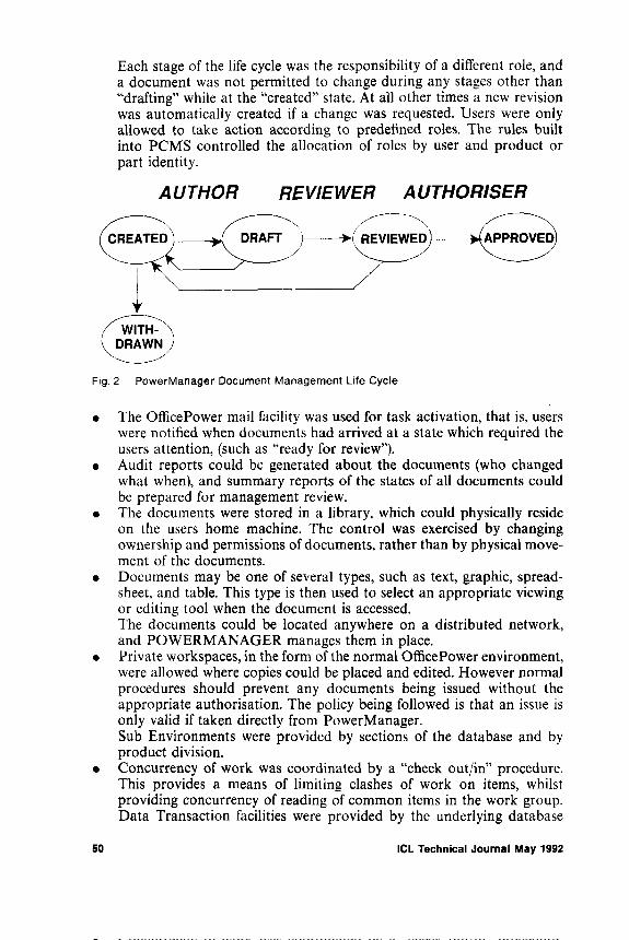
Each stage of the life cycle was the responsibility of a different role, and a document was not permitted to change during any stages other than “drafting” while at the “created” state. At all other times a new revision was automatically created if a change was requested. Users were only allowed to take action according to predefined roles. The rules built into PCMS controlled the allocation of roles by user and product or part identity.
Fig. 2 PowerManager Document Management Life Cycle
• The OfficePower mail facility was used for task activation, that is, users were notified when documents had arrived at a state which required the users attention, (such as “ready for review”).
• Audit reports could be generated about the documents (who changed what when), and summary reports of the states of all documents could be prepared for management review.
• The documents were stored in a library, which could physically reside on the users home machine. The control was exercised by changing ownership and permissions of documents, rather than by physical movement of the documents.
• Documents may be one of several types, such as text, graphic, spreadsheet, and table. This type is then used to select an appropriate viewing or editing tool when the document is accessed.The documents could be located anywhere on a distributed network, and POWERMANAGER manages them in place.
• Private workspaces, in the form of the normal OfficePower environment, were allowed where copies could be placed and edited. However normal procedures should prevent any documents being issued without the appropriate authorisation. The policy being followed is that an issue is only valid if taken directly from PowerManager.Sub Environments were provided by sections of the database and by product division.
• Concurrency of work was coordinated by a “check out/in” procedure. This provides a means of limiting clashes of work on items, whilst providing concurrency of reading of common items in the work group. Data Transaction facilities were provided by the underlying database
50 ICL Technical Journal May 1992
(ORACLE). Normal archiving and backup were provided to preserve the documents.
Thus by performing this experiment we have assessed the many practical problems of the interworking of various tools and users, and the management of centrally held information. One of the most valuable aspects of the experiment was to make all professional staff familiar with the value of managed information, as distinct from the chaos of private files.
7 Summary
We consider that an Engineering Database is a facility of great value to all users, not just programmers. It is novel in that it emphasises the stability of, and relations within, complex information. Early examples have been constructed based on conventional database technology, but the access efficiency of such implementations prevents effective application to small detail.
Appendix A - Description of Data Dictionary
For those readers who have had no contact with a data dictionary this appendix is an outline description of the important parts of the report referred to below.
The basic nature of a proper data dictionary was first captured by the British Computer Society’s Data Dictionary Systems Working Party in [DDSWP, 1972]. The working party recognised that holding the names and definitions for data items was insufficient. Descriptions of the nature and use of each item was needed together with references to the files containing them and the program units using them. This would allow documentation of the implemented system.
They also recognised that documenting the implemented system was in itself insufficient, one also needed to record the results of the analysis exercise carried out before design started, and cross-refer each process and data item to what it reflected in the real world.
The other far-reaching recommendation was that DP should take its own medicine and use single-held data definitions, with cross-references from wherever each definition was used.
The resulting model is usually portrayed in Figure 3.
The diagram is always regarded as documenting the real world above the centre line, and the implemented system below it. Data is documented on the right hand side and the processes on the left. One can thus separate real world processes from implementation processes, and real world data from implementation data. Link capabilities cross quadrant boundaries to document usage (left to right) or traceability (top to bottom).
ICL Technical Journal May 1992 51

Fig. 3 Data Dictionary Quadrants
Having put this into effect it becomes fairly easy and certainly quick to identify which code units have to be changed or recompiled when data items change, and which code units process which transactions.
Most of ICL’s VME Application Development products have recognised the importance of the dictionary by having special means of acquiring their data definitions from the dictionary.
The one big drawback of most existing data dictionaries is their bias towards commercial data processing systems. Anyone planning a new one should be thinking of all types of application as well as system code.
References
BOURNE, T.J. The Data Dictionary System in Analysis and Design. ICL Tech J. 1(3), pp. 292-298 (1979).DDSWP (Data Dictionary Systems Working Party). Report BCS, 1977.LOCKERMANN, P., DITTRICH, K. et al. Database Requirements of Engineering Applications, an analysis. FZI publication no 3, University o f Karlsruhe, July 1985.WARBOYS, B.C. The IPSE 2.5 Project: Process Modelling as the basis for a Support Environment. Proc 1st Int. Conf. on Software Development, Environments, and Factories, Berlin, 1989.
52 ICL Technical Journal May 1992

David Clarke
David H. Clarke is currently Engineering Manager within the System Engineering Unit at ICL Secure Systems at Winnersh. His current responsibilities include the investigation and practical implementation of useable Configuration Management systems within the division for site and project use. The provision of POWER- MANAGER, an installed site Configuration Management service at Winnersh being one instance of this.
An honours graduate (1974) from Imperial College of Science and Technology in Electrical and Electronic Engineering, he has enjoyed a varied design background in a number of Engineering related disciplines at Racal (RF, Modem and Analogue Design), Hoover (Motor Speed Controls and Application of Microprocessors to Domestic Appliances), SIA Ganymede (Warehouse Mobile Crane Control systems and Network Monitoring systems) and International Aeradio (Physical Network Management Systems).
On transfer into ICL he continued to focus on logical and physical network management as Projects Manager of a number of Network and Community Management projects (Systems Management as it now is called) prior to moving to the Development Unit at Winnersh.
Keith Matthews
Keith Matthews graduated in Applied Chemistry from Brighton Polytechnic in 1971 and joined the Ministry of Defence as a PLAN programmer. In 1977 he moved to ICL Dataskil.
The next few years brought a variety of tasks around VME, including writing one of the VME System Structure manuals. In 1983 he helped set up the C&TS Quick- Build consultancy team and spent the next six years supporting Quick Build sales and developments around the world.
He moved to Winnersh in 1989 where he is responsible for Analysis and Design methods and tools policy and developments within ISS. He is a member of the company’s CASE Key Consultants group.
John Pratt
John Pratt is the Engineering Authority of the Systems Engineering unit in ICL Secure Systems. He specifies the architecture of processes, methods and tools to be used in the custom projects managed by ICL Secure systems.
Previously he was the MMI group leader at the European Computer Industry Research Centre, Munich. There he investigated methods of helping users comprehend the complex models embedded in modern interactive systems. These findings were published in the ICL Technical Journal, May 1987.
He graduated in Engineering Sciences at Kings College, Cambridge, and is a Chartered Engineer.
Biographies
ICL Technical Journal May 1992 53
CASE Data Integration:The Emerging International Standards
A. K. ThompsonThe Institute of Software Engineering, 30 Island Street, Belfast. UK
Abstract
T h is p a p e r c o m p a r e s th e t h r e e le a d in g c a n d i d a t e s fo r I n te rn a t io n a l S t a n d a r d in th e a r e a of C o m p u te r A id e d S o f tw a r e E n g in e e r in g (C A S E ) to o l d a t a in te g ra t io n .
It id e n t i f ie s th e m a jo r c o m p o n e n t s r e q u i r e d b y s u c h a s t a n d a r d w h ic h it u s e s to a n a l y s e th e In fo rm a tio n R e s o u r c e D ic tio n a ry S y s te m (IR D S) s t a n d a r d f ro m th e in te r n a t io n a l S t a n d a r d s O r g a n is a t io n (ISO ), th e P o r ta b le C o m m o n T ool E n v iro n m e n t (P C T E ) s t a n d a r d f ro m th e E u r o p e a n C o m p u te r M a n u f a c tu r e r s A s s o c ia t io n (EC M A ) a n d th e C a s e D a ta I n t e r c h a n g e F o rm a t (C D IF) s t a n d a r d f ro m th e U S E le c t ro n ic I n d u s t r i e s A s s o c ia t io n (EIA).
T h e p a p e r c o n c l u d e s t h a t a l th o u g h t h e r e is m a jo r o v e r la p b e tw e e n th e t h r e e c a n d i d a t e s t a n d a r d s t h e r e a r e a l s o s ig n i f ic a n t p o s s ib i l i t ie s fo r c o l l a b o ra t io n a n d c o m m e n ts o n th e c u r r e n t s t a t u s a n d f u tu r e p o s s ib i l i t i e s o f s u c h .
1 Introduction
Professional software development organisations rely heavily on the use of Computer Aided Software Engineering (CASE) tools. Such tools provide vital support to the many techniques used in the development and management of software. These include Information Systems Planning, Structured Analysis and Design, Data Administration, Relational Database Design, Project Management and Configuration Management [Gane, 1989].
The benefits gained by a software development organisation from its set of CASE tools depend on two factors - the individual functionality of each tool and the degree to which the set of tools integrate with one another. The individual functionality of a CASE tool is a competitive matter between the different vendors; the degree of integration is a collaborative matter with scope for standardisation.
54 ICL Technical Journal May 1992
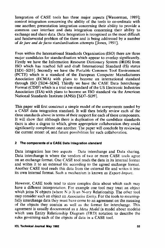
Integration of CASE tools has three major aspects [Wasserman, 1989]; control integration concerning the ability of the tools to co-ordinate with one another; presentation integration concerning their ability to provide a common user interface and data integration concerning their ability to exchange and share data. Data Integration is recognised as the most difficult and fundamental problem of the three and is being addressed by a number of de ju r e and de fa c to standardisation attempts [Jones, 1991].
Even within the International Standards Organisation (ISO) there are three major candidates for standardisation which appear to overlap significantly. Firstly we have the Information Resource Dictionary System (IRDS) from ISO which has reached full and draft International Standard (IS) status [SD1-SD3], Secondly we have the Portable Common Tool Environment (PCTE) which is a standard of the European Computer Manufacturers Association (ECMA) with plans to become an international standard through ISO [SD4-SD6]. Thirdly we have the CASE Data Interchange Format (CDIF) which is a trial-use standard of the US Electronic Industries Association (EIA) with plans to become an ISO standard via the American National Standards Institute (ANSI) [SD7-SD9].
This paper will first construct a simple model of the components needed by a CASE data integration standard. It will then briefly review each of the three standards above in terms of their support for each of these components. It will show that although there is duplication of the candidate standards there is also a degree to which, given appropriate collaboration they could significantly compliment one another. The paper will conclude by reviewing the current extent of, and future possibilities for such collaboration.
2 The components of a CASE Data Integration standard
Data integration has two aspects - Data interchange and Data sharing. Data interchange is where the vendors of two or more CASE tools agree on an exchange format. One CASE tool reads the data in its internal format and writes it to an external file according to the agreed exchange format. Another CASE tool reads this data from the external file and writes it into its own internal format. Such a mechanism is known as E xp o r t-Im p o r t.
However, CASE tools tend to store complex data about which each may have a different interpretation. For example one tool may treat an object which joins N objects (where N ^ 3) an N-ary Relationship. The other tool may consider such an object an A sso c ia tiv e E n tity . For the tools to meaningfully interchange data they must have come to an agreement on the meaning of the objects they contain as well as the format for interchange. This agreement is usually documented as a M e ta M o d e l (a model about models) which uses Entity Relationship Diagram (ERD) notation to describe the rules governing each of the objects of data in a CASE tool.
ICL Technical Journal May 1992 55
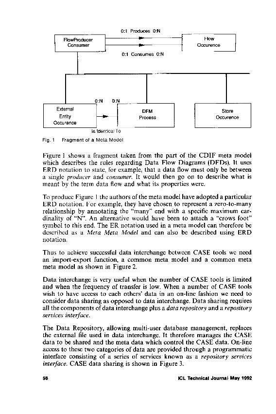
Fig. 1 Fragment of a Meta Model
Figure 1 shows a fragment taken from the part of the CDIF meta model which describes the rules regarding Data Flow Diagrams (DFDs). It uses ERD notation to state, for example, that a data flow must only be between a single producer and consumer. It would then go on to describe what is meant by the term data flow and what its properties were.
To produce Figure 1 the authors of the meta model have adopted a particular ERD notation. For example, they have chosen to represent a zero-to-many relationship by annotating the “many” end with a specific maximum cardinality of “N”. An alternative would have been to attach a “crows foot” symbol to this end. The ER notation used in a meta model can therefore be described as a M eta M eta M odel and can also be described using ERD notation.
Thus to achieve successful data interchange between CASE tools we need an import-export function, a common meta model and a common meta meta model as shown in Figure 2.
Data interchange is very useful when the number of CASE tools is limited and when the frequency of transfer is low. When a number of CASE tools wish to have access to each others’ data in an on-line fashion we need to consider data sharing as opposed to data interchange. Data sharing requires all the components of data interchange plus a data repository and a repository services interface.
The Data Repository, allowing multi-user database management, replaces the external file used in data interchange. It therefore manages the CASE data to be shared and the meta data which control the CASE data. On-line access to these two categories of data are provided through a programmatic interface consisting of a series of services known as a repository services interface. CASE data sharing is shown in Figure 3.
56 ICL Technical Journal May 1992
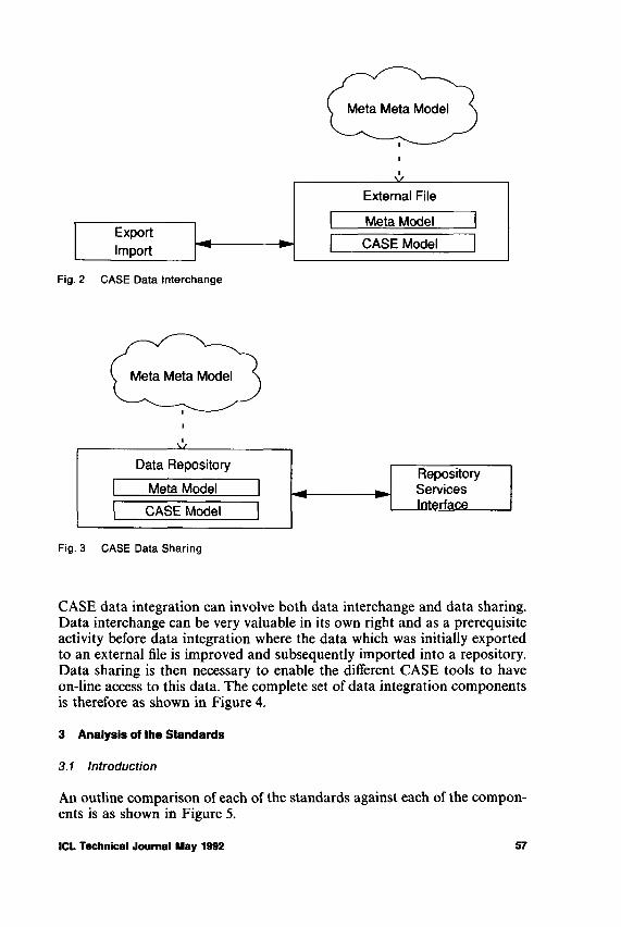
Fig. 3 CASE Data Sharing
CASE data integration can involve both data interchange and data sharing. Data interchange can be very valuable in its own right and as a prerequisite activity before data integration where the data which was initially exported to an external file is improved and subsequently imported into a repository. Data sharing is then necessary to enable the different CASE tools to have on-line access to this data. The complete set of data integration components is therefore as shown in Figure 4.
3 Analysis of the Standards
3.1 Introduction
An outline comparison of each of the standards against each of the components is as shown in Figure 5.
ICL Technical Journal May 1992 57

Fig. 4 CASE Data Integration
CDIF IRDS PCTE
A Meta Meta Model Yes Yes YesA Meta Model ERD/DFD RDBMS Design VendorsAn Import/Export Language Yes No NoA Data Repository No Yes YesA Repository Service Interface No Yes Yes
Fig. 5 Standards v Components
TypicalInstance CDIF IRDS PCTE
OBJECT Meta Meta Fundamental Meta SchemaENTITY Meta IRD Definition Schema Definition Set (SDS)CUSTOMER Model IRD ObjectACME Ltd Application Application (Undefined)
Fig. 6 Names for the 4 data levels
It will be noted immediately that none of the standards offer components necessary to provide all the functions required for CASE data integration. CDIF provides components needed for data interchange whereas IRDS and PCTE provide components for data sharing.
In the previous section we introduced the concept of three different levels of data to be considered by a CASE data integration standard - i.e. CASE model data, meta data and meta meta data. All three standards adopt a “4-level data architecture” as shown in Figure 6. The fourth level is the actual application data which would of course not be integrated. Data at a given level is usually an instance of a type specified as the next higher level. Thus the application data “ACME Ltd” is an instance whose type is at the
58 ICL Technical Journal May 1992
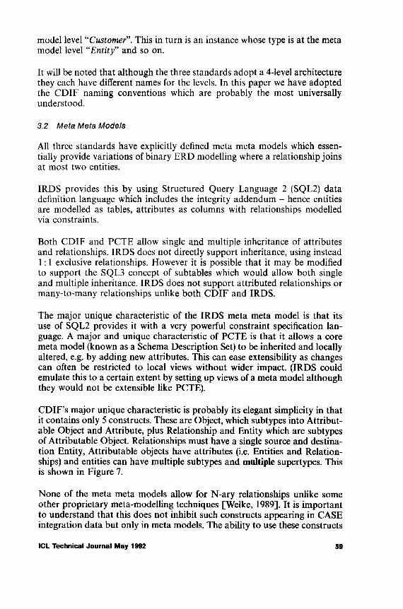
model level “C u sto m er”. This in turn is an instance whose type is at the meta model level “E n ti ty ” and so on.
It will be noted that although the three standards adopt a 4-level architecture they each have different names for the levels. In this paper we have adopted the CDIF naming conventions which are probably the most universally understood.
3 .2 M e ta M e ta M o d e ls
All three standards have explicitly defined meta meta models which essentially provide variations of binary ERD modelling where a relationship joins at most two entities.
IRDS provides this by using Structured Query Language 2 (SQL2) data definition language which includes the integrity addendum - hence entities are modelled as tables, attributes as columns with relationships modelled via constraints.
Both CDIF and PCTE allow single and multiple inheritance of attributes and relationships. IRDS does not directly support inheritance, using instead 1: 1 exclusive relationships. However it is possible that it may be modified to support the SQL3 concept of subtables which would allow both single and multiple inheritance. IRDS does not support attributed relationships or many-to-many relationships unlike both CDIF and IRDS.
The major unique characteristic of the IRDS meta meta model is that its use of SQL2 provides it with a very powerful constraint specification language. A major and unique characteristic of PCTE is that it allows a core meta model (known as a Schema Description Set) to be inherited and locally altered, e.g. by adding new attributes. This can ease extensibility as changes can often be restricted to local views without wider impact. (IRDS could emulate this to a certain extent by setting up views of a meta model although they would not be extensible like PCTE).
CDIF’s major unique characteristic is probably its elegant simplicity in that it contains only 5 constructs. These are Object, which subtypes into Attributable Object and Attribute, plus Relationship and Entity which are subtypes of Attributable Object. Relationships must have a single source and destination Entity, Attributable objects have attributes (i.e. Entities and Relationships) and entities can have multiple subtypes and multiple supertypes. This is shown in Figure 7.
None of the meta meta models allow for N-ary relationships unlike some other proprietary meta-modelling techniques [Welke, 1989], It is important to understand that this does not inhibit such constructs appearing in CASE integration data but only in meta models. The ability to use these constructs
ICL Technical Journal May 1992 59
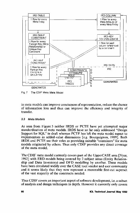
Fig. 7 The CDIF Meta Meta Model
in meta models can improve conciseness of representation, reduce the chance of information loss and thus can improve the efficiency and integrity of transfer.
3 .3 M e t a M o d e ls
As seen from Figure 5 neither IRDS or PCTE have yet attempted major standardisation of meta models. IRDS have so far only addressed “Design Support for SQL” in draft whereas PCTE has left the meta model aspect to implementors as added-value dimensions [e.g. Bourguignon, 1989], Both IRDS and PCTE see their roles as providing suitable “containers” for meta models originated by others. Thus only CDIF provides any direct coverage of the meta model.
The CDIF meta model currently covers part of the UpperCASE area [Vyse, 1992] with ERD models being covered by 2 subject areas (Entity Relationship and Data Inventory) and DFD modelling by another. These models have been circulated widely over the CASE tool vendor and user community and it seems likely that they now represent a reasonable first-cut superset of the vast majority of the constructs needed.
Thus CDIF covers an important aspect of software development, i.e. a subset of analysis and design techniques in depth. However it currently only covers
60 ICL Technical Journal May 1992
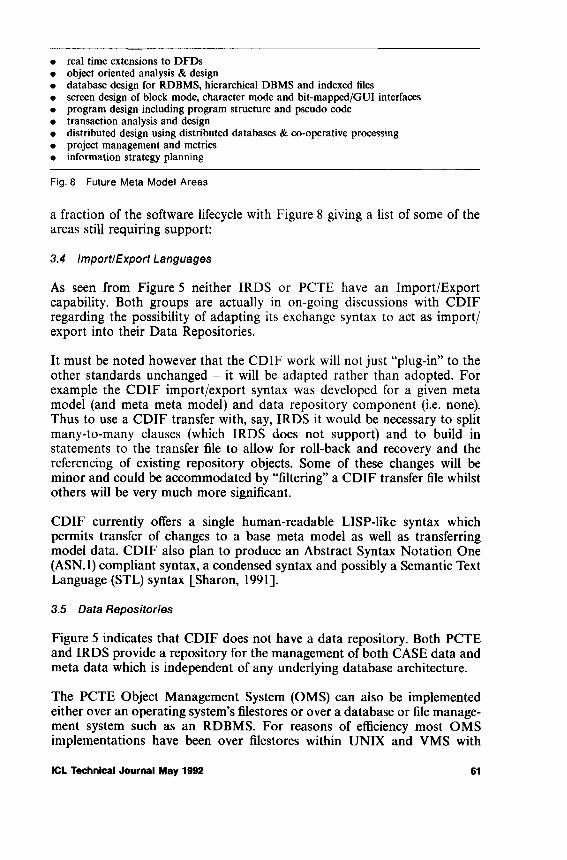
• real time extensions to DFDs• object oriented analysis & design• database design for RDBMS, hierarchical DBMS and indexed files• screen design of block mode, character mode and bit-mapped/GUI interfaces• program design including program structure and pseudo code• transaction analysis and design• distributed design using distributed databases & co-operative processing• project management and metrics• information strategy planning
Fig. 8 Future Meta Model Areas
a fraction of the software lifecycle with Figure 8 giving a list of some of the areas still requiring support:
3 .4 Im p o r t /E x p o r t L a n g u a g e s
As seen from Figure 5 neither IRDS or PCTE have an Import/Export capability. Both groups are actually in on-going discussions with CDIF regarding the possibility of adapting its exchange syntax to act as import/ export into their Data Repositories.
It must be noted however that the CDIF work will not just “plug-in” to the other standards unchanged - it will be adapted rather than adopted. For example the CDIF import/export syntax was developed for a given meta model (and meta meta model) and data repository component (i.e. none). Thus to use a CDIF transfer with, say, IRDS it would be necessary to split many-to-many clauses (which IRDS does not support) and to build in statements to the transfer file to allow for roll-back and recovery and the referencing of existing repository objects. Some of these changes will be minor and could be accommodated by “filtering” a CDIF transfer file whilst others will be very much more significant.
CDIF currently offers a single human-readable LISP-like syntax which permits transfer of changes to a base meta model as well as transferring model data. CDIF also plan to produce an Abstract Syntax Notation One (ASN.l) compliant syntax, a condensed syntax and possibly a Semantic Text Language (STL) syntax [Sharon, 1991],
3 .5 D a ta R e p o s ito r ie s
Figure 5 indicates that CDIF does not have a data repository. Both PCTE and IRDS provide a repository for the management of both CASE data and meta data which is independent of any underlying database architecture.
The PCTE Object Management System (OMS) can also be implemented either over an operating system’s filestores or over a database or file management system such as an RDBMS. For reasons of efficiency most OMS implementations have been over filestores within UNIX and VMS with
ICL Technical Journal May 1992 61

replacement o f the hierarchical structure with a network of bidirectional links. The file contents are then used for storing fine-grain data and the file attributes are generalised to give further inform ation about the objects.
Storage of fine-grain objects as file contents gives rise to problems, as standardisation of file contents is outside the scope of PCTE. This has led to it having to be addressed as an added-value activity by PCTE tool builders like IPSYS w ho have im plem ented a two-tier structure with a com m on services interface to handle fine-grain data effectively.
As stated IRDS does not assume a data repository built around a relational database. To illustrate how it would store its data and m eta data it is simplest however to assum e a relational im plem entation (Figure 9). At the meta m odel level (known as the IR D definition level in IRDS) if we were m odelling the storage of data in a CASE tool supporting ER D we would have objects such as “entity”, “role” and “attribute”. In IR D S these would be represented as rows in table IRD_TABLE. Their attributes would be held as a rows of IR D _C O L U M N and their relationships and keys held as rows in IR D _TA BL E_C O N STR A IN T and IR D _R E F _C O N ST R A IN T andIR D _K E Y _C O L U M N _U SA G E .
Fig. 9 IRDS Relational Example
The tables at the IR D D efinition level are used to generate the tables at the CASE m odel level (known as the IR D level in IRDS): •
• For every row in IRD_TABLE a table is created in the IR D with the name given by the N am e colum n in IRD_TABLE.
62 ICL Technical Journal May 1992
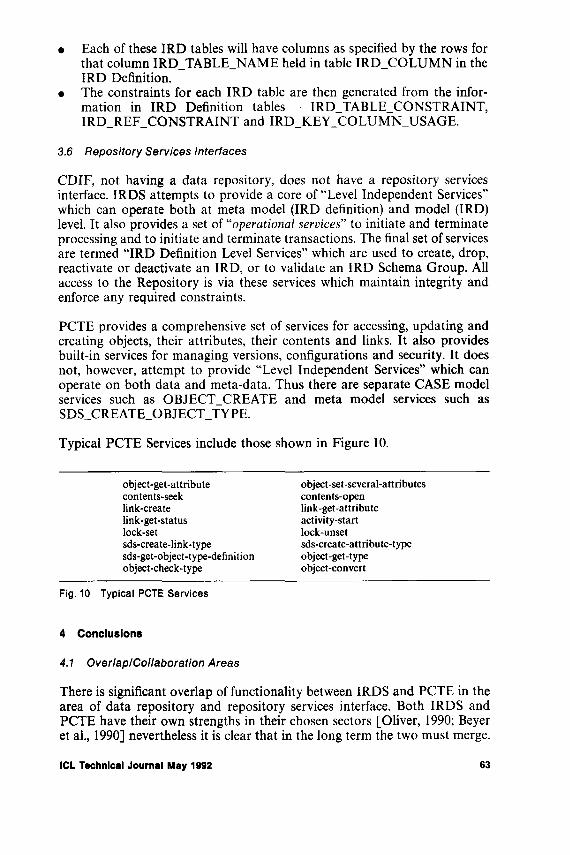
• Each of these IRD tables will have columns as specified by the rows for that column IRD_TABLE_NAME held in table IRD_COLUMN in the IRD Definition.
• The constraints for each IRD table are then generated from the information in IRD Definition tables - IRD_TABLE_CONSTRAINT, IRD_REF_CONSTRAINT and IRD_KEY_COLUMN_USAGE.
3 .6 R e p o s ito r y S e r v ic e s In te r fa c e s
CDIF, not having a data repository, does not have a repository services interface. IRDS attempts to provide a core of “Level Independent Services” which can operate both at meta model (IRD definition) and model (IRD) level. It also provides a set of “opera tiona l services” to initiate and terminate processing and to initiate and terminate transactions. The final set of services are termed “IRD Definition Level Services” which are used to create, drop, reactivate or deactivate an IRD, or to validate an IRD Schema Group. All access to the Repository is via these services which maintain integrity and enforce any required constraints.
PCTE provides a comprehensive set of services for accessing, updating and creating objects, their attributes, their contents and links. It also provides built-in services for managing versions, configurations and security. It does not, however, attempt to provide “Level Independent Services” which can operate on both data and meta-data. Thus there are separate CASE model services such as OBJECT_CREATE and meta model services such as SDS_CREATE_OBJECT_TYPE.
Typical PCTE Services include those shown in Figure 10.
object-get-attribute object-set-several-attributescontents-seek contents-openlink-create link-get-attributelink-get-status activity-startlock-set lock-unsetsds-create-link-type sds-create-attribute-typesds-get-object-type-definition object-get-typeobject-check-type object-convert
Fig. 10 Typical PCTE Services
4 Conclusions
4 .1 O v e r la p /C o l la b o r a t io n A r e a s
There is significant overlap of functionality between IRDS and PCTE in the area of data repository and repository services interface. Both IRDS and PCTE have their own strengths in their chosen sectors [Oliver, 1990; Beyer et al., 1990] nevertheless it is clear that in the long term the two must merge.
ICL Technical Journal May 1992 63
It would be good if such a merger were able to build on the strong points of both efforts - an interesting example of what might be possible is given in [Altomare et al., 1989] which describes how a prototype IRDS services interface was built on top of a PCTE repository.
Collaboration possibilities focus on the use of CDIF as a gateway into IRDS or PCTE and the incorporation of CDIFs meta models into an IRDS or PCTE repository. Bi-lateral discussions are currently underway between CDIF and PCTE and CDIF and IRDS to this end. It should be noted that CDIF does have a competitor in the Institute of Electrical and Electronic Engineers (IEEE) Task Force on Professional Software Engineering Tools who are also developing a meta model and import/export format [Sharon, 1991],
Historically there has been a major difference of technical opinion between ISO and ANSI on IRDS [Holloway, 1988] - to the extent that there is a separate ANSI IRDS standard. It is likely, however, that in the next 3-5 years we shall see considerable convergence between ISO and ANSI in the form of an IRDS2 standard. This is likely to be based on the current ISO work given a heavily object oriented flavour based on “A Tools Integrating Standard” (ATIS) which is being proposed for ANSI under X3H6 by CASE Integration Services (CIS) committee. It remains to be seen how easily the good aspects of both efforts can be merged without one consuming the other. Perhaps IRDS2 may also form the vehicle for PCTE to IRDS convergence?
4 .2 In te r c e p t S tr a te g y
Given that data interchange is a prerequisite for data sharing it is clearly too early for a software development organisation to achieve data integration around the international standards candidates.
CDIF is likely to provide a commercial data interchange facility by mid 1992 - but only for the UpperCASE techniques of ERD and DFD. It would seem therefore that there are two further milestones on the road to open data integration. Firstly, as identified earlier, CDIF must have become a gateway into either PCTE or IRDS. Secondly the CDIF meta model needs to evolve to cover some of the areas identified in Figure 8.
Of particular importance are the techniques which bridge from analysis into logical and physical design such as pseudo-code and database design - without support for these there are no possibilities for automated generation of applications, which is a major attraction to most CASE users. Support by the meta model for project management and configuration management is also needed to support controlled sharing of CASE data.
A credible strategy for a software development organisation may be to use CDIF now for UpperCASE data interchange to gain familiarity with the
64 ICL Technical Journal May 1992

process and problems. In doing this it is likely that they will find serious problems of a data administration nature. They can start to resolve these problems in time for intercepting an open data repository with adequate meta model coverage in 2-3 years time.
Acknowledgements
Thanks are due to DGXIII of the Commission of the European Communities who funded the exploratory action (ESPRIT project 25319.1/IPS) which provided the basic research for this paper.
A detailed report describing the results of the project is available from the Institute of Software Engineering.
References
ALTOMARE et al. A Prototype for the Integration of Information Resource Dictionary System and PCTE. Computer Standards and Interfaces, 1989.
BEYER, H. et al. A Comparative Analysis of Repository Approaches. ISO Working Paper, 1990.
BOURGUIGNON, J. The EAST Eureka Project. Software Engineering Environments -Research and Practice, 1989.
GANE, C. CASE - Methodologies, Products and Future. Prentice-Hall, 1989.HOLLOWAY, S. The Future of Data Dictionaries. BCS, 1988.JONES, R. From Databases to Repositories. The Software Development Monitor, April 1991. OLIVER, H. An Initial Study of IRDS and PCTE. Hewlett-Packard, 1990.SHARON, D. CASE Standards: Is Anyone Listening. CASE Trends, 1991.VYSE, P.J. Defining CASE Requirements, ICL Tech. J. 8(1) p. 3, 1992.WASSERMAN, A. The Architecture of CASE Environments. CASE OUTLOOK, 1989. WELKE, D. The CASE/Reverse Engineering Repository. Meta Systems, 1989.
Standards Publications
SD1 Information Technology - Information Resource Dictionary System (IRDS) Framework (/SO/1 EC 10027:1990(E), International Standard)
SD2 Information Resource Dictionary System (IRDS) Services Interface (ISO/DIS 10728, Draft International Standard)
SD3 Information Resource Dictionary System (IRDS) Design Support for SQL (I SO 11 EC N1046R, Pre-voting Draft)
SD4 PCTE Abstract Specification (Standard E C M A -149, December 1990)SD5 PCTE C Language Binding (Standard E C M A -158, June 1991)SD6 PCTE ADA Language Binding (Standard E C M A -162, December 1991)SD7 CDIF - Framework for Modeling and Extensibility (EIA/IS-81, July 1991) SD8 CDIF - Transfer Format Definition (EIA/IS-82, July 1991)
Part 1: General Rules for CDIF Syntaxes and Encoding Part 2: CDIF Transfer Format Syntax - SYNTAX.l Part 3: CDIF Transfer Format Encoding - ENCODING.l
SD9 CDIF - Standardized CASE Interchange Meta-model (EIA/IS-83, July 1991) Part 1: Semantic Model Part 2: Presentation Model
ICL Technical Journal May 1992 65

Biography
Kenneth Thompson
Kenneth Thompson is Research and Consultancy Manager with The Institute of Software Engineering - an independent research and technology transfer group specialising in CASE Tools and Methods, Software Process Maturity, CASE Integration, Object Orientation and Reverse Engineering.
He was previously Systems Manager with Reuters for UK, Scandanavia and Ireland. Prior to this he worked for a UNIX software house in London writing database and telecommunications applications. His first job after graduating from Queens University Belfast, with a first class honours degree in physics and applied mathematics, was with ICL where he worked for 5 years on small systems applications for System Ten, 1500, System 25, DRS, ME29, OPD and PCs.
At the Institute he has authored major reports on CASE and improving software process quality and has been involved in the CASE Integration area for the last 3 years.
66 ICL Technical Journal May 1992

Building Maintainable Knowledge Based Systems
Frans Coenen and Trevor Bench-CaponLiverpool University, Department of Computer Science
Abstract
F o r th e p r a c t ic a l u s e o f K B S 5 th g e n e r a t i o n s y s t e m s to b e c o m e w id e s p r e a d in th e 1 9 9 0 s s o u n d s o f tw a r e e n g in e e r in g p r in c ip le s n e e d to b e fo llo w e d . O n e im p o r ta n t a s p e c t o f t h i s is m a in ta in a b i l i ty .In th is p a p e r s o m e of th e r e s u l t s o f th e M a in te n a n c e A s s i s t a n c e fo r K n o w le d g e E n g in e e r s (M A KE) p r o je c t w h ic h is n e a r in g c o m p le tio n a r e d e s c r ib e d . T h e a im of t h e p r o je c t is to a d d r e s s t h e im p o r ta n t r o le o f m a in t e n a n c e in K B S s a n d in p a r t i c u l a r K B S s b a s e d o n w r i t te n s o u r c e s of w h ic h le g a l a n d q u a s i - le g a l s y s t e m s p r o v id e th e p r im e e x a m p le . T h e s e s y s t e m s c a n b e v ie w e d a t s e v e r a l d i f f e r e n t le v e ls , th e s o u r c e le v e l , t h e k n o w le d g e r e p r e s e n t a t i o n le v e l a n d th e t a r g e t e x e c u ta b l e r e p r e s e n t a t i o n le v e l . It is s u g g e s t e d th a t th e k e y to th e m a i n t e n a n c e o f s u c h s y s t e m s is to m a in ta in t h e in te r m e d ia te k n o w le d g e r e p r e s e n t a t i o n r a t h e r t h a n p a tc h in g t h e c o d e u s e d in t h e t a r g e t e x e c u ta b l e r e p r e s e n t a t i o n . M a in te n a n c e is t h u s a m a t t e r o f k n o w le d g e r e p r e s e n t a t i o n r a th e r t h a n p r o g r a m m in g .F u r th e r m a in t e n a n c e c a n b e g r e a t ly e n h a n c e d b y u s in g a s u i t a b l e d e v e lo p m e n t e n v i r o n m e n t a n d m e th o d o lo g y s u p p o r t e d b y a s e t o f m a in t e n a n c e to o ls t h a t f o c u s e s o n th i s i n te r m e d ia t e r e p r e s e n t a t i o n a n d i ts r e la t io n to t h e s o u r c e s to i n c r e a s e u n d e r s t a n d a b i l i ty a n d h e n c e a d a p ta b i l i ty .
O n e s u c h e n v ir o n m e n t , t h e M A K E A u th o r in g a n d D e v e lo p m e n t E n v i r o n m e n t (M A D E), is d e s c r i b e d in th is p a p e r . T h is h a s b e e n d e v e lo p e d a s p a r t o f t h e M A K E p r o j e c t a n d is d e s i g n e d to e n c o u r a g e th e p r o d u c t io n o f s y s t e m s w h ic h c a n b e m a in ta in e d th r o u g h a n in te r m e d ia t e r e p r e s e n t a t i o n . M A D E is s u p p o r t e d b y a s u i t e o f m a in t e n a n c e to o ls a im e d a t in c r e a s in g u n d e r s t a n d a b i l i ty o f th e in te r m e d ia t e r e p r e s e n t a t i o n a n d to c a r r y o u t v a r io u s v a lid a tio n , v e r if ic a t io n a n d h o u s e k e e p in g t a s k s to e n h a n c e m a in ta in a b i l i ty .T h e M AKE s u i t e o f m a in t e n a n c e to o ls a r e a l s o d e s c r i b e d .
B o th th e M ADE e n v i r o n m e n t a n d m e th o d o lo g y a n d to o ls h a v e b e e n u s e d to p r o d u c e a p ilo t K B S fo r B r itish C o a l 's I n s u r a n c e a n d P e n s io n s D iv is io n . T h is is s ti ll u n d e r g o in g f u r th e r d e v e lo p m e n t b u t s o m e e n c o u r a g in g r e s u l t s h a v e b e e n r e c e iv e d in d ic a tin g t h a t a s o u n d fo o tin g h a s b e e n e s t a b l i s h e d fo r f u r th e r w o rk .
ICL Technical Journal May 1992 67

Although Knowledge Based Systems (KBS) have been with us for some time their use in practice is still limited. One reason for this is that there is a lack of good software engineering techniques to give confidence in such systems. A fundamental aspect associated with these issues is maintainability since poor software engineering typically results in unmaintainable systems. Coping with change is of course a problem associated with all software systems. However this is much more so the case in KBSs than the traditional data processing type software system. This is because, by definition, KBSs are based on knowledge associated with a particular domain. By nature this knowledge is dynamic and hence subject to constant refinement, revision and updating. In particular KBSs based on regulations, which is a field where there is an evident demand for KBS support [Duffin, 1988], are especially subject to change. If we consider a regulation based KBS currently under development for British Coal’s (BC’s) Insurance and Pensions Division as part of the Maintenance Assistance for Knowledge Engineers (MAKE) project BC claim that each year the legal source material on which the system is based will be subject to the following changes:
• Between 10 and 20 court judgements in British Coal cases affecting the law itself,
• Another 5 significant court judgements relating to other employers, but with significance for British Coal.
• Up to 20 new relevant Statutory Instruments.• 10 technical instructions issued by the BC corporation itself.
In addition the policy of British Coal is modified from time to time, and some 10-15 such policy decisions are made in a typical year. Other changes arise from changes in medical views, for example the acceptance that a particular substance can cause dermatitis; policy changes by other bodies, as when a particular firm of solicitors may start to issue writs if the claim is not settled in a certain period of time; and changes in the perception of methods of work of occupations. BC estimate that these will require another 30 changes per year. All of these alterations add up to an average of two changes per week. Although some of these changes may in fact be very minor, the overall result on the BC application, if it is not readily maintainable, will be that it will be out of date even before it is delivered to the end users.
This illustrates the importance of addressing maintenance issues if KBSs are to become more acceptable. In the field of regulation based KBSs this has also been acknowledged by other authors, for example [Bratley et al., 1991], It is our belief that maintenance and related software engineering issues such as validation and verification will not only dominate the development of regulation based KBS throughout the 1990s but the development of AI and KBS systems in general. In this paper some of the results arrived at during the course of the MAKE project, which is now nearing completion, are
1 Introduction
68 ICL Technical Journal May 1992

described. The aim of the project is to investigate the maintenance issues associated with regulation based KBSs. However the resuts will be of interest to all KBS practitioners and have an important bearing on the AI community as a whole. The project is a collaboration between Liverpool Univeristy, ICL Manchester and British Coal. Broadly speaking it can be said to have three distinct branches.
• The BC application.• The MAKE Authoring and Development Environment (MADE).• A suite of associated software tools.
The BC application is a fairly standard regulation based KBS which merits very little discussion. However a brief description of regulation based KBSs in general and the BC application in particular is offered in section 2. With respect to the project the intention was to build a genuine, and realistically sized, application on which the methodology and tools could be tested. The MADE development environment and methodology and the associated tools are the major focus of the project and are the subject of the rest of the paper. The philosophy behind MADE and the tools is that maintainable systems must be built in a maintainable way, and for KBS that maintenance should be carried out on an intermediate representation of the domain knowledge and not by patching the code in the target executable representation. What is distinctive about KBS is that they are built by representing knowledge rather than programming and therefore it is the maintenance of the represented knowledge that we should be addressing and not the code. This will significantly impact on the tools required. This is facilitated by the MADE environment and methodology. KBSs built using MADE can thus be viewed at three different levels, the source level, the intermediate knowledge representation level and the fine grain target executable representation level [Coenen and Bench-Capon, 1991a]. The MAKE suite of maintenance tools are thus aimed at this three level view and are principally designed to increase understandability and hence adaptability of KBSs built using MADE. The tools are also designed to carry out certain validation, verification and house keeping tasks.
2 Regulation Based KBSs
Regulation based KBS, as the name suggests, are KBSs which operate in regulation based domains. The most obvious examples are legal domains which are governed by acts of parliament, statutory instruments and/or court cases. However the field can be extended to any other domains that operate using written regulations and rules, for example codes of practice produced by companies or national and international organisations, such as internal corporate pension schemes, since the nature of the reasoning involved is essentially the same. It should also be noted that many sets of regulations of this type also have some legal bearing so the term legal KBSs may also be applicable to this type of system although the term regulation based KBS is used here.
ICL Technical Journal May 1992 69

Regulation based KBSs were popularised by work carried out at Imperial College, London, on the British Nationality Act system [Sergot et al., 1986] and the Supplementary Benefit system [Bench-Capon et al., 1987], Although neither of these systems was ever used in practice the results of the research carried out were significant and provided the impetus for further research which resulted in a number of operational systems. Perhaps two of the most notable examples of operational regulation based KBSs are the Retirement Pension Forecast and Advice System (RPFA) [Spirgel-Sinclair, 1988] and the VATIA system [Susskind, 1988], Today regulation based KBSs are fairly commonplace, although their practical exploitation represents only a small fraction of the potential demand. This potential will not, we believe, be realised until the maintenance issues associated with these system can be satisfied.
The BC system provides decision support for the processing of industrial injury-related claims by BC employees. These claims are both varied and complex. The most common types of claim are related to either (a) slipping and tripping, (b) roof falls or (c) haulage. Notification of a claim will be received from the applicant’s union or solicitors. A Claims Inspector is then sent out to interview witnesses and officials and collect related evidence. A report is returned to the insurance and pensions division which will include some recommendations as to liability and percentage fault. In most cases BC will then make an offer to the applicant based on the degree of responsibility for the accident which they are willing to accept. Currently processing these claims may take anything between 6 months to 6 years depending on the nature of the claim and requires a considerable amount of expertise acquired through years of experience and legal knowledge. Further, the processing is implemented with no computer support other than for some administrative tasks. The lack of computer support led BC to invest in a number of projects to provide them with the necessary assistance, one of which was the MAKE project.
The BC system is designed to streamline the claims process, improve consistency and provide support for less experienced claims officers. Currently the system is designed to confirm whether BC is liable or not: no degree or quantum of damages is established. The user is presented with a hierarchy of forms to be completed using information obtained by the Claims Inspectors. Some questions must be filled in before allowing the user to proceed, other questions may be left and returned to at a later data. This process continues until the system is able to establish whether BC is liable or not. If necessary the user can refer to the regulations themselves through a system of links between the questions and the relevant sections in the source material. Further, images of various pieces of coal cutting and transporting machinery can be referred to. Any number of cases, limited only by storage space, can be worked on at any one time, each case having its own file. The system is currently undergoing trials at BC’s Insurance and Pension Division’s Sheffield headquarters where it has been well received.
70 ICL Technical Journal May 1992

A fundamental tenet of building any maintainable software system is that well defined development techniques and methodologies must be followed. These usually consist of a step by step, stage-based life cycle which enforces a rigid discipline on the developers and provides a series of review points. The use of a common methodology means that several software engineers can work on a system at different times and still understand the system. For traditional software systems it is suggested that understandability, coupled with adaptability, is the key to maintainability. If a system can be readily understood (given familiarity with the methodology used) it can be more easily adapted and hence the scale of any future maintenance task considerably reduced. This is especially the case, as it often is, where maintenance is carried out by maintenance engineers who were not part of the original development team. By “understandability” we mean not only the comprehensibility of the code but also the ability to identify why it has been included and the justification for it. Further, conventional software engineering suggests that the task is eased if the structure of the program is related to the structure of the problem.
For traditional software systems many development techniques and methodologies exist. Examples include SSADM [Structured System Analysis and Design Methodology] [Cutts, 1991], JSP [Jackson Structured Programming] [Jackson, 1983] and DSSD [Data Structured System Development] [Orr, 1977], Individual corporations and software houses tend to adopt a particular methodology suitable to their needs. For example the UK civil service has adopted SSADM as their standard.
However, these traditional software development methodologies are not readily suited to KBS development, where development tends to be cyclic and where there is typically no clear notion of system requirements or a specification: nor can such systems ever be said to be complete. Further, the operation of such systems is such that “tinkering” with the code can have widespread effects on the logic of the rest of the systems. This is often not the case where the traditional, data processing, type of system is under consideration. A number of development shells, toolkits and methodologies have thus been produced specifically directed at KBS development. Perhaps the best known methodology is KADS [Wielinga, 1986 and Hickman, 1989], Other KBS development environments include CRYSTAL, NEXPERT, KEATS, KEE, and LEONARDO. These methodologies and environments tend to focus on the knowledge acquisition and representation stages of KBS development; maintainability is not a fundamental aim, although it has been argued that if the acquisition and representation stages are carried out correctly this will ease the maintenance task.
The MADE environment described here is specifically designed to produce maintainable systems. The MADE life cycle is shown in Figure 1. The developer starts with a number of source documents that have been suitably
3 The MAKE Authoring and Development Methodology (MADE)
ICL Technical Journal May 1992 71

Fig. 2 Freestyle KANT Structure
prepared. Knowledge analysis then takes place using an analysis tool called KANT (Knowledge engineers ANalysis Tool) (Storrs, 1989). This is a hypertext like tool that allows the user to search the documents for key words and cut and paste relevant sections into a hierarchy of nodes referred to as KANT structures. An example of a set of KANT structures is given in Figure 2. This shows a section of legal text taken from the Mines and Quarries Act 1954 which was used during the development of the BC application. It has been copied into a KANT structure file. The hierarchy consists of a top level node, the root node, from which branch child nodes. Each child node can have siblings and further child nodes ending in a set of leaf nodes. In its simplest form each node can have some plain language text attached to it. In this case the structures are referred to as freestyle KANT structures. Nodes can be folded into parent nodes or unfolded to reveal child nodes. In this respect the following notation is used:
72 ICL Technical Journal May 1992
Fig. 1 The MADE Life Cycle
+ A node which has been unfolded, i.e. its children are visible.— A node that has been folded, i.e. its children are hidden.O A leaf node, i.e. a node that has no children.
The methodology suggests that development commences by identifying tests on objects so as to discover the ontology and vocabulary of the domain from a problem-oriented perspective. Objects can be identified by searching for nouns in the sections of source material of interest. Whether a test is relevant or not depends on what the task, to be supported by the KBS, is intended to establish and the grain size considered appropriate. In the case of the BC application the task supported was to establish whether BC was liable or not. With respect to grain size it may be adequate, for example, to consider the buildings and structures on the surface of a mine in the sample piece of legislation given in Figure 2 to be one and the same object. Alternatively, if a test exists which applies to structures only, buildings and structures will have to be considered as two distinct objects. The relevant tests, when identified, are again stored in a freestyle KANT structure. This is a KANT structure which can have any type or amount of text attached to it as desired by the author.
The next stage in the analysis is to identify, from the tests on objects, Entity Attribute Value triples (EAVs) and store these in another freestyle KANT Structure file. A typical triple would be:
building/structure keptlnSafeCondition true/false
Thus the entity is building/structure, the attribute is keptlnSafeCondition and the possible values which this attribute can take are true or false.
From the EAV structure an object base or class hierarchy determining the vocabulary of the system, a rule base relating these triples and a hierarchy of forms representing the task are constructed in an intermediate representation called MIR (Make Intermediate Representation) which has a formal, but flexible and easy-to-understand syntax. This is the intermediate representation on which it is proposed that all maintenance be carried out. MIR can be defined as a simple language to describe objects and rules. In many respects it has similarities with a typed first order predicate logic with some extensions, for example to handle arithmetic. The class hierarchy and rule base in MIR are stored in a number of formal KANT structures referred to as MIR KANT structures which are then compiled into the target executable representation. Currently this is in a language called Compiled MIR (CMIR) but could equally well be any other target executable representation such as used in KAPPA or NEXPERT. Examples of a section of the class hierarchy and rule base in MIR taken from the BC application are given in Figures 3 and 4. The “O” symbol simply indicates a field break. The similarity with first order predicate logic is evident from Figure 4.
ICL Technical Journal May 1992 73
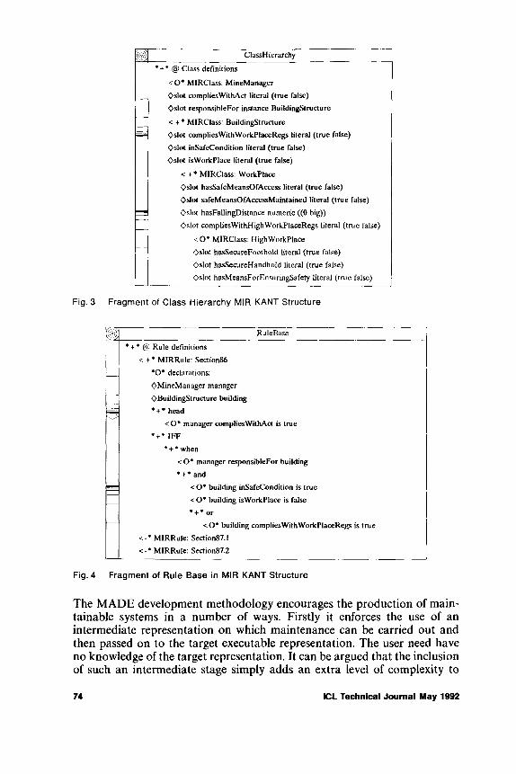
Fig. 4 Fragment of Rule Base in MIR KANT Structure
The MADE development methodology encourages the production of maintainable systems in a number of ways. Firstly it enforces the use of an intermediate representation on which maintenance can be carried out and then passed on to the target executable representation. The user need have no knowledge of the target representation. It can be argued that the inclusion of such an intermediate stage simply adds an extra level of complexity to
74 ICL Technical Journal May 1992
Fig. 3 Fragment of Class Hierarchy MIR KANT Structure
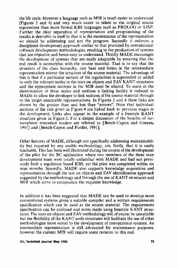
the life cycle. However a language such as MIR is much easier to understand (Figures 3 and 4) and very much easier to relate to the original source expressions than more formal KBS languages such as PROLOG or LISP. Further the clear separation of representation and programming of the results is desirable in itself in that it is the maintenance of the representation we should be addressing and not the program. Secondly it enforces a disciplined development approach similar to that provided by conventional software development methodologies, resulting in the production of systems that are objective and hence easy to understand. Thirdly MADE encourages the development of systems that are easily adaptable by ensuring that the end result is isomorphic with the source material. That is to say that the structure of the class hierarchy, rule base and forms in the intermediate representation mirror the structure of the source material. The advantage of this is that if a particular section of the regulations is superseded or added to only the relevant nodes in the tests on objects and EAV KANT structures and the appropriate sections in the MIR need be altered. To assist in the identification of these nodes and sections a linking facility is induced in MADE to allow the developer to link sections of the source material through to the target executable representations. In Figures 3 and 4 these links are shown by the greater than and less than “arrows”. Note that individual sections of the rule given in Figure 4 are linked back to previous stages in the development. Links also appear in the example of a freestyle KANT structure given in Figure 2. For a deeper discussion of the benefits of isomorphism interested readers are referred to [Bench-Capon and Coenen, 1991] and [Bench-Capon and Forder, 1991],
Other features of MADE, although not specifically addressing maintainability but required by any usable methodology, are, firstly, that it is easily teachable. This has been well illustrated during the course of the development of the pilot for the BC application where two members of the three man development team were totally unfamiliar with MADE and had not previously built a regulation based KBS, yet the pilot was completed within six man months. Secondly, MADE also supports knowledge acquisition and representation through the test on objects and EAV identification approach suggested by the methodology and through the use of KANT structures and MIR which serve to encapsulate the requisite knowledge.
In addition it has been suggested that MADE can be used to develop more conventional systems given a suitable compiler and a written requirements specification which can be used as the source material. The requirements specification can be analysed and notes made using freestyle KANT structures. The tests on objects and EAV methodology will of course be unsuitable but the flexibility of the KANT node structures will facilitate the use of other methodologies more suited to the development of conventional systems. An intermediate representation is still advocated for maintenance purposes, however the current MIR will require some revision to this end.
ICL Technical Journal May 1992 75

The description of MADE given here is necessarily limited. For a fuller discussion interested readers are referred to [Coenen and Bench-Capon (1991b)].
4 The MAKE Suite of Maintenance Tools
From the previous section it can be seen that by using an environment and methodology, such as MADE, that encourages the production of readily maintainable systems using an intermediate representation considerable advantages are gained. Perhaps the most significant advantages are the under- standability and hence the adaptability that derives from the use of the MIR intermediate representation and the isomorphism with the source. Under- standability can be increased if the maintenance engineer is provided with facilities to view the system from the different perspectives. To this end, as part of the MAKE project, a number of maintenance tools have been developed designed to increase understandability. These consist of browsers and graphers which will allow the user to inspect and navigate round the system. Namely:
1 The Class-Instance Browser.2 The Justification Browser.3 The Consequence Browser.4 The Datamap.
Another important aspect of maintenance is preventive maintenance, i.e. validation and verification prior to delivering the system to the end user. In this manner much future corrective maintenance, to use Swanson’s categorisation (Swanson, 1976), can be avoided. Naturally this will not address any future perfective maintenance required by the user or adaptive maintenance resulting from changes in the domain knowledge. These will have to be tackled as and when they arise. However, in due course, validation and verification will also play an important role here. In this paper validation is defined as the process of checking that the system does what the user expects it to do, i.e. the result is correct. Verification is defined as the process of checking that the systems operation is correct, i.e. that the result is arrived at in the correct manner.
To validate a system provision must be made to allow the user to inspect the system during its operation; a suitable tool has therefore been specified:
5 The RuleBase Animation Tool.
Verification of a KBS includes checking for a number of structural defects in the KB, such as the identification of redundant and subsumed rules and checking for hard contradictions and soft inconsistencies. To allow for this identification two verification tools have been specified:
6 The Redundancy ID Tool.7 The Subsumption ID Tool.
76 ICL Technical Journal May 1992
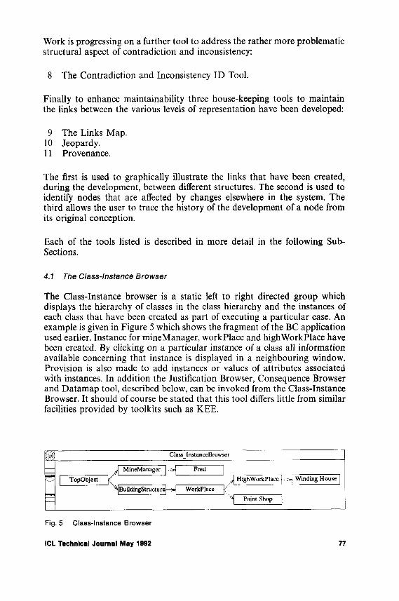
Work is progressing on a further tool to address the rather more problematic structural aspect of contradiction and inconsistency:
8 The Contradiction and Inconsistency ID Tool.
Finally to enhance maintainability three house-keeping tools to maintain the links between the various levels of representation have been developed:
9 The Links Map.10 Jeopardy.11 Provenance.
The first is used to graphically illustrate the links that have been created, during the development, between different structures. The second is used to identify nodes that are affected by changes elsewhere in the system. The third allows the user to trace the history of the development of a node from its original conception.
Each of the tools listed is described in more detail in the following Sub- Sections.
4.1 The Class-Instance Browser
The Class-Instance browser is a static left to right directed group which displays the hierarchy of classes in the class hierarchy and the instances of each class that have been created as part of executing a particular case. An example is given in Figure 5 which shows the fragment of the BC application used earlier. Instance for mineManager, workplace and high Workplace have been created. By clicking on a particular instance of a class all information available concerning that instance is displayed in a neighbouring window. Provision is also made to add instances or values of attributes associated with instances. In addition the Justification Browser, Consequence Browser and Datamap tool, described below, can be invoked from the Class-Instance Browser. It should of course be stated that this tool differs little from similar facilities provided by toolkits such as KEE.
jgjj ClassInstanceBrowser
— MineManager | ■ Fred |<"> | TopObject HighWorkPlace | • - > j Winding House j
^jBuildingStructure|— Workplace ^'I Paint Shop ~j
Fig. 5 Class-Instance Browser
ICL Technical Journal May 1992 77

4 .2 T h e J u s t if ic a t io n B r o w s e r
During execution o f a case the inference engine keeps track of how each object/slot obtained its value. This is done by m aintaining justifications in terms of the rules, user input, or pre-defined sources of values. The justification browser will then allow the m aintenance engineer to exam ine graphically the justification links for any given object/slot. A simplified justification browser is given in Figure 6. It shows how the value for the com plies W ithW orkPlaceRegs slot was arrived at. The justification browser still requires further refinement.
'(<;)/ JustificationBrowser
f it shop/hasSafeMeansOf... |
lint shop/safeMeansQf... j
. shop/hasFailingDistanceTj paint shop/hasSecure... j
int shop/compliesWith... paint shop/hasSecure...
' paint shop/hasMeansFor... /
Fig, 6 Justification Browser
4 .3 T h e C o n s e q u e n c e B r o w s e r
The consequence browser is similar to the justification browser but allows the user to exam ine the consequences of a particular object/slot value. A stylised exam ple o f the consequence browser is given in Figure 7. It shows the result o f an instance o f the type w orkplace for which the value for the attribute hasSafeM eansOfAccess is false, i.e. the result effects the Attribute com pliesW ithAct for the instance fred. Again further work is required so that values are displayed.
§§)]] ConsequenceBrowser
/ paint shop/safeMeansOf... paint shop/compliesWith... | . / frcd/compliesWithAct |
Fig. 7 Consequence Browser
4 .4 T h e D a ta m a p
The D atam ap is another left to right directed graph. The current version shows the relationship between attributes and rules in the rule base. The user can navigate up and down the rule base from the root attribute down to the leaf attributes inspecting any desired attribute or rule e n r o u te . This
78 ICL Technical Journal May 1992

Fig. 9 Representative Datamap showing Propositions and Clauses in CMiR
A second level will be incorporated into the Datamap to allow navigation through the propositions and clauses of the target representation. The significance of this is that the user will be able to switch between the intermediate representation and the fine grain executable representation so as to examine the precise consequences of the knowledge as represented. An example is given in Figure 9. This shows the above two rules in the target executable representation where they will have been translated into a set of clauses of the form:
Clause 1.1: A if B Clause 1.2: A if C
Clause 1.3: not A if not B and not C Clause 2.1: B if D and E
Clause 2.2: not B if not D Clause 2.3: not B if not E
A more detailed description of the Datamap can be found in Coenen and
ICL Technical Journal May 1992 79
Fig. 8 Representative Datamap showing Attributes and Rules in MIR
gives the maintenance engineer a clear visual view of the rules in the knowledge base. An illustration is given in Figure 8 in which a representative Datamap is given depicting two rules of the form:
Rule 1: A iff B or C Rule 2: B iff D and E
Bench-Capon (1991b). Buttoning on a rule node will also permit a view of the source from which the rule was derived.
4 .5 T h e R u le b a s e A n im a t io n T o o l
Part of the validation of a system involves “populating” the knowledge base with suitable test data and then tracing the inferences that can be made. The RuleBase animation tool will allow the maintenance engineer to do this. This tool uses an interface similar to the Datamap but addresses the dynamic aspects of the RuleBase. It allows the user to populate the RuleBase by creating instances and asserting propositions and then determine what inferences can be made as a result. When the behaviour is unexpected, either because an inference is made which should not be made, or because an inference which was expected fails to be made, this tool will enable the user to locate the precise clause which caused the failure, and from this the rule, analysis and source from which it was derived. Such animation is a necessary adjunct to the “by eye” validation supported by the static browsers and graphers described above, since the practical consequences of a given fragment of the KB may be hard to envisage in the abstract. This tool has yet to be implemented although the desired result can be substantially achieved using the Class Browser.
4 .6 R e d u n d a n c y
Redundant rules (sometimes called “dead end” rules) are defined as rules that do not play any part in establishing the root proposition of the application. In other words the head propositions of these rules are not connected in any way to the root proposition which the application is intended to establish. A redundant rule may not affect the operation of the system in any way, in which case their identification will simply be part of a tidying up exercise. However it may be that the head to a redundant rule should have been called from the body of another rule and due to an authoring error it is not. In this case the identification of such a rule is significant. It should also be noted that a redundant rule may have other rules hanging from it in which case the entire group of rules can be said to be redundant.
4 .7 S u b s u m p tio n
A subsumed rule is a rule that adds nothing to the inference process because it is, for example, weaker than another rule. As with redundant rule identification the detection of subsumed rules may only be part of a tidying up exercise. Alternatively it may that the subsumed rule is in error and that the intention was otherwise.
4 .8 H a r d C o n tr a d ic t io n s a n d S o ft In c o n s is te n c ie s
When adding or modifying rules in a KB during a maintenance session a hard contradiction or soft inconsistency may be introduced. In logical terms
80 ICL Technical Journal May 1992
this means that there can be no model for the knowledge base, so the knowledge base cannot be correct. In its simplest form a hard contradiction may be represented by a constraint of the form:
A & not A
Soft inconsistency is a modified phenomenon and occurs when some proposition is a consequence of the KB when it is in fact known that its negation is possible. This means that the knowledge base excludes some models which are known to occur, and again suggests a defect. In the simplest possible case we may have two rules:
fruit (green) = > ripe fruit (green) = > not (ripe)
At first glance there would appear to be some contradiction here as ripe and not ripe cannot both be true. However there is no “logical” contradiction here because both rules can still exist in the KB if the value for fruit is never green. We say that a logical consequence of the KB is:
not fruit (green).
However if we know that fruit can have a value green this would indicate that our KB is in error, i.e. a soft inconsistency exists.
Thus a minimal verification of the knowledge base will involve ensuring that neither of these situations exist. A tool is under development as part of the MAKE project which will allow such contradictions in the knowledge base to be detected.
4 .9 T h e L in k s M a p
During development, as described in section 3, links are created between sources, freestyle KANT structures, MIR KANT structures and the Class Hierarchy and Rule Base in the target executable representation. In the case of the BC application there were a number of source documents which were decomposed into subtopic structures each addressed by different members of the development team. From these a number of tests on objects and EAV structures were produced leading to a number of MIR KANT structures and culminating in the final Rule Base and Class Hierarchy in the target executable representation. In all some forty linked files were created. The Links Map provides a graphical overview of the links between the files indicating the total number of links and the number of links in each direction. The tool has been found to be useful in giving an overview of the systems development and to weed out superfluous structures and groups of structures.
ICL Technical Journal May 1992 81
4 .1 0 J e o p a r d y
An essential tool to enable maintenance when sources change is one which identifies rules derived from a given source fragment. One of the principal aims of the links created during development is the identification of the development trail of a particular proposition in a rule or object slot in the class hierarchy. The links also provide a facility to identify parts of the system that are affected by changes made elsewhere in the system and hence enhance adaptability. For example if a section of source material is altered due to (say) a recent court case the nodes affected by this change can easily be identified.
4 .1 1 P r o v e n a n c e
Another useful tool has been found to be the provenance tool. This allows the maintenance engineer to trace the history of every node in the system. When ever a change is made to a node this is logged and stored. By clicking on the head of a node this history can be retrieved and inspected. This has proved to be particularly useful in the BC application where a number of developers worked on the system. Further it is envisaged that this will also be of use to the eventual maintenance engineers who will not have been part of the original development team.
5 Conclusions
In this paper some of the results to date of the MAKE project have been described. Attention has been focused on the MADE methodology and the suite of maintenance tools developed as part of the project. The advantages gained by using the MADE environment and methodology with respect to maintenance are suggested to be understandability and adaptability. This is attributed to the following:
• The use of an intermediate representation.• The linking facilities incorporated into the methodology.• Isomorphism with the source.• The discipline imposed by the methodology.
The MADE is supported by the maintenance tools described in section 4 and detailed in the accompanying Sub-Sections. These tools then provide the user with the following additional advantages when carrying out maintenance tasks: •
• Increased understandability over that provided by the MADE itself.• Validation.• Verification.• Housekeeping.
82 ICL Technical Journal May 1992

The MADE environment and methodology have been used to develop a pilot system for BC’s pensions and insurance division which is currently undergoing trials at their Sheffield headquarters. The pilot has been well received and is currently undergoing further development. Many of the tools described have been implemented with encouraging results. Those that have not been implemented have been specified and are currently under development.
6 Acknowledgements
The MAKE project is supported by the Information Engineering Directorate of the UK Department of Trade and Industry and the UK Science and Engineering Research Council. The project collaborators are ICL, the University of Liverpool and British Coal. The authors would like to express special thanks to Charlie Portman for his working paper “Authoring in MAKE” and Mick Smith for his working paper “The MAKE Authoring Environment: A Design Proposal”, both of ICL Manchester. Finally it should be noted that the views expressed in this paper are those of the authors and may not necessarily be shared by the other project collaborators.
References
BRATLEY, P., FEMONT, J., MACKAAY, E. and POULIN, D. Coping With Change. Proceedings o f the 3rd International Conference on AI and Law, ACM Press, Oxford, pp. 53-61 1991. BENCH-CAPON, ROBINSON, G O., ROUTEN, T.W. and SERGOT, M.J. LogicProgramming for Large Scale applications in Law: A Formalisation of Supplementary Benefit Legislation. In Proceedings o f the 1st International Conference on AI and Law, Boston, ACM Press, pp. 190-198 1987.BENCH-CAPON, T.J.M. and COENEN, F.P. Exploiting Isomorphism: Development of a KBS to Support British Coal Insurance Claims. In Proceedings o f the 3rd International Conference on A I and Law, Oxford, ACM Press, pp. 62-68 1991.BENCH-CAPON, T.J.M. and FORDER, J.M. Knowledge Representation for Legal Applications. In: Bench-Capon, T.J.M. (ed), Knowledge Based Systems and Legal Applications. Academic Press, pp. 245-264 1991.COENEN, F.P. and BENCH-CAPON, T.J.M. KBS Development Using X windows: The Made Development Methodology. Proceedings o f UKVUG Summer Conference, Liverpool, pp. 64-72 1991.COENEN, F.P. and BENCH-CAPON, T.J.M. A graphical Interactive Tool for KBS Maintenance. In Karagiannis, D. (ed). Database and Expert Systems Applications. Springer-Verlag, pp. 166-171 1991.CUTTS, G. Structured System Analysis and Design Methodology. Blackwell Scientific, 2nd Edition, 1991.DUFFIN, P.H. (ed). Knowledge Based Systems: Applications in Administrative Government. Ellis Horwood, Chichester, UK, 1988.HICKMAN, F. Knowledge Based Systems Analysis: A Pragmatic Introduction to the KADS Methodology. Ellis Horwood, Chichester, UK, 1989.JACKSON, M.A. System development. Prentice Hall, 1983.ORR, K.T. Structured System Development. Yourdon Press, New York, 1977.SERGOT, M.J., SADRI, F„ KOWALSKI, R.A., KRIWACZEK, F„ HAMMOND, P. and CORY, H.T. The British Nationality Act as a Logic Program. Communications ACM, Vol. 29, No. 5, pp. 370-386 1983.SPIRGEL-SINCLAIR, S. and TREVENA, G. The Retirement Pension Forecast and Advice System. In Duffin, P.H., op cit. pp. 34-40 1988.
ICL Technical Journal May 1992 83
STORRS, G.H. and BURTON, C.P. KANT, A Knowledge Analysis Tool. ICL Tech. J., 6(3), pp. 572-581 1989.SUSSKIND, R. and TINDALL, C. VATIA: Ernst and Whinney’s VAT Expert System. Proceedings o f the Fourth International Expert Systems Conference, London, 1988.SWANSON, E.B. The Dimensions of Maintenance. Proc. 2nd International Conference on Software Engineering, IEEE, pp. 492 497 1976.WIELINGA, B.J., BREUKER, J.A. and van SOMEREN, M.W. The KADS System, Functional Description. Esprit Project P1098 Deliverable T 1.1, Department of Social Science Informatics, University of Amsterdam, 1986.
Biographies
Frans Coenen
After eight years service in the Merchant Navy as a Navigating Officer, Frans Coenen went on to gain a First Class Honours Degree in Maritime Studies at Liverpool Polytechnic. From 1986 to 1989 he was employed as a research assistant at Liverpool Polytechnic engaged on a SERC funded research project to develop a navigational KBS for use by the maritime industry. During this period he gained a Doctorate in Computer Science. Currently Frans Coenen is employed as a Research Associate at Liverpool University engaged upon the Maintenance Assistance for Knowledge Engineers (MAKE) project. This is a collaborative research project between ICL, British Coal and the University to develop maintenance tools to support large KBs. His research interests include software maintenance for KBSs, the use of real time Expert Systems in the maritime industry and intelligent interaction with electronic charts.
Trevor Bench-Capon
Trevor Bench-Capon read Philosophy and Economics at St John’s College Oxford, where he also took a D.Phil. He worked for 6 years in the Department of Health and Social Security, in policy and computer branches, before going to Imperial College, London to research into logic programming applied to legislation. He has been a lecturer in Computer Science at the University of Liverpool since 1987, where he has worked extensively on the application of knowledge based systems techniques to the legal domain, and on the use of argument as the basis for the design of interfaces with knowledge based systems. He has published extensively in both of these areas.
84 ICL Technical Journal May 1992

The Architecture of an Open Dictionary
Michael H. KayICL Fellow, Reading, UK
Abstract
T h i s p a p e r d e s c r i b e s h o w t h e t r a d i t i o n a l r o l e o f t h e d a t a d i c t i o n a r y c a n b e s t r e n g t h e n e d a n d c a r r i e d f o r w a r d in to a w o r l d o f o p e n s y s t e m s , d e s p i t e t h e l a c k of a g r e e m e n t o n i n t e r n a t i o n a l s t a n d a r d s . F lex ib i l i ty a n d a d a p t a b i l i t y a r e e s s e n t i a l r e q u i r e m e n t s ; t h e p a p e r s h o w s h o w t h e s e c a n b e a c h i e v e d b y a d o p t i n g a n o b j e c t - o r i e n t e d a r c h i t e c t u r e .
1 Introduction
The data dictionary has had a central role in ICL’s product line for many years [Bourne, 1979]. Expressed simply, it is the database of information needed by the application developers in an enterprise. The aim of a data dictionary is to capture all information of concern to application developers, for the following reasons:
• To help the enterprise get the maximum return on its investment in information, by documenting the way information flows through the enterprise in support of key business processes.
• To ensure that good design information is available when applications need to be enhanced or corrected.
• To enable applications to interwork with each other.• To allow a variety of application development tools to be used without
the costs and risks of duplicating design information.• To enable components of applications to be re-used.• To maintain control over quality.• To improve the service that application developers can offer to informa
tion users.
In recent years the role of the dictionary as a vehicle for integration of third- party CASE tools has become prominent; but this must not allow us to neglect the other important benefits that a well-maintained dictionary brings to an enterprise.
ICL Technical Journal May 1992 85

The benefits of Open Systems are now widely recognised. Application developers expect to be able to mix and match tools from different suppliers, and they expect their choice of tools to be unconstrained by their choice of hardware platforms and networking architecture. ICL’s response to this expectation is OPENfra m e w o rk [Brenner e t al., 1991], an architecture based on open standards and distributed object-oriented computing. The application development element of O P E N fr a m e w o r k is defined in [G.H. Brown, 1991], One of its key components is an open dictionary.
O P E N fr a m e w o r k requires a dictionary that carries forward the strengths of ICL’s existing technology, augmented with new thinking from recent software engineering research, and that makes the technology fully open.
2 Integrating Tools
We distinguish three aspects of tools integration:
• Data integration: Tools need to share data via a common engineering database [Clarke e t al., 1992],
• User interface integration: Tools must present a common look and feel, and must be simultaneously accessible on the desktop. This is achieved by using the user interface standards incorporated in O PEN fra m e w ork [Hutt, 1991],
• Process integration: It must be possible to define application development processes and to initiate tools in accordance with these processes. This can be at any level from a process describing the entire development life-cycle to a simple model of the edit-compile-test loop. Process integration is achieved using technology such as PSS [Warboys, 1989].
In this paper we are concerned primarily with data integration and in particular with dictionary technology; but the other aspects of tools integration are equally important, and the dictionary architecture takes this into account.
In ICL’s current QuickBuild portfolio, the Data Dictionary System (DDS) acts as the integration focus. A measure of user interface and process integration is achieved through the QuickBuild Pathway product; this, however, lacks the extensibility needed in an open environment.
We can state the goals of the Open Dictionary programme as follows:
• to provide a framework for integration of all information relevant to the application developer and the tools he wishes to use, that meets our customers’ requirements and keeps ICL at the leading edge of CASE integration suppliers;
• to protect the value of ICL’s and its customers’ investment in QuickBuild and DDS;
86 ICL Technical Journal May 1992

• to achieve this within an Open Systems policy as defined by OPEN- fra m e w o rk , in particular, through extensibility.
3 Background - Dictionary Systems
The concept of a data dictionary was first mooted in the early 1970’s [see Holloway, 1988] as a way of controlling the data definitions used throughout an enterprise. The concept was developed further by a specialist group of the British Computer Society [BCS, 1977], ICL participated actively in this group and was the first vendor to adopt the concept as a central plank of its data management strategy. By the late 1970’s [Bourne, 1979] the data dictionary was being seen as the “corporate database for the MIS department”, containing all data about data in the enterprise, including definitions of where and how it is processed.
During the 1980’s the emphasis switched from providing an information resource for application developers, to providing an integration mechanism for application development tools. This meant that dictionaries had to become extensible. ICL re-engineered the DDS product to be extensible in the early 1980’s, and the technical decisions made at that time have been a major contributor to the success of QuickBuild since (as a measure of this, the 25 element types supported before extensibility was introduced have grown to around 120 in the latest release, DDS.850).
The architecture of the new DDS was innovative and is still in advance of many of its competitors [Jones, 1991], As the internal architecture has never been fully published, and because much of it carries forward into the Open Dictionary, I describe its salient points in section 4.
The dictionary tradition is far from universal. Geographically, it is stronger in the UK than in the United States (indeed, in the US, the term data dictionary is often used to refer to something much less ambitious, for example the system catalogues of a relational database). Indeed, the term d a ta d ic tio n a ry has become rather a misnomer, and re p o sito ry is becoming increasingly fashionable as a substitute. But because so many ICL customers have been dictionary enthusiasts for many years, we are sticking with the term for the time being.
In other software development cultures, different traditions have developed [Clarke e t a l , 1992]. Within large complex projects, such as those developing aerospace systems or computer operating systems, the focus is on managing the interactions of program modules rather than on data modelling; this led to the development of configuration management and source-code control systems. Meanwhile research on software engineering identified the need for better support of the software development process, which gave birth to the idea of an Integrated Project Support Environment or IPSE [Warboys, 1989].
ICL Technical Journal May 1992 87
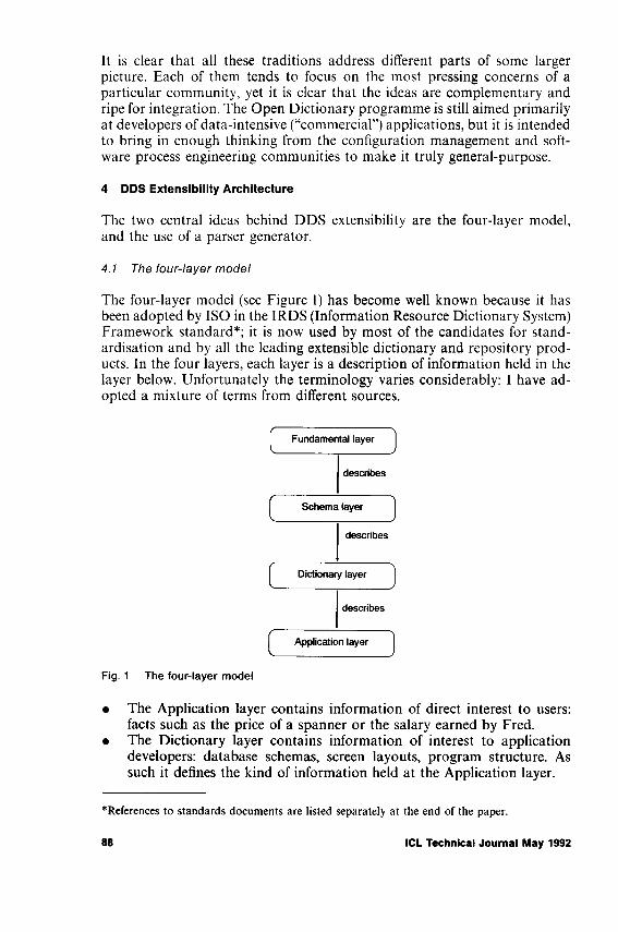
It is clear that all these traditions address different parts of some larger picture. Each of them tends to focus on the most pressing concerns of a particular community, yet it is clear that the ideas are complementary and ripe for integration. The Open Dictionary programme is still aimed primarily at developers of data-intensive (“commercial”) applications, but it is intended to bring in enough thinking from the configuration management and software process engineering communities to make it truly general-purpose.
4 D D S E x te n s ib i l i t y A r c h i t e c t u r e
The two central ideas behind DDS extensibility are the four-layer model, and the use of a parser generator.
4.1 The four-layer model
The four-layer model (see Figure 1) has become well known because it has been adopted by ISO in the IRDS (Information Resource Dictionary System) Framework standard*; it is now used by most of the candidates for standardisation and by all the leading extensible dictionary and repository products. In the four layers, each layer is a description of information held in the layer below. Unfortunately the terminology varies considerably: I have adopted a mixture of terms from different sources.
Fig. 1 The four-layer model
• The Application layer contains information of direct interest to users: facts such as the price of a spanner or the salary earned by Fred.
• The Dictionary layer contains information of interest to application developers: database schemas, screen layouts, program structure. As such it defines the kind of information held at the Application layer.
‘ References to standards documents are listed separately at the end of the paper.
88 ICL Technical Journal May 1992

• The Schema layer defines what kind of information is held at the Dictionary layer: for example, screens, schemas and programs. Information at the schema layer is primarily of interest to tools writers extending the dictionary to accommodate new tools.
• The Fundamental layer defines how Schema-layer information is to be represented; for example using an entity-relationship model or an object model. This layer is primarily of interest to standards bodies and dictionary software vendors. In a given standard or a given dictionary product, the fundamental layer is generally fixed.
In DDS the fundamental layer and the schema layer are completely separated in the internal architecture of the product. The central core of dictionary software understands the fundamental layer but has no knowledge of the schema layer. Extending the schema to incorporate new element types and property types can therefore be done with no software changes.
4 .2 T h e p a r s e r g e n e r a t o r
The second important aspect of DDS extensibility is less well known, namely its use of a parser generator as the mechanism for defining extensions.
Many of the properties supported in DDS have complex syntax. For example, the permitted range of values of an attribute can be expressed in the *VALUE-RANGE property of the ATTRIBUTE elements, whose syntaxfis
'VALUE-RANGE { value [THRU value ] } ...
This syntax defines a convenient way for users to enter and display the information; for example the constraints on a hexadecimal digit can be expressed as
•VALUE-RANGE "0" THRU "9' '"A” THRU “ H"
Such an expression can be mapped easily into the composite data types available in most modern programming languages: the data type of *VALUE-RANGE is a sequence of pairs of values, in which the second of each pair may be null. Mapping this to the type systems of conventional database technology is much more difficult. If we attempted to express the *VALUE-RANGE property in relational third-normal-form, we would require an extra table, with an artificial primary key, and every access to the information would require an expensive join operation.
fCurly braces denote grouping, ellipsis denotes repetition, and square brackets denote an optional clause. Alternatives are separated by a vertical bar. Non-terminal symbols are named in italics. The names of property-types in D D S, for example ‘ VALUE-RANGE, are always signalled with a leading asterisk.
ICL Technical Journal May 1992 89

For really complex properties, such as those encountered when procedural code is stored in the dictionary, the complexity introduced by normalisation would quickly become intolerable. It is largely because the DDS dictionary was required to hold Application Master programs [Brown, Cosh and Gradwell, 1981] that the syntax-based approach was introduced.
A new property type is added to DDS by giving a definition of its syntax in a BNF-like notation called Property Definition Language (or PDL). The parser generator takes this definition and produces as output an Analyser program for dealing with input properties of this type, and a Synthesiser program for re-constituting the property on output. This is shown in Figure 2.
Fig. 2 The DDS parser generator
The full capabilities of DDS Extensibility have never been released outside ICL, largely because the tools are not currently robust enough, but also because the size and relative homogeneity of the VME customer base meant that the benefits of a consistent, centrally-designed schema (the DDS model) appeared to outweigh the advantages of encouraging individual users to go off in different directions. It is clear that in the world of Open Systems, where it is necessary to accommodate far more variety than on VME (for example, at least four relational database management systems), it will not be possible for all the tools integration to be centrally coordinated in the same way.
5 On Being Open
The word open has become the most fashionable adjective in the vocabulary of information technology marketing, so it is tempting for the engineer to dismiss it as technically meaningless. It is indeed used with a variety of meanings, but all of them reflect the fact that enterprises need to construct integrated information systems without relying on a single supplier to deliver all the components of the system.
90 ICL Technical Journal May 1992

OPENfra m e w o rk defines openness in terms of three characteristics:
• conformance with official international standards• adherence to industry norms• extensibility and adaptability: that is, the ability to accomodate variety
and change.
In the dictionary world, it is not possible to achieve openness purely by conformance with one single standard, whether official or unofficial. There are several formal standards under development that are all to some degree incompatible (for example, ISO IRDS, ANSI IRDS, PCTE, and CDIF); there are also powerful industry coalitions around proprietary standards such as AD/Cycle from IBM, Cohesion from Digital, SoftBench from Hewlett-Packard, and indeed around ICL’s own QuickBuild. There is no sign of the tools industry converging towards one single standard.
Even if the tools industry did converge on a standard such as PCTE or IRDS, this would not guarantee interoperability. This is because these standards currently define only the fundamental layer, not the schema layer. Just as an X.400 electronic mail system is of no use without standards for document formats, so a dictionary standard is of no use without schema- layer standards for some of the design objects that are to be exchanged. Such standards will take even longer to converge.
Therefore, the only way of providing the openness our customers need is through extensibility and adaptability.
We must be able to accommodate multiple standards. The key to this is that the dictionary must include powerful capabilities to transform information between different representations. It must be possible to adapt the dictionary to the existing tools, rather than requiring the tools to be adapted to the dictionary. This requirement is at the heart of all the significant architectural decisions described in the following sections.
6 Why Object-Oriented?
We did not set out to design an object-oriented dictionary; we set out to meet user requirements, and discovered (in some cases slowly and painfully) that object-oriented ideas held out the only prospect of a solution.
This section tries to summarise the benefits of adopting an object-oriented approach.
Firstly, virtually all recent research on software engineering environments and on design applications in general has converged on object-oriented thinking [A. W. Brown, 1991], Even if we disliked the approach, it would be unwise to cut ourselves off from the best research thinking by adopting a different view.
ICL Technical Journal May 1992 91

The technical benefits of the object-oriented approach include:
• C o m p le x o b jec t m odelling . The inadequacies of the relational model when applied to complex engineering data are well documented [Stonebraker, 1990]. The syntax-based approach used in DDS gives a partial solution, which is particularly effective in preventing excess complexity at the human interface, but still places considerable burden on writers of tools to analyse data presented across the interface. Object models with a rich type system provide the natural answer.
• Incorp o ra tio n o f ru les and behaviour. We have seen that much of the openness of the dictionary system comes from its ability to transform information into different representations behind the tools interface. This is achieved naturally in an object-oriented system in which data and processing are encapsulated within an object’s interface.
• R e-u se and re finem en t. Experience over a decade of QuickBuild development shows that integration of tools is expensive; one reason for this is that it is very difficult to take advantage of the fact that similar work has already been done by someone else. In an Open Systems context, this is exacerbated by the fact that nearly every technology has several popular varieties. This is true of strategic components such as relational databases and graphical user interfaces, and also of commodities such as editors and C compilers. So the inheritance mechanism of an object- oriented approach, which allows one to write code that defines the differences from something that already exists, has great potential.
• P ers is ten t p rogram m ing . Anyone who has written programs to drive a complex interface such as that offered by the IRDS standards, by PCTE, by IBM’s MVS/Repository, or for that matter by DDS, knows what a tedious business it is to perform the simplest tasks. Procedure call interfaces are a very unwieldy mechanism for accessing databases. Pre- processed sublanguages such as SQL alleviate the problem but are no panacea. The essential problem is the incompatibility of the type systems of the programming language and the database; and the more complex the data, the worse this problem becomes. The answer is a persistent programming environment [Atkinson and Buneman, 1987, Greenwood e t al., 1992] in which computation and data access are handled by a single language with a uniform type system. It is our experience that a persistent programming language for dictionary access can vastly reduce the cost of developing new dictionary-based tools when compared with a conventional application programming interface.
7 Open Dictionary Architecture
This section describes the architecture of the Open Dictionary System.
The top-level decomposition of the system, shown in Figure 3, identifies fivesubject areas. These are:
92 ICL Technical Journal May 1992

• Object-oriented database• Dictionary kernel• Converters• Dictionary editor and browser• Schema and internal tools
Each of these subject areas is constructed as a set of object classes defining specific behaviour. The objects invoke each other using a common request mechanism. This mechanism is initially provided by the object-oriented database, but in the longer term it equates to the Object Request Broker defined by the Object Management Group.
Tools access the dictionary using this request mechanism; they may either access the database directly, or access converters that present the information in the form they expect it. A common user interface to the dictionary editor/ browser and to interactive tools is provided by standard graphical user interfaces such as Motif or Open Look.
Note the distinction between internal and external tools. Internal tools are implemented as methods within the database, and can therefore be invoked from within the system. External tools are implemented as applications using the database; these can only be invoked through the user interface.
7.1 O b je c t -O r ie n t e d D a ta b a s e
The Raleigh object-oriented database has been described in a previous paper [Kay and Rivett, 1991]. It is being developed to underpin both the Open
Fig. 3 Dictionary Architecture
ICL Technical Journal May 1992 93
Dictionary and the Open System Management Information Base [Gale, 1991], There is no room here to repeat a detailed overview of Raleigh, but it is worth summarising its main features.
• Raleigh is based on a functional object model similar to Daplex [Ship- man, 1981] and IRIS [Fishman, 1989], but augmented with inheritance and polymorphism, and a computationally-complete language (OODL) for defining methods.
• Raleigh is implemented using the MegaLog knowledge-base platform [Bocca, 1990] - essentially a persistent Prolog - which in turn uses the B A N G nested grid-file [Freeston, 1987] for storage of facts and rules.
We chose a functional model for a number of reasons:
• unlike object models based on persistent C +-1- or persistent SmallTalk, the functional model provides a formal treatment of relationships and object collections, and thus enables high-level declarative queries in the same way as the relational model. This facilitates the kind of complex enquiries needed by dictionary users doing system maintenance or reverse engineering.
• the m odel provides an excellent canonical form of knowledge representation [Addis and N ow ell, 1990]. As such it provides a good basis for supporting a variety of transformations to different models and views [see Ramfos et ai, 1991], which directly assists the flexibility and adaptability needed to achieve the objective of openness.
• the uniform treatment of attributes and operations (which are treated differently in some models such as C++) provides a high level of data independence; in particular, tools are unaware whether the data they need is stored or is generated on demand.
• the model maps well to the techniques used in logic programming, which should encourage the development of intelligent tools to assist the application developer in the future: for example, physical database design optimisers.
• the model is achieving acceptance in the standards community: it corresponds to the “generalized” object model defined by the Object Management Group.
7 .2 T h e D ic t io n a r y K e r n e l
The dictionary kernel provides a set of object classes which specialise the object-oriented database to the needs of software engineering.
The boundary between the services offered by Raleigh and the services delivered by the dictionary kernel is to some extent arbitrary. There are some intrinsic classes and functions that must be in the database; there are others implemented there for efficiency reasons (for example, object naming); and others (such as date and time support) which are there simply because they are of general utility.
94 ICL Technical Journal May 1992
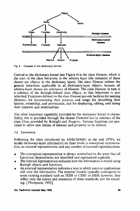
Fig. 4 Classes in the dictionary kernel
Central to the dictionary kernel (see Figure 4) is the class E lem en t, which is the root of the class hierarchy in the schema layer (the instances of these classes are objects in the dictionary layer). The class E lem en t defines the general behaviour applicable to all dictionary-layer objects, because all schema-layer classes are subclasses of E lem en t. The class E le m e n t in turn is a subclass of the Raleigh-defined class O bject, so this behaviour is also inherited. Functions defined on the class E lem en t provide facilities for naming elements, for documenting their purpose and usage, for describing their history, ownership, and provenance, and for displaying, editing, and listing their contents and relationships.
The other important capability provided by the dictionary kernel is extensibility; this is provided through the classes E lem en tC la ss (a subclass of the class C lass provided by Raleigh) and P ro p er ty . Various functions are provided to allow new classes of element and property to be defined.
7 .3 C o n v e r te r s
Following the ideas introduced by ANSI/SPARC in the mid 1970’s, we model dictionary-layer information on three levels: a conceptual representation, an internal representation, and any number of external representations: •
• The conceptual representation is always normalised in the sense that all functional dependencies are identified and represented explicitly.
• The internal representation indicates how the information is stored using Raleigh objects and functions.
• An external representation indicates a way in which users or applications will view the information. The external models typically correspond to some existing standard such as IRDS or CDIF or DDS; however, they reflect only the syntax and semantics of these standards, not the encoding. [Thompson, 1992]
ICL Technical Journal May 1992 95

Fig. 5 The Role of Converters
The role of a converter in the architecture is to translate between the conceptual representation and an external representation, in both directions. This is illustrated in Figure 5.
All three representations - the conceptual, external, and internal are encoded using the constructs of Raleigh’s functional object model. The difference between the representations is in the way the functional model is used. For example, when modelling a relational table definition, the conceptual representation includes a function on Table that yields a set of Column objects. The p ro p e r ty s y n ta x external representation (corresponding to the DDS standard) includes a function on Table that yields a character string containing the names and datatypes of the columns. The E R A external representation includes a function on Table that yields a set of Relationship objects to define the links between the Table and its columns. The g raph ica l external representation represents a relational database as an object of class DirectedGraph, whose nodes are Tables and Columns and whose arcs represent the links between them.
Because all these representations are encoded using Raleigh’s functional object model, thay are all accessible to tools using Raleigh’s OODL language.
By contrast, external encod ings conform to the detailed interface definitions of an external standard such as IRDS, CDIF, or DDS. These encodings are accessible only through the interface defined in the relevant standard; for example, a character-encoded file in the case of CDIF.
Although the number of external representations (and hence converters) is open-ended, we have identified three that will meet immediate requirements:
96 ICL Technical Journal May 1992
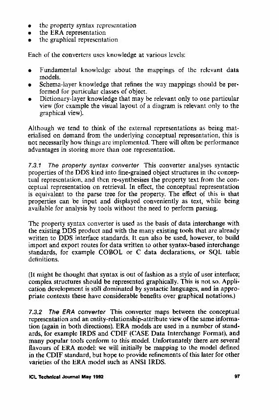
• the property syntax representation• the ERA representation• the graphical representation
Each of the converters uses knowledge at various levels:
• Fundamental knowledge about the mappings of the relevant data models.
• Schema-layer knowledge that refines the way mappings should be performed for particular classes of object.
• Dictionary-layer knowledge that may be relevant only to one particular view (for example the visual layout of a diagram is relevant only to the graphical view).
Although we tend to think of the external representations as being materialised on demand from the underlying conceptual representation, this is not necessarily how things are implemented. There will often be performance advantages in storing more than one representation.
7.3.1 T h e p r o p e r ty s y n ta x c o n v e r te r This converter analyses syntactic properties of the DDS kind into fine-grained object structures in the conceptual representation, and then re-synthesises the property text from the conceptual representation on retrieval. In effect, the conceptual representation is equivalent to the parse tree for the property. The effect of this is that properties can be input and displayed conveniently as text, while being available for analysis by tools without the need to perform parsing.
The property syntax converter is used as the basis of data interchange with the existing DDS product and with the many existing tools that are already written to DDS interface standards. It can also be used, however, to build import and export routes for data written to other syntax-based interchange standards, for example COBOL or C data declarations, or SQL table definitions.
(It might be thought that syntax is out of fashion as a style of user interface; complex structures should be represented graphically. This is not so. Application development is still dominated by syntactic languages, and in appropriate contexts these have considerable benefits over graphical notations.)
7 .3 .2 T h e E R A c o n v e r te r This converter maps between the conceptual representation and an entity-relationship-attribute view of the same information (again in both directions). ERA models are used in a number of standards, for example IRDS and CDIF (CASE Data Interchange Format), and many popular tools conform to this model. Unfortunately there are several flavours of ERA model: we will initially be mapping to the model defined in the CDIF standard, but hope to provide refinements of this later for other varieties of the ERA model such as ANSI IRDS.
ICL Technical Journal May 1992 97

The basic mappings between the functional model and ERA models are very simple: in principle, entities in the two models are equivalent; functions on entities returning a literal become attributes in the ERA model, while functions on entities returning another entity become relationships. In practice some refinements are needed depending on the capabilities of the ERA model. For example, in an ERA model where multi-valued attributes are not supported, it may be necessary to introduce an additional entity type and one-to-many relationship.
7 .3 .3 T h e g r a p h ic a l c o n v e r te r This converter maps information between the conceptual representation and the views required by the editor/browser, which supports objects such as trees, lists, and directed graphs. This converter is also capable of generating layout information, for example x , y coordinates of nodes, and routings of arcs in a network. This layout information is required by some CASE tools before data can be imported to the tool, and standards for its representation are defined in CDIF.
7 .4 D ic t io n a r y E d ito r a n d B r o w s e r
The editor/browser provides interactive capabilities to find, display, and modify dictionary information. It is generic, in the sense that it can handle any dictionary object; but being object-oriented, it is also customisable so that specialised interactions are possible based on the class of object.
The editor/browser is designed to use ICL’s KHS user interface technology. KHS provides a layer of graphical services within a standard windowing environment; this allows the Dictionary editor/browser to coexist on the desktop with tools written to the popular windowing standards. KHS has been developed by ICL from research work at the European Computer- Industry Research Centre (ECRC); it has also been used in developing the user interface for ICL products such as the Open Systems Management Centre [Small et al., 1991].
It could be argued that a dictionary system should exist in a server role only, and should not provide its own user interface; user interfaces should only be provided by the CASE tools that access the dictionary. This argument overlooks the wider role of a dictionary, which as we saw in section 1 is not merely to allow tools to share information, but to serve all the information needs of the application developer. Dictionaries originated as an aid to good system documentation, and it remains true that 80% of the work of application developers consists of maintenance rather than new development. For this work, the ability to access, analyse, and digest information about the current system design is paramount. The maintenance programmer needs full access to the information in the dictionary; design and construction tools are not enough.
98 ICL Technical Journal May 1992

The design of the Open Dictionary includes schema-layer support for a variety of common tools and target environments: for example the C and C O BO L langauages, SQL relational databases such as Ingres, and so on. However, these are architecturally nothing more than a starter set of tools to be supported. We expect a large number of additional tools to be integrated by the tools vendors themselves or by third (or fourth) parties.
The dictionary therefore needs to support a very modular schema, with individual modules being separately installable and amenable to separate upgrade. This applies both to passive schema modules (data definitions) and to active modules - those containing tools or encapsulations of tools. In a world of objects there is no architectural distinction between the two cases.
There is also a need to supply guidelines and registration services so that independently-produced schema modules can achieve consistency in matters such as naming conventions. Although it will be technically feasible for users or independent vendors to extend the schema in any way they please, we will encourage anyone doing so to join in an informal club of interested parties created to ensure an overall consistency of approach.
8 An Extended Example
In this section we take as an example a subset of the relational model. We consider how a relational database can be modelled in the open dictionary, and the way in which the various tools interact with this model. This example is used to clarify the architecture and to explain its benefits.
8 .1 T h e c o n c e p tu a l r e p r e s e n ta t io n
The conceptual representation we use is illustrated in Figure 6. The main element classes are: •
• SQLobject: this abstract class includes all objects defined in SQL, such as Tables and Indexes.
• Database: a dictionary may contain information about any number ofrelational databases.
• Table: a description of an SQL base table or view.• BaseTable: a description of an SQL base table.• View: a description of an SQL view.• Column: a description of a column of a base table or view.• DataType: a description of the pool of values from which the values in
a column are drawn.• Index: a data structure set up to speed retrieval of selection queries when
certain column values are known.
7.5 Dictionary Schema and Tools
ICL Technical Journal May 1992 99
Fig. 6 Conceptual representation of Relational Databases
We omit other concepts such as referential integrity constraints, access permissions, etc., for the sake of brevity.
Note that BaseTable and View are subclasses of Table.
There are few attributes associated with these objects, and most of them are fairly simple: we shall examine one major exception, the query-spec ifica tion that defines the derivation of a view.
The definition of SQL, taken from that in the X/Open Portability Guide, defines a q u ery-spec ifica tion as a syntactic construct:
query-specification :: =SELECT [ ALL | DISTINCT ] select-list
FROM table-reference [, table-reference ] ... t WHERE search-condition ][ GROUP BV column-name [.column-name ] ...[ HAVING search-condition ]
For example, a view might be defined as follows:
CREATE VIEW NEW.GRADUATES AS SELECT EMP.*FROM EMPLOYEE EMP WHERE EMP.DEGREE IS NOT NULL
AND EMP.JOINDATE > 1988/1/1
This is enough to illustrate that a q u ery-sp ec ifica tio n is a rather complex object.
We can model a query-sp ec ifica tio n in Raleigh as a nested list structure. For each non-terminal construct in the syntax definition we define a subclass of
100 ICL Technical Journal May 1992

the Raleigh class List; for example the top-level construct query-sp ec ifica tio n is represented by a class Q u eryS p ec ifica tio n , a subclass of L is t, containing six members, the d is tin c t indicator, the se lec t-lis t, the fro m -lis t , the w here- cond ition , the g ro u p -b y -lis t, and the having-cond ition . The view definition given above in SQL would be represented in Raleigh by the structure shown in Figure 7. (The arrows in this diagram indicate a structural decomposition; they should not be interpreted as pointers or references.)
Fig. 7 Conceptual representation of an SQL view
This nested list representation can clearly be generated by parsing the textual form of the query specification, and the textual form can be reconstructed from the nested list structure. The nested list structure, however, is more amenable to processing by software tools that wish to extract information about the query specification - for example, a tool that wants to know how many columns there are in the view, or whether the view is updatable.
Information that is likely to be commonly required, either by tools or by maintenance programmers, can be made available in the form of derived properties. For example, it is possible to define a derived property that tests whether a given SQL view is updatable. The rules for determining updat- ability of a view are defined in the SQL standard; these rules, although complex, can be translated straightforwardly into an OODL function that
ICL Technical Journal May 1992 101
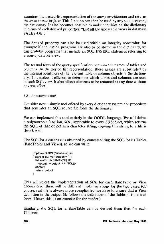
examines the nested-list representation of the q u ery-sp ec ifica tio n and returns the answer true or fa ls e . This function can then be used by any tool accessing the dictionary. It also becomes possible to make enquiries on the dictionary in terms of such derived properties: “List all the updatable views in database SALES-DB”.
The derived property can also be used within an integrity constraint; for example if application programs are also to be stored in the dictionary, we can prohibit programs that include an SQL INSERT statement referring to a non-updatable view.
The textual form of the query-specification contains the names of tables and columns. In the nested list representation, these names are substituted by the internal identifiers of the relevant table or column objects in the dictionary. This makes it efficient to determine which tables and columns are used in each SQL view. It also allows elements to be renamed at any time without adverse effect.
8.2 A n e x a m p l e to o l
Consider now a simple tool offered by every dictionary system, the procedure that generates an SQL source file from the dictionary.
We can implement this tool entirely in the OODL language. We will define a polymorphic function, S Q L , applicable to every S Q L o b je c t, which returns the SQL of that object as a character string; copying this string to a file is then trivial.
The SQL for a database is obtained by concatenating the SQL for its Tables (BaseTables and Views), so we can write:
implement SQL(Database) as { param db; var output: =
for each t in Tables(db) do output : = output ++ SQL(t)
endfor; return output
t
This will select the implementation of S Q L for each BaseTable or View encountered: there will be different implementations for the two cases. (Of course, real life is always more complicated: we have to ensure that a View definition in the output file follows the definitions of the Tables it is derived from. I leave this as an exercise for the reader.)
Similarly, the SQL for a BaseTable can be derived from that for each Column:
102 ICL Technical Journal May 1992
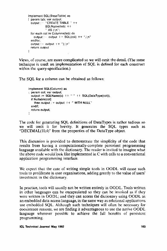
implement SQL(BaseTable) as { param tab; var output;
output := "CREATE TABLE ” ++SQLName(tab) ++" AS (\n";
for each col in Columns(tab) do output := output ++ SQL(col) ++ ",\n”
endfor;output := output ++ ");\n" return output
}
Views, of course, are more complicated so we will omit the detail. (The same technique is used: an implementation of SQL is defined for each construct within the query-specification.)
The SQL for a column can be obtained as follows:
implement SQL(Column) as { param col; var output;
output := SQLName(c) ++ “ ” ++ SQL(DataType(col)); if Nullable(col)
then output := output ++ ” WITH NULL” endif;return output;
}
The code for generating SQL definitions of DataTypes is rather tedious so we will omit it for brevity. It generates the SQL types such as “DECIMAL(10,4)” from the properties of the DataType object.
This discussion is provided to demonstrate the simplicity of the code that results from having a computationally-complete persistent programming language available with the dictionary. The reader is invited to imagine what the above code would look like implemented in C with calls to a conventional application programming interface.
We expect that the ease of writing simple tools in OODL will cause such tools to proliferate in user organisations, adding greatly to the value of users’ investment in the dictionary.
In practice, tools will usually not be written entirely in OODL. Tools written in other languages can be encapsulated so they can be invoked as if they were written in OODL; and they can access the dictionary using OODL as an embedded data access language, in the same way as relational applications use embedded SQL. Although such techniques will often be necessary for coexistence reasons, we are finding it advantageous to use the native OODL language wherever possible to achieve the full benefits of persistent programming.
ICL Technical Journal May 1992 103

Fig. 8 Conceptual representation of INGRES Databases
8 .3 A d a p t in g to o ls
Suppose that the dictionary contains the SQL model and generator described in the previous sections, and we now wish to adapt this to handle the special features of a product such as Ingres. Like any relational database, Ingres offers many extensions to standard SQL. In this section, we consider how we can re-use the standard model already defined, while specialising it for Ingres. (The approach would be similar for any other relational database.)
We define IngresDatabase, IngresTable, IngresBaseTable, IngresView, etc. as subclasses of Database, Table, BaseTable, View, respectively. Note that this leads to multiple inheritance: IngresView now inherits both from View and from IngresTable.
In addition, note that Ingres implements both Indexes and BaseTables using the same mechanisms, so many properties (such as disc location and file organisation) are applicable to both. So we introduce another abstract class IngresStoredTable, which IngresBaseTable and Ingreslndex both inherit from. The full class lattice is now as shown in Figure 8.
We can of course define additional functions on these classes to reflect the detailed options available with Ingres. For example Ingres allows a column
104 ICL Technical Journal May 1992

to be defaultable as well as nullable, so we could define a further property D efa u lta b le on IngresC olum n .
We can then adapt the SQL generator for Ingres to take note of this additional property:
implement SQL(lngresColumn) as { param col;
if Defaultable(col)then return super + + ” WITH DEFAULT” else return super
endif}
The OODL keyword super indicates a call to the unrefined implementation of the same function: in this case a call to the implementation of SQ L(C olum n). The code for generating SQL for a Table will pick up the refined code for IngresColumn and call it instead of the original code; the refined code calls the original code and if appropriate adds further detail.
This illustrates the way in the object-oriented dictionary architecture allows generic tools to be re-used and specialised to handle product variants. Note that the refinement could be carried out by a customer or third party: ICL, for example, might supply the generic tool and an Ingres variant, while a third party might customise it for a relational database product such as IBM’s DB2.
9 Summary
This paper has described some of the principal characteristics of the Open Dictionary:
• the role of the dictionary in O P E N J ra m e w o rk• the importance of extensibility and adaptability as the basis for achieving
openness, and in particular the need for the dictionary to convert information between different representations
• the reason for selecting an object-oriented approach, and the functional model in particular
The example, showing how a relational database can be modelled, illustrates the power of the approach.
Acknowledgements
INGRES is a trademark of the Ingres Product Division of ASK Incorporated.
ICL Technical Journal May 1992 105
ADDIS, T.R. and NOWELL, M.C.C. Knowledge and the Structure of Machines. In “Symbols and Neurons", IOS BV, Amsterdam, 1990.
ATKINSON, M.P. and BUNEMAN, O.P. Types and persistence in database programming languages. ACM Computing Surveys, 19(2). 1987.
BCS (British Computer Society). Report of the Data Dictionary Systems Working Party. March 1977.
BOCCA, J. MegaLog - A Platform for developing Knowledge Base Management Systems. ECRC KB Report #15. 1990.
BOURNE, T.J. The Data Dictionary System in Analysis and Design. 1CL Tech J. 1(3), pp. 292-298. Nov 1979.
BRENNER, J.B., BROWN, G.H., BRUNT, R.F., FLOWER, F.L., GALE, A.C., GLYDE, C.J., HINCKLEY, R„ HOLLINGSWORTH, D C., HUTT, A.T.F., KAY, M.H., McVITIE, D.J., PARKER, T.A., and PRATTEN, G.D. OPEN framework Technical Overview. ICL, June 1991.*
BROWN, A.P.G., COSH, H.G., and GRADWELL, D.J.L. Development Philosophy and fundamental processing concepts of the ICL Rapid Application Development System RADS. ICLTech J. 2(4), pp. 379-402. (1981). (The RADS system was subsequently marketed under the name Application Master).
BROWN, A.W. Object-Oriented Databases: Applications in Software Engineering. McGraw-Hill, 1991.
BROWN, G.H. OPENframework: Application Development Reference Architecture. ICL, Nov 1991.*
CLARKE, D., MATTHEWS, K.I. and PRATT, M. The Engineering Database. ICL Tech J., May 1992.
FISHMAN, D.H. et al. Overview of the IRIS DBMS. In Kim and Lochovsky led). Object- Oriented Concepts, Databases, and Applications. Addison-Wesley. ISBN 0-201-14410-7. (1989).
FREESTON, M. The BANG file: a new kind of grid file. Proc ACM SIGMOD Conf., San Francisco, 1987.
GALE, A.C. OPENframework: Systems Management Reference Architecture. ICL, Nov 1991*GREENWOOD, R.M., GUY, M.R. and ROBINSON, J.K., The Use of a Persistent Language
in the Implementation of a Process Support System. ICLTech. J. Vol. 8 No. I pp. 108, 1992.HOLLOWAY, S. The future of data dictionaries. Proc. BCS Data Management Specialist Croup.
Gower Press, May 1988.*HUTT, A.T.F. OPENframework: User Interface Reference Architecture. ICL, Nov 1991.*JONES, R. Repository Delay Spurs Interest in I-CASE Technology. Software Development
Monitor 3(1), Feb 1991.KAY, M.H. and R1VETT, P.J. An overview of the Raleigh object-oriented database system.
ICL Tech J. 7(4), pp. 780-798. Nov 1991.RAMFOS, A., FIDDIAN, N.J. and GRAY, W.A. A Meta-Translation System for Object-
Oriented to Relational Schema Translations. In Aspects o f Databases, Proc. 9th British National Conf. on Databases, ed. Jackson and Robinson. Butterworth-Heinemann, 1991.
SHIPMAN, D. The functional data model and the language DAPLEX. ACM TODS 6(1), pp. 140 -173. (1981).
SMALL, M., MITCALF, J.D., JOHNSTONE, J. and DOORES, J.W. OSMC: The Operations Control Manager. ICLTech J., 7(4), pp. 751-762. Nov 1991.
STONEBRAKER, M. Introduction to the Special Issue on Database Prototype Systems. IEEE Trans, on Knowledge and Data Engineering 2(1), 1990.
THOMPSON, A.K. CASE Data Integration: The Emerging International Standards. ICLTech. J. 8 (1), pp. 54, May, 1992.
*One of a series of ICL reports on OPENframework, mostly of considerable length, availableon written request from S.K. Thursfield, ICL pic, Wenlock Way, W. Gorton, Manchester M125DR, UK.
References
106 ICL Technical Journal May 1992

WARBOYS, B.C. The IPSE 2.5 project: Process Modelling as the basis for a Support Environment. Proc. 1st Int. Conf. on Software Development, Environments, and Factories, Berlin, 1989.
Standards Publications
ANSI X3.138-1988 Information Resource Dictionary System (IRDS). Oct 1988.ECMA Technical Report 149. PCTE Abstract Specification. Dec 1990.ECMA Technical Report 158. PCTE C language binding. June 1991.EIA/IS-81. CDIF - Framework for Modeling and Extensibility. July 1991.EIA/IS-82. CDIF - Transfer Format Definition. July 1991.EIA/IS-83. CDIF - Standardized CASE Interchange Meta-model. July 1991.ISO/IEC 10027:1990(E). Information Resource Dictionary System (IRDS) Framework. ISO/DIS 10728. Information Resource Dictionary System (IRDS) Services Interface.ISO/IEC N1046R. Information Resource Dictionary System (IRDS) Design Support for SQL. Object Management Group (OMG): Object Management Architecture Guide. 1991.X/OPEN. Portability Guide: Data Management. Prentice-Hall, 1988.
Biography
D r. M ic h a e l H . K a y
Michael Kay gained a Ph.D from the University of Cambridge for research into database systems in 1976. He joined ICL the following year, and has specialised in database technology ever since. He led first the development unit and then the design team for the Codasyl system IDMSX: from 1983 until 1986 he was chief designer of the document retrieval system ICLFILE. He acted as Chief Architect on the INGRES programme integrating the relational database system into ICL’s product range, and since 1989 he has been responsible for ICL’s technical strategy for data dictionary products.
He was appointed an ICL Fellow in 1989. He is a member of the team developing ICL’s OPEN\fra m e w o r k architecture, with specific responsibility for Information Management. He is also a Visiting Fellow at the Institute of Software Engineering in Belfast.
ICL Technical Journal May 1992 107
The Use of a Persistent Language in the Implementation of a Process Support
System
R. Mark Greenwood*, Michael R. Guy, D. John K. RobinsonProcess Support Centre, OPEN framework Division, ICL Kidsgrove
Abstract
T h i s p a p e r d e s c r i b e s h o w a p e r s i s t e n t l a n g u a g e , P S - a lg o l , w a s e x p l o i t e d to i m p l e m e n t a p r o c e s s s u p p o r t s y s t e m . T h e c o n c e p t s of p e r s i s t e n c e a r e e x p l a i n e d , t o g e t h e r w i th o t h e r a t t r i b u t e s o f P S - a lg o l w h i c h a d d v a l u e to it. T h e s e i n c l u d e f i r s t c l a s s p r o c e d u r e s , t h e a b i l i ty f o r a P S - a lg o l p r o g r a m to c h a n g e i ts e l f b y m e a n s of t h e c a l l a b l e c o m p i l e r , a n d t h e u n i v e r s a l p o i n t e r t y p e w h ic h p e r m i t s f l e x ib l e b in d in g .
T h e p r o c e s s s u p p o r t s y s t e m P S S s u p p o r t s t h e e n a c t m e n t o f p r o c e s s m o d e l s b y e x e c u t i n g p r o c e s s p r o g r a m s w r i t t e n in t h e l a n g u a g e PM L. T h e c e n t r a l f e a t u r e of PM L is t h e ro le . T h i s i s a n o b j e c t w h ic h c o m m u n i c a t e s w i th o t h e r r o l e s v i a i n t e r a c t i o n s , o r m e s s a g e s . T h e c e n t r a l c o m p o n e n t of P S S is a p r o c e s s c o n t r o l e n g i n e w h ic h s u p p o r t s t h e c o m p i l a t i o n a n d e x e c u t i o n of p r o g r a m s w r i t te n in PM L. R o l e s a r e p e r s i s t e n t p r o c e s s e s a n d a r e r e p r e s e n t e d a s (firs t c l a s s ) P S - a lg o l p r o c e d u r e s . I n t e r a c t i o n s a r e p e r s i s t e n t m e s s a g e s w h ic h a r e h e ld in t h e w o r k in g d a t a of a p e r s i s t e n t s c h e d u l e r .T h e PM L of a r o l e m a y b e c h a n g e d a t r u n t i m e by c o m p i l i n g n e w PM L a n d b in d in g it in to t h e s y s t e m d y n a m i c a l l y u s i n g t h e m e c h a n i s m s of P S -a lg o l .
T h e p a p e r o u t l i n e s t h e s t r u c t u r e of P S S a n d g i v e s e x a m p l e s of t h e w a y it h a s r e l i e d o n P S - a lg o l fo r i ts i m p l e m e n t a t i o n .
1 The Position of PSS
The Process Support System (PSS) [Bruynooghe et al., 1991 ] grew out of the IPSE 2.5 Project [W arboys, 1989; Snowdon, 1989]. As its name suggests, its business is the support of process; nothing about it constrains the process
•Now at the Department of Electronics and Computer Science, University of Southampton.
108 ICL Technical Journal May 1992
supported to be that of software engineering, although much of the motivation behind the system is exactly that.
ICL, in developing its flagship mainframe operating system VME, recognised in the early 1970s that a significant change in culture was necessary in the control of a large and complex software project. Completion of a project of that scale is significant enough, but is dwarfed by the problems of maintaining integrity of design and control throughout continuous evolution spanning several decades. ICL developed and used CADES (Computer Assisted Design and Evaluation System) [Pearson, 1973; Warboys, 1980] to tackle this problem. The computer assistance was a necessary component in terms of providing storage for design and code, and providing an environment for tools such as those to handle system construction and configuration management; however, the crucial aspect of the broader system vital to the longevity of the project was the procedures used to control what was allowed into the computer-based system. The process embodied in these evolving procedures was intended to ensure that checks on, for instance, the validity of the design, or the consistency of different parts of the system, had indeed been performed; the procedures were mainly paper-based, but some utilised other, smaller, databases independent of the main CADES one, and of course more tools.
Perry and Kaiser [1991] describe a model for software development environments SMP based on Structure, Mechanisms and Policies and an IFCS taxonomy, Individual, Family, City and State, which highlights the issue of scale. In terms of the Perry and Kaiser SMP model then, CADES had plenty of machine support for the Structures and the Mechanisms, but precious little for the Policies. Nevertheless, much experience was gained in handling the procedures manually, especially in dealing with the need to be able to change them while active.
It would have been over-ambitious in conceiving PSS to attempt initially to tackle an organisation as large and complex as the development of an operating system, going in effect straight for Perry and Kaiser’s City model in their IFCS taxonomy. The intermediate step necessary was to gain experience in providing and using a system which supported process, allowed the process to change, and allowed users to make use of tools not necessarily in the original scheme of things.
It is these aspects of PSS that tend most to distinguish it from other software engineering environments (this is discussed further in [Warboys, 1989]). It is also the case that most of them are built as layers on an existing database system, whereas the PSS has a computational model (the language [PML, 1990]) for the environment it provides. PS-algol on VME was simply an available engineering tool appropriate to the implementation of PSS.
Early experience with using PSS suggests that its potential usefulness is not limited merely to what is generally thought of as software engineering, but that it can be applied to many different kinds of process. We have no reason
ICL Technical Journal May 1992 109
to suppose that our architecture is deficient in any way that would prevent it from being used for a large and complex process, although there are issues of scale and performance that will have to be tackled.
2 Persistence and PS-algol
The IPSE 2.5 Project decided to implement the PSS in the persistent programming language PS-algol [Atkinson et al., 1983]. Although the choice of language was the result of debate we will not pretend that all the advantages of it were recognized in advance. We will instead give a brief description of the more important language features relevant to PSS and in later sections show how these features were exploited.
Persistence itself is a new technology for easing the task of writing programs. Persistent languages work on the principle that data and code last as long as they are reachable. One extreme way of viewing it is that all data and code created by a program lasts for ever, but for the sake of efficiency language systems have garbage collectors which discard data which is no longer accessible. From this simple definition many advantages can be gained, and some of these will be explained in the subsection on PS-algol. First we give a description of a persistent store which is required to support a persistent language.
2.1 The Persistent Store
Persistent store can be viewed as the next logical step after virtual store [Guy, 1987], The introduction of virtual store enabled a programmer to concentrate on the task of programming without having to be too aware of the size of the program. Before the advent of virtual store a large program had to be divided into overlays which were brought in from disc when required. If the overlay structure was wrong either the program did not run or it ran very slowly. Virtual store introduced what is termed a one-level store.
It was, however, still necessary for the programmer to be aware whether the data accessed by a program was held within the program’s work space or in a file or database residing outside the program. Accessing and updating the content of a file meant explicit code to transfer a copy of the data in the file into the program, update its contents, and copy it back. Persistent store avoids the need for this. Data held permanently on disc is accessed and updated with the same ease as data held in main memory.
To achieve this certain extensions are needed to the virtual store model.
The first extension allows data to be written back to permanent memory under the control of the program. With virtual store, pages are written to secondary store on disc when the virtual store manager needs the space in main store. This results in a disc copy which is usually both inconsistent
110 ICL Technical Journal May 1992

with itself and incomplete; this does not matter in the virtual store scenario, because the role of secondary storage is simply to provide the transient support of main store. With persistent store, although data and code are fetched when needed, they are written back in a controlled manner to ensure the consistency of the store’s contents. There are several ways that this can be done. One is to have an explicit com m it command in the language; this can be called, for example, just before the program completes. Another is to encapsulate an operation in the program within a transaction. Yet another is to hide the need for commitment from the programmer altogether. In this case it may be necessary for the data being written back to permanent store to include the state of the program being executed. The first two mechanisms are provided by PS-algol. The third mechanism is the one that comes with PML, the language which the PSS implements.
The next extension treats the disc as an object store for variable-length objects, rather than a page store containing fixed-length pages. An object will relate to some language feature, for example a record, a code body, a string, or the stack frame (or local name space) of a procedure. A persistent store will contain a large number of such objects. References are no longer implemented by virtual addresses, which can be fabricated in a program, but by explicit inter-object pointers. Provided the language for programming the store implements references only in terms of these pointers, this enables the store to perform garbage collection and at the same time maintain the referential integrity which is central to persistence.
The last extension allows concurrent programs to interact when executing in the same persistent store; it adds a mechanism for controlling the way they do it. One approach is to give them access to the same space and ask them to control their interaction via semaphores. Another approach, which we have adopted, is implicitly to lock any object which is fetched into the work space of a program and to unlock it at the end of the transaction in which it was fetched. Before unlocking objects the transaction will selectively commit all the changes made within that transaction. Thus a consistent set of data is available to another program.
PML is a persistent language, as will be explained later. So is PS-algol, the language chosen for the implementation of PML. Raleigh [Kay and Rivett, 1991] is implemented in MegaLog, the persistent Prolog from the ECRCf [Bocca, 1991], PS-algol and MegaLog form an interesting comparison. One of the benefits of persistence as applied to a procedural language, such as one of the algol family, is that objects which encapsulate data inside them and which are accessed by procedural interfaces can be stored permanently without having to perform any transformation on them. This sort of benefit is already in Prolog. However, with traditional Prologs the whole ‘database’ has to be read into working store in one go and updated in its entirety.
fECRC is the European Computer Research Centre in Munich.
ICL Technical Journal May 1992 111
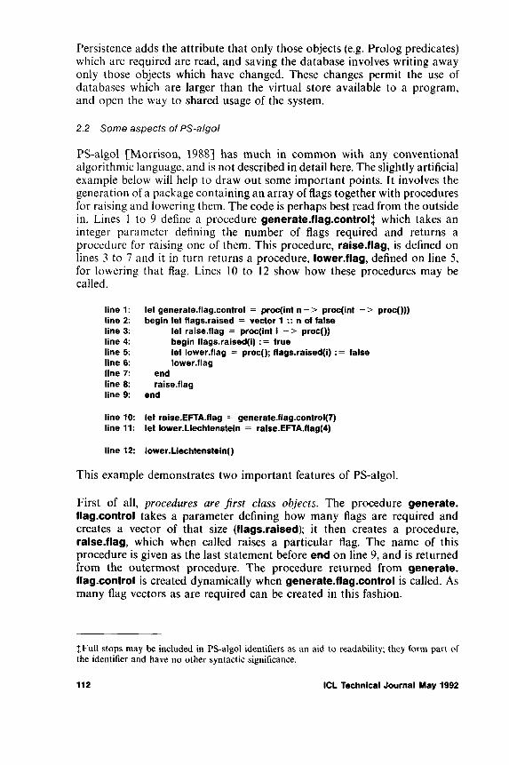
Persistence adds the attribute that only those objects (e.g. Prolog predicates) which are required are read, and saving the database involves writing away only those objects which have changed. These changes permit the use of databases which are larger than the virtual store available to a program, and open the way to shared usage of the system.
2.2 S o m e a s p e c ts o f P S - a lg o l
PS-algol [Morrison, 1988] has much in common with any conventional algorithmic language, and is not described in detail here. The slightly artificial example below will help to draw out some important points. It involves the generation of a package containing an array of flags together with procedures for raising and lowering them. The code is perhaps best read from the outside in. Lines 1 to 9 define a procedure generate.flag.control| which takes an integer parameter defining the number of flags required and returns a procedure for raising one of them. This procedure, raise.flag, is defined on lines 3 to 7 and it in turn returns a procedure, lower.flag, defined on line 5, for lowering that flag. Lines 10 to 12 show how these procedures may be called.
line 1: let generate.flag.control = proc(int n - > proc(int - > proc()))line 2: begin let flags.raised = vector 1 :: n of falseline 3: let raise.flag = proc(int I - > proc())line 4: begin flags.raised(i) : = trueline 5: let lower.flag = proc(); flags.raised(i) : = falseline 6: lower.flagline 7: endline 8: raise.flagline 9: end
line 10: let raise.EFTA.flag = generate.flag.control(7) line 11: let lower.Liechtenstein = raise.EFTA.flag(4)
line 12: lower.Liechtenstein()
This example demonstrates two important features of PS-algol.
First of all, procedures are f i r s t c lass ob jects. The procedure generate, flag.control takes a parameter defining how many flags are required and creates a vector of that size (flags.raised); it then creates a procedure, raise.flag, which when called raises a particular flag. The name of this procedure is given as the last statement before end on line 9, and is returned from the outermost procedure. The procedure returned from generate, flag.control is created dynamically when generate.flag.control is called. As many flag vectors as are required can be created in this fashion.
{Full stops may be included in PS-algol identifiers as an aid to readability; they form part of the identifier and have no other syntactic significance.
112 ICL Technical Journal May 1992
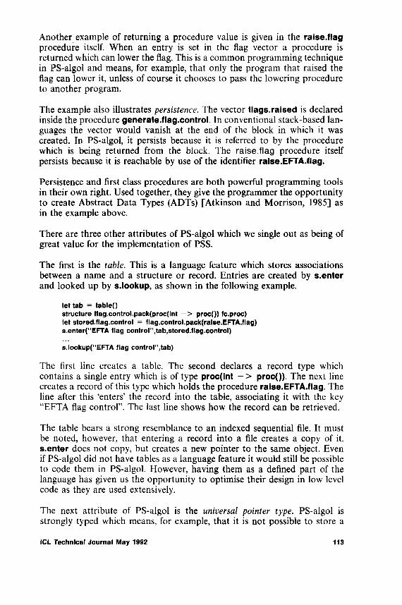
Another example of returning a procedure value is given in the raise.flag procedure itself. When an entry is set in the flag vector a procedure is returned which can lower the flag. This is a common programming technique in PS-algol and means, for example, that only the program that raised the flag can lower it, unless of course it chooses to pass the lowering procedure to another program.
The example also illustrates persistence . The vector flags.raised is declared inside the procedure generate.flag.control. In conventional stack-based languages the vector would vanish at the end of the block in which it was created. In PS-algol, it persists because it is referred to by the procedure which is being returned from the block. The r a i s e . f l a g procedure itself persists because it is reachable by use of the identifier raise.EFTA.flag.
Persistence and first class procedures are both powerful programming tools in their own right. Used together, they give the programmer the opportunity to create Abstract Data Types (ADTs) [Atkinson and Morrison, 1985] as in the example above.
There are three other attributes of PS-algol which we single out as being of great value for the implementation of PSS.
The first is the table . This is a language feature which stores associations between a name and a structure or record. Entries are created by s.enter and looked up by s.lookup, as shown in the following example.
let tab = tablet)structure flag.control.pack(proc(int - > proc()) fc.proc) let stored.flag.control = flag.control.pack(ralse.EFTA.flag) s.enter(“EFTA flag control”,tab,stored.flag.control)
s.lookupf'EFTA flag control”,tab)
The first line creates a table. The second declares a record type which contains a single entry which is of type proc(int - > proc()). The next line creates a record of this type which holds the procedure raise.EFTA.flag. The line after this ‘enters’ the record into the table, associating it with the key “EFTA flag control”. The last line shows how the record can be retrieved.
The table bears a strong resemblance to an indexed sequential file. It must be noted, however, that entering a record into a file creates a copy of it. s.enter does not copy, but creates a new pointer to the same object. Even if PS-algol did not have tables as a language feature it would still be possible to code them in PS-algol. However, having them as a defined part of the language has given us the opportunity to optimise their design in low level code as they are used extensively.
The next attribute of PS-algol is the un iversa l p o in te r type. PS-algol is strongly typed which means, for example, that it is not possible to store a
ICL Technical Journal May 1992 113

string in an integer. This enables the compiler to make more effective checks on the correctness of a program. However, in a persistent system some procedures will be written after the data on which they operate, and some data will be created after the procedures to which they are submitted. The universal pointer type means that a variable of type pntr may point at a PS- algol structure of any type. The type check on the structure is made when the structure is accessed rather than at compilation time. In particular, a table contains entries of type pntr, which permits anything to be stored in a table by wrapping it up in a PS-algol structure.
The last attribute is the callab le com piler. It is possible for a program to modify itself by compiling some PS-algol source embedded in a string into a procedure which may then be called in addition to or alternatively to its existing procedures.
3 Process Support System Overview
The Process Support System (PSS) supports the enactment of process models by executing programs written in the process modelling language PML. A process model is a set of roles each of which encapsulates its local data and represents an independent thread of execution. Roles can communicate with one another through interactions which are uni-directional, asynchronous, buffered channels.
The PSS system is composed of three architectural elements: the Process Control Engine (PCE), the UI servers and the tool servers (Figure 1). An instance of the UI server is run on each user’s workstation. The act of logging in connects the server to the PCE. A high-level protocol is used to communicate the contents of the display to the workstation and the user’s actions back to the PCE. A similar login procedure is performed by the tool server.
The basic scenario is that a PSS service will be started, either automatically or by an operator, and the process will re-start executing. The users and tools can log in and out of the PSS and participate in the process. Users and tools can be considered as processors, just like the machine executing the PCE, which execute their part of the process. The system is dynamically evolving with new roles, interactions, users and tools becoming involved in, or dropping out of, the process.
A user logging in to the central PCE will be connected to a user agent representing his or her view of the executing process. There is a many-to- one mapping between roles and users and correspondingly the user’s view is structured into a role agenda, with one entry per role, and an action agenda for each role.
Roles are persistent processes. Their persistence is orthogonal both to the login and logout of users and to the stopping and re-starting of the PCE
114 ICL Technical Journal May 1992
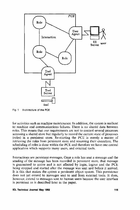
Fig. 1 A rch itectu re of th e PCE
for activities such as machine maintenance. In addition, the system is resilient to machine and communications failures. There is no shared data between roles. This means that our requirements are not to control several processes accessing a shared store but regularly to record the current state of processes (roles) in a persistent store. Re-starting the PCE is merely a matter of retrieving the roles from persistent store and resuming their execution. The scheduling of roles is done within the PCE and therefore we have one central application which supports many users, and external tools.
Interactions are persistent messages. Once a role has sent a message and the sending of the message has been recorded in persistent store, that message is guaranteed to arrive and is not affected by login, logout and the PCE being stopped and started after the message was sent and before it arrived. It is this that makes the system a persistent object system. This persistence does not yet extend to messages sent to and from external tools. It does, however, extend to messages sent to human users because the user interface is persistent as is described later in the paper.
ICL Technical Journal May 1992 115

So, what is it about PSS that made the implementation of it in PS-algol on VME the “right” thing to do? Many factors contributed; some are listed below.
First, in general, there is the important benefit that it is simpler, quicker and less error-prone to use a truly persistent language that treats persistence as an orthogonal property of data. Strictly, the “persistence” of an object is the length of time for which it exists, irrespective of how it is stored; however, the term tends to be used in particular to refer to objects which reach nonvolatile memory - the Persistent Store. (It is only then that they can be regarded as participating in an atomic transaction, and be available for sharing between concurrently executing programs.) The point about a language treating persistence as an orthogonal property of data is that it unburdens the programmer from the traditional situation of having to deal with mappings of his data which differ according to how long the data objects are going to exist.
But to be more specific, “Process” is about people (or tools) interacting with each other, performing tasks. Each person may play many roles - often intermittently. Resumption of the last state of play in a particular role is the very essence of the nature of process execution. The state may have changed in the meanwhile only as a result of the passage of relevant time, or by the interactions of others in their roles. The machine supporting the system may have suffered a power cut, or communication failure, but on the restoration of service, the roles must be unaffected. With persistence, this comes free.
Although one can argue that code is only a type of data, traditional databases tend not to cater for the storage of code. But the procedures which comprise the process are themselves liable, indeed likely, to change, and it is helpful if they and the data they operate on are subject to the same controls and support. An argument against allowing code and data to coexist has been that segregation was necessary for the integrity of the system - “don’t overwrite bits of code, and don’t try to execute data”. With PS-algol’s strong typing, extending to run-time type checking, there is no longer any reason to abandon the benefits of keeping them together.
The other aspect of change, vital as far as process is concerned, is that it must be possible for the process to evolve while live. Incorporation of new or modified code into the running system is necessary, and greatly assisted by PS-algol’s treatment of code as a first-class object, by its provision of a callable compiler as a standard function, and by the flexibility of binding allowed by PS-algol’s universal polymorphic pointers. A further aid to binding lies in the provision of tables, each entry representing a binding between a name and a data object.
4 PS-algol for PSS
116 ICL Technical Journal May 1992

To summarise, features of PS-algol of particular relevance and importance to the PSS implementors were:
• first-class procedures• orthogonal persistence• callable compiler• strong typing• universal pointer type• tables
5 Process Control Engine Im plem entation
The Process Control Engine (PCE) provides a single environment for the development and execution of PML. A new PCE contains a single base role with a single action. This action provides the capability of accepting PML, compiling it and merging it into the functionality of the base role. The PCE is written in PS-algol, that is both the scheduler which calls the compiled PML and also the support routines which are called by the compiled PML. The PML compiler generates PS-algol which is then compiled by the PS-algol compiler.
We shall not discuss PML in detail. The following section gives an example which illustrates several aspects of the system and provides a focus for the following description of how PS-algol is exploited.
5.1 PML Introduction
PML is the language developed and exploited by the IPSE 2.5 Project to write executable process models. It has been influenced by the requirements modelling language RML [Ould, 1988] and early prototype implementations were Smalltalk-based. PML is a class-based language with single inheritance. The class hierarchy supports three kinds of classes: entities, actions and roles. Entity class definitions create record types. Action class definitions introduce procedures, and role class definitions are schemas for subsequent creation of independently executing roles. In addition, interactions support inter-role communications.
In PML, compilation means change; the introduction of new PML into the system is always done as a dynamic change to a currently executing role instance. Because of the potential longevity of roles their dynamic evolution is vital. This is provided by a predefined action BehaveAs which takes a string of PML source text and a role to be changed. The PML text is compiled into a set of changes which are applied to the role.
When a system is started there is one initial role, assigned to the user root, which allows the user to supply PML text to be applied to it (Figure 2). This text can change the role allowing it to start further roles. In turn these roles
ICL Technical Journal May 1992 117

Fig. 2 Initial Role
may have the ability to change themselves, or to be changed by roles which have a reference to them. Figure 3 gives an example piece of PML text.
The PML text in Figure 3 has three sections: the definition of a role class ChangeableRole, the definition of an entity class RolePack and modifications to the role instance. All classes are seen as being composed of named components which can be replaced in a subclass definition. The use of guard expressions, when, provides a way of separating executable components. Compiling this PML into the role will extend the role’s environment with the classes ChangeableRole and RolePack, add three new resources to the role’s local data and two new actions to its behaviour. If present, existing resources and actions will be overwritten. The execution of a role’s actions is controlled by triggers; for user actions, which include Modify, View- Resource and QueryString, the guard expression is augmented by a test that the user has selected the action from the action agenda. The effect of compiling this text is that the role to which it was applied will now offer its user (Figure 4) the chance to name and start a role of class ChangeableRole and store a record of this in its myroles resource. When a role of class Changeable Role is started it will allow the user to supply some text which it will compile as a change to itself. If there are errors in the PML text then the error message will be displayed and no change will be applied to the role.
This example illustrates several key requirements on the PCE:
• creating a new thread of execution - StartRole• intra-role scheduling through trigger evaluation• communication with the user through predefined actions• creation of a new record structure NewEntity• compilation of PML source text
118 ICL Technical Journal May 1992

classesChangeableRole isa Role with resources
■odification : String { ’\n’> errors: String warnings: String
actionsmodify: { NodifyC agendaLabel = ’Modify this role’,
label = ’Type in modification to this role ’, object = modification);
BehaveAs( rolelnst = role,modification = modification,compilationErrors = errors, earnings = earnings) >
when trueshoeErrors: { VieeResource( agendaLabel = 'View compilation errors’,
object = errors,label = 'Error messages from PML Compiler’);
Assignt to = errors ) > ehen nonnil errors
endeith < end definition of ChangeableRoleRolePack isa Entity eithassocs
therole : ChangeableRole parts
raame : Stringendeith ! end definition of RolePack
resources ! start of modification to role instance name : String { ’Role 1 ’ > myroles : collof RolePack { > neerp : RolePack
actionsstartr : { QueryStringC agendaLabel = ’start role ?’,
icon = ’UserAction’, question = ’Role name?’, answer = name ) ;
HewEntityC class = RolePack, object = neerp, rname = name ) ;
StartRole( rolelnst = neerp.therole, agendaLabel = name ) }
ehen trueaddr : { AddToCollection( item = neerp, collection = myroles );
Assign( to = neerp ) > ehen nonnil neerp
! end modification to role instance
Fig. 3 PML E xam ple
Other facilities not illustrated include: •
• giving and receiving data through interactions• communication with external tools through predefined actions• creating a procedure template through defining an action class• exploitation of class-based sub-typing
ICL Technical Journal May 1992 1ig

Fig. 4 Initial Role after compiling Example
5 .2 S c h e d u l i n g R o l e s
The top level of the PCE is a lightweight scheduler which is responsible for timeslicing the processor between roles. It also handles incoming messages and performs regular checkpoints. It is implemented as an abstract data type with the following interfaces:
Start - proc( proc() read.event; proc() wait, event)Stop - proc()Schedule - proc( proc() process; bool front - > proc())
The Start interface is called when the PCE restarts; its parameters are used for handling incoming messages. The scheduler maintains a round-robin queue of ready roles, with each entry in the queue containing a procedure which is the continuation of the role’s execution. The scheduler calls the first procedure and, when it returns, moves to the next procedure and calls it. The procedures are designed to be altruistic so that no role hogs the processor. All the entries in the scheduler queue correspond to roles which have work to do. The Schedule interface is used to add a role to the ready queue; it returns a procedure to remove it from the queue. This is used when a role must wait for data, from its user or from an interaction. The boolean variable front determines whether the role is placed at the front of the scheduler queue and permits a limited amount of priority scheduling. It is used to give priority to roles processing messages coming directly from the user interface.
The system’s resilience to failure comes from the scheduler’s regular calling of PS-algol’s commit standard function which ensures that the current system state is recorded on stable store (usually disc). A commit is performed whenever the ready queue is empty or when a message has been received from the user interface.
120 ICL Technical Journal May 1992
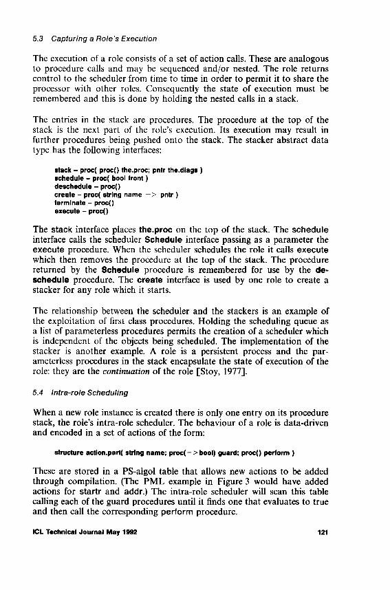
5.3 Capturing a Role’s Execution
The execution of a role consists of a set of action calls. These are analogous to procedure calls and may be sequenced and/or nested. The role returns control to the scheduler from time to time in order to permit it to share the processor with other roles. Consequently the state of execution must be remembered and this is done by holding the nested calls in a stack.
The entries in the stack are procedures. The procedure at the top of the stack is the next part of the role’s execution. Its execution may result in further procedures being pushed onto the stack. The stacker abstract data type has the following interfaces:
stack - proc( proc() the.proc; pntr the.diags )schedule - proc( bool front)deschedule - proc()create - proc( string name - > pntr )terminate - proc()execute - proc()
The stack interface places the.proc on the top of the stack. The schedule interface calls the scheduler Schedule interface passing as a parameter the execute procedure. When the scheduler schedules the role it calls execute which then removes the procedure at the top of the stack. The procedure returned by the Schedule procedure is remembered for use by the deschedule procedure. The create interface is used by one role to create a stacker for any role which it starts.
The relationship between the scheduler and the stackers is an example of the exploitation of first class procedures. Holding the scheduling queue as a list of parameterless procedures permits the creation of a scheduler which is independent of the objects being scheduled. The implementation of the stacker is another example. A role is a persistent process and the parameterless procedures in the stack encapsulate the state of execution of the role: they are the co n tin u a tio n of the role [Stoy, 1977],
5.4 Intra-role Scheduling
When a new role instance is created there is only one entry on its procedure stack, the role’s intra-role scheduler. The behaviour of a role is data-driven and encoded in a set of actions of the form:
structure action.part( string name; proc( - > bool) guard; proc() perform )
These are stored in a PS-algol table that allows new actions to be added through compilation. (The PML example in Figure 3 would have added actions for startr and addr.) The intra-role scheduler will scan this table calling each of the guard procedures until it finds one that evaluates to true and then call the corresponding perform procedure.
ICL Technical Journal May 1992 121

The p e r f o r m procedure consists of a sequence of action calls. When it calls a user-defined action it places a parameterless procedure on the stack which represents the continuation of itself. This is an important use of first class procedures.
The use of tables provides the flexibility for dynamic change since individual entries in the table can be overwritten, and new entries added.
5 .5 Communication with the User
The intra-role scheduling outlined above is complicated by the requirements of user actions and taking data from interactions. A user action is executed if its guard is true and the user has selected the action from the action agenda. The following sequence illustrates how the PCE handles user input.
1. The intra-role scheduler builds an offer of those user actions whose guards are true, sends this to the user agent along with a reply procedure and then deschedules the role.
2. The user agent sends the commands to the user interface server to update the role’s action agenda with the offered actions (Figure 4).
3. The user selects one of the actions by double-clicking.4. The user agent receives this information and calls the reply procedure
which schedules the role.5. The intra-role scheduler identifies that there is a chosen user action and
selects it. One of the user agent’s support procedures will be called passing a reply procedure. Once again the role is descheduled.
6. The user agent sends the commands to the user server which will create a new window on the user’s screen (Figure 5).
7. The user enters some data, for example the role name, and confirms completion.
8. The user agent receives this data and calls the reply procedure which schedules the role.
The user agent maintains a record of the current windows which are on a user’s screen. As the user agent is in the persistent store this automatically provides a persistent user image. When a user next logs onto the system the display will contain the same windows as when he, or she, logged out unless subsequent execution of the process program has caused changes to the user’s view. This is most graphically illustrated when a user logs in at one terminal when currently already logged in at another; the windows are transferred from one terminal to another.
One of the most convincing examples of the benefits of persistence is the ease with which a persistent user image can be maintained.
122 ICL Technical Journal May 1992

Fig. 5 Naming a New role
5.6 Entity Creation
In PML it is possible to create a subclass of an entity class by adding extra named fields to it. An instance of such an entity may be used wherever an instance of its parent class may be used. This feature is known as subtyping. Unfortunately PS-algol does not support subtyping; a PS-algol structure, which corresponds to a record, must have precisely the correct format when it is used. We overcome this by storing the fields of an entity in a PS-algol table, in which the names of the fields of the entity are the keys.
Although the entries in the tables are all structures they can all be referred to by a variable of type pntr, the universal pointer type. The table itself is of type pntr. The use of tables to represent all entity types does not allow the language’s type system to be broken since the type checker ensures that only valid operations are attempted or a run-time type error is given. Entity creation is therefore creating a PS-algol table and entering the initialisation values. If no initial value is supplied in the class definition, as for rname in Figure 3, then the initial value is ‘nil’. This is a valid value for all PML types: it can be tested with the functions isnil and nonnil; any other operator causes a run-time error.
5.7 Role Creation
Creating a new thread of execution is achieved by generating a structure which represents the new role instance. The following steps are taken on creating a new role instance:
1. generate a new role instance structure
ICL Technical Journal May 1992 123

2. generate a stacker for the new role and assign it to the field in the instance structure
3. introduce the role to its user agent4. stack the intra-role scheduler5. schedule the role.
The view on the screen after creating the new role is shown in Figure 6.
Fig. 6 S ystem with new ly c re a te d C h an g eab leR o le
5.8 Compilation and Change
A PSS system is modified by compiling PML text and binding it into the running system. PML text is first compiled into PS-algol; this in turn is compiled into a PS-algol procedure, which may then be called in the normal way. The binding is achieved by storing the procedure value for later use by updating a PS-algol table. This technique draws on that of the PS-algol object store browser [Dearie and Brown, 1988].
The unit of PML compilation is a string of PML text. This will contain a number of class definitions followed, optionally, by changes to the role
124 ICL Technical Journal May 1992

instance structure. Either the compilation will be successful, changing the role instance, or the compilation will fail, returning errors. During the compilation process this text is divided into segments with each segment being either a class definition or the modification to the role instance. A class definition is compiled into a generator procedure which is stored in the role’s classes table. The role instance modification is compiled into a procedure which is immediately applied to the role instance. This procedure may add values to the data and actions tables. For each segment of compilation the PML is translated into PS-algol which is then compiled using PS-algol’s callable compiler.
It must be remembered that all compilation changes the environment in which it takes place. This means that compilation is performed in the context of the role’s current type environment. Successful compilation will involve updating this environment as well as the generation of procedures mentioned above. As a result each role has its own independent type environment. Subsequent compilations may lead to divergence between the types in the starting and started roles. One result of this is that run-time type checking may be needed for exchanging data between roles. The PS-algol source for our ChangeableRole is outlined in Figure 7. The line “ let instance = ...” shows how the inheritance hierarchy is exploited. Each generator looks up the generator of its superclass and calls it, eventually one of the predefined classes Role, Action or Entity is reached, the appropriate instance structure is created and this is then modified by each of the generators. The code following this line is thus the modifications which ChangeableRole makes to its superclass. For each element in the role’s r e s o u r c e s section there is a statement to enter the element in the role’s data table. For each action the behaviour of the action is translated into a procedure, for example m o d i f y .e x , and the expression following w h e n into a procedure returning a boolean value. These t w o procedures are placed in an a c t i o n . p a r t structure which is added to the actions table. The addition of entries to tables provides the required dynamic evolution since previous entries will be overwritten. In addition the procedures in the actions table always perform a lookup on the data table to obtain any value. This provides a method of obtaining the correct entry even when further change to the role changes data table entries.
The PML compiler is built using the compiler componentry method described in [Dearie, 1988], Each of the major components, including the code generator, lexical analyser and type checker, is a generator procedure which returns a structure containing a set of interface procedures which is passed as a parameter to other components as required. This method has no problem coping with the fact that the type checker needs to be passed the role’s type environment as a parameter. In addition, separate roles performing BehaveAs will generate new instances of the compiler with common code but separate data spaces which allow us to interleave their processing at the compilation segment level.
ICL Technical Journal May 1992 125

proc( pntr classes -> pntr ) begin
let instance = s.lookup( "Role", classes )( Role.gen )( classes ) let data = instance( data )! ... other declarations of local names used in this procedure s.enter( "modification", data, Datalnst( ... ) )! ... addition of other local data let modify.ex = proc() ; begin ... end let modify.guard = proc( -> bool ) ; begin ... end s.enter( "modify", actions,
action.part( "modify", modify.guard, modify.ex ) )! ... addition of other actions instance
endFig. 7 Exam ple PS-algol for PML
5.9 Interactions
Interactions are uni-directional message channels. They have two ends: a GivePort and a TakePort. Creating an interaction involves calling a generator procedure which returns a structure containing two interfaces.
structure GlveToken( proc( pntr ) Give.Data ;proc( - > bool) Data.present.g )
structure TakeToken( proc( - > pntr ) Take.data ;proc( - > bool) Data.present.t; proc( proc() - > proc()) Wait.for.data )
A GiveToken corresponds to a PML GivePort and a TakeToken to a TakePort. The current implementation is one-to-one communication with one role having the GivePort and one role the TakePort; a many-to-one extension is under development. It is important to note that interactions are persistent; the data which is queued in an interaction between roles is not lost when the system is shut down. The Wait.for.data interface provides a further example of the use of a call back mechanism. The role which calls this interface deposits a procedure which will be called when data arrives and the result of this call is a procedure which it can use to remove this call back. Interactions are polymorphic and give an example of how we exploit PS-algol’s pntr type. As all PML data is represented as structures the implementation of interactions will cope with all PML entities including the predefined integers, reals, strings and booleans, as well as references to role instances and GivePorts and TakePorts themselves. The ability of interactions to be passed as data down other interactions means that the interrole communication can dynamically evolve under the control of the process program.
126 ICL Technical Journal May 1992

6 T im e and Scale
The first process support system to use PS-algol was the IPSE 2.5 baseline 4 release 1 system. Design began around May 1989 and this version was completed in September. Since then there has been ongoing development work with the seventh version of the system currently in development. The applications performance has been improved both through implementation improvements and through developments of the underlying object store on VME, which is described in [Guy and Robinson]. There is currently a major revision of the PML language and the system’s handling of external tools taking account of existing experiences with using the system. A pilot application has already received live usage in ICL’s Customer Service organisation.
The PSS system may be considered either large or small depending on the background of the observer. The PCE part itself comprises approximately 32 000 lines of PS-algol.
The Customer Service pilot application utilises:
• 30 Megabyte persistent store, containing about• 600000 objects, of which• 16000 are procedure bodies, and which runs for• 10 to 12 hours per day, 5 days per week.
PCE implementations exist for SUN3, SUN4 and ICL Series 39 machines. UI servers have been written for NeWS, and X Windows§ running on SUN workstations and Microsoft Windows running on PCs. Tool servers exist for SUN3, SUN4, PC and Series 39 environments.
7 Conclusions
The PS-algol callable compiler, table structures and universal pointer type are all features which have been exploited in implementing the Process Control Engine. However, the most powerful feature in terms of system development is the first class procedure: the ability for procedures to be passed as parameters, returned as results and stored in structures. The benefits of persistence, like those of a good butler, are greater for the fact that they are not immediately apparent. The implementation of roles employed the full modelling power of the language without any need to consider how long the data would exist for.
The most important facts about the PSS system are that it does work and it is used. There is no doubt in the minds of the PCE developers that the persistent language PS-algol has proved its efficacy in producing an execu-
§ X Window System is a trademark of Massachusetts Institute of Technology.
ICL Technical Journal May 1992 127

tion system for PML. It is the opinion of the developers that using a language with orthogonal persistence has been crucial both for the modelling power it provides and for the resulting programmer productivity. The system is key to our ongoing work: gaining “real” experience with a process support system, and understanding the needs of long-lived persistent applications of a reasonable size.
8 Acknowledgem ents
The VME-based version of PS-algol evolved significantly during the PISA Project. Both PISA and IPSE 2.5 were funded by Alvey, and thanks are due to all those involved in these projects.
We should like to thank those who had the foresight to choose PS-algol for the implementation of PSS. The design of PSS was led by Bob Bruynooghe, together with Jeff Parker and Alan Dearie.
References
ATKINSON, M.P., BAILEY, P.J., CHISHOLM, K.J., COCKSHOTT, W.P. and MORRISON, R. An Approach to Persistent Programming. The Computer Journal, 1983,26 (4), pp. 360-365.
ATKINSON, M.P. and MORRISON, R. Procedures as persistent data objects. ACM TOPLAS,7(4), 1985.
BOCCA, J.B. MegaLog - A Platform for developing Knowledge Base Management Systems.International Symposium on Database Systems for Advanced Applications, Tokyo, April 1991.
BRUYNOOGHE, R.F., PARKER, J.M. and ROWLES, J.S. PSS: A System for Process Enactment. Presented to 1st International Conference on Software Process, Los Angeles. 21-22 October 1991.
DEARLE, A. On the Construction of Persistent Programming Environments. Universities of Glasgow and St Andrews Persistent Programming Research Report 65, June 1988.
DEARLE, A. and BROWN, A.L. Safe Browsing in a Strongly Typed Persistent Environment. The Computer Journal 31(6): 540-544, 1988.
GUY, M.R. Persistent Store - Successor to Virtual Store. In: Persistent Object Systems: their design, implementation and use (Proceedings of the Appin workshop, August 1987). Eds. Atkinson, M.P., Buneman, O.P. and Morrison, R. Universities o f Glasgow and St Andrews Persistent Programming Research Report 44, August 1987.
GUY, M.R. and ROBINSON, D.J.K. The Implementation of a Persistent Store for PS-algol. In preparation.
KAY, M.H. and RIVETT, P.J. An Overview of the Raleigh Object-Oriented Database System. ICLTech. J, November 1991.
MORRISON, R. PS-algol Reference Manual. Fourth Edition. Universities of Glasgow and St Andrews Persistent Programming Research Report 12, February 1988.
OULD, M.A. and ROBERTS, C. Defining formal modes of the software development process.In Software Engineering Environments. Ed. Brereton, P. Ellis Horwood, Chichester, UK 1988.
PEARSON, D. CADES. Computer Weekly, July 26th, August 2nd, August 9th 1973.PERRY, D.E. and KAISER, G.E. Models of Software Development Environments. IEEE
Transactions on Software Engineering, 7(3): 283-295, March 1991 7.PML Reference Manual. IPSE 2.5 Project Document STL/608/00070, December 1990. SNOWDON, R.A. An Introduction to the IPSE 2.5 Project. ICLTech. J., 6(3): 467-478, 1989. STOY, J.E. Denotational Semantics. MIT Press, 1977.WARBOYS, B.C. VME/B a model for the realisation of a total system concept. ICL Tech. J.,
1980.
128 ICL Technical Journal May 1992

WARBOYS, B.C. The IPSE 2.5 Project: A Process Model Based Architecture. In: Software Engineering Environments: research and practice. Ed. Bennett, K.H., Ellis Horwood, Chichester, UK 1989.
Biography
R .M . Greenwood
Mark Greenwood spent several of his formative years at the University of St Andrews where he gained a BSc in Computer Science in 1985 coincidentally work was in progress there at the same time on PS-Algol. His career has progressed in a southerly direction starting with 18 months as an operating system support programmer for Burroughs in Cumbernauld. In 1987 he moved to Newcastle-under-Lyme and STC Technology Limited where he worked on a variety of software engineering projects within ICL/STC including the implementation of the PSS system. He is now reachable at the University of Southampton where he has just started a PhD in process modelling supervised by Professor Peter Henderson.
Dr. Michael R. Guy
After graduating from Oxford University in 1962 with a Mathematics degree, Michael Guy started his career in computing in LEO Computers Limited, working on the operating system for LEO III. Dissatisfaction with the lack of a theoretical foundation for his work led him to study for a PhD at the University of Newcastle upon Tyne. After three and a half years in the Systems Development Department of Wiggins Teape Ltd he rejoined what had become ICL in 1971. The next 15 years were spent in the team developing VME, gaining experience in various roles including designer, project manager and design strategist, and working on various topics including record management, integrity and recovery for both batch and TP modes of working, CAFS, the performance aspects of virtual store and the concepts of integrated and distributed recovery. After that he transferred to STC Technology Ltd where he worked on the Alvey Project entitled Persistent Information Space Architecture in which he contributed through the design and implementation of a stable store for the VME implementation of PS-algol, and by extending the PS-algol language to include transactions, atomic objects and persistent processes. He is now back in ICL and is the Chief Architect of the Process Support System with responsibility for coordinating the work of the technical authorities in the project.
D.J.K. Robinson
While reading mathematics at Salford, John Robinson got involved in computer typesetting research, pursuing it at the National Physical Laboratory and Her Majesty’s Stationery Office, and developing at the same time an interest in improving the simplicity and effectiveness of the programming activity.
Working mainly in Kidsgrove since 1967, he has managed various projects while seeking opportunities to promote his interest in the quality of the programming process. This led to his running all the early S3 language courses for ICL’s Kidsgrove and West Gorton programmers, and being heavily involved for many years in the further development of the language and its exploitation in VME. His urge to improve quality also found outlets in operating the VME Product Quality Authority, and in his role as a MoDCAP (Ministry of Defence Contractor Assessment Programme) auditor.
ICL Technical Journal May 1992 129

His involvement with persistence began in 1983 as joint Project Director of a low- key collaboration between ICL and the Universities of Edinburgh and St Andrews. The links forged formed the foundation of the Alvey PISA Project, of whose success PSS is one manifestation. He has been responsible throughout for the design and development of the VME PS-algol system and its support of PSS. He gave an STL Colloquium on persistence in 1987.
130 ICL Technical Journal May 1992

ALF: A Third Generation Environment for Systems Engineering
D. E. OldfieldICL Secure Systems, Winnersh, Berkshire, UK
Abstract
T h is p a p e r d e s c r i b e s a n o v e r v ie w of t h e A LF p r o je c t a n d i ts d e l iv e r a b l e s a n d s e r v e s to p ro v id e t h e b a c k g r o u n d fo r a n d in tr o d u c e tw o o t h e r t e c h n ic a l p a p e r s t h a t a p p e a r in th is i s s u e . In t h e f irs t ,G riff ith s [1992] d e a l s w ith t h e p r o c e s s m o d e l l in g l a n g u a g e d e s ig n e d a n d d e v e lo p e d b y th is p ro je c t; in t h e s e c o n d , A n d e r s o n [1992] d i s c u s s e s t h e a d v a n c e d u s e r in te r f a c e m a n a g e m e n t s y s te m th a t h e d e v i s e d . N o w th a t t h e p r o je c t h a s r e c e n t ly e n d e d , th is is a g o o d t im e to r e v ie w its a c h i e v e m e n t s a n d p r e s e n t a p e r s p e c t iv e of w h e r e w e in te n d to t a k e th is te c h n o lo g y .
1 W hat is ALF
1.2 Summary
ALF was first the name of an ESPRIT project*, set up with the objective of producing an IPSE (Integrated Project Support Environment, or what is currently called a Systems Engineering Environment - SEE). It has also become the name of the demonstrator system produced by the project - the ALF System.
In fact, the ALF System has turned out to be not just an IPSE, but a system for instantiating IPSEs from Process Models. When the project started, in October 1987, we had no thoughts of process modelling as such, in fact the idea of process modelling was very new then, and we just thought we would produce an environment capable of supporting intelligently a few methods. Of course, when we started looking for ways of doing this, we wanted to have as general a formalism as possible for representing methods.
*Accueil de Logiciel Futur - ESPRIT Project 1520.
ICL Technical Journal May 1992 131
We aimed to capture the idea of the method (such as HOOD, SSADM, etc.) being a System Development Process that was supported (or ‘assisted’) by a computer-based tool-set and that we could model and run on the same computer. So we based our process modelling language on a concept that we called MASP (Model of an Assisted Software [or System development] Process), and the language used to describe MASPs became the MASP Description Language (MASP/DL).
Indeed, what the ALF project has produced is a generator of IPSEs of the type that Alvey called third generation (see Dignan, 1984). Generation one was a simple set of tools that supported software development, exemplified by UNIX and its utilities such as vi, sdb, lint, aw k, etc. In Alvey’s second generation the tools were integrated via a common database, but the third generation included the extra dimension of ‘intelligence’. Thus the ALF runtime (or ‘enact’-time) system is based on the Open Repository, PCTEf, which provides the database level of integration, and an extended version of the rule-base system, XReteJ, which allows the system to actively participate in the development process.
1.2 Project Organisation
Before discussing various technical aspects of the ALF system it is worth mentioning some details of the way the project was run.
The consortium consisted of ten institutions from six EC countries (France, Belgium, Germany, Spain, Greece and UK), led by GIE Emeraude of France. The total effort spent was about 50 man-years over a period of four years. It was a particular objective at the start of this project that all partners should be fully involved in all aspects of the project. This proved both beneficial and detrimental, but above all quite an organisational challenge, and the fact that this policy was so successful must be, at least partly, attributed to the friendly atmosphere that was established early on and maintained throughout. It was only in the final stages of the project, when we had to divide the implementation work functionally among various partners, that this policy could not be followed.
1.3 The Architecture of the ALF System
The system architecture, depicted in Figure 1, should be considered in relation to the requirements that we imposed on the system, described by Benali [1989], In brief, these were that the system should:
fPortable Common Tool Environment, Standard ECMA-149.}A Registered Trademark belonging to Syseca.
132 ICL Technical Journal May 1992

• support the modelling of any software development process, via a formally defined language, including existing, commercially available methods.
• support flexible management of projects by allowing generic MASPs to be instantiated as late as possible (‘lazy instantiation’ - see Gruhn, 1990).
• assist the user by providing guidance (including the teaching of novice users) and answer ‘what if?’ questions about the process.
• be capable of taking initiatives in order to progress the development (with or without the presence of a user) and in order to recover intelligently from inappropriate situations.
• support the entire development team via a single user interface, treating all types of development (including MASP development) in an entirely consistent manner.
• be able to control, monitor (i.e. measure) and provide feedback on various aspects of the process in order to impose a quality approach and improve the model from one project to the next.
The components produced by this project (as shown in Figure 1) were:
• Extensions to PCTE to support triggers, composite objects and multivalued attributes.
• The definition of a rule-based process modelling language, with a mechanism for enacting models described therein [MASP/IMASP administration - Griffiths, 1992].
• A MASP development tool based on a syntax-directed editor given the MASP/DL syntax and some semantic rules.
• A MASP debugging aid written in Prolog which performs a semantic analysis of a model and checks for some types of inconsistencies.
• A MASP/DL compiler which produces PCTE schemas and a set of XRete-style rules.
• An XRete system extended to allow both forward and backward chaining of rules (which we call ALFRete), which is the MASP ‘enaction’ engine.
• An independent User Interface Management System (UIMS), used to communicate to all the ALF users, by all the tools that we have produced, described by Anderson (1992).
• Several general MASPs, such as for configuration management, process observation, measurement analysis, feedback, and project cost analysis (based on COCOMO - Boehm, 1981).
• A large multi-MASP demonstration based on the so-called ‘Global Example’ from the ISPW6 (1990) Conference.
• Several small tools that interface with the UIMS to communicate particular states to the user, e.g. tools to perform login, MASP instantiation and ‘what can I do next?’ enquiries, and display various dialogue/ confirmation boxes.
• User documentation for the above.
ICL Technical Journal May 1992 133

Fig. 1 Alf System Architecture
2 Achievem ents
2.1 Successful Aspects
The success of the project must ultimately rest on what the project has produced, whether it be in the form of demonstrable code or academic papers.
134 ICL Technical Journal May 1992
This project has produced, collected together in the form of a demonstration, all the deliverables outlined in section 1.3 above. These deliverables have been demonstrated at the 1991 ESPRIT week and at a formal review of the project by the CEC. It should be stressed that this is only a prototype at this stage and that some considerable effort is required to bring it to the standard of a quality product. This is being addressed by the partners’ exploitation plans, discussed briefly below.
Other aspects which have been successful in this project and which are worthwhile recalling here include:
• An instilled sense of quality, to a level unusual in ESPRIT projects. This arose largely through the insistence of ICL that project practices had to comply with ISO-9000. So the project produced a Quality Plan, and had standards for documentation that included review and change control procedures. Later on we developed a quality handover system for project deliverables, a deliverables review procedure and a bug reporting system. The documentation standard, change requests, comment forms and handover documents were all supported by LaTeX§ style files. Project standards included communication by Internet electronic mail and we developed a special-purpose utility, used by the entire project for sending large files, code, etc., in a compressed and efficient manner.
• Academic achievements include various PhDs and MScs based on the work [e.g. Anderson, 1990; Gruhn, 1991; Garbajosa, 1992; Benali, 1989], investigations into methods [Oldfield, 1988], formalisms for expressing process models, requirements for rule-based systems to support the MASP/DL [Charoy, 1989], and work on how PCTE could support these requirements [Leygues, 1990], Pioneering work on the UIMS must also be included as a contribution to advancing the state-of-the- art of HCI [Anderson, 1992].
• The project also took the initiative to use formal methods where feasible. So there was a study to apply formal rules of expression to the MASP/DL language, and the main use was in the formal specification of the UIMS. This proved very beneficial to the project, since the team working on the UIMS was split between Emeraude’s site in Paris and ICL at Winnersh. The use of VDM** to specify what had to be implemented considerably reduced misunderstandings between the two parts of the team and gave the rest of the project the confidence to implement code that used the UIMS facilities before they were available.
• The friendly and cooperative atmosphere that built up in the project has already been alluded to above. This developed as a result of meetings lasting more than one day, very early in the project. The host partner took on the duty of arranging hotel accommodation for all, so instead of partners dispersing to various hotels, the whole team was able to stay
§A Registered Name (not a trademark it is public domain).**The Vienna Development Method.
ICL Technical Journal May 1992 135

together in the evening in an informal atmosphere. This led to a higher level of trust and more involvement from all partners in all the technical issues. In retrospect this was more important at the start of the project when there were fundamental decisions to be taken on the project direction, and it helped that all partners were able to endorse those decisions. This level of involvement was also developed by the project holding one or two five-day workshops each year, which almost everyone working on ALF attended.
We also had an exchange of personnel between two of the industrial sites (ICL and GIE Emeraude) lasting well over a year, and several instances of staff working at other partners’ sites for short periods. This helped integration of the project’s deliverables as well as strengthening cultural links across countries.
Finally this spirit of cooperation has led to a large subset of the project putting together a proposal for a follow-on ESPRIT project, using documentation standards developed in ALF to produce the bid.
2 .2 A r e a s o f P o te n t ia l I m p r o v e m e n t
This project record would not be complete without some mention of the things that went wrong.
At the time, the project seemed to take an inordinately long time to decide exactly what we were trying to achieve, to agree terms of reference and scope of the work and how we were going to go about it. The early meetings appeared to involve endless discussions about the meaning of simple words like ‘method’ or ‘attribute’, or whether ‘automatic’ was more suitable than ‘non-interactive’ to describe a compiler. Of course, the fact that most people at these meetings were forced to work in a language (English) other than their own contributed to these arguments; but in retrospect these discussions went much deeper. Everyone was struggling to come to a common understanding of where we were and where we wanted to go, and such debates were simply the only possible means of expressing disagreement in the circumstances. Although this is not really a criticism of the project, it would have speeded up if some of the infrastructure had been thought about beforehand, like documentation and LaTeX standards, and how progress was to be monitored and reported, and particularly how meetings were to be conducted and recorded.
The main issue in a project as large as this will always be planning, and this project was no exception. The implementation work of nearly all parts of the prototype was underestimated, so that the project was invariably in something of a panic when approaching the later few reviews at which we were meant to demonstrate what had been produced. In fact, when we were some way through the implementation phase there was general agreement
136 ICL Technical Journal May 1992

in the project that what we needed was an ALF system to help with our development!
3 Exploitation and Further Work
There are many directions in which we would like to see this work developing. As mentioned above, we already plan to continue the SEE and Process Modelling work in another ESPRIT project. But partners are also taking individual action to exploit ALF results. In ICL Secure Systems, we will set up an ALF demonstration for senior management and we are looking at the feasibility of using an ALF-based SEE as the basis for a project environment. One of the arguments we have always used to support ALF is that use of such a SEE should improve not only the management control of the project, but also the quality of the output, since designers etc. will be freed from control and administration tasks and can concentrate on their actual work. Automatic monitoring of progress and development activities can also give a higher level of confidence that all quality steps have been performed.
ICL is currently part of a project which is extending our involvement with PCTE (MoD Contract number 22766: PCTE + Assessment Stage - Phase 2). ICL has also started a Special Interest Group on Process Modelling to coalesce the interests of the ALF project and other Process Modelling interests and activities in the company such as the PSS Group, discussed elsewhere in this issue [Greenwood, e t a i , 1992],
4 Conclusion
Although ambitious at the start, the project has been successful overall. We have proved and evaluated the technology via a working demonstration of the principle. We have thought of some important ways of continuing and exploiting the work and we have developed a team which is keen to stay together to take on some of that work.
Acknowledgem ents
The author acknowledges the contribution to work described in this paper from all members of the ALF Consortium, who were: GIE Emeraude (France), CSC NV/SA (Belgium), Computer Technologies Co. - CTC (Greece), Grupo de Mecanica del Vuelo, S.A. (Spain), International Computers Limited (United Kingdom), University of Nancy - CRIN (France), University of Dortmund-Informatik X (Germany), Cerilor (France), University Catholique de Louvain (Belgium) and University of Dijon - CRID (France). This work was partially funded by the Commission of the European Communities under the ESPRIT programme (Project Ref. No. 1520).
ICL Technical Journal May 1992 137

ANDERSON, M.J. “Design of a UIMS to support the building of process controlled software development environments”. MSc Thesis, Kingston Polytechnic, September 1990.
ANDERSON, M.J. “The ALF User Interface Management System”. ICL Tech. J. This issue. BENALI, K. et al. “Presentation of the ALF Project”, in SDE&F (1989).BENALI, K. “Assistance et pilotage dans le developpement de logiuel; vers un model de
description”. PhD Thesis, University of Nancy, 1989.BOEHM, B. “Software Engineering Economics”. Prentice Hall, ISBN: 0-13-822122-7, 1981. CHAROY, F. “Piloting System Requirements”. ALF paper, ref. ALF/GMV-JVGS/WP-2/2/1-
D l, June 1989.DERNIAME, J-C. et al. “Roles Cooperation through Software Process Instantation”, in ISPW6
(1990).DIGNAN, A. “Alvey Programme Software Engineering/IKBS, Strategy for Knowledge-Based
IPSE Development”. Alvey Directorate, August 1984.GARBAJOSA, J.V. “Initiative Management in a Software Process Interpretation Scheme”. (In
Spanish) PhD Thesis, University Deusto, Bilbao, 1992.GREENWOOD, R.M., GUY, M R. and ROBINSON, D.J.K., “The Use of a Persistent Lan
guage in the Implementation of a Process Support System”. ICL Tech. J. 8, (1) pp. 108—130, 1992.
GRIFFITHS, P. “MASP/DL: The ALF Language for Process Modelling”. ICL Tech. J. This issue.
GRUHN, V. “MASP Generation and Instantiation”. ALF document, ref. ALF/UDO-VG/WP- 3/5/1-D1, November 1990.
GRUHN, V. “Validation and Verification of Software Process Models”. PhD Thesis, report #394/91. University of Dortmund, 1991.
ISPW6 “Proceedings of the Sixth International Software Processing Workshop”. Tokyo, Japan, 1990.
LEYGUES, F. and OQUENDO, F. “PCTE Trigger Mechanism, Design and Implementation of a Prototype”. ALF paper, ref. ALFjEMR-FO/WP-2/5/l-D2, April 1990.
OLDFIELD, D.E. “ALF Report on Methods”. ALF document, ref. ALFjiCL-DEOjI/3/4-00, October 1988.
SDE&F “Proceedings o f the First International Conference on System Development Environments and Factories”, Berlin, 1989.
Biography
Dan Oldfield
Dan Oldfield graduated with a Bachelor’s degree in Computer Science and Engineering from Cambridge University in 1972. On joining ICL in 1973 his interest in high speed scientific computing led to his working on and supporting the 2900 Fortran Compiler at Edinburgh and Oxford Universities and at Culham, where the Distributed Array Processor became his consuming passion. This led to a three year research project at Kent University using DAP for syntax analysis of English legal text. In 1985 he joined what is now ICL Secure Systems where he has led DAP applications work, and PCTE-related projects including PACTff and ALF. He currently manages the Systems Engineering Environment Group at Winnersh, and ICL’s contribution to the PCTE + Assessment Project. He may be contacted via Internet mail: dec. @ win. icl. co. uk.
ttESPRIT Project number 951: PCTE Added Common Tools.
R eferences
138 ICL Technical Journal May 1992

MASP/DL: The ALF Language for Process Modelling
Phil GriffithsICL Secure Systems, Winnersh, Berkshire, UK
Abstract
A s e x p la in e d e l s e w h e r e in th is i s s u e (O ld fie ld , 1992), th e ALF*P r o je c t is c o n c e r n e d w ith b u ild in g a th ird g e n e r a t i o n s y s t e m s e n g in e e r in g e n v i r o n m e n t ( i .e . a fu lly in te g r a t e d e n v i r o n m e n t u s in g a r u l e - b a s e d c o n tro l s y s te m ) , in itia lly a d d r e s s i n g th e p r o b le m of s o f t w a r e d e s ig n . In o r d e r to d o th is a p r o c e s s m o d e l l in g l a n g u a g e , M A S P /D L t h a s b e e n d e s ig n e d . T h is l a n g u a g e m a k e s u s e o f a f le x ib le a p p r o a c h in o r d e r to s u p p o r t a r b i t r a r y d e s ig n m e th o d s , u s in g a r b i t r a r y to o ls . T h is p a p e r b r ie f ly p r o v id e s a n o v e r v ie w of th e s t r u c tu r e o f th e l a n g u a g e a n d h o w it is u s e d to m o d e l S o f tw a r e P r o c e s s e s .
1 Introduction
It is generally agreed that the so called software crisis is still with us and is going to be with us for some time. Looking more closely at the European context in particular, the demographic problems caused by low birth rates pulling in one direction with greatly increasing end-user demand and expectations in the other are putting the information processing industry under great pressure. Looking to the third world and the ex-communist block will help to an extent in solving the demographic problem, but the increased demand, for cheaper, more reliable, generally b etter , software products still requires an answer.
This paper starts by describing the generally accepted solution to the software crisis and the problem of implementing this solution. It goes on to describe what process modelling sets out to achieve looking at the MASP language in particular.
*Accucil de Logicie) Futur.tModel for the Assisted Software Process - Description Language.
ICL Technical Journal May 1992 139

2 The Use of Methods
One generally accepted approach to the problem of reducing life cycle costs in general and to decreasing the uncertainty of production is the formalization of the process. There are many “methods” available that purport to achieve this. Commonly known examples are the waterfall and spiral models. More structured approaches include Yourdon, SSADM and HOOD (1987), with the mathematically based approaches including VDM (Jones, 1986) and Z increasing in prominence. Whilst application of these methods yields results, the tooling up is difficult and costly. As a consequence, their application tends to be restricted either to projects that are large enough to be able to absorb the considerable cost of buying the tools necessary to implement a method, or to software houses that specialize in small niche markets, e.g. real time or formally proving systems.
3 Process Modelling
Process modelling is widely accepted as a way of enabling the application of methods. The process of producing a software system can be considered to be the application of a set of activities, whilst at the same time respecting constraints. As with software in general, modelling and enacting this process in a formal way makes sure that the process is rigorously adhered to. This is not, however, the only advantage of modelling the process; the process can be reasoned about and also automatically repaired, the repair becoming necessary due to some external influence, say. However no two production cycles will have the same process. What they may have is the same fundamental basis, in other words a shared process model.
3.1 Requirements for Process Models
Research in the field of process modelling has arrived at a set of general requirements of the properties that any usable process modelling technology must have.
• Clearly it must be possible formally to represent the process; a subrequirement of this is that it must be possible to represent the objects manipulated by the process. The people involved in the process need also to be represented in some way.
• The language used to describe process models needs to be flexible enough to be able to describe various methods, though it should do this in a uniform way.
• The models produced need to be configurable so as to describe, and enact, the development process for different software production projects.
Taking these broad requirements further, for a process modelling formalism to be usable, it must encompass the following concepts.
140 ICL Technical Journal May 1992
• Objects• Activities• Decomposition• Cooperation• Control• Incomplete knowledge• Adaptability
4 M odelling Processes using the M ASP Language
The paragraph above introduced the essential elements required for process modelling. This section describes very broadly the process modelling language developed in ALF, called MASP M o d el f o r A ss is te d S o ftw a re P rocess and shows how it is used to model process.
The way that a process is modelled using MASP is three-staged. The first stage, which uses the MASP language itself, is to describe a process. This is an abstract description, which can be decomposed into a hierarchy of sub and cooperating processes which can be arranged to act in parallel. A MASP model is made up of several parts, comprising an object model, an operator model, and a control model. This latter part is made up of rules, characteristics and expressions. These are discussed in more detail below.
The second stage is to instantiate the model for a particular activity. This consists of identifying real instances of objects, whose types are described in the object model, and real instances of operators. This process is called instantiation and produces from a MASP an IMASP, In s ta n tia ted M A S P . This process may overlap with the third stage. Objects may be taken from the object base as a whole, or they may be taken from another IMASP. Operator types may be instantiated in four ways, a PCTE{ tool, a UNIX§ tool, an IMASP or a MASP. In practice no tool, or at most very few, will have exactly the same signature as the operator type it is being used for. Furthermore a UNIX tool will not normally be able to access the appropriate objects in the PCTE object base. For this reason the instantiated tool can be placed into an “envelope” which is used to perform the appropriate translations for the parameters declared in the MASP’s operator model and the movement between the PCTE and UNIX domains for objects required by UNIX tools and the results of the application of these tools. Thus the ALF system can make use of tools alien to its basic platform, viz. PCTE. The final two forms of instantiation of an operator, with an IMASP and a MASP are similar. When the latter is used, the MASP will have to be instantiated, forming an IMASP before the call to the operator can proceed.
{Portable Common Tool Environment, an ECMA standard platform - see (Boudier, 1988). ^Registered Trademark.
ICL Technical Journal May 1992 141

The third stage is to enact the IMASP. IMASPs are parametrized, each invocation of an IMASP with different parameters is a different context, these are called ASPs, A ss is ted S o ftw a re Process.
Object sharing
When an object type defined in a MASP is being instantiated the instance chosen may be shared with other IMASPs. This object sharing takes three different forms. The first is at the instance level. In this case the two, or more, IMASPs only share individual instances. The second and third forms relate to sharing object sets:
one form is for the IMASPs to share an entire object set, that is to say for all defined types;the other form is just to share instances of specific types.
In order for objects to be sharable between IMASPs they must have compatible types. This is achieved by type importation at the MASP level.
The im portance of “ lazy” instantiation
As noted above the second and third stages may overlap. The semantics of the MASP enaction engine is that it will proceed until it needs to access a real tool, or object. This being the case it demands that the missing instance be provided. This “lazy” instantiation is vital. Using it allows process models to be described partially; for example a project may have decided to use a structured method but has not decided which compiler to use, or even which language to use. This is not a problem; the model remains the same and it is only when it becomes necessary to compile something that it becomes necessary to know what the compiler is. Furthermore instantiation is not fixed, processes may be long term, i.e. years long, within which time-scale new tools will become available. These can easily be used by re-instantiation. The long term nature of processes also demands lazy instantiation of the initial tool-set or object-set. It is neither sensible, feasible, nor desirable to require that an enacted process knows everything about what tools, objects etc. it is going to need throughout its entire life before it is started.
5 The MASP Language
A MASP consists of:
• An object model• A set of operator types• A set of expressions• A set of orderings• A set of inference rules• A set of characteristics
142 ICL Technical Journal May 1992
ObjectsThe objects of a MASP are described using the ERA** approach of PCTE.
OperatorsThe operator types in a MASP are specified in terms of a signature, a precondition, a postcondition and a kind. The precondition is a necessary, but not sufficient, condition required in order to activate an instance of that operator type. The postcondition is assumed as the result of a correct application of that operator type, postconditions are used to reason about the operators and the MASP as a whole. Finally the “kind” is used to tell the enaction engine that an operator will require a human to use it. There are two kinds of operators, those that require a human be connected when automatically invoked, called interactive operators, and those that do not require a human, called non-interactive. It is possible to delay the decision on kind until instantiation time.
Operators can be invoked in two ways, through direct user action and through system initiatives. The latter form can derive from two sources, the result of the execution of rules, described below, or from the evaluation of a characteristic to false, also described below. When the “kind” of an operator is non-interactive the operator is a candidate for system initiatives even when there are no users.
ExpressionsExpressions in the MASP language are temporally gated logical expressions. The temporal part is used to control when to evaluate the logical part. The temporal part, which may be omitted, observes important changes in the state, for example that an object has been updated, or an instance of an object type has been created. They can also observe activity in the operator model, for example that an operator has started, or ended or even that it has been invoked. The “on invoke” differs from the “start” in that the former is just before the actual invocation. The logical part of the expression is a boolean function of the objects in the object model of the MASP plus additionally the MASP’s parameters. Expressions are used in rules and characteristics, though these latter may also declare their own expression directly rather than quoting one declared in the expression model.
OrderingsThe orderings are a way for the MASP designer, i.e. the process modeller, to constrain the sequencing of operators. These take the form of path expressions. If a user request is in violation of an ordering the enaction engine tries to derive a sequence of operators that will bring the state to one where the user’s request can be fulfilled. This sequence of operation invocations is called a plan. Plans can also be generated as a result of characteristics becoming false, see below.
‘ •Entity, Relationship, Attribute - see (Chen, 1976).
ICL Technical Journal May 1992 143

RulesThe rule model consists of a set of inference rules of the form if s ta te then action . The s ta te is an expression, see above, and the action is an operator invocation. These form the “sufficient” part of operator invocation in the absence of user initiatives. Operators cannot be invoked by rules if either their precondition is false, or the ordering model prevents their invocation.
CharacteristicsCharacteristics are expressions, either declared in the characteristic itself or quoted from one declared in the expression model. Unlike rules, characteristics have no action part. If a characteristic becomes false the enaction engine will try to construct a plan, i.e. a sequence of operator invocations that will repair the characteristic. When building these plans, also when building a plan as a result of a unfulfillable user request, the information provided in the operator and ordering models is used. This consists of the orderings themselves and the pre- and postconditions of the operators. Sometimes characteristics cannot be repaired; this may not be obvious but since each IMASP may be sharing its objects with other IMASPs, activity elsewhere can cause the characteristic of an IMASP to become false, despite an absence of local activity. Characteristics can be used declaratively in a cooperating network of IMASP to deduce actions without these having to be prescribed by the modeller. All that is required is a description of the desired states and enough information in the ordering and operator models for a path from the current state to a desired one to be plotted.
6 Conclusions
The sections above aim to give a brief introduction into the MASP language and its approach to process modelling. The MASP language has the advantage over other techniques of being multi-paradigm. It is possible to express ideas in a reasonably natural way, for example the way to express a stable or desired state is to write a characteristic. The way to initiate a specific action automatically under a specific set of circumstances is to use a rule and the way to say that one operation on an object must have been preceded by another specific operation on that object is to use an ordering. It is possible to express characteristics in terms of rules, but this is never as easy for the writer as using a characteristic. Similarly, inference rules could be used for expressing the concepts behind orderings, but with increased difficulty and more importantly with decreased clarity. The disadvantage of this approach is that inconsistencies can creep in. The MASP language is a first, or first and a half, generation process modelling language. Many of its structures are too low level to be easily accessible to humans, but they are essential to express the richness of functionality required for practical process models. For this reason the MASP language is really an assembler for process modelling. The experience of the ALF project in building an initial set of process models for its own use is that writing process models is hard, even though the semantics, of the language, most importantly its ability to
144 ICL Technical Journal May 1992

recover from erroneous situations, allows the writers to concentrate on the model not on the nitty-gritty of keeping the state consistent.
Acknowledgem ents
The author acknowledges the contribution to work described in this paper from all the members of the ALF Consortium, who were: GIE Emeraude (France), CSC NV/SA (Belgium), Computer Technologies Co. - CTC (Greece), Grupo de Mecanica del Vuelo, S.A. (Spain), International Computers Limited (United Kingdom), University of Nancy - CRIN (France), University of Dortmund-Informatik X (Germany), Cerilor (France), University Catholique de Louvain (Belgium) and University of Dijon - CRID (France). This work was partially sponsored by the Commission of the European Communities under the ESPRIT Programme (Project Ref. No. 1520).
References
1 ANDERSON, M.J. (1992) “The ALF User Interface Management System”, ICL Tech. J., 8(1), pp 131-138 1992.
2 BENALI, K. et al. (1989) “Presentation of the ALF project”, Proceedings o f the International Conference on Software Development Environments & Factories, Berlin, May 1989.
3 BISIANI, R., LECOUAT, F. and AMBRIOLA, V. (1988) “A tool to coordinate tools”, Expert Systems, November 1988.
4 BOUDIER, G., GALLO, F., MINOT, R„ THOMAS, I. (1988) “An Overview of PCTE and PCTE + ”, in Proceedings o f the 3rd ACM Symposium on Practical Software Development Environments, Boston, November 1988.
5 CHEN, P.P. (1976) “The Entity-Relationship Model: Towards a unified view of data”, ACM Transactions on Database Systems, Vol. 1, No. 1, March 1976.
6 CHROUST, G. (1988) “Models and Instances”, Software Engineering Notes Vol. 13, No. 3, July 1988.
7 DIDRICKSEN, T. et al. (1989) “Change Oriented Versioning”, in Proceedings o f the ESEC89 Conference, Warwick, September 1989.
8 GRIFFITHS, Ph. et al. (1989) “ALF: its Process Model and its Implementation on PCTE”, in Proceedings o f the International Conference on Software Engineering Environments, Durham, April 1989.
9 HOOD (1987) “The HOOD Manual”, CRI-CISIINGENIERIE-MATRA, issue 2.0.10 JONES, C.B. (1986) “Systematic Software Development Using EDM”, Prentice-Hall Interna
tional, ISBN 0-13-880717-5.11 KAISER, G.E., FELLER, P.H. and POPOVITCH, S.S. (1988) “Intelligent Assistance for
software development and maintenance”, in IEEE Software, May 1988.12 MEIER, M., et al. (1988) “SEPIA Version 2.0 User Manual”, ECRC Report: TR-IP-3S,
September 1988.13 OLDFIELD, D.E. (1992) “ALF: A Third Generation Environment for Systems Engineer
ing”, ICL Tech. J., 8(1), pp 147, 158, 1992.14 OSTERWELL, L. (1987) “Software Processes are Software Too”, in Proceedings o f the 9th
International Conference on Software Engineering, Monterey, CA, March 1987.15 RAMAMOORTHY, C.V., et al. (1985) “GENESIS: An Integrated Environment for Sup
porting Development and Evolution of Software”, in Proceedings o f COMSAC, 1985.16 ROBERTS, C. (1988) “Describing and Acting Process Models with PML”, in [18] Proceed
ings of the 4th International Software Process Workshop, Moretonhampstead, May 1988.17 TANKOANO, J. (1987) “Methode de Conception Certifiee”, These d’etat Universite de
Nancy.
ICL Technical Journal May 1992 145

18 TAYLOR, R.N., et at. (1988) “Foundations for the Arcadia Environment Architecture”, in Proceedings o f the ACM SIGSOFTSIGPLAN Software Engineering Symposium on Practical Software Development Environments, Boston, MA, 1988.
19 TULLY, C. (ed) (1988) “Proceedings o f the 4th International Software Process Workshop", ACM SIGSOFT Software Engineering Notices, Vol. 14, No. 4, Moretonhampstead, May 1988.THOMAS, I. (1989) “Tool Integration in the PACT Environment”, Proceedings o f the Uth International Conference on Software Engineering.
20 XRETE (1989) “Specification du language”, Thompson CSF/LCR, version 1.0.
Biography
Phil Griffiths
Phil Griffiths graduated with a Bachelor’s degree in Electronic Engineering and Computer Science from Queen Mary College, London in 1981. After spending 18 months working for Savecar Ltd. as a design engineer, he spent three years as a Research Assistant back at QMC working on the architecture of parallel computers. He joined ICL in July 1986 to work on the VDAP project. In 1987 he transferred to the Systems Engineering Environments Group at Winnersh to work on the ALF project and was a founder member of the design team for the MASP/DL. His work on ALF won for him a company excellence award in July 1991. He may be contacted via Internat mail: pg @ win. icl. co. uk.
146 ICL Technical Journal May 1992

The ALF User Interface ManagementSystem
Mike AndersonICL Secure Systems, Winnersh, Berkshire, UK
Abstract
T h is p a p e r d e s c r i b e s t h e a p p r o a c h t a k e n in d e a l in g w ith in te r a c t io n b e tw e e n th e u s e r s o f a n A LF e n v i r o n m e n t a n d th e p r o c e s s m o d e ls t h a t d e f in e t h e i r w o rk in g c o n te x t s . It d e s c r i b e s t h e a r c h i t e c tu r e o f th e U s e r In te r f a c e M a n a g e m e n t S y s te m (U IM S) th a t w a s d e v e lo p e d to s u p p o r t th is i n te r a c t io n a n d g iv e s a n e x a m p le o f its u s e . T h e U IM S c o m p o n e n t c o u ld b e “ lifted o u t ” o f t h e A LF s y s te m a n d u s e d a s a g e n e r a l p u r p o s e u s e r i n te r f a c e te c h n o lo g y if r e q u i r e d . A s s u c h it m a y b e s e e n a s s p in -o f f t e c h n o lo g y f ro m th e A LF p ro je c t .
1 Introduction
The MASP/DL described in [Griffiths, 1992] does not support direct interaction with the user. However there remains a requirement for an ALF environment to communicate with its users when executing process models defined using the MASP/DL. There will be points where relevant information needs to be conveyed to the user regarding the state of the process model. There will also be decision points where the user is required to make a choice about how to proceed. Such communication is effected through the use of operators which are normally written to order to support the operation of the process model.
In order to reduce the work-load of developers of process models, the ALF UIMS has been designed to support the use of generic d ia logue operators. A generic dialogue operator is defined as one which, given the dialogue to conduct as a calling parameter, conducts that dialogue with the user. For this to be possible, it becomes necessary to take a different view of the structure of interaction between the user and a computer program.
2 The Traditional Model
In the traditional model of a computer program that requires a degree of user interaction, the dia logue w ith the user is defined within the code of the
ICL Technical Journal May 1992 147
program itself. There are two important aspects to the definition of a dialogue in this model:
(i) the s tru c tu re of the dialogue - the order and sequence of the interaction and possible paths that the interaction may follow.
(ii) the rep resen ta tio n of the dialogue - aspects such as screen layout, the actual words and sentences to be displayed to the user and the language in which the dialogue is to be conducted.
The code of the application typically reflects these aspects by storing key words and messages as constant definitions and having dedicated functions and code modules written specifically to deal with the interaction between the user and the application. The amount of code involved in handling interaction in such applications can be significantly more than is actually required by the application for dealing with the result of the interaction. Studies by IBM have indicated that between 60% and 80% of the code in such applications does nothing more than handle interactions [Sutton and Sprague, 1978]. Clearly, if developers of process models were required to spend more than a minimal amount of effort writing programs to conduct dialogues with users, this could interfere with their rate of progress.
The solution adopted in the ALF project was to separate out the dialogue aspects of process models and to capture them in specially written operators (programs). The program code that developers of process models would be required to write is directly related to manipulating system data to be presented to the user and handling user input.
3 The S eeheim M odel
The ALF UIMS belongs architecturally to the Seeheim family of user interface management systems [Green, 1985] (see Figure 1). In this type of architecture, the application is required to understand only the logical structure of those parts of the dialogue that pertain directly to:
• the display to the user of state information about the application of its data, and
• retrieving user input and commands that affect the state of the application or data that it maintains.
The dialogue control layer handles navigation through the dialogue and the presentation layer displays things on the screen and passes user input down to the dialogue control layer. The advantage of having a separate presentation layer is that the same application and dialogue control layer code can be used on platforms supporting different surface level U/I technology (e.g. WINDOWS 3.0 and MOTIF). This approach is not dissimilar to that advocated in Edmonds [1990]. The key to the real power of this type of architecture lies in the design of and concepts embodied in the Dialogue Control Layer.
148 ICL Technical Journal May 1992

Fig. 1 The Seeheim model of a UIMS architecture
4 D ialogues and D ialogue Objects
The ALF UIMS implementation is founded on particular ideas regarding the nature and structure of dialogues and on definitions of so called Dialogue Objects which are used to construct definitions of dialogues. Conceptually, a dialogue can be thought of as being composed of a series of interactions between a user and an application. These interactions can be thought of as pairs of prompts and replies with a causal relationship operating between them (see Figure 2).
i
Fig. 2 The nature of dialogues in an ALF environment
Each dialogue can be thought of as having a particular context. Where an application has particular modes [Tessler, 1981] each mode will correspond to a particular dialogue context. A context essentially scopes the logical dimensions of the dialogue.
Each dialogue will be constructed using dialogue objects. The ALF UIMS architecture defines the following dialogue object types:
ICL Technical Journal May 1992 149

WINDOW used to scope the context of a dialogue (or sub-dialogue), a window displays a label defining the context of the dialogue and contains all of the other dialogue objects used within the scope of the dialogue.
PANEL used to group particular sets of dialogue objects within aW IN D O W .
BUTTON a dialogue object represented to the user as a bounded box containing a label and which when selected by the user conveys the fact that it has been selected to the Dialogue Control Layer. Selection may be via a direct manipulation device such as a mouse or by some escape key sequence.
FIELD a dialogue object which can be used to:• allow the user to input textual or numeric data to the
application;• display up to 1 line of information to the user.A field may optionally have a label.
TEXT_BOX a dialogue object used to display more than one line of textual information to the user.
GATEW AY a dialogue object that can be embedded in text displayed in a TEXT_BO X and when selected by the user causes other information to be shown to the user, possibly in other TEXT_BO Xes or W INDO W S. This type of dialogue object is intended for the construction of hyper-text type dialogues.
MENU an ordered list of OPTIONS from which the user may selectone.
OPTION a single choice in a MENU, which when selected by the user will indicate the fact to the Dialogue Control Layer. As with BUTTON objects, selection may be either by direct manipulation device or by some escape sequence.
SWITCH a dialogue object used to represent application state information to the user. The user may alter the state of the application by changing the SETTING on the switch.
SETTING a dialogue object used to tell the user the value of a particular application state variable. The variable will have a fixed number of predefined values which may be toggled by the user operating the SWITCH. The value is toggled by the user selecting the SWITCH which causes it to display the next SETTING object. The change is enacted via the Dialogue Control Layer.
There are two pseudo-dialogue object types defined in the architecture ofthe ALF UIMS:
ICON used to identify to a WINDOW typed object the icon thatit should use to represent itself when it is closed on the desktop.
CONTROL used to define escape sequences to BUTTON, OPTION and SWITCH typed dialogue objects.
150 ICL Technical Journal May 1992

Fig. 3 The architecture ot the ALF UIMS
Dialogues are constructed by using the Dialogue Design Tool (DDT) to build dialogue definitions which are stored in a database (see Figure 3). The other components of the UIMS are:
4.1 The Dialogue Controller
The Dialogue Controller:
• receives instructions from applications about which dialogues to show to the user;
ICL Technical Journal May 1992 151
• retrieves dialogue definitions from the Static Dialogue Object DataBase (SDODB) as required;
• modifies dialogue object definitions as directed by the application or by other dialogue objects;
• tells the application about dialogue events that are identified in a dialogue definition as being of interest to the application;
• passes on user input to the application as directed by the dialogue definition.
4.2 The Presentation Manager
The Presentation Manager implements the dialogue objects as described above using the user interface technology available on the target terminals. By using high level toolkits to implement abstract notions of dialogue objects as described above, it is possible to reduce the amount of effort required to port the user interface part of all of the applications that use the ALF UIMS to rewriting a few hundred lines of code. Further, the applications themselves do not require any recoding, or recompilation.
5 The Structure of D ialogue Objects
Dialogue objects are notionally behavioural objects in the object-oriented tradition. They understand how to represent themselves to the user, how to modify their representation when told to do so and what to do when a user attempts an interaction. There is a class hierarchy that discriminates which types of object can be held by which other types of object as contents. For example, objects of type option may only be held as contents by an object of type menu. Each object is described using the following structure:
Identifier key to object definitions in database.Type the type of the object e.g. WINDOW, PANEL, etc.Label may be optional depending on object type. Tells the user what
the object is for.Attributes tell the object how to represent itself and how to behave. Semantic optional depending on type. Tells the dialogue controller what
to tell the application if an interaction involving this object occurs and also what it should tell the Dialogue Controller to do.
Coordinates information about the size and position of the dialogue object on the screen.
Contents objects that are contained by this dialogue object.
5 .1 Dialogue Object Attributes
Individual dialogue object types have attributes which can be used by the application designer to specify how a particular dialogue object is to look or behave. Each attribute has a number of predefined settings e.g. for an object of type button, there are two attributes which can have the following values:
152 ICL Technical Journal May 1992
VISIBLE: Yes/No SELECTABLE: Yes/No
The attribute values can be changed by the Dialogue Controller in response to instructions from either the application or other dialogue objects.
5.2 Dialogue Object Semantics
Dialogue objects that the user can interact with such as BUTTONS, FIELDS, GATEWAYS, OPTIONS and SETTINGS have defined semantics. The semantics tells the Dialogue Controller:
• whether the application needs to know that this dialogue event has occurred;
• if the application needs to know that this dialogue event has occurred, the event code that tells the application which event occurred;
• what actions the Dialogue Controller should take to progress a dialogue on the application’s behalf.
Actions that can be defined in a dialogue object’s semantics include:
• initialize a new dialogue;• display (make visible) a dialogue object;• update (modify) a dialogue object;• close (make invisible) a dialogue object;• delete a dialogue object.
Depending on the type of the dialogue object concerned, update operations can modify the label, attributes, semantics or contents of a dialogue object.
6 Using the UIMS
In the context of ALF, the UIMS is used to support application dedicated dialogues and generic dialogues. A generic dialogue is one which uses an applications program with a defined dialogue structure, but which will modify the information and context shown to the user according to the parameters it is called with. An example would be a program we might call getinfo, which displays a window containing a field to the user. The window label tells the user the context of the dialogue and the field label identifies information that is being requested. The window also contains a button labelled DONE which is used to indicate to the dialogue controller and the application that the dialogue is at an end. The user must enter the requested information in the field and then select the DONE button.
The program is called with the following parameter list:
getinfo con text f ie ld ja b e l [in itia l value]
ICL Technical Journal May 1992 153

The initial value is optional, but if present will be displayed in the value part of the field.
The dialogue constructed using the DDT would have the following structure:
WINDOWI
PANEL
I 1 IFIELD BUTTON
A call to getinfo with the following parameters:
getinfo “Example context” “Enter value” “default value”
would appear to the user as shown in Figure 4. The code for getinfo is shown in Appendix 1.
Fig. 4 The example window for the get-info dialogue
7 Summary
The ALF UIMS is a flexible and powerful way of handling dialogue applications. As can be seen from the example given above, the potential to write applications that have only minimal support for the conduct of user dialogues exists. By use of defined interfaces to the UIMS and by exploiting high level toolkits in the implementation of the Presentation Manager a high potential for portability has been achieved. The separation of the application and the
154 ICL Technical Journal May 1992

dialogue definition offers the potential for multi-lingual versions of applications from the same compiled code.
Like the other components of the ALF system, it is only a prototype at this time. It does, however lift straight out of the ALF environment and could be used to support applications or sets of applications that have a high dialogue content and require to be implemented on a variety of platforms. By exploiting the power offered by the dialogue object semantics, it can also be used as a tool for rapid prototyping. As such it has the potential to become spin-off technology from the ALF project.
Acknowledgem ents
As with any piece of work of this size, I am indebted to many friends and colleagues for their contributions. The design of the ALF UIMS formed the basis of the design project for a Masters Degree in Information Systems Design and Management at Kingston Polytechnic (1988-1990). I am indebted to the members of the ALF Project Management Committee, my own management within ICL (in particular Patrick O’Loughlin and Dan Oldfield) for their support throughout and to Dr. Ed. Whitehead at Kingston for his interest and support. Thanks are also due to Phil Griffiths (ICL) and Muriel Menes (GIE Emeraude) for their work in the implementation of the UIMS and for their ideas and criticisms. There are many others in ICL and from ALF who have contributed to this work in one way or another. To all of them I owe a debt of gratitude. The partners in the ALF Consortium were: GIE Emeraude (France), CSC NV/SA (Belgium), Computer Technologies Co. - CTC (Greece), Grupo de Mecanica del Vuelo, S.A. (Spain), International Computers Limited (United Kingdom), University of Nancy- CRIN (France), University of Dortmund-Informatik X (Germany), Cerilor (France), Universite Catholique de Louvain (Belgium) and University of Dijon - CRID (France). This work was partially sponsored by the Commission of the European Communities under the ESPRIT Programme (Project Ref. No. 1520).
References
COUTAZ, J. UIMS: Promises, Failures and Trends in Sutcliffe, A. and Macaulay, L. (eds), People and Computers V, pp. 71-84. 1989.
EDMONDS, E. The emergence of the separable user interface, in the ICL Tech. J., Vol. 7 Issue 1, pp. 54-65. 1990.
EDWARDS, A.D.N. Object-Oriented programming to build adaptable human-computer interfaces. Technical paper presented at Applications o f object-oriented programming, IEE Seminar, Nov. 16th 1989.
GREEN, M. Report on Dialogue Specification Tools. In Pfaff, G.E., led), User Interface Management Systems, ISBN 3-540-13803-X. Springer Verlag, pp. 9-20.
GRIFFITHS, P. MASP/DL: The ALF Language for Process Modelling, in ICL Tech. J., 8(1), 139, 146, 1992.
HAYES, F. and BARAN, N. A Guide to GUIs, BYTE, Vol. 17 No. 7, July 1989, pp. 250-257. SUTTON, J. and SPRAGUE, R. A study of display generation and management in interactive
business applications. Technical Report RJ2393 (31804). IBM San Jose’ Research Laboratory. TESSLER, L. The Smalltalk Environment, in BYTE, Vol. 6. No. 8, pp. 90-147. 1981.
ICL Technical Journal May 1992 155

/ ..... ........................ ...............i
/' (c) Copyright 1991 by: 7/• 7r GIE Emeraude 7/• CSC •//* Computer Technologies Co. 7r Grupo de Mecanica del Vuelvo, S. A. 7/* International Computers Ltd. 7/* University of Nancy (CRIN) 7/* University of Dortmund (Informatik X) 7/* 7/* This source code was developed as a component part 7/* of the ALF prototype. 7................................ ......... !r 7r All rights reserved. No part of this document may be 7r reproduced or distributed in any form or by any means, 7r stored in a database or retrieval system without prior 7r written permission from the owner. *//* 7r................. .............................. .....!static char show_message_c_vn Q=-%W% %G%";static char sdodb_path[] = ”sdodb/get_info/COMP1”; ffinclude -getjnfo.h" ffdefine SLEEP_TIME 1
lnit_rec initialize_field(label, value) char “ label: char “ value;{Text valstring;Componentjd field_id;OPT_Display_contents contents;
valstring = 'value;field = MK_Component_id(3);contents = MK_Display_contents((MK_Data_frame(MK_Data_relative_co_ordinates(0,0),
MK_Data_units(40),MK_Data_units(strien(valstring)),MK_Data_units(0),MK_Data_units(0),MK_data_units(100),MK_Data_units(100),valstring,EMPTY(Dialogue_object_list)
)
).
EM PTY(Component_definition Jist),EMPTV(Control_key_code),EMPTY(lcon_identifier));
return(MK_lnit_rec(field_id, MK_lnit_data(label,EM PTY(OPT_opt_Attribute_list), EMPTY(OPT_Object_semantic), MK_OPT_Display_contents(contents)
)
)
);]_T_endofjnjtializeiif i e l d ^ _ _ _ ^ _ ^ _ i_ ii ^ ^ _ ^ ^ ^ _ _ _ _ i_i_ _ _ ^ _ _ ^ ^ _ i_i_ i_ _
156 ICL Technical Journal May 1992
Appendix 1 ‘C’ code for getinfo example

Init data initialize_window(label) char "label;(retum(MKJnit_data(label,
EM PTY(OPT_opt_AttributeJist),EMPTY(OPTJDbject_semantic),EMPTY(OPT_Display_contents)));
} r end of initialize_window */
lnil_rec build_lnit_recs (wl, fl, fv)char "wl;char "fl;char "fv;fComponentjd win_comp;
win_comp = MK_Component_id(1);return(lnit_rec_OVERWRITE(MK_lnit_rec(win_comp, initialize_window(wl)), initializejield(fl, fv));
} /* end of build_init_map 7
lnit_map buildjnit_map(wl, fl, fv) char "wl; char "fl; char "fv;{Viewjd vd; lnit_rec ir;
vd - MK_View_id(1); ir = build_lnit_recs(wl, fl, fv);
return(MK_lnit_map(vd, ir));
} t end of buildjnit_map V
main(argc, argv) int argc; char 'argvQ; {
Dialogue_handle dh;Down_message dm;Db_identifier DO; ln#_maplM; int my_pid;Relative_view VI;Component_id CM;Charjist windowjabel;Charjist Fieldjabel;Charjist Field_value;
if (argc <= 2) (fprintf(stderr, "Usage: %s windowjabel fieldjabel [field_value]”, argv[0]); exit(-1);
}windowjabel = *argv[1]; fieldjabel =*argv[2];
ICL Technical Journal May 1992 157

else field_value = EMPTY(CharJist);IM = NULL;VI = (Relative_view) 1;CM = (Componentjd) 1;
DO = MK_DbJdenlifier(sdodb_path);
r build data structures to initialize window and field */IM = build_init_map(window_label, Field_label,Field_value);
/* initialize dialogue */
dh = initialise_dialogue(DO, IM);
r display dialogue */
dh - display_diak>gue(dh, VI, CM);
r get the value input by the user '1
dm = get_next_event(dh);
retum(O);) Tend of main 7
Biography
Mike Anderson
Mike Anderson graduated from North Staffordshire Polytechnic with a Bachelor’s degree in Computing Science in 1977. After 5 years working in commercial D.P. for The Littlewoods Organisation, he left to join the micro computer revolution. The next 5 years were spent working for small software houses in the UK and West Germany. He joined ICL in 1987 to work on the development of a compiler for a new language for parallel computers. In November 1988 he joined the ALF project, where he has been responsible for the conception and design of the ALF UIMS. This work was used as the basis for project work relating to a Master’s degree in Information Systems Design and Management awarded in 1990 from Kingston Polytechnic. In July 1991, he won a company excellence award for his work on ALF. He organises an ICL wide special interest group on the topic of process modelling technology and its application. He may be contacted via Internet: mja @ win. icl. co. uk.
158 ICL Technical Journal May 1992

A New Notation for Dataflow Specifications
Michael StubbsData Sciences (UK) Ltd., Farnborough, UK
Abstract
T h e p a p e r r e v ie w s t h e p r a c t ic a l p r o b le m s o f r e p r e s e n t in g th e s t r u c tu r e o f l a r g e a n d c o m p le x c o m p u te r p r o g r a m s . S u c h r e p r e s e n ta t io n s a t t e m p t b o th to m e e t t h e n e e d o f d e s i g n e r s a n d u s e r s to g r a s p th e s t r u c tu r e a n d to p r o v id e a c o n v e n ie n t m e a n s o f s y s te m a t ic a l ly r e c o r d in g a n d c h e c k in g it fo r c o m p l e t e n e s s a n d s e lf - c o n s i s t e n c y d u r in g d e v e lo p m e n t a n d m a in t e n a n c e . P a r t ic u l a r p r o b le m s a r i s e in r e p r e s e n t in g d a ta f lo w s in l a r g e d i s t r ib u te d s y s t e m s , c h a r a c t e r i s e d b y m a n y s e p a r a t e p r o c e s s e s o p e r a t in g c o n c u r r e n t ly o n a s in g l e , l a r g e d a t a b a s e . A t a b u l a r r e p r e s e n t a t i o n is d e s c r i b e d th a t a l lo w s its c o m p l e t e n e s s a n d s e l f - c o n s i s te n c y to b e c h e c k e d a u to m a t ic a l ly a t a n y s t a g e d u r in g t h e d e s ig n p r o c e s s . T h e s c h e m e h a s b e e n u s e d s u c c e s s f u l ly in p r a c t ic e fo r s e v e r a l y e a r s in t h e d e v e lo p m e n t o f a n u m b e r o f l a r g e a p p l ic a t io n s .
1 Algorithm s and State Action D iagram s
Specifications of computer systems have been heavily influenced by Von- Neuman architecture. This architecture performs a sequence of operations, one at a time, on elemental data items. Von-Neuman systems are specified using Algorithms.
Algorithmic languages have been rigorously refined over many years, and a number of structured languages, as for example C (Kernighan et al., 1988) and PASCAL [Wirth, 1971], have been implemented on a very wide range of computers.
A big system requires a big algorithm. A single algorithm rapidly becomes unmanageable. Structured programming techniques [Jackson, 1975; Your- don et al., 1978; Myers, 1975; Warnier, 1974] overcome this problem. The single algorithm is replaced by a hierarchy of processes.
ICL Technical Journal May 1992 159

The top level process is an algorithm which performs a sequence of major operations on sets of data items. Each major operation is an algorithm which performs less major operations. These in turn are algorithms at a lower level in the hierarchy. At each level the algorithm is specified in sufficient detail to be coded in a computer language. Where reference is made to a lower level operation this is in the form of a Function call or a Subroutine call.
Structured programming is an important technique for designing and programming large algorithms. These techniques work well for the development of Assemblers, Compilers, File Management systems and Technical Software in general.
Real Time program design, as for example Operating Systems, Telemetry and Process Control systems, have a need to respond to events, and respond differently depending on different states of the system. State Action Tables and State Transition Diagrams (Ward et al., 1985) represent these situations well and are important design techniques for real time processes.
2 Dataflow specifications
The programming design techniques, described above, break down when applied to Distributed systems. A distributed system may be one where the system is distributed across a number of separate computers as for example an embedded system with multiple microprocessors operating within an electromechanical device.
Alternatively a distributed system may be a large commercial transaction processing system, as for example an on-line banking system. These systems are characterised by a large number of separate processes operating concurrently on a complex data structure or Data Base.
The distributed system requires a distributed approach and this implies a Dataflow approach. Dataflows show data flowing concurrently through a number of separate processes.
Modern computer system specification methods (De Marco, 1979; Gane et al., 1979; Page-Jones, 1980; Ashworth, 1989) are based on the dataflow approach and the Dataflow Diagram (DFD). The DFD is a two-dimensional graphical notation which shows the dataflows between Processes and Data Stores.
A dataflow is a collection of elementary data items tailored to meet the requirements of its associated process. A dataflow is defined by a list of its constituent data items. These lists are frequently a subset of their source or destination. For example a dataflow which adds data items to a data store will itemise the data items which make up the data store. Similarly a dataflow
160 ICL Technical Journal May 1992
from a data store to a process lists data items used by the process, and again each item in the dataflow is contained in the data store.
In practice all but the most trivial DFD is too big to be manageable as a single diagram. The big DFD, like the big algorithm, is made manageable using a hierarchy of DFD’s. Although similar to the structured programming solution, a hierarchy of DFD’s has a number of very significant differences.
Each hierarchical element, or Module, of a structured program has its own logic or algorithm; the equivalent summarised process on a DFD does not. Only the lowest level DFD process has a specified function, and this is defined using an algorithmic language - often referred to as Structured English.
Each programming module has a limited input/output interface to its calling module, hence it has the equivalent of one dataflow in and one dataflow out. It has other interfaces to the modules that it calls; however these are dictated by the calling interface of the lower modules. A DFD has multiple dataflows in and out of each process.
3 Practical Problem s
In practice a dataflow design is almost unmanageable without a mechanised data dictionary to handle the very large number of dataflows, each with its own definition. A further data administration problem occurs with the hierarchical summarisation.
When a group of low level process is summarised on a higher level DFD, the internal dataflows are removed but the external dataflows have to be represented at the summarised level. Figure 1 shows that summarisation results in higher level processes having a large number of dataflows.
The large number of dataflows at any intermediary level of summarisation may be grouped and redefined as new higher level dataflows, as shown in Figure 2. The above figures have shown the grouping of four data flows at two levels. Ed Yourdon (Coad et al., 1990) reports that with five levels of hierarchy the grouping of dataflows requires “hundreds of levelling equations”. A levelling equation is one which “equates” several low level dataflows with one high level dataflow. In practice the dataflows in a real system are multidimensional. When a DFD is represented in a two dimensional diagram a large number of dataflow lines cross each other. Typically, dataflows from commonly used data stores are connected to a large number of separate processes.
Two solutions are offered to reduce the number of crossed lines on a DFD. The commonly used data store is replicated close to the point of use. This has the disadvantage that the “picture” loses some of its flow. The second solution is even more drastic, and that is to omit the dataflow if it can be
ICL Technical Journal May 1992 161
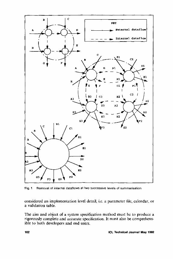
Fig. 1 Removal of internal dataflows at two successive levels of summarisation
considered an implementation level detail, i.e. a parameter file, calendar, or a validation table.
The aim and object of a system specification method must be to produce a rigorously complete and accurate specification. It must also be comprehensible to both developers and end users.
162 ICL Technical Journal May 1992

Fig. 2 Reduction of external dataflows using levelling equations
The simple interface between programming modules encouraged by structured programming contributes to the reliability and maintainability of well structured programs. Some programming languages, as for example ADA, dictate a rigorous interface for procedure calls. Assembler level languages do not enforce structured constructs or module interfaces. However assembler programs can be well structured if they are decomposed into subroutines with simple interfaces.
1CL Technical Journal May 1992 163
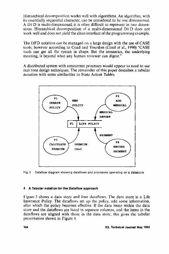
Hierarchical decomposition works well with algorithms. An algorithm, with its essentially sequential character, can be considered to be one dimensional. A DFD is multi-dimensional; it is often difficult to represent in two dimensions. Hierarchical decomposition of a multi-dimensional DFD does not work well and does not yield the clean interface of the programming example.
The DFD notation can be managed on a large design with the use of CASE tools; however according to Coad and Yourdon (Coad et al., 1990) “CASE tools can get all the syntax in shape. But the semantics, the underlying meaning, is beyond what any human reviewer can digest.”
A distributed system with concurrent processes would appear to need to use real time design techniques. The remainder of this paper describes a tabular notation with some similarities to State Action Tables.
Fig. 3 Dataflow diagram showing dataflows and processes operating on a datastore
4 A Tabular notation for the Dataflow approach
Figure 3 shows a data store and four dataflows. The data store is a Life Insurance Policy. The dataflows set up the policy, add some information, after which the policy becomes effective. If the data items within the data store and the dataflows are listed in separate columns, and the items in the dataflows are aligned with those in the data store, this gives the tabular presentation shown in Figure 4.
164 ICL Technical Journal May 1992
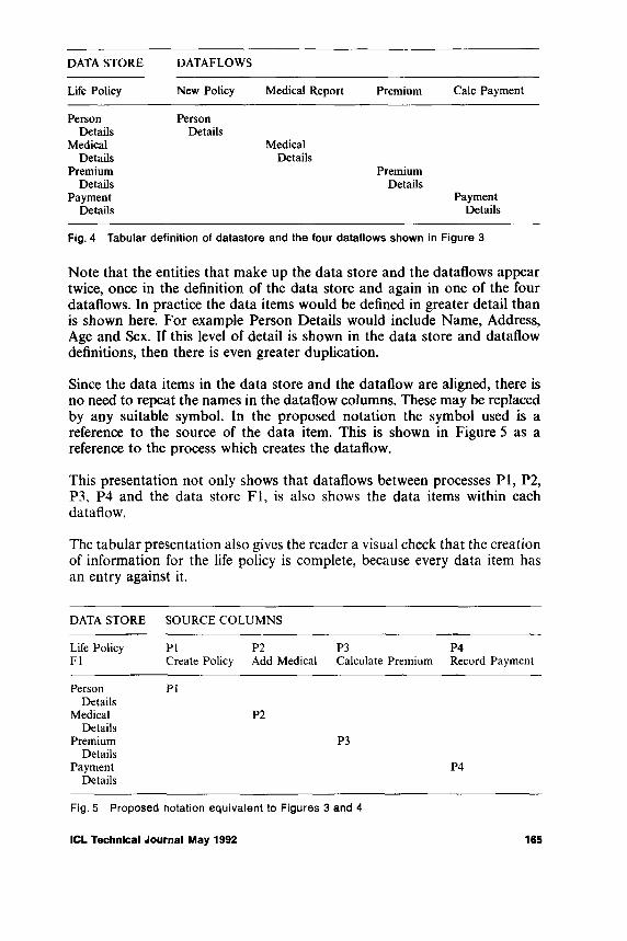
Life Policy New Policy Medical Report Premium Calc Payment
Person PersonDetails Details
Medical MedicalDetails Details
Premium PremiumDetails Details
Payment PaymentDetails Details
Fig. 4 Tabular definition of datastore and the four dataflows shown in Figure 3
Note that the entities that make up the data store and the dataflows appear twice, once in the definition of the data store and again in one of the four dataflows. In practice the data items would be defined in greater detail than is shown here. For example Person Details would include Name, Address, Age and Sex. If this level of detail is shown in the data store and dataflow definitions, then there is even greater duplication.
Since the data items in the data store and the dataflow are aligned, there is no need to repeat the names in the dataflow columns. These may be replaced by any suitable symbol. In the proposed notation the symbol used is a reference to the source of the data item. This is shown in Figure 5 as a reference to the process which creates the dataflow.
This presentation not only shows that dataflows between processes PI, P2, P3, P4 and the data store FI, is also shows the data items within each dataflow.
The tabular presentation also gives the reader a visual check that the creation of information for the life policy is complete, because every data item has an entry against it.
DATA STORE SOURCE COLUMNS
Life Policy PI P2 P3 P4FI Create Policy Add Medical Calculate Premium Record Payment
Person PIDetails
Medical P2Details
Premium P3Details
Payment P4Details
Fig. 5 Proposed notation equivalent to Figures 3 and 4
DATA S T O R E D A TA FLO W S
ICL Technical Journal May 1992 165

Figures 4 and 5 have shown a limited number of high level data attributes in the life policy data store. Additional attributes might be required to show the details of the operator making each entry. This information would almost certainly be required in a practical application for audit purposes, and would not be regarded as implementational detail by an auditor.
Fig. 6 Dataflow diagram with additional dataflows
Figure 6 shows an additional data store F2 which records the operator information at the time of operator log-on. Note the additional dataflows on the diagram. Figure 7 shows the revised definitions of the data store and each dataflow. Note the repetition of operator details four times in the dataflows between F2 and the four processes and again four times in the dataflows between the processes and FI.
The tabular presentation is changed to show the additional attributes as shown in Figure 8.
The four columns remain and correspond to the initial four dataflows between processes PI, P2, P3, P4 and the data store FI. In each case the
166 ICL Technical Journal May 1992

Life Policy New Policy Medical Report Premium Calc Payment
Person PersonDetails Details
Operator OperatorDetails Details
Medical MedicalDetails Details
Operator OperatorDetails Details
Premium PremiumDetails Details
Operator OperatorDetails Details
Payment PaymentDetails Details
Operator OperatorDetails Details
Operator-1 Operator-2 Operator-3 Operator-4
Operator Operator Operator OperatorDetails Details Details Details
Fig. 7 Tabular definition of the life policy datastore and the eight dataflows in Figure 6
DATA STORE SOURCE COLUMNS
Life Policy PI P2 P3 P4FI Create Policy Add Medical Calculate Premium Record Payment
Person PIDetails
Operator F2Details
Medical P2Details
Operator F2Details
Premium P3Details
Operator F2Details
Payment P4Details
Operator F2Details
Fig. 8 Proposed notation equivalent to Figures 6 and 7
DATA S T O R E D A TA FLO W S
ICL Technical Journal May 1992 167
operator details come from the data store F2, hence the entry F2 in each case. The dataflows between F2 and each process are not required.
Again the presentation gives a visual indication that the maintenance of the data on the life policy is complete. Potentially the proposed notation replaces the DFD and the separate definition of evey data flow in a specification; hence it would appear that the notation is more concise than the conventional dataflow notation.
5 Entity States
A life insurance policy does not go into force until it has been through a number of stages or Entity States. The states in the example above are:
• new policy awaiting medical report• part complete awaiting underwriting• part complete awaiting payment of premium• premium paid and in force
These four states correspond directly to the four source columns shown in Figure 8. The addition of State Attributes to the definition of the data store, and the appropriate derivation of these attributes defines the complete cycle of transformations between states.
The notation in Figure 9 shows that a new policy is set up to the Awaiting Medical Report state by the Create Policy process. The Add Medical report process operates if the current state is Await Medical Report, and this process sets the policy into the Await Underwriting state. The example shown has a purely sequential progression through these states. However the progression could be selective or even loop back, as anyone who has allowed his life insurance premium payments to lapse knows.
The representation of a number of different states of a single data entity is referred to as Entity State History. It is an important aspect of analysing data entities. Other notations require separate and additional Entity Life History diagrams (Ashworth, 1989), some use Jackson Structure Diagrams to show sequence, selection and iteration. The tabular notation is more concise than these notations since a single tabular definition shows dataflows and entity history.
Another important benefit of the tabular presentation of entity states is that this is the direct equivalent of the State Action Table which is so important in the analysis and the design of real time event driven systems. Other notations add extra dataflows or Event Flows [Ward et al., 1985] to the basic dataflow notation in order to specify real time systems. The tabular notation is again more concise since it does not need additional dataflows on diagrams or data definitions in data dictionaries.
168 ICL Technical Journal May 1992
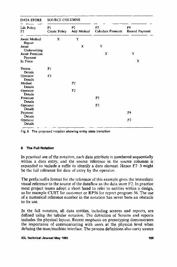
Life Policy PI P2 P3 P4FI Create Policy Add Medical Calculate Premium Record Payment
Await Medical X YReport
Await X YUnderwriting
Await Premium X YPayment
In Force X
Person PIDetails
Operator F2Details
Medical P2Details
Operator F2Details
Premium P3Details
Operator F2Details
Payment P4Details
Operator F2Details
Fig. 9 The proposed notation showing entity state transition
6 The Full Notation
In practical use of the notation, each data attribute is numbered sequentially within a data entry, and the source reference in the source columns is expanded to include a suffix to identify a data element. Hence F2-3 might be the full reference for date of entry by the operator.
The prefix/suffix format for the reference of this example gives the immediate visual reference to the source of the dataflow as the data store F2. In practice most project teams adopt a short hand to refer to entities within a design, as for example CUST for customer or RP56 for report program 56. The use of a numerical reference number in the notation has never been an obstacle to its use.
In the full notation, all data entities, including screens and reports, are defined using the tabular notation. The definition of Screens and reports includes the physical layout. Recent emphasis on prototyping demonstrates the importance of communicating with users at the physical level when defining the man/machine interface. The process definitions also carry source
DATA S T O R E S O U R C E C O L U M N S
ICL Technical Journal May 1992 169
references, hence the full derivation of every data item throughout a system are completely defined.
A single source column and the prefix/suffix notation was originally used in ADS (NCR Corporation, 1970?). The source column was only used on reports and process specifications; the data base was not included. The process specifications were three address instructions.
Instances have been reported (Coad et al., 1990) where design teams have polarised into a Process Specification Team and a Data Base Design Team. As a result both teams go their separate ways.
The tabular notation combines the development of data and process in the same notation. The notation does not preclude an initial data analysis stage complete with full normalisation of the data base. Most experienced designers attempt to understand the data base at an early stage of design. However the notation does encourage the on-going development of the content and access to the data base to be combined with the development of processes which operate on the data.
The notation is a dataflow notation, and therefore works well with distributed systems, both commercial transaction based systems and real time systems. Because it is a dataflow notation it is compatible with, and benefits from the use of dataflow diagrams for planning and communicating with users. However the notation is complete without any diagrams, and hence since it is not dependent on them it is not affected by their limitations.
The objective of the notation is to define a computer system logically and completely, without writing computer programs. The scope and size of the processes should be dictated by the need to be complete and accurate. The processes should not be limited by any implementation constraint of either operating system or batch architecture.
The notation has been fully mechanised. A supporting PC tool produces and maintains all definitions, including graphical diagrams. The diagrams are optional but may be Entity Relationship Diagrams, high level Dataflow Diagrams or State Entity Transition Diagrams. No level balancing is provided, but all entities appearing on a diagram must exist in the design. The tool automates the suffix numbering of data attributes, and effectively removes any need to know the suffix.
The mechanical tool gives all the expected benefits, including multi-user, automatic validation of each entry, automatic version control and publication ready hard copy output.
170 ICL Technical Journal May 1992

7 Practical Experience of the Notation
The notation has been used and refined on many projects over several years. These projects used the notation on a manual basis without a mechanised supporting tool. The projects had an elapsed time of 2 to 3 years, development teams of 30 to 40 staff and produced systems of the order of 1,500,000 lines of 3 GL applications code.
Dataflow diagrams and other graphical notations were used to design the high level shape of these systems; they were also used to give high level management presentations. Hence the supporting tool referred to above also includes facilities to produce diagrams.
The multicolumn entity definition forms were constrained by paper size to hold only 4 source columns. In one case 150 source columns were required for a Nominal Ledger Posting entity. This was simply managed by photocopying the entity definition prior to entering the source column data. The precision and ease of access to this was very important during systems testing of the accounting function.
The notation has also been well received by users, who appear to have little difficulty understanding the specifications after a brief explanation. While management may require the overview and context of a system, supervisory staff at departmental level need to understand the detail, for example how commission is calculated on a customer’s invoice or on the salesman’s commission statement. The notation described in this paper enables the staff to follow the derivation of commission, as it appears on the invoice or the statement, back to the precise calculation via a simple chain of one or more source references.
8 The M ajo r Benefits - A C om plete and Concise Specification
The major benefits of the tabular notation and the PC tool is that completeness of the specification can be checked automatically at any time during the design process. A single report has a bottom line which totals any missing attribute definitions or derivations. No other notation currently has this simple control of accuracy and completeness. Also the reduction in the number of dataflows produces a more concise specification.
References
ASHWORTH, C. SSADM a practical approach. McGraw Hill, 1989.COAD, P. and YOURDON, E. Object-Oriented Analysis. Prentice Hall, 1990.DE MARCO, T. Structured Analysis and System Specification. Yourdon Press, 1979.GANE, C., SARSON, T. Structured Systems Analysis. Prentice Hall, 1979.JACKSON, M. Principles o f Program Design. Academic Press, 1975.KERNIGHAM, B.W. and RICHIE, D.M. The C programming language. Prentice Hall, 1988. MYERS, G.J. Reliable Software Through Composite Design. Van Nostrand Rienhold, 1975. NCR CORPORATION. Accurately Defined Systems. NCR, 1970.
ICL Technical Journal May 1992 171
PAGE-JONES, M., Practical Guide to Structured System Design. Yourdon Press, 1980. WARD, P.T. and MELLOR, S.J. Structured Development for Real-Time Systems. Yourdon
Press, 1985.WARNIER, J.D. Logical Construction o f Programs. H.E. Stenfert Kroese, 1974.WIRTH, N. The programming language PASCAL. Acta Informatica, 1971.YOURDON, E. and CONSTANTINE, L.L. Structured Design. Yourdon Press, 1978.
Biography
M ic h a e l S tu b b s
Michael Stubbs graduated from Trinity College Dublin with a degree in Engineering. His early work involved the development of a software simulator for a new machine. He moved from engineering to software development, where his work included development of assemblers and compilers, and later research into Software Engineering.
He set up a software house operation for a major firm of management consultants, and has since been designing and project managing the development of large commercial systems for consultancies and a computer manufacturer. He is currently a Principal Consultant at Data Sciences.
172 ICL Technical Journal May 1992
Book Review
O pen S y s te m L A N s and the ir g lo b a l in terco n n ec tio n by J. Houldsworth, M. Taylor, K. Caves, A. Flatman, and K. Crook, Butterworth-Heinemann, app 450 pp, ISBN-0 7506-1045-X £25.99This book might more appropriately have been called “Everything you wanted to know about Open System LANs but were afraid to ask!”.
With five co-authors, all prominent in the LAN Standardisation arena, this is by no means a beginners guide to LANs. However, for those readers who have some working knowledge of LANs it is an excellent information source for all of the standardised LANs. Anyone who has ever tried to read one of the LAN standards, to figure out how the LAN is supposed to work, will find this a welcome alternative.
At nearly 450 pages, it is not a book that you will want to sit down and read from cover to cover. Taken a chapter at a time, it is more digestible. I found the attention to detail good, and the style clear, although a little formal. The authors do, occasionally, lapse into “Standardese” with unexplained phrases such as “FIFO”, “Partitioning”, and “Network Service Primitives”, but this doesn’t happen often enough to be a big problem. I was pleased to find that even when reading sections on topics I know well, I learned something. Insights into the history of LANs are also included, helping to explain why LANs are the way they are today.
The book is logically structured, starting with an Introduction to LANs and OSI, and moving progressively up the 7-layer model. Emphasis is placed on the lower four layers of the ISO reference model, with a whole chapter devoted to each. Subsequent chapters deal with Functional Standards and Proprietary Protocols, OSI Management, Structured Cabling, and “The Future”.
The introductory chapter provides a historic background to the development of LANs, WANs and their interconnection.
This is followed by a chapter explaining the principles behind OSI, the Seven Layer Model and the organisations involved in its standardisation. I thought that the way the information from different layers is combined into, say, an 802.3 packet could have been better explained, to show the physical realisation of the 7-layer model, (this omission may be a result of having multiple authors).
ICL Technical Journal May 1992 173
The chapter on LAN standards (by far the longest, at 122 pages) really does explain each of the standardised LANs from first principles. It begins by describing media, encoding techniques, clock recovery, jitter, and environmental considerations before diving into the specifics of each standard. All aspects of 802.3, 802.4, 802.5, and FDDI are covered. Options still under development are also included - the book will need updating in future, as some technical details have changed. Nevertheless, the description of the draft standards as they were in late 1990 is clear and accurate and will certainly aid understanding of the standards when they are published. MAC bridging (transparent bridges, bridge management, source routeing bridges, and source routeing transparent bridges) is also covered in this chapter.
Data Link Control Standards (Layer 2) have their own chapter. Connection mode and connectionless mode services are explained along with HDLC, LAPB, LAPC, LAPD, 8802.2 and their usage for controlling the end to end transmission of information across LANs and WANs.
Network Layer Control Standards (Layer 3) and their structure are explained next, introduced by the ominous phrase “The structure of the standards in the Network Layer is a little tricky to understand.” I agree (I think). The various Layer 3 standards are, however, explained including X.25 and ISO 8473 connectionless mode Network protocol. Router and Frame Relay principles are also explained here.
Transport control standards (Layer 4) come next - ISO 8072 (Connectionmode Transport Service Definition), ISO 8073 (Connection-mode Transport Protocol) and ISO 8602 (Connectionless-mode Transport Protocol) are described and explanations of the various transport classes are given.
“Functional Standards” are recommended combinations of standards from the different ISO layers. Functional Standards for layers 1 to 4 are described here. Also “real world” and proprietary “de-facto” standards such as Novell Netware and TCP/IP are not ignored - although they are not given the level of attention that their current market dominance over their ISO counterparts might warrant.
ISO Network Management is covered from first principles. Todays “real world” standard, SNMP is also described, although again, in less detail.
The relatively new subject of Structured Building Cabling as applied to LANs is explained well, starting with the need for structured cabling systems, going on to explain the mapping of the various standardised LANs onto structured cabling systems and finishing with an overview of current standards activity in this area.
The book finishes up with a crystal ball look into “The Future”. Descriptions of BISDN and ATM, 802.6, Orwell slotted ring, FDDI-II, and CRMA are provided. The chapter ends with the authors view of the future evolution of
174 ICL Technical Journal May 1992

LANs, short term (the next 3-4 years), medium term (5-10 years) and long term (10+ years).
So what does the future hold for LANs and WANs? You’ll have to read it to find out.
Verdict: too heavy for bedtime reading, not suitable for LAN novices, excellent single source LAN reference book.
S teve E v itts
The authors Houldsworth, Flatman and Taylor are with ICL in the UK, Caves is with BNR Europe at Harlow, Essex, UK. and Crook was with ICL for many years.
The reviewer, Steve Evitts, is an independent consultant. The review first appeared in the newsheet “Level 8” from which it is reprinted with by kind permission of the Publishers, Monarch Optical Research, New York, who retain copyright.
ICL Technical Journal May 1992 175

ICL TECHNICAL JOURNAL
G uidance for Authors
1. CO NTEN TThe I C L T e c h n ic a l J o u r n a l has a large international circulation. It publishes papers of high standard having some relevance to ICL’s business, aimed at the general technical community and in particular at ICL’s users and customers. It is intended for readers who have an interest in the information technology field in general but who may not be informed on the aspect covered by a particular paper. To be acceptable, papers on more specialised aspects of design or applications must include some suitable introductory material or reference.
The Journal will usually not reprint papers already published, but this does not necessarily exclude papers presented at conferences. It is not necessary for the material to be entirely new or original. Papers will not reveal m atter relating to unannounced products of any of the ICL G roup companies.
Letters to the Editor and reviews may also be published.
2. AUTHORSWithin the framework defined by §1 the Editor will be happy to consider a paper by any author or group of authors, whether or not an employee of a company in the ICL Group. All papers are judged on their merit, irrespective of origin.
3. LENGTHThere is no fixed upper or lower limit, but a useful working range is 4000-6000 words; it may be difficult to accommodate a long paper in a particular issue. Authors should always keep brevity in mind but should not sacrifice necessary fullness of explanation to this
4. ABSTRACTSAll papers should have an Abstract of not more than 200 words, suitable for the various abstracting journals to use without alteration. The Editor will arrange for each Abstract to be translated into French and German, for publication together with the English original.
5. PRESENTATION5 .1 P r i n t e d ( t y p e d ) c o p yTwo copies of the manuscript, typed l-j/2 spaced on one side only of A4 paper, with right and left margins of a t least 2.5 cms, and the pages numbered in sequence, should be sent to the Editor. Particular care should be taken to ensure that mathematical symbols and expressions, and any special characters such as Greek letters, are clear. Any detailed m athematical treatm ent should be put in an Appendix so that only essential results need be referred to in the text.
5 .2 D ia g r a m sLine diagrams will if necessary be redrawn and professionally lettered for publication, so it is essential that they are clear. Axes of graphs should be labelled with the relevant variables and, where this is desirable, marked off with their values. All diagrams should have a caption and be numbered for reference in the text, and the text marked to show where each should be placed - e.g. “Figure 5 here”. Authors should check that all diagrams are actually referred to in the text and that all diagrams referred to are supplied. Since diagrams are always separated from their text in the production process these should be presented each on a separate sheet and, m o s t im p o r ta n t , each sheet must carry the author's name and the title of the paper. The diagram captions and numbers should be listed on a separate sheet which also should give the au thor’s name and the title of the paper.
5 .3 T a b le sAs with diagrams, these should all be given captions and reference numbers; adequate row and column headings should be given, also the relevant units for all the quantities tabulated. Short tables can be given in the text but long tables are better submitted on separate sheets and these, as for diagrams, must carry the author's name and the title of the paper.
5 .4 P h o to g r a p h sBlack-and-white photographs can be reproduced provided they are of good enough quality; they should be included only very sparingly. Colour reproduction involves an extra and expensive process and will be agreed to only exceptionally.
176 ICL Technical Journal May 1992
5 .5 R e fe r e n c e sAuthors are asked to use the Author/D ate system, in which the author(s) and the date of the publication are given in the text, and all the references are listed in alphabetical order of author at the end. e.g. in the text: further details are given in [Henderson, 1986]”with the corresponding entry in the reference list:
H ENDERSON, P. Functional Programming, Formal Specification and Rapid Prototyping. I E E E T r a n s , o n S o f tw a r e E n g in e e r in g SE-12, 2, 241-250, 1986.
Where there are more than two authors it is usual to give the text reference as “[X et a l ...]”.
Authors should check that all text references are listed, and only text references; references to works not quoted in the text should be listed under a heading such as “Bibliography” or “Further reading”.
5 .6 S t y l eA note is available from the Editor summarising the main points o f style - punctuation, spelling, use of initials and acronyms etc. - preferred for Journal papers.
6. REFEREESThe Editor may refer papers to independent referees for comment. If the referee recommends revisions to the draft the author will be asked to make those revisions. Referees are anonymous. M inor editorial corrections, as for example to conform to the Journal’s general style for spelling or notation, will be made by the Editor.
7. PR O O FS, O FFPR IN T SPrinted proofs are sent to authors for correction before publication. Authors receive 25 offprints of their papers, free of charge, and further copies can be purchased; an order form for copies is sent with the proofs.
8. CO PY RIG H TCopyright in papers published in the I C L T e c h n ic a l J o u r n a l rests with IC L unless specifically agreed otherwise before publication. Publications may be reproduced with the Editor’s permission, which will normally be granted, and with due acknowledgement.
ICL Technical Journal May 1992 177
