i.chem.e. symposium series no. 97 j. h. burgoyne .../media/documents/subject groups...i.chem.e....
TRANSCRIPT
I.CHEM.E. SYMPOSIUM SERIES NO. 97
THE FLASH-BACK HAZARD IN STACKS DISCHARGING FLAMMABLE GASES
J. H. Burgoyne* and R. Fearon**
In the laminar flow of flammable gas mixtures in a tube, the prevention of flash-back depends primarily on establishing a sufficiently large velocity gradient in the boundary layer adjacent to the tube wall. With the onset of turbulent flow in larger tubes however, there appears to be an increasing tendency for flash-back to occur in the core stream and it becomes difficult to state general conditions for its prevention. The problem associated with larger diameter stacks is simplified by the introduction of a perforated plate, for the holes of which the conditions for flash-back can be more reliably predicted, although, for various reasons, the practical testing of a proposed arrangement should usually be considered. Such a device permits economy in the use of diluent gases to render a variable stream "safe" and various aspects of this matter are discussed and illustrated.
Keywords : flammable gases, flash-back, flare-stacks, vent-stacks
INTRODUCTION
The danger of flash-back of flame in flare stacks and in vent stacks discharging flammable gas arises from the possibility that air may be accidentally introduced into the gas stream in some way. It will often have to be assumed that a fuel-air mixture in near-stoichiometric proportions could be formed and that maximum explosive pressures could result from flash-back.
It is clear, in principle, that the danger can be avoided by maintaining a sufficiently rapid flow of gas and the problem is often dismissed with the statement that the velocity of flow of the gas-air mixture must exceed its flame-speed. This guidance is not entirely helpful however because flame speed is not an intrinsic property, but is to some extent dependent upon circumstances other than the nature of the fuel gas.
* Dr. J. H. Burgoyne and Partners ** B.P.International Ltd.
37
I.CHEM.E. SYMPOSIUM SERIES NO. 97
FLASH-BACK PRINCIPLES
Laminar flow
The problem of flash-back was studied with insight several years ago, chiefly in connection with the stability of gas burners and the inter-changeability of burner fuels. For this reason, small bore cylindrical tubes were used preponderently and fully-established laminar flow conditions were adopted. It was concluded that, under these conditions, flash-back occurred most readily in the boundary layer adjacent to the wall of the tube. The condition for the avoidance of flash-back was the attainment of a critical velocity gradient in this layer (1). Its value depended upon mixture composition but for a given fuel gas, there was a maximum, corresponding to the stoichiometric fuel-air ratio, or nearly so. Published values of critical boundary gradient for flash- back (gLM̂ o f various fuel gases in optimum admixture with air are listed in Table 1 (2) in which are included also maximum values of the normal burning velocity. Since the boundary gradient in laminar flow is related to the mean flow velocity, U, by
U = gL d/8 (1)
where d is the tube diameter, flow velocities for the prevention of flash-back under this flow regime can be calculated from the data of Table 1.
Information on the effect of temperature (3), pressure (4,5) and the addition of diluents (2) (nitrogen and carbon dioxide) on conditions for flash-back in laminar flow have been published.
When Equation (1) is utilised to obtain flash-back velocities for various diameters of tube and Reynolds Numbers (Re) calculated for the flash-back velocities obtained, it is found that Re exceeds the value of 2000 for tubes of greater than about 2.3 cm. for methane, and about 0.4 cm. for hydrogen, these representing respectively the slowest and fastest burning of the gases listed. It is therefore clear that for tubes larger than these, laminar will be giving way to turbulent flow.
Turbulent flow
A laminar boundary layer continues to exist however, even in turbulent flow and it may be that flash-back still depends upon the velocity gradient in this layer, the value of which is given, for Re in excess of 5000, by :
gT = 0.023 Re0'8 U/d (2)
For values of Re between 2000 and 5000 velocity gradients intermediate between gT and gT must be assumed.
38
I.CHEM.E. SYMPOSIUM SERIES NO. 97
R e - a r r a n g e m e n t o f E q u a t i o n (2) g i v e s :
0 . 5 6 0 . 1 1 0 .44 0 . 4 4 UT = g T d u / 0 . 1 2 1 J D (3)
li and j> being viscosity and density of the gas mixture respectively.
It will be noticed that the dependence of U<p on tube diameter in Equation (3) is small, so that, if flame propagation in the laminar boundary layer were critical to flash-back in turbulent flow, little variation in flash-back velocity with diameter would be expected. This is what has been found by some investigators. For instance, Khitrin et al. (3) measured maximum flash-back velocities of about 13 m.s-1 for hydrogen-air mixtures, irrespective of tube diameter up to 6.4 cm. This conclusion is supported by the work of Fine (5). Khitrin (3) states that the same constancy of flash-back velocity with diameter applies to methane-air mixtures, but experimental figures are not given.
Others, however, have not found this constancy with turbulent flow, but instead an increase of flash-back velocity with diameter (6). The evident implication is that flash-back under these conditions does not always occur preferentially in the laminar boundary layer. There are reasons why flash-back against the core flow might become more probable in larger tubes. One is the increase in normal burning velocity that accompanies the onset of turbulence (7). /mother is the possibility that the flame-front tending to propagate against the flow may tilt, so achieving a larger area over which the normal burning velocity can operate, this being accompanied by heating of the tube wall so that propagation even in the boundary layer is favoured (6).
On the whole, these effects might be expected to prevail increasingly with larger tube diameters and it has been suggested, for example, that the critical role of the boundary layer is likely to break down with tubes larger than 10 cm. in diameter.
The conclusion drawn must be that no generalisations can be made about flash-back velocities in large-diameter tubes and that, where turbulent flow is involved, the only values acceptable are those that have been demonstrated clearly and reproducibly with the fuel gas and tube diameter concerned.
This conclusion leads to the thought that protection against flash-back in a large-diameter stack might be more reliably achieved by inserting across the gas flow a perforated plate with holes of such diameter that flash-back through them is limited by boundary velocity gradient criteria. This is not, of course, to suggest that the holes should be so far reduced in size as to quench the flame, as in a conventional flame arrester, since this might create an unacceptable resistance to flow.
39

I.CHEM.E. SYMPOSIUM SERIES NO. 97
APPLICATION
Example of a possible arrangement
By way of illustration, let us consider a stack of large diameter discharging hydrogen. We believe that the flashback velocity resulting from the admission of air to this stack could significantly exceed the value of about 13 m.s found by Khitrin (3) for tubes of smaller diameter. If however, we introduce a plate, perforated with say 1 cm. holes, extending over the whole stack cross-section, we have reasonable confidence that for velocities of the subdivided flow through these holes in excess of 13 m.s~l corresponding to a volumetric flow of 0.00102 m3s-]- per hole, flash-back through the plate would not occur, whatever the proportion of air in the gas stream.
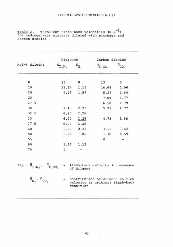
Furthermore the introduction of inert gas (nitrogen or carbon dioxide) into the stream would further reduce the flash-back velocity, by analogy with data for laminar flashback (2). We know that no hydrogen-air mixture containing more than 70 vol.-% of added nitrogen (or 55 vol.-% of added carbon dioxide) is flammable (8). In other words such mixtures have zero flash-back velocity. In Table 2, values are interpolated for maximum flash-back velocities from 0 to 70 vol.-% nitrogen (and 0 to 55 vol.-% carbon dioxide). In each case the contribution of nitrogen (and carbon dioxide) to the flow velocity at the flash-back value is calculated. It emerges that if the flow per (1 cm.) hole due to nitrogen exceeds 2.28 m.s--'- (or for carbon dioxide 1.79 m.s--'-) flashback through the perforated plate should not occur. A basis is therefore available for specifying a perforated plate that will, in co-operation with a fixed supply of nitrogen (or carbon dioxide) less than that necessary to make the stream totally non-flammable, prevent the possibility of flash-back with reasonable certainty.
Data for hydrocarbon fuels
It would be expected that for hydrocarbon streams, the requirements of diluent gases would be less than with hydrogen because of their greater suppressant effect. In the opinion of the authors, however, the published information on flashback in turbulent streams of these fuels is too uncei'tain for any precise specifications to be made. Larger diameter tubes than in the case of hydrogen are necessary to establish turbulence and it seems that the range of conditions in which turbulence is fully-established, but flash-back takes place in the boundary layer, must be much narrowed, if indeed it exists at all.
Bearing these reservations in mind, Table 3 displays relevant data on total extinction limits with nitrogen and carbon dioxide, together with maximum values of critical boundary velocity gradients for flash-back in turbulent flow that are to be found in the literature. These may be applied with caution in the mode of Table 2.
4 0

I.CHEM.E. SYMPOSIUM SERIES NO. 97
Some conditions of design
If the perforated plate method of protection is adopted, three further matters should be considered.
If the plate is placed too far from the open end of the vent pipe, a flash-back may result in significant flame acceleration approaching the plate and a reduction, or even reversal, of flow velocity through it. The plate should therefore be placed not more than two or three diameters from the open end.
By analogy with data for laminar flash-back (3), an increase in temperature will considerably increase the critical boundary velocity gradient in turbulent flow. Flame flashing back through the main stream and stabilising on the perforated plate should not be allowed to remain there, although calculations suggest that the rate of the resultant transfer of heat to the plate is slow, at most. It is however recommended that temperature sensing should be incorporated with the plate so that remedial steps may be taken without undue delay, should flame stabilisation be indicated.
Finally, at the entry of the flow stream to the small holes in the perforated plate flow separation may take place, and a small number of diameters be required for re-attachment(11)Until re-attachment occurs, the boundary velocity distribution, and hence the prospect of flash-back through the hole, would be modified. A certain plate thickness, in relation to hole diameter, is therefore to be recommended.
Conclusion
This paper seeks to give the best guidance possible on a subject concerning which the existing state of knowledge is far from complete. In many cases, it is evident that practical tests of a proposed arrangement should be undertaken before use.
41

I.CHEM.E. SYMPOSIUM SERIES NO. 97
Table 1. Peak values of the critical boundary velocity gradient (laminar flow) and laminar burning velocity for fuel-air mixtures at normal temperature and pressure.
Fuel gas g (s ) Su
Methane 4 00 4 5
Ethane 650 47
Propane 580 48
Ethylene 1400 70
Propylene 800 72
Benzene 720 45
Hydrogen 10 500 32 5
Carbon monoxide 1500 (1) 52
[1) The value for carbon monoxide is in the presence of moisture or other hydrogen-containing fuels, even in small amount. For pure, dry carbon monoxide, gj4 = 100 sec~l, but this is more of academic than industrial significance.
*LM(S"
400
650
580
1400
800
720
10500
1500
-1)
(1)
42
I.CHEM.E. SYMPOSIUM SERIES NO. 97
Table 2. Turbulent flash-back velocities (m.s- ) for hydrogen-air mixtures diluted with nitrogen and carbon dioxide
Nitrogen Carbon dioxide
Mol-% diluent ^ U ^ ^ S
0
10
20
25
2 7
30
32,
35
37,
4 0
50
55
GO
70
Key : U , U„, = flash-back velocity in presence ' * ' 2 of diluent
13
1 1 . 1 4
9 . 2 9
7 . 4 3
6 . 9 7
6 . 5 0
6 . 0 4
5.57
3.71
1.86 0
0
1.11 1.86
2 . 2 3
2 . 2 6
2 . 2 8
2 .26
2 . 2 3
1 .86
1.12
-
13
1 0 . 6 4
8 . 2 7
7 . 0 9
6 . 5 0
5 . 9 1
4 . 7 3
3 . 5 5
1.18
0
0
1 .06
1 .65
1 .77
1 .79
1 .77
1 . 6 6
1.42
0 . 5 9
-
'CO; UM i u ™ = contribution of diluent to flow
velocity at critical flash-back condition
43

I.CHEM.E. SYMPOSIUM SERIES NO. 97
Table 3. Diluent flammability limits (vol.%) and peak (?) values of critical boundary velocity gradient (turbulent flow) for fuel-air mixtures at normal temperature and pressure
Fuel gas Diluent limits (10) Critical boundary velocity gradient
Natural gas
Propane
Ethylene
(a)
(b)
N2
3"3
42
4y
co2
2 4
29
39
GTM
2200(c)
3000
4500
Tube diam.
(cm)
7.62
1.9
2.54
Ref .
6
5
9
Notes :
(a) Containing several per cent of higher hydrocarbons
(b) In an atmosphere of 20% oxygen, 80% argon
(c) May not be maximum value.
44
I.CHEM.E. SYMPOSIUM SERIES NO. 97
References
(1) Lewis, B. and von Elbe, G. J.Chem.Phys. 11, 75 (1943)
(2) van Krevelen, D. W. and Chermin, H. A. G. Seventh Symposium (International) on Combustion 358 (1959)
(3) Khitrin, L. N., Moin, P. B., Smirnov, D. B. and Shevchuk, V. U. Tenth Symposium (International) on Combustion 1285 (1965)
(4) Fine, B. Nat.Adv.Comm.Aeronaut. Tech.Note 3833 (1956)
(5) Fine, B. Nat.Adv.Comm.Aeronaut. Tech.Note 3977 (1957)
(6) Grumer, J. Jet Propulsion 2j3, 756 (1958)
(7) Abdel-Gayed, R. G. and Bradley, D. Phil. Trans. Roy. Soc. London A301, 1 (1981)
(8) Jones, G. W. and Perrott, G. St. J. Ind. Eng. Chem. 3J3, 985 (1927)
(9) Cox, R. W. British Gas, Midlands Research Station. Private communication
(10) Zabetakis, M. G. US Dept. Interior, 1965, Bur. Mines, Bulletin 627
(11) Davies, R. M. and Lucas, D. M. Int.J.of Heat Mass Transfer, 13_, 1013 (1970)
46