icelock lanyard 4h 234 - cascade-usa.com compatibilità e la conformità a tali norme sono garantite...
TRANSCRIPT

I n s t r u c t i o n s f o r u s e
Icelock® lanyard 4h 234L-234000
EN – Caution: Össur products and components are designed and tested to ISO 10328. Compatibility and compliance with this standard is achieved only when Össur products and components are used with other recommended Össur or authorized components. If un-usual movement or product wear is detected in a structural part of a prosthesis at any time, the patient should be instructed to immediately discontinue use of the device and consult his/her clinical specialist. This product has been designed and tested based on single patient usage. This device should NOT be used by multiple patients. If any problems occur with the use of this product, immediately contact your medical professional.
DE – Zur Beachtung: Produkte und Bauteile der Firma Össur sind gemäß ISO 10328 entwickelt und getestet. Kompatibilität und Entsprechung gegenüber dieser Norm wird nur erreicht, wenn Produkte und Bauteile der Firma Össur mit anderen empfohlenen Produkten oder ausdrücklich damit kompatiblen Bauteilen verwendet werden. Wird an einem Konstruktionsteil einer Prothese eine unübliche Bewegung oder übermäßiger Produktverschleiß festgestellt, so ist der Patient anzuweisen, das Produkt nicht weiter zu verwenden und Rücksprache mit seinem Arzt oder Orthopädietechniker zu halten. Zur Beachtung: Dieses Produkt ist für die Anwendung bei ein und demselben Patienten vorgesehen und geprüft. Der Einsatz für mehrere Patienten wird nicht empfohlen. Wenn beim Tragen dieses Produkts Probleme auftreten, sofort den Arzt verständigen.
FR – Attention: Les produits et composants Össur sont conçus et testés selon la norme ISO 10328. Compatibilité et le respect de cette norme ne sont obtenus que lorsque des produits et composants Össur sont utilisés avec d’autres composants recommandés par Össur ou autorisés. En cas de mouvement inhabituel ou d‘usure de la partie structurelle d‘une prothèse, le patient doit immédiatement arrêter de l‘utiliser et consulter son spécialiste clinique. Attention: Ce produit a été conçu et testé pour être utilisé par un patient unique et n‘est pas préconisé pour être utilisé par plusieurs patients. En cas de problème lors de l‘utilisation de ce produit, contactez immédiatement un professionnel de santé.
ES – Atención: Los productos y componentes Össur están deseñados y probados según ISO 10328. La compatibilidad y conformidad con este estándar se obtiene sólo si los productos y componentes Össur se utilizan con otros componentes recomendados o autorizados por Össur. Si en cualquier momento se detecta un desplazamiento o desgaste del producto en la estructura de una prótesis, se debe dar instruciones al paciente para cesar de inmediato el uso del dispositivo y que consulte a su especialista clínico. Este producto se ha diseñado y probado para su uso en un paciente único y no se recomienda para el uso de varios pacientes. En caso de que surja algún problema con el uso este producto, póngase inmediatamente en contacto con su especialista clínico.
IT – Avvertenza: I prodotti ed i componenti Össur sono stati progettati e collaudati conformente alle norme ISO 10328. La compatibilità e la conformità a tali norme sono garantite solamente se i prodotti ed I componenti Össur sono utilizzati in combinazione con altri componenti Össur consigliati o altri prodotti autorizzati. Qualora una porzione strutturale della protesi mostri segni di usura anche meccanica, informare l’utente di sospendere immediatamente l’uso della protesi e di consultare il proprio medico specialista. Avvertenza: Questo prodotto è stato progettato e collaudato per essere utilizzato per un singolo paziente e se ne sconsiglia l‘impiego per più pazienti. In caso di problemi durante l‘utilizzo del prodotto, contattare immediatamente il medico di fiducia.
DA – Forsigtig: Össur produkter og -komponenter er udviklet og afprøvet i henhold til ISO 10328 standarden. Kompatibilitet og overensstemmelse med denne standard opnås kun, når Össur produkter og -komponenter anvendes med andre anbefalede Össur komponenter eller andre godkendte komponenter. Hvis der når som helst konstateres en usædvanlig bevægelse eller slitage af produktet i en strukturel del af protesen, skal patienten instrueres til omgående at holde op med at anvende den pågældende protese og kontakte den behandlende kliniske specialist. Forsigtig: Dette produkt er beregnet og afprøvet til at blive brugt af én patient. Det frarådes at bruge produktet til flere patienter. Kontakt din fysioterapeut eller læge, hvis der opstår problemer i forbindelse med anvendelsen af dette produkt.
SV – Var försiktig! Össur-produkter och -komponenter har konstruerats och testats så att de uppfyller kraven i ISO 10328. Kraven i denna standard uppfylls endast när Össur-produkter och –komponenter används med andra rekommenderade Össur-produkter eller andra godkända komponenter. Patienten ska instrueras att omedelbart avbryta användningen av produkten och rådgöra med sin kliniska specialist om han/hon upptäcker en ovanlig rörelse eller slitage på någon av protesens konstruktionsdelar. Var försiktig: Produkten har utformats och testats baserat på användning av en enskild patient och rekommenderas inte för användning av flera patienter. Om det skulle uppstå problem vid användning av produkten ska du omedelbart kontakta din läkare.
NL – Opgelet: Össur producten en onderdelen zijn ontworpen en getest volgens ISO 10328. Compatibiliteit en naleving van deze norm wordt alleen verkregen wanneer Össur producten en onderdelen met andere aanbevolen Össur producten of goedgekeurde onderdelen worden gebruikt. Als de patiënt abnormale beweging of slijtage van een structureel onderdeel van de prothese ontdekt, moet hij/zij het gebruik van het product onmiddellijk staken en contact opnemen met zijn/haar klinisch specialist. Dit product is ontworpen en getest voor eenmalig gebruik. Hergebruik van dit product wordt afgeraden. Neem bij problemen met dit product contact op met uw medische zorgverlener.
PT – Atenção: Os produtos e componentes da Össur são fabricados e testados de acordo com as normas ISO 10328. A compatibilidade e a conformidade com estas normas apenas são alcançadas se os produtos e componentes da Össur forem utilizados com outras peças recomendadas ou autorizadas pela Össur. Caso seja detectado um movimento pouco habitual ou desgaste do produto na estrutura de uma prótese em qualquer momento, o paciente deve ser instruído a suspender de imediato a utilização do dispositivo e consultar o seu especialista clínico. Este produto foi fabricado e testado com base na utilização por um único paciente e não está recomendado para utilização em múltiplos pacientes. Caso ocorra algum problema com a utilização deste produto, entre imediatamente em contacto com o seu especialista clínico.
日本語 注意:�オズール製品は ISO10328 に準拠するよう設計され、検査されています。この規格の適合性及び準拠性は、オズール製品が他のオズール製品または ISO10328 に準拠した製品と共に使用された場合にのみ有効です。装具の構造部品に異常な動作や摩耗がみられたときはいつでも、装具の使用を直ちに中止し、かかりつけの医師や臨床専門家に連絡するよう患者に指示してください。�本品は患者 1人のみの使用を想定して設計ならびに試験されています。複数の患者に使い回ししないようにしてください。本品の使用に伴って問題が発生したときは、直ちにかかりつけの医師や医療従事者に連絡してください。
中文 – 注意: Össur 产品和部件系依据 ISO 10328 标准设计和测试。Össur 产品和部件只有在与推荐的 Össur 部件或经过认可的部件一起使用时才能保证与此标准兼容,并符合此标准的要求。 任何时候如果发现假体的结构部件出现不正常的移位或磨损,应立即告知患者停止使用本设备并咨询其临床医生。本产品经过设计和测试,供单个患者使用,不推荐用于多个患者。如果您在使用本产品时出现任何问题,请立即联系您的医生。
. . . . . . . . . . . . . . . . . . . . . . . . . . . . . . . . . . . . . . . . 4
Instructions for use . . . . . . . . . . . . . . . . . . . . . . . . . . . . . . . . . . 6
Gebrauchsanweisung . . . . . . . . . . . . . . . . . . . . . . . . . . . . . . . 8
Notice d’utilisation . . . . . . . . . . . . . . . . . . . . . . . . . . . . . . . . . 10
Instrucciones para el uso . . . . . . . . . . . . . . . . . . . . . . . . . . . 12
Istruzioni per l’uso . . . . . . . . . . . . . . . . . . . . . . . . . . . . . . . . . 14
Brugsanvisning . . . . . . . . . . . . . . . . . . . . . . . . . . . . . . . . . . . . . 16
Bruksanvisning . . . . . . . . . . . . . . . . . . . . . . . . . . . . . . . . . . . . . 18
Bruksanvisning . . . . . . . . . . . . . . . . . . . . . . . . . . . . . . . . . . . . . 20
Instruções de Utilização . . . . . . . . . . . . . . . . . . . . . . . . . . . . 22
EN
DE
FR
ES
IT
DA
SV
NL
PT

4
7
8
9
10
11
12
13 14
15
16
17 18
19
20
21
22
23
AP/ML
A
AP/ML
B
C
6
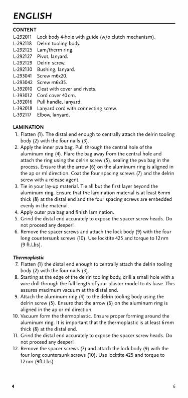
ENGLISHCONTENTL-292011 Lock body 4-hole with guide (w/o clutch mechanism).L-292118 Delrin tooling body.L-292125 Lam/therm ring.L-292127 Pivot, lanyard.L-292129 Delrin screw.L-292130 Bushing, lanyard.L-293041 Screw m6x20.L-293042 Screw m6x35.L-392010 Cleat with cover and rivets.L-393012 Cord cover 40 cm.L-392016 Pull handle, lanyard.L-392018 Lanyard cord with connecting screw.L-392117 Elbow, lanyard.
LAMINATION1. Flatten (1). The distal end enough to centrally attach the delrin tooling
body (2) with the four nails (3).2. Apply the inner pva bag. Pull through the central hole of the
aluminum ring (4). Flare the bag away from the central hole and attach the ring using the delrin screw (5), sealing the pva bag in the process. Ensure that the arrow (6) on the aluminum ring is aligned in the ap or ml direction. Coat the four spacing screws (7) and the delrin screw with a release agent.
3. Tie in your lay-up material. Tie all but the first layer beyond the aluminum ring. Ensure that the lamination material is at least 6 mm thick (8) at the distal end and the four spacing screws are embedded evenly in the material.
4. Apply outer pva bag and finish lamination.5. Grind the distal end accurately to expose the spacer screw heads. Do
not proceed any deeper!6. Remove the spacer screws and attach the lock body (9) with the four
long countersunk screws (10). Use locktite 425 and torque to 12 nm (9 ft.Lbs).
Thermoplastic7. Flatten (1) the distal end enough to centrally attach the delrin tooling
body (2) with the four nails (3).8. Starting at the edge of the delrin tooling body, drill a small hole with a
wire drill through the full length of your plaster model to its base. This assures maximum vacuum at the distal end.
9. Attach the aluminum ring (4) to the delrin tooling body using the delrin screw (5). Ensure that the arrow (6) on the aluminum ring is aligned in the ap or ml direction.
10. Vacuum form the thermoplastic. Ensure proper forming around the aluminum ring. It is important that the thermoplastic is at least 6 mm thick (8) at the distal end.
11. Grind the distal end accurately to expose the spacer screw heads. Do not proceed any deeper!
12. Remove the spacer screws (7) and attach the lock body (9) with the four long countersunk screws (10). Use locktite 425 and torque to 12 nm (9ft.Lbs)

7
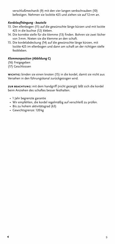
Lanyard components13. Shorten the elbow (11) to the desired length and glue it into the
bushing (12) with loctite 425.14. Find the correct positioning for the cleat (13), drill two 3 mm (1/8ó)
holes, and rivet it to the socket.15. Trim the cord cover (14) to the desired length. Glue it into the elbow
with loctite 425 and to the socket in the correct location.
Cleat positioning (Figure C) (16) Released (17) Locked
important: tie a knot in (15) the lanyard cord to stop it from inadvertently being pulled into the channel.
note: the pull handle (not shown in diagram) can be used for getting a more secure grip on the lanyard cord when the socket is donned.
• 1 Year limited warranty• It is recommended that the lanyard cord be regularly checked
for wear.• Rated up to high activity level (k3)• Weight limit: 120 kg (265 lbs)
8
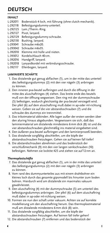
DEUTSCHINHALTL-292011 Bodenstück 4-loch, mit führung (ohne clutch-mechanik).L-292118 Befestigungsdummy-unterteil.L-292125 Lam./Therm.-Ring.L-292127 Pivot, lanyard.L-292129 Befestigungsdummy-schraube.L-292130 Bushing, lanyard.L-293041 Schraube m6x20.L-293042 Schraube m6x35.L-392010 Klemme mit hülle und nieten.L-393012 Kordelschlauch 40 cm.L-392016 Handgriff, lanyard.L-392018 Lanyardkordel mit verbindungsschraube.L-392117 Ellenbogen, lanyard.
LAMINIERTE SCHÄFTE1. Das distalende gut genug abflachen (1), um in der mitte das unterteil
des befestigungsdummys (2) mit den vier nägeln (3) anbringen zu können.
2. Den inneren pva-beutel aufbringen und durch die öffnung in der mitte des aluschaftringes (4) ziehen. Das breite ende des beutels muß von der öffnung wegweisen. Den ring mit der dummyschraube (5) befestigen, wodurch gleichzeitig der pva-beutel versiegelt wird. Der pfeil (6) auf dem aluschaftring muß dabei in ap-oder ml-richtung weisen. Geben sie auf die vier abstandsschrauben (7) und die schraube des dummys ein trennmittel.
3. Das trikotmaterial abbinden. Alle lagen außer der ersten werden über den aluring hinaus abgebunden. Vergewissern sie sich, daß das laminiermaterial am distalende mindestens 6 mm dick (8) ist und die vier abstandsschrauben gleichmäßig ins material eingebettet sind.
4. Den äußeren pva-beutel aufbringen und den laminierprozeß beenden.5. Das distalende sorgfältig abschleifen, um die köpfe der
abstandsschrauben freizulegen. Gehen sie auf keinen fall tiefer!6. Die abstandschrauben abnehmen und das bodenstück der
verschlußmechanik (9) mit den vier langen senkschrauben (10) befestigen. Nehmen sie locktite 425 und ziehen sie auf 12 nm an.
Thermoplastschäfte7. Das distalende gut genug abflachen (1), um in der mitte das unterteil
des befestigungsdummys (2) mit den vier nägeln (3) anbringen zu können.
8. Vom rand des dummyunterteiles aus mit einem drahtbohrer ein kleines loch durch das gesamte gipsmodell bis hinunter zum boden bohren. Hierdurch wird am distalende ein maximales vakuum gewährleistet.
9. Den aluschaftring (4) mit der dummyschraube (5) am unterteil des befestigungsdummys anbringen. Der pfeil (6) auf dem aluschaftring muß dabei in ap-oder ml-richtung weisen.
10. Formen sie nun den schaft unter vakuum. Achten sie auf korrekte modellierung um den aluschaftring herum. Das thermoplastmaterial muß am distalende mindestens 6 mm dick (8) sein.
11. Das distalende sorgfältig abschleifen, um die köpfe der abstandsschrauben freizulegen. Auf keinen fall tiefer gehen!
12. Die abstandschrauben (7) entfernen und das bodenstück der
9
verschlußmechanik (9) mit den vier langen senkschrauben (10) befestigen. Nehmen sie locktite 425 und ziehen sie auf 12 nm an.
Kordelaufhängung - bauteile13. Den ellenbogen (11) auf die gewünschte länge kürzen und mit loctite
425 in die buchse (12) kleben.14. Die korrekte stelle für die klemme (13) finden. Bohren sie zwei löcher
von 3 mm. Nieten sie die klemme an den schaft.15. Die kordelabdeckung (14) auf die gewünschte länge kürzen, mit
loctite 425 im ellenbogen und dann am schaft an der richtigen stelle festkleben.
Klemmenposition (Abbildung C)(16) Freigegeben(17) Geschlossen
wichtig: binden sie einen knoten (15) in die kordel, damit sie nicht aus Versehen in den führungskanal zurückgezogen wird.
zur beachtung: mit dem handgriff (nicht gezeigt) läßt sich die kordel beim Anziehen des schaftes besser festhalten.
• 1 Jahr begrenzte garantie• Wir empfehlen, die kordel regelmäßig auf verschleiß zu prüfen.• Bis zu hohem aktivitätsgrad (k3)• Gewichtsgrenze: 120 kg
10
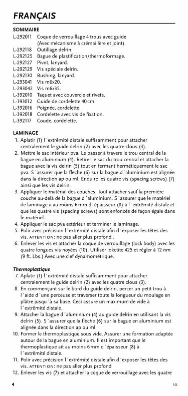
FRANÇAISSOMMAIREL-292011 Coque de verrouillage 4 trous avec guide (Avec mécanisme à crémaillère et joint).L-292118 Outillage delrin.L-292125 Bague de plastification/thermoformage.L-292127 Pivot, lanyard.L-292129 Vis spéciale delrin.L-292130 Bushing, lanyard.L-293041 Vis m6x20.L-293042 Vis m6x35.L-392010 Taquet avec couvercle et rivets.L-393012 Guide de cordelette 40 cm.L-392016 Poignée, cordelette.L-392018 Cordelette avec vis de fixation.L-392117 Coude, cordelette.
LAMINAGE1. Aplatir (1) l´extrêmité distale suffisamment pour attacher
centralement le guide delrin (2) avec les quatre clous (3).2. Mettre le sac intérieur pva. Le passer à travers le trou central de la
bague en aluminium (4). Retirer le sac du trou central et attacher la bague avec la vis delrin (5) tout en fermant hermétiquement le sac pva. S´assurer que la flèche (6) sur la bague d´aluminium est alignée dans la direction ap ou ml. Enduire les quatre vis (spacing screws) (7) ainsi que les vis delrin.
3. Appliquer le matérial des couches. Tout attacher sauf la première couche au-delà de la bague d´aluminium. S´assurer que le matériel de laminage a au moins 6 mm d´épaisseur (8) à l´extrêmité distale et que les quatre vis (spacing screws) sont enfoncés de façon égale dans le matériel.
4. Appliquer le sac pva extérieur et terminer le laminage.5. Polir avec précision l´extrémité distale afin d´exposer les têtes des
vis. attention: ne pas aller plus profond .6. Enlever les vis et attacher la coque de verrouillage (lock body) avec les
quatre longues vis noyées (10). Utiliser lokctite 425 et régler à 12 nm (9 ft. Lbs.) Avec une clef dynamométrique.
Thermoplastique7. Aplatir (1) l´extrêmité distale suffisamment pour attacher
centralement le guide delrin (2) avec les quatre clous (3).8. En commençant sur le bord du guide delrin, percer un petit trou à
l´aide d´une perceuse et traverser toute la longueur du moulage en plâtre jusqu´à sa base. Ceci assure un maximum de vide à l´extrêmité distale.
9. Attacher la bague d´aluminium (4) au guide delrin en utilisant la vis delrin (5). S´assurer que la flèche (6) sur la bague en aluminium est alignée dans la direction ap ou ml.
10. Former le thermoplastique sous vide. Assurer une formation adaptée autour de la bague en aluminium. Il est important que le thermoplastique ait au moins 6 mm d´épaisseur (8) à l´extrêmité distale.
11. Polir avec précision l´extrémité distale afin d´exposer les têtes des vis. attention: ne pas aller plus profond
12. Enlever les vis (7) et attacher la coque de verrouillage avec les quatre

11
vis longues (countersunk screws) (10). Utiliser locktite 425 et régler à 12 nm (9 ft. Lbs.) Avec une clef dynamométrique. (9)
Les composants du lanyard13. Raccourcir le coude (11) à la longueur désirée et le coller dans le
palier (12) avec loctite 425.14. Trouver la position correcte pour l´embout (13), percer deux trous de
3 mm et le riveter à l´emboîture.15. Couper la coque du cordon (14) à la longueur désirée. La coller dans
le coude en utilisant locktite 425 et à l´emboîture dans la position correcte.
Position de barrette (Image C)(16) Débloqué(17) Bloqué
attention: faire un noeud dans (15) le cordon lanyard pour l´empêcher d´être Tiré dans le conduit par inadvertance.
remarque: la poignée de retrait (ne figure pas sur ce diagramme) peut être Utilisée pour obtenir une prise plus sûre du cordon lanyard lorsque l´emboîture Est enfilée.
• Garantie d´un an• Garantie sur le cordon lanyard. On recommande de vérifier
régulièrement l´usage du cordon• Prévu pour un haut niveau d´activité (k3)• Limite de poids: 120 kg (265 lbs)
12
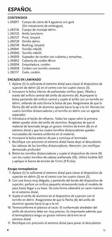
ESPAÑOLCONTENIDOSL-292011 Cuerpo de cierre de 4 agujeros con guía (Sin mecanismo de embrague).L-292118 Cuerpo de montaje delrin.L-292125 Anillo lam/term.L-292127 Pivot, lanyard.L-292129 Ornillo delrin.L-292130 Bushing, lanyard.L-293041 Tornillo m6x20.L-293042 Tornillo m6x35.L-392010 Sujetador de cordón con cubierta y remaches.L-393012 Cubierta de cordón 40 cm L-392016 Empuñadura, cordón.L-392018 Cordón con tornillo conector.L-392117 Codo, cordón.
ENCAJES EN LAMINADO1. Aplane (1) lo suficiente el extremo distal para clavar el dispositivo de
sujeción de delrin (2) en el centro con los cuatro clavos (3).2. Incorpore la bolsa interior de poliacetato vinílico (pav). Pásela a
través del orificio central del anillo de aluminio (4). Acampane la bolsa partiendo del orificio central y sujete el anillo con un tornillo en delrin, sellando de esta forma la bolsa de pav. Asegúrerese de que la flecha (6) del anillo de aluminio apunte hacia la ap o la ml. Revista los cuatro tornillos distanciadores y el tornillo en delrin con un agente separador.
3. Introduzca el tejido de refuerzo. Todas las capas salvo la primera deben quedar atrás del anillo de aluminio. Asegúrese de que el material de laminado tenga un grosor mínimo de 6 mm (8) en el extremo distal y que los cuatro tornillos distanciadores queden incrustados de manera uniforme en el material.
4. Incorpore la bolsa exterior de pav y concluya el laminado.5. Rectifique con precisión el extremo distal hasta dejar al descubierto
las cabezas de los tornillos distanciadores. Atención: ¡no rectifique demasiado profundo!
6. Retire los tornillos distanciadores y sujete el dispositivo de cierre (9) con los cuatro tornillos de cabeza avellanada (10). Utilice locktite 425 y aplique la fuerza de torsión de 12 nm (9 ft.Lbs).
Encajes termoplasticos7. Aplane (1) lo suficiente el extremo distal para clavar el dispositivo de
sujeción en delrin (2) en el centro con los cuatro clavos (3).8. Con una broca muy delgada, y partiendo del borde del dispositivo de
sujeción, perfore un orificio pequeño atravesando todo el modelo de yeso hasta llegar a su base. De esta forma obtendrá un vacío máximo en el extremo distal.
9. Sujete el anillo de aluminio en el dispositivo de sujeción con el tornillo en delrin. Asegúrerese de que la flecha (6) del anillo de aluminio apunte hacia la ap o la ml.
10. Termoconforme el plástico al vacío. El conformado alrededor del anillo de aluminio debe ser muy preciso. Es importante además que el termoplástico tengo un grosor mínimo de 6 mm en el extremo distal
11. Rectifique con precisión el extremo distal para poner al descubierto

13
las cabezas de los tornillos distanciadores. Atencion: ¡no rectifique demasiado profundo!
12. Retire los tornillos distanciadores y sujete el dispositivo de cierre (9) con los cuatro tornillos de cabeza avellanada (10). Utilice locktite 425 y aplique la fuerza de torsión de 12 nm (9 ft.Lbs).
Componentes de la cuerda lanyard13. Corte el codo (11) hasta obtener la longitud deseada y péguelo en el
manguito (12) con loctite 425.14. Determine la ubicación adecuada de la abrazadera (13), perfore dos
orificios de 3 mm y remáchela en el encaje.15. Recorte el revestimiento de la cuerda (14) a la talla deseada. Péguela
con loctite 425 en su posición correcta, tanto en el codo como en el encaje.
Posicion de la abrazadera (Gráf ico C) (16) Desbloqueada (17) Bloqueada
importante: haga un nudo (15) en la cuerda para evitar que se deslice por el Conducto sin que usted se dé cuenta.
atención: puede utilizar la asidera (no figura en el diagrama) a fin de agarrar con Mayor firmeza la cuerda al armar el encaje.
• Garantía limitada de un año.• Se recomienda controlar en intervalos regulares el grado de desgaste
de la cuerda lanyard.• Apto hasta para elevados niveles de actividad (k3)• Peso límite: 120 kg (265 lbs)

14
ITALIANOCONTENUTOL-292011 Unità di chiusura 4-fori con guida (senza meccanismo di innesto).L-292118 Unità utensile delrin.L-292125 Anello di laminazione/termoplastico (lam/term).L-292127 Pivot, lanyard.L-292129 Vite delrin.L-292130 Bushing, lanyard.L-293041 Vite m6x20.L-293042 Vite m6x35.L-392010 Bietta con fodera e rivetti.L-393012 Fodera di corda 40 cm.L-392016 Maniglia di tiraggio, corda lanyard.L-392018 Corda lanyard con vite di connessione.L-392117 Gomito, corda lanyard.
LAMINAZIONE1. Appiattire (1) l’estremità distale abbastanza da permettere di
attaccare al centro il corpo delrin (2) con i quattro chiodi (3).2. Applicare la sacca interna pva. Tirare attraverso il foro centrale
dell’anello di alluminio (4). Allargare la sacca dal foro centrale e attaccare l’anello usando la vite delrin (5), sigillando la sacca pva durante questa operazione. Assicurarsi che la freccia (6) sull’anello di alluminio sia posizionata in direzione ap o ml. Ricoprire le quattro viti distanziatrici (7) e la vite delrin con un agente di sgancio.
3. Legare il materiale accumulato. Legarlo tutto, tranne il primo strato, oltre l’anello di alluminio. Assicurarsi che il materiale laminato sia spesso perlomeno 6 mm (8) all’estremità distale e che le quattro viti distanziatrici siano collocate in modo uniforme nel materiale.
4. Applicare la sacca esterna pva e finire la laminazione.5. Stringere con attenzione l’estremità distale fino a mostrare la
capocchia delle viti distanziatrici. Non andare più in profondità!6. Rimuovere le viti distanziatrici e attaccare il corpo di chiusura (9) con
le quattro viti lunghe svasate (10). Usare la locktite 425 e avvitarle fino a 12 nm (9ft.Lbs).
Termoplastica7. Appiattire (1) l’estremità distale abbastanza da permettere di
attaccare al centro il corpo delrin (2) con i quattro chiodi (3).8. Partendo dal bordo del corpo delrin, fare un piccolo foro con un
trapano per l’intera lunghezza del vostro calco fino alla base. Questo consente il massimo spazio all’estremità distale.
9. Attaccare l’anello di alluminio (4) al corpo delrin usando la vite delrin (5). Assicurarsi che la freccia (6) sull’anello di alluminio sia posizionata in direzione ap o ml.
10. Formare la termoplastica a sottovuoto. Assicurare un’adeguata formazione intorno all’anello di alluminio. E’ importante che la termoplastica sia spessa perlomeno 6 mm (8) all’estremità distale.
11. Stringere con attenzione l’estremità distale fino a mostrare la capocchia delle viti distanziatrici. Non andare più in profondità!
12. Rimuovere le viti distanziatrici (7) e attaccare il corpo di chiusura (9) con le 4 viti lunghe svasate (10). Usare la locktite 425 e avvitarle fino a 12 nm (9ft.Lbs).

15
Componenti lanyard13. Accorciare il gomito (11) per ottenere la lunghezza desiderata e
incollarlo nella boccola (12) con la locktite 425.14. Trovata la posizione corretta per la bietta (13), trapanare due fori di
3 mm (1/8”) e rivettarla alla cuffia.15. Tagliare la fodera della corda (14) alla lunghezza desiderata. Incollarla
al gomito e alla cuffia nella posizione corretta, usando la locktite 425.
Posizionamento dell’asta di rinforzo (Figura C)(16) Sbloccata (17) Chiusa
importante: fare un nodo nel (15) cordone lanyard per evitare cheInavvertitamente venga spinto dentro il canale.
avviso: si può adoperare una maniglia di tiraggio (non visibile nel diagramma) Per ottenere una presa più sicura nel cordone lanyard, quando si infila la cuffia.
• 1 Anno di garanzia (limitata)• Si raccomanda di verificare regolarmente il cordone lanyard per
controllarne l’usura.• Livello di attività fino a “alto” (k3)• Limite di peso: 120 kg (265 lbs)
16
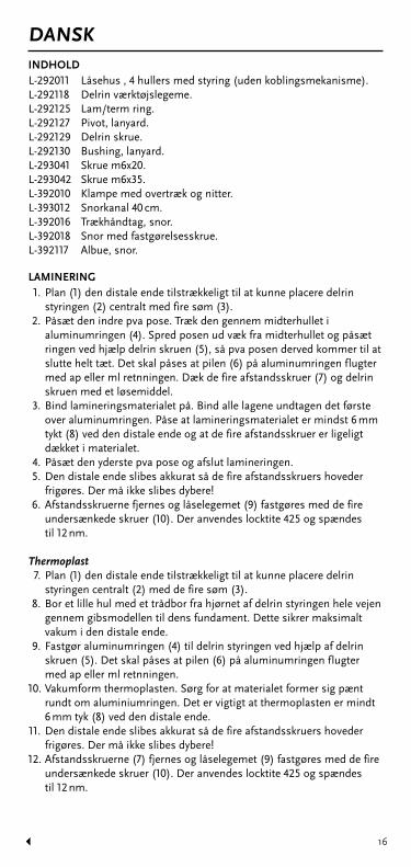
DANSKINDHOLDL-292011 Låsehus , 4 hullers med styring (uden koblingsmekanisme).L-292118 Delrin værktøjslegeme.L-292125 Lam/term ring.L-292127 Pivot, lanyard.L-292129 Delrin skrue.L-292130 Bushing, lanyard.L-293041 Skrue m6x20.L-293042 Skrue m6x35.L-392010 Klampe med overtræk og nitter.L-393012 Snorkanal 40 cm.L-392016 Trækhåndtag, snor.L-392018 Snor med fastgørelsesskrue.L-392117 Albue, snor.
LAMINERING1. Plan (1) den distale ende tilstrækkeligt til at kunne placere delrin
styringen (2) centralt med fire søm (3).2. Påsæt den indre pva pose. Træk den gennem midterhullet i
aluminumringen (4). Spred posen ud væk fra midterhullet og påsæt ringen ved hjælp delrin skruen (5), så pva posen derved kommer til at slutte helt tæt. Det skal påses at pilen (6) på aluminumringen flugter med ap eller ml retnningen. Dæk de fire afstandsskruer (7) og delrin skruen med et løsemiddel.
3. Bind lamineringsmaterialet på. Bind alle lagene undtagen det første over aluminumringen. Påse at lamineringsmaterialet er mindst 6 mm tykt (8) ved den distale ende og at de fire afstandsskruer er ligeligt dækket i materialet.
4. Påsæt den yderste pva pose og afslut lamineringen.5. Den distale ende slibes akkurat så de fire afstandsskruers hoveder
frigøres. Der må ikke slibes dybere!6. Afstandsskruerne fjernes og låselegemet (9) fastgøres med de fire
undersænkede skruer (10). Der anvendes locktite 425 og spændes til 12 nm.
Thermoplast7. Plan (1) den distale ende tilstrækkeligt til at kunne placere delrin
styringen centralt (2) med de fire søm (3).8. Bor et lille hul med et trådbor fra hjørnet af delrin styringen hele vejen
gennem gibsmodellen til dens fundament. Dette sikrer maksimalt vakum i den distale ende.
9. Fastgør aluminumringen (4) til delrin styringen ved hjælp af delrin skruen (5). Det skal påses at pilen (6) på aluminumringen flugter med ap eller ml retnningen.
10. Vakumform thermoplasten. Sørg for at materialet former sig pænt rundt om aluminiumringen. Det er vigtigt at thermoplasten er mindt 6 mm tyk (8) ved den distale ende.
11. Den distale ende slibes akkurat så de fire afstandsskruers hoveder frigøres. Der må ikke slibes dybere!
12. Afstandsskruerne (7) fjernes og låselegemet (9) fastgøres med de fire undersænkede skruer (10). Der anvendes locktite 425 og spændes til 12 nm.

17
Lanyard komponenter13. Afkort albuen (11) til ønsket længde og lim den ind i bøsningen (12)
med loctite 425.14. Find den korrekte placering af klampen (13), bor to 3 mm huller og nit
den på hylstret.15. Afpas snorkanalen (14) til ønsket længde. Lim den ind i albuen med
loctite 425 og til hylstret på rette sted.
Placering af linelås (Billede C) (16) Åben (17) Lukket
vigtigt: der knyttes en knude (15) på træksnoren for at forhindre den iUforvarende at blive trukket ind i kanalen.
bemærk: trækhåndtaget (ikke vist) kan benyttes til at opnå et godt greb om Træksnoren når hylstret skal påføres.
• 1 Års begrænset garanti• Det anbefales at lanyard snoren efterses regelmæssigt for slid.• Klassificeret op til højaktivitetsniveau (k3)• Vægtgrænse: 120 kg

18
SVENSKAINNEHÅLLL-292011 Kopplingshus 4-håls (utan kopplingsmekanism).L-292118 Fixtur.L-292125 Adapter för laminering/termoplast.L-292127 Pivot, lanyard.L-292129 Plastskruv.L-292130 Bushing, lanyard.L-293041 Skruv m6x20.L-293042 Skruv m6x35.L-392010 Linfäste med nitar.L-393012 Linstyrning, 40 cm.L-392016 Dragverktyg.L-392018 Lina med kopplingsskruv.L-392117 Styrning.
LAMINERING1. Plana (1) gipsens distala ände tillräckligt för att centralt kunna fästa
fixturen (2) med de 4 spikarna (3).2. Applicera den inre pva-bagen. Dra ut pva-n genom centrumhålet på
aluminiumplattan (4). Vik undan pva-n från hålet och lås plattan på plats med plastskruven (5). Genom att skruva i plastskruven förseglas även pvan. Försäkra dig om att pilen (6) på alu-plattan pekar i ml eller ap riktning. Smörj de 4 distansskruvarna (7) samt plastskruven med släppmedel.
3. Lägg upp armeringsmaterialet och knyt av samtliga lager (utom det första) upp över alu-plattan. Försäkra dig om att lamineringsmaterialet är minst 6 mm tjockt (8) vid den distala änden och att de 4 distansskruvarna är jämnt inbäddade i materialet.
4. Applicera den yttre pva-bagen och avsluta lamineringen.5. Slipa den distala änden noggrant så att distansskruvarnas skallar
exponeras. Slipa inte längre än detta!6. Avlägsna distansskruvarna och fäst kopplingshuset (9) med de långa
försänkta skruvarna (10). Använd locktite 425 och dra till 12 nm.
Termoplast7. Plana (1) gipsens distala ände tillräckligt för att centralt kunna fästa
fixturen (2) med de 4 spikarna (3).8. Med början vid fixturens kant borras ett litet hål med trådborr genom
hela gipsen till dess proximala ände. Detta görs för att säkra optimalt vacuum vid distala änden vid termoformningen.
9. Fäst aluminiumplattan (4) mot fixturen med hjälp av plastskruven (5).Försäkra dig om att pilen (6) på alu-plattan pekar i ml eller ap riktning.
10. Dra termoplasthylsan och vacuumforma. Säkerställ bra formning run t aluplattan. Det är viktigt att termoplasten är minst 6 mm tjock (8) i den distala änden. Vacuum form the thermoplastic. Ensure proper forming around the aluminum ring.
11. Slipa den distala änden noggrant så att distansskruvarnas skallar exponeras. Slipa inte längre än detta!
12. Avlägsna distansskruvarna (7) och fäst kopplingshuset (9) med de 4 långa, försänkta skruvarna (10). Använd locktite 425 och dra till 12 nm.

19
Komponenter för linkoppling13. Korta av linstyrningen (11) ttill önskad längd och limma fast den mot
bussningen (12) med loctite 425.14. Välj position för linlåset (13), borra två 3 mm’s hål, och nita fast
linlåset med bifogade nitar.15. Trimma linstyrningen (14) till önskad längd och limma fast i den
vinklade linstyrningen i önskat läge med loctite 425.
Placering av linlås (Bild C) (16) Öppen (17) Låst
viktigt: slå en knut (15) på linan för att undvika att den av misstag dras ut Genom kanalen.
observera: draghandtaget (ej på bild) kan användas för att få ett bättre grepp på Linan vid påtagning av protesen.
• Ett års begränsad garanti• Vi rekommenderar att linan kontrolleras regelbundet för slitage.• Klassificerad upp till hög aktivitetsnivå (k3).• Weight limit: 120 kg (265 lbs)
20
NEDERLANDSINBEGREPENL-292011 Slot romp, 4-gats, met geleider (zonder koppelingsmechanisme).L-292118 Delrin gereedschap.L-292125 Lam/therm ring.L-292127 Pivot, lanyard.L-292129 Delrin schroef.L-292130 Bushing, lanyard.L-293041 Schroef m6x20.L-293042 Schroef m6x35.L-392010 Klamp met omhulsel en klinknagels.L-393012 Koordomhulsel 40 cm.L-392016 Trekhandvat, koord.L-392018 Koord met bevestigingsschroef.L-392117 Elleboog, koord.
LAMINERING1. Maak het distale einde plat genoeg om het delrin hulpstuk , met de
vier spijkers (3) centraal te bevestigen.2. Doe de binnenste pva zak er in. Trek deze door het centrale gaatje van
de aluminium ring (4). Waaier de zak uit, weg van het centrale gaatje, en maak de ring vast, met gebruik van de delrin schroef (5), waarbij u tegelijkertijd de pva zak afsluit. Verzeker u ervan dat de pijl (6) op de aluminium ring op lijn ligt in de ap of ml richting. Bedek de vier spatiëerschroeven (7) en de delrin schroef met een losmaakmiddel.
3. Maak uw lay-up materiaal vast. Maak alles behalve de eerste laag buiten de aluminium ring vast. Verzeker u ervan dat het laminerings materiaal aan het distale einde tenminste 6 mm dik is (8), en dat de vier spatiëerschroeven gelijkmatig zijn ingebed in het materiaal.
4. Maak de buitenste pva zak vast en maak de laminering af.5. Schaaf het distale einde precies genoeg af om de koppen van de
spatiëerschroeven bloot te leggen. Ga beslist niet dieper!6. Vewijder de spatiëerschroeven en maak het lock body
(sluitingslichaam) (9) vast met de vier lange, verzonken schroeven (10). Gebruik locktite 425 en draai vast tot 12 nm (9 ft.Lbs).
Thermoplastisch7. Maak het distale einde plat genoeg om het delrin hulpstuk met de vier
spijkers (3) centraal te bevestigen.8. Beginnend aan de rand van het delrin hulpstuk, maakt u een klein
gaatje, met een draadboor, door de volle lengte van het plastic model tot aan de basis. Dit zorgt voor een maximaal vacuum aan het distale einde.
9. Maak de aluminium ring (4) vast aan het delrin hulpstuk met gebruik van de delrin schroef (5). Verzeker u ervan dat de pijl (6) op de aluminium ring op lijn ligt in de ap of ml richting.
10. Vacuum-vorm het thermoplastic. Verzeker u ervan dat het correct rondom de aluminium ring gevormd is. Het is belangrijk dat het thermoplastic aan het distale einde tenminste 6 mm dik (8) is.
11. Schaaf het distale einde precies genoeg af om de koppen van de spatiëerschroeven bloot te leggen. Ga beslist niet dieper!
12. Vewijder de spatiëerschroeven en maak het lock body (sluitingslichaam) (9) vast met de vier lange, verzonken schroeven (10). Gebruik locktite 425 en draai vast tot 12 nm (9 ft.Lbs).
21
Lanyard onderdelen13. Verkort de elleboog (11) tot de gewenste lengte en lijm deze in de
voering (12) met locktite 425.14. Zoek de corresponderende positie voor de klamp (13), maak twee
gaatjes van 3 mm (1/8’’) en nagel hem aan de socket vast.15. Verkort het koordomhulsel (14) tot de gewenste lengte. Lijm het in de
elleboog vast met locktite 425, en op de juiste plaats aan de socket.
Plaatsing van de klamp (Afbeelding C)(16) Losgemaakt(17) Gesloten
belangrijk: maak een knoop in (15) het lanyard koord, om te voorkomen dat het Per ongeluk in het kanaal getrokken wordt.
let op: het trekhandvat (niet op de afbeelding getoond) kan gebruikt worden om Een steviger greep op het lanyard koord te krijgen, wanneer de socket aangedaan Wordt.
• 1 Jaar beperkte garantie.• Het wordt aanbevolen dat het lanyard koord regelmatig op slijtage
wordt gecontroleerd.• Geclassificeerd tot een hoog activiteitsniveau (k3)• Gewichtslimiet: 120 kg (265 lbs) oab/15.05.00

22
PORTUGUÊSCONTEÚDOL-292011 Dispositivo de fixação de 4 orifícios, com guia (Sem mecanismo de engate).L-292118 Dispositivo delrin.L-292125 Anilha laminação/termoplástico.L-292127 Pivot, lanyard.L-292129 Parafuso delrin.L-292130 Bushing, lanyard.L-293041 Parafuso m6x20.L-293042 Parafuso m6x35.L-392010 Pinça com cobertura (revestimento) e rebites.L-393012 Revestimento do cordão 40 cm.L-392016 Puxador, cabo.L-392018 Cordão do kit de cabos com parafuso de fixação.L-392117 Cotovelo, cabo.
LAMINAGEM1. Alise (1) a extremidade distal o suficiente para permitir fixar de uma
forma central o corpo do dispositivo delrin (2) com os quatro pregos (3).
2. Aplique o pva interno. Puxe-o através do orifício central da anilha de alumínio (4). Alargue o saco, afastando-o do orifício central e fixe a anilha por meio do parafuso delrin (5), selando simultaneamente o saco de pva. Certifique-se de que a seta (6) na anilha de alumínio está alinhada na direcção ap ou ml. Cubra os quatro parafusos separadores (7) e o parafuso delrin com um agente deslizante.
3. Fixe a malha. Depois da anilha de alumínio, todas as camadas, excepto a primeira, devem ficar fixas. Certifique-se de que o material de laminagem tem pelo menos 6 mm de espessura (8) na extremidade distal, e de que os quatro parafusos separadores se encontram uniformemente introduzidos no material.
4. Aplique o saco exterior de pva e termine a laminagem.5. Rectifique a extremidade distal cuidadosamente, por forma a deixar à
vista a cabeça dos quatro parafusos separadores. Não vá mais além do que isso!
6. Retire os quatro parafusos separadores, e fixe o dispositivo de fixação (9), utilizando os quatro parafusos escareados compridos (10). Aplique locktite 425 e aperte com 12 nm (9 libras/pé).
Termoplástico7. Alise (1) a extremidade distal o suficiente para permitir fixar de uma
forma central o corpo do dispositivo delrin (2) com os quatro pregos (3).
8. Começando na extremidade do corpo do dispositivo delrin, faça um pequeno furo com uma broca de arame através de todo o comprimento do modelo de gesso, até à base do mesmo. Deste modo, assegura-se o máximo de vácuo possível na extremidade distal.
9. Fixe a anilha de alumínio (4) ao corpo do dispositivo delrin utilizando o parafuso delrin (5). Certifique-se de que a seta (6) na anilha de alumínio está alinhada na direcção ap ou ml.
10. Molde o termoplástico a vácuo. Assegure-se de que este fica correctamente moldado à volta da anilha de alumínio. É importante que o termoplástico tenha pelo menos 6 mm de espessura (8) na

23
extremidade distal.11. Rectifique a extremidade distal cuidadosamente, por forma a deixar à
vista a cabeça dos quatro parafusos separadores. Não vá mais além do que isso!
12. Retire os quatro parafusos separadores(7), e fixe o dispositivo de fixação (9), utilizando os quatro parafusos escareados compridos (10). Aplique locktite 425 e aperte com 12 nm (9 libras/pé)
Componentes do kit de cabos13. Corte o canto/cotovelo (11) no comprimento desejado e cole-o ao
casquilho (12) com loctite 425.14. Determine a posição correcta para a braçadeira (13), faça dois furos
de 3 mm (1/8’’), e fixe-a ao encaixe, por rebitagem.15. Corte o revestimento do cordão no comprimento desejado (14).
Cole-o com loctite 425 ao canto/cotovelo e ao encaixe, no sítio certo.
Posição do grampo (Imagem C)(16) Destrancado(17) Trancado
importante: dê um nó no (15) cordão para evitar que deslize inadvertidamente Para dentro do tubo.
nota: a alavanca (não representada no esquema) pode ser utilizada paraAgarrar mais firmemente o cordão quando é colocado o encaixe.
• 1 Ano de garantia limitada• Recomenda-se que seja verificado regularmente, a fim de determinar
se está ou não gasto.• Próprio para aplicação até níveis elevados de actividade (k3).• Limite de peso: 120 kg (265 lbs)
www.ossur.com IFU 0023 Rev. 3©Copyright Össur 2013
Össur Americas Össur Iberia S.A.27051 Towne Centre Drive Calle Caléndula, 93 -Foothill Ranch, CA 92610, USA Miniparc IIITel: +1 (949) 382 3883 Edificio E, Despacho M18Tel: +1 800 233 6263 28109 El Soto de la Moraleja,Fax: +1 800 831 3160 [email protected] Madrid – España
Tel: 00 800 3539 3668Össur Canada Fax: 00 800 3539 3299120-11231 Dyke Road [email protected], BCV7A OA1, Canada Össur NordicTel: +1 604 241 8152 P.O. Box 67Fax: +1 604 241 8153 751 03 Uppsala, Sweden
Tel: +46 1818 2200Össur Europe Fax: +46 1818 2218Ekkersrijt 4106-4114 [email protected]. Box 1205690 AC Son en Breugel Össur Europe BV – ItalyThe Netherlands Via Baroaldi, 29Tel: +800 3539 3668 40054 Budrio, ItalyTel: +31 499 462840 Tel: +39 05169 20852Fax: +31 499 462841 Fax: +39 05169 [email protected] [email protected]
Össur Deutschland GmbH Össur AsiaAugustinusstrasse 11A 2F, W16 B50226 Frechen No. 1801 Hongmei RoadDeutschland 200233, Shanghai, ChinaTel: +49 (0) 2234 6039 102 Tel: +86 21 6127 1700Fax. +49 (0) 2234 6039 101 Fax: +86 21 6127 [email protected] [email protected]
Össur UK Össur Asia-PacificUnit No 1 26 Ross Street,S:Park North ParramattaHamilton Road Sydney NSW, 2152 AustraliaStockport SK1 2AE, UK Tel: +61 2 88382800Tel: +44 (0) 8450 065 065 Fax: +61 2 96305310Fax: +44 (0)161 475 6321 [email protected]@ossur.com
Össur Head Off iceGrjótháls 5110 Reykjavík, IcelandTel: +354 515 1300Fax: +354 515 [email protected]