ice class strengthening of existing reefer vessels trading ...1033509/fulltext01.pdf · ice class...
TRANSCRIPT

Ice Class Strengthening of Existing Reefer Vessels Trading in the Baltic Sea
- A comparative study of ice classifications 1D and 1C
Authors Dennis Bremberg ([email protected])
Sara Högdahl ([email protected])
Supervisor Ivan Stenius
Date 2016-05-02
Kungliga Tekniska Högskolan Centre for Naval Architecture
Bachelor Thesis in Mechanical Engineering SA118X


Abstract
This bachelor thesis strives to perspicuously answer what an ice strengthening of two different existing reefer vessels might mean for operations in the Baltic Sea and illustrate what factors a shipping company needs to consider when initiating such a project. The main purpose is to provide an information basis facilitating the communication between different parties in the shipping industry.
The existing specialized reefer fleet is old and few new ships are being built or commissioned. At the same time, there is an increasing demand of shipping perishables to St. Petersburg, inciting the strengthening of existing ships to meet market demands. The methodology used in this report is a compilation of selective literature research (primarily providing qualitative, secondary data) and a comparative study in which the secondary data is applied on the reefer classes Crown and Family.
While other classification societies are mentioned, this report focuses on Lloyd’s Register and the ice classes 1D and 1C, suitable for very light and light ice conditions and sailing in convoy with icebreaker assistance. Although ice class 1C is designated for tougher ice conditions than 1D, they share many strengthening requirements. Most substantially, the requirements for 1C concerning the forward region and steering arrangements, stipulated by the Swedish Maritime Administration (Swedish: Sjöfartsverket), are also applicable to 1D. The main differences between these classes originate from the expanse of waterline and structural strengthening in the ice belt, propeller and screw shaft requirements and lastly, the requirements concerning machinery layout and engine output.
The results comprise of estimations regarding minimum engine output, ice belt cost, thickness and spread, bow strengthening and a commentary on the remaining requirements that have been omitted in the analysis. Conclusively, depending on the shipping company’s predefined operational and financial goals, the initial choice of class notation should be evident based on the information presented in this report. If, for example, the Crown class is intended for shipping perishable goods to St. Petersburg all year round, the incentives for converting the ship to ice class 1C are strong, due to a higher reliability in ETA. The effects of added weight and higher expenses could however advocate ice class 1D. Similarly, should the Family class only sail sporadically to St. Petersburg, it could be more financially sensible to convert the ship to ice class 1D.

Acknowledgements
This report has received input and valuable feedback from several persons connected to either the KTH or the shipping company Cool Carriers. First of all, this report owes special thanks to our supervisors Ivan Stenius (KTH) and Ralph Mohlin (Cool Carriers), both of whom with patience and good advice have contributed to and overseen the writing of this report. We would also like to thank our course responsible, Karl Garme, for feedback and advice, and lastly, the vice president of the Fleet Department in Cool Carriers, Åke Jonsson.
Division of work
Each author has been equally responsible for the content in this report, meaning that all parts have been read and approved from the other. While we sometimes have taken different rolls, such as investigator, proof-reader or mediator, we ultimately feel responsible and contributory to all parts.

Nomenclature
𝐴𝐴𝑊𝑊𝑊𝑊 Forward waterplane area 𝐴𝐴𝑤𝑤𝑤𝑤𝑤𝑤 Wetted area 𝐵𝐵 Moulded breadth 𝐵𝐵𝐵𝐵 Bureau Veritas 𝐵𝐵𝐵𝐵𝐵𝐵 Ballasted water line 𝐶𝐶1,𝐶𝐶2,𝐶𝐶3,𝐶𝐶4,𝐶𝐶5 Used resistance calculations, given for ice class 1C and above 𝐶𝐶𝜇𝜇 Used in resistance calculations, calculated with formula 𝐶𝐶𝜓𝜓 Used in resistance calculations, calculated with formula 𝐶𝐶𝐵𝐵 Block coefficient 𝐷𝐷 Height of the ship 𝐷𝐷𝐷𝐷 Doubler method (shell plating) 𝐷𝐷𝐷𝐷𝐵𝐵 Det Norske Veritas 𝐷𝐷𝑝𝑝 Propeller diameter 𝐸𝐸𝐸𝐸𝐴𝐴 Estimated time of arrival 𝐹𝐹𝐹𝐹𝐹𝐹𝐶𝐶𝐹𝐹 Finnish-Swedish Ice Class Rules 𝐻𝐻 Design ice thickness 𝐻𝐻0 Ice thickness 𝐻𝐻𝑊𝑊 Used in resistance calculations 𝐻𝐻𝑀𝑀 Used in resistance calculations, given for ice class 1C and above 𝐻𝐻𝑎𝑎𝑎𝑎𝑤𝑤,𝑖𝑖𝑖𝑖𝑤𝑤 𝑏𝑏𝑤𝑤𝑏𝑏𝑤𝑤 Height of ice belt (aft) 𝐻𝐻𝑎𝑎𝑓𝑓𝑓𝑓𝑓𝑓𝑤𝑤,𝑖𝑖𝑖𝑖𝑤𝑤 𝑏𝑏𝑤𝑤𝑏𝑏𝑤𝑤 Height of ice belt (forward) 𝐾𝐾𝑤𝑤 Used in resistance calculations, depends on number of propellers and the
machinery 𝐵𝐵𝑂𝑂𝑂𝑂 Length overall 𝐵𝐵𝑏𝑏𝑓𝑓𝑤𝑤 Length of bow 𝐵𝐵𝑏𝑏𝑝𝑝 Length between perpendiculars 𝐵𝐵𝑓𝑓𝑟𝑟𝑏𝑏𝑤𝑤 Rule length 𝐵𝐵 Length of ship 𝐵𝐵𝐹𝐹𝐵𝐵𝐵𝐵 Lower ice water line 𝐵𝐵𝐵𝐵𝐵𝐵 Loaded water line 𝐵𝐵𝐿𝐿𝐿𝐿𝐿𝐿𝑑𝑑′𝑠𝑠 𝐹𝐹&𝐹𝐹 Lloyd’s Rules and Regulations for the Classification of Ships 𝐷𝐷𝐶𝐶𝐹𝐹 Max. engine output 𝐷𝐷𝐶𝐶𝐹𝐹 Nor. engine output (85% of MCR) 𝑃𝑃0 Minimum engine output 𝑃𝑃0,1𝐶𝐶 Minimum engine output for ice class 1C 𝑃𝑃0,1𝐷𝐷 Minimum engine output for ice class 1D 𝐹𝐹𝐶𝐶𝐶𝐶 Resistance estimated for sailing in channels with brash ice 𝐹𝐹𝐷𝐷 Replacement method (shell plating) 𝐹𝐹𝑅𝑅𝐹𝐹 Return on investment 𝐸𝐸𝑎𝑎𝑎𝑎𝑤𝑤,𝐿𝐿𝐿𝐿𝑊𝑊𝐿𝐿 Aft LIWL draught 𝐸𝐸𝑎𝑎𝑓𝑓𝑤𝑤𝑓𝑓ℎ𝑤𝑤𝑎𝑎𝑤𝑤𝑤𝑤𝑓𝑓 Draught in fresh water (summer) 𝐸𝐸𝑎𝑎𝑓𝑓𝑓𝑓𝑓𝑓𝑤𝑤,𝐿𝐿𝐿𝐿𝑊𝑊𝐿𝐿 Forward LIWL draught 𝐸𝐸𝐶𝐶𝐹𝐹𝐵𝐵 Total cost of steel and work 𝑈𝑈𝑚𝑚𝑎𝑎𝑚𝑚 Maximum trial speed (ship) 𝑈𝑈 Speed (ship) 𝑈𝑈𝐹𝐹𝐵𝐵𝐵𝐵 Upper ice water line 𝑚𝑚𝑖𝑖𝑎𝑎𝑓𝑓𝑐𝑐𝑓𝑓 Deadweight 𝜑𝜑1 Used in resistance calculations, angle in the forward region of the ship (90° for

ships equipped with bulbous bows) 𝜑𝜑2 Used in resistance calculations, vertical rake of the bow at 𝐵𝐵/4 𝛥𝛥 Displacement at UIWL 𝛼𝛼 Used in resistance calculations, horizontal rake of bow at 𝐵𝐵/4 𝜓𝜓 Used in resistance calculations, derived from 𝜑𝜑2 and 𝛼𝛼 * Denotes approximate numbers

Content Introduction ............................................................................................................................................. 1
Objectives and method ....................................................................................................................... 2
Part I ........................................................................................................................................................ 4
1.1. Shipping companies and trade with reefers ........................................................................... 4
1.2. Classification societies and ice classification ........................................................................... 5
1.3. Lloyd’s Register ........................................................................................................................ 5
1.4. Restrictions due to ice severity in the Baltic Sea ..................................................................... 6
1.5. Who pays? ............................................................................................................................... 6
Part II ....................................................................................................................................................... 8
2.1. Operation in Ice ........................................................................................................................... 8
2.1.1. A typical ice strengthened ship compared to a typical ice breaker ................................ 8
2.1.2. Limitations of the ice strengthened ship ......................................................................... 9
2.2. Waterline strengthening ......................................................................................................... 9
2.2.1. Ship regions ..................................................................................................................... 9
2.2.3. Structural framing ......................................................................................................... 10
2.2.4. Stem and bow ................................................................................................................ 11
2.3. Machinery .............................................................................................................................. 12
2.3.1. Engine output ................................................................................................................ 12
2.3.2. Shafts ............................................................................................................................. 12
2.3.3. Propeller ........................................................................................................................ 13
2.3.4. Cooling water and inlets ................................................................................................ 13
2.4. Ballast tanks ........................................................................................................................... 14
2.5. Appendix strengthening ........................................................................................................ 15
2.5.1. Rudder ........................................................................................................................... 15
2.5.2. Bilge Keels ...................................................................................................................... 15
2.6. Summary of ice class requirements ...................................................................................... 15
Part III .................................................................................................................................................... 17
3. Background .................................................................................................................................... 17
3.1. Application of ice class rules ................................................................................................. 18
3.1.1. Waterline strengthening ............................................................................................... 18
3.1.2. Structural framework .................................................................................................... 21
3.1.3. Strengthening of bow .................................................................................................... 21
3.1.4. Installed engine output ................................................................................................. 21
3.1.5. Propeller and shaft ........................................................................................................ 24
3.1.6. Sea inlets........................................................................................................................ 25
3.1.7. Ballast tanks ................................................................................................................... 25
3.2. Summary................................................................................................................................ 26
PART IV .................................................................................................................................................. 27
4. The third iteration ......................................................................................................................... 27
4.1. Strengthening the hull ........................................................................................................... 27
4.2. Ice belt area and volume ....................................................................................................... 28
4.2.1. Method 1 ....................................................................................................................... 29
4.2.2. Method 2 ....................................................................................................................... 30
4.3. Weight and cost of ice belt .................................................................................................... 32
4.4. Summary................................................................................................................................ 33
Discussion .............................................................................................................................................. 34
The issue of target group and comprehensiveness....................................................................... 35
Future work ................................................................................................................................... 35
Conclusions ............................................................................................................................................ 36
Bibliography ........................................................................................................................................... 37

2016-05-02 Bremberg and Högdahl Bachelor Thesis in Mechanical Engineering, SA118X
1
Introduction The international shipping operator Cool Carriers has observed an increasing demand of shipping perishables to St. Petersburg and further recognizes an opportunity of increased reefer traffic during winter time. Normally, reefer vessels do not have the required ice classification for traffic in icy conditions and are thus operationally limited in icy waters (Kurs-PM, 2016).
The Baltic Sea is a comparatively shallow sea which leads to ice forming relatively quickly. Typically, the ice thickness in the Gulf of Finland range from 0.25-0.5 meters wintertime and reaches its maximum thickness during February and Mars (Nationalencyklopedin, u.d.). The conditions for operating in the Baltic Sea are regulated by rules from administrative authorities in surrounding countries. These rules concern ships operating and sailing to ports within respective authority’s jurisdiction (Sjöfartsverket, 1986).
This Bachelor thesis work strives to perspicuously answer what an ice strengthening of a reefer vessel might mean for operations in the Baltic Sea and thereby illustrate what factors the shipping company needs to consider when progressing such a project. This information could, for instance, be valuable when commercial negotiators, on behalf of the operator, are communicating changes such as ice strengthening of existing ships, with shipyards. The rebuilding of an existing reefer vessel is a complex endeavour consisting of several levels of questions needed to be answered. The nature of these questions comprise of economical and practical issues which requires the owner to allocate both time and resources to address, which might take low priority compared to other issues within the business. An initial information basis could in such cases be valuable wherein the practical implications of the undertaking quickly can be reviewed. The ambition with this study is to create such a basis through a compilation of the ice classed reefer’s operational restrictions, that is, information relating to traffic in the Baltic Sea and the ice classes’ respective (service) range, and also to clarify the ice strengthening’s consequence for the reefer’s design.
It would, from a business oriented perspective, also be interesting to investigate the economic implications of the ice strengthening in relation to ETA (estimated time of arrival), since ice strengthening may result in a more reliable traffic during winter time. However, such a question must be preceded by first determining to what extent the scope of this investigation actually could provide relevant information.
Ice strengthening and other modifications of existing ships is not a new phenomenon and has been done times and times again. For example, in a report on the ice strengthening of a hull section on a smaller commuter vessel, issues such as the angularity and reforming of broken ice depending on time are discussed (Berggren & Lindh, 2014). Another report deals with the lengthening of a reefer ship and investigates the cost of modification versus the return on investment (Ericson & Lake, 2014).
The commercial shipping fleet of perishable goods is today dominated by container ships (composing roughly 90% of total cargo capacity) whilst the remaining 10 % constitute of specialized reefer vessels. However, since the number of trips per container generally is fewer than the number of voyages per reefer, the reefer vessels have a higher utilisation ratio of their cargo capacity (Drewry Maritime Research , 2013). Consequently, reefer operations correspond to roughly a third of total transported cargo volume. These reefers differ from other types of ships mainly in their grade of

2016-05-02 Bremberg and Högdahl Bachelor Thesis in Mechanical Engineering, SA118X
2
specialisation. Reefers are able to accurately regulate the atmosphere in their cargo spaces which enable high control of shelf life of products (aging and quality) (Mohlin, 2016).
The reefer vessels are expected to sail during wintertime in convoy with icebreaker assistance (by creating a channel through the ice). The ice classes considered for this purpose are Lloyd’s (the classification society) 1D and 1C, corresponding to light ice conditions. The strengthening necessary to meet the demands on each class require different levels of modification and result in different operational limitations in relation to the ice conditions. Authorities in Sweden and Finland provide icebreaker assistance to ships destined to a harbor in each land respectively. To be entitled icebreaker assistance the ship has to be able to demonstrate an appropriate ice class and sufficient measures corresponding to the current ice conditions (Sjöfartsverket, 1986).
Different regulatory frameworks include varying requirements on what should be observed to be entitled a specific ice class. There are official tables of equivalence that relate different societies to each other and it is possible for ships to change ice class accordingly, provided that good documentation is kept (Transport Safety Agency , 2010). The regulatory framework arguably best suited for sea traffic during icy conditions in the Baltic Sea are the Finnish/Swedish ice class rules, ranging from class III to II, C to A and lastly A to IA super. Class III is assigned to ships with no ice reinforcement at all while class II include ships with steel hulls able to sustain light ice conditions. The Finnish/Swedish ice classes II and IC are entitled icebreaker assistance, and thus correspondingly also Lloyd’s classes 1D and 1C. For classes above IC, the operational limitations decrease whereas IA super normally do not need any assistance at all (Trafiksäkerhetsverket, 2010).
The Baltic Sea Ice Code is a commonly accepted code for areas contiguous to the Baltic Sea (SMHI, 2014). The code details daily restrictions in harbors depending on weather and ice conditions. For instance, a restriction might be that only vessels with an ice class equivalent to or higher than a certain class is entitled icebreaker assistance. Further, the organisation Baltice.org, have a similar system, but with a better coverage of Russian and Estonian harbors.
The purpose of this report is partly to compile existing information regarding ice classes and classification societies and partly to investigate what aspects to take into consideration when a reefer vessel is strengthened to acquire an ice class appropriate for lighter ice conditions (Lloyd’s 1D and 1C). This report also address what the different classification societies are and how they differ internally. By using the general peripheral compilation, it is then possible to make a perspicuous approximation of the magnitude of the relevant measures for converting an existing ship to achieve a certain ice class, and also to compare which one of the notations are the most suitable. The modifications necessary may include or affect hull form, speed, fuel consumption, engine power and reinforcement of appendices (rudder, propellers, etc.).
Objectives and method This report is divided into four parts, each addressing different objectives. While any part is possible to read separately, the report is structured in such a way that its content is best appreciated if read together. The methodology is a compilation of selective literature research (primarily providing qualitative, secondary data) and a comparative study in which the secondary data is applied.
Part I compiles existing information regarding classification societies. It is a compilation of the requirements concerning ships navigating through the Baltic Sea during winter, including a brief account on external factors affecting such operations and the basic workings of the shipping industry.
Part II is a summary of the biggest differences between ice classes concerning ships sailing in the Baltic Sea. This part primarily focuses on ice classes 1D and 1C (Lloyd’s Register).

2016-05-02 Bremberg and Högdahl Bachelor Thesis in Mechanical Engineering, SA118X
3
Part III contains a case study where the information presented in Part II is applied to two existing reefer vessels. In the case study, the ships are hypothetically strengthened to acquire the ice classes 1D and 1C. Some measures and their implications are discussed. Information about the relevant non-ice class reefer vessels is provided by the shipping company Cool Carriers.
Part IV is an additional, in depth, analysis of one of the strengthening measures (waterline strengthening) presented in Part II and applied in Part III, regarding cost and material consumption.

2016-05-02 Bremberg and Högdahl Bachelor Thesis in Mechanical Engineering, SA118X
4
Part I In this part, the reader is introduced to the concepts of classification societies and trade with reefers, as well as a brief dismemberment of the underlying business structure of the shipping industry. Also, some factors presumably affecting the future development of the specialized reefer trade are highlighted.
1.1. Shipping companies and trade with reefers There are many actors within the global shipping market, all of whom have separate needs, resources and operating strategies. For example, there are bigger shipping companies owning and operating entire fleets and smaller companies who hire almost all services, including ships and operators. For a shipping company to be called a “shipping company” it ought to formally own one, or several, of the ships that they are operating. A typical concern of the shipping company is to optimize management issues relating to ship operations, utilisation ratio per ship and generally to avoid and minimize risk of hazard or postponement since everything affecting the ship quickly produces cost. For instance, some of these regular costs come from fuel consumption and maintenance while ship damage generates both repair, overhead, off-hire and personnel costs. The ships themselves also require administration in affair situations, regardless if the affair concerns a lease or if the shipping company is selling or buying a ship. Further, newbuilding is typically a costly affair and the new built ships seldom generate enough excess profit to reach breakeven within the first years (Svensk Sjöfarts Tidning, 2013).
Due to the differences between shipping companies it follows that their spectra of activities varies as well. Normally, a shipping company has personnel within several sections including marketing, ship operations, law, economy as well as a technical section. The size of the last category differs greatly between different companies, but typical activities include planning of loading, newbuilding and inspections of ships (Svensk Sjöfarts Tidning, 2013).
The company behind the inquiry regarding ice classification (Cool Carriers) is a ship operator. Ship operators and ship owners are not necessarily the same. For instance, a ship owner is the legal entity who owns the ship and is registered as such. The ship also constitutes a legal entity in itself. The documents of registration include the name of the vessel, port of registry and information regarding the owner. The ship operator is the legal entity commercially managing the ship (Inchcape Shipping Services (ISS), 2016). In some cases, the ship owner could also be the ship operator. In this particular report, Cool Carriers is the operator of the Crown and Family ships which will be the basis for the case study performed in Part III.
The biggest ship operators in June 2013 were, in descending order and number of specialized reefer ships during that time in parenthesis, Seatrade (77), GreenSea (39), ART/Frigoship (37), Star (33), NYKCool (now Cool Carriers, 24) and Baltic (23). (Drewry Maritime Research , 2013). The mean age of the specialized reefer fleet was 26 years, in 2013. Assuming a scraping age of 35 years, the prognosis for 2016 predicts a diminishment from 600 to 508 specialized reefer vessels. This development, paired with few newbuildings of specialized reefers and the apparent ascension of

2016-05-02 Bremberg and Högdahl Bachelor Thesis in Mechanical Engineering, SA118X
5
container vessels (with a stable mean age of 11 years before 2013) in the same market sector, suggests that the reefer companies are under significant pressure (Drewry Maritime Research , 2013).
1.2. Classification societies and ice classification There are numerous different classes and guidelines for the shipping industry – as of today there are about 70 different classification societies around the world. The main purpose is to make sure that the ship maintains certain quality standards, including almost everything from the layout of the ship to maintenance and inspections. Different classification societies might not share the same priorities or values. In general, ships need to follow both national and international rules and the biggest classification societies have hence joined and created a collaborative organization, called the International Association of Classification Societies (IACS), in an attempt to make agreements of common rules. This reduces the risk of low safety priorities for some authorities while also setting better common standards in favor of the environment. Administrative authorities, insurance companies and cargo owners - all use classification societies as basis for decision (Svensk Sjöfarts Tidning, 2013).
If a ship is damaged, or otherwise does not fulfil the requirements of a certain class, the ship risks losing its classification certificate. The ship owner has a responsibility of reporting possible damage that could influence the ship’s class but in the end it is the classification society that decides whether a ship is allowed a certain classification certificate or not (Svensk Sjöfarts Tidning, 2013).
Ice classes are among the optional classifications and are not compulsory. There may however arise circumstances that exclude ships without, or below, a certain ice class from entering channels or harbors. The reason for this is to ensure the safety and availability of the harbor for other ships (Svensk Sjöfarts Tidning, 2013). Such arrangements apply to several ports in the Baltic Sea, St. Petersburg included. Baltic Sea Ice Code (SMHI, 2014) and Baltice.org provide up to date information about what the current restrictions are in ports and channels around the Baltic Sea. This information changes from day to day according to the current ice conditions and weather, and could mean that only ships with certain ice class and minimum deadweight are allowed ice breaker assistance to some ports (Sjöfartsverket, 1986).
Another argument, and perhaps one of the biggest economic incentives, for ship owners (and specifically the fleet of Cool Carriers) to ice strengthen their ships is the Leonina system, or other, in essence, similar systems (Mohlin, 2016). The system is based on points, similar to a handicap system, where features that enhance the ship’s service capabilities is rewarded with points and consequently heightens the market value of the ship. The system is made to encourage some features of the ship such as speed and container capacity. An additional rewarding feature is, as already mentioned, ice class – where a higher ice class is rewarded with more points.
Since there are so many different classification societies for ships there are also many different corresponding ice classifications with somewhat different requirements. There is, however, some equivalence between ice classes and it is basically possible to change from one classification society to another provided that the requirements are fulfilled and that all the relevant information is included (Transport Safety Agency , 2010).
1.3. Lloyd’s Register One of the previously mentioned societies is Lloyd’s register. Lloyd’s register (LR) is an organisation, historically operating only as a marine classification society, but now functioning within many fields of industry and provides “global engineering, technical and business services” (Lloyd's Register,

2016-05-02 Bremberg and Högdahl Bachelor Thesis in Mechanical Engineering, SA118X
6
2016). This includes providing rules, conducting research and acting as risk consultants, among other things. Their business, comprising maritime rules and regulations, strive towards “improving safety, quality and performance” (Lloyd's Register, 2016).
Lloyd’s ice classification register is closely related to the Finnish-Swedish ice classification system and do in fact share the same requirements for ice class 1C to 1AS (1A Super in the Finnish-Swedish system). They do not, however, share the ice class 1D, which belongs to Lloyd’s register solely. Consequently, Lloyds register pose a rational candidate in the choice of classification system when operating both outside and in the Baltic Sea.
1.4. Restrictions due to ice severity in the Baltic Sea Depending on the severity of the winter, ice conditions will vary accordingly. Data, collected by the Swedish Maritime Administration between 2007 and 2016, show that restrictions usually apply between December and May (see Figure 1). The figure also shows that ships with low ice class are commonly allowed icebreaker assistance when sailing to and from St. Petersburg.
The light grey line in Figure 1, shows the recommended ice class from insurance companies. While the ship is allowed icebreaker assistance even with the lower ice class, it might be wise to investigate any extra insurance costs due to low ice class. Examples of extra costs could be higher harbor fees or potentially bigger expenses if the ship gets damaged.
The original data, which is divided by year and week, was provided by the Swedish Maritime Administration. There are sometimes large differences in ice severity between the years due to variations in weather, and thus the “ideal” ice class can be both below and over the graph.
Figure 1. Statistics showing the average ice class restrictions in the port of St. Petersburg between December and May. The graph is based on data collected between 2007 and 2016. The notations are ice classes from Lloyd’s Register.
1.5. Who pays? Normally, the ship owner pays for modifications meant to increase the ship’s profitability. Such an arrangement is logical, since the owner may increase future revenues from chartering services. Of course, general market supply and demand still apply to the shipping industry, meaning that the ship operators commercially managing the vessel also might pay for such modifications. Since commercial

2016-05-02 Bremberg and Högdahl Bachelor Thesis in Mechanical Engineering, SA118X
7
management include evaluation of market opportunities and, ultimately, the choice of trades, economic incentives might motivate such an investment. Modifications may include enhanced container or crane capacity as well as ice strengthening of the vessel.
To exemplify, the market model for Cool Carriers can be summarized as follows. Cool Carrier operates a number of ships both long and short term. The former ships are placed in the Leonina system and the latter in the time chartering category. Cool Carriers extract an annual percentage from the accumulated revenues within the Leonina system and the remaining funds are distributed to each ship owner respectively, based on their ship’s trade factor. The trade factor determines the relative “trade efficiency” of the ship and is related to its “rank” in the Leonina system.
The question in this case, whether to ice strengthen or not, becomes solely an economical computation. Based on the vessels operational longevity or alternatively, the chartering agreement, the return on investment must fall within this period for the investment to be deemed profitable (with reasonable risk).
Today, the specialized reefer fleet is quite old and few new commissions are being made. On the other hand, the market for container reefers is expanding due to beneficial terms for container logistics, increased cargo segregation and more versatile loading conditions. Any modifications done to ships within the specialized reefer fleet should therefore (arguably) produce a fairly quick return on investment, since large modifications come at a higher risk in a time that might be regarded as the endplay for specialized reefers. This could be an argument for choosing the ice class 1D, since 1C might be too expensive to reach breakeven within a reasonable time. Although, it is possible that the demand for frozen cargo would grow for reefer ships calling port north of St Petersburg as well in the upcoming years, advocating the 1C notation.

2016-05-02 Bremberg and Högdahl Bachelor Thesis in Mechanical Engineering, SA118X
8
Part II In this part, the general requirements and prerequisites for ship operations in ice, according to Lloyd’s Rules and Regulations for the Classification of Ships (Lloyd’s R&R) are presented and discussed. In addition to Lloyd’s R&R, the Swedish Maritime Administration’s Finnish-Swedish Ice Class Rules (FSICR), are referred to in length. The information presented in part II is further implemented in part III, in which a case study is performed using two existing ships as a baseline.
Both Lloyd’s R&R and the Swedish Maritime Administration’s FSICR are more or less reviewable and presumes a certain amount of knowledge of ship constituents, hull structures and nomenclature. In order to facilitate the understanding of these occurrences and create a general overview, which is part of this report’s aim, equations have been largely omitted and other parts have been further explained.
The main focus of part II is to create a general overview to use as a base when comparing ice classes 1D and 1C. Consequently, the requirements of this part cannot be taken as substitute of their source, nor is the compilation by any means complete.
2.1. Operation in Ice Navigation in ice subjects the ship to different loads. These loads are caused by ice pressure on the hull structure and vary along the hull depending on several factors such as variations in ice thickness and density, the direction in which the ship is moving, service speed, etc. Due to the difficulty in predicting these variations the ice load models are semi empirical and based on certain assumptions regarding the nature of ice loads. For instance, it is assumed that the ice contact area is only a fraction of the ice’s thickness (causing higher pressure due to a smaller area of contact). The data preceding these assumptions were gathered through “full scale observations made in the northern Baltic Sea” (Sjöfartsverket, 2012).
The purpose of predicting ice loads and hull behaviour is to provide a foundation from which sufficient actions may be derived when strengthening a ship for ice operations. Because of several reasons, both practical and economical, there is a need for different grades of ice strengthening (Sjöfartsverket, 2012).
2.1.1. A typical ice strengthened ship compared to a typical ice breaker A typical ice strengthened ship has features such as a double hull, thicker plating in the area of the waterline (especially forward) and extra structural framing. Ideally they have a flat hull shape which enables the ship to ride up over the ice. Other reinforcement areas are the rudders and propellers. Ships originally intended for maneuvering in icy conditions are usually strengthened for one-year-old ice of 50 – 100 cm thickness (Molland, 2008).
Compared to a ship with icebreaking capabilities the reinforcements of an ice strengthened ship are relatively light. Typically, icebreakers have additional reinforcement features such as high quality

2016-05-02 Bremberg and Högdahl Bachelor Thesis in Mechanical Engineering, SA118X
9
steel (which remain tough at low temperatures), high power propulsion and special hull paints (Molland, 2008), which prepare the ship for severe ice conditions.
2.1.2. Limitations of the ice strengthened ship The ice strengthened ship is not permitted to operate at a higher draught than the upper ice water line (UIWL) or lower than the lower ice water line (LIWL) during icy conditions. The UIWL and LIWL measure the design draughts for operations requiring ice strengthening and are also referred to as load water line (LWL) and ballasted waterline (BWL), in corresponding order. The UIWL is determined as the maximum fresh load waterline in summer or, if present, the fresh water timber load line in summer. The LIWL is determined as the line between minimum draughts fore and aft. The fore minimum draught is calculated in relation to ice thickness and displacement at maximum ice draught whereas aft minimum draught is determined in regard to proper propeller function. In order to ensure that these draughts are not exceeded, the salt content in the concerned waters need to be observed when loading the ship. The freeboard requirements differ depending on season and navigational conditions (defined for winter, tropical, summer, etc.) in order to ensure safety and intact stability, according to Lloyd’s R&R.
Further, the propeller is required to stay beneath the surface and if possible below the ice as well Special regard needs to be placed on ballast capacity when determining the LIWL (or BWL) draught with respect to propeller conditions. At both UIWL and LIWL draughts it is necessary to determine that sufficient machine power is installed, however, the machine power shall under no circumstance be less than 1000 kW for ice class 1C and higher (Sjöfartsverket, 2012). For ice class 1D there is no numerical predefined minimal requirement beyond an equation discussed in the section 2.3 Machinery. It is stated in Lloyd’s R&R that the ship should adapt an appropriate speed when entering icy waters. For fast ships (ships operating at speeds higher than 15 knots), special consideration is needed to fully adapt an ice class.
2.2. Waterline strengthening Waterline strengthening is a series of measures to reinforce the band, or ice belt zone, around the UIWL and LIWL in the forward, mid and aft region of the ship. The vertical extension of the ice belt zone lies, for ice class 1D and 1C, 0.4 m above UIWL and 0.5 m below LIWL. It should also be noted that sidescuttles cannot be situated within the ice belt and that, in case the weather deck lies below the UIWL, the bulwark needs to be reinforced as well along with any freeing ports (Sjöfartsverket, 2012). Ice class 1D only require strengthening in the forward region whereas all regions need to be addressed for ice class 1C. It is stated in Lloyd’s R&R that the same requirements valid for the forward region of ice class IC FS are applicable for 1D. The notation FS indicate Finnish-Swedish ice class, and the corresponding requirements are provided by the Swedish Maritime Administration or the Finnish Trafi (Lloyd's Register, 2016). Further, additional rules regarding hull requirements applicable to classes 1D and 1C are found in Lloyd’s R&R in Pt 8 Ch 2 section 4 and 6.
2.2.1. Ship regions The division of regions are defined in the Swedish Maritime Administration’s FSICR in section 4.1.1 Regions. The respective regions are defined as follows (Sjöfartsverket, 2012):
“Forward region: from the stem to a line parallel to and 0.04·L aft of the forward borderline of the part of the hull where the waterlines run parallel to the centreline. For ice classes IA Super and IA the overlap over the borderline need not exceed 6 meters, for ice classes IB and IC this overlap need not exceed 5 meters.”

2016-05-02 Bremberg and Högdahl Bachelor Thesis in Mechanical Engineering, SA118X
10
“Midship region: from the aft boundary of the forward region to a line parallel to and 0.04·L aft of the aft borderline of the part of the hull where the waterlines run parallel to the centreline. For ice classes IA Super and IA the overlap over the borderline need not exceed 6 meters, for ice classes IB” and IC this overlap need not exceed 5 meters.” “Aft region: from the aft boundary of the midship region to the stern”.
Figure 2 illustrates the division of regions.
Figure 2. Hatched area highlighting the ice belt and borders marking the division of aft, mid and forward region.
2.2.2. Strengthening requirements for ice classes 1D and 1C
Since the ice class 1D is achieved simply by implementing the rules for 1C in the forward region, steering arrangements and observing some additional rules in Lloyd’s R&R it is easy to compare the implications of each procedure respectively. The measures necessary for strengthening the forward region include additional shell plating and reinforcement of the transverse and longitudinal framing as well as the stem and bulbous bow.
Shell plating is the outermost skin that covers the hull structure. Its function is to transfer external loads, such as sea and ice pressure, to the main structure whilst maintaining watertight integrity. Consequently, if subjected to ice loads, the hull needs to be reinforced with additional plating. By following the calculation procedure described in the Swedish Maritime Administration’s FSICR, the sufficient plate thickness is acquired. Depending on the ship’s structural system (longitudinal or transversal framing) different equations are used. However, both equations rely on existing scantlings, engine power, steel properties and ice pressure (Sjöfartsverket, 2012).
2.2.3. Structural framing The frame is the ship’s inner structure and provides rigidity and the means of structural integrity. The structure is comprised of different frames bound together with longitudinal and transversal members. Framings are either longitudinal, transverse or mixed. The respective requirements for each class include strengthening of the frames in order to withstand additional pressure and loads from navigation in ice. The requirements found in the Swedish Maritime Administration’s FSICR relate to the section modulus of both the main and intermediate frames and, in case of longitudinal framing, shear area as well. The FSICR also covers ice stringer and web frame scantlings. The section modulus is a geometric property that relates cross section to elastic or plastic yielding (Lundh, 2013)].
Firstly, the vertical extension of the ice strengthened frames should, for class 1C and the forward region of a ship with class 1D, stretch from 1.0 m above the UIWL to 1.6 m, in the forward region only, under the LIWL. Further, the downward vertical extension under LIWL is to be 1.3 m (0.3·L abaft from stem), 1.0 m (midship) and 1.0 m (aft). If the reinforcement of a frame should pass a deck or tanktop, by no more than 250 mm, it can be neglected (Sjöfartsverket, 2012).

2016-05-02 Bremberg and Högdahl Bachelor Thesis in Mechanical Engineering, SA118X
11
Secondly, each frame shall, regardless of type of framing, be connected to its supporting structure effectively. Longitudinal frames shall be attached to any structural element it passes with brackets. “Structural elements” include bulkheads and web frames, that is, transverse structures placed in intervals supporting the longitudinal frames. For ships with transverse frames terminating at a deck or stringer, these should be fastened with a bracket or similar construction. It is important to make sure that the brackets are dimensioned according to relevant hull scantlings, that is, fulfilling the requirements on thickness and stiffness (Sjöfartsverket, 2012). Also, as stated in section 4.4.4.1 in the same document, “When a frame is running through the supporting structure, both sides of the web plate of the frame are to be connected to the structure (by direct welding, collar plate or lug)” (Sjöfartsverket, 2012). The upper end of a transverse frame, main or intermediate, should be attached to the deck of an ice stringer (stringers within the ice belt). The lower end should be attached to a stringer, tanktop or deck. For ice class 1C, transverse frames terminating at, below or above the ice belt, should be fastened to adjacent frames by a longitudinal member of the same scantlings as the frame itself. If the frame terminates 1.8 m or higher above the ice belt it does not need to be fastened except in the forward region (Sjöfartsverket, 2012).
Thirdly, frames not perpendicularly fastened to the side shell are to be supported by ice stringers, intercostals, brackets or similar constructions spaced on a distance not exceeding 1300 mm for class 1C (Sjöfartsverket, 2012), and 2000 mm, for class 1D (Lloyd's Register, 2016). This is to prevent tripping of frames which means “the collapse of a frame against the side shell” (Canadian Coast Guard, 2013).
Lastly, there are also demands on the section modulus for stringers, both within and outside the ice belt, acting as support to the ice strengthened frames, which should be adhered. Deck strips serving as ice stringers abreast of hatches need to comply with additional requirements for shear area and section modulus (Sjöfartsverket, 2012).
2.2.4. Stem and bow Both the Crown ship and Family ship are equipped with a bulbous bow, which is common among ships sailing at high speed or having large block coefficients. One argument for fitting a bulbous bow onto the vessel, forward of the collision bulkhead, is to reduce the motion resistance of the ship. There are no specific design rules regarding the shape of a ship’s bow, but generally, it is reinforced with additional shell plating as protection against anchors, chains and ice (Eyres, 2007).
According to Lloyd’s R&R, there should be a suitably tapered transition piece (Lloyd’s, Pt 8, Ch 2, 6.4.4) connecting the keel and the reinforced stem plating if the ship is fitted with a bulbous bow. Basically, the bulb forward of the ship should be fully plated whilst making sure that the reinforced stem plating continues below the Light Ice Waterline for at least 750 mm.
Further strengthening regarding the bulbous bow or stem includes extra vertical stiffeners, which might be needed in order to meet the requirements for the section modulus at the stem. This modulus depends on the shaft power, which is further explained in section 2.3 Machinery.
The maneuvering capabilities in brash ice are higher if the ship has an edged stem. Both ships already have a rather sharp bow since they were built for high service speeds (around 21 knots). By fitting a sharp angled stem at the front of the ship the maneuverability could be even further improved.
To ensure ship safety when sailing in convoy, or towing, it should also be noted that ships of the lower ice class must not be equipped with an ice bow knife, “an extra plate inserted between the stem and the bulbous bow” (Lloyd’s, Pt 8, Ch 2, 2.1.10). The risk for accidents associated with close contact do not permit towing operations at a short distance if a bow knife is implemented.
2016-05-02 Bremberg and Högdahl Bachelor Thesis in Mechanical Engineering, SA118X
12
Regarding the forward region of the ship, there are no apparent differences between ice class 1D and 1C. It is, as mentioned previously, stated in Lloyd’s R&R that the rules for IC FS are fully applicable for Lloyd’s 1C and 1D (in the latter case only for the forward region) as well as for the steering arrangements (Lloyd’s, Pt 8, Ch 2, 1.2.2).
2.3. Machinery The machinery systems onboard a reefer vessel include main engine and auxiliary generators. Due to strict control of cargo atmosphere, temperature and high speed, a lot of power is needed. The power consumption of such a vessel can thus be quite high, leading to a high amount of cooling water. This consequently leads to extra care for anti-freezing arrangements in sea inlets and pipes of the cooling water systems.
Regarding material, all the components of the main propulsion system should be made from an approved, ductile material – in Lloyd’s R&R, steel is recommended. Some strengthening of shafts and propeller blades should be made, according to section 2.3.2 Shafts and 2.3.3 Propeller.
When the propeller strikes ice, the propeller itself and systems connected to it, such as shafts and gears, experience additional loads, referred to as ice torque. When strengthening a ship for navigation in ice, the ice torque constitutes the dimensioning parameter and varies depending on ice class and propeller diameter. The higher the ice class, the larger the ice torque. Should the propellers not be fully submerged when sailing, the factor for ice class 1A applies to both ice class 1B and 1C as well (Lloyd’s R&R).
2.3.1. Engine output The main engine is basically classed according to its maximum output propulsion shaft power¸𝑃𝑃0. There are multiple ways of estimating the minimum value for 𝑃𝑃0, even within the ice classes. It is stated that the maximum output should be at least 1000 kW for ice class 1C, but other calculations based on formulas are needed in order to decide the actual minimum value.
Overall, the calculations for the minimum engine output are significantly simpler for ice class 1D than for ice class 1C, due to the differences in ice conditions. A fixed factor is used for ice class 1D and the only inputs are the breadth of the ship and the rule length (which is usually between 96% and 97% of the extreme length at waterline), resulting in an estimated engine output which is easily calculated.
For ice class 1C the formula gets more complex and it also needs to be done twice to determine the greater minimum engine output for two design draughts. The calculated minimum engine output for ice class 1C does however result in a more exact value due to respect being paid to hull form, ice resistance, propeller type and propeller diameter. The ice resistance formula in FSICR is based on semi empirical models. The formulas are further explained in part III.
2.3.2. Shafts There are several different shafts transferring power between the propeller (outside the hull) and the engine (inside the engine room). The screw shaft and the stern tube are connected directly to the propeller and are thus subjected to ice loads and cold temperatures. For ice class 1D, the diameter of the screw shaft and stern tube need to be strengthened with a 5% thickness increment as defined in Lloyd’s R&R, presuming that the existing machinery system is built according to the class rules for open water service. For ice class 1C, there are a few more parameters to consider, such as tensile strength of the blades and the yield stress of the shaft. Depending on the diameter of the propeller boss, there are two separate ways for calculating the minimum screw shaft diameter. Should this

2016-05-02 Bremberg and Högdahl Bachelor Thesis in Mechanical Engineering, SA118X
13
diameter still be smaller than the class rule diameter, the latter is to be used. Crankshafts1, thrust shafts or intermediate shafts are all inside the ship and do not have to be further strengthened for either notation.
2.3.3. Propeller The propellers will be exposed to low temperatures and possible brash ice. Due to high rotational speed the propeller(s) are thus extra vulnerable and need to be built according to relatively strict guide lines, for example regarding material and blade thickness. The requirements for 1D and 1C differ slightly and are further explained below.
The material used for propellers must show sufficient properties regarding both hardness and elongation. Materials generally have a ductile to brittle transition temperature and some metals could become more fragile (or brittle) as the temperature drops below zero degrees Celsius. Impact tests should thus be performed in -10°C. Copper alloys and cast steel are the approved material groups regarding propellers. The requirements depend on the choice of material since they behave differently to each other (FSICR 3.2).
According to the book Marine Propellers and Propulsion (Carlton, 2012), stainless steel propellers only make up a small part of all propellers classed by Lloyd's Register. Although the choice of material has differed widely over the years, nickel-aluminum seems to be the most popular choice ever since the 1980's. Stainless steel is however often used for ice classed vessels, due to good properties such as toughness and reparability. The possible impacts during sailing in brash ice call for a material that is able to withstand impact damage. Cast steel, which is recommended in Lloyd's R&R, have fairly good tensile properties but the copper-based alloys (such as bronze or brass), which are also recommended, would provide a better resistance to corrosion and erosion.
The main difference between respective notations minimum blade tip thickness is what parameters that are used in the given formulas (Lloyd’s R&R for ice class 1D and FSICR for ice class 1C). Both formulas depend on the minimum tensile strength, 𝜎𝜎𝑟𝑟, of the propeller material. For ice class 1D the minimum blade tip thickness depends on the root thickness of the blade whilst, for ice class 1C, the propeller diameter is included. It is possible that the general class rules (none ice class) require a thicker tip thickness than the ice class rules for 1C. Should this be the case, the thicker measure should be taken.
The leading edge of the propeller blade is naturally the part that is the most exposed to cavitation during service (Carlton, 2012). This, combined with brash ice, calls for some reinforcement regarding minimum blade edge thickness. The rules for deciding the edge thickness of the blades adhere to the minimum propeller blade tip thickness as basis for calculations (Lloyd’s, Ch8, Pt2, 5.5). Ice class 1C follows the same rules for determining the edge thickness as ice class 1D and constitute of a minimum percentage of the blade tip thickness, which is explained above.
There are specific rules regarding keyless propellers (stated in both Lloyd’s and FSICR).
2.3.4. Cooling water and inlets The parts of the ship in need of water inlets and overboard discharge lines are mainly the cooling water system and fire pumps, both of which are explained below.
Cooling water is highly needed for the main and auxiliary machinery systems and strong priority should be given to keep the cooling water inlets and pipes free from ice. There are multiple methods
1 Crankshafts are shafts converting reciprocating motion to rotational motion.

2016-05-02 Bremberg and Högdahl Bachelor Thesis in Mechanical Engineering, SA118X
14
that are acknowledged by the classification societies, including heating coils and alternative placement of water lines.
For ice class 1D it is required that the discharged cooling water is used for warming up the inlet water. This is achieved by fitting connections between the inlet water and the overboard discharge water (Lloyd’s R&R, Ch 8, Pt 2, 5.6.1). It is also stated that the connections for inlet and discharge water to a water box should be led closely to each other to heat exchange between the warm and the cold water.
For ice class 1C, other rules and requirements regarding the cooling water of the ship’s miscellaneous machinery systems are stated in the FSICR. They consist in general of inlet placement, sea chest capacity and placement, and strainer plate area. The details are further explained below.
The placement of the inlets on the reefer vessels must be taken into consideration since the FSICR state that there should be inlets close to the centerline and possibly well aft. The suggested placing seems a bit vaguely phrased, though, and it might not be of biggest importance should the inlets be placed in some other way and appear difficult to move.
The sea chest, through which sea water primarily enters the ship, should be designed having the engine output in mind – the more power, the bigger the chest. One cubic meter per 750 kW engine output is the general recommendation in FSICR. Here, the engine output is defined as the engine output being used while in service. Any difficulties meeting the requirements regarding sea chest volume could be solved by using two smaller chests instead of one big. Heating coils could also be installed in connections to the chests if needed.
In order to prevent ice from clogging the inlet pipes, the chests should be placed at a sufficient level below the ice layer (which, for ice class 1C, is assumed to mostly consist of brash ice and, for ice class 1D, consist of even lighter ice). Low pressure steam or compressed air should be connected to the sea inlets so that the cooling water pipes can be properly cleared. Should steam or compressed air not be an option, there should be other arrangements that enables circulation of ballast water from ballast tanks.
The fire pumps are important and the inlets should naturally avoid getting blocked by accumulated ice. It is therefore important that the fire pumps are connected to inlet suction pipes that fulfill the requirements and that at least one of the pumps onboard are connected to a sea chest following the Finnish-Swedish ice class rules explained above.
2.4. Ballast tanks For both ice class 1D and 1C, it is important to keep the ballast tanks ice free. Specifically concerned are ballast tanks located above the BWL, in case they are needed to achieve a sufficient draught (FS 2.2). Circulating ballast water could be regarded as a complementary arrangement to the cooling water system but may not be regarded as a replacement for the measures relating to the requirements explained in 2.3.4 Cooling Water.
Possible damages from freezing ballast tanks are further explained with examples in Lloyd’s R&R. These examples discuss how pressure from ice, expanding inside pipes and tanks, result in blockage from ice and cracks or leaks (in turn affecting or compromising the hull or engine systems). It is prescribed that such hazards should be prevented with anti-freezing devices such as heating coils, continuous circulation or air bubbling. The ice class requirements regarding ballast tanks can be fulfilled through a demonstration that these dangers are prevented. This could be done by calculations, service experience or experiments.

2016-05-02 Bremberg and Högdahl Bachelor Thesis in Mechanical Engineering, SA118X
15
2.5. Appendix strengthening The different appendices on ships include propeller blades, rudders and bilge keels. These are all extra vulnerable due to possible impacts when sailing in ice infested waters.
2.5.1. Rudder In accordance to Lloyd’s R&R the dimensioning of rudder “scantlings, posts, rudder horns, solepieces, rudder stocks, steering engine and pintles are to be dimensioned in accordance with “Pt 3, Ch 6 Aft End Structure” and “Pt 3, Ch 13 Ship control systems as appropriate”. When determining rudder scantlings the speed for both classes, 1D and 1C, shall be assumed to be no less than 14 knots. If the maximum service speed is higher, this value is used when making the calculations. “The components of the steering gear shall be dimensioned to stand the yield torque of the rudder stock” (Sjöfartsverket, 2012).
The rudder is one of the parts that share the same rules for both ice notations.
2.5.2. Bilge Keels Bilge keels, which are used for reducing rolling movements of the ship, are often easily damaged due to their placement and design. Going in ice infested waters heightens the risk of the bilge keel getting damaged or possibly even completely ripped off. In the Finnish-Swedish ice class rules, it is recommended that the preventative actions focus on keeping the hull intact should the bilge keels be ripped off. This could be done by dividing the bilge keel into several independent sections so that if one section is ripped off the others stay intact. It is also important that the connections to the hull are designed in such a way that the bilge keels could be ripped off without severe damage to the hull itself (FS, 4.9). These rules primarily apply to ships of ice class 1C or higher. In Lloyd’s it is mentioned that ships should not have bilge keels fitted in the forward region of the ship if they are intended to be used in ice. Those ice conditions are however heavier than ships classed 1D or 1C are intended for.
2.6. Summary of ice class requirements There are a lot of similarities between ice class 1D and 1C. As shown earlier in this part of the report, some requirements (especially regarding the forward region, rudder and steering arrangements) are actually the very same for both ice classes.
When strengthening the ship for navigation in ice infested waters, several factors must be regarded. Firstly, in order to choose an appropriate ice class, the range of operation needs to be defined in relation to the incentives for ice strengthening as well as the relevant ice conditions. Depending on ice class, different alterations to the ship will be necessary. In summary of part II, the main differences between ice classes 1D and 1C are compiled below in Table 1.

2016-05-02 Bremberg and Högdahl Bachelor Thesis in Mechanical Engineering, SA118X
16
Table 1. General differences between ice class 1D and 1C.
Ice class 1D 1C Waterline strengthening Forward region. Forward, mid and aft region.
Structural strengthening Forward region. Forward, mid and aft region.
Stem and Bow Amount of material proportional against engine output.
Machinery Should adhere to
• Formula • Class requirement
Chose the highest value
Should adhere to • Minimum requirement • Formula • Class requirement
Chose the highest value Screw Shafts 5 % increment of screw (and
tube) shaft diameter. Separate formulas depending on propeller boss diameter, or possibly diameter according to class rules
Crank-, thrust- and intermediate shafts
Same (no strengthening required)
Material requirements for propeller
Same
Minimum Propeller blade tip thickness
Based on root thickness of the blade and tensile strength of material.
Based on diameter of propeller and tensile strength of material.
Minimum propeller blade edge thickness
Same formula
Cooling water Same
Inlets and Ballast Tanks Same
Appendix strengthening Same
Steering arrangements Same
Bilge keels strengthening Not specified Additional rules

2016-05-02 Bremberg and Högdahl Bachelor Thesis in Mechanical Engineering, SA118X
17
Part III In this part, the information presented in Part II is applied to two existing reefer vessels. The methodology will comprise of sections addressing the topics introduced in the previous part. Ultimately, a comparison between the Crown ship Crown GARNET and Family ship DITLEV Reefer will be made.
3. Background To provide an overview of the ships, some main particulars are presented in Table 2 alongside their general arrangements, shown in Figure 3 and Figure 4. These drawings provide the layout, dimensions and some structural properties. The drawings will also be used to illustrate some of the measures taken in order to achieve each ice class notation.
Figure 3. General arrangement of the Crown ship.
Figure 4. General arrangement of the Family ship (today, DITLEV Reefer).

2016-05-02 Bremberg and Högdahl Bachelor Thesis in Mechanical Engineering, SA118X
18
Table 2. Main particulars for ships.
Entity Symbol Unit Crown Family Deadweight mcargo [ton] 10333 17610
Displacement at UIWL Δ [ton] 16523 25532
Length (O.A) LOA [m] 151.99 164.33
Length (B.P) LBP [m] 139.4 150.60
Breadth (MLD.) B [m] 23 24
Depth (MLD.) D [m] 18.5 15.7
Service speed U [Knt] 21 19
Trial max speed UMax [Knt] 22.61 -
Max. engine output MCR [KW] 11920 11250
Nor. Engine output (85% of MCR)
NCR [KW] 10132 -
Propeller diameter Dp [m] 6.2 5.5
AUX. diesel generator kW 2x500+2x1000 3x1280
3.1. Application of ice class rules In this section, the rules for ice class 1D and 1C are applied to the Crown and Family ships. In some cases, the ship already fulfills the requirements for both classes, meaning that no additional measures are needed.
3.1.1. Waterline strengthening Input data for the waterline strengthening procedure are presented in Table 3.
Table 3. Input values for waterline strengthening.
Symbol Unit Crown Family 𝐸𝐸𝑎𝑎𝑓𝑓𝑤𝑤𝑓𝑓ℎ𝑤𝑤𝑎𝑎𝑤𝑤𝑤𝑤𝑓𝑓 [m] 8.833 10.206
𝐷𝐷𝑝𝑝𝑓𝑓𝑓𝑓𝑝𝑝 [m] 6.2 5.4
𝐻𝐻0 [m] 0.4 0.4
Figure 5 and Figure 6 shows the extension of shell strengthening for each region and ship respectively. Beginning at the forward end, the regions are coloured blue, grey and orange. The UIWL is taken as the fresh summer load line with an additional vertical extension of 0.4 m, marking the ice belt’s upper limit. The aft draught, 𝐸𝐸𝑎𝑎𝑎𝑎𝑤𝑤,𝐿𝐿𝐿𝐿𝑊𝑊𝐿𝐿, for each ship is chosen so that the propeller is fully submerged in the aft, according to the minimum requirements for propeller conditions described in section 2.1.2 Limitations of the ice strengthened ship. The LIWL forward draught for the Crown and Family ships is calculated as
𝐸𝐸𝑎𝑎𝑓𝑓𝑓𝑓𝑓𝑓𝑤𝑤,𝐿𝐿𝐿𝐿𝑊𝑊𝐿𝐿 = (2 + 0.00025Δ)𝐻𝐻0. (1) An additional vertical extension of 0.5 m downwards from the line connecting the forward and aft draughts marks the ice belt’s lower limit. As stated in 2.2 Waterline Strengthening, the ice strengthening for ice class 1D concerns the forward region, whereas all regions (forward, mid and aft) are regarded for ice class 1C.

2016-05-02 Bremberg and Högdahl Bachelor Thesis in Mechanical Engineering, SA118X
19
As seen in Figure 5 and Figure 6, the flat of side region is highlighted with a thick black line. The flat of side region marks where the waterline is parallel to the midline of the ship. The colour offset from this mark is, for both the forward and mid region, determined as 4 % of the length between perpendiculars, but need only be taken as a maximum of 5 m. Regardless, it should be noted that, due to the resolution of the general arrangement and limitations in information relating to ship properties, the current division of regions only may serve as an indication of the regarded hull area for each region.
Figure 5. Division of forward, mid and aft region in the ice belt.
Figure 6. Division of forward, mid and aft region in the ice belt.
The results from the waterline strengthening section are tabled below in Table 4. The parameter 𝐻𝐻, for the forward and aft, is the total width of the ice belt. It should be noted that the width varies along the ship.
Table 4. Vertical extension of ice belt fore and aft including forward and aft draughts of LIWL.
Entity Symbol Unit Crown Family Forward LIWL draught Tforward,LIWL [m] 2.45 3.35
Aft LIWL draught Taft,LIWL [m] 5.7 4.9
Height ice belt (forward)
Hforward,ice belt [m] 7.28 7.75
Height ice belt (aft) Haft,ice belt [m] 3.31 5.31
It is not optimal (nor always safe) to operate with the propeller partly, or barely, submerged in ice infested waters. It is therefore recommended that the aft draught in reality should be bigger than

2016-05-02 Bremberg and Högdahl Bachelor Thesis in Mechanical Engineering, SA118X
20
assumed here to allow propeller submergence beneath the ice as well. However, increasing the aft draught affects the thickness of the ice belt in the same region and might consequently necessitate a broken UIWL (a bent line, which is allowed).
Another aspect which needs to be addressed in the context of waterline strengthening is the ballast conditioning. Due to the distribution of steel and placement of the engine (in the aft) the ship will likely trim aft in a ballasted condition. There are both positive and negative aspects of trim in a ballasted condition. For instance, some trim may help to submerge the propeller and thus heighten engine performance (less cavitation, propeller wear, full submergence, etc.), whilst sailing on an even keel in many cases is preferable from a resistance point of view. Also, too much trim risks exposing the bulbous bow to slamming loads or ice loads. In either case, most ships do not have enough ballast capabilities to trim to even keel, and even if they did - it might in turn cause other problems such as hogging. So, it is assumed that the ship will most likely sail with an aft trim in the ballasted condition. One might also delve into considering whether or not utilizing trim is more volume and cost efficient than transporting excessive amounts of ballast water.
Consequently, when sailing in a ballasted condition the ship will likely (naturally) have a trim resulting in the bulbous bow at least breaking the waterline. This is a known problem with a correspondingly known solution: the ice belt will have to be extended to account for ice loads on the bulbous bow during sailing in a trimmed condition. Ultimately, since the cost will increase in proportion to the area of strengthened skin, this foregoes the decision whether to ice strengthen in accordance to the harshest loading conditions or alternatively, trades with specific commodities. In other words, instead of strengthening in accordance to the biggest possible draught range, the investor may decide to restrict the ship to a higher LIWL resulting in a smaller ice belt. As a consequence, the ship is obliged to always carry some additional load, assuming there is no redundancy in ballast capacity, whilst reducing the amount of steel, and weight, situated in the ice belt.
For each region, the plate thickness within the ice belt is calculated by following the procedure described in the FSICR for plate thickness determination for ice class 1C. The input parameters not presented in Table 2 are taken as seen in Table 5. Nominal ice pressure and design ice height are taken from the FSICR (Sjöfartsverket, 2012). The frame spacing is taken from the general arrangement for each ship. In reality, both the Crown and Family ship have a denser frame spacing in the front after the 164th and 178th frame (respectively), resulting in a somewhat thinner plating due to the shorter spans between attachments. This is neglected in the calculations since the purpose of the exercise is to illustrate what can be achieved through simple means rather than to actually design the ship in its entirety. It should be noted that the framing is assumed to be transverse. Also, the plate thickness is calculated for the UIWL draught and normal continuous engine output and should therefore assume its maximum value. The results are displayed in Table 6.
Table 5. Input parameters for plate thickness determination.
Entity Unit Crown Family Frame spacing [m] 0.800 0.820
Nominal ice pressure [MPa] 5.6 5.6
Ice thickness [m] 0.4 0.4
Design ice height [m] 0.22 0.22
2016-05-02 Bremberg and Högdahl Bachelor Thesis in Mechanical Engineering, SA118X
21
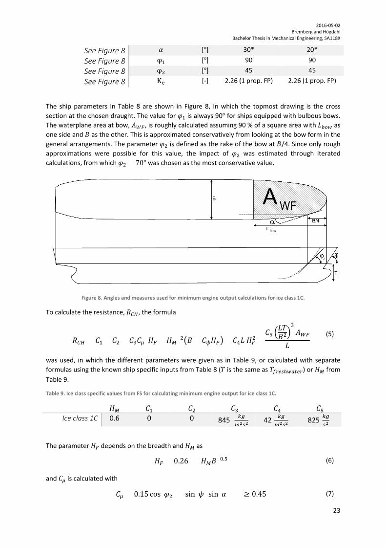
Table 6. Approximate plate thickness in forward, mid and aft region.
Entity Unit Crown Family Forward region [mm] 21.77 22.15
Mid region [mm] 15.24 15.44
Aft region [mm] 11.36 11.51
3.1.2. Structural framework Due to the nature of the input parameters and the prerequisite knowledge required for interpreting the steel drawings, this part lies outside the scope of this report. However, it is by no means a negligible concern. The main problem in determining sufficient scantlings is not that the procedure is inadequately described in FSICR (on the contrary the FSICR is very legible) but because the intended target group possess other resources (such as fully comprehensive drawings and information), not necessarily accessible by ship operators, commercial negotiators or investors. Regardless, by outlining the issue in part II, the latter parties are hopefully more proficient within the matter.
3.1.3. Strengthening of bow Both of the studied ships are equipped with a bulbous bow. This means that both of the ships need similar transitions between stem and bow, but also reinforcements such as stem plating on the outside and additional vertical stiffeners on the inside. The ice classes 1D and 1C have the same requirements in this case.
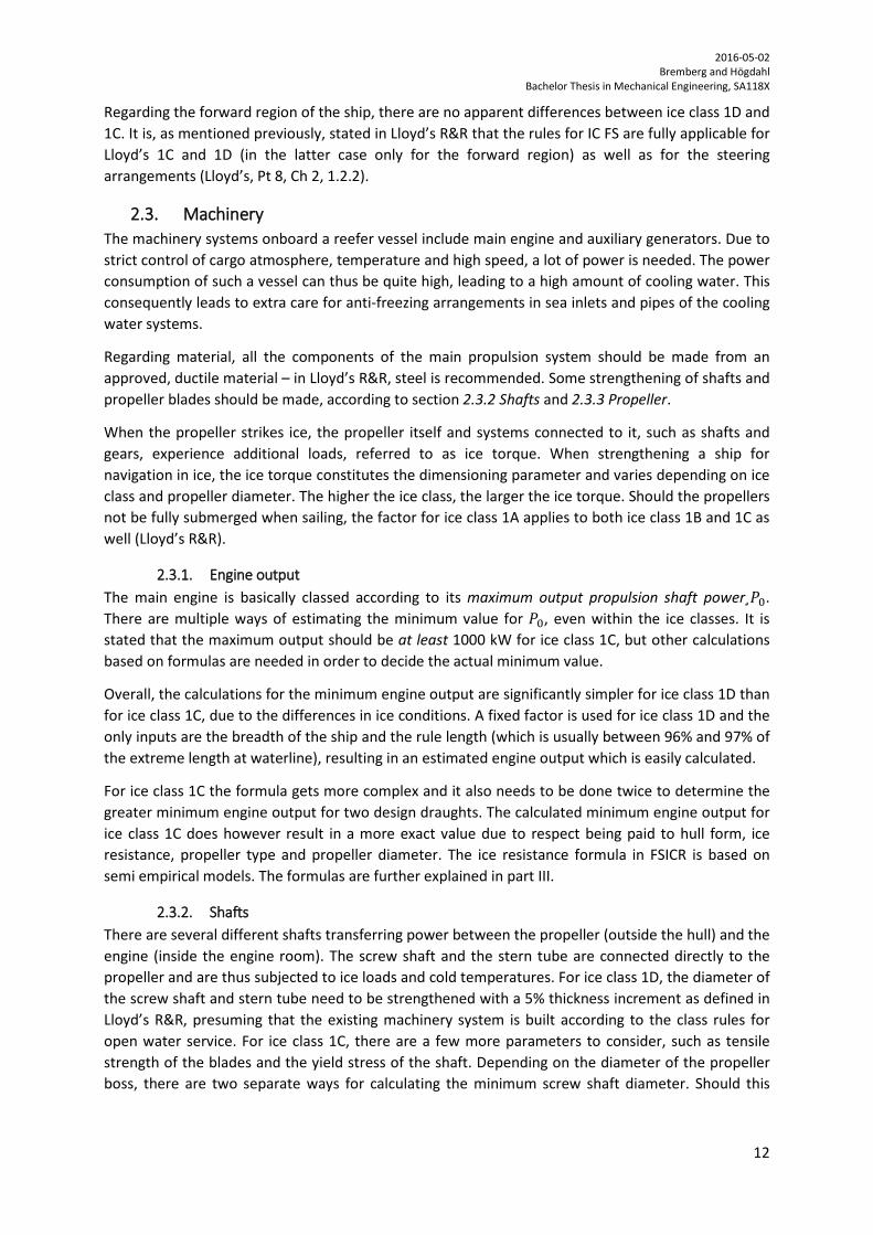
As evident in the general arrangement, the Family ship has a sharper bow transition compared to the Crown ship, as illustrated in Figure 7. A sharper angle of bulbous bow necessitates a bigger adjustment of this region in order to achieve a “smooth transition”.
Figure 7. Sketching highlighting the design differences of the bulbous bows, with Family ship DITLEV Reefer to the left and the Crown ship Crown GARNET to the right. The arrows indicate bow transition area.
3.1.4. Installed engine output As stated in 2.3 Machinery, some calculations are done to estimate the minimum engine output of the ship. The formula for ice class 1D is
𝑃𝑃0,1𝐷𝐷 = 0.72 ∙ 𝐵𝐵 ∙ 𝐵𝐵𝑓𝑓𝑟𝑟𝑏𝑏𝑤𝑤 (2)
with results in kW, providing that 𝐵𝐵𝑓𝑓𝑟𝑟𝑏𝑏𝑤𝑤 and 𝐵𝐵 are in meters. 𝐵𝐵 is the breadth while the rule length, 𝐵𝐵𝑓𝑓𝑟𝑟𝑏𝑏𝑤𝑤, is somewhere between 96 % and 97 % of the extreme length at waterline, 𝐵𝐵𝑏𝑏𝑝𝑝. To get an approximation of the biggest minimum output for ice class 1D, the rule length is therefore assumed to be

2016-05-02 Bremberg and Högdahl Bachelor Thesis in Mechanical Engineering, SA118X
22
𝐵𝐵𝑓𝑓𝑟𝑟𝑏𝑏𝑤𝑤 = 0.97 ∙ 𝐵𝐵𝑏𝑏𝑝𝑝, (3) with 𝐵𝐵𝑏𝑏𝑝𝑝 as given in the general arrangements. The breadth, 𝐵𝐵, is also read from the general arrangements. All the input values and results for the minimum engine output for ice class 1D are presented in Table 7.
Table 7. Input values and minimum engine output with respect to ice class 1D.
Entity Symbol Unit Crown Family Length (B.P) Lbp [m] 139.4 150.6
Breadth (MLD) B [m] 23 24
Rule length Lrule [m] 135.2 146.1
Required minimum engine output
P0ice class 1D [kW] 2039
2524
The Crown ship has a maximum continuous rating of 11920 kW and a normal output of 10132 kW (85 % of MCR). Both of the values for the installed output are roughly 5 times bigger than the required 2039 kW for ice class 1D, and a new engine is thus not needed.
The Family ship has a maximum continuous rating of 11250 kW, which is more than 4 times the minimum engine output for ice class 1D. Consequently, there is no need to install a stronger engine.
For ice class 1C, the calculations are a bit more complicated, as mentioned in 2.3 Machinery. The resistance from ice is taken into consideration and information about bow form, propeller diameter and draughts is needed. All the information needed is approximated conservatively from the general arrangements, except for the propeller diameter, which is clearly stated. This equation should be calculated twice, one for the draught at UIWL and the other for the draught at LIWL. Depending on the draught, the results will vary according to
𝑃𝑃0,≥1𝐶𝐶 =𝐾𝐾𝑤𝑤 �
𝐹𝐹𝐶𝐶𝐶𝐶1000�
3/2
𝐷𝐷𝑝𝑝
(4)
with results in kW. The variable 𝐾𝐾𝑤𝑤 is depending on number of propellers and the machinery and 𝐹𝐹𝐶𝐶𝐶𝐶 is the resistance estimated for sailing in channels with brash ice. 𝐷𝐷𝑝𝑝 is the propeller diameter. The resulting minimum engine output is the greater of the two calculations.
Table 8. Ship specific parameters for calculating minimum engine output for ice class 1C.
Entity Symbol Unit Crown Family Propeller diameter Dp [m] 6.2 5.4
Breadth (MLD) B [m] 23 24
Length (B.P) L [m] 139.4 150.6
Bow length2 Lbow [m] 60* 60*
Freshwater draught (summer)
Tfreshwater [m] 8.833 10.206
Forward waterplane area
AWF [m2] 1240* 1295*
2 The asterisk * indicates an approximate number.
2016-05-02 Bremberg and Högdahl Bachelor Thesis in Mechanical Engineering, SA118X
23
See Figure 8 𝛼𝛼 [°] 30* 20*
See Figure 8 φ1 [°] 90 90
See Figure 8 φ2 [°] 45 45
See Figure 8 Ke [-] 2.26 (1 prop. FP) 2.26 (1 prop. FP)
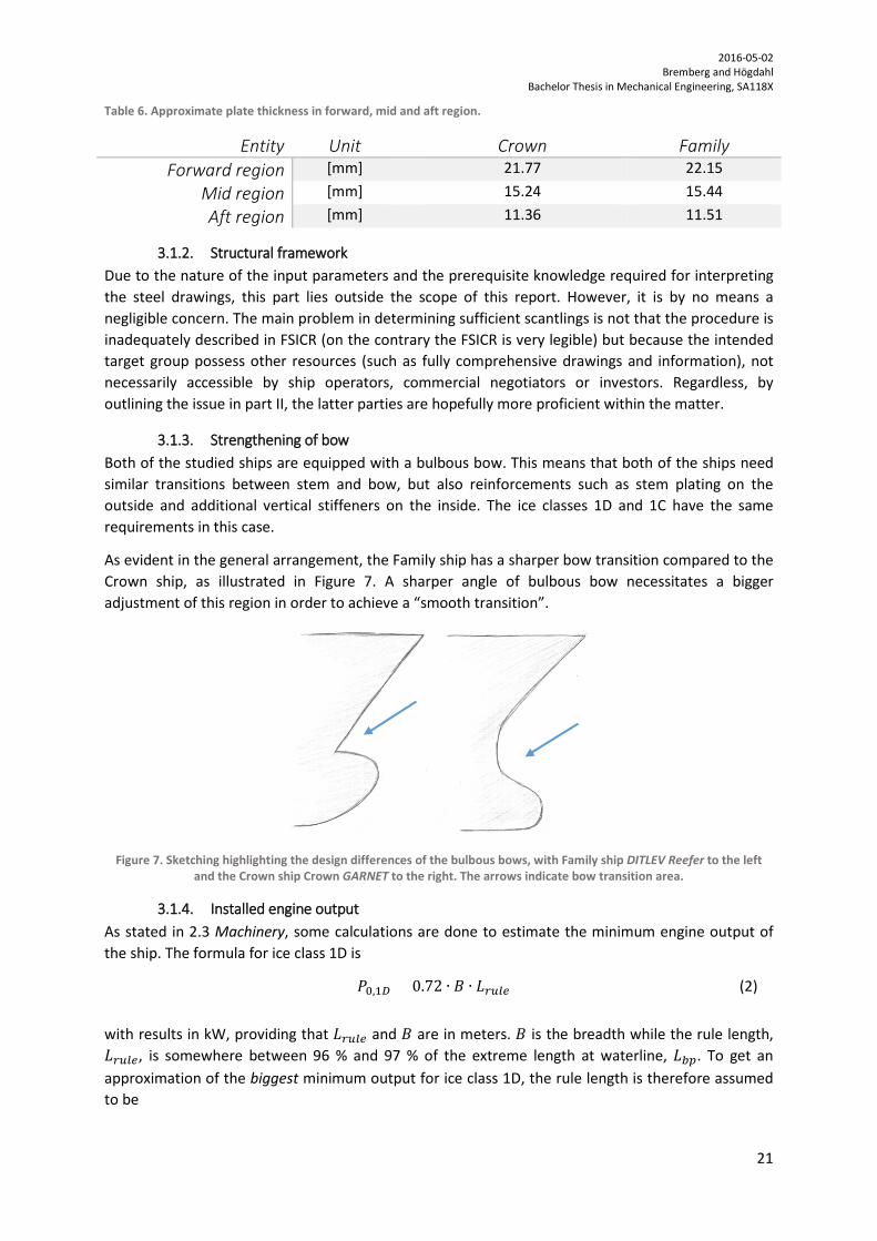
The ship parameters in Table 8 are shown in Figure 8, in which the topmost drawing is the cross section at the chosen draught. The value for 𝜑𝜑1 is always 90° for ships equipped with bulbous bows. The waterplane area at bow, 𝐴𝐴𝑊𝑊𝑊𝑊, is roughly calculated assuming 90 % of a square area with 𝐵𝐵𝑏𝑏𝑓𝑓𝑤𝑤 as one side and 𝐵𝐵 as the other. This is approximated conservatively from looking at the bow form in the general arrangements. The parameter 𝜑𝜑2 is defined as the rake of the bow at 𝐵𝐵/4. Since only rough approximations were possible for this value, the impact of 𝜑𝜑2 was estimated through iterated calculations, from which 𝜑𝜑2 = 70° was chosen as the most conservative value.
Figure 8. Angles and measures used for minimum engine output calculations for ice class 1C.
To calculate the resistance, 𝐹𝐹𝐶𝐶𝐶𝐶, the formula
𝐹𝐹𝐶𝐶𝐶𝐶 = 𝐶𝐶1 + 𝐶𝐶2 + 𝐶𝐶3𝐶𝐶𝜇𝜇(𝐻𝐻𝑊𝑊 + 𝐻𝐻𝑀𝑀)2�𝐵𝐵 + 𝐶𝐶𝜓𝜓𝐻𝐻𝑊𝑊� + 𝐶𝐶4𝐵𝐵 𝐻𝐻𝑊𝑊2 +𝐶𝐶5 �
𝐵𝐵𝐸𝐸𝐵𝐵2�
3𝐴𝐴𝑊𝑊𝑊𝑊
𝐵𝐵
(5)
was used, in which the different parameters were given as in Table 9, or calculated with separate formulas using the known ship specific inputs from Table 8 (𝐸𝐸 is the same as 𝐸𝐸𝑎𝑎𝑓𝑓𝑤𝑤𝑓𝑓ℎ𝑤𝑤𝑎𝑎𝑤𝑤𝑤𝑤𝑓𝑓) or 𝐻𝐻𝑀𝑀 from Table 9.
Table 9. Ice class specific values from FS for calculating minimum engine output for ice class 1C.
𝐻𝐻𝑀𝑀 𝐶𝐶1 𝐶𝐶2 𝐶𝐶3 𝐶𝐶4 𝐶𝐶5 Ice class 1C 0.6 0 0 845 [ 𝑘𝑘𝑐𝑐
𝑚𝑚2𝑓𝑓2] 42[ 𝑘𝑘𝑐𝑐
𝑚𝑚2𝑓𝑓2] 825[𝑘𝑘𝑐𝑐
𝑓𝑓2]
The parameter 𝐻𝐻𝑊𝑊 depends on the breadth and 𝐻𝐻𝑀𝑀 as
𝐻𝐻𝑊𝑊 = 0.26 + (𝐻𝐻𝑀𝑀𝐵𝐵)0.5
(6)
and 𝐶𝐶𝜇𝜇 is calculated with
𝐶𝐶𝜇𝜇 = 0.15 cos(𝜑𝜑2) + sin(𝜓𝜓) sin(𝛼𝛼) ≥ 0.45 (7)

2016-05-02 Bremberg and Högdahl Bachelor Thesis in Mechanical Engineering, SA118X
24
for which it should be noted that the lowest value is 0.45 as stated above. The angle 𝜓𝜓 is calculated from the different rake angles of the ship that are displayed in Table 8 as
ψ = arctan(
tan(φ2)sin(α) ).
(8)
If 𝜓𝜓 ≤ 45°, then
𝐶𝐶𝜓𝜓 = 0
and if 𝜓𝜓 is higher than that, 𝐶𝐶𝜓𝜓 is calculated using
𝐶𝐶𝜓𝜓 = 0.047𝜓𝜓 − 2.115. (9)
With all the parameters known in equation (5), the resistance was calculated and the minimum engine output was derived from equation (4). The calculated resistance and minimum engine output for the ships are displayed in Table 10.
Table 10. Calculated resistance and minimum engine output for ice class 1C.
Entity Symbol Unit Crown Family Resistance RCH [kN] 445 467
Required minimum engine output P0ice class 1C [kW] 3400 4221
Consequently, both the Crown and the Family ship already fulfill the requirements regarding main engine output for both ice class 1D and 1C.
As mentioned before, the FSICR stipulates a minimum engine output that must be met, since many scantling calculations in the procedure depend on this number. However, if there is a redundancy of engine output the ship owner may choose to establish a lower “maximum” engine output specifically for sailing in ice (than what the installed engine allows). A restriction of the allowed output can be useful in order to lessen the design ice pressure and propeller load, hence reducing some of the measures necessary to achieve sought ice notation. The ship owner might then avoid a change of propeller or strengthening of screw shafts, which otherwise could be a costly change to suffer. Also, since the ice pressure directly affects the thickness of shell plating and the section modulus of structural members, additional savings can be achieved by reducing the sailing speed.
3.1.5. Propeller and shaft As stated in 2.3.2 Shafts, an increase of diameter thickness of screw and tube shafts is a necessary reinforcement when strengthening towards 1D and 1C. A 5 % increment should be applied if the ship is built for open water service, in accordance with Lloyd’s R&R. Assuming the ships are built for the exact standard for non-ice classed vessels; this would require a change of screw and tube shafts. It is known that the Family ship is built according to Lloyd’s and this is thus most applicable to that ship, whereas the Crown ship might have different standards to begin with.
The propeller reinforcement, and also the shaft strengthening, depend on the ice torque, 𝐷𝐷𝑤𝑤, as mentioned in 2.3 Machinery, which can be calculated using
𝐷𝐷𝑤𝑤 = 𝑚𝑚1𝐶𝐶 ∙ 𝐷𝐷𝑝𝑝2
in tonmeters and in which 𝑚𝑚1𝐶𝐶=1.22 for ice class 1C and 𝐷𝐷𝑝𝑝 is the propeller diameter, which is available in Table 8. For the Crown ship the ice torque is 46.9 tonmeters and for the Family ship it is
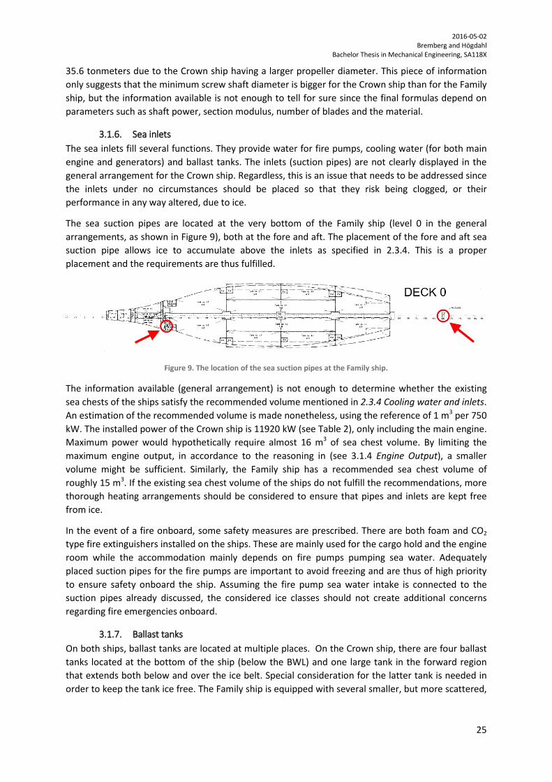
2016-05-02 Bremberg and Högdahl Bachelor Thesis in Mechanical Engineering, SA118X
25
35.6 tonmeters due to the Crown ship having a larger propeller diameter. This piece of information only suggests that the minimum screw shaft diameter is bigger for the Crown ship than for the Family ship, but the information available is not enough to tell for sure since the final formulas depend on parameters such as shaft power, section modulus, number of blades and the material.
3.1.6. Sea inlets The sea inlets fill several functions. They provide water for fire pumps, cooling water (for both main engine and generators) and ballast tanks. The inlets (suction pipes) are not clearly displayed in the general arrangement for the Crown ship. Regardless, this is an issue that needs to be addressed since the inlets under no circumstances should be placed so that they risk being clogged, or their performance in any way altered, due to ice.
The sea suction pipes are located at the very bottom of the Family ship (level 0 in the general arrangements, as shown in Figure 9), both at the fore and aft. The placement of the fore and aft sea suction pipe allows ice to accumulate above the inlets as specified in 2.3.4. This is a proper placement and the requirements are thus fulfilled.
Figure 9. The location of the sea suction pipes at the Family ship.
The information available (general arrangement) is not enough to determine whether the existing sea chests of the ships satisfy the recommended volume mentioned in 2.3.4 Cooling water and inlets. An estimation of the recommended volume is made nonetheless, using the reference of 1 m3 per 750 kW. The installed power of the Crown ship is 11920 kW (see Table 2), only including the main engine. Maximum power would hypothetically require almost 16 m3 of sea chest volume. By limiting the maximum engine output, in accordance to the reasoning in (see 3.1.4 Engine Output), a smaller volume might be sufficient. Similarly, the Family ship has a recommended sea chest volume of roughly 15 m3. If the existing sea chest volume of the ships do not fulfill the recommendations, more thorough heating arrangements should be considered to ensure that pipes and inlets are kept free from ice.
In the event of a fire onboard, some safety measures are prescribed. There are both foam and CO2 type fire extinguishers installed on the ships. These are mainly used for the cargo hold and the engine room while the accommodation mainly depends on fire pumps pumping sea water. Adequately placed suction pipes for the fire pumps are important to avoid freezing and are thus of high priority to ensure safety onboard the ship. Assuming the fire pump sea water intake is connected to the suction pipes already discussed, the considered ice classes should not create additional concerns regarding fire emergencies onboard.
3.1.7. Ballast tanks On both ships, ballast tanks are located at multiple places. On the Crown ship, there are four ballast tanks located at the bottom of the ship (below the BWL) and one large tank in the forward region that extends both below and over the ice belt. Special consideration for the latter tank is needed in order to keep the tank ice free. The Family ship is equipped with several smaller, but more scattered,

2016-05-02 Bremberg and Högdahl Bachelor Thesis in Mechanical Engineering, SA118X
26
tanks. The ballast water tanks located at the 3rd and 4th deck of the Family ship should be equipped with sufficient anti freezing arrangements. The other ballast water tanks are located below the BWL.
3.2. Summary The required alterations necessary to strengthen the Family and Crown ships are ultimately quite similar, mainly because the ships are of similar size and type. Of course, this may only be true in the more general case, since every detail of ice class strengthening has not been approached. Estimating exact details regarding propellers and the framing has proven difficult in relation to the means available (general arrangements for both ships and steel drawing for the Family ship exclusively).
Some parts do not need to be modified in order to reach an ice class, one example is the installed main engine shown in Table 11. Other parts require more comprehensive measures, such as the shell plating necessary to endure the additional ice pressure.
Different bulbous bow designs result in a more tedious ice strengthening of the Family ship in the forward region compared to the Crown ship.
Table 11. Results for minimum required engine output in comparison to currently installed output.
Entity Ice class Crown Family Minimum Engine Output 1D 2039kW 2524kW
1C 3400kW 4220kW Installed Engine Output 11920kW 11250kW

2016-05-02 Bremberg and Högdahl Bachelor Thesis in Mechanical Engineering, SA118X
27
PART IV In the previous two parts, this report has strived to compile and, in theory, implement some of the measures necessary in order to achieve sought notation. Through the report, the issue of ice class strengthening has been advanced to a position where the company behind the inquiry has acquired some means to perceive, and make, strategic decisions based upon their own commercial prerequisites and business logic. The process of ice strengthening may be regarded as iterative where separate considerations are advanced through refinement. Next step in said process, or the third iteration, is to establish and understand what practical factors are governing the strengthening of each ship and make some cost predictions for each measure. Earlier, these necessary measures have been segmented to different parts such as machinery, waterline strengthening, shafts, etc. Part IV will focus on waterline strengthening, and more specifically, the shell plating of the ice belt.
4. The third iteration In this iteration, two different approximations of steel amount and cost is presented. Ultimately, the aim is to comment upon each notation’s financial viability, in relation to the ice belt.
4.1. Strengthening the hull There are two possible ways of thickening the shell plating in order to withstand higher pressures due to external ice loads. Firstly, the existing plate within the ice belt may be removed and then replaced with plating of the correct thickness (replacement method, RM). Alternatively, additional plates (so called doublers) are welded onto the existing plating (doubler method, DM). Whilst both methods can be used, most classification societies do not accept the doubler method, which may be due to the fact that the aggregate of several plates does not compare to the same amount of material in one piece. In other words, the mechanical properties of a solid plate are better than the properties of its areal twin, made of stacked plates. When choosing between the two, this results in solid (RM) plates being thinner than the doubler plates, covering the same section of the ice belt. Regardless, doublers are most often associated with temporary repair of the hull.
Two societies that do allow doublers is Det Norske Veritas (DNV) and Bureau Veritas (BV). According to DNV, the breadth of doublers should not exceed 250 mm in the foreship and 325 mm elsewhere. Adjacent doublers are to be connected with full penetration welding and slot welds shall not be used in the foreship (Det Norske Veritas AS, 2013).
In cases where both methods are applicable, or where the doubler method appears practical, the existing plate thickness needs to be established in order to enable a comparison of each method’s merits. This can be done through ultrasonic thickness measurements of the hull, which is a local, accurate and also non-destructive method. Of course, the owner or operator should have an idea about the initial thickness through both class regulations and knowledge concerning their administration of the ship. It would however be negligent to assume full insight and hence

2016-05-02 Bremberg and Högdahl Bachelor Thesis in Mechanical Engineering, SA118X
28
compromise the safety of the ship, whereas the ultrasonic thickness measurements might make a good complement.
To exemplify the difference between the RM and DM method, one might consider the Family ship. Through correspondence with Markos Paspalas (working for the reefer ship owner Chartworld) who is currently investigating ice belt strengthening to ice class 1D on Family class ships based on BV’s calculation procedures, following values have been conveyed. Apparently, the Family ship’s existing plate thickness is 14 mm between the 178th frame and the forward end of the ship, and 11 mm from the 96th to 178th frame, see Figure 10. The BV calculation results are tabled in Table 12. It should be noted that the thickness calculation regarding the foremost frames (based on Lloyd’s procedure) have been refined from what is presented in Part III. In other words, the denser frame spacing (0.615 m instead of 0.82 m) in front of the 178th frame has been considered.
Figure 10. Frames in forward region; frames: 96-178 and 178- forward end (FE).
Table 12. Comparison between BV's replacement and doubler method (RM and DM) for ice belt thickness in relation to Lloyd's Register’s replacement thickness.
Frames Unit Lloyd’s, RM BV, RM BV, DM 178th to
forward end [mm] 19.1 19 14+14
96th to 178th [mm] 22.2 23 11+20
As already mentioned, the mechanical properties for a solid plate are not the same as for a doubler plate, which is evident in Table 12. The results may however act as verification of the values achieved in Part III of this report. Firstly, because the results are closely resembling each other and secondly, because they were independently derived from different societies’ classification procedures.
4.2. Ice belt area and volume When designing and building a ship there are several professionals working both together and in succession. Generally, a naval architect designs hull shape, ship dimensions and the general arrangement of a ship. The “hull planner” decides block breakdown preceding the construction, then, the structural engineer defines the shell plates. Each part makes decisions that have consequences for the next. When progressing a ship construction project, producibility concerns and technical considerations do not always align. As in other businesses, problems of such nature can be offset by good transboundary knowledge which in turn may reduce realisation cost. One such problem is that it is mathematically impossible to model exact double curvature plating and consequently, the ideal surface shape will never be achieved (Lamb, 1994). Further, it would be equally testing to construct such a surface and attach it to the frame.

2016-05-02 Bremberg and Högdahl Bachelor Thesis in Mechanical Engineering, SA118X
29
In order to compare the amount of shell plating necessary for each ship and to ultimately comment upon the cost of strengthening the ice belt, the ice belt area is determined through two different methods. The reason being that a comparison between these methods may indicate the approximation’s sensitivity, and further, its legitimacy. There are several problems governing the accuracy in such an analysis. As stated above, it is a complex endeavor to mathematically model surfaces with double curvature, and whilst restricted to general arrangements, this proves even harder. In order to bridge the lack of tools available, this analysis will rely partly on a semi empirical formula for approximating the wetted surface area at different draughts (mainly used when initially approximating resistance during sailing) and partly on basic geometry.
4.2.1. Method 1 Firstly, the ice belt area is modelled as a planar projection (in two dimensions), thereby neglecting the curvature of the hull. The calculated extent of the ice belt, as shown in Figure 5 and Figure 6 (and tabled in Table 4), provide the input for this method. The projected geometries are presented in Figure 11.
Based on Figure 11, the length of the forward region is roughly 53 % of the Crown ship and 46% of the Family ship. The ice belt length is taken as the length between perpendiculars and the blue area shows the estimated expanse of the forward region.
Figure 11. Projected ice belt area for the Crown ship (upper) and the Family ship (lower), with notations in meters. Blue indicates the forward region. The upper ice belt border is taken at the UIWL+0.4 m.
Through basic geometry (square and triangle area calculation), the total ice belt area is determined as displayed in Table 13. The length of the mid and aft region is estimated in the same way as the forward region.
Table 13. Approximated shell plating area of one side, without consideration to hull curvature.
Region Unit Crown Family Forward [m2] 450 496
Mid [m2] 159 271
Aft [m2] 127 219
Total [m2] 736 986
The total shell plating volume inside the ice belt is calculated through multiplying the ice belt area with the shell plating thickness for each region respectively. The results are displayed in Table 14. Please note that these values are solely for comparison and house a substantial error due to extensive approximations.

2016-05-02 Bremberg and Högdahl Bachelor Thesis in Mechanical Engineering, SA118X
30
Table 14. Estimated shell plating volume of one side between each ship and ice class.
Shell plating Volume Ice class Unit Crown Family Forward region 1D [m3] 9.8 11
All regions 1C [m3] 14 18
4.2.2. Method 2 In order to include hull curvature in the area estimation, a semi-empirical formula for wetted surface area was used. The formula for wetted surface area (Garme, 2012),
𝐴𝐴𝑤𝑤𝑤𝑤𝑤𝑤 = 1.025 ∙ 𝐵𝐵𝑏𝑏𝑝𝑝(𝐶𝐶𝐵𝐵 ∙ 𝐵𝐵 + 1.7 ∙ 𝐸𝐸), (10) was used in which 𝐵𝐵𝑏𝑏𝑝𝑝 is the length between perpendiculars, 𝐶𝐶𝐵𝐵 is the block coefficient (0.57 for the Crown ship), B is the breadth and T is the regarded draught. To begin with, some assumptions relating to the formula were made. For example, the data (on which the formula is built) is assumed to have been gathered through testing a variety of ship types, each at several draughts, hence including an average curvature of a ship at any draught. It is also assumed (in the calculations) that 𝐶𝐶𝐵𝐵 is approximately the same for both ships. To clarify the meaning of “wetted surface area”, it should be understood that the wetted surface is the same surface as the outer area of the hull structure below the waterline.
To isolate, or perhaps more accurately, frame, the area of the ice belt, different draughts were used as well as geometrical assumptions. At the ice belt’s upper limit, the draught is regarded as UIWL + 0.4 m. The bottom line is angled, as shown in Figure 12, and the ice belt is thus regarded as two parts: a triangle and a rectangle, similar to the geometrical calculations in method 1.
Figure 12. The ice belt area (shadowed) divided in two parts, one square and one triangle.
At first, the complete wetted area, was calculated at UIWL+0.4 m. The light grey area in Figure 12 was then calculated as the complete area subtracted by the area underneath the light grey area (at the aft draught LIWL-0.5 m). The calculations for the triangle (dark grey in Figure 12) were performed in the same way (that is, calculated as a rectangle), and was thereafter divided by two. It should be noted that equation (10) gives the ice belt area of both the port and starboard side, and hence have been divided by two preceding the comparison in Table 16.
The input values for method 2 are displayed in Table 15.

2016-05-02 Bremberg and Högdahl Bachelor Thesis in Mechanical Engineering, SA118X
31
Table 15. Input values for ice belt area calculations.
Entity Symbol Unit Crown Family Block coefficient CB - 0.57 0.57*
Breadth (MLD) B [m] 23 24
Length (B.P) Lbp [m] 139 150.6
Freshwater draught (summer) TUIWL [m] 8.833 10.2
Forward LIWL draught Tforward,LIWL [m] 2.45 3.35
Aft LIWL draught Taft,LIWL [m] 5.7 4.9
Using equation (10) and the general geometry shown in Figure 12, the total ice belt area for one side of the ship is calculated to 687 m2 for the Crown ship and 915 m2 for the Family ship. This is the total area that needs to be covered for ice class 1C.
To estimate the strengthened ice belt area for ice class 1D, that is, the area in the forward region, the same forward area percentage as given in method 1 is used. From Table 13, it is apparent that the forward area in method 1 makes up 61% of the ice belt region for the Crown ship and 50% for the Family ship. By using this value, it is ensured that both methods are comparable. However, any error in the approximation of forward region extension, will be present in the result of method 2 as well.
The ice belt area in the forward, mid and aft region of the ice belt is estimated by the percentage of areas in Table 13. The results are displayed in Table 16.
Table 16. Ice belt area of one side divided by regions (result from method 1 is written in the parenthesis for comparison).
Region Unit Crown Family Forward [m2] 419 (450) 458 (496)
Mid [m2] 148 (159) 251 (271)
Aft [m2] 120 (127) 206 (219)
Total [m2] 687 (736) 915 (986)
Analogous to method 1, the volume is calculated using the plate thickness displayed in Table 6. The volumes are displayed in Table 17, with the numbers from method 1 in parentheses and mean volume in brackets.
Table 17. Shell plating volume of one side with results from method 2 (result from method 1 is written in the parenthesis for comparison).
Shell plating Volume
Ice class Unit Crown Family Mean volume [Crown, Family]
Forward region 1D [m3] 9.1 (9.8) 10 (11) [9.45, 10.5]
All regions 1C [m3] 13 (14) 16 (18) [13.5, 17]
Conclusively, the results from both methods are similar. This indicates that the numbers are credible and that they may be used for a perspicuous analysis.

2016-05-02 Bremberg and Högdahl Bachelor Thesis in Mechanical Engineering, SA118X
32
4.3. Weight and cost of ice belt The weight of the ice belt depends on the choice of steel. In the FSICR it is suggested to use S235, which is a normal-strength structural steel. Structural steel has a density ranging between 7.8 ton and 7.9 ton per cubic meter (Granta Design, 2015). The volume is taken as the mean value of the results in the previous section, found in Table 17. The density is also taken as the mean density (7.85 ton per cubic meter).
When estimating material cost, it is important to note that the market price of steel fluctuates daily. In the year of 2007, the Swedish steel price was roughly 40 SEK per kg (Mohlin, 2016). Considering the inflation rate preceding 2016 (from the year 2007), provided by the administrative agency Statistics Sweden, the corresponding present day value amounts to 43.47 SEK per kg (Statistiska centralbyrån, 2016). The final weight and suggested material (steel) price of the ice belt are displayed in Table 18 for each ship and ice class.
Table 18. Weight and material cost for the entire ice belt.
Ice class Unit Crown Family 1D Weight [kg] 146 640 163 800
Material cost [SEK] 6 374 440 7 120 386
1C Weight [kg] 210 600 265 200
Material cost [SEK] 9 154 782 11 528 244
As stated above, the results tabled in Table 18. Weight and material cost for the entire ice belt. Table 18 represent the predicted steel cost for each ship and ice class. Of course, this cost is only part of the final expenditure that should be expected. Additionally, there are also costs due to off-hire time (loss of income), docking, work, and overhead, to name the primary ones. Secondary costs, specifically for ice belt strengthening, could be removal and refitting of insulation, blast painting and accessibility of the target location (it is far more difficult to conduct welding operations in the fore peak than in the cargo space, why such operations may be charged with an additional percentage). As a rule of thumb, one might expect that half the expenses invested in rebuilding a ship will be material costs, whereas the other half is a combination of the costs mentioned above.
In correspondence with the aforementioned constructor, working on the Family ship, an estimate of €6-9 per kg steel and associated work were suggested. The total cost of steel and work (TCSW) for strengthening the ice belt was then considered. These results are presented in Table 19 and was calculated in relation to the required steel mass specified in Table 18. A conversion rate of 9.19 SEK/€ (date: 2016-04-29) were used.
Table 19. Total cost of steel and work (TCSW) depending on two aggregate cost (material and work cost) alternatives.
Ice class Cost alternative Unit Crown Family 1D TCSW for 6€/kg [SEK] 8 085 730 9 031 932
TCSW for 9€/kg [SEK] 12 128 595 13 547 898
1C TCSW for 6€/kg [SEK] 11 612 484 14 623 128
TCSW for 9€/kg [SEK] 17 418 726 21 934 692
Based on the results presented in Table 18 and Table 19, the material and work cost relation are displayed in Table 20.

2016-05-02 Bremberg and Högdahl Bachelor Thesis in Mechanical Engineering, SA118X
33
Table 20. Material cost percentage of aggregate price (tabled in Table 19).
Entity Cost range Unit Crown Family Material cost in
relation to TCSW regardless of ice class
TCSW for 6-9€/kg [%] 78.8 and 52.6 78.8 and 52.6
As shown in Table 20, the higher TCSW generate a cost reminiscent of that expected from the aforementioned rule of thumb of 50 % material cost and 50 % work cost. The diverging relation for the lower TCSW could probably be ascribed to the, generally higher (compared to, say, Turkish), cost of Swedish steel. As a final verification it should be mentioned that the constructor had concluded a total cost of 1 million euro (9.2 million SEK), which is close to the approximation presented in Table 19, regarding the Family ship and 1D notation. Conclusively, the results regarding the other combinations should be equally valid, due to the nature of the methods. In other words, a comparison between ice class notion 1D and 1C for two existing reefer vessels have been achieved.
4.4. Summary In summation of Part IV, it should first be stated that the results only represent an initial cost estimation. Such an estimate can be used as a baseline when evaluating quotes and potential shipyards, but also as a tool facilitating both internal and external communication. The results constitute of a price-range for both ships and notations around which the ultimate cost of steel and work will likely befall. Through correspondence with a ship owner working on the Family ship with ties to Cool Carriers, a suitable verification of the 1D ice belt cost was enabled and performed.

2016-05-02 Bremberg and Högdahl Bachelor Thesis in Mechanical Engineering, SA118X
34
Discussion To peremptorily answer whether a certain ice class is more appropriate than another, holistic information concerning trade routes, expected life before scrapping and other ship specifications, must first be acquired in its entirety. Such a process is investigatory and consists of several design stages, in which this report is intended to facilitate the opening stage. Hence, due to the uncertainties of this design stage, this report can only provide estimative examples which indicate the consequences of ice class strengthening.
To exemplify the difference of ice classes 1D and 1C, one might consider the installed engine output. If the installed engine output is less than the defined minimum requirement, specified in 2.3 Machinery, the difference in cost between the classes will increase significantly. For instance, in the case of the installed engine output meeting the requirements for 1D, but not for 1C, the economic incentives for choosing the latter weakens. The reason for this is that many auxiliary systems are dependent on the machinery. In this scenario, 1D would infer some strengthening measures while the alternative, 1C, would demand a comparatively severe alteration of the existing systems.
Nonetheless, the engine output plays an important role regardless if the minimum requirements are met or not since several parameters in the ice strengthening procedure are dependent on this number. Two examples are the design ice pressure (which is correlated to all structural strengthening) and sea chest capacity for cooling water. Ultimately, it is concluded in Part III that the installed engine output, on both ships, is enough to meet the requirements for both ice classes 1D and 1C. This could, with other words, be taken as an incentive to strengthen the ships in accordance to 1C, since some of the benefits for doing so come “free of charge”.
If this comparison is expanded to include the shell plating as well, it becomes apparent that the requirements for 1C result in significantly more added mass than for 1D. This will in turn cause a higher LIWL due to the extra mass (not only from the shell plating but also from the associated structural strengthening) and consequently lower the ship’s cargo capacity. The negative effect on cargo capacity thwart the case for 1C and argue the case of 1D, if considering the possible revenues from singular trips.
Further, it is also possible that the ship, from a performance perspective, could benefit from the extra weight due to fuller propeller submergence in ballasted sailing, advocating the higher ice class. Of course, increased propeller submergence and fuel consumption lies on opposite sides of the scale, demanding additional investigation.
Previously, the prerequisites for each ice class have been investigated. However, two questions still remain; is there a significant difference in how each ship responds to ice strengthening to the same class from a cost perspective, and if so, which ship should preferably be designated which notation? Firstly, the answer to the initial question is yes. Mainly because the ships are of different sizes and thus need different amount of, say, material (in order to achieve the same ice going capabilities). To answer the latter question, one might consider the additional cost, effort or stakes such an operation might infer.
As illustrated in the examples above, a multitude of different aspects, comprising of trade-offs and potential gains, governs the ultimate choice whether to choose a lighter or more comprehensive ice class. The lighter class might be a sensible target in order to meet the need of a quick return on investment whilst the more rigorous choice could heighten the annual utilisation ratio of the ship, thus increasing yearly revenues. Regardless, some of the more noteworthy aspects influencing the choice are listed below.

2016-05-02 Bremberg and Högdahl Bachelor Thesis in Mechanical Engineering, SA118X
35
Factors that need to be considered when ice strengthening:
• Return on investment (life span of ship and cost). • Which classification the ship originally has and what the target classification is. • Which trades are important (ballast and trim condition affect waterline strengthening). • The ship’s parameters need to be reevaluated after the ice strengthening (further work). • The ice strengthening’s impact on the ship’s scrapping value (which is related to the
lightweight of the ship).
The issue of target group and comprehensiveness When attempting to follow the FSICR calculation procedure for ice strengthening of the structural framing, it quickly becomes evident that prior knowledge about ship construction is required. One pressing issue is to adequately understand and make acceptable assumptions regarding span lengths and discerning type of framing. In short, this does not facilitate a dialogue between different parties investigating the strengthening of a ship due to the extensive amount of prior knowledge necessary to follow the procedure. Consequently, a potential investor should be aware that some additional resources might be necessary to bridge this part.
Possible benefits of acquiring this knowledge are, firstly, to understand the extent of the required modifications and secondly, to gain some overview of cost before advancing the issue further. To some extent, it is possible for laymen (or someone trying to assess the need of a specialist) to calculate, say, the required thickness of shell plating and to compare this to the class rules on which the ship was built to gain some perspective on the cost of this singular measure. Of course, without access to steel drawings and sufficient knowledge of nomenclature, hull construction and force propagation, it will prove difficult to contain and exploit results.
Future work Future work should comprise of a more thorough investigation of ice class strengthening to each notation, including areas such as the structural framework and propeller dimensions, which in the early stage of this report have been omitted. Also, as each part is refined, a more detailed comparison between the notations becomes possible.
Other interesting topics to approach in future studies could be a comparative study between reefer vessels and other cargo vessels (to investigate differences caused by ship type) or if the rules regarding strengthening to ice class differ from the rules of new ship being built according to ice class from the beginning.
It would also be interesting to compare an ice strengthening’s effect on the ships expected life. To what extent do the measures overlap when reinvesting for increased life expectancy compared to an ice strengthening? Which costs of maintenance do not need to be observed? What cost remains? Does this create incentives for actually investing in maintenance and how does this affect the choice of class? Would ice class reduce the total maintenance cost on a short or long term basis?

2016-05-02 Bremberg and Högdahl Bachelor Thesis in Mechanical Engineering, SA118X
36
Conclusions There are multiple factors, such as cost, safety and harbor regulations, affecting the decision whether to strengthen the ship to ice class 1C or 1D.
As concluded in the summary of part II, there are several necessary measures that are the same, but also several measures that differ, between the notations 1D and 1C. Naturally, when comparatively considering two ice classes, it is the differences that matter. These consist of
• Regions considered for waterline strengthening • Stern and bow strengthening • Structural strengthening • Machinery • Minimum propeller blade edge and tip thickness • Shafts • Sea Chests • Bilge keels
For the Crown and Family ships, the differences are highlighted in the summary of part III. It is apparent that the differences in engine output are negligible. Further, Part IV provide a detailed analysis of ice belt strengthening and an initial cost prediction. It is concluded, through an independent verification, that the comparison is applicatory in an early design stage. Depending on steel price and sought ice notation the cost range from 8.1 to 17.4 million SEK for the Crown ship and 9.0 to 21.9 million SEK for the Family ship. For a more detailed account, see Table 19 in section 4.3 Weight and cost of ice belt.
A definite solution for which one of the ice classes is better, does not exist at this stage. Instead, guidelines for when a strengthening would be profitable are extrapolated from information about the differences of ice class strengthening and the intended use of the ships. If, for example, the Crown class is intended for shipping perishable goods to St. Petersburg all year round, the incentives for converting the ship to ice class 1C are strong, due to a higher reliability in ETA. The effects of added weight and higher expenses could however advocate ice class 1D. Similarly, should the Family class only sail sporadically to St. Petersburg, it could be more financially sensible to convert the ship to ice class 1D.
2016-05-02 Bremberg and Högdahl Bachelor Thesis in Mechanical Engineering, SA118X
37
Bibliography Berggren, A. & Lindh, E., 2014. ICE LOADS AND RESISTANCES ON A SMALL COMMUTER VESSEL -A comparative study of rule based design and analytical ice loads and resistances, Stockholm: KTH Centre of Naval Architecture.
Canadian Coast Guard, 2013. ccg-gcc.gc. [Online] Available at: http://www.ccg-gcc.gc.ca/e0010988 [Accessed 04 03 2016].
Carlton, J., 2012. Propeller Tolerances and Inspection. III red. Great Britain: Elsevier Ltd.
Det Norske Veritas AS, 2013. Conversion of Ships, Norway: Det Norske Veritas AS.
Drewry Maritime Research , 2013. Reefer Shipping Market Review and Forecast (annual report), London: Nigel Gardiner.
Ericson, M. & Lake, H., 2014. LENGTHENING OF A SPECIALIZED REEFER SHIP -Is it Economically Viable?, Stockholm: KTH Centre for Naval Architecture.
Eyres, D., 2007. Fore End Structure. i: E. Ltd, red. Ship Construction. 1:a red. Plymouth: Elsevier Ltd, pp. 228-229.
Garme, K., 2012. Ship Resistance and Powering, SD2710 INITIAL SHIP DESIGN, Course notes, Stockholm: KTH.
Granta Design, 2015. CES Edupack. Cambridge: Granta Design.
Inchcape Shipping Services (ISS), 2016. iss-shipping. [Online] Available at: http://www.iss-shipping.com/cargo/cargo_library_glossarys.asp [Accessed 23 02 2016].
Kurs-PM, 2016. Kurs-PM (Kandidatexamenskurser, Naval Architecture), Stockholm: Marina System, KTH.
Lloyd's Register, 2016. Lloyd's Rules and Regulations for the Classification of Ships, London: Lloyd's Register Group.
Lloyd's Register, 2016. lr. [Online] Available at: http://www.lr.org/en/ [Accessed 22 02 2016].
Lundh, H., 2013. Grundläggande hållfasthetslära. 3:e red. Stockholm: Hans Lundh.
Mohlin, R., 2016. Cool Carriers [Interview] (23 02 2016).
Mohlin, R., 2016. Cool Carriers [Interview] (27 04 2016).
Mohlin, R., 2016. Cool Carriers [Interview] (22 02 2016).
Molland, A., 2008. Maritime engineering reference book. 1:a red. Oxford: Elsevier.
Nationalencyklopedin, u.d. Nationalencyklopedin. [Online] Available at: http://www.ne.se/uppslagsverk/encyklopedi/l%C3%A5ng/%C3%B6stersj%C3%B6n [Använd 8 Februari 2016].
Sjöfartsverket, 1986. Sjöfartsverkets författningssamling, Norrköping: Sjöfartsverket.

2016-05-02 Bremberg and Högdahl Bachelor Thesis in Mechanical Engineering, SA118X
38
Sjöfartsverket, 2012. “FINNISH-SWEDISH ICE CLASS RULES”: THE STRUCTURAL DESIGN AND ENGINE OUTPUT REQUIRED OF SHIPS, Norrköping: Sjöfartsverket.
SMHI, 2014. SMHI.se. [Online] Available at: http://www.smhi.se/en/services/professional-services/shipping/baltic-sea-ice-code-1.8965 [Använd 8 Februari 2016].
Statistiska centralbyrån, 2016. sverigeisiffror.scb. [Online] Available at: http://www.sverigeisiffror.scb.se/hitta-statistik/sverige-i-siffror/prisomraknaren/ [Använd 02 05 2016].
Svensk Sjöfarts Tidning, 2013. Sjöfartens bok. 1 red. Göteborg: Svensk Sjöfarts Tidnings Förlag AB .
Trafiksäkerhetsverket, 2010. Sjösäkerhetsföreskrift: Isklassföreskrifter och tillämpning av dem, Helsingfors: Trafiksäkerhetsverket.
Transport Safety Agency , 2010. FINNISH ICE CLASSES EQUIVALENT TO CLASS NOTATIONS, Helsingfors: Trafiksäkerhetsverket.
Transportstyrelsen, 2011. Transportstyrelsens föreskrifter och allmänna råd om finsk-svensk isklass, Helsingfors: Transportstyrelsens författningssamling.
Wikipedia, 2015. wikipedia.org. [Online] Available at: https://en.wikipedia.org/wiki/Section_modulus [Accessed 29 02 2016].