icc-es evaluation report esr-3976
TRANSCRIPT

A Subsidiary of
0
000
Most Widely Accepted and Trusted
ICC-ES Evaluation Report ESR-3976 Issued 04/2019
This report is subject to renewal 04/2020.
ICC-ES | (800) 423-6587 | (562) 699-0543 | www.icc-es.org
ICC-ES Evaluation Reports are not to be construed as representing aesthetics or any other attributes not specifically addressed, nor are they to be construed as an endorsement of the subject of the report or a recommendation for its use. There is no warranty by ICC Evaluation Service, LLC, express or implied, as to any finding or other matter in this report, or as to any product covered by the report.
Copyright © 2019 ICC Evaluation Service, LLC. All rights reserved.
“2014 Recipient of Prestigious Western States Seismic Policy Council (WSSPC) Award in Excellence”
DIVISION: 05 00 00—METALS SECTION: 05 05 02—METAL FASTENINGS
REPORT HOLDER:
LINDAPTER
EVALUATION SUBJECT:
TYPE AF AND AAF GIRDER CLAMP ASSEMBLIES IN HOT-DIP GALVANIZED FINISH

ICC-ES Evaluation Reports are not to be construed as representing aesthetics or any other attributes not specifically addressed, nor are they to be construed as an endorsement of the subject of the report or a recommendation for its use. There is no warranty by ICC Evaluation Service, LLC, express or implied, as to any finding or other matter in this report, or as to any product covered by the report. Copyright © 2019 ICC Evaluation Service, LLC. All rights reserved. Page 1 of 8
ICC-ES Evaluation Report ESR-3976 Issued April 2019 This report is subject to renewal April 2020.
www.icc-es.org | (800) 423-6587 | (562) 699-0543 A Subsidiary of the International Code Council ®
DIVISION: 05 00 00—METALS Section: 05 05 02—Metal Fastenings REPORT HOLDER:
LINDAPTER EVALUATION SUBJECT:
TYPE AF AND AAF GIRDER CLAMP ASSEMBLIES IN HOT-DIP GALVANIZED FINISH
1.0 EVALUATION SCOPE
Compliance with the following codes: 2015 International Building Code® (IBC)
2015 International Residential Code® (IRC) Properties evaluated: Structural
2.0 USES The Lindapter Type AF and AAF Girder Clamp Assemblies are alternatives to high-strength bolt assemblies, consisting of high-strength bolts, matching nuts and washers, prescribed in AISC 360. Girder clamp assemblies are used in structural steel connections with either a steel location plate or end plate. The Lindapter Type AF and AAF Girder Clamp Assemblies may be used to resist axial tension and slip due to load combinations that include wind or seismic for steel structures assigned to Seismic Design Categories (SDC) A and B, and for steel structures assigned to SDC C, but are not part of the seismic force-resisting systems. 3.0 DESCRIPTION
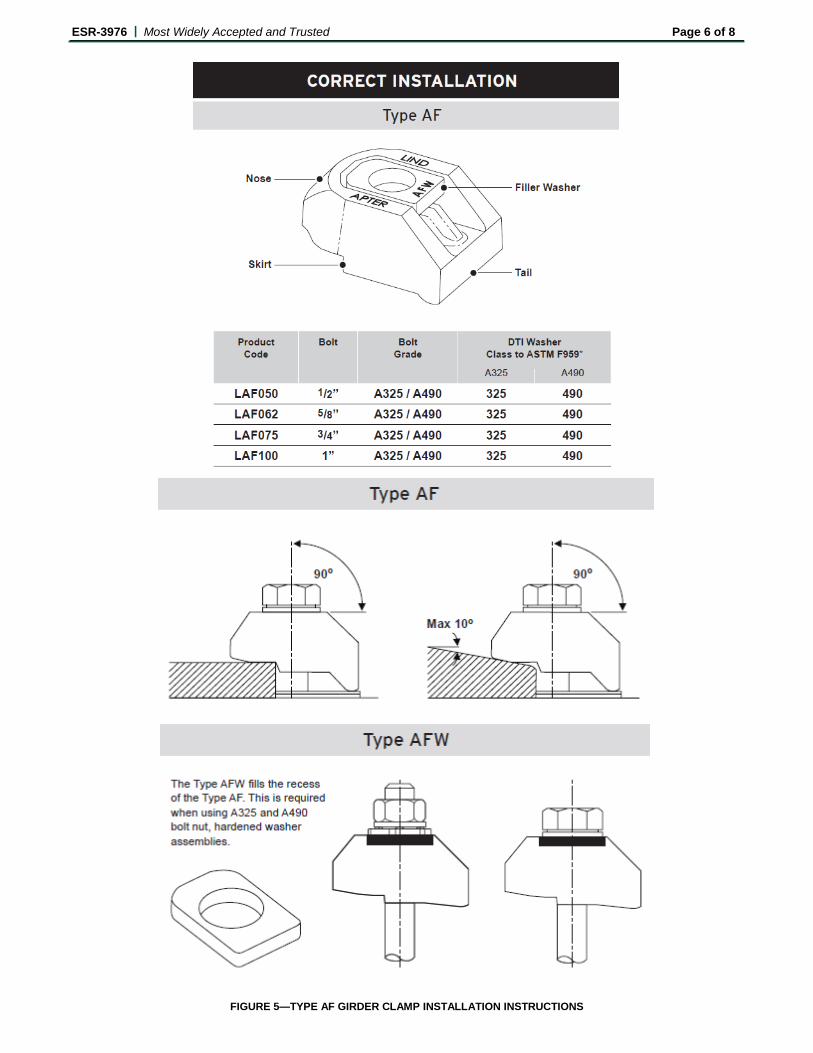
3.1 General: Lindapter Girder Clamp Assemblies consist of Type AF or Type AAF girder clamps illustrated in Figures 1 and 2, respectively; high-strength structural bolts or set screws, steel hexagon nuts, hardened steel washers and Direct Tension Indicator (DTI) washers, and are installed with either a steel location plate or a steel end plate to connect steel elements together. The Type AF girder clamp shown in Figure 5 includes a variation of the Type AF with a filler washer (Type AFW) which fills the recess of the Type AF girder clamp for use with ASTM F3125 Grade A325 and Grade A490 bolt assemblies.
A girder clamp connection includes multiples of two, typically four, replicate girder clamp assemblies. For girder clamp assemblies with a steel location plate, the girder clamp connection consists of multiples of two, typically
four, identical girder clamp assemblies, one location plate and two connected steel components. For a girder clamp assembly used with a steel end plate, the girder clamp connection consists of multiples of two, typically four, identical girder clamp assemblies, one steel end plate and the connected steel element that is to be clamped to the steel end plate. See Figures 3 and 4 for illustrations of girder clamp connections with Type AF and Type AAF girder clamps respectively. 3.2 Material: 3.2.1 Girder Clamps: Type AF and Type AAF Girder Clamps are manufactured from SG Iron complying with BS EN 1563 Grade EN-GJS-600-3 and Grade EN-GJS-400-18LT respectively, with hot dip galvanization conforming to BS EN ISO 1461 (ASTM A123). 3.2.2 High Strength Bolt Assemblies: High strength bolt assemblies consist of the following components: High-strength bolts conforming to ASTM F3125 Grade A325 galvanized or Grade A490 Geomet, matching Grade A563 F DH Heavy hexagon galvanized nuts, ASTM F436 Type 1 hardened, galvanized washers and DTI galvanized washers conforming to ASTM F959. 3.2.3 Steel Location Plates: Steel location plates are prefabricated with bolt holes and conform to ASTM A572 Grade 50 with hot dip galvanization conforming to BS EN ISO 1461 (ASTM A123). Steel location plates are located between the two steel elements to be clamped together, and are intended to keep the bolt assemblies in the correct position. Steel location plates also counter balance the forces acting on the girder clamps which are applied during tightening of the bolts. 3.2.4 Steel End Plates: Steel end plates are prefabricated with bolts holes and conform to ASTM A572 Grade 50 with hot dip galvanization conforming to BS EN ISO 1461 (ASTM A123). Steel end plates are welded to the end of one of the steel elements to be connected in accordance with AISC 360 and AWS D1.1. The steel end plate is then clamped to the second steel element. The bolt holes ensure that the structural bolt assemblies are located in the correct position. 3.2.5 Steel Packing Pieces: Steel packing pieces are structural steel plates or shims prefabricated with bolt holes and conform to BS EN 10025 with hot dip galvanization conforming to BS EN ISO 1461 (ASTM A123). Steel packing pieces are placed between the girder clamps and the steel location plates or steel end plates in order to accommodate the thickness of the connected steel element.

ESR-3976 | Most Widely Accepted and Trusted Page 2 of 8
4.0 DESIGN AND INSTALLATION 4.1 Design: The Lindapter Type AF and Type AAF Girder Clamp Assemblies are an alternative to high-strength bolt assemblies prescribed in AISC 360. The design of the girder clamp assemblies must comply with this report, Section J3 of AISC 360, and the technical data provided in Tables 1 and 2 of this report. The load carrying capacity of the girder clamp assemblies is dependent on the size and grade of the fastener assembly and type and size of the structural steel elements connected. The LRFD Design Strengths and ASD Allowable Strengths are limited by the weakest components including the connected steel elements. 4.2 Installation: The Lindapter Type AF and Type AAF Girder Clamp Assemblies must be installed in accordance with the details noted in this section, Figures 5 and 6, the manufacturer’s installation instructions and the approved plans. 4.2.1 For each girder clamp connection configuration, components not supplied by the report holder, such as the steel elements to be connected and the steel location plates or steel end plates, shall comply with the report holder’s specifications and dimensions, the requirements in this evaluation report and the approved construction documents. 4.2.2 Structural steel elements shall be aligned and in contact with the steel location plates or steel end plates as specified in this evaluation report and the approved construction documents. 4.2.3 Bolt holes shall be drilled ensuring that the resulting holes have the correct diameter and spacing according to the report holder’s specifications and drawings, and the correct design requirements for the connection. Hole sizes shall be standard diameter holes conforming to AISC 360, where the bolt hole diameters shall be no greater than the bolt diameter plus 1/16 inch (1.6 mm). 4.2.4 The girder clamps, structural steel bolts or set screws, hexagon steel nuts, hardened steel washers, steel packing pieces, steel filler washers, steel location plates or steel end plates, and steel elements to be connected shall be located in the correct positions with respect to the holes in the steel location plates or steel end plates. Installation shall follow the report holder’s recommendations to ensure that the girder clamps are in the correct orientation and that there is firm contact between the nose of the girder clamps and the connected steel elements, such as the flange of the connected steel member, and between the tail of the girder clamps and the steel location plate or steel end plate, or steel packing pieces if used. 4.2.5 DTIs that meet the requirements of AISC 348 shall be used and installed in accordance with Sections 2 and 8.2 of AISC 348. 4.3 Special Inspection: Special inspection in accordance with Sections 1705.1.1 and 1705.2 of the 2015 IBC must be performed during and after field installation of the girder clamp assemblies. The special inspector must verifying the following:
• The identification and labeling of girder clamp assemblies that are supplied by the report holder, including product name, type, grade, size, coating designation, are as specified in this evaluation report and the approved construction documents;
• Verify those components, which are not supplied by the report holder, comply with this
evaluation report, the approved construction documents, and the report holder’s instructions;
• The finish and surface condition of the steel elements are as specified in this evaluation report and the approved construction documents;
• Installations of girder clamp assemblies conform to the installation provisions in this evaluation report and the report holder’s installation instructions;
• Installed girder clamp assemblies are verified by inspections that conform to the report holder’s inspection procedures.
Where girder clamp assemblies are used for wind or seismic force resistance, special inspection shall comply with 2015 IBC Sections 1705.11, 1705.12 and 1705.13 as applicable.
5.0 CONDITIONS OF USE The Lindapter Type AF and Type AAF Girder Clamp Assemblies described in this report complies with, or are suitable alternatives to what is specified in, those codes listed in Section 1.0 of this report, subject to the following conditions:
5.1 Calculations and details justifying the use of the girder clamp assemblies is in compliance with the applicable code and this evaluation report, including showing that the girder clamp assemblies, steel location plates or steel end plates, and the connected steel elements are adequate to resist the applied loads, must be submitted to the code official for approval by the registered design professional. The calculations and details must be signed and sealed by a registered design professional when required by the statutes of the jurisdiction in which the project is to be constructed.
5.2 Steel structures utilizing girder clamp assemblies recognized in this evaluation report must be designed in accordance with the IBC, AISC 360 and this evaluation report, and must be installed in accordance with this evaluation report and the report holder’s installation instructions. In cases of a conflict between this evaluation report and the report holder’s installation instructions, the more restrictive requirement governs.
5.3 For structures regulated under the IRC, girder clamp assemblies described in this report may be used where an engineered design in accordance with IRC Section R301.1.3 is submitted to the code official for approval.
5.4 Special inspection must be provided as specified in Section 4.3 of this report.
5.5 Use of girder clamp assemblies include resistance to axial tension and slip due to load combinations that include wind loads or seismic loads, for steel structures assigned to SDCs A and B, and for structures that are assigned to SDC C, but are not part of the seismic force-resisting systems.
5.6 Use of girder clamp assemblies is limited to the individual strength values for axial tension and slip of the girder clamp connections. Resistance to combined bending moments and axial loads, combined slip and axial loads, high cycle loading (fatigue resistance) and fire resistant rating of

ESR-3976 | Most Widely Accepted and Trusted Page 3 of 8
structural steel assemblies constructed with the girder clamp connections is outside of the scope of this evaluation report.
6.0 EVIDENCE SUBMITTED Data in accordance with ICC-ES Acceptance Criteria for Girder Clamp Assemblies in Structural Steel Connections (AC469), dated June 2017.
7.0 IDENTIFICATION 7.1 The Lindapter Type AF and Type AAF Girder Clamp
packaging is labelled with the product part number, quantity, batch number, an image of the product and this evaluation report number (ESR-3976). The Type AF Girder Clamp is identified by a six character part number and the Type AAF Girder Clamp is identified by a seven character part number. The first three or four letters indicated whether the Girder Clamp Type
and the next three numbers indicate the Girder Clamp size. Each package of the Type AF and Type AAF Girder Clamp also includes the installation and safety instructions, product name, type, grade, size, coating type or designation, lot number, and the name of the report holder (Lindapter).
7.2 The report holder’s contact information is the following: LINDAPTER LINDSAY HOUSE BRACKENBECK ROAD BRADFORD, WEST YORKSHIRE BD7 2NF UNITED KINGDOM +44(0) 1274 521444 www.lindapter.com www.lindapterusa.com

ESR-3976 | Most Widely Accepted and Trusted Page 4 of 8
TABLE 1—TYPE AF GIRDER CLAMP TECHNICAL DATA PART NUMBER & DESCRIPTION DIMENSIONAL INFORMATION (inches) STATIC LOADING SEISMIC LOADING
Type LAF Part Number
Description Bolt Size (inches)
Bolt Grade
Tail length V
Y X T1 T2 Width LRFD Design Strength
ASD Allowable Strength
LRFD Design Strength
ASD Allowable Strength
Short Medium Tension lbs
Slip lbs
Tension lbs
Slip lbs
Tension lbs
Slip lbs
Tension lbs
Slip lbs
LAF050 Type AF 1/2” 1/2 A325 3/16 1/2 11/8 11/16
11/16 7/8 19/16 24054 2698 15017 1686 19513 2698 12207 1686 LAF062 Type AF 5/8” 5/8 A325 5/16 9/16 13/8 11/2
7/8 11/16 115/16 36419 5395 22773 3485 30169 5395 18884 3485 LAF075 Type AF 3/4” 3/4 A325 3/8
11/16 19/16 19/16 1 11/4 23/16 61215 8138 38262 5081 44625 8138 27921 5081 LAF100 Type AF 1” 1 A325 9/16 11/8 17/8 23/8 11/4 15/8 31/4 103272 12747 64545 7958 86709 12747 54269 7958
LAF050 Type AF 1/2” 1/2 A490 3/16 1/2 11/8 11/16 11/16 7/8 19/16 30394 4766 19019 2967 23020 4766 14410 2967 LAF062 Type AF 5/8” 5/8 A490 5/16 9/16 13/8 11/2 7/8 11/16 115/16 39746 6304 24841 3934 37183 6304 23268 3934 LAF075 Type AF 3/4” 3/4 A490 3/8 11/16 19/16 19/16 1 11/4 23/16 67420 13264 42129 8295 52605 13264 32935 8295 LAF100 Type AF 1” 1 A490 9/16 11/8 17/8 23/8 11/4 15/8 31/4 137049 18116 85655 11322 118924 18116 74434 11322
For SI: 1 inch = 25.4 mm, 1 lbf = 4.4 N.
TABLE 2—TYPE AAF GIRDER CLAMP TECHNICAL DATA
PART NUMBER & DESCRIPTION DIMENSIONAL INFORMATION (inches) STATIC LOADING SEISMIC LOADING Type LAAF Part
Number
Description Bolt Size (inches)
Bolt Grade
Clamping Range
V
Y X T Width LRFD Design Strength
ASD Allowable Strength
LRFD Design Strength
ASD Allowable Strength
Min Max Tension lbs
Slip lbs
Tension lbs
Slip lbs
Tension lbs
Slip lbs
Tension lbs
Slip lbs
LAAF050 Type AAF 1/2”
1/2 A325 3/16 1 1 – 15/16 11/16 – 115/16 11/32 – 13/8 15/8 24054 2698 15017 1686 19513 2698 12207 1686
LAAF062 Type AAF 5/8”
5/8 A325 1/4 13/16 15/16 - 2 11/4 – 25/16 13/8 – 113/16 23/16 36419 5395 22773 3485 30169 5395 18884 3485
LAAF075 Type AAF 3/4"
3/4 A325 1/4 19/16 17/8 - 31/16 115/16 – 21/2 21/16 – 21/2 3 61215 8138 38262 5081 44625 8138 27921 5081
LAAF050 Type AAF
1/2” 1/2 A490 3/16 1 1 – 15/16 11/16 – 115/16 11/32 – 13/8 15/8 30394 4766 19019 2967 23020 4766 14410 2967
LAAF062 Type AAF 5/8”
5/8 A490 1/4 13/16 15/16 - 2 11/4 – 25/16 13/8 – 113/16 23/16 39746 6304 24841 3934 37183 6304 23268 3934
LAAF075 Type AAF 3/4"
3/4 A490 1/4 19/16 17/8 - 31/16 115/16 – 21/2 21/16 – 21/2 3 67420 13264 42129 8295 52605 13264 32935 8295
For SI: 1 inch = 25.4 mm, 1 lbf = 4.4 N.

ESR-3976 | Most Widely Accepted and Trusted Page 5 of 8
FIGURE 1—TYPE AF GIRDER CLAMP FIGURE 2—TYPE AAF GIRDER CLAMP
FIGURE 4—GIRDER CLAMP CONNECTION WITH LOCATION PLATE (TYPE AAF SHOWN)
FIGURE 3—GIRDER CLAMP CONNECTION WITH END PLATE (TYPE AF SHOWN)
ESR-3976 | Most Widely Accepted and Trusted Page 6 of 8
FIGURE 5—TYPE AF GIRDER CLAMP INSTALLATION INSTRUCTIONS

ESR-3976 | Most Widely Accepted and Trusted Page 7 of 8
If the rocking washer top face is not at 90° to the bolt then the installation is incorrect. Ensure that the nose of the Type AAF Girder Clamp is in contact with the flange of the section being clamped. The Type AAF Girder Clamp may be used on parallel and tapered flanges up to 10°.
FIGURE 6—TYPE AAF GIRDER CLAMP INSTALLATION INSTRUCTIONS

ESR-3976 | Most Widely Accepted and Trusted Page 8 of 8
FIGURE 7—TYPICAL GIRDER CLAMP ASSEMBLIES INSTALLED IN SLIP AND TENSILE CONNECTIONS

To verify correct installation including use in seismic or wind loading applications in accordance with the 2012 and 2015 International Building Code Sections 1705.1, 1705.2, 1704.3 and 1705, please refer to the following instructions, and those referenced in AISC 360-10 section N5-6 and the RCSC Specification for Structural Joints Using High-Strength Bolts.
Inspection prior to installation...• There are no gaps between the connecting steelwork.• Ensure all components are of correct size and specification. Only bolts of grades A325 or A490 are to be used.• The location plate or end plate is of the correct dimensions and material in accordance with the Lindapter website or a Lindapter connection detail drawing.• The holes are the correct diameter, conforming to AISC 360 and are positioned in accordance with the Lindapter website for location plates and end plates.• The connecting steelwork is plain or galvanised. • Verify that the correct type and number of packing pieces relative to the clamping thickness, as per Lindapter’s website or a Lindapter connection detail drawing, are used within the assembly.
Inspection during installation...• Assemble the girder clamp assembly as instructed. Ensure the DTI arches are braced against the hardened bearing surface of the nut, bolt or washer. For more instruction on the usage of DTI washers refer to the RCSC Specification for Structural Joints Using High-Strength Bolts and the DTI washer manufacturer’s instructions.• Ensure the top surface of the clamp and the bolt head are parallel to the steel work. Packing pieces are used to level the clamp.• Use a bolt tightening sequence that ensures even preload and is in accordance with the relevant standards.• Ensure that the DTI washers are activated in accordance with the manufacturer’s instruction.
Inspection after installation...• There are no gaps between the connecting steel work.• Bolt heads and the top surface of the clamps are parallel to the location plate/end plate.• The DTIs are activated in accordance to the manufacturer’s instruction.• Verify that the correct type and number of packing pieces relative to the clamping thickness, as per Lindapter’s website or a Lindapter connection detail drawing, are used within the assembly.
®
Contact Lindapter Technical Support for more information: 866 566-2658 (BOLT) | [email protected] | www.LindapterUSA.com
As required by:
Ref: SIDGC_MAR19
Type AF and Type AAFSpecial Inspection Document to comply with ICC-ES ESR 3976
ICC
ESR-3976

Nut (ASTM A563)
Hardened Washer (ASTM F436)
DTI Washer (ASTM F959)
Type AFW Filler Washer
Type AF
Packing Piece(if required)
Location Plate
Packing Piece(if required)
Type AF
Type AFW Filler Washer
Hardened Washer (ASTM F436)
Bolt (ASTM A325 / A490)
Nut (ASTM A563)
Hardened Washer (ASTM F436)
DTI Washer (ASTM F959)
Type AFW Filler Washer
Type AF
Packing Piece(if required)
End Plate
Hardened Washer (ASTM F436)
Bolt (ASTM A325 / A490)
Contact Lindapter Technical Support for more information: 866 566-2658 (BOLT) | [email protected] | www.LindapterUSA.com
Type AF Installation when using a Location Plate in accordance to ICC-ES ESR 3976
Type AF Installation when using an End Plate in accordance to ICC-ES ESR 3976

Type AAF Installation when using a Location Plate in accordance to ICC-ES ESR 3976
Contact Lindapter Technical Support for more information: 866 566-2658 (BOLT) | [email protected] | www.LindapterUSA.com
Nut (ASTM A563)
Hardened Washer (ASTM F436)
DTI Washer (ASTM F959)
Type AAF with Rocking Washer
Location Plate
Type AAF with Rocking Washer
Hardened Washer (ASTM F436)
Bolt (ASTM A325 / A490)
Nut (ASTM A563)
Hardened Washer (ASTM F436)
DTI Washer (ASTM F959)
Type AAF with Rocking Washer
End Plate
Hardened Washer (ASTM F436)
Bolt (ASTM A325 / A490)
Rocking washer to be parallel to the location plate
Rocking washer to be parallel to the location plate
Type AAF Installation when using an End Plate in accordance to ICC-ES ESR 3976

Filler Washer
Product Code Bolt Bolt Grade DTI Washer Class to ASTM F959*
A325 A490
LAF050 1/2” A325 / A490 325 490
LAF062 5/8” A325 / A490 325 490
LAF075 3/4” A325 / A490 325 490
LAF100 1” A325 / A490 325 490
* Only assemblies utilising a DTI washer are subject to ICC-ES approval. For torque values and alternative bolt grades please contact Lindapter.
Skirt
Rocking Washer
Product Code Bolt Bolt Grade DTI Washer Class to ASTM F959* Clamping Range
A325 A490 Min Min
LAAF050 1/2” A325 / A490 325 490 3/16” 1”
LAAF062 5/8” A325 / A490 325 490 1/4” 1 3/16”
LAAF075 3/4” A325 / A490 325 490 1/4” 1 9/16”
Tail
Nose
Type AF Installation Data
Type AAF Installation Data
* Only assemblies utilising a DTI washer are subject to ICC-ES approval. For torque values and alternative bolt grades please contact Lindapter.
Contact Lindapter Technical Support for more information: 866 566-2658 (BOLT) | [email protected] | www.LindapterUSA.com
Tail
Nose