icc-es evaluation report esr-2583*
TRANSCRIPT
ICC-ES Evaluation Reports are not to be construed as representing aesthetics or any other attributes not specifically addressed, nor are they to be construed as an endorsement of the subject of the report or a recommendation for its use. There is no warranty by ICC Evaluation Service, LLC, express or implied, as to any finding or other matter in this report, or as to any product covered by the report.
Copyright © 2013 Page 1 of 18 1000
ICC-ES Evaluation Report ESR-2583* Reissued December 1, 2011 This report is subject to renewal December 1, 2013.
www.icc-es.org | (800) 423-6587 | (562) 699-0543 A Subsidiary of the International Code Council ®
DIVISION: 03 00 00—CONCRETE Section: 03 16 00—Concrete Anchors
DIVISION: 05 00 00—METALS Section: 05 05 19—Post-Installed Concrete Anchors
REPORT HOLDER:
POWERS FASTENERS, INC. 2 POWERS LANE BREWSTER, NEW YORK 10509 (914) 235-6300 or (800) 524-3244 www.powers.com [email protected]
ADDITIONAL LISTEE:
DEWALT (STANLEY BLACK & DECKER) 701 EAST JOPPA ROAD TOWSON, MARYLAND 21286 (800) 433-9258 www.dewalt.com
EVALUATION SUBJECT:
POWERS PE1000+® EPOXY ADHESIVE ANCHOR SYSTEM IN CRACKED AND UNCRACKED CONCRETE
1.0 EVALUATION SCOPE
Compliance with the following codes:
2009, 2006 and 2003 International Building Code® (IBC)
2009, 2006 and 2003 International Residential Code® (IRC)
Property evaluated:
Structural
2.0 USES
2.1 General:
The Powers PE1000+ epoxy adhesive anchors are used to resist static, wind or earthquake (IBC Seismic Design Categories A through F) tension and shear loads in cracked and uncracked normal-weight concrete with 1/2-, 5/8-,
3/4-, 7/8-, 1-, and 11/4-inch-diameter (12.7, 15.9, 19.1,
22.2, 25.4 and 31.8 mm) threaded steel rods and No. 4 through No. 10 steel reinforcing bars in hammer-drilled holes.
The anchors are used to resist static, wind or earthquake (IBC Seismic Design Categories A and B only) tension and shear loads in uncracked normal-weight concrete only with 3/8-inch-diameter (9.5 mm) threaded steel rods and No. 3 steel reinforcing bars in hammer-drilled holes, and
uncracked normal-weight concrete only with 1/2-, 5/8-,
3/4-, 7/8- and 1-inch-diameter (12.7, 15.9, 19.1, 22.2 and 25.4 mm) threaded steel rods and No. 4 through No. 8 steel reinforcing bars in core drilled holes. Use is limited to normal-weight concrete with a specified compressive strength, f′c, of 2,500 psi to 8,500 psi (17.2 MPa to 58.6 MPa).
The anchor system is an alternative to cast-in-place anchors described in Sections 1911 and 1912 of the 2009 and 2006 IBC, and Sections 1912 and 1913 of the 2003 IBC. The anchor systems may also be used where an engineered design is submitted in accordance with Section R301.1.3 of the 2009, 2006 and 2003 IRC.
3.0 DESCRIPTION
3.1 General:
The Powers PE1000+ Epoxy Adhesive Anchor System is comprised of a two-component epoxy adhesive provided in cartridges, static mixing nozzles, dispensing tools, hole cleaning equipment and adhesive injection accessories.
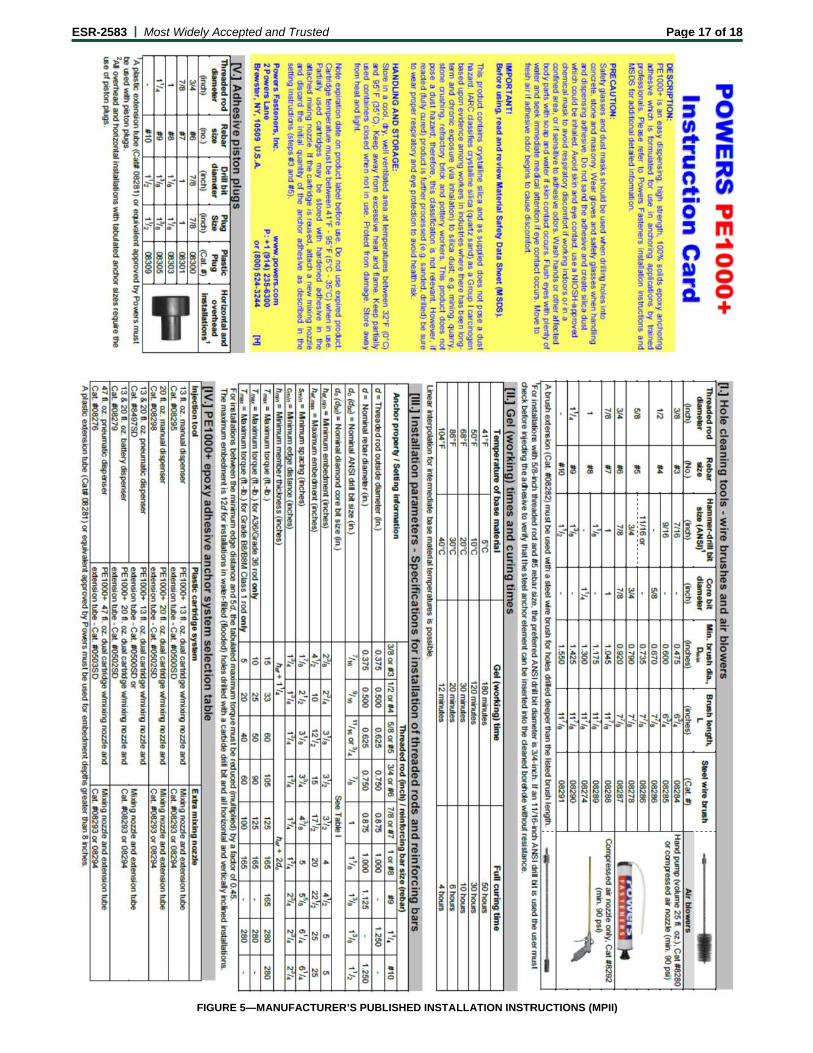
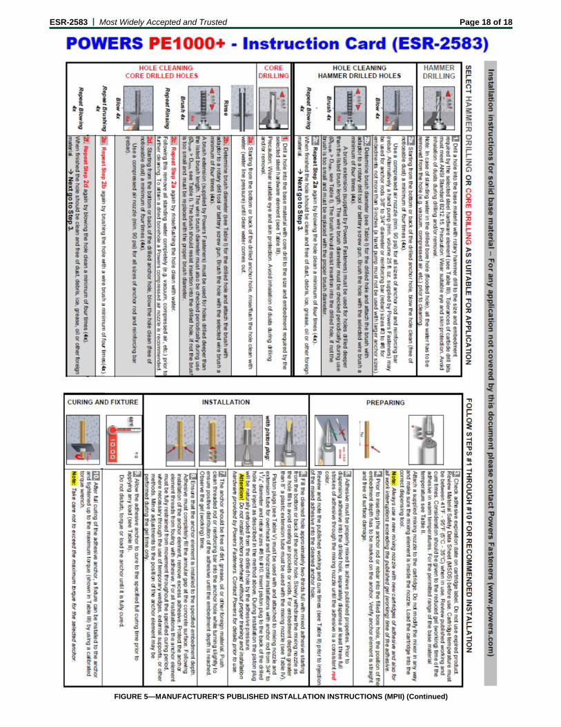
Product names for the report holder and the additional listee are presented in Table A of this report. Powers PE1000+ epoxy adhesive may be used with continuously threaded steel rods or deformed steel reinforcing bars. The primary components of the Powers PE1000+ Epoxy Adhesive Anchor System, including the epoxy adhesive cartridge, static mixing nozzle, the nozzle extension tube, dispensing tool and typical steel anchor elements, are shown in Figure 3 of this report. Manufacturer’s published installation instructions (MPII) and parameters, as included with each adhesive unit package, are replicated in Figure 5 of this report.
3.2 Materials:
3.2.1 PE1000+ Epoxy Adhesive: PE1000+ epoxy adhesive is an injectable two-component epoxy. The two components are separated by means of a labeled dual-cylinder cartridge. The two components combine and react when dispensed through a static mixing nozzle, supplied by Powers Fasteners, which is attached to the cartridge. A nozzle extension tube is also packaged with the cartridge. The PE1000+ epoxy adhesive is available in 13-ounce (385 mL), 20-ounce (585 mL), and 47-ounce (1400 mL) cartridges. Each cartridge label is marked with the adhesive expiration date. The shelf life, as indicated by the expiration date, applies to an unopened cartridge when stored in accordance with Figure 5.
3.2.2 Hole Cleaning Equipment: Hole cleaning equipment is comprised of steel wire brushes and an air pump supplied by Powers Fasteners, Inc., and a
*Revised May 2013
ESR-2583 | Most Widely Accepted and Trusted Page 2 of 18
compressed air nozzle. The equipment is shown in Figure 5 of this report.
3.2.3 Dispensers: PE1000+ epoxy adhesive must be dispensed with manual, pneumatic dispensers, or electric powered dispensers supplied by Powers Fasteners, Inc.
3.2.4 Steel Anchor Elements:
3.2.4.1 Threaded Steel Rods: Threaded steel rods must be clean and continuously threaded (all-thread) in diameters as described in Table 4 and Figure 5 of this report. Specifications for grades of threaded rod, including the mechanical properties and corresponding nuts and washers, are listed in Table 2 of this report. Carbon steel threaded rods must be furnished with a minimum 0.0002-inch-thick (0.005 mm) zinc electroplated coating complying with ASTM B633, SC1; or a minimum 0.0021-inch-thick (0.053 mm) mechanically deposited zinc coating complying with ASTM B695, Class 55; or a hot dip galvanized zinc coating complying with ASTM A153, Class C or D. The stainless steel threaded rods must comply with Table 2 of this report. Steel grades and material types (carbon, stainless) of the washers and nuts must be matched to the threaded rods. Threaded steel rods must be straight and free of indentations or other defects along their length. The embedded end may be either flat cut or cut on the bias to a chisel point.
3.2.4.2 Steel Reinforcing Bars: Steel reinforcing bars are deformed reinforcing bars (rebars). Table 5 and Figure 5 of this report summarize reinforcing bar size ranges. Table 3 summarizes specifications of permitted reinforcing bar types and grades. The embedded portions of reinforcing bars must be clean, straight, and free of mill scale, rust, debris and other coatings (other than zinc) that may impair the bond with the adhesive. Reinforcing bars must not be bent after installation, except as set forth in Section 7.3.2 of ACI 318, with the additional condition that the bars must be bent cold, and heating of the reinforcing bars to facilitate field bending is not permitted.
3.2.4.3 Ductility: In accordance with ACI 318 Appendix D, in order for a steel anchor element to be considered ductile, the tested elongation must be at least 14 percent and the reduction of area must be at least 30 percent. Steel elements with a tested elongation of less than 14 percent or a reduction of area less than 30 percent, or both, are considered brittle. Values for various steel materials are provided in Tables 2 and 3 of this report. Where values are nonconforming or unstated, the steel element must be considered brittle, unless evidence otherwise is shown to the satisfaction of the registered design professional and the code official.
3.3 Concrete:
Normal-weight concrete must comply with Sections 1903 and 1905 of the IBC, as applicable.
4.0 DESIGN AND INSTALLATION
4.1 Strength Design:
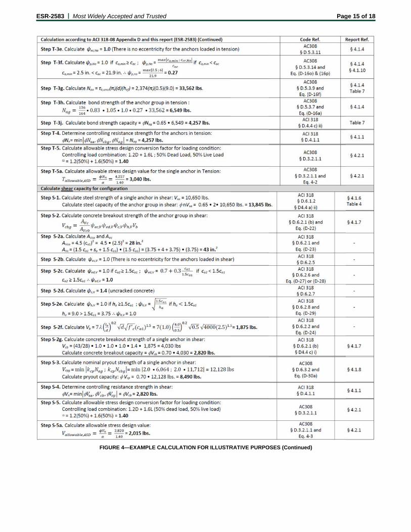
4.1.1 General: The design strength of anchors under the 2009 and 2003 IBC, as well as Section 301.1.3 of the 2009 and 2003 IRC, must be determined in accordance with ACI 318-08 Appendix D and this report. The design strength of anchors under the 2006 IBC and 2006 IRC must be determined in accordance with ACI 318-05 Appendix D and this report. An example set of calculations in accordance with the 2009 IBC (ACI 318-08) is presented in Figure 4 of this report. The anchor design must satisfy the requirements in ACI 318, D.4.1.1 and D.4.1.2, except as required in ACI 318 D.3.3.
Design parameters, including strength reduction factors, , corresponding to each limit state and steel anchor element, are provided in Table 4 through Table 8 of this report. Design parameters are based on the 2009 IBC (ACI 318-08) unless noted otherwise in Sections 4.1.1 through 4.1.12. Strength reduction factors, , as described in ACI 318 D.4.4 must be used for load combinations calculated in accordance with Section 1605.2 of the IBC, or ACI 318 Section 9.2. Strength reduction factors, , as described in ACI 318 D.4.5 must be used for load combinations calculated in accordance with ACI 318 Appendix C.
The following provides amendments to ACI 318 Appendix D as required for the strength design of adhesive anchors in hardened concrete. In conformance with ACI 318, all equations are expressed in inch-pound units.
Modify ACI 318 D.4.1.2 as follows:
D.4.1.2—In Eq. (D-1) and (D-2), Nn and Vn are the lowest design strengths determined from all appropriate failure modes. Nn is the lowest design strength in tension of an anchor or group of anchors as determined from consideration of Nsa, either Na or Nag, and either Ncb or Ncbg. Vn is the lowest design strength in shear of an anchor or a group of anchors as determined from consideration of Vsa, either Vcb or Vcbg, and either Vcp or Vcpg. For adhesive anchors subjected to tension resulting from sustained loading, refer to D.4.1.4 in this report for additional requirements.
Add ACI 318 D.4.1.4 as follows:
D.4.1.4—For adhesive anchors subjected to tension resulting from sustained loading, a supplementary design check shall be performed using Eq. (D-1) whereby Nua is determined from the sustained load alone, e.g., the dead load and that portion of the live load acting that may be considered as sustained and Nn is determined as follows:
D.4.1.4.1—For single anchors, Nn = 0.75Na0.
D.4.1.4.2—For anchor groups, Eq. (D-1) shall be satisfied by taking Nn = 0.75Na0 for that anchor in an anchor group that resists the highest tension load.
D.4.1.4.3—Where shear loads act concurrently with the sustained tension load, interaction of tension and shear shall be analyzed in accordance with D.4.1.3.
Modify ACI 318 D.4.2.2 in accordance with 2009 IBC Section 1908.1.10 as follows:
D.4.2.2 – The concrete breakout strength requirements for anchors in tension shall be considered satisfied by the design procedure of D.5.2 provided Equation D-8 is not used for the anchor embedments exceeding 25 inches. The concrete breakout strength requirements for anchors in shear with diameters not exceeding 2 inches shall be considered satisfied by the design procedure of D.6.2. For anchors in shear with diameter exceeding 2 inches, shear anchor reinforcement shall be provided in accordance with the procedure of D.6.2.9.
4.1.2 Static Steel Strength in Tension, Nsa: The nominal static steel strength of a single anchor in tension, Nsa, in accordance with ACI 318 D.5.1.2, is given in Tables 4 and 5 of this report for the corresponding steel anchor element.
4.1.3 Static Concrete Breakout Strength in Tension, Ncb or Ncbg: The nominal static concrete breakout strength of a single anchor or group of anchors in tension, Ncb or Ncbg, must be calculated in accordance with ACI 318 D.5.2 with the following additions:
ESR-2583 | Most Widely Accepted and Trusted Page 3 of 18
D.5.2.10 (2009 IBC) or D.5.2.9 (2006 IBC)—The limiting concrete strength of adhesive anchors in tension shall be calculated in accordance with D.5.2.1 to D.5.2.9 under the 2009 IBC or D.5.2.1 to D.5.2.8 under the 2006 IBC, where the value of kc to be used in Eq. (D-7) shall be:
kc,cr where analysis indicates cracking at service load levels in the anchor vicinity (cracked concrete). The values of kc,cr are given in Table 6 of this report.
kc,uncr where analysis indicates no cracking (ft < fr) at service load levels in the anchor vicinity (uncracked concrete). The values of kc,uncr are given in Table 6 of this report.
The basic concrete breakout strength of a single anchor in tension, Nb, must be calculated in accordance with ACI 318 D.5.2.2 using the actual values of hef and kc,cr or kc,uncr as given in the tables of this report. The value of f′c must be limited to a maximum of 8,000 psi (55.2 MPa), in accordance with ACI 318 D.3.5. The modification factor “” shall be taken as 1.0. Anchors shall not be installed in lightweight concrete. Additional information for the determination of the nominal concrete breakout strength is given in Table 6 of this report for the corresponding steel anchor element.
4.1.4 Static Pullout Strength in Tension: In lieu of determining the nominal static pullout strength in accordance with ACI 318 D.5.3, nominal static bond strength in tension must be calculated in accordance with the following sections added to ACI 318:
D.5.3.7—The nominal bond strength of a single adhesive anchor, Na, or group of adhesive anchors, Nag, in tension shall not exceed:
For a single anchor
0
0aNap,Naed,
Na
Naa N
A
AN (D-16a)
For a group of anchors
0aNap,Naec,Nag,Naed,
Na
Naag N
A
AN
0
(D-16b)
where:
ANa is the projected area of the failure surface for the single anchor or group of anchors that shall be approximated as the base of the rectilinear geometrical figure that results from projecting the failure surface outward a distance, ccr,Na, from the centerline of the anchor, or in the case of a group of anchors, from a line through a row of adjacent anchors. ANa shall not exceed nANa0 where n is the number of anchors in tension in the group. In ACI 318 Figures RD.5.2.1a and RD.5.2.1b, the terms 1.5hef and 3.0hef shall be replaced with ccr,Na and scr,Na, respectively.
ANa0 is the projected area of the failure surface of a single anchor without the influence of proximate edges in accordance with Eq. (D-16c).
2Nacr,Na sA 0
(D-16c)
with
scr,Na = as given by Eq. (D-16d)
D.5.3.8—The critical spacing and critical edge distance shall be calculated as follows:
ef
uncrk,Nacr, hds 3
450120
,
(D-16d)
2
Nacr,Nacr,
sc (D-16e)
D.5.3.9—The basic strength of a single adhesive anchor in tension in cracked concrete shall not exceed:
efcrk,a hdN 0
(D-16f)
D.5.3.10—The modification factor for the influence of the failure surface of a group of adhesive anchors is:
Na0g,
Nacr,Na0g,Nag, s
s 1
50.
(D-16g)
where
011
51
0 .
.
crmax,k,
crk,Nag, nn
(D-16h)
and where
n = The number of tension-loaded adhesive anchors in a group.
cef
crc,crmax,k, fh
d
k´
(D-16i)
The value of f′c must be limited to 8,000 psi (55.2 MPa), maximum, in accordance with ACI 318 D.3.5.
D.5.3.11—The modification factor for eccentrically loaded adhesive anchor groups is:
01
21
1.
´
Nacr,
NNaec,
s
e
(D-16j)
Eq. (D-16j) is valid for 2
se n ´
If the loading on an anchor group is such that only certain anchors are in tension, only those anchors that are in tension shall be considered when determining the eccentricity, e´N, for use in Eq. (D-16j).
In the case where eccentric loading exists about two orthogonal axis, the modification factor ψec,Na shall be computed for each axis individually and the product of these factors used as ψec,Na in Eq. (D-16b).
D.5.3.12—The modification factor for the edge effects for a single adhesive anchor or a group of adhesive anchors loaded in tension is:
for Nacr,mina, cc (D-16l)
01.Naed,
or
for Nacr,mina, cc (D-16m)
0.13.07.0
Nacr,
mina,Naed, c
c
D.5.3.13—When an adhesive anchor or a group of adhesive anchors is located in a region of a concrete member where analysis indicates no cracking at service load levels, the nominal strength Na or Nag of a single adhesive anchor or a group of adhesive anchors shall be calculated according to Eq. (D-16a) and Eq. (D-16b) with k,uncr substituted for k,cr in the calculation of the basic strength Na0 in accordance with Eq. (D-16f). The factor Ψg,Na0 shall be calculated in accordance with Eq. (D-16h)
ESR-2583 | Most Widely Accepted and Trusted Page 4 of 18
whereby the value of k,max,uncr shall be calculated in accordance with Eq. (D-16n) and substituted for k,max,cr in Eq. (D-16h).
cef
uncrc,uncrmax,k, fh
d
k´
(D-16n)
The value of f′c must be limited to a maximum of 8,000 psi (55.2 MPa) in accordance with ACI 318 D.3.5.
D.5.3.14—When an adhesive anchor or a group of adhesive anchors is located in a region of a concrete member where analysis indicates no cracking at service load levels, the modification factor shall be taken as:
0.1Nap,ψ when acmina, cc (D-16o)
ac
Nacr,mina,Nap, c
ccmaxψ
; when
acmina, cc (D-16p)
where:
cac shall be determined in accordance with Section 4.1.10 of this report.
For all other cases, Ψp,Na = 1.0 (e.g. when cracked concrete is considered).
Additional information for the determination of nominal bond strength in tension is given in Section 4.1.5 and Tables 7 and 8 of this report.
4.1.5 Bond Strength Determination: Bond strength values are a function of concrete compressive strength, concrete state (cracked, uncracked), drilling method (hammer-drill, core drilling) and installation conditions (dry concrete, water-saturated concrete, water-filled holes). Special inspection level is periodic except as noted in Section 4.4 of this report.
Bond strength values must be modified with the factor κnn for cases where holes are drilled in water-saturated concrete (κws) or where the holes are water-filled at the time of anchor installation (κwf), as follows:
CONCRETE
STATE
DRILLING METHOD
PERMISSIBLE
INSTALLATION
CONDITIONS
BOND
STRENGTH
ASSOCIATED
STRENGTH
REDUCTION FACTOR
Cracked Hammer-
drill
Dry concrete k,cr d
Water-saturated concrete k,cr · κws ws
Water-filled hole
(flooded) k,cr · κwf wf
Uncracked Hammer-
drill
Dry concrete k,uncr d
Water-saturated concrete k,uncr · κws ws
Water-filled hole
(flooded) k,uncr · κwf wf
Uncracked Core drill
Dry concrete k,uncr d
Water-saturated concrete k,uncr · κws ws
Water-filled hole
(flooded) k,uncr · κwf wf
The bond strength values in Table 7 for hammer-drilled holes and in Table 8 for core drilled holes, correspond to concrete compressive strength f′c equal to 2,500 psi (17.2 MPa). For concrete compressive strength, f′c between 2,500 psi and 8,000 psi (17.2 MPa and 55.2 MPa), the tabulated characteristic bond strength may be increased by a factor of (f′c / 2,500)0.12 [For SI: (f′c / 17.2)0.12]. Where applicable, the modified bond strength values must be used in lieu of k,cr and k,uncr in Equations (D-16d), (D-16f) and (D-16h). The resulting nominal bond strength must be multiplied by the associated strength reduction factor nn.
4.1.6 Static Steel Strength in Shear, Vsa: The nominal static steel strength of a single anchor in shear, Vsa, in accordance with ACI 318 D.6.1.2 is given in Tables 4 and 5 of this report for the corresponding anchor steel.
4.1.7 Static Concrete Breakout Strength in Shear, Vcb or Vcbg: The nominal static concrete breakout strength in shear of a single adhesive anchor or a group of adhesive anchors, Vcb or Vcbg, respectively, must be calculated in accordance with ACI 318 D.6.2 based on information given in Table 6 of this report. The basic concrete breakout strength in shear of a single anchor in cracked concrete, Vb, must be calculated in accordance with ACI 318 D.6.2.2 using the value of d given in Tables 4 and 5 of this report in lieu of da (2009 IBC) and do (2006 IBC). In addition, hef must be substituted for ℓe. In no case shall hef exceed 8d. The value of f′c must be limited to a maximum of 8,000 psi (55.2 MPa), in accordance with ACI 318 D.3.5.
4.1.8 Static Concrete Pryout Strength in Shear: In lieu of determining the nominal static pryout strength in shear in accordance with ACI 318 D.6.3.1, the nominal pryout strength must be calculated in accordance with the following sections added to ACI 318:
D.6.3.2—The nominal pryout strength of an adhesive anchor or group of adhesive anchors shall not exceed:
(a) for a single adhesive anchor:
cbcpacpcp NkNk minV ; (D-30a)
(b) for a group of adhesive anchors:
cbgcpagcpcpg NkNk minV ; (D-30b)
where:
kcp = 1.0 for hef < 2.5 inches (64 mm)
kcp = 2.0 for hef ≥ 2.5 inches (64 mm)
Na shall be calculated in accordance with Eq. (D-16a)
Nag shall be calculated in accordance with Eq. (D-16b)
Ncb and Ncbg are determined in accordance with D.5.2.1
4.1.9 Minimum Member Thickness hmin, Anchor Spacing smin, Edge Distance cmin: In lieu of ACI 318 D.8.1 and D.8.3, values of cmin and smin described in this report must be observed for anchor design and installation. Likewise, in lieu of ACI 318 D.8.5, the minimum member thicknesses, hmin, described in this report must be observed for anchor design and installation. In determining minimum edge distance, cmin, the following section must be added to ACI 318:
D.8.8—For adhesive anchors that will remain untorqued after installation, the minimum edge distance shall be based on minimum cover requirements for reinforcement in 7.7. For adhesive anchors that will be torqued during installation, the minimum edge distance and spacing distances are given in Table 6 and Figure 5 of this report.
ESR-2583 | Most Widely Accepted and Trusted Page 5 of 18
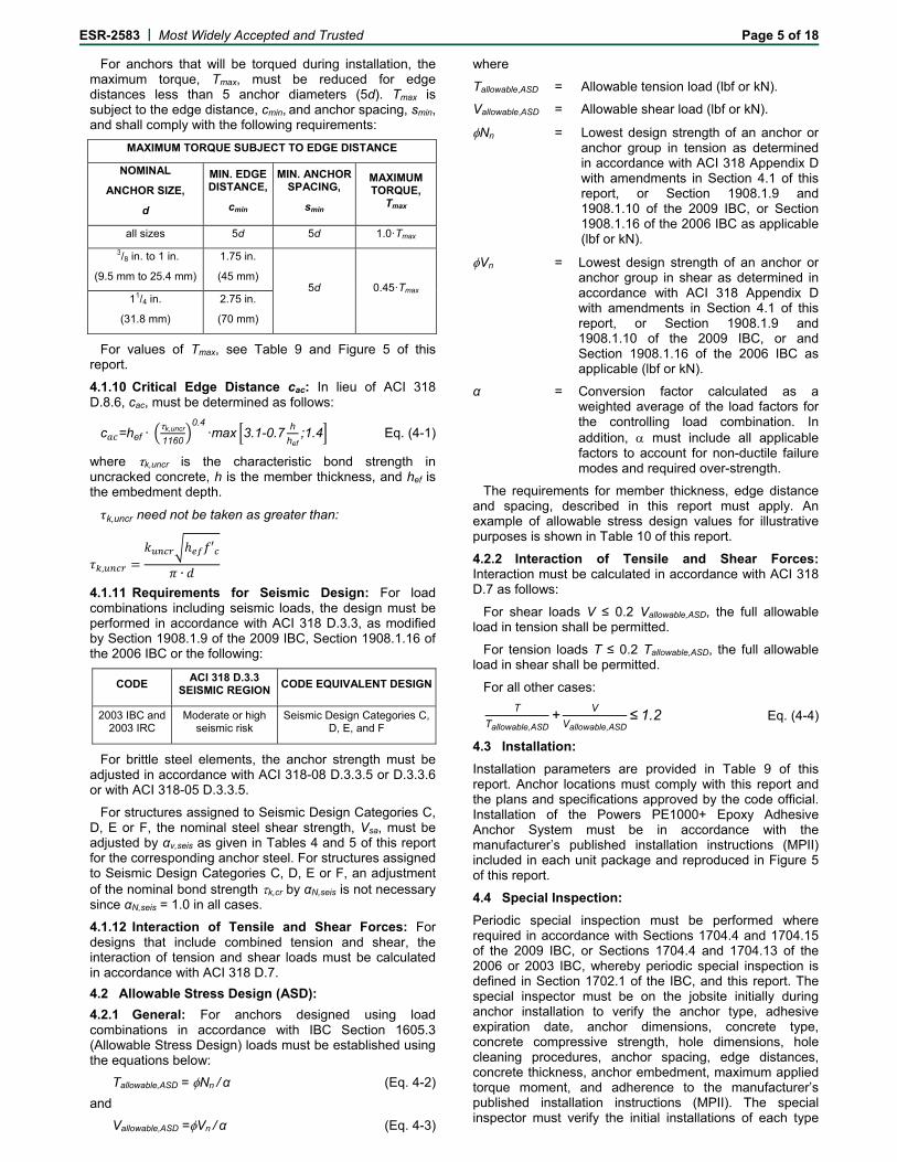
For anchors that will be torqued during installation, the maximum torque, Tmax, must be reduced for edge distances less than 5 anchor diameters (5d). Tmax is subject to the edge distance, cmin, and anchor spacing, smin, and shall comply with the following requirements:
MAXIMUM TORQUE SUBJECT TO EDGE DISTANCE
NOMINAL
ANCHOR SIZE,
d
MIN. EDGE DISTANCE,
cmin
MIN. ANCHOR SPACING,
smin
MAXIMUM TORQUE,
Tmax
all sizes 5d 5d 1.0·Tmax
3/8 in. to 1 in.
(9.5 mm to 25.4 mm)
1.75 in.
(45 mm) 5d 0.45·Tmax
11/4 in.
(31.8 mm)
2.75 in.
(70 mm)
For values of Tmax, see Table 9 and Figure 5 of this report.
4.1.10 Critical Edge Distance cac: In lieu of ACI 318 D.8.6, cac, must be determined as follows:
c =hef·τk,uncr
1160
0.4·max 3.1-0.7
h
hef;1.4 Eq. (4-1)
where τk,uncr is the characteristic bond strength in uncracked concrete, h is the member thickness, and hef is the embedment depth.
k,uncr need not be taken as greater than:
,
′
∙
4.1.11 Requirements for Seismic Design: For load combinations including seismic loads, the design must be performed in accordance with ACI 318 D.3.3, as modified by Section 1908.1.9 of the 2009 IBC, Section 1908.1.16 of the 2006 IBC or the following:
CODE ACI 318 D.3.3
SEISMIC REGION CODE EQUIVALENT DESIGN
2003 IBC and 2003 IRC
Moderate or high seismic risk
Seismic Design Categories C, D, E, and F
For brittle steel elements, the anchor strength must be adjusted in accordance with ACI 318-08 D.3.3.5 or D.3.3.6 or with ACI 318-05 D.3.3.5.
For structures assigned to Seismic Design Categories C, D, E or F, the nominal steel shear strength, Vsa, must be adjusted by αv,seis as given in Tables 4 and 5 of this report for the corresponding anchor steel. For structures assigned to Seismic Design Categories C, D, E or F, an adjustment of the nominal bond strength k,cr by αN,seis is not necessary since αN,seis = 1.0 in all cases.
4.1.12 Interaction of Tensile and Shear Forces: For designs that include combined tension and shear, the interaction of tension and shear loads must be calculated in accordance with ACI 318 D.7.
4.2 Allowable Stress Design (ASD):
4.2.1 General: For anchors designed using load combinations in accordance with IBC Section 1605.3 (Allowable Stress Design) loads must be established using the equations below:
Tallowable,ASD = Nn / α (Eq. 4-2)
and
Vallowable,ASD =Vn / α (Eq. 4-3)
where
Tallowable,ASD = Allowable tension load (lbf or kN).
Vallowable,ASD = Allowable shear load (lbf or kN).
Nn = Lowest design strength of an anchor or anchor group in tension as determined in accordance with ACI 318 Appendix D with amendments in Section 4.1 of this report, or Section 1908.1.9 and 1908.1.10 of the 2009 IBC, or Section 1908.1.16 of the 2006 IBC as applicable (lbf or kN).
Vn = Lowest design strength of an anchor or anchor group in shear as determined in accordance with ACI 318 Appendix D with amendments in Section 4.1 of this report, or Section 1908.1.9 and 1908.1.10 of the 2009 IBC, or and Section 1908.1.16 of the 2006 IBC as applicable (lbf or kN).
α = Conversion factor calculated as a weighted average of the load factors for the controlling load combination. In addition, must include all applicable factors to account for non-ductile failure modes and required over-strength.
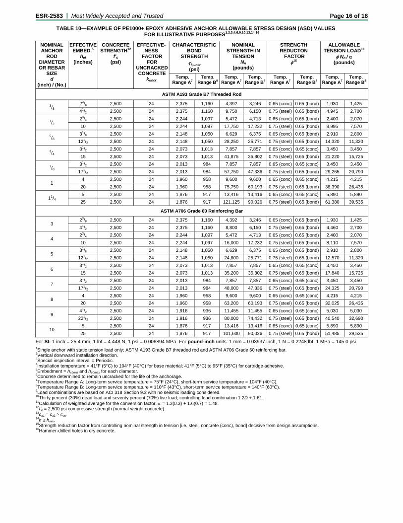
The requirements for member thickness, edge distance and spacing, described in this report must apply. An example of allowable stress design values for illustrative purposes is shown in Table 10 of this report.
4.2.2 Interaction of Tensile and Shear Forces: Interaction must be calculated in accordance with ACI 318 D.7 as follows:
For shear loads V ≤ 0.2 Vallowable,ASD, the full allowable load in tension shall be permitted.
For tension loads T ≤ 0.2 Tallowable,ASD, the full allowable load in shear shall be permitted.
For all other cases:
T
Tallowable,ASD+
V
Vallowable,ASD≤1.2 Eq. (4-4)
4.3 Installation:
Installation parameters are provided in Table 9 of this report. Anchor locations must comply with this report and the plans and specifications approved by the code official. Installation of the Powers PE1000+ Epoxy Adhesive Anchor System must be in accordance with the manufacturer’s published installation instructions (MPII) included in each unit package and reproduced in Figure 5 of this report.
4.4 Special Inspection:
Periodic special inspection must be performed where required in accordance with Sections 1704.4 and 1704.15 of the 2009 IBC, or Sections 1704.4 and 1704.13 of the 2006 or 2003 IBC, whereby periodic special inspection is defined in Section 1702.1 of the IBC, and this report. The special inspector must be on the jobsite initially during anchor installation to verify the anchor type, adhesive expiration date, anchor dimensions, concrete type, concrete compressive strength, hole dimensions, hole cleaning procedures, anchor spacing, edge distances, concrete thickness, anchor embedment, maximum applied torque moment, and adherence to the manufacturer’s published installation instructions (MPII). The special inspector must verify the initial installations of each type

ESR-2583 | Most Widely Accepted and Trusted Page 6 of 18
and size of adhesive anchor by construction personnel on the site. Subsequent installations of the same anchor type and size by the same construction personnel are permitted to be performed in the absence of the special inspector. Any change in the anchor product being installed or the personnel performing the installation requires an initial inspection. For ongoing installations over an extended period, the special inspector must make regular inspections to confirm correct handling and installation of the product.
For all cases where anchors are installed overhead (vertical up) and are designed to resist sustained tension loads, continuous special inspection is required.
Under the IBC, additional requirements as set forth in Sections 1705, 1706 or 1707 must be observed, where applicable.
4.5 Compliance with NSF/ANSI Standard 61:
The Powers PE1000+ Epoxy Adhesive Anchor System complies with the requirements of NSF/ANSI Standard 61, as referenced in Section 605 of the 2009 and 2006 International Plumbing Code® (IPC), and is certified for use as an anchoring adhesive for installing threaded rods less than or equal to 1.3 inches (33 mm) in diameter in concrete for water treatment applications.
5.0 CONDITIONS OF USE
The Powers PE1000+ Epoxy Adhesive Anchor System described in this report complies with, or is a suitable alternative to what is specified in, those codes listed in Section 1.0 of this report, subject to the following conditions:
5.1 Powers PE1000+ epoxy adhesive anchors must be installed in accordance with the manufacturer’s published installation instructions (MPII) as attached to each cartridge and reproduced in Figure 5 of this report.
5.2 The anchors described in this report must be installed in normal-weight concrete having a specified compressive strength, f′c, from 2,500 psi to 8,500 psi (17.2 MPa to 58.6 MPa) subject to the conditions of this report.
5.3 The anchors with threaded steel rods and steel reinforcing bars may be installed in normal-weight concrete that is cracked or that may be expected to crack during the service life of the anchor, when installed in hammer-drilled holes as described in Section 2.1 and in accordance with Table 1 of this report. The anchors with threaded steel rods and steel reinforcing bars are limited to installation in uncracked concrete when installed in core drilled holes in accordance with Table 1 of this report.
5.4 The values of f′c used for calculation purposes must not exceed 8,000 psi (55.2 MPa).
5.5 Anchors must be installed in concrete base materials in holes predrilled in accordance with the installation instructions provided in Figure 5 of this report.
5.6 Loads applied to the anchors must be adjusted in accordance with Section 1605.2 of the IBC for strength design and in accordance with Section 1605.3 of the IBC for allowable stress design.
5.7 Powers PE1000+ epoxy adhesive anchors are recognized for use to resist short-term and long-term loads, including wind and earthquake loads, subject to the conditions of this report.
5.8 In structures assigned to Seismic Design Categories C, D, E, and F under the IBC or IRC, anchor design must comply with Section 4.1.11 of this report.
5.9 Strength design values must be established in accordance with Section 4.1 of this report.
5.10 Allowable stress design values must be established in accordance with Section 4.2 of this report.
5.11 Minimum anchor spacing and edge distance, as well as minimum member thickness, must comply with the values given in this report.
5.12 The maximum embedment depth is limited to twelve anchor diameters for the following applications: All installations with anchor elements oriented horizontally or upwardly inclined and installations in water-filled holes in holes drilled with a carbide drill bit.
The maximum embedment depth is limited to twenty anchor diameters for the following applications: Installations vertically downward in holes drilled with a core drill bit and installations in dry and saturated concrete in holes drilled with a carbide drill bit.
5.13 Prior to anchor installation, calculations and details demonstrating compliance with this report must be submitted to the code official. The calculations and details must be prepared by a registered design professional where required by the statutes of the jurisdiction in which the project is to be constructed.
5.14 Anchors are not permitted to support fire-resistive construction. Where not otherwise prohibited by the code, Powers PE1000+ epoxy adhesive anchors are permitted for installation in fire-resistive construction provided that at least one of the following conditions is fulfilled:
Anchors are used to resist wind or seismic forces only.
Anchors that support gravity load–bearing structural elements are within a fire-resistive envelope or a fire-resistive membrane, are protected by approved fire-resistive materials, or have been evaluated for resistance to fire exposure in accordance with recognized standards.
Anchors are used to support non-structural elements.
5.15 Since an ICC-ES acceptance criteria for evaluating data to determine the performance of adhesive anchors subjected to fatigue or shock loading is unavailable at this time, the use of these anchors under such conditions is beyond the scope of this report.
5.16 Use of threaded rods made of carbon steel with zinc electroplated coating as specified in Section 3.2.4.1 of this report, or steel reinforcing bars other than zinc coated (galvanized) steel reinforcing bars as specified in Table 3 of this report, must be limited to dry, interior locations.
5.17 Use of threaded rods made of stainless steel or carbon steel with hot dip galvanized zinc coating or mechanically deposited zinc coating as specified in Section 3.2.4.1 of this report; or zinc coated (galvanized) steel reinforcing bars as specified in Table 3 of this report, is permitted for exterior exposure or damp environments.
5.18 Steel anchoring materials in contact with preservative-treated wood must be of zinc-coated steel or stainless steel under the IBC or IRC. The minimum coating weights for zinc-coated steel must comply with ASTM A153, Class C or D, or ASTM B695, Class 55.
ESR-2583 | Most Widely Accepted and Trusted Page 7 of 18
Exception: 1/2-inch-diameter (12.7 mm) or greater anchors under the IRC.
5.19 Steel anchoring materials in contact with fire-retardant-treated wood must be of zinc-coated steel or stainless steel under the IBC or IRC. The minimum coating weights for zinc-coated steel must comply with ASTM A153, Class C or D, or ASTM B695, Class 55. Exception: 1/2-inch-diameter (12.7 mm) or greater anchors under the 2006 and 2003 IRC.
5.20 Periodic special inspection must be provided in accordance with Section 4.4 of this report. Continuous special inspection for overhead installations (vertical up) that are designed to resist sustained tension loads must be provided in accordance with Section 4.4 of this report.
5.21 Powers PE1000+ epoxy adhesive anchors may be used in all installation directions [e.g. vertically downward (floor), horizontal (wall) and upwardly inclined (overhead)] in accordance with the installation instructions as attached to each cartridge and reproduced in Figure 5 of this report.
5.22 Powers PE1000+ epoxy adhesive is manufactured under an approved quality control program, with inspections by Ingenieurbüro Eligehausen und Asmus (IEA) (AA-707).
6.0 EVIDENCE SUBMITTED
Data in accordance with the ICC-ES Acceptance Criteria for Post-installed Adhesive Anchors in Concrete (AC308), dated February 2012, including, but not limited to, tests under freeze/thaw conditions (Annex 1, Table 4.2, test series 6), tests under sustained load (Annex 1, Table 4.2, test series 7), tests for installation direction (Annex 1, Table 4.2, test series 8), tests at elevated temperatures (Annex 1, Table 4.2, test series 12a), tests for resistance to alkalinity (Annex 1, Table 4.2, test series 13a), tests for resistance to sulfur (Annex 1, Table 4.2, test series 13b) and tests for seismic tension and shear (Annex 1, Table 4.2, test series 17 and 18).
7.0 IDENTIFICATION
Powers PE1000+ epoxy adhesive is identified by packaging labeled with the lot number; expiration date; company name and corresponding product name as set forth in Table A of this report; evaluation report number (ICC-ES ESR-2583); and name of the inspection agency (IEA). Threaded rods, nuts, washers and deformed reinforcing bars are standard steel anchor elements and must conform to applicable national or international specifications as set forth in Tables 2 and 3 of this report.
TABLE A—PRODUCT NAMES BY COMPANY
COMPANY NAME PRODUCT NAME
Powers Fasteners PE1000+
DEWALT (Stanley Black & Decker) Pure150-PRO

E
F1
2S3S4Areinin5Ab
ESR-2583 | M
Steel Nsa, V
Concrete Ncb, N
Bond2 Na, Na
For SI: 1 inch = 25
Reference ACI 31See Section 4.1.4See Section 4.1.1Anchors with 1/2-, einforcing bars mnstalled in hammen uncracked concAnchors with 1/2-,
bars are limited to
CONCRETE TYPE
C
Normal-weight U
U
Most Widely Acc
DESIGN STR
Vsa
Ncbg, Vcb, Vcbg, Vcp,
ag
5.4 mm. For poun
18 D.4.1.2. The co4 and 4.1.5 of this 11 for requirement
5/8-, 3/4-,
7/8- 1- anay be installed in er-drilled holes. Ancrete when installe
5/8-, 3/4-,
7/8- and installation in unc
FIGURE
CONCRETE STATE
Cracked 1/
Uncracked 3/8,
Uncracked
cepted and Tru
TA
RENGTH1
Vcpg
Hammer-d
Diamond c
nd-inch units: 1 m
ontrolling strengthreport.
ts for seismic desnd 11/4-inch-diamenormal-weight conchors with 3/8-inc
ed in hammer-drill1-inch-diameter (cracked concrete w
E 1—FLOW CHA
THREADED RO DIAMETER (inc
/2, 5/8,
3/4, 7/8, 1 an
1/2, 5/8,
3/4, 7/8, 1 a
1/2, 5/8,
3/4, 7/8 and
usted
ABLE 1—DESIG
rilled holes
ored holes
mm = 0.03937 inch
is decisive from a
ign where applicaeter (12.7, 15.9, 1ncrete that is crac
ch-diameter (9.5 med holes. 12.7, 15.9, 19.1, 2when installed in
ART FOR THE E
OD ch)
REINFBAR S
d 11/4 4, 5, 6,
and 11/4 3, 4, 5, 6
d 1 4, 5
GN USE AND TA
THREADED RO
T
T
T
T
h.
all appropriate fail
able. 9.1, 22.2, 25.4 ancked or that may bmm) threaded stee
22.2 and 25.4 mmcore drilled holes
ESTABLISHMEN
FORCINGSIZE (No.)
DM
, 7, 8, 9, 10 Ha
6, 7, 8, 9, 10 Ha
5, 6, 7, 8 C
ABLE INDEX
OD (FRACTIONA
Table 4
Table 6
Table 7
Table 8
lure modes (i.e. s
nd 31.8 mm) threabe expected to crael rods and No. 3
m) threaded steel r.
NT OF DESIGN B
DRILLINGMETHOD
MIEMB
ammer-drill See
ammer-drill See
Core drill See
AL)4 DEFOR
steel, concrete, bo
aded steel rods anack during the sesteel reinforcing b
rods and No. 4 th
BOND STRENG
INIMUMBEDMENT
MAEMB
e Table 7 See
e Table 7 See
e Table 8 See
Pa
RMED REINFORC
Table 5
Table 6
Table 7
Table 8
ond) and design as
nd No. 4 through Nrvice life of the anbars are limited to
rough No. 8 steel
TH
AXIMUM BEDMENT
SEISMCAT
e Table 7 A t
e Table 7 A
e Table 8 A
age 8 of 18
CING BAR5
ssumptions.
No. 10 steel nchor when o installation
reinforcing
MIC DESIGNTEGORIES3
through F
A and B
A and B

ESR-2583 | Most Widely Accepted and Trusted Page 9 of 18
TABLE 2—SPECIFICATIONS AND PHYSICAL PROPERTIES OF COMMON
FRACTIONAL THREADED CARBON AND STAINLESS STEEL ROD MATERIALS1
THREADED ROD SPECIFICATION UNITS
MIN. SPECIFIEDULTIMATE
STRENGTH, futa
MIN. SPECIFIED YIELD STRENGTH
0.2 PERCENT OFFSET,fya
futa fya
ELONGATION MINIMUM
PERCENT7
REDUCTION OF AREA MINIMUM PERCENT
NUT SPECIFICATION8
Carbon Steel
ASTM A362 and F15543 Grade 36
psi (MPa)
58,000 (400)
36,000 (248)
1.61 23 409 ASTM A194 / A563 Grade A ASTM F15543
Grade 55 psi
(MPa) 75,000 (517)
55,000 (380)
1.36 23 40
ASTM F15543 Grade 105
psi (MPa)
125,000 (862)
105,000 (724)
1.19 15 45 ASTM A194 /
A563 Grade DH ASTM A1934 Grade B7
psi (MPa)
125,000 (860)
105,000 (720)
1.19 16 50
Stainless Steel
(Types 304 and 316)
ASTM F5935 CW1 (3/8 to 5/8 inch dia.)
psi (MPa)
100,000 (690)
65,000 (450)
1.54 20 -10 ASTM F594 Alloy Group
1, 2 or 3 ASTM F5935 CW2 (3/4 to 11/4 inch dia.
psi (MPa)
85,000 (590)
45,000 (310)
1.89 25 -10
ASTM A1936 Grade B8/B8M, Class 1
psi (MPa)
75,000 (517)
30,000 (207)
2.50 30 50 ASTM F594 Alloy Group
1, 2 or 3 ASTM A1936 Grade B8/B8M2, Class 2B
psi (MPa)
95,000 (655)
75,000 (517)
1.27 25 40
For SI: 1 inch = 25.4 mm, 1 psi = 0.006897 MPa. For pound-inch units: 1 mm = 0.03937 inch, 1 MPa = 145.0 psi.
1Adhesive must be used with continuously threaded carbon or stainless steels (all-thread) that have thread characteristics comparable with ANSI B1.1 UNC Coarse Thread Series. Tabulated values correspond to anchor diameters included in this report. 2Standard Specification for Carbon Structural Steel. 3Standard Specification for Anchor Bolts, Steel, 36, 55, and 105-ksi Yield Strength. 4Standard Specification for Alloy-Steel and Stainless Steel Bolting Materials for High Temperature or High Pressure Service and Other Special Purpose Applications. 5Standard Specification for Stainless Steel Bolts, Hex Cap Screws, and Studs. 6Standard Standard Specification for Alloy-Steel and Stainless Steel Bolting for High Temperature or High Pressure Service and Other Special Purpose Applications. 7Based on 2-inch (50 mm) gauge length except ASTM A193, which are based on a gauge length of 4d. 8Nuts of other grades and style having specified proof load stress greater than the specified grade and style are also suitable. Nuts must have specified proof load stresses equal to or greater than the minimum tensile strength of the specified threaded rod. Material types of the nuts and washers must be matched to the threaded rods. 9Minimum percent reduction of area reported in ASTM A36 is 50 percent. 10Minimum percent reduction of area not reported in the referenced ASTM standard.
TABLE 3—SPECIFICATIONS AND PHYSICAL PROPERTIES OF COMMON STEEL REINFORCING BARS1
REINFORCING SPECIFICATION UNITS MINIMUM SPECIFIED ULTIMATE STRENGTH, futa MINIMUM SPECIFIED YIELD STRENGTH, fya
ASTM A6152, A7674, Grade 75 psi
(MPa) 100,000
(690) 75,000 (520)
ASTM A6152, A7674, Grade 60 psi
(MPa) 90,000 (620)
60,000 (414)
ASTM A7063, A7674, Grade 60 psi
(MPa) 80,000 (550)
60,000 (414)
ASTM A6152, A7674, Grade 40 psi
(MPa) 60,000 (415)
40,000 (275)
For SI: 1 psi = 0.006897 MPa. For pound-inch units: 1 MPa = 145.0 psi.
1Adhesive must be used with specified deformed reinforcing bars. Tabulated values correspond to bar sizes included in this report. 2Standard Specification for Deformed and Plain Carbon-Steel Bars for Concrete Reinforcement. Grade 60 and Grade 40 bars may be considered ductile elements provided the actual yield strength based on mill tests does not exceed fya by more than 18,000 psi and the ratio of the actual tensile strength to actual yield strength is not less than 1.25. 3Standard Specification for Low-Alloy Steel Deformed and Plain Bars for Concrete Reinforcement. Bars furnished to specification are considered ductile elements. 4Standard Specification for Zinc-Coated (Galvanized) Steel Bars for Concrete Reinforcement. Bars furnished to specification are considered brittle elements unless evidence is otherwise shown to the satisfaction of the registered design professional and code official in accordance with Section 3.2.4.3 of this report.
ESR-2583 | Most Widely Accepted and Trusted Page 10 of 18
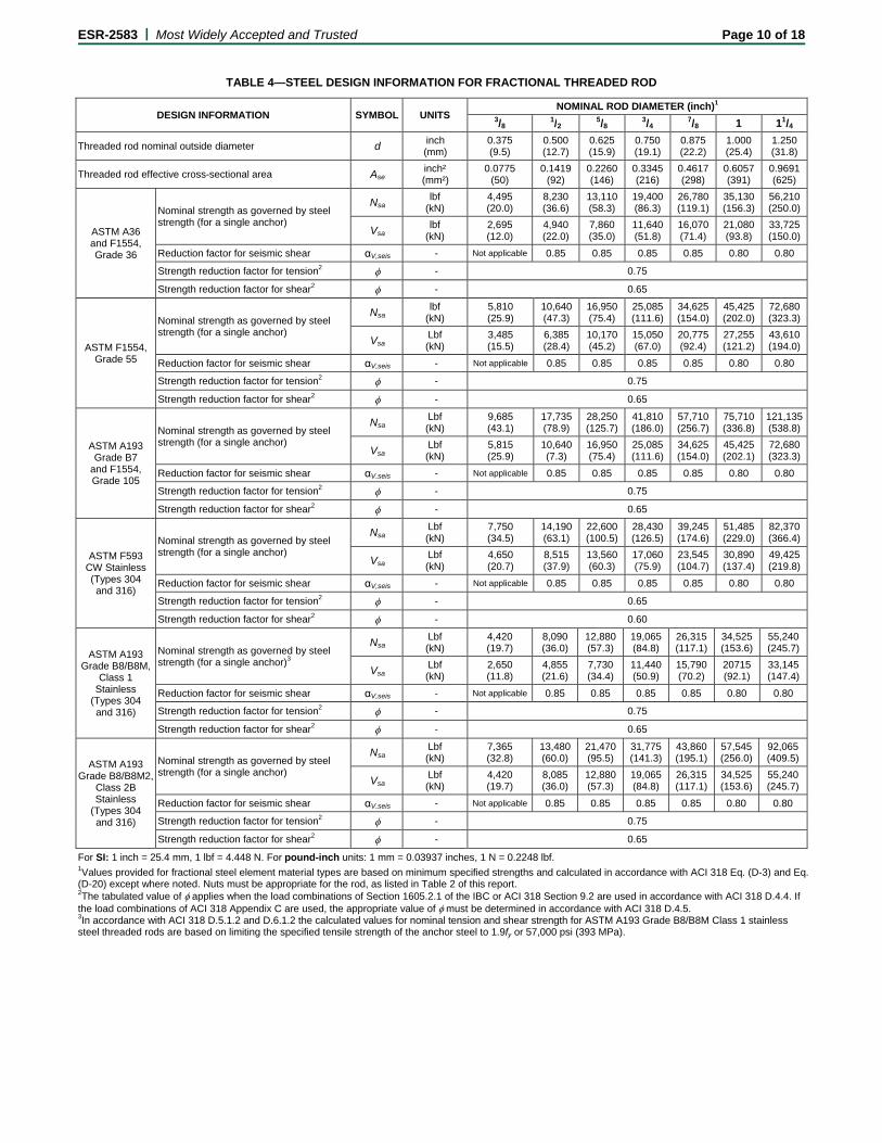
TABLE 4—STEEL DESIGN INFORMATION FOR FRACTIONAL THREADED ROD
For SI: 1 inch = 25.4 mm, 1 lbf = 4.448 N. For pound-inch units: 1 mm = 0.03937 inches, 1 N = 0.2248 lbf.
1Values provided for fractional steel element material types are based on minimum specified strengths and calculated in accordance with ACI 318 Eq. (D-3) and Eq. (D-20) except where noted. Nuts must be appropriate for the rod, as listed in Table 2 of this report. 2The tabulated value of applies when the load combinations of Section 1605.2.1 of the IBC or ACI 318 Section 9.2 are used in accordance with ACI 318 D.4.4. If the load combinations of ACI 318 Appendix C are used, the appropriate value of must be determined in accordance with ACI 318 D.4.5. 3In accordance with ACI 318 D.5.1.2 and D.6.1.2 the calculated values for nominal tension and shear strength for ASTM A193 Grade B8/B8M Class 1 stainless steel threaded rods are based on limiting the specified tensile strength of the anchor steel to 1.9fy or 57,000 psi (393 MPa).
DESIGN INFORMATION SYMBOL UNITS NOMINAL ROD DIAMETER (inch)1
3/81/2
5/83/4
7/8 1 11/4
Threaded rod nominal outside diameter d inch (mm)
0.375 (9.5)
0.500 (12.7)
0.625 (15.9)
0.750 (19.1)
0.875 (22.2)
1.000 (25.4)
1.250 (31.8)
Threaded rod effective cross-sectional area Ase inch² (mm²)
0.0775 (50)
0.1419 (92)
0.2260 (146)
0.3345 (216)
0.4617 (298)
0.6057 (391)
0.9691 (625)
ASTM A36 and F1554, Grade 36
Nominal strength as governed by steel strength (for a single anchor)
Nsa lbf
(kN) 4,495 (20.0)
8,230 (36.6)
13,110 (58.3)
19,400 (86.3)
26,780 (119.1)
35,130 (156.3)
56,210 (250.0)
Vsa lbf
(kN) 2,695 (12.0)
4,940 (22.0)
7,860 (35.0)
11,640 (51.8)
16,070 (71.4)
21,080 (93.8)
33,725 (150.0)
Reduction factor for seismic shear αV,seis - Not applicable 0.85 0.85 0.85 0.85 0.80 0.80
Strength reduction factor for tension2 - 0.75
Strength reduction factor for shear2 - 0.65
ASTM F1554, Grade 55
Nominal strength as governed by steel strength (for a single anchor)
Nsa lbf
(kN) 5,810 (25.9)
10,640 (47.3)
16,950 (75.4)
25,085 (111.6)
34,625 (154.0)
45,425 (202.0)
72,680 (323.3)
Vsa Lbf (kN)
3,485 (15.5)
6,385 (28.4)
10,170 (45.2)
15,050 (67.0)
20,775 (92.4)
27,255 (121.2)
43,610 (194.0)
Reduction factor for seismic shear αV,seis - Not applicable 0.85 0.85 0.85 0.85 0.80 0.80
Strength reduction factor for tension2 - 0.75
Strength reduction factor for shear2 - 0.65
ASTM A193 Grade B7
and F1554, Grade 105
Nominal strength as governed by steel strength (for a single anchor)
NsaLbf (kN)
9,685 (43.1)
17,735 (78.9)
28,250 (125.7)
41,810 (186.0)
57,710 (256.7)
75,710 (336.8)
121,135(538.8)
VsaLbf (kN)
5,815 (25.9)
10,640 (7.3)
16,950 (75.4)
25,085 (111.6)
34,625 (154.0)
45,425 (202.1)
72,680 (323.3)
Reduction factor for seismic shear αV,seis - Not applicable 0.85 0.85 0.85 0.85 0.80 0.80
Strength reduction factor for tension2 - 0.75
Strength reduction factor for shear2 - 0.65
ASTM F593 CW Stainless (Types 304 and 316)
Nominal strength as governed by steel strength (for a single anchor)
Nsa Lbf (kN)
7,750 (34.5)
14,190 (63.1)
22,600 (100.5)
28,430 (126.5)
39,245 (174.6)
51,485 (229.0)
82,370 (366.4)
Vsa Lbf (kN)
4,650 (20.7)
8,515 (37.9)
13,560 (60.3)
17,060 (75.9)
23,545 (104.7)
30,890 (137.4)
49,425 (219.8)
Reduction factor for seismic shear αV,seis - Not applicable 0.85 0.85 0.85 0.85 0.80 0.80
Strength reduction factor for tension2 - 0.65
Strength reduction factor for shear2 - 0.60
ASTM A193 Grade B8/B8M,
Class 1 Stainless
(Types 304 and 316)
Nominal strength as governed by steel strength (for a single anchor)3
NsaLbf (kN)
4,420 (19.7)
8,090 (36.0)
12,880 (57.3)
19,065 (84.8)
26,315 (117.1)
34,525 (153.6)
55,240 (245.7)
VsaLbf (kN)
2,650 (11.8)
4,855 (21.6)
7,730 (34.4)
11,440 (50.9)
15,790 (70.2)
20715 (92.1)
33,145 (147.4)
Reduction factor for seismic shear αV,seis - Not applicable 0.85 0.85 0.85 0.85 0.80 0.80
Strength reduction factor for tension2 - 0.75
Strength reduction factor for shear2 - 0.65
ASTM A193 Grade B8/B8M2,
Class 2B Stainless
(Types 304 and 316)
Nominal strength as governed by steel strength (for a single anchor)
NsaLbf (kN)
7,365 (32.8)
13,480 (60.0)
21,470 (95.5)
31,775 (141.3)
43,860 (195.1)
57,545 (256.0)
92,065 (409.5)
VsaLbf (kN)
4,420 (19.7)
8,085 (36.0)
12,880 (57.3)
19,065 (84.8)
26,315 (117.1)
34,525 (153.6)
55,240 (245.7)
Reduction factor for seismic shear αV,seis - Not applicable 0.85 0.85 0.85 0.85 0.80 0.80
Strength reduction factor for tension2 - 0.75
Strength reduction factor for shear2 - 0.65

ESR-2583 | Most Widely Accepted and Trusted Page 11 of 18
TABLE 5—STEEL DESIGN INFORMATION FOR REINFORCING BARS
DESIGN INFORMATION SYMBOL UNITS NOMINAL REINFORCING BAR SIZE (REBAR)1
No. 3 No. 4 No. 5 No. 6 No. 7 No. 8 No. 9 No. 10
Rebar nominal outside diameter d inch (mm)
0.375 (9.5)
0.500 (12.7)
0.625 (15.9)
0.750 (19.1)
0.875 (22.2)
1.000 (25.4)
1.125 (28.7)
1.250 (32.3)
Rebar effective cross-sectional area Ase inch2 (mm2)
0.110 (71)
0.200 (129)
0.310 (200)
0.440 (284)
0.600 (387)
0.790 (510)
1.000 (645)
1.270 (819)
ASTM A615, Grade
75
Nominal strength as governed by steel strength (for a single anchor)
Nsa lbf
(kN) 11,000 (48.9)
20,000 (89.0)
31,000 (137.9)
44,000 (195.7)
60,000 (266.9)
79,000 (351.4)
100,000(444.8)
127,000(564.9)
Vsa lbf
(kN) 6,600 (29.4)
12,000 (53.4)
18,600 (82.7)
26,400 (117.4)
36,000 (160.1)
47,400 (210.8)
60,000 (266.9)
76,200 (338.9)
Reduction factor for seismic shear αV,seis - Not applicable 0.70 0.70 0.70 0.70 0.70 0.70 0.70
Strength reduction factor for tension2 - 0.65
Strength reduction factor for shear2 - 0.60
ASTM A615, Grade
60
Nominal strength as governed by steel strength (for a single anchor)
Nsa lbf
(kN) 9,900 (44.0)
18,000 (80.1)
27,900 (124.1)
39,600 (176.1)
54,000 (240.2)
71,100 (316.3)
90,000 (400.3)
114,300(508.4)
Vsa lbf
(kN) 5,940 (26.4)
10,800 (48.0)
16,740 (74.5)
23,760 (105.7)
32,400 (144.1)
42,660 (189.8)
54,000 (240.2)
68,580 (305.0)
Reduction factor for seismic shear αV,seis - Not applicable 0.70 0.70 0.70 0.70 0.70 0.70 0.70
Strength reduction factor for tension2 - 0.65
Strength reduction factor for shear2 - 0.60
ASTM A706, Grade
60
Nominal strength as governed by steel strength (for a single anchor)
Nsa lbf
(kN) 8,800 (39.1)
16,000 (71.2)
24,800 (110.3)
35,200 (156.6)
48,000 (213.5)
63,200 (281.1)
80,000 (355.9)
101,600(452.0)
Vsa lbf
(kN) 5,280 (23.5)
9,600 (42.7)
14,880 (66.2)
21,120 (94.0)
28,800 (128.1)
37,920 (168.7)
48,000 (213.5)
60,960 (271.2)
Reduction factor for seismic shear αV,seis - Not applicable 0.70 0.70 0.70 0.70 0.70 0.70 0.70
Strength reduction factor for tension2 - 0.75
Strength reduction factor for shear2 - 0.65
ASTM A615, Grade
40
Nominal strength as governed by steel strength (for a single anchor)
Nsa lbf
(kN) 6,600 (29.4)
12,000 (53.4)
18,600 (82.7)
26,400 (117.4) In accordance with ASTM A615,
Grade 40 bars are furnished only in sizes No. 3 through No. 6
Vsa lbf
(kN) 3,960 (17.6)
7,200 (32.0)
11,160 (49.6)
15,840 (70.5)
Reduction factor for seismic shear αV,seis - Not applicable 0.70 0.70 0.70
Strength reduction factor for tension2 - 0.65
Strength reduction factor for shear2 - 0.60
For SI: 1 inch = 25.4 mm, 1 lbf = 4.448 N. For pound-inch units: 1 mm = 0.03937 inches, 1 N = 0.2248 lbf.
1Values provided for reinforcing bar material types based on minimum specified strengths and calculated in accordance with ACI 318 Eq. (D-3) and Eq. (D-20). 2The tabulated value of applies when the load combinations of Section 1605.2.1 of the IBC or ACI 318 Section 9.2 are used in accordance with ACI 318 D.4.4. If the load combinations of ACI 318 Appendix C are used, the appropriate value of must be determined in accordance with ACI 318 D.4.5.
TABLE 6—CONCRETE BREAKOUT AND PRYOUT DESIGN INFORMATION FOR FRACTIONAL THREADED ROD AND REINFORCING BARS IN HOLES DRILLED WITH A HAMMER DRILL AND CARBIDE BIT OR A CORE DRILL AND DIAMOND CORE BIT1
DESIGN INFORMATION SYMBOL UNITS NOMINAL ROD DIAMETER (inch) / REINFORCING BAR SIZE
3/8 or #3 1/2 or #4 5/8 or #5 3/4 or #6 7/8 or #7 1 or #8 #9 11/4 or #10
Effectiveness factor for cracked concrete kc,cr -
(SI) Not
Applicable 17
(7.1)
Effectiveness factor for uncracked concrete kc,uncr -
(SI) 24
(10.0)
Minimum embedment hef,min inch (mm)
23/8 (60)
23/4 (70)
31/8 (79)
31/2 (89)
31/2 (89)
4 (102)
41/2 (114)
5 (127)
Maximum embedment hef,max inch (mm)
41/2 (114)
10 (254)
121/2 (318)
15 (381)
171/2 (445)
20 (508)
221/2 (572)
25 (635)
Minimum anchor spacing smin inch (mm)
17/8 (48)
21/2 (64)
31/8 (79)
33/4 (95)
43/8 (111)
5 (127)
55/8 (143)
61/4 (159)
Minimum edge distance cmin inch (mm)
5d where d is nominal outside diameter of the anchor; see Section 4.1.9 of this report for design with reduced minimum edge distances
Minimum member thickness hmin inch (mm)
hef + 11/4 (hef + 30)
hef + 2do where do is hole diameter; for installation parameters see Table 9 of this report
Critical edge distance—splitting (for uncracked concrete only) cac
inch (mm)
See Section 4.1.10 of this report
Strength reduction factor for tension, concrete failure modes, Condition B2 - 0.65
Strength reduction factor for shear, concrete failure modes, Condition B2 - 0.70
For SI: 1 inch = 25.4 mm, 1 lbf = 4.448 N. For pound-inch units: 1 mm = 0.03937 inch, 1 N = 0.2248 lbf.
1Additional setting information is described in the installation instructions, Figure 5 of this report. 2Condition A requires supplemental reinforcement, while Condition B applies where supplemental reinforcement is not provided or where pryout governs, as set forth in ACI 318 D.4.4. The tabulated value of applies when the load combinations of Section 1605.2.1 of the IBC or ACI 318 Section 9.2 are used in accordance with ACI 318 D.4.4. If the load combinations of ACI 318 Appendix C are used, the appropriate value of must be determined in accordance with ACI 318 D.4.5.

ESR-2583 | Most Widely Accepted and Trusted Page 12 of 18
TABLE 7—BOND STRENGTH DESIGN INFORMATION FOR FRACTIONAL THREADED RODS AND REINFORCING BARS IN HOLES DRILLED WITH A HAMMER DRILL AND CARBIDE BIT1
DESIGN INFORMATION SYMBOL UNITS NOMINAL ROD DIAMETER (inch) / REINFORCING BAR SIZE
3/8 or #3 1/2 or #4 5/8 or #5 3/4 or #6 7/8 or #7 1 or #8 #9 11/4 or #10
Minimum embedment hef,min inch (mm)
23/8 (60)
23/4 (70)
31/8 (79)
31/2 (89)
31/2 (89)
4 (102)
41/2 (114)
5 (127)
Maximum embedment
Dry concrete and saturated concrete7 hef,max
inch (mm)
41/2 (114)
10 (254)
121/2 (318)
15 (381)
171/2 (445)
20 (508)
221/2 (572)
25 (635)
Water-filled hole (flooded) hef,max inch (mm)
41/2 (114)
6 (152)
71/2 (190)
9 (225)
101/2 (267)
12 (305)
131/2 (343)
15 (381)
Temperature Range A2,4,5
Characteristic bond strength in cracked concrete8 k,cr
psi (N/mm2)
Not applicable
1,119 (7.7)
920 (6.3)
857 (5.9)
807 (5.6)
807 (5.6)
807 (5.6)
807 (5.6)
Characteristic bond strength in uncracked concrete9 k,uncr
psi (N/mm2)
2,375(16.4)
2,244 (15.5)
2,148 (14.8)
2,073 (14.3)
2,013 (13.9)
1,960 (13.5)
1,916 (13.2)
1,876 (12.9)
Temperature Range B3,4,5
Characteristic bond strength in cracked concrete8 k,cr
psi (N/mm2)
Not applicable
547 (3.8)
450 (3.1)
419 (2.9)
394 (2.7)
394 (2.7)
394 (2.7)
394 (2.7)
Characteristic bond strength in uncracked concrete9 k,uncr
psi (N/mm2)
1,160(7.9)
1,097 (7.6)
1,050 (7.2)
1,013 (7.0)
984 (6.8)
958 (6.6)
936 (6.5)
917 (6.3)
Permissible installation conditions6
Dry concrete d - 0.65 0.65 0.65 0.65 0.65 0.65 0.65 0.65
Water-saturated concrete ws - 0.45 0.45 0.45 0.45 0.45 0.45 0.45 0.45
ws - 0.93 0.90 0.96 1.0 1.0 1.0 1.0 0.99
Water-filled hole (flooded) wf - 0.45 0.45 0.45 0.45 0.45 0.45 0.45 0.45
wf - 0.93 0.83 0.75 0.70 0.65 0.62 0.59 0.56
For SI: 1 inch = 25.4 mm, 1 psi = 0.006894 MPa. For pound-inch units: 1 mm = 0.03937 inch, 1 MPa = 145.0 psi.
1Bond strength values correspond to concrete compressive strength f'c = 2,500 psi. For concrete compressive strength, f'c between 2,500 psi and 8,000 psi, the tabulated characteristic bond strength may be increased by a factor of (f'c / 2,500)0.12 [For SI: (f'c / 17.2)0.12]. See Section 4.1.5 of this report. 2Temperature Range A: Maximum long-term service temperature = 75°F (24°C), maximum short-term service temperature = 104°F (40°C). 3Temperature Range B: Maximum long-term service temperature = 110°F (43°C), maximum short-term service temperature = 140°F (60°C). The maximum short-term service temperature may be increased to 162°F (72°C) for Temperature Range B provided characteristic bond strengths are reduced by 10 percent. 4Short-term elevated concrete temperatures are those that occur over brief intervals, e.g. as a result of diurnal cycling. Long-term concrete temperatures are roughly constant over significant periods of time. 5Characteristic bond strengths are for sustained loads including dead and live loads. For load combinations consisting of short-term loads only such as wind or seismic, bond strengths may be increased 70 percent for Temperature Range B. 6Permissible installation conditions include dry concrete, water-saturated concrete and water-filled holes. Water-filled holes include applications in dry or water-saturated concrete where the drilled holes contain standing water at the time of anchor installation. For installation instructions see Figure 5 of this report. 7Maximum embedment is limited to twelve anchor diameters for horizontal and upwardly inclined installations. 8For structures assigned to Seismic Design Categories C, D, E or F, bond strength values for cracked concrete do not require an additional reduction factor applied (αN,seis = 1.0). See Section 4.1.11 of this report. 9Bond strength values for uncracked concrete are applicable for structures assigned to Seismic Design Categories A and B only.
TABLE 8—BOND STRENGTH DESIGN INFORMATION FOR FRACTIONAL THREADED RODS AND REINFORCING BARS IN HOLES DRILLED WITH A CORE DRILL AND DIAMOND CORE BIT1
DESIGN INFORMATION SYMBOL UNITS NOMINAL ROD DIAMETER (inch) / REINFORCING BAR SIZE
1/2 or #4 5/8 or #5 3/4 or #6 7/8 or #7 1 or #8
Minimum embedment hef,min inch (mm)
23/4 (70)
31/8 (79)
31/2 (89)
31/2 (89)
4 (102)
Maximum embedment7 hef,max inch (mm)
10 (254)
121/2 (318)
15 (381)
171/2 (445)
20 (508)
Temperature Range A2,4,5
Characteristic bond strength in uncracked concrete8 k,uncr
psi (N/mm2)
1,419 (9.8)
1,351 (9.3)
1,298 (9.0)
1,257 (8.7)
1,221 (8.4)
Temperature Range B3,4,5
Characteristic bond strength in uncracked concrete8 k,uncr
psi (N/mm2)
1,074 (7.4)
1,023 (7.1)
983 (6.8)
951 (6.6)
924 (6.4)
Permissible Installation Conditions6
Dry concrete d - 0.65 0.65 0.65 0.65 0.65
Water-saturated concrete ws - 0.55 0.45 0.45 0.45 0.45
ws - 1.0 1.0 1.0 1.0 1.0
Water-filled hole (flooded) wf - 0.45 0.45 0.45 0.45 0.45
wf - 0.94 0.95 0.95 0.95 0.96
For SI: 1 inch = 25.4 mm, 1 psi = 0.006894 MPa. For pound-inch units: 1 mm = 0.03937 inch, 1 MPa = 145.0 psi.
1Bond strength values correspond to concrete compressive strength f'c = 2,500 psi. For concrete compressive strength, f'c between 2,500 psi and 8,000 psi, the tabulated characteristic bond strength may be increased by a factor of (f'c / 2,500)0.12 [For SI: (f'c / 17.2)0.12]. See Section 4.1.5 of this report. 2Temperature Range A: Maximum short-term service temperature = 104°F (40°C), maximum long-term service temperature = 75°F (24°C). 3Temperature Range B: Maximum short-term service temperature = 140°F (60°C), maximum long-term service temperature = 110°F (43°C). The maximum short-term service temperature may be increased to 162°F (72°C) for Temperature Range B provided characteristic bond strengths are reduced by 10 percent. 4Short-term elevated concrete temperatures are those that occur over brief intervals, e.g. as a result of diurnal cycling. Long-term concrete temperatures are roughly constant over significant periods of time. 5Characteristic bond strengths are for sustained loads including dead and live loads. For load combinations consisting of short-term loads only such as wind or seismic, bond strengths may be increased by 50 percent for Temperature Range A and 65 percent for Temperature Range B. 6Permissible installation conditions include dry concrete, water-saturated concrete and water-filled holes. Water-filled holes include applications in dry or water-saturated concrete where the drilled holes contain standing water at the time of anchor installation. For installation instructions see Figure 5 of this report. 7Maximum embedment for dry concrete and saturated concrete is limited to twelve anchor diameters for horizontal and upwardly inclined installations. 8Bond strength values for uncracked concrete are applicable for structures assigned to Seismic Design Categories A and B only.

E
ESR-2583 | M
TA
FIGU
Most Widely Acc
FIG
ABLE 9—INSTAL
URE 3—PE1000+
cepted and Tru
GURE 2—BOND
LLATION PARA
PARAMET
Threaded rod outside diame
Rebar nominaoutside diame
Carbide drill bnominal size
Diamond corenominal size
Minimum embedment
Maximum embedment2
Max. torque
Max. torque3 (A36/Grade 36
Max. torque4 (Class 1 SS ro
Minimum anchspacing
Minimum edgedistance
Minimum memthickness
For SI: 1 inchlbf.
1N/A = Not Ap2The maximumwater-filled (flo3These values4These values
+ EPOXY ADHE
usted
D STRENGTHS
AMETERS FOR F
ER SYMBOL UN
eter d
in(m
al eter d
in(m
bit do (dbit) in
e bit do (dbit) in
hef,min in(m
hef,max in(m
Tmax ft
6 rod) Tmax ft
od) Tmax ft
hor smin
in(m
e cmin
in(m
mber hmin
in(m
h = 25.4 mm, 1 ft-l
plicable.
m embedment is limooded) holes drilleds apply to ASTM A3s apply to ASTM A1
ESIVE ANCHOR
BASED ON NOM
FRACTIONAL T
NITSNOM
3/8 or #3 1/2
nch mm)
0.375 (9.5)
0(1
nch mm)
0.375 (9.5)
0(1
nch 7/16
nch N/A1
nch mm)
23/8 (60) (
nch mm)
41/2 (114) (2
t-lbs 15
t-lbs 10
t-lbs 5
nch mm)
17/8 (48) (
nch mm)
5d;or see S
nch mm)
hef + 11/(hef + 30
lbf = 1.356 N-m. F
mited to 12d for hord with a carbide dri36 / F1554 Grade 3193 Grade B8/B8M
SYSTEM INCLU
MINAL ANCHOR
THREADED ROD
MINAL ROD DIAM
or #4 5/8 or #5
0.500 12.7)
0.625 (15.9)
0.500 12.7)
0.625 (15.9)
9/16 11/16 or 3/4
5/8 3/4
23/4 (70)
31/8 (79)
10 254)
121/2 (318)
33 60
25 50
20 40
21/2 (64)
31/8 (79)
Section 4.1.9 of thimin
/4 0)
For pound-inch u
rizontal and upwardll bit.
36 carbon steel threM (Class 1) stainless
UDING TYPICAL
R DIAMETER
D AND REINFOR
ETER (inch) / REI3/4 or #6 7/8 or #
0.750 (19.1)
0.875 (22.2)
0.750 (19.1)
0.875 (22.2)
7/8 1
7/8 1
31/2 (89)
31/2 (89)
15 (381)
171/2 (445)
105 125
90 125
60 100
33/4 (95)
43/8 (111)
s report for installanimum edge distan
hef
units: 1 mm = 0.03
dly inclined installa
eaded rods only. s steel threaded ro
L STEEL ANCH
Pag
RCING BARS
NFORCING BAR S
7 1 or #8 #9
1.000 (25.4)
N/A1
1.000 (25.4)
1.125(28.7)
11/8 13/8
11/4 N/A1
4 (102)
41/2 (114)
20 (508)
221/2(572)
165 200
165 N/A1
165 N/A1
5 (127)
55/8 (143)
ation parameters wices
+ 2do
3937 inch, 1 N-m
tions and for instal
ods only.
OR ELEMENTS
ge 13 of 18
SIZE
11/4 #10
1.250(31.8)
N/A1
N/A1 1.250(31.8)
13/8 11/2
N/A1 N/A1
5 (127)
5 (127)
25 (635)
25 (635)
280 280
280 N/A1
280 N/A1
61/4 (159)
61/4 (159)
ith reduced
= 0.7375 ft-
lations in
S
E ESR-2583 | MMost Widely Acccepted and Tru
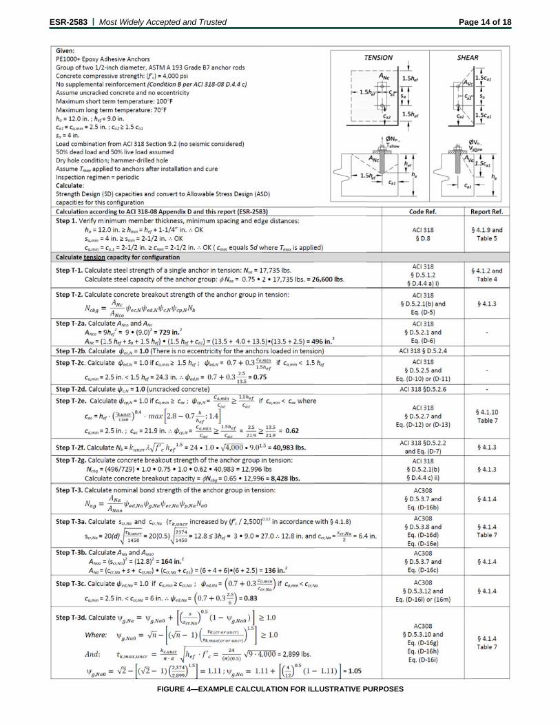
FIGURE 4—EXA
usted
AMPLE CALCUL
LATION FOR ILLLUSTRATIVE PPURPOSES
Pagge 14 of 18
E
ESR-2583 | MMost Widely Acc
FIGUR
cepted and Tru
RE 4—EXAMPLE
usted
E CALCULATIO
N FOR ILLUSTRRATIVE PURPOOSES (Continued
Pag
d)
ge 15 of 18
ESR-2583 | Most Widely Accepted and Trusted Page 16 of 18
TABLE 10—EXAMPLE OF PE1000+ EPOXY ADHESIVE ANCHOR ALLOWABLE STRESS DESIGN (ASD) VALUES FOR ILLUSTRATIVE PURPOSES1,2,3,4,6,9,10,13,14,16
NOMINAL ANCHOR
ROD DIAMETER OR REBAR
SIZE d
(inch) / (No.)
EFFECTIVE EMBED.5
hef (inches)
CONCRETE STRENGTH12
f'c (psi)
EFFECTIVE-NESS
FACTOR FOR
UNCRACKED CONCRETE
kuncr
CHARACTERISTICBOND
STRENGTH
k,uncr (psi)
NOMINAL STRENGTH IN
TENSION Nn
(pounds)
STRENGTH REDUCTON
FACTOR 15
ALLOWABLE TENSION LOAD11
Nn / (pounds)
Temp. Range A7
Temp. Range B8
Temp. Range A7
Temp. Range B8
Temp. Range A7
Temp. Range B8
Temp. Range A7
Temp. Range B8
ASTM A193 Grade B7 Threaded Rod
3/8 23/8 2,500 24 2,375 1,160 4,392 3,246 0.65 (conc) 0.65 (bond) 1,930 1,425
41/2 2,500 24 2,375 1,160 9,750 6,150 0.75 (steel) 0.65 (bond) 4,945 2,700
1/2 23/4 2,500 24 2,244 1,097 5,472 4,713 0.65 (conc) 0.65 (bond) 2,400 2,070
10 2,500 24 2,244 1,097 17,750 17,232 0.75 (steel) 0.65 (bond) 8,995 7,570
5/8 31/8 2,500 24 2,148 1,050 6,629 6,375 0.65 (conc) 0.65 (bond) 2,910 2,800
121/2 2,500 24 2,148 1,050 28,250 25,771 0.75 (steel) 0.65 (bond) 14,320 11,320
3/4 31/2 2,500 24 2,073 1,013 7,857 7,857 0.65 (conc) 0.65 (conc) 3,450 3,450
15 2,500 24 2,073 1,013 41,875 35,802 0.75 (steel) 0.65 (bond) 21,220 15,725
7/8 31/2 2,500 24 2,013 984 7,857 7,857 0.65 (conc) 0.65 (conc) 3,450 3,450
171/2 2,500 24 2,013 984 57,750 47,336 0.75 (steel) 0.65 (bond) 29,265 20,790
1 4 2,500 24 1,960 958 9,600 9,600 0.65 (conc) 0.65 (conc) 4,215 4,215
20 2,500 24 1,960 958 75,750 60,193 0.75 (steel) 0.65 (bond) 38,390 26,435
11/4 5 2,500 24 1,876 917 13,416 13,416 0.65 (conc) 0.65 (conc) 5,890 5,890
25 2,500 24 1,876 917 121,125 90,026 0.75 (steel) 0.65 (bond) 61,380 39,535
ASTM A706 Grade 60 Reinforcing Bar
3 23/8 2,500 24 2,375 1,160 4,392 3,246 0.65 (conc) 0.65 (bond) 1,930 1,425
41/2 2,500 24 2,375 1,160 8,800 6,150 0.75 (steel) 0.65 (bond) 4,460 2,700
4 23/4 2,500 24 2,244 1,097 5,472 4,713 0.65 (conc) 0.65 (bond) 2,400 2,070
10 2,500 24 2,244 1,097 16,000 17,232 0.75 (steel) 0.65 (bond) 8,110 7,570
5 31/8 2,500 24 2,148 1,050 6,629 6,375 0.65 (conc) 0.65 (bond) 2,910 2,800
121/2 2,500 24 2,148 1,050 24,800 25,771 0.75 (steel) 0.65 (bond) 12,570 11,320
6 31/2 2,500 24 2,073 1,013 7,857 7,857 0.65 (conc) 0.65 (conc) 3,450 3,450
15 2,500 24 2,073 1,013 35,200 35,802 0.75 (steel) 0.65 (bond) 17,840 15,725
7 31/2 2,500 24 2,013 984 7,857 7,857 0.65 (conc) 0.65 (conc) 3,450 3,450
171/2 2,500 24 2,013 984 48,000 47,336 0.75 (steel) 0.65 (bond) 24,325 20,790
8 4 2,500 24 1,960 958 9,600 9,600 0.65 (conc) 0.65 (conc) 4,215 4,215
20 2,500 24 1,960 958 63,200 60,193 0.75 (steel) 0.65 (bond) 32,025 26,435
9 41/2 2,500 24 1,916 936 11,455 11,455 0.65 (conc) 0.65 (conc) 5,030 5,030
221/2 2,500 24 1,916 936 80,000 74,432 0.75 (steel) 0.65 (bond) 40,540 32,690
10 5 2,500 24 1,876 917 13,416 13,416 0.65 (conc) 0.65 (conc) 5,890 5,890
25 2,500 24 1,876 917 101,600 90,026 0.75 (steel) 0.65 (bond) 51,485 39,535
For SI: 1 inch = 25.4 mm, 1 lbf = 4.448 N, 1 psi = 0.006894 MPa. For pound-inch units: 1 mm = 0.03937 inch, 1 N = 0.2248 lbf, 1 MPa = 145.0 psi.
1Single anchor with static tension load only; ASTM A193 Grade B7 threaded rod and ASTM A706 Grade 60 reinforcing bar. 2Vertical downward installation direction. 3Special inspection interval = Periodic. 4Installation temperature = 41°F (5°C) to 104°F (40°C) for base material; 41°F (5°C) to 95°F (35°C) for cartridge adhesive. 5Embedment = hef,min and hef,max for each diameter. 6Concrete determined to remain uncracked for the life of the anchorage. 7Temperature Range A: Long-term service temperature = 75°F (24°C), short-term service temperature = 104°F (40°C). 8Temperature Range B: Long-term service temperature = 110°F (43°C), short-term service temperature = 140°F (60°C). 9Load combinations are based on ACI 318 Section 9.2 with no seismic loading considered. 10Thirty percent (30%) dead load and seventy percent (70%) live load; controlling load combination 1.2D + 1.6L. 11Calculation of weighted average for the conversion factor, = 1.2(0.3) + 1.6(0.7) = 1.48. 12f’c = 2,500 psi compressive strength (normal-weight concrete). 13ca1 = ca2 cac.
14h hmin. 15Strength reduction factor from controlling nominal strength in tension [i.e. steel, concrete (conc), bond] decisive from design assumptions. 16Hammer-drilled holes in dry concrete.
E ESR-2583 | MMost Widely Acc
FIGUR
cepted and Tru
RE 5—MANUFAC
usted
CTURER’S PUB
BLISHED INSTAALLATION INSTRRUCTIONS (MP
Pag
II)
ge 17 of 18
E ESR-2583 | MMost Widely Acc
FIGURE 5—M
cepted and Tru
MANUFACTURE
usted
ER’S PUBLISHE
ED INSTALLATIOON INSTRUCTIOONS (MPII) (Con
Pag
ntinued)
ge 18 of 18

ICC-ES Evaluation Reports are not to be construed as representing aesthetics or any other attributes not specifically addressed, nor are they to be construed as an endorsement of the subject of the report or a recommendation for its use. There is no warranty by ICC Evaluation Service, LLC, express or implied, as to any finding or other matter in this report, or as to any product covered by the report.
Copyright © 2013 Page 1 of 1 1000
ICC-ES Evaluation Report ESR-2583 FBC Supplement Issued May 1, 2013 This report is subject to renewal December 1, 2013.
www.icc-es.org | (800) 423-6587 | (562) 699-0543 A Subsidiary of the International Code Council ®
DIVISION: 03 00 00—CONCRETE Section: 03 16 00—Concrete Anchors
DIVISION: 05 00 00—METALS Section: 05 05 19—Post-Installed Concrete Anchors
REPORT HOLDER:
POWERS FASTENERS, INC. 2 POWERS LANE BREWSTER, NEW YORK 10509 (914) 235-6300 or (800) 524-3244 www.powers.com [email protected]
EVALUATION SUBJECT:
POWERS PE1000+® EPOXY ADHESIVE ANCHOR SYSTEM IN CRACKED AND UNCRACKED CONCRETE
1.0 REPORT PURPOSE AND SCOPE
Purpose:
The purpose of this evaluation report supplement is to indicate that the Powers PE1000+® Epoxy Adhesive Anchor System in Cracked and Uncracked Concrete, recognized in ICC-ES master evaluation report ESR-2583, has also been evaluated for compliance with the codes noted below.
Applicable code editions:
2010 Florida Building Code—Building
2010 Florida Building Code—Residential
2.0 CONCLUSIONS
The Powers PE1000+® Epoxy Adhesive Anchor System in Cracked and Uncracked Concrete, described in Sections 2.0 through 7.0 of the master evaluation report ESR-2583, complies with the 2010 Florida Building Code—Building and the 2010 Florida Building Code—Residential, provided the design and installation are in accordance with the International Building Code® (IBC) provisions noted in the master report, and under the following conditions:
Design wind loads must be based on Section 1609 of the 2010 Florida Building Code—Building or Section 301.2.1.1 of the 2010 Florida Building Code—Residential, as applicable.
Load combinations must be in accordance with Section 1605.2 or Section 1605.3 of the 2010 Florida Building Code—Building, as applicable.
The modifications to ACI 318 as shown in 2009 IBC Sections 1908.1.9 and 1908.1.10, as noted in 2009 IBC Section 1912.1, do not apply to the 2010 Florida Building Code.
Use of the Powers PE1000+® epoxy adhesive anchors with stainless steel threaded rod materials and reinforcing bars has also been found to be in compliance with the High-Velocity Hurricane Zone provisions of the 2010 Florida Building Code—Building and the 2010 Florida Building Code—Residential, when the following conditions are met:
Design wind loads for use of the anchors in a High-Velocity Hurricane Zone must be based on Section 1620 of the Florida Building Code—Building.
Reinforcing bars must be in accordance with Section 1922.4 of the Florida Building Code—Building.
Use of the Powers PE1000+® epoxy adhesive anchors with carbon steel threaded rod materials for compliance with the High-Velocity Hurricane Zone provisions of the 2010 Florida Building Code—Building and the 2010 Florida Building Code—Residential has not been evaluated, and is outside the scope of this supplemental report.
For products falling under Florida Rule 9N-3, verification that the report holder’s quality assurance program is audited by a quality assurance entity approved by the Florida Building Commission for the type of inspections being conducted is the responsibility of an approved validation entity (or the code official when the report holder does not possess an approval by the Commission).
This supplement expires concurrently with the master report reissued December 1, 2011, revised May 2013.