icam ift-p product guide · icamift-pproductguide icambyxtralis ii documentconventions...
TRANSCRIPT

ICAM IFT-PProduct Guide
May 2011Document: 19317Revision: ABuild: 0Part Number: 29714


ICAM by Xtralis ICAM IFT-P Product Guide
www.xtralis.com i
Intellectual Property and CopyrightThis document includes registered and unregistered trademarks. All trademarks displayed are the trademarks oftheir respective owners. Your use of this document does not constitute or create a licence or any other right to usethe name and/or trademark and/or label.
This document is subject to copyright owned by Xtralis AG (“Xtralis”). You agree not to copy, communicate to thepublic, adapt, distribute, transfer, sell, modify or publish any contents of this document without the express priorwritten consent of Xtralis.
DisclaimerThe contents of this document is provided on an “as is” basis. No representation or warranty (either express orimplied) is made as to the completeness, accuracy or reliability of the contents of this document. The manufacturerreserves the right to change designs or specifications without obligation and without further notice. Except asotherwise provided, all warranties, express or implied, including without limitation any implied warranties ofmerchantability and fitness for a particular purpose are expressly excluded.
General WarningThis product must only be installed, configured and used strictly in accordance with the General Terms andConditions, User Manual and product documents available from Xtralis. All proper health and safety precautionsmust be taken during the installation, commissioning and maintenance of the product. The system should not beconnected to a power source until all the components have been installed. Proper safety precautions must be takenduring tests and maintenance of the products when these are still connected to the power source. Failure to do soor tampering with the electronics inside the products can result in an electric shock causing injury or death and maycause equipment damage. Xtralis is not responsible and cannot be held accountable for any liability that may arisedue to improper use of the equipment and/or failure to take proper precautions. Only persons trained through anXtralis accredited training course can install, test and maintain the system.
LiabilityYou agree to install, configure and use the products strictly in accordance with the User Manual and productdocuments available from Xtralis.
Xtralis is not liable to you or any other person for incidental, indirect, or consequential loss, expense or damages ofany kind including without limitation, loss of business, loss of profits or loss of data arising out of your use of theproducts. Without limiting this general disclaimer the following specific warnings and disclaimers also apply:
Fitness for PurposeYou agree that you have been provided with a reasonable opportunity to appraise the products and have madeyour own independent assessment of the fitness or suitability of the products for your purpose. You acknowledgethat you have not relied on any oral or written information, representation or advice given by or on behalf of Xtralisor its representatives.
Total LiabilityTo the fullest extent permitted by law that any limitation or exclusion cannot apply, the total liability of Xtralis inrelation to the products is limited to:
i. in the case of services, the cost of having the services supplied again; orii. in the case of goods, the lowest cost of replacing the goods, acquiring equivalent goods or having the goods
repaired.
IndemnificationYou agree to fully indemnify and hold Xtralis harmless for any claim, cost, demand or damage (including legal costson a full indemnity basis) incurred or which may be incurred arising from your use of the products.
MiscellaneousIf any provision outlined above is found to be invalid or unenforceable by a court of law, such invalidity orunenforceability will not affect the remainder which will continue in full force and effect. All rights not expresslygranted are reserved.
ICAM IFT-P Product Guide ICAM by Xtralis
ii www.xtralis.com
Document ConventionsThe following typographic conventions are used in this document:
Convention Description
Bold Used to denote: emphasisUsed for names of menus, menu options, toolbar buttons
Italics Used to denote: references to other parts of this document or otherdocuments. Used for the result of an action.
The following icons are used in this document:
Convention Description
Caution: This icon is used to indicate that there is a danger toequipment. The danger could be loss of data, physical damage, orpermanent corruption of configuration details.
Warning: This icon is used to indicate that there is a danger of electricshock. This may lead to death or permanent injury.
Warning: This icon is used to indicate that there is a danger ofhazardous laser radiation exposure.
Warning: This icon is used to indicate that there is a danger ofinhaling dangerous substances. This may lead to death or permanentinjury.
Contact UsThe Americas +1 781 740 2223
Asia +852 2916 8894
Australia and New Zealand +61 3 9936 7000
Europe, Middle East & Africa +44 1442 242 330
www.xtralis.com

ICAM by Xtralis ICAM IFT-P Product Guide
www.xtralis.com iii
Codes and Standards Information for Air Sampling Smoke DetectionWe strongly recommend that this document is read in conjunction with the appropriate local codes and standardsfor smoke detection and electrical connections. This document contains generic product information and somesections may not comply with all local codes and standards. In these cases, the local codes and standards musttake precedence. The information below was correct at time of printing but may now be out of date, check with yourlocal codes, standards and listings for the current restrictions.
FDAThis ICAM product incorporates a 658 nm laser device with an average power less than 10 mW, and is classified asa Class 1 laser product that complies with FDA regulations 21 CFR 1040 with deviations pursuant to Laser Notice50, and with IEC / EN 60825-1. Access to the laser chamber is on the underside of equipment and is restricted bycover. The cover may only be removed by qualified personnel. The laser emits visible light and can be hazardous ifviewed with the naked eye.
CAUTION - Use of controls or adjustments of performance or procedures other than those specified herein mayresult in hazardous radiation exposure.
Laser Chamber SafetyIFT-P detector laser chambers incorporate a 658 nm laser with an average power less than 10mW and are locatedon the underside of the detector when mounted upright on a wall. The laser chamber is identified by two safetylabels shown in the following diagrams.
Figure 2-1: Laser Chamber Safety Labels
Warning: The laser emits visible light and can be hazardous if viewed with the naked eye. Under nocircumstances should the detector chamber be opened except by qualified personnel.

ICAM IFT-P Product Guide ICAM by Xtralis
iv www.xtralis.com
Regional Regulatory Requirements and NoticesULFor open area protection the Fire 1 alarm threshold (signal) must be set within the limits specified by the followingconditions:
l IFT-P detectors must have a Fire 1 threshold set within 0.04 to 0.29% obs/ft
Through validation testing Underwriters Laboratories Inc. has verified that ICAM ECO gas detectors, when installedwithin the sample pipe network, present no significant effects on the smoke detection performance of ICAM. Theuse of the Xtralis ASPIRE2 calculation software is required to verify system design performance with all devicesincluded in the design.
ULCRefer to Appendix C for information on ULC wiring requirements.
UL / ULCl Special applications sensitivity range is 0.001 %/m – 1.6 %/m (0.0003 %/ft to 0.50 %/ft). (For Special
Application it is required obtain approval from the Local Authority Having Jurisdiction.)l Open Area applications sensitivity range is (1.6 %/m – 12.0 %/m) or 0.5 %/ft to 4 %/ft
EN54-20The product must use a power supply conforming to EN54-4.
The product is compliant with EN54-20 sensitivity requirements provided that the hole sensitivity is better andtransport time is less than the following values:
Class A 0.6%obs/m, 60 secs
Class B 1.6%obs/m, 60 secs
Class C 3.6%obs/m, 60 secs
The product is compliant with EN54-20 flow monitoring requirements provided that the following conditions are met:
l Flow Low and Flow High parameters should be set to 85% and 115% respectively for IFT-P detectors.
Additional InformationClass A, B and C detectors passed EN54-20 approvals testing with the following number of holes and detectorsensitivities:
Class A 12 holes, 0.04%obs/m
Class B 36 holes, 0.04%obs/m
Class C 36 holes, 0.1%obs/m
Listings / Approvalsl FMl ULl ULCl VdSl CFEl CE - EMC, LVD and CPDl EN54-20

ICAM by Xtralis ICAM IFT-P Product Guide
www.xtralis.com 1
Table of Contents1 Description and Operation 3
1.1 Introduction 31.2 Principle of Operation 31.3 Flow Monitoring 41.4 Alarms 41.5 Detector Display Panel 51.6 Communications Interface 5
2 Installation and Configuration 72.1 Mounting the Detectors 72.2 Cable Connections 82.3 Connection of Air Sampling Network 132.4 Starting Up 142.5 Configuration 14
3 Maintenance 153.1 Inspection 153.2 Servicing 15
4 Specifications 174.1 Power 174.2 Case 174.3 Operating Conditions 174.4 Sampling Network 174.5 Interfaces 174.6 Alarm 184.7 Communication 18
A Input-Output Modules 19A.1 4-Channel Relay Module 19A.2 8-Channel, 4 - 20mA Output Module 20
B Detector Wiring Diagram Examples 23C UL/ULC Wiring Requirements 25D Remote Display Unit 27
D.1 Installation and Configuration 27D.2 Remote Display Unit Navigation 31D.3 Remote Display Unit Button Functions 32

ICAM IFT-P Product Guide ICAM by Xtralis
2 www.xtralis.com
This page is intentionally left blank.

ICAM by Xtralis ICAM IFT-P Product Guide
www.xtralis.com 3
1 Description and Operation1.1 IntroductionWelcome to the ICAM IFT-P Product Guide. This document is written to provide you with information ontechnical specifications, cabling, and how to install, configure and operate the IFT-P detector.The IFT-P detector is an aspirating smoke detector that provides early warning of fire by analyzing air drawnthrough an air sampling pipe network. A highly sensitive detector chamber is able to detect smoke at very lowconcentrations.
Figure 1-1: IFT-P
1.2 Principle of OperationAir samples are drawn through the pipe network from the protected area through wide bore pipe systems.Wide bore tubes generally have sampling holes drilled at intervals within the protected area.The aspirator draws air from the pipe network into the detector inlets where the samples are combined,filtered, and directed to the laser detection chamber. The IFT-P uses a T-piece of pipe to combine air sampledfrom two inlet pipes.The IFT-P has flow monitoring on both pipes.The detection chamber consists of a laser beam directed acrossan optical chamber, through which the air sample flows. A photodetector built into the optical chambermeasures the amount of light scattering from particles in the air. A clean air sample will cause very littlescattering but as the smoke density of the sample increases, the amount of light directed onto thephotodetector will also increase. The light signal is processed to become a direct measurement of the amountof light scatter caused by smoke. Information about the laser chamber safety can be found in Laser ChamberSafety on page iii.If the smoke detected is higher than the preset alarm thresholds in the detector (Alert, Action, Fire 1 and Fire2), an alarm will be reported. One or more Alarm relays, preset to activate at an alarm threshold will signal thehost panel after a preset time delay. The time delays can be changed as required. Alarm states are alsoshown on the display panel.

ICAM IFT-P Product Guide ICAM by Xtralis
4 www.xtralis.com
1.3 Flow MonitoringThe control systemmonitors for blockages or disconnection of the pipe network by detecting when the air flowis above or below acceptable flow thresholds. Flow thresholds are dependent on air flows measured duringnormalization.The normalization process enables the detector to learn typical air flow characteristics of the system and setsthese expected flow readings to 100%. A normalization sequencemust be performed at installation. Thedetector has default high and low limits and associated delay times, whichmay be changed in the Configuremenu.Detailed information on how to design and install an effective pipe network can be found in ICAM PipeNetwork Design Guide and ICAM Pipe Network Installation Guide.
1.4 AlarmsThe default settings of the four alarm states (Alert, Action, Fire1 and Fire2) are shown in the following table.
Table 1-1: Default Behavior of Alarm States
Level Latched /Unlatched
ThresholdClass A/B/C
Delay
Alert Latched 0.04% obs/m (0.012% obs/ft) 3 secs
Action Latched 0.06% obs/m (0.018% obs/ft) 3 secs
Fire1 Latched 0.08% obs/m (0.024% obs/ft) 3 secs
Fire2 Latched 0.1% obs/m (0.03% obs/ft) 3 secs
If any alarms are unlatched, all resultant actions (relay contacts and display panel indicators) will clear if andwhen the triggering event ceases. If it is latched, all the warningmechanisms aremaintained until action istaken by the user. These alarm states are global and will be set depending on the smoke density beingmeasured, regardless of which sector is being sampled.

ICAM by Xtralis ICAM IFT-P Product Guide
www.xtralis.com 5
1.5 Detector Display PanelThe display panel has LEDs to indicate the Action and Fire 1 alarm states, OK / Fault conditions and powerstatus.
Figure 1-2: Display PanelThe following table describes the display panel LEDs.
Table 1-2: LED Descriptions
LED DescriptionThis Red LED is activated when the Fire 2 alarm threshold is exceeded.
This Red LED is activated when the Fire 1 alarm threshold is exceeded.
This Red LED is activated when the Action alarm threshold is exceeded.
This Red LED is activated when the Alert alarm threshold is exceeded.
This bi-color LED is Green when there is no fault, and Yellow when fault condition isdetected.
Power LED This Blue LED is activated when POWER is supplied to the detector.
1.6 Communications InterfaceIFT-P detectors can connect to a PC with Xtralis VSC or VSM4 software via Ethernet, through a RS232 directserial connection or with RS485 via a RS485/RS232 converter. More details may be found in the ICAMCommunications Guide.

ICAM IFT-P Product Guide ICAM by Xtralis
6 www.xtralis.com
This page is intentionally left blank.

ICAM by Xtralis ICAM IFT-P Product Guide
www.xtralis.com 7
2 Installation and ConfigurationThe units should be installed in accordance with the following installation instructions and in amanneracceptable to the local Authority Having Jurisdiction (AHJ). The units are also intended to be installed inaccordance with NFPA 72National Fire Alarm Code.
Warning: Use of controls or adjustments of performance or procedures other than those specified hereinmay result in hazardous radiation exposure.
The following steps should be carried out in order to correctly install the system:1. Securely mount the back box to a suitable wall or support using the three points shown in themounting
diagrams. Refer to Figure 2-1 for further information. M6 orM8 screws are suitable.2. Connect the cables for the power supply and any I/Omodules. Ferrite cores should be fitted to the
power cable. Refer to section 2.2.1 for further information.3. Fit the pipe network to the system. For details on how to design and install a pipe network, refer to the
ICAM Pipe InstallationManual or refer to www.xtralis.com.
2.1 Mounting the DetectorsCareful consideration should be given to themounting location of the detector unit to ensure that it is:
l Positioned at an accessible height to facilitate commissioning, routine testing andmaintenance.l Positioned in an area where the exhaust air pipe will remain clear of obstacles at all times.l Not installed above a heat source such as a radiator or in direct air flow source such as Air
Conditioners.l Secure and free from operation by unauthorized personnel.
180,0mm
(7.09in)
85,0mm
(3.35in)
170,0mm (6.7in)
254,0mm (10in)
140,0mm
(5.5in)
164,5mm (6.48in)
208,5mm (8.2in)
21,0mm
(0.83in)
44,0mm
(1.73in)
Figure 2-1: IFT-P Mounting Diagram and Dimensions

ICAM IFT-P Product Guide ICAM by Xtralis
8 www.xtralis.com
2.2 Cable ConnectionsNote: All work carried out on these units should be performed by fully qualified personnel. There are no user
serviceable parts inside.
Caution: Before carrying out any work that requires the removal of any board ensure that the powersupply is disconnected.A fused junction box may be used as an external disconnect device.
2.2.1 Detector ConnectionsIFT-P units are powered by an external 24 VDC power supply.Access to the interior of the unit is gained by removal of the front cover. This is secured by four screw lockfixings (one at each of the four corners), releasing these fixings allows the removal of the cover complete withthe ‘self-retained’ fixings.The Fault Relay and other I/OModule connections are all located on the (i602) printed circuit boardimmediately on the front face of the internal metal sub-chassis.The DC Supply fuse (FS1), TR5 style fuse 250V 2A TimeDelay, is located on the (i602) printed circuit board.A cable entry gland is provided on the rear of the bottom casing for entry of the DC Supply Cabling and thefield wiring cables. This cable gland is fitted so as to provide strain relief. The power supply cable cores shouldbe fitted individually with ferrite cores, provided for the purpose, close to the cable gland inside the detectorcase. The 24 V and 0 V conductors are fed through separate ferrite cores and wrapped round twice to providemaximum effectiveness.
B
A
C
LegendA Power Supply Cables
B Two Turns
C Ferrite Core
Figure 2-2: Ferrite CoreA second cable entry hole is provided, fitted with 0.2 to 2mm grommet, to facilitate the Ethernet cable (ifused).

ICAM by Xtralis ICAM IFT-P Product Guide
www.xtralis.com 9
24V
0V
VBAT
-+
-+
-+
AU
X 2
4V
RE
SE
T
-+
SH
IEL
D
RS
48
5
CN
3C
N5
CN1
CN2
CN7
RS232
FIR
E 2
FIR
E 1
AC
TIO
NA
LE
RT
FA
ULT
CO
MN
CN
OC
OM
NC
NO
CO
MN
CN
OC
OM
NC
NO
CO
MN
CN
O
CN1
CN2 CN3 CN4
CN5
CN7
C
1
2
1
2
1
2
1
2
3
1
2
3
4
5
6
7
8
9
10
11
12
13
14
15
B
D
A LegendA Ethernet
B Fuse 1A
C Programming Connector
D I/O Board
Figure 2-3: Diagram of the I/O board for the IFT-P detectorNote: Refer to Appendix B for further information.
2.2.2 Connection InterfacesThe following tables define input and output connections for the IFT-P.
Ethernet
Enables TCP/IP connections to a PC with Xtralis VSC or VSM4 via LAN/WAN.
CN1 - RS232 Interface
Pin Name Description2 Receive
DataEnables a direct serial connection to a PC with Xtralis VSC or VSM4 forconfiguration andmonitoring.Requires a null modem cable, up to amaximum distance of 15m (50ft).Notes:
l The null modem cable should have female DB9 connectors on bothends and the transmit and receive lines crossed, i.e. pins 2 & 3.
l Only intended for local programming.
3 TransmitData
5 0 V
1, 4, 6, 7, 8, 9 N/C
Shell Earth(Screen)
CN2 -DC Supply
Pin Name Description1 24 VDC Input Requires 16 x 0.25-15 A (18 AWG) cable (0.75mm²minimum IEC60227 H05
W-F/H05WH2-F2 for EC).24 VDC power input from external power supply.Note: Refer to Appendix C for further information.
2 0 VDC Input
ICAM IFT-P Product Guide ICAM by Xtralis
10 www.xtralis.com
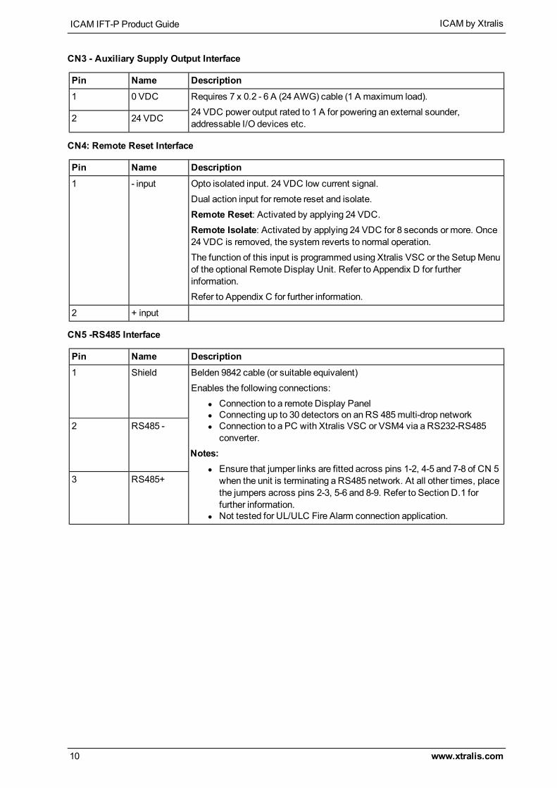
CN3 - Auxiliary Supply Output Interface
Pin Name Description1 0 VDC Requires 7 x 0.2 - 6 A (24 AWG) cable (1 A maximum load).
24 VDC power output rated to 1 A for powering an external sounder,addressable I/O devices etc.2 24 VDC
CN4: Remote Reset Interface
Pin Name Description1 - input Opto isolated input. 24 VDC low current signal.
Dual action input for remote reset and isolate.Remote Reset: Activated by applying 24 VDC.Remote Isolate: Activated by applying 24 VDC for 8 seconds or more. Once24 VDC is removed, the system reverts to normal operation.The function of this input is programmed using Xtralis VSC or the SetupMenuof the optional Remote Display Unit. Refer to Appendix D for furtherinformation.Refer to Appendix C for further information.
2 + input
CN5 -RS485 Interface
Pin Name Description1 Shield Belden 9842 cable (or suitable equivalent)
Enables the following connections:l Connection to a remote Display Panell Connecting up to 30 detectors on an RS 485multi-drop networkl Connection to a PC with Xtralis VSC or VSM4 via a RS232-RS485
converter.Notes:
l Ensure that jumper links are fitted across pins 1-2, 4-5 and 7-8 of CN 5when the unit is terminating a RS485 network. At all other times, placethe jumpers across pins 2-3, 5-6 and 8-9. Refer to Section D.1 forfurther information.
l Not tested for UL/ULC Fire Alarm connection application.
2 RS485 -
3 RS485+

ICAM by Xtralis ICAM IFT-P Product Guide
www.xtralis.com 11
CN7 - Output Relay Interface
Group Pin Name DescriptionFIRE 2 1 COM Requires 7 x 0.2 - 6 A (24 AWG) cable
Fault Relay OutputActivates when a Fault is detected.Alarm Relay OutputsAlarm relays for each Alarm level (Alert, Action, Fire 1, Fire 2) thatare activated when the corresponding alarm level is detected.Notes:
l Maximum relay contact rating is 2 A@ 30 VDC.l Refer to Section A.1 for further information.l Refer to Appendix C for further information.l NC (Normally CLOSED) and NO (Normally OPEN) refers to
unpowered state of relay. In normal non-fault condition theFAULT relay is powered so NC is OPEN and the NO isCLOSED. Refer to Appendix B for further information.
2 NC
3 NO
FIRE 1 4 COM
5 NC
6 NO
ACTION 7 COM
8 NC
9 NO
ALERT 10 COM
11 NC
12 NO
FAULT 13 COM
14 NC
15 NO
Note: Connection CN14 is only used for special applications.
Connections to RABBIT Processor Board
Connector Pin Description Description8-pin RJ45 Standard Ethernet
connectionsStandard Ethernet cable.Notes:
l Refer to Section D.1.1 for further information.l Not tested for UL/ULC Fire Alarm connection application.
Connections from 4 Channel Relay Board (Optional Module)
Output Relay Interface (i606)1 RELAY 1 C Requires 7 x 0.2 - 6 A (24 AWG) cable.
Notes:l Maximum relay contact rating is 2 A@ 30 VDC.l Refer to Appendix D for further information.
2 NC
3 NO
4 RELAY 2 C
5 NC
6 NO
7 RELAY 3 C
8 NC
9 NO
10 RELAY 4 C
11 NC
12 NO

ICAM IFT-P Product Guide ICAM by Xtralis
12 www.xtralis.com
Connections from Current Output Board (Optional Module)
Output Connections (i624)1 Output 1 + All outputs have the following specifications:
l 20 VDC max.l 4 - 20mA output current (optional 0 - 20mA)l 7 x 0.2 - 6 A (24 AWG) cable
Note:Refer to Appendix D for further information.
2 -
3 Output 2 +
4 -
5 Output 3 +
6 -
7 Output 4 +
8 -
9 Output 5 +
10 -
11 Output 6 +
12 -
13 Output 7 +
14 -
15 Output 8 +
16 -

ICAM by Xtralis ICAM IFT-P Product Guide
www.xtralis.com 13
2.3 Connection of Air Sampling NetworkNote: Formore details please refer to the ICAM Pipe InstallationManual.There are several common guidelines that should be followed when attaching the pipe network to the IFT-Pdetector:
l Pipes must NEVER be glued to the inlets of the detectorl Pipe network itself MUST be glued togetherl Use removable unions where necessary
Caution: Do not insert ANY object into the inlet ports other than the correct size of piping. This is to avoiddamage to delicate electronic flow sensor components mounted just inside each port opening.
Other pipe and inlet specifications are addressed in the following table.Table 2-1: Detector Inlet to Pipe Network Termination Specifications
Detector Inlet Port Acceptable Pipe orAdapter
Maximum PipeLength
Other Considerations
IFT-P 25mm (1in.)outer-diameterUPVC tubes
25mm (1in.); or
26.7mm (1.05in.) with 25(1in.) to 26.7mm(1.05in.) adaptors
2 x 100m (328ft.) -

ICAM IFT-P Product Guide ICAM by Xtralis
14 www.xtralis.com
2.4 Starting UpAfter installation, it will be necessary to power up the system for configuring the detector according to siterequirements and also to ensure that the detector and associated pipe network are properly installed.
l The system takes approximately 30 seconds to power up.l If the system or any detector on the network fails to power up, re-check that all power wires are
securely connected to their respective terminals and the polarity is correctly maintained.The detector may show faults immediately after power up and this is normal. Reset the detector to unlatch therelays and fault LEDs. The Fault LEDs on any display connected to the system will light up (this is normal).
2.5 ConfigurationThe configuration of the detector is achieved by using the following:
l PC loaded with Xtralis VSC or VSM4 software. Refer to the online help file.l Remote Display Unit. Refer to Appendix D for further information.
2.5.1 Flow NormalizationFlow normalization is necessary for the detector to learn the air flow characteristics of the system.Normalizationmay be achieved using Xtralis VSC or VSM4 software or a Remote Display Unit, and takesabout 6minutes. It is advised that the user does not try to change any settings during the normalizationprocess.Air-flow is directly affected by the fan speed in wide bore systems. The fan speed is programmable from 3 to10. It is recommended that it be left at 5 unless otherwise advised (e.g. long pipe lengths).Once the pipe work has been completed it is necessary for the unit to learn the values of flow rates at eachinlet. Once done, all displayed flow rates will be normalized to 100%.
To normalize the air flow for a detector using Xtralis VSC:
1. Remove the Front Cover.2. Connect the detector to a PC running Xtralis VSC. Refer to Section 1.6 for further information.3. Log into the detector as the administrator (ADM) user.4. Select Normalize Air Flow from the DeviceMenu.5. Wait for 10minutes.
To normalize the air flow for a detector using Remote Display Unit:
l Refer to Appendix D for further information.

ICAM by Xtralis ICAM IFT-P Product Guide
www.xtralis.com 15
3 MaintenanceNote: Routine tests should be carried out by qualified personnel.
3.1 InspectionThe following steps should be carried out in accordance with local codes and standards:
1. Check control panel for fault indications etc.2. Record results in system log book & report any abnormal results
The following page gives information on the servicing tests to be carried out on the detector. Servicingmustonly be carried out by trained or authorized personnel.
3.2 ServicingNote: Servicing should only be carried out by trained service contractors.Ensure that all relevant site personnel & supervising authorities have been informed and, where necessary,the system has been isolated from themain building alarm system before undertaking any actions whichmayresult in Alarm and/or Trouble/Fault conditions.
Service Description Servicing Interval(Months) >
Notes
6 12 18 24 30 36 42 48Check control panel for faults X X X X X X X X
Using Xtralis VSC, check data logs & recordmainevents (Faults/Alarms etc.)
X X X X X X X X
Check flow readings and record values X X X X X X X X
Physically inspect installation (Pipework & Cabling) X X X X X X X X
Inspect fuses and ensure correct ratings X X X X X X X X
Replace detector filter elements & clean chamber* X X X X X X X X
Replace internal filters* X X X X X X X X
Inspect and clean/replace in-line & end of line filters* X X X X X X X X
Normalize flow (due to replacement of filter elements) X X X X X X X X
Record flow values for each channel X X X X X X X X
Test optional accessories etc. X X X X X X X X Remote Display,Relays etc.
Record results in system log book X X X X X X X X
Complete servicing certificate and issue to user X X X X X X X X
Cleaning and filter change intervals are dependent on environmental conditions. The above recommendationsare based on typical office environments and the frequency may need to be increased for harsherenvironments.

ICAM IFT-P Product Guide ICAM by Xtralis
16 www.xtralis.com
This page is intentionally left blank.

ICAM by Xtralis ICAM IFT-P Product Guide
www.xtralis.com 17
4 Specifications4.1 Power
Supply Voltage 20 - 30 VDC Working *
Power Consumption (min) -
Power Consumption (max) 30W
Note: Power Supply Connection: For use in Fire Alarm Application, refer to Appendix C.* Product UL listed with 24 VDC Nominal Supply Voltage
4.2 CaseDimensions 254mm x 180mm x 165mm
(10.0 in. x 7.1 in. x 6.5 in.)
IP Rating IP30
4.3 Operating ConditionsAmbient 0°C to 39°C (32°F to 103°F) *
Tested to -10°C to 55°C (14°F to 131°F) *
Sampled air -20°C to 60°C (4°F to 40°F) *
Humidity (non-condensing) 10% to 95%
Note: Please consult your Xtralis office for operation outside these parameters or where sampled air iscontinually above 0.05% obs/m (0.015% obs/ft) under normal operating conditions.
* Product UL listed for use from 0 °C to 38 °C (32 °F to 100 °F)
4.4 Sampling NetworkPipe Size Outer Diameter: 1 in.
Pipe Length 2x100m (2x328ft) sampling pipe
Area Covered VdS:2,000m² (21,500 ft²)UL:850m² (9,150 ft²)
4.5 InterfacesPower Power In
Relays 4 Alarm Relays, 1 Fault RelayRated 1 A@ 30 VDC NO/NC Contacts

ICAM IFT-P Product Guide ICAM by Xtralis
18 www.xtralis.com
4.6 AlarmRange 0.001 to 20% obs/m
(0.0003 to 6.10% obs/ft)UL / ULC
l Special applications sensitivityrange is 0.001%/m – 1.6%/m(0.0003%/ft to 0.50%/ft). (ForSpecial Application it is requiredobtain approval from the LocalAuthority Having Jurisdiction).
l Open Area applications sensitivityrange is (1.6%/m – 12.0%/m) or0.5%/ft to 4%/ft
Levels Alert, Action, Fire1, Fire2Individually programmable for each level
4.7 CommunicationProtocols Modbus over RS232, RS485 and TCP/IP
Note: Not tested for UL/ULC Fire Alarmconnection application.

ICAM by Xtralis ICAM IFT-P Product Guide
www.xtralis.com 19
A Input-Output ModulesIFT-P detectors have 5 relays fitted as standard. The I/O functionality may be extended by adding I/Omodules. These plug onto the standard I/Omodule in a stackable chain of up to 3 positions. They arerecognized by the processor as Modules 1 to 3 going from left to right. When installing new modules, the typemust be entered in the Setupmenu in order to be correctly recognized. Somemodules, such as the 4 ChannelRelay Module, can be individually programmed under Configurationmode.
A.1 4-Channel Relay ModuleRelay module is configured using Xtralis VSC.The optional Remote display may also be used as follows:
1. After installing the relay module check that MOD1 in the Engineeringmenu has now changed to 1.(This is different for other types of cards)
2. In Setupmenu, changeMOD1 to 1 (if using a different card use the number that appears in theEngineeringmenu).
3. In the Configurationmenu set MOD1 to a number from 1 to 6 representing the triggering event where:1 = Alert2 = Action3 = Fire14 = Fire25 = Flow fault6 = General Fault
All four relays on the card will now activate for this event with respect to their corresponding sector.
Figure A-1: Relay ModuleSingle pole double throw (SDPT) contacts are used in the relay modules with a rating of 2 A at 24 VDC.

ICAM IFT-P Product Guide ICAM by Xtralis
20 www.xtralis.com
A.2 8-Channel, 4 - 20mA Output ModuleThe 8-Channel Output Modulemay be used for retransmission of airflow or smoke levels.Note: Not tested for UL/ULC Fire Alarm connection application.
Figure A-2: 8-Channel, 4 - 20mA Output ModuleTable A-1: 8-Channel Module Specifications
Description Value
Number of analog current outputs 8
Maximum output voltage 20 V
Output current 4 - 20mA (optionally 0 - 20mA)
Resolution 16 bits
Maximum Integral Nonlinearity ±0.012%
Maximum Offset ±0.05%
Maximum total output error ±0.15%
Output update rate 1 per second; all 8 outputs updatedsynchronously
Fault reporting Detects a high load resistance (e.g. anopen circuit) on any output.
Note: Unused outputs must have a load connected; otherwise the open circuit will be seen as a fault. Aresistor value in the range from 0 to 500Ω is suitable.

ICAM by Xtralis ICAM IFT-P Product Guide
www.xtralis.com 21
The AnalogueOutput Module is configured using Xtralis VSC.The optional remote display may also be used as follows:
Table A-2: 8-Channel Output Module Configuration Parameters
Menu Item Parameter ValueSETUP (MODULE n) Set to ANOUT 8
CONFIGURE (MOD n) According to 1 e.g. SMOKE X
(GAIN X) Applies to Smoke only.G = A/Owhere:
l G = Gainl A = Maximum Output Currentl O = Obscuration reading
corresponding to maximumoutput current
Examples:l Set GAIN X to 1 for 20%/m
(1 = 20mA / 20%/m)l Set GAIN X to 10 for 2%/m
(10 = 20mA / 2%/m)l Set GAIN X to 100 for 0.2%/m
(100 = 20mA / 0.2%/m)
To access the Setupmenu, follow these steps:1. Press MENU.2. Use ParameterUP & DOWN buttons to reachSETUP.3. Press ENTER.4. Use ValueUP & DOWN buttons to enter the Level 2 Access Code.
To access the Configuremenu, follow these steps:1. Press MENU.2. Use ParameterUP & DOWN buttons to reachCONFIGURE.

ICAM IFT-P Product Guide ICAM by Xtralis
22 www.xtralis.com
This page is intentionally left blank.

ICAM by Xtralis ICAM IFT-P Product Guide
www.xtralis.com 23
B Detector Wiring Diagram Examples
FAULT RELAY
OUTPUT
0V +V C NO NC
FAULT RELAYOUTPUT
24V
0V
VBAT
-+
-+
-+
AU
X 2
4V
RE
SE
T
-+
SH
IEL
D
RS
48
5
CN
3C
N5
CN1
CN2
CN7
RS232
FIR
E 2
FIR
E 1
AC
TIO
NA
LE
RT
FA
ULT
CO
MN
CN
OC
OM
NC
NO
CO
MN
CN
OC
OM
NC
NO
CO
MN
CN
O
1
2
1
2
1
2
1
2
3
1
2
3
4
5
6
7
8
9
10
11
12
13
14
15
Detector
I/O BOARD
POWER SUPPLY PCB
OUTPUT 1
0V +V
+V 0V
0V
+
V 0
V +
V
0V
+
V
FUSE
BOARD
VPS-250-E
OUTPUT 2 OUTPUT 3 OUTPUT 4
Figure B-1: Fault Relay - Closed for Normal

ICAM IFT-P Product Guide ICAM by Xtralis
24 www.xtralis.com
FAULT RELAY
OUTPUT
0V +V C NO NC
FAULT RELAYOUTPUT
24V
0V
VBAT
-+
-+
-+
AU
X 2
4V
RE
SE
T
-+
SH
IEL
D
RS
48
5
CN
3C
N5
CN1
CN2
CN7
RS232
FIR
E 2
FIR
E 1
AC
TIO
NA
LE
RT
FA
ULT
CO
MN
CN
OC
OM
NC
NO
CO
MN
CN
OC
OM
NC
NO
CO
MN
CN
O
1
2
1
2
1
2
1
2
3
1
2
3
4
5
6
7
8
9
10
11
12
13
14
15
DETECTOR
I/O BOARD
POWER SUPPLY PCB
OUTPUT 1
0V +V
+V 0V
0V
+
V 0
V +
V
0V
+
V
FUSE
BOARD
VPS-250-E
OUTPUT 2 OUTPUT 3 OUTPUT 4
Figure B-2: Fault Relay - Open for Normal

ICAM by Xtralis ICAM IFT-P Product Guide
www.xtralis.com 25
C UL/ULC Wiring RequirementsThis chapter covers the UL/ULC Wiring Requirements for Fire Alarm Connection Application.
CN3
CN4
CN5
CN2
+
_
_
+
_
+
CN7
CN6
1
2
3
4
5
+_
1
2
1
2
1
2
3
1
2
3
4
5
6
7
8
9
10
11
12
13
14
15
EOL
A C
B
Figure C-1: ULC input and output requirements1. 24 VDC input power applied to terminals 1 & 2 of CN2 as shown in item A above. 24 VDC supply shall
be a ULC-527 Listed Fire Alarm Control Panel or ULC-527 Listed power supply.2. For connection to Analog addressable systems -monitoring of Alarm and Fault relay outputs are to be
connected as item C above (as aminimum). Optionally, there are an additional 3 relay outputscorresponding to thresholds - Alert, Action and Fire 2 which can bemonitored also. Additionaladdressable contact monitoring devices would be used tomonitor those output contacts as needed.
3. For Conventional Initiating device circuits – wiring of alarm and fault contacts shall be wired as shownin item C above (as aminimum. Optionally there are 3 additional thresholds available (Alert, Action &Fire 2) which can bemonitored also. These would require the use of additional Initiating circuits fromthe conventional control panel.
4. Additionally in either case above (Addressable or conventional interfaces) a remote reset input isrequired to reset latched Alarm and Fault conditions on the unit. An external reset device would beconnected between CN3 & CN4 terminals as shown in item B above. This input will reset when the firealarm control panel is reset clearing all latched Faults and Alarms.
5. Installation of detectors shall meet all applicable requirements of the following:
a. Standard for the Installation of Fire Alarm System - CAN/ULC-S524b. National Building Code of Canada.c. National Fire Code of Canada
Table C-1: Connections for i602 I/O Board
CN2: DC Supply
1 24 VDC in Requires 16 x 0.25-15 A (18 AWG) cable (0.75mm² minimum IEC60227 H05 W-F/H05 WH2-F2 for EC).
Note: Link Pin 2 (0 V) and Pin 5 (MAINS/BAT).2 0 VDC in
3 N/C
4 N/C
5 Mains/Battery
CN4: Remote Reset Interface
1 - input Opto isolated input. 24 VDC low current signal.
2 + input

ICAM IFT-P Product Guide ICAM by Xtralis
26 www.xtralis.com
CN7: Output Relay Interface
1 FIRE 2 C Requires 7 x 0.2 - 6 A (24 AWG) cable
Note: Maximum relay contact rating is 2 A @ 30 VDC.
Note: Refer to section A.1 for further information.2 NC
3 NO
4 FIRE 1 C
5 NC
6 NO
7 ACTION C
8 NC
9 NO
10 ALERT C
11 NC
12 NO
13 FAULT C
14 NC
15 NO

ICAM by Xtralis ICAM IFT-P Product Guide
www.xtralis.com 27
D Remote Display UnitThe Remote Display Unit (RDU) allows the IFT family of aspirated smoke detection systems to bemonitored,controlled and programmed remotely. RS485 communication is used between the detector and the remotedisplay unit. The remote display unit can be simply configured tomonitor any one of the detectors on thenetwork.
Figure D-1: Remote Display Unit
D.1 Installation and ConfigurationD.1.1 Cabling RequirementsInstallation Guide for RS485 Equipment
Communications to RS485 standard are designed to reject a degree of interference, but caremust still betaken when designing and implementing the installation tominimize the level of interference imposed on theequipment. To prevent damage due to tropical storms and other sources of large external currents andvoltages, additional surge absorbing components may be required as part of the installation.It is the responsibility of the installer to provide a suitable environment to prevent damage to the equipment,and to reduce external interference to a level within which the equipment can operate as defined by itsspecification. The provision of warning, caution and danger information to the end user is within the task of theinstallation provider, and not the instrument manufacturer.The purpose of the guide is to assist the installation provider, but it is not intended to be a full and complete setof instructions. The installer shall bemore qualified to take the relevant technical, safety and legal decisions.
Electrical Supply
The supply voltage and frequency must bemaintained within the equipment requirement specification. Anybreaks in supply or reductions in voltage below the specifiedminimum will result in equipment shutdown.When this problem exists, an uninterruptible power supply should be used to supply the equipment.If the electrical supply is known, or suspected, to be subject to noise pulses produced by motors, fluorescentlamps, storms and lightning, or other causes thenmains filteringmust be fitted to reduce the peak amplitudeto less than twice the nominal RMS voltage.The equipment metal casemust be connected to an earth. To protect personnel this earth should be free fromvoltages greater than 10 V peak.

ICAM IFT-P Product Guide ICAM by Xtralis
28 www.xtralis.com
It is recommended that galvanically isolated power supplies (in accordance with UL1481) are used since theRS485 inputs/outputs are not usually isolated from the equipment internal zero volt line.The RS232/RS485 converter should also be galvanically isolated.
Cable Material
RS485 communication is by current switching between a pair of wires at data rates of up to 250 kbps.The cable construction is specified as:
l Twisted pair of nominal 10 turns per meter or yardl 40 pF to 60 pF meter between conductorsl 100Ω to 120Ω characteristic impedancel Maximum signal attenuation over total length 16 dB at 0.25MHzl Overall screen (to be connected at one end only)
The cablematerials are not specified, but in order to meet the low capacity specificationpolyethylene/polyolefin/polypropylene is used as the insulator, with PVC/flame retardant PVC as the overallsheath. Other materials can be used if the impedance and capacity requirements aremet.Installation requirements may add other features, such as fire resistance, flame retardance, UL approval, lowsmoke and fume etc.Also remember to check that the electrical characteristics of the cable used is appropriate for the wiringdistance required for the installation.Common ModeThe RS485 inputs/outputs are not usually isolated from the equipment internal 0 V line. Themaximumpotential difference between the 0 V lines of all instruments connected to an RS485 communication cable islimited by the specification to between -7 V and +12 V. If this limit is exceeded, communications will be lost.
Interference Induced onto CableTwisted pair construction and cable screens do not completely shield the communication link from externalelectromagnetic interference (EMI). Good practice should be followed when installing communication cablesto eliminate EMI.RS485 cables should not be installed in the same duct/tray as power cables, or switching cables. WhenRS485 cables cross power or switching cables, this should be at right angles. RS485 should not be installedin areas of high interference, where this is not possible, then electro-magnetic screeningmust be adopted forexample, metal conduit or cable tray could be used.The total length of the cable runmust not exceed 1200m (4000 ft). It is only possible to exceed this length byuse of repeater units to re-generate the signal.Terminating CablesIt is imperative that the cable structure is maintained to a position as close as possible to the termination. Thisis to maintain the interference protection and reduce losses due to changes in cable impedance.The outer sheath and screenmust not be cut-back for a distance of more than 100mm (4 in.) from thetermination.The twisted pair must not be untwisted for a distance of more than 25mm (1 in.) from the termination.The recommended cablemanufactured to RS485 specifications is: BELDEN 9841/9842 (or equivalent) - 24AWG, polyethylene insulation, PVC sheath, UL style number 2919.
l 9841 Single twisted pair: communications data onlyl 9842 Double twisted pair: 1 pair for communications data, 1 pair for 24 V supply.
Please ensure that electrical characteristics are sufficient for the distance of connection betweendevices.

ICAM by Xtralis ICAM IFT-P Product Guide
www.xtralis.com 29
D.1.2 Remote Display Unit Connection
1. Jumper Link2. RS4853. 24 VDC power
Figure D-2: Display board and terminal for remotely connecting the Remote Display UnitTable D-1: Connections to Remote Panel (Optional) i620 Control Board
RS485 Remote Control Data1 +24 VDC (Supply Out) Belden 9842 (24 AWG) cable (or equivalent)
2 0 V (Supply Common) Notes:l Ensure that a jumper link is fitted across pins 1-2 of CN 6.l Refer to Section D.1.2 for further information.
3 RS485 +
4 RS485 -
Notes:l Refer to Appendix D for further information.l Not tested for UL/ULC Fire Alarm connection application.
Note: Ensure that a jumper link is fitted across pins 1-2 on CN 6.Suitable 2 pair twisted pair cable (e.g. Belden 9842) for connecting RS485 communications and 24 VDCpower can also be supplied. Refer to Section D.1.1 for further information. Ensure that the electricalcharacteristics of the cable connected are appropriate for the distance between the detector and displaymodule.When using the cable, use one pair for RS485 communications, the other pair for 24 VDC supply, and ensurethat matching signals are connected at each end.

ICAM IFT-P Product Guide ICAM by Xtralis
30 www.xtralis.com
D.1.3 Starting UpDuring power-up, the following sequence of events occurs:
l Sounder beepsl Aspirator or Pump startsl Display shows a rolling text message showing:
l IFT-Pl Software version: VERSION *.**l Optional text 1l Optional text 2l Optional text 3
l Fault indicators are activated for current faultsl Current smoke background level (% obs/m) is displayed
Optional text information are user definable options differing from the factory default settings:1. REM PANEL - the unit may be configured to operate the display panel remotely using the RS485
communications.2. NODET FLOW - the flow measurement through the detector chamber itself may be disabled
D.1.4 Remote Display OperationThe IFT-P must be configured to communicate with the Remote Display Unit using the Xtralis VSC. Refer tothe Xtralis VSC online help for further information.

ICAM by Xtralis ICAM IFT-P Product Guide
www.xtralis.com 31
D.2 Remote Display Unit Navigation
Figure D-3: Remote Display Unit Navigation

ICAM IFT-P Product Guide ICAM by Xtralis
32 www.xtralis.com
D.3 Remote Display Unit Button FunctionsNote: This section covers all functions available to the Remote Display Unit. Some of these functions are
not applicable to the IFT-P.This section provides information on the functions of the buttons in the Remote Display Unit, and how tosetup the detector and navigate through theMainMenu options. Refer to Section D.2 for further information.
Figure D-4: Buttons for user functions
Access Codes
Access to somemodes in theMainMenu and other configuration and control functions requires the user toenter an Access Code.There are several different access levels. Higher levels provide access to additional administration features.TheOperator Access Code is changeable as a parameter in ConfigurationMode, which requires Level 1Access. The default Access Codes are shown below.
Table D-2: Detector Access Codes
Access Level Access Code
Operator 0
Level 1 260
Level 2 693
Level 3 Factory UseOnly
How to Enter an Access Code via the Remote Display UnitWhen entering an Access Code, the alternative function LEDs above the ACCEPT and RESET buttons willbe lit, enabling these buttons to be used as UP and DOWN buttons to enter a 3-digit number.If the UP or DOWN buttons are continually pressed, the 'units' digit on the Status Display will be activated,then the 'tens' digit, then the 'hundreds' digit. If the button is released, the flashing digit (units, tens orhundreds) is the one that will change with further use of the UP and DOWN buttons. When the hundreds digitis correct, wait about five seconds for the flashing digit to move to the tens digit, then set the tens to therequired value. Repeat for the units digit.

ICAM by Xtralis ICAM IFT-P Product Guide
www.xtralis.com 33
User Functions
User functions associated with some configuration and control buttons are described in this section.Table D-3: Description of User Functions for the Remote Display Unit
Function Access Level Description
ACCEPT None Acts only on the internal sounder. Acknowledges all current Alarm states.All other warning mechanisms continue unchanged. Sounder operationchanges from continuous to 1 second ON: 15 seconds OFF. New Alarmevents cause the sounder to revert to continuous operation.
SOUNDERSILENCE
Operator Acts only on the internal sounder. The Sounder is switched off until one ormore new Alarm events.
RESET Operator Clears all latched Alarms and Faults. Current Alarms or Faults will remain.
ISOLATE Operator Used when diagnosing faults, testing new installations etc. All alarmrelays are disabled, so that Alarm conditions will not be reported back tothe Host Panel. The Isolate button toggles the unit between Isolated andNormal operation, as shown by the Isolated indicator, but see note below.
Notes:l If the unit is isolated then returned to the Normal, Locked state (by
pressing the MENU button) the Operator will need to re-enterOperator Access Code in order to cancel the isolated state.
l If a power cycle is applied to the detector, the detector will notremain in an isolated state.
TEST None Successive presses of the Test button show:
1. Date on the Status Display2. Time on the Status Display3. IP address on the Status Display4. Subnet net mask on the Status Display5. Media Access Control (MAC) address on the Status Display6. All activated LEDs on the panel and LED segments on the Status
Display7. Normal display
The IFT-P detector can also be reset remotely by applying 24 VDC to the remote reset input on theMain I/OPCB. Refer to section 2.2.1 for further information.Note: When theOperator Access Code is entered (default = 0), the Sounder Silence, Reset and Isolate user
functions are enabled and the unit is placed in the Unlock state, as shown by the flashing Unlockindicator. If the unit is isolated, then returned to the Normal, Locked state (by pressing theMainMenubutton) the Operator will need to re-enter Operator Code in order to cancel the Isolated state. If anybutton is not pressed to lock the panel the unit will self-timeout and lock in 5minutes.

ICAM IFT-P Product Guide ICAM by Xtralis
34 www.xtralis.com
Main Menu Modes
To enter one of theMainMenuModes follow these steps:1. Press MENU2. Use FunctionUP & DOWN buttons (SCAN and ISOLATE buttons) to reach requiredmainmenu item3. Press ENTER (SOUNDER SILENCE button)4. Use ValueUP & DOWN buttons (RESET and ACCEPT buttons) to enter the appropriate Access
Code5. Press ENTER
Notes:l Access Code Entry may be aborted by pressing theMENU button.l All of the following settings can be entered using the Xtralis VSC configuration software and a PC. This
can reduce the time taken to enter certain values and parameters.To obtain this software contact Xtralis or visit the website www.xtralis.com.
The following sections show how to enter theMainMenuModes and what parameters are available in each ofthesemodes.
FAULTS: Fault List
Minimum Access Level Required: NoneThis menu item shows a list of the current faults that are not already annunciated via a Remote Display UnitLED.Use the Function UP & DOWN buttons (Isolate and Scan) to inspect any current fault in the list.
OPERATOR: Operator Mode
Minimum Access Level Required: OperatorThis menu item enables the user to specifically enter Operator Mode, and permits the usage of the Isolate,Sounder Silence and Reset buttons. Once the user has successfully entered theOperator Access Code, theUnlock LED should activate.
ENGINEERING: Engineering Mode
Minimum Access Code Required: NoneCertain engineering values may be inspected, primarily for diagnostic purposes. Use the UP & DOWNbuttons (Isolate and Scan) to inspect any parameter in the list.
Table D-4: Engineering Parameters and Values
Parameter Value Description
VERSION *.** Version of Software in the processor module in theMain Unit. The softwarecan be upgraded using a PC and a special interconnect lead.
BUILD NO *.** Reference to specific software build.
GENERALFAULT
*.** Fault list that generates fault number codes.
DETFLOW **.*% Sample flow through the detector. This measurement may beenabled/disabled under Configuration.
FLOWnn **.*% Measurements of Sample flow rate. The flow rates should be normalized to100% at installation.
BATTERY **.* V N/A
OBS/M orOBSC/FT
*.**% Obscuration value inmeters or feet. This is the same as the normal display.
MODn 1 to 5 Shows themodule types that are fitted. These are read directly from theModules.

ICAM by Xtralis ICAM IFT-P Product Guide
www.xtralis.com 35
CONFIGURE: Configuration Mode
Minimum Access Code Required: Level 1The IFT-P detector uses many configuration parameters, and is shipped with factory default values. TheConfigurationMode allows changes to bemade to these parameters. Below is a list of user definableparameters, and their Factory Default values. The ParameterUP andDOWN buttons (Isolate and Scan)navigate through the list; the ValueUP andDOWN buttons (Accept and Reset) change the value. TheENTER button (Sounder Silence) saves the new value, andmoves to the next parameter.

ICAM IFT-P Product Guide ICAM by Xtralis
36 www.xtralis.com
Table D-5: ConfigurationMode Parameters and Values
DisplayPanel
Shorthand
Parameter Range Factory Default
OPCODE Operator Function Access Code 0 to 999 0
ENDSCTR End Sector (number of sectors used) 1 - default
DENSLOG Log of density change 0.01 to 20.00 0.02
F2LTCH Fire 2 Latch 0 or 1 1
F1LTCH Fire 1 Latch 0 or 1 1
ACTLTCH Action Latch 0 or 1 1
ALTLTCH Alert Latch 0 or 1 1
TRCLTCH Trace Latch 0 or 1 1
FLTLTCH Fault Latch 0 or 1 1
TRCRLY Trace Relay 1 0 or 1 0
FLOWDEL Flow Fault Delay 1 to 60s 5s
FLOWHI Flow High Limit 105 to 200% 120%
FLOWLO Flow Low Limit 0 to 95% 80%
FLOWLOG Log of flow change 0.0 to 200.0 5.0
SETFAN Set Fan Speed 3 to 10 5
BUZZER Internal Sounder Enable 0 or 1 1
BEACON Beacon Enable 0 or 1 1
ADDRESS RS485 Address 0 to 30 31 (off)
TESTTIM Time between automatic scansNote: TESTIM is also used for IFT-15 Flownormalization by pressing ENTER
0 to 20160mins 1440
MIN DWELL Rotary valve dwell time 0 to 60s 0s
GAIN X See description
MOD1 Set Module 1 usage
MOD2 Set Module 2 usage
MOD3 Set Module 3 usage
MOD4 Set Module 4 usage
MOD5 Set Module 5 usage
SC DEL Suppression Control Delay 0 to 120 60
NIGHSTART Night Start time (Hour in 24 format) 12 to 23 12
NIGHSTOP Night Stop time (Hour in 24 format) 0 to 12 12
TRC PRESS Setup for auto Valve Scan 5 to 1000 25
Notes:l Avoid setting to values already defined for Level 1 or 2 Access Codes.l To revert all Configuration parameters to their default values go to the LOAD DEFAULTSmenu item
and press ENTER (Level 2 Access Code is required). The Unit will restart with default parameters.
ICAM by Xtralis ICAM IFT-P Product Guide
www.xtralis.com 37
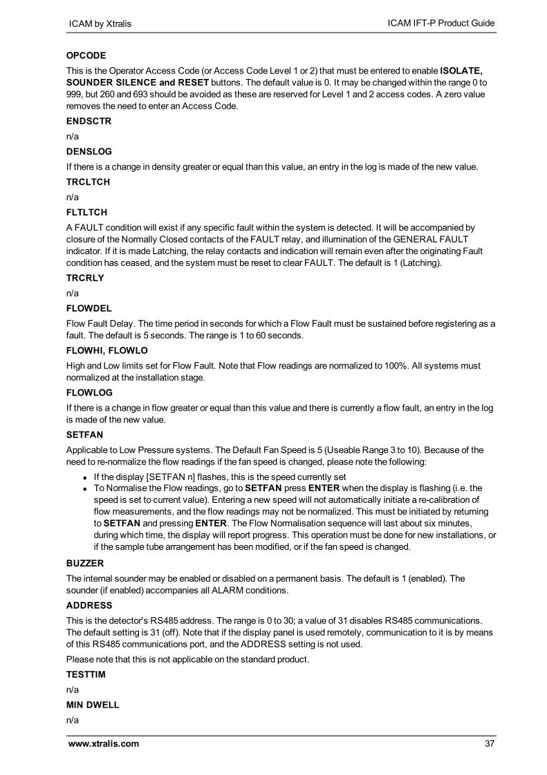
OPCODEThis is the Operator Access Code (or Access Code Level 1 or 2) that must be entered to enable ISOLATE,SOUNDER SILENCE and RESET buttons. The default value is 0. It may be changed within the range 0 to999, but 260 and 693 should be avoided as these are reserved for Level 1 and 2 access codes. A zero valueremoves the need to enter an Access Code.ENDSCTRn/aDENSLOGIf there is a change in density greater or equal than this value, an entry in the log is made of the new value.TRCLTCHn/aFLTLTCHA FAULT condition will exist if any specific fault within the system is detected. It will be accompanied byclosure of the Normally Closed contacts of the FAULT relay, and illumination of the GENERAL FAULTindicator. If it is made Latching, the relay contacts and indication will remain even after the originating Faultcondition has ceased, and the systemmust be reset to clear FAULT. The default is 1 (Latching).TRCRLYn/aFLOWDELFlow Fault Delay. The time period in seconds for which a Flow Fault must be sustained before registering as afault. The default is 5 seconds. The range is 1 to 60 seconds.FLOWHI, FLOWLOHigh and Low limits set for Flow Fault. Note that Flow readings are normalized to 100%. All systems mustnormalized at the installation stage.FLOWLOGIf there is a change in flow greater or equal than this value and there is currently a flow fault, an entry in the logis made of the new value.SETFANApplicable to Low Pressure systems. The Default Fan Speed is 5 (Useable Range 3 to 10). Because of theneed to re-normalize the flow readings if the fan speed is changed, please note the following:
l If the display [SETFAN n] flashes, this is the speed currently setl ToNormalise the Flow readings, go toSETFAN press ENTER when the display is flashing (i.e. the
speed is set to current value). Entering a new speed will not automatically initiate a re-calibration offlow measurements, and the flow readings may not be normalized. This must be initiated by returningtoSETFAN and pressingENTER. The Flow Normalisation sequence will last about six minutes,during which time, the display will report progress. This operationmust be done for new installations, orif the sample tube arrangement has beenmodified, or if the fan speed is changed.
BUZZERThe internal sounder may be enabled or disabled on a permanent basis. The default is 1 (enabled). Thesounder (if enabled) accompanies all ALARM conditions.ADDRESSThis is the detector's RS485 address. The range is 0 to 30; a value of 31 disables RS485 communications.The default setting is 31 (off). Note that if the display panel is used remotely, communication to it is by meansof this RS485 communications port, and the ADDRESS setting is not used.Please note that this is not applicable on the standard product.TESTTIMn/aMIN DWELLn/a

ICAM IFT-P Product Guide ICAM by Xtralis
38 www.xtralis.com
GAIN XTheGAIN X setting is used to condition output signals from the 8 channel 4 - 20mA Output Module where it isset to measure Smoke (real time smoke density). Gain settings range from 1 to 100.TheGAIN X setting should be increased where the background smoke level is high, or decreased wherebackground smoke is low.Refer to section A.2 for further information.MOD1, MOD2, MOD3, MOD4, MOD5Somemodule types may be used in different ways. MOD1 toMOD5 sets the usage of thesemodules. Seeunder the specific I/Omodule section.SC_DELN/A.NIGHSTART, NIGHSTOPThe time in hours, on a 24 hour basis, at which the values change from day to night or back again. The defaultvalue for both is 12, at this value only the day values are applicable.TRC PRESSn/a
SECTORS ALARMS: Set Sector Day and Night Alarms
Minimum Access Code Required: Level 1The display will now show DAY VALUES, use ParameterUP & DOWN to change to NIGHT VALUES.Press ENTER to access the settings for all the sectors.This function allows the user to set different values for day and night operation. The time of day when thevalues change over is also configurable.

ICAM by Xtralis ICAM IFT-P Product Guide
www.xtralis.com 39
Table D-6: Sector Alarm Parameters and Values
Parameter Description Class A/B/CRange Default
ALL F2 All Fire 2 Alarm Levels 0.001-20% obs/m(0.0003-6.25%obs/ft)
1.00% obs/m(0.305%obs/ft)
ALL F1 All Fire 1 Alarm Levels 0.001-20% obs/m(0.0003-6.25%obs/ft)
0.08% obs/m(0.024%obs/ft)
ALL ACTION All Action Alarm Levels 0.001-20% obs/m(0.0003-6.25%obs/ft)
0.06% obs/m(0.018%obs/ft)
ALL ALERT All Alert Alarm Levels 0.001-20% obs/m(0.0003-6.25%obs/ft)
0.04% obs/m(0.012%obs/ft)
Sn FIRE 2n =1 to 15
Sector 'n' Fire 2 Level 0.001-20% obs/m(0.0003-6.25%obs/ft)
1.00% obs/m(0.305%obs/ft)
Sn FIRE 1n =1 to 15
Sector 'n' Fire 1 Level 0.001-20% obs/m(0.0003-6.25%obs/ft)
0.08% obs/m(0.024%obs/ft)
Sn ACTIONn =1 to 15
Sector 'n' Action Level 0.001-20% obs/m(0.0003-6.25%obs/ft)
0.06% obs/m(0.018%obs/ft)
Sn ALERTn =1 to 15
Sector 'n' Alert Level 0.001-20% obs/m(0.0003-6.25%obs/ft)
0.04% obs/m(0.012%obs/ft)
TRACE Trace Level 0.001-20% obs/m(0.0003-6.25%obs/ft)
0.03% obs/m(0.009%obs/ft)
FINAL SECTOR AS ABOVE
F2DEL Fire 2 Delay 0 to 60 secs 3 secs
F1DEL Fire 1 Delay 0 to 60 secs 3 secs
ACTDEL Action Delay 0 to 60 secs 3 secs
ALTDEL Alert Delay 0 to 60 secs 3 secs
TRCDEL Trace Delay 0 to 60 secs 3 secs
By default, NIGHT VALUES are set to the same as DAY VALUES. DELAYS are automatically the same forboth DAY and NIGHT.ALL ALERT, ALL ACTION, ALL F1, ALL F2These are the obscuration levels corresponding to the respective alarm events. Changes made shouldpreserve their progressive relationship.TRACEn/aALTDEL, ACTDEL, F1DEL, F2DELThe time period for which the corresponding obscuration levels must be sustained before triggering an alarm.Prevents spurious Alarm events.

ICAM IFT-P Product Guide ICAM by Xtralis
40 www.xtralis.com
TIME DATE: Set Time and Date
Minimum Access Code Required: Level 1
Figure D-5: Display for setting time and date.After accessing this menu item, the display will now show the date in the format 'day - date - month - year',with the date flashing. To change the time and date:
1. Press UP & DOWN buttons to change the date.2. Press ENTER to update the date andmove to the next step (month); month will flash.3. Press UP & DOWN buttons to change themonth.4. Press ENTER to update themonth andmove to the next step (year).5. Press UP & DOWN buttons to change the year.6. Press ENTER to update the year.
Continue as above to change the time. When theENTER button is pressed; the flashing element will progressfrom date through to seconds, with the display format changing from date to time appropriately. The day of theweek is determined from the date, month and year.The ParameterUP & DOWN buttons will switch the display between date and time.Return to theMainMenu by pressingMENU.
WEB: Set IP Address and Mask
Minimum Access Code Required: Level 1
Figure D-6: IP Address and IP Mask display - default values shown.The display will now show the text IP ADDRESS. Press UP button to show the IP Address with the first fieldflashing:

ICAM by Xtralis ICAM IFT-P Product Guide
www.xtralis.com 41
1. Use ValueUP & DOWN buttons to set the first field.2. Press ENTER to update andmove to the next field.3. Repeat the two steps for all fields.
Once the IP Address has been updated, the display will now show IP MASK. Press UP to show the actual IPMASK with first field flashing:
1. Use ValueUP & DOWN buttons to set the first field.2. Press ENTER to update andmove to the next field.3. Repeat the two steps for all fields.
Return to theMainMenu by pressingMENU.
SETUP: Setup Menu
Minimum Access Code Required: Level 2Once the SetupMode is accessed, please follow this procedure to change a parameter:
1. Press ParameterUP & DOWN buttons to reach requiredSETUP item.2. Press ENTER.3. Press ValueUP & DOWN buttons to update the item.4. Press ENTER to update andmove to next parameter. If the value is left unchanged, ENTER will have
no effect.Press MENU to get back to theMainMenu. Press MENU again to get back to Normal display.The Setupmenu has the following items.
Table D-7: SetupMenu Parameters and Values
Parameter Value Defaults Description
HI RESLTN 0 or 1 0 Enables the Status Display to show standard resolution (0) or higherResolution (1) for obscuration (switches between a resolution of 0.01to 0.001).
Note: It is highly recommended to leave this value at 0. Changing thevalue from 0 will cause some configuration values to change.Connection to Xtralis fire configuration and management software willautomatically change this value back to 0.
OBSC/FT 0 or 1 0 Set to 1 to display smoke value in % obs/ft. Normally % obs/m.
Note: Smoke Alarm Thresholds will revert to default values whenchanging between % obs/ft and % obs/m and vice versa.
REMPANEL 0 or 1 0 Enables remote panel operation. A communications fault will bedisplayed if this is enabled without a remote display connected.
REMPOD 0, 1 or 2 0 Set to 1 if a Remote Sensing Unit is connected.
Note: This option is not available for standard IFT-P devices.
DETFLOW 0 or 1 1 In addition to individual sector flow monitoring, detector flowmonitoring is also incorporated.Set to 1 to enable.
CCODE Country Code Refer to Table D-8 for further information.
RES-ISOL 0 or 1 1 Set to 0 to reset system with 24 V on reset line.
Set to 1 to isolate system when 24 V is applied for 8 seconds or more.Note: Once 24 V is applied, the system will initially reset. If 24 V is stillpresent after 8 seconds, the system will be isolated until 24 V isremoved (after which it will resume normal operation). If the 24 V isremoved before 8 seconds, the system will only reset and will not beisolated.
MOD1 to 5 List of available I/Omodules
All I/O modules fitted at build will have this information entered. Ifadditional I/O modules are installed, their type must be entered here.
The IFT-P detector can operate in a number of different languages. To change the language, the correctcountry code (CCODE)must be entered.

ICAM IFT-P Product Guide ICAM by Xtralis
42 www.xtralis.com
Table D-8: Country Codes
Language Code
English (default) 44
United States (English) 1
French 33
Spanish 34
Portuguese 35
Italian 39
German 49
LASER CAL: Laser Calibration
Minimum Access Code Required: Level 3This menu option is only available for factory use to calibrate the laser.
LOAD DEFAULTS: Load Defaults
Minimum Access Code Required: Level 2This menu option will enable the user to reload all factory defaults for all configuration parameters under theConfiguration and Sector Alarms menus. It is recommended that the system configuration is saved prior toapplying this menu option.
MAINTENANCE: Maintenance Mode
Minimum Access Code Required: NoneUse the Parameter UP & DOWN buttons (Isolate and Scan) to inspect any item in themaintenance list.
Table D-9: Maintenance Parameters
Parameter Description
LASERIN Current smoke value for the laser detector output
MOD1 IN Identification number of Module 1
MOD2 IN Identification number of Module 2
MOD3 IN Identification number of Module 3
MOD4 IN Identification number of Module 4
MOD5 IN Identification number of Module 5
TEST OUTPUTS: Testing Mode
Minimum Access Code Required: Level 2This menu item enables the user to manually increase or decrease smoke levels for the detector in order tosimulate a real fire event. This enables the user to test the responses of the detector to a fire event. Pleasenote that all alarms and relays will operate as if the system is reacting to a real fire event.