ic-m505 gmdss dsc radio simulatorhb9rxc.homeip.net/download/ic505/icm505.pdf · ic-m505 gmdss dsc...
TRANSCRIPT

IC-M505 Simulator V 1.0 Pag. 1
IC-M505 GMDSS DSC RADIO SIMULATOR
DISCLAIMER
THIS IS NOT A 100% REAL SIMULATION OF THE ICOM IC-M 505 VHF DSC TRANSCEIVER, AND SHOULD BE USED ONLY AS GENERIC EXAMPLE FOR TRAINING PURPOSES ONLY. MAY NOT MEET/RESPECT ALL INTERNATIONAL REQUIREMENTS, RULES OR REGULATIONS AS ITU R-493 AND OTHER SUBSEQUENT DEVELOPMENT OR AMENDEMENTS. IN NO EVENT SHALL REGENTS BE LIABLE TO ANY PARTY FOR DIRECT, INDIRECT, SPECIAL, INCIDENTAL, OR
CONSEQUENTIAL DAMAGES, INCLUDING LOST PROFITS, ARISING OUT OF THE USE OF THIS SOFTWARE AND ITS
DOCUMENTATION, EVEN IF REGENTS HAS BEEN ADVISED OF THE POSSIBILITY OF SUCH DAMAGE.
REGENTS SPECIFICALLY DISCLAIMS ANY WARRANTIES, INCLUDING, BUT NOT LIMITED TO, THE IMPLIED WARRANTIES OF
MERCHANTABILITY AND FITNESS FOR A PARTICULAR PURPOSE. THE SOFTWARE AND ACCOMPANYING DOCUMENTATION,
IF ANY, PROVIDED HEREUNDER IS PROVIDED "AS IS". REGENTS HAS NO OBLIGATION TO PROVIDE MAINTENANCE,
SUPPORT, UPDATES, ENHANCEMENTS, OR MODIFICATIONS.
COPYRIGHT 2016
Pietro Bossi
Via Vincenzo Vela 22
CH-6850 Mendrisio
!! USE AT YOUR OWN RISK FOR TRAINING PURPOSES ONLY !!

IC-M505 Simulator V 1.0 Pag. 2
REQUIREMENTS
• Personal computer with a Microsoft Windows operating system (tested on XP / W7 / W10).
• Ethernet or WIFI interface (necessary if you want to connect to other PC).
• Compatible Soundcard, speaker, microphone or headset.
• Mouse.
• Video resolution 1280x1024, 1920x1080 pixels or more recommended (16/32 bit color depth).
TECHNICAL NOTES • The simulator use the “UDP Broadcast“ protocol to communicate with the “Controller” and other copies
of simulator if installed on other PC.
• As result, it’s possible to connect as many PC as you want, running the same application (please setup
each radio with a different MMSI).
• To simulate real world situation, you may connect two PC directly via an Ethernet crossed-cable, or
connect more PCs via an Ethernet HUB or SWITCH (see drawing).
• Some firewall or antivirus programs may need to be configured to enable communications between PC
over the UDP ports 8090 / 8091 (see your software help for configuration).
CONNECTION EXAMPLES
1. Single PC installation:
2. Two PC cross-cable connection:
CONTROLLER
002740001
ICM-505 SIM
269000001
ICM-505 SIM
269000001
CONTROLLER
002740001
ICM-505 SIM
2370000091
Network mode
Stand-alone

IC-M505 Simulator V 1.0 Pag. 3
3. Multiple PC over Ethernet
ICM-505 SIM
269000001
CONTROLLER
002740001
ICM-505 SIM
2370000091
ICM-505 SIM
265000100
ICM-505 SIM
324123001

IC-M505 Simulator V 1.0 Pag. 4
IC-M505 RADIO SETUP
1. RADIO > MMSI : Your local radio MMSI. Should be a single and different on each radio. 2. RADIO > GROUP : Your group radio MMSI, to be called with a single MMSI. 3. RADIO > SHIP NAME : the station's name as displayed on the simulator status bar (optional). 4. RADIO > CALL SIGN : the station's call sign as displayed on the simulator status bar (optional). 5. SIM MODE:
a. Stand-Alone : to be set when simulator and controller are used on same PC b. Network : to be set when multiple PC are used (see connections example).
6. OPTIONS > Screen Position: Remember the simulator’s window position each time it is started. 7. NETWORK : In case the PC has more than one Ethernet interface, it define the one to be used.
Default setting = 0.0.0.0 mean use any available interface. 8. GPS SETUP > LAT : define the base latitude degrees (00 – 89 N/S ) to be used as default. 9. GPS SETUP > LON : define the base longitude degrees (000 – 179 E/W ) to be used as default. 10. GPS SETUP > UTC : define the difference between UTC and your local Time.
11. STATIONS : names and MMSI of know stations present in the simulation. 12. GROUPS : names and MMSI of know stations present in the simulation.

IC-M505 Simulator V 1.0 Pag. 5
IC-M 505 AUDIO SETUP
1. Recording: a. Device: Select your audio input device, as microphone or audio interface. b. Driver Mode: select driver for audio communications. Default: ACM c. Format: define quality for audio communication. Default: GSM, 11025Hz, Mono. d. Volume: setting Audio devices volume and properties.
2. Playback:
a. Device: Select your output audio device, as speaker, headphone, etc. b. Volume: setting Audio devices volume and properties.
3. Audio Properties: Inspect and modify your PC audio setting and properties.

IC-M505 Simulator V 1.0 Pag. 6
IC-M 505 RADIO CONTROLS
POWER : Press briefly to turn ON / OFF the radio .
VOL KNOB : Turn CW or CCW to set audio volume.
SQL KNOB : Turn CW or CCW to set the desired squelch threshold level.
H / L : Press briefly to select Hi or Low transmission power ( 25W or 1W) .
SCAN : Press briefly to start / stop the scan function . Only TAG channel will be scanned.
DIAL : Press briefly to return to the last channel selected with the dial rotary selector. Press and hold to start the dual watch function. Move cursor backwards one step during position / time input.
CH / ENTER : Press briefly to accept function. Rotate to select desired communication channel or to select menu functions and / or input data.
16 / C: Press briefly to recall immediately CH-16. Press and hold to recall the preferred CALL channel. Move cursor forward one step during position / time input.
DISTRESS: Used to initiate the transmission of a DSC Distress Call.

IC-M505 Simulator V 1.0 Pag. 7
MENU : Press briefly to access DSC MENU and SETUP mode. Not all menu functions are yet available on this simulator.
CLEAR : Press briefly to .
HAIL : Press briefly to access the hailer functions . Not fully implemented on this simulator.
IC : Press briefly to access the Intercom functions. Not implemented on this simulator. IC-M 505 RADIO DISPLAY
1. BUSY / TX: Appears if the radio is receiving a signal or when squelch open (BUSY) or when in transmission mode (TX).
2. TX POWER: Indicates if transmitter power is set to 25W (HI) or to 1W (LOW).
3. TAG INDICATOR: appears when a tagged channel is selected.
4. DUPLEX INDICATOR: appears when a duplex channel is selected.
5. CHANNEL GROUP: indicates which channel group is selected (INT, USA, ATIS, DSC).
6. CALL CHANNEL: appears when the preset CALL channel is selected.
7. CHANNEL READOUT: Indicates the current selected operating channel.
8. CHANNEL COMMENT: show the name assigned to the selected channel.
9. TIME: Show the current time data if a GPS is connected or if manually inserted.
1 2 3 4 5 6
7
8
11
10
9
IC-M505 Simulator V 1.0 Pag. 8
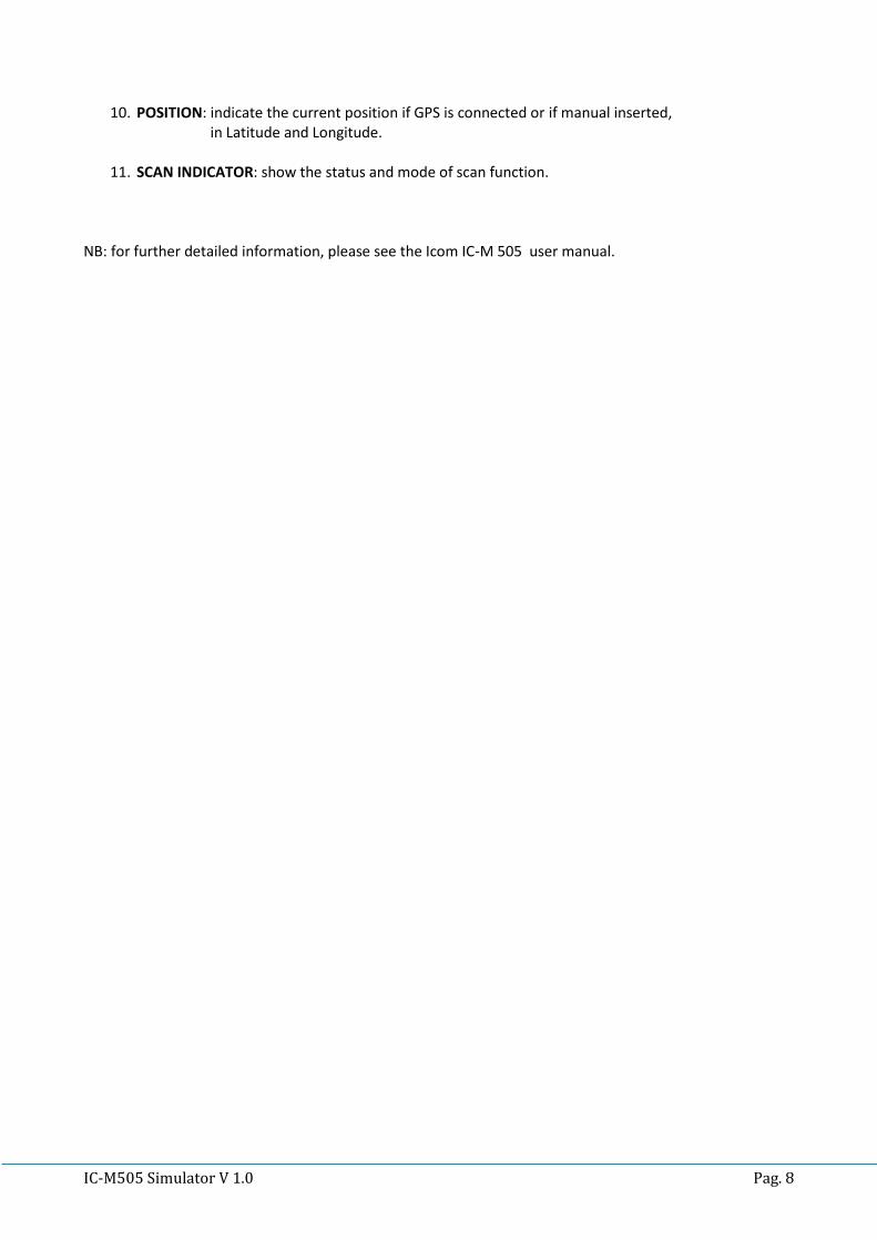
10. POSITION: indicate the current position if GPS is connected or if manual inserted, in Latitude and Longitude.
11. SCAN INDICATOR: show the status and mode of scan function.
NB: for further detailed information, please see the Icom IC-M 505 user manual.

IC-M505 Simulator V 1.0 Pag. 9
DSC CALLING PROCEDURES
DSC DISTRESS ALERT / SIMPLE PROCEDURE A distress call should be transmitted if, in the opinion of the Master, the ship or a person is in distress and requires immediate assistance. A distress call should include the ship’s position and time of validity. They are included automatically when a GPS receiver is connected. If no GPS is connected and situation permit, input manually your position and time of validity.
1. Lift the red DISTRESS switch cover, then press and hold the [DISTRESS] key.
The DISTRESS menu will appear on the LCD. The backlight of the LCD flashes while the radio display
is counting down.
2. The IC-M 505 watches for an DSC acknowledgment call on CH-70 or a voice call on CH-16 from a
coast station or another vessel.
3. When a distress DSC ACK is received on CH-70, a DSC DISTRESS alarm sounds and CH-16 will be
automatically selected. The LCD shows the MMSI of the station responding to your distress.
4. If no DSC ACK is received, the Distress alert will be repeated at approximately 4 minute intervals
until a DSC ACK is received.
5. To cancel the DSC Distress alarm signal from the speaker, press the CLR key.
6. Best practice: after DSC Distress call is transmitted on CH-70, wait 30 second then select CH-16 and
transmit a voice DISTRESS CALL and DISTRESS MESSAGE.
7. If a DSC ACK is received on CH-70 or a station respond to your distress call on CH-16, pick up the
microphone, press the PTT button and advise your distress situation.

IC-M505 Simulator V 1.0 Pag. 10
DSC DISTRESS ALERT WITH NATURE OF DISTRESS The IC-M 505 simulator is capable of transmitting a DSC Distress Alert with the following “Nature of Distress” categories:
UNDESIGNATED, FIRE, FLOODING, COLLISION, GROUNDING, CAPSIZING, SINKING, ADRIFT, ABANDONING, PIRACY, MOB
1. Press the [MENU] key. The <DSC MENU> will appear.
2. Rotate [CHANNEL] to select <DISTRESS SETTING> and then push [CHANNEL.ENTER].
3. The <DISTRESS> menu will appear on the LCD.
4. Rotate the [CHANNEL] to select the desired nature of distress category, then press the
[CHANNEL.ENTER].
5. Regardless of a GPS receiver connection, the current position / time information appear.
6. If it's not necessary to input or modify the information, push [CHANNEL.ENTER] or [16/C] several
time to skip the data input steps.
7. The position information appears. Set your position (lat and long) by rotating the [CHANNEL].
8. Push [CLR] one sec. to clear the position and UTC time data.
9. Push [CLR] to cancel and return to the DSC Menu.
10. Press and hold the [DISTRESS] key until a Distress Alert is transmitted.
11. After 2 sec. the transceiver will be set to CH-16 automatically.
12. Perform steps 2 to 7 of the basic operation described on previous section.

IC-M505 Simulator V 1.0 Pag. 11
CANCELLING A DSC DISTRESS ALERT
After a DSC DISTRESS CALL is transmitted, it is repeated every 4 minutes until the call is cancelled by the
user or until the radio is turned OFF and ON again.
The IC-M 505 has the capability to transmit a DSC DISTRESS CANCEL call by pressing the [CLR].
A DSC Distress Cancel will be transmitted on CH-70 then the transceiver will be set to CH-16
automatically and normal operation will be resumed.

IC-M505 Simulator V 1.0 Pag. 12
RECEIVING A DSC DISTRESS ALERT
1. When a DSC Distress Alert is received, an emergency alarm sounds and the transceiver will be set
to CH-16 automatically.
2. The display will show the MMSI of the vessel transmitting the distress.
3. Push the [CLR] key to stop the alarm sound.
4. Push the [CLR] key again to return to normal radio operation.

IC-M505 Simulator V 1.0 Pag. 13
ALL SHIPS CALL
The ALL SHIPS CALL functions allow contact to be established with other vessels and coast stations without
knowing their own MMSI ID. Also, priority for the call can be designated as “URGENCY” or “SAFETY”.
URGENCY CALL
o This type of call is used when a vessel may not truly be in distress, but has a potential
problem that may lead to a distress situation. This DSC call is usually followed by an
Urgency call on CH-16 using radio-telephony ( PAN PAN ).
SAFETY CALL
o This type of call is used to transmit important navigational or meteorological information to
other vessels. This DSC call is usually followed by a Safety call on CH-16 using radio-
telephony (SECURITE ).
1. Press the [MENU] key. The <DSC MENU> will appear.
2. Rotate [CHANNEL] to select <ALL SHIPS CALL> then push [CHANNEL.ENTER].
3. Rotate [CHANNEL] to select the desired category then push [CHANNEL.ENTER].
4. Push [CHANNEL.ENTER] to transmit the DSC call on CH-70.
5. After the All Ship Call has been transmitted, the screen will indicate the TX is completed.
6. Push [CLR] or wait 2 second to return to normal radio operation.
7. The transceiver will be set to CH-16 automatically.

IC-M505 Simulator V 1.0 Pag. 14
RECEIVING AN ALL SHIP CALL
1. When a DSC All Ship Call is received, an emergency alarm sounds.
2. The display will show the MMSI of the vessel or coast station transmitting the All Ship Call.
3. Push the [CLR] key to stop the alarm sound.
4. Push the [CHANNEL.ENTER] to monitor the channel for an announcement from the calling station.
5. Push the [CLR] key to ignore the call.

IC-M505 Simulator V 1.0 Pag. 15
INDIVIDUAL CALL
This feature allows the user to contact another vessel or coast station with a DSC VHF radio and
automatically switch the receiving radio to a desired communication channel and ring like a telephone.
INDIVIDUAL CALL – Manual MMSI entry
1. Press the [MENU] key. The <DSC MENU> will appear.
2. Rotate [CHANNEL] to select <INDIVIDUAL CALL> then push [CHANNEL.ENTER].
3. The transceiver will show the <INDIVIDUAL CALL> menu.
4. Rotate [CHANNEL] to select <MANUAL INPUT> then push [CHANNEL.ENTER].
5. Set the 9 digit MMSI number for the individual you wish to call by rotating the [CHANNEL].
6. When a digit is set, push [CHANNEL.ENTER] to move to move to the next digit to be entered.
7. Repeat the procedure until all nine space of the MMSI number which you want to contact are
entered.
8. If a mistake was made entering the MMSI number, repeat pressing the [DIAL] or [16/C] until the
wrong number is selected and then rotate [CHANNEL] to correct the entry.
9. When all 9 MMSI digits are entered push the [CHANNEL.ENTER].
10. Rotate [CHANNEL] to select a desired channel, then push the [CHANNEL.ENTER].
11. The <Individual Call Ready> menu appear.
12. Push the [CHANNEL.ENTER] to transmit the individual call.
13. After the Individual Call is transmitted, if a reply signal is not received, <WAITING FOR ACK> is
shown on the display which means that the IC-M505 is waiting for the station you called to send an
acknowledgment.
14. Push the [CLR] key to ignore the waiting for acknowledgement and return to normal operation.
15. When the IC-M505 receives an <ABLE TO COMPLY> acknowledgment from the station you called,
the radio will automatically switch to the operating channel selected in step 10 and produce a
ringing sound.
16. Press the microphone PTT button and call the other station you desire to communicate with.
17. Push the [CLR] key to revert to normal operation mode.

IC-M505 Simulator V 1.0 Pag. 16

IC-M505 Simulator V 1.0 Pag. 17
INDIVIDUAL CALL – Using Individual Call Directory
This feature allows the user to contact another vessel or coast station with a DSC VHF radio and
automatically switch the receiving radio to a desired communication channel and ring like a telephone.
The desired party station MMSI ID can be selected from a stored Call Directory instead of manually insert
the desired MMSI ID.
1. Press the [MENU] key. The <DSC MENU> will appear.
2. Rotate [CHANNEL] to select <INDIVIDUAL CALL> then push [CHANNEL.ENTER].
3. The transceiver will show the <INDIVIDUAL CALL> menu.
4. Rotate [CHANNEL] to select the pre-programmed individual address then push [CHANNEL.ENTER].
5. Rotate [CHANNEL] to select a desired channel, then push the [CHANNEL.ENTER].
6. The <Individual Call Ready> menu appear.
7. Push the [CHANNEL.ENTER] to transmit the individual call.

IC-M505 Simulator V 1.0 Pag. 18
RECEIVING AN INDIVIDUAL CALL
When receiving an Individual Call, you can transmit an acknowledgement (<Able to Comply> or
<Unable to Comply>) to the calling station using the on screen prompts .
1. When a DSC Individual call is received, a ringing alarm sounds.
2. The display will show the MMSI or name of the vessel transmitting the Individual Call.
3. Push [CLR] button once to stop the ringing alarm.
4. Push [CLR] button again to ignore the individual call and to revert to normal operation.
5. Push [CHANNEL.ENTER] to accept the individual call.
6. Select <ABLE TO COMPLY> or <UNABLE TO COMPLY> by rotating [CHANNEL] then press
[CHANNEL.ENTER] to confirm the selection.
7. The <Individual Ack Ready> menu appear.
8. Push [CHANNEL.ENTER] to transmit the individual acknowledgement.
9. When you transmit an <ABLE TO COMPLY> acknowledgment to the party station, the radio will
automatically switch to the received operating channel.

IC-M505 Simulator V 1.0 Pag. 19
GROUP CALL
This feature allows the user to contact a group of specific vessels (example: members of yacht club) or
coast stations with a group MMSI number using the group call function and to automatically switch to a
desired channel for voice communications.
This function is very useful for yachts club and vessels traveling together that want to make collectively
announcements on a predetermined channel.
Note: usually a GROUP MMSI is not provided by the national or government authority and must be inserted
by each group member following a best practice recommended by international rules:
First digit must be always a zero.
Next 3 digits must follow the nation’s assigned Maritime Identification Digit (MID).
Following 5 digit may be set as desired but different from any other group in the region.
GROUP CALL – Manual GROUP MMSI entry
1. Push [MENU] key. The <DSC MENU> will appear.
2. Rotate [CHANNEL] to select <GROUP CALL> then push [CHANNEL.ENTER].
3. The transceiver will show the <GROUP CALL> menu.
4. Rotate [CHANNEL] to select <MANUAL INPUT> then push [CHANNEL.ENTER].
5. The first digit is always a fixed “0” indicating that it will be a group MMSI number.
6. Set the other 8 digit MMSI number for the group you wish to call by rotating the [CHANNEL].
7. When a digit is set, push [CHANNEL.ENTER] to move to move to the next digit to be entered.
8. Repeat the procedure until all eight space of the MMSI number which you want to contact are
entered.
9. If a mistake was made entering the MMSI number, repeat pressing the [DIAL] or [16/C] until the
wrong number is selected and then rotate [CHANNEL] to correct the entry.
10. When all 8 digits are entered push the [CHANNEL.ENTER].
11. Rotate [CHANNEL] to select a desired channel, then push the [CHANNEL.ENTER].
12. The <Group Call Ready> menu appear.
13. Push the [CHANNEL.ENTER] to transmit the group call.
14. After the Group Call is transmitted, the radio will automatically switch to the operating channel
selected in step 11.
15. Listen to the channel to make sure it is not busy, then press the microphone PTT button and
transmit the message to the group of stations you desire to communicate with.
16. Push the [CLR] key to revert to normal operation mode.

IC-M505 Simulator V 1.0 Pag. 20

IC-M505 Simulator V 1.0 Pag. 21
GROUP CALL – Using Group Call Directory
This feature allows the user to contact a group of vessels or coast stations. The desired GROUP MMSI ID
can be selected from a stored Call Directory instead of manually insert the desired GROUP MMSI ID.
1. Push [MENU] key. The <DSC MENU> will appear.
2. Rotate [CHANNEL] to select <GROUP CALL> then push [CHANNEL.ENTER].
3. The transceiver will show the <GROUP CALL> menu.
4. Rotate [CHANNEL] to select the pre-programmed group address then push [CHANNEL.ENTER].
5. Perform steps 11 to 16 described on previous section to call the desired group.
RECEIVING A GROUP CALL
1. When a DSC Group call is received, a ringing alarm sounds.
2. The display will show the MMSI or name of the vessel transmitting the Group Call.
3. Push [CLR] to stop the ringing sound.
4. Push [CLR] button again to ignore the group call and to revert to normal operation.
5. Push [CHANNEL.ENTER] to accept the group call.
6. Monitor the channel for the station calling the group for a message.
7. If you want to respond, monitor the channel to make sure it is clear, then press the
microphone PTT button and talk to the calling station.

IC-M505 Simulator V 1.0 Pag. 22
POSITION REQUEST CALL
This feature allows the user to poll the location of another vessel and show the position of that vessel on
the LCD display. This is a great feature for anyone wanting to know the precise position of another vessel,
for example a friend’s boat you are cruising with.
Note: the other vessel must be equipped with an operating GPS receiver connected to an adequate DSC
transceiver and must not have set the transceiver to deny position request!
POSITION REQUEST – Manual MMSI entry
1. Push [MENU] key. The <DSC MENU> will appear.
2. Rotate [CHANNEL] to select <POSITION REQUEST> then push [CHANNEL.ENTER].
3. Rotate [CHANNEL] to select <MANUAL INPUT> then push [CHANNEL.ENTER].
4. Set the 9 digit MMSI number for the vessel you wish to call by rotating the [CHANNEL].
5. When a digit is set, push [CHANNEL.ENTER] to move to move to the next digit to be entered.
6. Repeat the procedure until all 9 space of the MMSI number which you want to contact are entered.
7. If a mistake was made entering the MMSI number, repeat pressing the [DIAL] or [16/C] until the
wrong number is selected and then rotate [CHANNEL] to correct the entry.
8. When all 9 digits are entered push the [CHANNEL.ENTER].
9. The <Pos Request Ready> menu appear.
10. Push the [CHANNEL.ENTER] to transmit the position request.
11. After the position request call has been transmitted, the radio wait for the acknowledgement from
the other station.
12. Push the [CLR] key to revert to normal operation mode.

IC-M505 Simulator V 1.0 Pag. 23
POSITION REQUEST – Using Individual Call Directory
1. Push [MENU] key. The <DSC MENU> will appear.
2. Rotate [CHANNEL] to select <POSITION REQUEST> then push [CHANNEL.ENTER].
3. Rotate [CHANNEL] to select the pre-programmed station address then push [CHANNEL.ENTER].
4. Perform steps 9 to 12 described on previous section to call the desired station.

IC-M505 Simulator V 1.0 Pag. 24
RECEIVING A POSITION REQUEST CALL
1. When a DSC Position Request call is received, a ringing alarm sounds.
2. The display will show the MMSI or name of the requesting vessel.
3. Push [CLR] to stop the ringing sound.
4. Push [CLR] button again to ignore the position request call and to revert to normal operation.
5. Push [CHANNEL.ENTER] to accept the position request call and to reply your position.

IC-M505 Simulator V 1.0 Pag. 25
POSITION REPORT CALL
This feature is similar to the position request feature, however instead of requesting a position of another
vessel this function allows you to send your position to another vessel. In order to send your position it’s
necessary to have a GPS receiver connected or to have manually input your position.
POSITION REPORT – Manual MMSI entry
1. Push [MENU] key. The <DSC MENU> will appear.
2. Rotate [CHANNEL] to select <POSITION REPORT> then push [CHANNEL.ENTER].
3. Rotate [CHANNEL] to select <MANUAL INPUT> then push [CHANNEL.ENTER].
4. Set the 9 digit MMSI number for the vessel you wish to call by rotating the [CHANNEL].
5. When a digit is set, push [CHANNEL.ENTER] to move to move to the next digit to be entered.
6. Repeat the procedure until all 9 space of the MMSI number which you want to contact are entered.
7. If a mistake was made entering the MMSI number, repeat pressing the [DIAL] or [16/C] until the
wrong number is selected and then rotate [CHANNEL] to correct the entry.
8. When all 9 digits are entered push the [CHANNEL.ENTER].
9. Regardless of a GPS receiver connection, the current position / time information appear.
10. If it's not necessary to input or modify the information, push [CHANNEL.ENTER] or [16/C] several
time to skip the data input steps.
11. Push [DIAL] or [16/C] several time to move between each position’s digit you need to replace.
12. Rotate [CHANNEL] to edit N (North Latitude) or S (South Latitude) when cursor is on the N or S
position.
13. Rotate [CHANNEL] to edit W (West Longitude) or E (East Longitude) when cursor is on the W or E
position.
14. Push [CLR] for 1 second to clear latitude / longitude data.
15. After setting the position data push [CHANNEL.ENTER] to set the UTC time.
16. Push [DIAL] or [16/C] several time to move between each time digit you need to replace.
17. Push [CLR] for 1 second to clear the UTC time data.
18. Set the current UTC time rotating [CHANNEL] then push [CHANNEL.ENTER].
19. The <Position Report Ready> menu appear.
20. Push the [CHANNEL.ENTER] to transmit the position report to the selected station.
21. Push the [CLR] key to revert to normal operation mode.

IC-M505 Simulator V 1.0 Pag. 26

IC-M505 Simulator V 1.0 Pag. 27
POSITION REPORT – Using Individual Call Directory
1. Push [MENU] key. The <DSC MENU> will appear.
2. Rotate [CHANNEL] to select <POSITION REPORT> then push [CHANNEL.ENTER].
3. Rotate [CHANNEL] to select the pre-programmed station address then push [CHANNEL.ENTER].
4. Perform steps 9 to 21 described on previous section to transmit your position to desired station.
RECEIVING A POSITION REPORT CALL
1. When a DSC Position Report call is received, a ringing alarm sounds.
2. The display will show the MMSI or name of the report vessel.
3. Push [CLR] to stop the ringing sound.
4. Push [CLR] again to ignore the position report call and to revert to normal operation.
5. Push [CHANNEL.ENTER] to show the position report call data of the other vessel.
6. Push [CLR] to resume normal operation.

IC-M505 Simulator V 1.0 Pag. 28
POLLING CALL
The IC-M505 has the capability of DSC POLLING REQUEST.
POLLING REQUEST – Manual MMSI entry
1. Push [MENU] key. The <DSC MENU> will appear.
2. Rotate [CHANNEL] to select <POLLING REQUEST> then push [CHANNEL.ENTER].
3. Rotate [CHANNEL] to select <MANUAL INPUT> then push [CHANNEL.ENTER].
4. Set the 9 digit MMSI number for the vessel you wish to call by rotating the [CHANNEL].
5. When a digit is set, push [CHANNEL.ENTER] to move to move to the next digit to be entered.
6. Repeat the procedure until all 9 space of the MMSI number which you want to contact are entered.
7. If a mistake was made entering the MMSI number, repeat pressing the [DIAL] or [16/C] until the
wrong number is selected and then rotate [CHANNEL] to correct the entry.
8. When all 9 digits are entered push the [CHANNEL.ENTER].
9. The <Polling Request Ready> menu appear.
10. Push the [CHANNEL.ENTER] to transmit the polling request.
11. After the polling request call has been transmitted, the radio wait for the acknowledgement from
the other station.
12. Push the [CLR] key to revert to normal operation mode.

IC-M505 Simulator V 1.0 Pag. 29
POLLING – Using Individual Call Directory
1. Push [MENU] key. The <DSC MENU> will appear.
2. Rotate [CHANNEL] to select <POLLING REQUEST> then push [CHANNEL.ENTER].
3. Rotate [CHANNEL] to select the pre-programmed station address then push [CHANNEL.ENTER].
4. Perform steps 9 to 21 described on previous section to transmit polling request to desired station.

IC-M505 Simulator V 1.0 Pag. 30
RECEIVING A POLLING CALL
1. When a DSC Polling Request call is received, a ringing alarm sounds.
2. The display will show the MMSI or name of the requesting vessel.
3. Push [CLR] to stop the ringing sound.
4. Push [CLR] again to ignore the polling report call and to revert to normal operation.
5. Push [CHANNEL.ENTER] to accept the polling request call and to reply to the other vessel.
6. Push [CLR] to resume normal operation.

IC-M505 Simulator V 1.0 Pag. 31
MANUAL POSITION AND TIME PROGRAMMING
You may send the Latitude/Longitude of your vessel manually when a GPS receiver is not connected or is
not functioning. After a position is entered, transmitting a DSC Distress or position report will contain the
manually entered position.
1. Push [MENU] key. The <DSC MENU> will appear.
2. Rotate [CHANNEL] to select <POSITION INPUT> then push [CHANNEL.ENTER].
3. Regardless of a GPS receiver connection, the current position / time information appears.
4. Set your position by rotating [CHANNEL] and push [CHANNEL.ENTER] to move to next digit.
5. If it's not necessary to input or modify the information, push [CHANNEL.ENTER] or [16/C] several
time to skip the data input steps.
6. Push [DIAL] or [16/C] several time to move cursor backward or forward, respectively.
7. Rotate [CHANNEL] to edit N (North Latitude) or S (South Latitude) when cursor is on the N or S
position.
8. Rotate [CHANNEL] to edit W (West Longitude) or E (East Longitude) when cursor is on the W or E
position.
9. Push [CLR] for 1 second to clear latitude / longitude data.
10. After setting the position data push [CHANNEL.ENTER] to set the UTC time.
11. Push [DIAL] or [16/C] several time to move between each time digit you need to replace.
12. Push [CLR] for 1 second to clear the UTC time data.
13. Set the current UTC time rotating [CHANNEL] then push [CHANNEL.ENTER].

IC-M505 Simulator V 1.0 Pag. 32
RECEIVED MESSAGES
The IC-M505 automatically store up to 10 distress messages and 10 other messages as an assistance
to the vessel’s logbook.
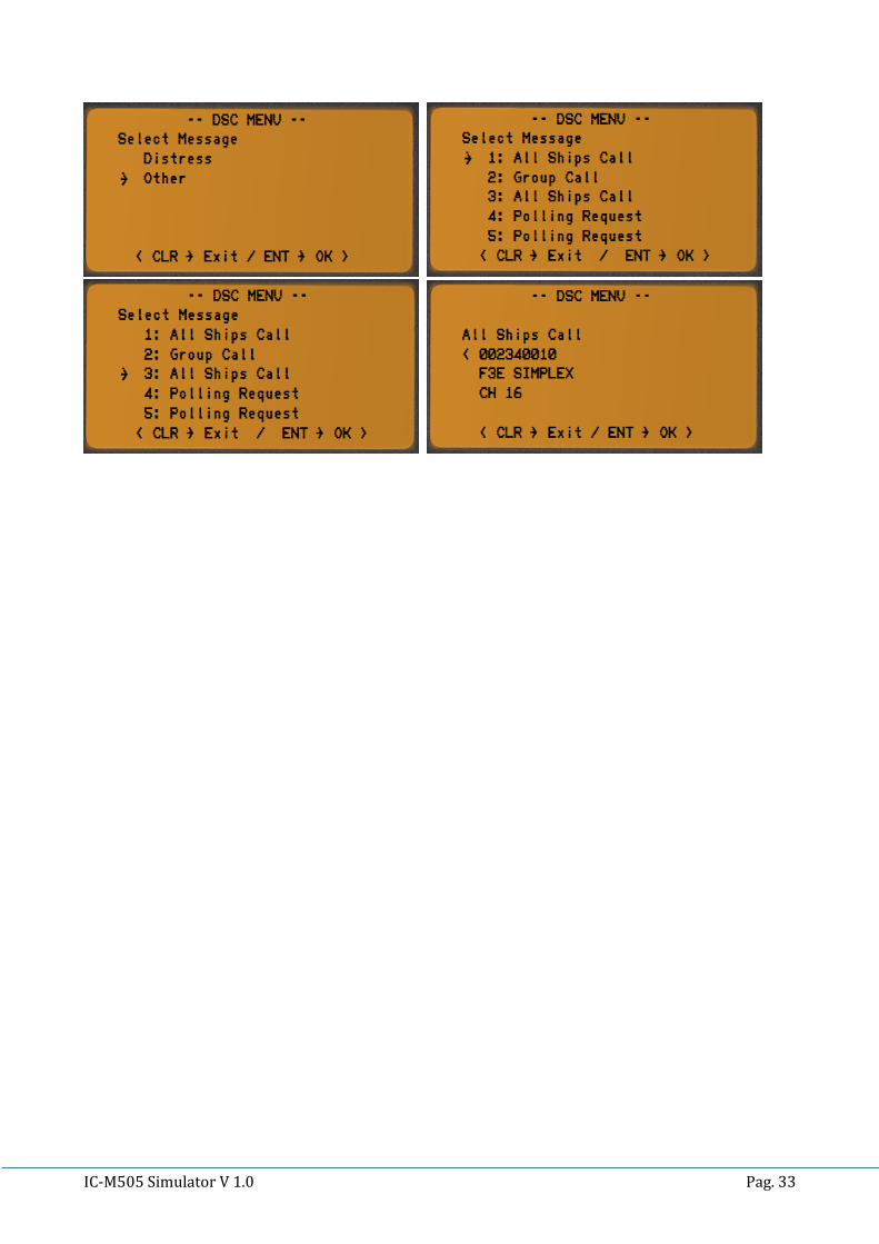
1. Push [MENU] key. The <DSC MENU> will appear.
2. Rotate [CHANNEL] to select <RECEIVED CALL> then push [CHANNEL.ENTER].
3. The <Select Message> menu appears.
4. Rotate [CHANNEL] to select desired message’s category and push [CHANNEL.ENTER].
5. Rotate [CHANNEL] to select desired message and push [CHANNEL.ENTER].
6. Rotate [CHANNEL] to scroll the entire message.
7. Push [CLR] to go back one step in to the menu.
8. Push [CHANNEL.ENTER] to revert the radio to normal operation.
IC-M505 Simulator V 1.0 Pag. 33

IC-M505 Simulator V 1.0 Pag. 34
VOICE CALLING PROCEDURES
DISTRESS CALL
1. Transmit a DSC Distress Alert, containing if possible the nature of distress and your position.
2. Wait briefly (30 sec) for a Distress Acknowledgment, usually from a CRS or MRCC.
3. Transmit a Distress Call, on CH-16 using voice radiotelephony.
4. Transmit a Distress Message, on CH-16 using voice radiotelephony.
Voice Distress Call:
Mayday ( 3x )
This is
Vessel Name ( 3x )
Vessel Call Sign
MMSI
Voice Distress Message:
Mayday
Vessel Name
Vessel Call Sign
MMSI
Last know position (LAT/LON) or relative to any geographical reference.
Time of validity of the position.
Nature of distress.
Requested help.
Other useful information that may help rescue operation.
OVER
Example:
MAYDAY MAYDAY MAYDAY
THIS IS
YACHT HOLIDAY HOLIDAY HOLIDAY
HBY5824 269235000
MAYDAY
YACHT HOLIDAY
HBY5824 269235000
POSITION 43 DEGREES 15 MINUTES NORTH
006 DEGREES 28 MINUTES EAST
AT 0845 UTC
THE SHIP IS SINKING
IMMEDIATE ASSISTANCE IS REQUIRED
THE SHIP IS A 46 FEET SAILING YACHT SLOOP DARK BLUE HULL
6 PERSONS ON BOARD
LAST COURSE 170 DEGREES SPEED FIVE KNOTS
OVER

IC-M505 Simulator V 1.0 Pag. 35
DISTRESS ACKNOWLEDGEMENT CALL
The international Radio Regulations RR state that usually a DSC Distress Acknowledgment shall be
transmitted only by a Coast station or by a MRCC.
If a vessel receive a DSC Distress Call and / or a voice Distress Call shall:
Listen on the distress channel for the Distress Traffic and take note of the content.
If after 5 minutes, no Distress Acknowledgment has been transmitted by a SRC or MRCC,
proceed with a Distress Acknowledgement using voice radiotelephony.
Try to contact a CRS or MRCC with any method to inform them about situation.
Voice Distress Acknowledgment:
MAYDAY
NAME OF THE DISTRESS VESSEL or;
MMSI or;
ANY OTHER DISTRESSED VESSEL IDENTIFICATION
THIS IS VESSEL NAME
CALL SIGN
MMSI
RECEIVED MAYDAY
Example:
MAYDAY
YACHT HOLIDAY
THIS IS YACHT LUCKY
HBY4247
269285000
RECEIVED MAYDAY

IC-M505 Simulator V 1.0 Pag. 36
DISTRESS CALL RELAY
Distress Call relay to a land station
This is only broadcasted when a station learns that:
Another vessel has transmitted a DSC Distress Call that is not confirmed by any station after 5 minutes; or
Another vessel is in Distress and is unable to transmit the Distress Alert itself, (example: direct visual observation) and in opinion of the master further help is required.
Usually the VHF DSC radio installed on pleasure or small vessels, can’t transmit a DSC Distress Alert Relay because the <Class D> DSC controller are not equipped with this function. The pleasure craft is then required to relay the distress call directly to a land station (CRS or MRCC) on an appropriate monitored working channel using Voice Radiotelephony.
MAYDAY RELAY (3x)
NAME OF CALLED STATION (3x)
THIS IS
VESSEL NAME (3x)
CALL SIGN
OVER
Example:
MAYDAY RELAY MAYDAY RELAY MAYDAY RELAY
BREMEN RESCUE BREMEN RESCUE BREMEN RESCUE
THIS IS
YACHT DOLPHIN DOLPHIN DOLPHIN HBY 3585
OVER
When Bremen Rescue answer the call and request to continue with the <Go Ahead>:
BREMEN RESCUE THIS IS SAILING YACHT DOLPHIN HBY 3585
POSITION 28 DEGREES 12 MINUTES NORTH 030 DEGREES 15 MINUTES EAST AT
0645 UTC
WE OBSERVED AN UNIDENTIFIED TRAWLER SINKING ABOUT 3 NAUTICAL MILES
SOUTHEAST OF OUR REPORTED POSITION WE ARE HEADING TO THE TRAWLER
WE REQUEST IMMEDIATE ADDITIONAL ASSISTANCE FROM ASHORE AND OTHER
SHIPS IN VICINITY
OVER

IC-M505 Simulator V 1.0 Pag. 37
Distress Call relay to All Stations
In case no land station (CRS or MRCC) can be directly contacted and alarmed, the master may
transmit a Distress Call Relay to All Stations using Voice Radiotelephony on CH-16.
MAYDAY RELAY (3x)
ALL STATIONS (3x)
THIS IS
VESSEL NAME (3x)
CALL SIGN
WE RECEIVED FOLLOWING DISTRESS MESSAGE
AT ….. UTC ON CHANNEL …..
OVER
Example:
MAYDAY RELAY MAYDAY RELAY MAYDAY RELAY
ALL STATIONS ALL STATIONS ALL STATIONS
THIS IS
YACHT DOLPHIN DOLPHIN DOLPHIN HBY3585
WE RECEIVED THE FOLLOWING DISTRESS MESSAGE AT 0700 UTC ON CHANNEL 16
MAYDAY YACHT HOLIDAY HBY5824 269235000
POSITION 43 DEGREES 15 MINUTES NORTH 006 DEGREES 28 MINUTES EAST
AT 0645 UTC
THE SHIP IS SINKING
IMMEDIATE ASSISTANCE IS REQUIRED
THE SHIP IS A 46 FEET SAILING YACHT SLOOP DARK BLUE HULL
6 PERSONS ON BOARD LAST COURSE 170 SPEED FIVE KNOTS
OVER

IC-M505 Simulator V 1.0 Pag. 38
CANCELLING A FALSE DISTRESS CALL
If a vessel transmit a false DSC Distress Call, this should be immediately cancelled !
If the <CANCEL> function is available on the radio, this should be used as soon as possible.
Power cycle the radio OFF and ON to stop the automatic alarm re-trasmission.
Transmit the Distress Cancel message on the CH-16.
Voice Distress Cancel Message:
ALL STATIONS (3x)
THIS IS
VESSEL NAME (3x)
CALL SIGN
MMSI
PLEASE CANCEL MY DISTRESS ALERT OF ……. UTC
OVER
Example:
ALL STATIONS ALL STATIONS ALL STATIONS
THIS IS
SAILING YACHT TROUBLE TROUBLE TROUBLE
HBY2854 269432000
PLEASE CANCEL MY DISTRESS ALERT OF 0700 UTC
OVER

IC-M505 Simulator V 1.0 Pag. 39
URGENCY CALL
There is no DSC Acknowledgment for a DSC Urgency Call transmitted to All SHIPS.
Transmit the Urgency Call and Message using Voice Radiotelephony on CH-16.
If CH-16 is being used for a Distress Traffic, the Urgency Call and Message must be delayed
until the Distress Traffic is over or must be addressed directly to a CRS or MRCC using a
working channel of the land station.
Voice Urgency Message:
PAN PAN (3x)
ALL STATIONS (3x)
THIS IS
VESSEL NAME (3x)
CALL SIGN
MMSI
LAST KNOW POSITION (LAT/LON) OR ANY GEOGRAPHICAL REFERENCE.
TIME OF VALIDITY OF THE POSITION.
URGENCY MESSAGE.
OVER
Example:
PAN PAN PAN PAN PAN PAN
ALL STATIONS ALL STATIONS ALL STATIONS
THIS IS
SAILING YACHT DOLPHIN DOLPHIN DOLPHIN
HBY2854 269432000
POSITION 43 DEGREES 15 MINUTES NORTH 006 DEGREES 28 MINUTES EAST
AT 0845 UTC
OUR RUDDER IS BROKEN AND WE ARE DRIFTING SLOWLY IN TO DANGER
WE NEED TOWING ASSISTANCE
OVER

IC-M505 Simulator V 1.0 Pag. 40
CANCELLING AN URGENCY CALL
When an urgency announcement or call and message was transmitted to more than one station and action is no longer required, an urgency cancellation should be sent by the station responsible for its transmission, using voice radiotelephony.
Voice Urgency Cancel Message:
PAN PAN (3x)
ALL STATIONS (3x)
THIS IS
VESSEL NAME (3x)
CALL SIGN
MMSI
URGENCY CANCELLATION MESSAGE.
OVER
Example:
PAN PAN PAN PAN PAN PAN
ALL STATIONS ALL STATIONS ALL STATIONS
THIS IS
SAILING YACHT DOLPHIN DOLPHIN DOLPHIN
HBY2854 269432000
PLEASE CANCEL MY URGENCY MESSAGE OF 0725 UTC
OVER

IC-M505 Simulator V 1.0 Pag. 41
SAFETY CALL
There is no DSC Acknowledgment for a DSC Safety Call transmitted to All SHIPS.
Transmit the Safety Call and Message using Voice Radiotelephony on CH-16.
If CH-16 is being used for a Distress or Urgency Traffic, the Safety Call and Message must be
delayed until the Distress Traffic is over or must be addressed directly to a CRS or MRCC using
a working channel of the land station.
Voice Safety Message:
SECURITE (3x)
ALL STATIONS (3x)
THIS IS
VESSEL NAME (3x)
CALL SIGN
MMSI
LAST KNOW POSITION (LAT/LON) OR ANY GEOGRAPHICAL REFERENCE.
TIME OF VALIDITY OF THE POSITION.
SAFETY MESSAGE.
OVER
Example:
SECURITE SECURITE SECURITE
ALL STATIONS ALL STATIONS ALL STATIONS
THIS IS
SAILING YACHT DOLPHIN DOLPHIN DOLPHIN
HBY2854 269432000
3 NAUTICAL MILES SOUTH OF CAPE FANTASY
WE OBSERVED A DRIFTING YELLOW CONTAINER DANGEROUS FOR NAVIGATION
SHIPS IN VICINITY PLEASE NAVIGATE CAREFULLY
OVER
Source: Federal Office of Communications, UFCOM/BAKOM , Switzerland (www.bakom.admin.ch),
Not_Dringlichkeit_Sicherheit_i.pdf