ibs testing pocket guide: part 1 - inicio | megperú
TRANSCRIPT

1
IBS Testing Pocket Guide: Part 1

2
Table of Contents
Introduction ................................................................................ 3
IBS Overview ............................................................................... 4
Design Phase:............................................................................................... 4
Deployment Phase: ..................................................................................... 5
Operation Phase: ......................................................................................... 5
Types of DAS ................................................................................... 6
Different RF Design Approaches ...................................................... 9
RF Design Assumptions ................................................................................ 9
Under-Design ............................................................................ 11
Over-Design .............................................................................. 11
RF Design Verification and Optimization Tests ........................... 12
CW Transmitter Walk-Testing ........................................................ 14
Antenna Coverage and Overlap ..................................................... 18
copyright 2019, www.consutixwireless.com
Consultixwireless.com
57A, El-Teseen st., 11835, New Cairo, Egypt.
Tel: +20 (2) 25647370

IBS Testing Pocket Guide: Part 1 consultixwireless.com
3
Introduction
Test and Measurements play a vital role in enhancing IBS
site’s quality and optimizing implementation Cost, hence
helping businesses deliver reliable communication
infrastructure with profitability and short delivery time.
Test procedures span the complete lifecycle of IBS Projects.
From the moment the designer receives floor layouts of the
building, planning for design verification takes place.
Additionally, propagation model calibration and advanced
testing can also take part. By the time the site has been
implemented, commissioning and acceptance tests are
performed. And testing continues in the operation phase as
well.
To be able to understand the IBS testing requirements, a
fair understanding of different IBS technologies and how
they are implemented is required. In this guide we will
explore the typical IBS site lifecycle and the test setups
related to each phase of an In-Building site from design,
implementation to maintenance and operations. We will
also introduce some advanced test procedures for
performance optimization, coverage benchmarking,
troubleshooting and monitoring

IBS Testing Pocket Guide: Part 1 consultixwireless.com
4
IBS Overview
In-building Systems refers to a category of systems used to
deliver reliable coverage for indoor subscribers. That
includes Distributed Antenna Systems (DAS), Small-Cells
and BDA’s.
A typical IBS project will go through three major phases;
Design, Implementation, and finally Operation. The details
and milestones of each phase can vary from place to
another according to contractual differences and
depending on who performs the design or implements the
system.
Each of these phases has its own test and measurements
procedures serving a specific goal for the successful
delivery of the IBS system
Design Phase:
In the design phase the designer performs several tasks to
produce an implementable design that can deliver the
required KPI’s. Typically, a preliminary design will be
1 There are many approaches to redesign and achieve higher (or lower) signal levels
given the site is in the design phase. However, it might be the case where additional
signal power is required to be injected into the existing DAS site. At such extreme
created using RF design software followed (or preceded) by
RF surveys. For some complex RF environments, the
designer may perform advanced tests to optimize the
design before submitting it.
Design verification tests at this stage prevent costly
consequences of design errors and reduce unneeded
design margins that may -unnecessarily- increase the
project installation and operational cost.
To understand the importance of design margins, a well-
known rule of thumb is that an additional 3 dB in signal level
is in reality double the RF power. This can translate into
doubling of RF Signal sources in extreme cases 1. In reality
the addition (or reduction) of design margins will always
result in a considerable increase (or reduction) of RF
equipment and can influence the project delivery and
operations cost afterwards. Hence, RF Design verification is
very important to learn exactly how much design margin is
adequate above the required KPIs. Therefore, optimizing
cases the RF equipment will increase significantly with marginal increase of
coverage levels

IBS Testing Pocket Guide: Part 1 consultixwireless.com
5
the design and avoiding over-design or under-design
situations.
Deployment Phase:
IBS deployment covers all IBS system and subsystems
construction from structured cabling, electrical supply
system, air-conditioning and other related works.
Several RF measurement procedures are required during
this stage to test the quality of all RF and structured cabling
installations.
Following a predefined testing process helps streamlining
the project implementation and acceptance.
Operation Phase:
By the Time the site has been accepted, responsibility of its
performance is transferred to the Operations and
Maintenance teams. It can undergo periodic tests on the
live network RF signal or offline (where the system is taken
offline in maintenance time frame). The level of testing of
the infrastructure and service may vary during operational
phase depending on the importance of the Venue and
other commercial considerations. In general MNO tends to
prefer live network measurements that reflects end user
experience and then might conduct advanced
troubleshooting if a significant degradation is reported
Maintenance guidelines from DAS equipment
manufacturers should be followed which can vary from
vendor to another. A certain level of equipment availability
and status monitoring can be obtained by the active
equipment. More advanced RF availability reporting and
testing can be performed on the Antenna level using
distributed sensors.

IBS Testing Pocket Guide: Part 1 consultixwireless.com
6
Types of DAS
DAS can be classified into two major categories: Passive
DAS and Active DAS. Passive DAS system utilizes a dedicated
indoor Base Transceiver Station (BTS) to distribute its signal
to multiple indoor antennas using a passive distributing
network. Passive network is formed of Coaxial cables, equal
and non-equal power splitters. On the other hand, active
DAS system distributes the signal through amplification of
the signal electronically on the forward and reverse paths,
utilizing optical fiber, network cables and other types of
low-loss physical media to deliver better signal with the
target of achieving better quality of service. The
combination of active and passive DAS is often referred to
as Hybrid DAS which can be considered a third category.
Active DAS mainly solves three coverage problems that
legacy macro-cellular, dedicated indoor BTS and Femto-
cells cannot solve; 1) Indoor site with a low number of
subscribers but with a wide coverage area that requires
more power than what a typical dedicated BTS can provide.
2) A second example is the other extreme; a high number
Figure 1 DAS classification.

IBS Testing Pocket Guide: Part 1 consultixwireless.com
7
of subscribers in a relatively small coverage area with
limited space to host the required equipment for such high
concentration.
3) Finally when some Active DAS equipment comes with a
solution for a third problem where quick and easy
deployment is required due to physical limitations and
aesthetic considerations.
Figure 2 Passive DAS

IBS Testing Pocket Guide: Part 1 consultixwireless.com
8
Figure 3 Different RF design Approaches

IBS Testing Pocket Guide: Part 1 consultixwireless.com
9
Different RF Design Approaches
IBS RF designs can have a wide variation in terms of tools,
methods and details. RF design tools can be as simple as a
link-budget spreadsheet or an advanced RF simulator with
wall database and 3D models. Depending on designers
preferred approach, the one thing in common to all of these
approaches is the need to validate the design and perform
measurement. Table 1 provides a summary of what can go
wrong if designs deviate from optimum quantities.
Measurement-based design:
An approach where designs are made based on actual
coverage measurements. No RF coverage prediction is
involved in this process.
This approach reduces time consumed in drawing and
optimizing wall models and provides the highest confidence
in design, hence leaving no chance for prediction errors.
Extremely Detailed 3D wall model:
Requires a significant effort in detailing the model to reduce
errors of approximations. Such approach provides very
good prediction results given that wall types are carefully
selected to match the actual walls and also wall loss
parameters have to identical to the real material.
Software tools providers implement algorithms to calibrate
wall losses and propagation model parameter based on
field measurements.
In between these two design approaches is a full spectrum of possibilities where designs vary in wall details and RF verification details, nevertheless, an overall coverage measurement is the common factor for all design types. With more verification required for some designs based on the design assumptions.
RF Design Assumptions
Some assumptions must be verified with the proper Field
measurement to avoid potential failures. These
assumptions can also be viewed as sources of errors in RF
design, such as:
Walls:
Selection of wall types is a human decision that can be very
expensive if the wrong type was chosen. A lower loss
material may result in better coverage prediction than
actual. On the other hand, selecting a material of higher loss
than reality -which can be seen as a safer approach- will
always result in an IBS with better coverage than
predictions, however, it will be at the expense of higher

IBS Testing Pocket Guide: Part 1 consultixwireless.com
10
project cost and can also result in Performance
degradation.2
Even for correctly selected wall types, the actual wall loss
parameters may vary depending on Wall-finish.
Wall thickness as well may vary gradually in typical floors
between topmost and lowermost floors, for example, High-
rise buildings will have thicker columns on the lower floors
than higher ones
Such details are impractical to take into account when
building wall models for predictions. The best way to take
them into account is by adding a reasonable and validated
design margin.
Propagation model Empirical parameters
For computation speed optimization, deterministic
coverage prediction model such as Ray Tracing can have
some parameters that are rather empirical but not
deterministic. Empirical parameter values are based on
previous measurements of similar propagation
environments.
2 RF isolation between sectors influence soft hand-off regions and SINR values. For high density sites where multiple sectors exists, it is very important to have the proper wall losses to avoid RF interference between RF sectors
An RF designer should make sure such parameters are
applicable to the particular environment in question and do
not accept the default values without verification.
Waveguiding effect in tunnels is an example of such cases
where the coverage may vary significantly depending on
tunnel finish material, reflection and absorption
characteristics. CW testing is very important to verify the
coverage for car parks, trains, lift shafts, atriums and
inclined surfaces.
Antenna footprint and Coverage overlap is important to
verify for complex venues such as stadium to optimize the
design before implementation.

IBS Testing Pocket Guide: Part 1 consultixwireless.com
11
Table 1 Non-optimized design consequences
Under-Design
Over-Design
Site does not meet Coverage KPIs
Possible Contractual Penalties
Possibility to fail in Performance KPIs due to interference
Possible Contractual Penalties
Costly retrofitting of DAS. Specially for Passive Network
Unjustified project cost paid by Infrastructure owner. Higher
OPEX. More hardware → Higher energy bill
Unhealthy profit margins, if not operating at loss
Risk of losing a bid due to uncompetitive pricing
Damaging the service integrator Image
Damaging the service integrator Image (if unveiled).
Chances of spillage and challenges on Macro networks for
optimization.
Highrise tower spillage becomes a huge radiating element
causing higher pilot pollution.

IBS Testing Pocket Guide: Part 1 consultixwireless.com
12
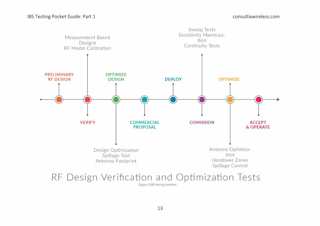
RF Design Verification and Optimization Tests
In this section of the guide, test procedures for the IBS will be explained in details. Figure 5 shows an overall testing summary aligned with the IBS project lifecycle. Throughout this section we will use the symbols in Figure 4 to refer to the test equipment utilized along the section.
Figure 4 Legend
IBS Testing Pocket Guide: Part 1 consultixwireless.com
13
Figure 5 IBS testing timeline

IBS Testing Pocket Guide: Part 1 consultixwireless.com
14
CW Transmitter Walk-Testing
Used For:
• Actual Coverage heat maps for measurement-based-
designs
• Propagation model calibration
• Wall losses calibration
• Overall coverage validation and comparison.
Tools Required:
• 1 x CW transmitter
• 1 x CW Receiver or Spectrum Analyzer
• Data recording/drawing software.
Procedure:
1. Setup and Measurement:
a. Analyze different propagation environments
of the building
b. Identify required setups and testing routes
c. Adjust the transmitter antenna height to
appropriate levels
d. Record All power settings, Jumper losses and
Antenna model
e. Perform walk testing with a receiver or
spectrum analyzer.
2. Post processing
a. Export data into simulation tools
b. Perform model calibration as per your SW tool
instructions.
c. Alternatively, export Walk-test heatmaps on
floor layouts for visual results and comparison
with predictions.
Details When performing CW testing for design verification, designers can have multiple options depending on the way they intend to use the test results:
1. For Measurement Based Designs and overall verification (Figure 6)
a. Preliminary Design should be done prior to CW to know the output EIRP of the design
b. To setup and perform CW with similar EIRP. c. To plot and compare to predictions
2. For Calibrating Propagation parameters (Figure 8) a. Designer is free to choose the output power
of the Antenna during the CW test b. Propagation model parameters can be
calculated using these values and the distance
c. Import to the prediction software and follow its calibration procedures.

IBS Testing Pocket Guide: Part 1 consultixwireless.com
15
Figure 6 CW output power planning based on Design

IBS Testing Pocket Guide: Part 1 consultixwireless.com
16
Figure 7 CW for Coverage verification

IBS Testing Pocket Guide: Part 1 consultixwireless.com
17
Figure 8 CW for model calibration

IBS Testing Pocket Guide: Part 1 consultixwireless.com
18
Antenna Coverage and Overlap
Used For:
Optimizing the Design either before or after
implementation to gain more information on:
• Handover zones
• Sector Overlap
Important for stadiums and open propagation areas where
sector overlap is required to be minimized.
Procedure:
Single antenna foot print requires a single transmitter.
Handover zones require two test transmitters or a multi-
port transmitter (depending on the antenna separation).
Two different CW frequencies are injected into adjacent
sectors’ antennas.
Walk test recording and plotting of both signals to be
compared and post processed for handover zone
calculations.
The area to be scanned by the walk-test depends on the
Application. And this is expected to be larger for
measurement-based designs


IBS Testing Pocket Guide: Part 1 consultixwireless.com
20
Graphics:Vector Open Stock
www.vectoropenstock.com