ibm mq v8 features and enhancements · chapter 7. smf changes: channel ... chapter 13. scm...
TRANSCRIPT

ibm.com/redbooks
Front cover
IBM MQ V8 Features and Enhancements
Rufus CredleCarolyn T Elkins
Peter HaywardValerie LampkinMatthew Leming
Jonatan Maya SanchezMark TaylorMark Wilson
Discover new features that bring value to your business
Learn from scenarios with sample configurations
Maximize your investment in IBM MQ


International Technical Support Organization
IBM MQ V8 Features and Enhancements
October 2014
SG24-8218-00

© Copyright International Business Machines Corporation 2014. All rights reserved.Note to U.S. Government Users Restricted Rights -- Use, duplication or disclosure restricted by GSA ADP ScheduleContract with IBM Corp.
First Edition (October 2014)
This edition applies to IBM MQ Version 8.
Note: Before using this information and the product it supports, read the information in “Notices” on page ix.

Contents
Notices . . . . . . . . . . . . . . . . . . . . . . . . . . . . . . . . . . . . . . . . . . . . . . . . . . . . . . . . . . . . . . . . . ixTrademarks . . . . . . . . . . . . . . . . . . . . . . . . . . . . . . . . . . . . . . . . . . . . . . . . . . . . . . . . . . . . . . .x
Preface . . . . . . . . . . . . . . . . . . . . . . . . . . . . . . . . . . . . . . . . . . . . . . . . . . . . . . . . . . . . . . . . . xiAuthors. . . . . . . . . . . . . . . . . . . . . . . . . . . . . . . . . . . . . . . . . . . . . . . . . . . . . . . . . . . . . . . . . . xiiNow you can become a published author, too! . . . . . . . . . . . . . . . . . . . . . . . . . . . . . . . . . . xivComments welcome. . . . . . . . . . . . . . . . . . . . . . . . . . . . . . . . . . . . . . . . . . . . . . . . . . . . . . . xivStay connected to IBM Redbooks . . . . . . . . . . . . . . . . . . . . . . . . . . . . . . . . . . . . . . . . . . . . .xv
Part 1. Introducing IBM MQ V8 and new features . . . . . . . . . . . . . . . . . . . . . . . . . . . . . . . . . . . . . . . . . . . 1
Chapter 1. Introduction. . . . . . . . . . . . . . . . . . . . . . . . . . . . . . . . . . . . . . . . . . . . . . . . . . . . 31.1 What is IBM MQ . . . . . . . . . . . . . . . . . . . . . . . . . . . . . . . . . . . . . . . . . . . . . . . . . . . . . . . 4
1.1.1 Product release timeline . . . . . . . . . . . . . . . . . . . . . . . . . . . . . . . . . . . . . . . . . . . . . 51.2 What is new in IBM MQ V8 . . . . . . . . . . . . . . . . . . . . . . . . . . . . . . . . . . . . . . . . . . . . . . . 6
1.2.1 Security . . . . . . . . . . . . . . . . . . . . . . . . . . . . . . . . . . . . . . . . . . . . . . . . . . . . . . . . . . 61.2.2 Performance and scalability . . . . . . . . . . . . . . . . . . . . . . . . . . . . . . . . . . . . . . . . . . 71.2.3 System z exploitation . . . . . . . . . . . . . . . . . . . . . . . . . . . . . . . . . . . . . . . . . . . . . . . 81.2.4 Cross-product consistency . . . . . . . . . . . . . . . . . . . . . . . . . . . . . . . . . . . . . . . . . . 101.2.5 Usability . . . . . . . . . . . . . . . . . . . . . . . . . . . . . . . . . . . . . . . . . . . . . . . . . . . . . . . . 101.2.6 Platforms: 64-bit and 32-bit . . . . . . . . . . . . . . . . . . . . . . . . . . . . . . . . . . . . . . . . . . 121.2.7 Standards and APIs . . . . . . . . . . . . . . . . . . . . . . . . . . . . . . . . . . . . . . . . . . . . . . . 12
1.3 Supported environments . . . . . . . . . . . . . . . . . . . . . . . . . . . . . . . . . . . . . . . . . . . . . . . . 13
Chapter 2. Topic host routed publish/subscribe . . . . . . . . . . . . . . . . . . . . . . . . . . . . . . 152.1 Introduction . . . . . . . . . . . . . . . . . . . . . . . . . . . . . . . . . . . . . . . . . . . . . . . . . . . . . . . . . . 16
2.1.1 The example case. . . . . . . . . . . . . . . . . . . . . . . . . . . . . . . . . . . . . . . . . . . . . . . . . 172.1.2 Terminology . . . . . . . . . . . . . . . . . . . . . . . . . . . . . . . . . . . . . . . . . . . . . . . . . . . . . 18
2.2 Distributed publish/subscribe topologies. . . . . . . . . . . . . . . . . . . . . . . . . . . . . . . . . . . . 192.2.1 Proxy subscriptions. . . . . . . . . . . . . . . . . . . . . . . . . . . . . . . . . . . . . . . . . . . . . . . . 212.2.2 Hierarchies . . . . . . . . . . . . . . . . . . . . . . . . . . . . . . . . . . . . . . . . . . . . . . . . . . . . . . 222.2.3 Clusters. . . . . . . . . . . . . . . . . . . . . . . . . . . . . . . . . . . . . . . . . . . . . . . . . . . . . . . . . 222.2.4 Direct routed clustered topics . . . . . . . . . . . . . . . . . . . . . . . . . . . . . . . . . . . . . . . . 232.2.5 Topic host routed clustered topics . . . . . . . . . . . . . . . . . . . . . . . . . . . . . . . . . . . . 25
2.3 Comparison of topologies . . . . . . . . . . . . . . . . . . . . . . . . . . . . . . . . . . . . . . . . . . . . . . . 272.3.1 Scaling . . . . . . . . . . . . . . . . . . . . . . . . . . . . . . . . . . . . . . . . . . . . . . . . . . . . . . . . . 272.3.2 Availability . . . . . . . . . . . . . . . . . . . . . . . . . . . . . . . . . . . . . . . . . . . . . . . . . . . . . . . 282.3.3 Publication flows . . . . . . . . . . . . . . . . . . . . . . . . . . . . . . . . . . . . . . . . . . . . . . . . . . 282.3.4 Configuration. . . . . . . . . . . . . . . . . . . . . . . . . . . . . . . . . . . . . . . . . . . . . . . . . . . . . 282.3.5 Comparison summary. . . . . . . . . . . . . . . . . . . . . . . . . . . . . . . . . . . . . . . . . . . . . . 29
2.4 Performance tips . . . . . . . . . . . . . . . . . . . . . . . . . . . . . . . . . . . . . . . . . . . . . . . . . . . . . . 292.5 Problem determination . . . . . . . . . . . . . . . . . . . . . . . . . . . . . . . . . . . . . . . . . . . . . . . . . 30
Chapter 3. User authentication . . . . . . . . . . . . . . . . . . . . . . . . . . . . . . . . . . . . . . . . . . . . 333.1 Introduction to authentication . . . . . . . . . . . . . . . . . . . . . . . . . . . . . . . . . . . . . . . . . . . . 34
3.1.1 IBM MQ history . . . . . . . . . . . . . . . . . . . . . . . . . . . . . . . . . . . . . . . . . . . . . . . . . . . 343.2 Identity repositories . . . . . . . . . . . . . . . . . . . . . . . . . . . . . . . . . . . . . . . . . . . . . . . . . . . . 343.3 Relationship to authorization. . . . . . . . . . . . . . . . . . . . . . . . . . . . . . . . . . . . . . . . . . . . . 35
© Copyright IBM Corp. 2014. All rights reserved. iii

3.4 Administration for authentication. . . . . . . . . . . . . . . . . . . . . . . . . . . . . . . . . . . . . . . . . . 353.4.1 AUTHINFO objects . . . . . . . . . . . . . . . . . . . . . . . . . . . . . . . . . . . . . . . . . . . . . . . . 353.4.2 Simple example . . . . . . . . . . . . . . . . . . . . . . . . . . . . . . . . . . . . . . . . . . . . . . . . . . 39
3.5 Application programming for authentication . . . . . . . . . . . . . . . . . . . . . . . . . . . . . . . . . 393.5.1 MQI . . . . . . . . . . . . . . . . . . . . . . . . . . . . . . . . . . . . . . . . . . . . . . . . . . . . . . . . . . . . 39
3.6 JMS and XMS . . . . . . . . . . . . . . . . . . . . . . . . . . . . . . . . . . . . . . . . . . . . . . . . . . . . . . . . 403.7 XA Transaction managers. . . . . . . . . . . . . . . . . . . . . . . . . . . . . . . . . . . . . . . . . . . . . . . 413.8 Relationship to CHLAUTH rules . . . . . . . . . . . . . . . . . . . . . . . . . . . . . . . . . . . . . . . . . . 413.9 Using the mqccred channel security exit. . . . . . . . . . . . . . . . . . . . . . . . . . . . . . . . . . . . 413.10 Password protection on the network . . . . . . . . . . . . . . . . . . . . . . . . . . . . . . . . . . . . . . 433.11 Using authentication in programs provided by MQ . . . . . . . . . . . . . . . . . . . . . . . . . . . 433.12 Solving authentication failures . . . . . . . . . . . . . . . . . . . . . . . . . . . . . . . . . . . . . . . . . . 443.13 Summary. . . . . . . . . . . . . . . . . . . . . . . . . . . . . . . . . . . . . . . . . . . . . . . . . . . . . . . . . . . 46
Chapter 4. TLS/SSL Digital Certificate Management . . . . . . . . . . . . . . . . . . . . . . . . . . . 474.1 Basic security concepts. . . . . . . . . . . . . . . . . . . . . . . . . . . . . . . . . . . . . . . . . . . . . . . . . 484.2 Multiple certificates and names for digital certificates . . . . . . . . . . . . . . . . . . . . . . . . . . 504.3 The CERTLABL parameter . . . . . . . . . . . . . . . . . . . . . . . . . . . . . . . . . . . . . . . . . . . . . . 514.4 Using SSLCERTI to ensure the correct certificate is used . . . . . . . . . . . . . . . . . . . . . . 55
4.4.1 Client configuration for CERTLABL attribute. . . . . . . . . . . . . . . . . . . . . . . . . . . . . 574.4.2 Summary. . . . . . . . . . . . . . . . . . . . . . . . . . . . . . . . . . . . . . . . . . . . . . . . . . . . . . . . 58
4.5 Scenario and examples to enable TLS/SSL digital certificates on channels. . . . . . . . . 594.5.1 Creating a key ring and digital certificate on a z/OS queue manager . . . . . . . . . . 594.5.2 Using SSLCERTI for Certificate Issuer checking . . . . . . . . . . . . . . . . . . . . . . . . . 67
4.6 Additional TLS/SSL improvements across platforms . . . . . . . . . . . . . . . . . . . . . . . . . . 69
Part 2. New for z/OS . . . . . . . . . . . . . . . . . . . . . . . . . . . . . . . . . . . . . . . . . . . . . . . . . . . . . . . . . . . . . . . . . . 71
Chapter 5. Buffer pool enhancements . . . . . . . . . . . . . . . . . . . . . . . . . . . . . . . . . . . . . . 735.1 Available buffer pools increased to 100 . . . . . . . . . . . . . . . . . . . . . . . . . . . . . . . . . . . . 76
5.1.1 Implementation of buffer pools in the range of 16 - 99 . . . . . . . . . . . . . . . . . . . . . 765.2 Buffer pools above the bar . . . . . . . . . . . . . . . . . . . . . . . . . . . . . . . . . . . . . . . . . . . . . . 77
5.2.1 Benefits of extended buffer pools . . . . . . . . . . . . . . . . . . . . . . . . . . . . . . . . . . . . . 785.2.2 Planning and Implementation of buffer pools above the bar. . . . . . . . . . . . . . . . . 785.2.3 Command changes. . . . . . . . . . . . . . . . . . . . . . . . . . . . . . . . . . . . . . . . . . . . . . . . 79
5.3 Use cases for buffer pool enhancements . . . . . . . . . . . . . . . . . . . . . . . . . . . . . . . . . . . 805.3.1 Using buffer pools 16 - 99. . . . . . . . . . . . . . . . . . . . . . . . . . . . . . . . . . . . . . . . . . . 805.3.2 Using above-the-bar buffer pools . . . . . . . . . . . . . . . . . . . . . . . . . . . . . . . . . . . . . 805.3.3 Virtual storage constraint relief below the bar . . . . . . . . . . . . . . . . . . . . . . . . . . . . 805.3.4 Additional queue manager capacity . . . . . . . . . . . . . . . . . . . . . . . . . . . . . . . . . . . 815.3.5 Deeper in-memory queues . . . . . . . . . . . . . . . . . . . . . . . . . . . . . . . . . . . . . . . . . . 81
5.4 System Management Facilities (SMF) changes . . . . . . . . . . . . . . . . . . . . . . . . . . . . . . 815.5 Expanded buffer pool use cases. . . . . . . . . . . . . . . . . . . . . . . . . . . . . . . . . . . . . . . . . . 815.6 New Buffer Manager messages . . . . . . . . . . . . . . . . . . . . . . . . . . . . . . . . . . . . . . . . . . 815.7 Summary. . . . . . . . . . . . . . . . . . . . . . . . . . . . . . . . . . . . . . . . . . . . . . . . . . . . . . . . . . . . 83
Chapter 6. Extending the log RBA and conversion . . . . . . . . . . . . . . . . . . . . . . . . . . . . 856.1 What is a log RBA . . . . . . . . . . . . . . . . . . . . . . . . . . . . . . . . . . . . . . . . . . . . . . . . . . . . . 866.2 Changes to log RBA . . . . . . . . . . . . . . . . . . . . . . . . . . . . . . . . . . . . . . . . . . . . . . . . . . . 86
6.2.1 Warning messages . . . . . . . . . . . . . . . . . . . . . . . . . . . . . . . . . . . . . . . . . . . . . . . . 876.2.2 Warning thresholds . . . . . . . . . . . . . . . . . . . . . . . . . . . . . . . . . . . . . . . . . . . . . . . . 896.2.3 Reset or extend: Options when log RBA nears end of range . . . . . . . . . . . . . . . . 89
6.3 Converting to use 8-byte log RBA. . . . . . . . . . . . . . . . . . . . . . . . . . . . . . . . . . . . . . . . . 916.3.1 Be aware of certain issues . . . . . . . . . . . . . . . . . . . . . . . . . . . . . . . . . . . . . . . . . . 96
iv IBM MQ V8 Features and Enhancements

6.3.2 Suggestions . . . . . . . . . . . . . . . . . . . . . . . . . . . . . . . . . . . . . . . . . . . . . . . . . . . . . 976.4 Scenario . . . . . . . . . . . . . . . . . . . . . . . . . . . . . . . . . . . . . . . . . . . . . . . . . . . . . . . . . . . . 98
Chapter 7. SMF changes: Channel initiator statistics and channel accounting . . . . 1057.1 Introduction to the channel initiator (CHINIT) . . . . . . . . . . . . . . . . . . . . . . . . . . . . . . . 1067.2 SMF reports . . . . . . . . . . . . . . . . . . . . . . . . . . . . . . . . . . . . . . . . . . . . . . . . . . . . . . . . 1077.3 Channel initiator statistics . . . . . . . . . . . . . . . . . . . . . . . . . . . . . . . . . . . . . . . . . . . . . . 109
7.3.1 How channel initiator statistics are defined. . . . . . . . . . . . . . . . . . . . . . . . . . . . . 1097.3.2 Starting the channel initiator statistics. . . . . . . . . . . . . . . . . . . . . . . . . . . . . . . . . 1117.3.3 How the channel initiator statistics can be used . . . . . . . . . . . . . . . . . . . . . . . . . 111
7.4 Channel accounting . . . . . . . . . . . . . . . . . . . . . . . . . . . . . . . . . . . . . . . . . . . . . . . . . . 1137.4.1 How channel initiator accounting records are defined . . . . . . . . . . . . . . . . . . . . 1137.4.2 Starting the channel accounting collection . . . . . . . . . . . . . . . . . . . . . . . . . . . . . 1177.4.3 How accounting information can be used . . . . . . . . . . . . . . . . . . . . . . . . . . . . . . 1177.4.4 The channel accounting reports . . . . . . . . . . . . . . . . . . . . . . . . . . . . . . . . . . . . . 117
7.5 Summary. . . . . . . . . . . . . . . . . . . . . . . . . . . . . . . . . . . . . . . . . . . . . . . . . . . . . . . . . . . 124
Chapter 8. Using new System z features . . . . . . . . . . . . . . . . . . . . . . . . . . . . . . . . . . . 1258.1 SCM and its use by z/OS . . . . . . . . . . . . . . . . . . . . . . . . . . . . . . . . . . . . . . . . . . . . . . 1268.2 Using SCM with IBM MQ . . . . . . . . . . . . . . . . . . . . . . . . . . . . . . . . . . . . . . . . . . . . . . 126
8.2.1 Why list structures fill up . . . . . . . . . . . . . . . . . . . . . . . . . . . . . . . . . . . . . . . . . . . 1268.2.2 SMDS and offload rules . . . . . . . . . . . . . . . . . . . . . . . . . . . . . . . . . . . . . . . . . . . 1288.2.3 How SCM works with MQ . . . . . . . . . . . . . . . . . . . . . . . . . . . . . . . . . . . . . . . . . . 130
8.3 Use cases for SCM with MQ application structures . . . . . . . . . . . . . . . . . . . . . . . . . . 1338.3.1 Use case 1: Emergency storage. . . . . . . . . . . . . . . . . . . . . . . . . . . . . . . . . . . . . 1338.3.2 Use case 2: Improved performance . . . . . . . . . . . . . . . . . . . . . . . . . . . . . . . . . . 136
8.4 Using IBM zEDC with IBM MQ . . . . . . . . . . . . . . . . . . . . . . . . . . . . . . . . . . . . . . . . . . 1408.4.1 Introduction to zEDC. . . . . . . . . . . . . . . . . . . . . . . . . . . . . . . . . . . . . . . . . . . . . . 1408.4.2 How IBM MQ uses zEDC . . . . . . . . . . . . . . . . . . . . . . . . . . . . . . . . . . . . . . . . . . 1408.4.3 More detail of how the CHINIT address space works . . . . . . . . . . . . . . . . . . . . . 1418.4.4 zEDC settings . . . . . . . . . . . . . . . . . . . . . . . . . . . . . . . . . . . . . . . . . . . . . . . . . . . 143
8.5 Summary. . . . . . . . . . . . . . . . . . . . . . . . . . . . . . . . . . . . . . . . . . . . . . . . . . . . . . . . . . . 144
Part 3. Scenarios. . . . . . . . . . . . . . . . . . . . . . . . . . . . . . . . . . . . . . . . . . . . . . . . . . . . . . . . . . . . . . . . . . . . 145
Chapter 9. Topic host routed publish/subscribe scenarios . . . . . . . . . . . . . . . . . . . . 1479.1 Environment setup . . . . . . . . . . . . . . . . . . . . . . . . . . . . . . . . . . . . . . . . . . . . . . . . . . . 148
9.1.1 Creating and starting the cluster . . . . . . . . . . . . . . . . . . . . . . . . . . . . . . . . . . . . . 1489.2 A small publish/subscribe cluster: Direct routing. . . . . . . . . . . . . . . . . . . . . . . . . . . . . 155
9.2.1 Defining the cluster topic. . . . . . . . . . . . . . . . . . . . . . . . . . . . . . . . . . . . . . . . . . . 1559.2.2 Testing cluster publication routing. . . . . . . . . . . . . . . . . . . . . . . . . . . . . . . . . . . . 158
9.3 A large publish/subscribe cluster: Topic host routing . . . . . . . . . . . . . . . . . . . . . . . . . 1639.3.1 Changing the configuration from direct to topic host routing. . . . . . . . . . . . . . . . 1649.3.2 Configuring workload balancing . . . . . . . . . . . . . . . . . . . . . . . . . . . . . . . . . . . . . 1699.3.3 Testing workload balancing . . . . . . . . . . . . . . . . . . . . . . . . . . . . . . . . . . . . . . . . 169
9.4 Handling proxy subscription behavior . . . . . . . . . . . . . . . . . . . . . . . . . . . . . . . . . . . . . 171
Chapter 10. Authentication scenarios . . . . . . . . . . . . . . . . . . . . . . . . . . . . . . . . . . . . . . 17710.1 System preparation and configuration . . . . . . . . . . . . . . . . . . . . . . . . . . . . . . . . . . . 178
10.1.1 AIX . . . . . . . . . . . . . . . . . . . . . . . . . . . . . . . . . . . . . . . . . . . . . . . . . . . . . . . . . . 17810.1.2 z/OS configuration . . . . . . . . . . . . . . . . . . . . . . . . . . . . . . . . . . . . . . . . . . . . . . 17910.1.3 LDAP configuration . . . . . . . . . . . . . . . . . . . . . . . . . . . . . . . . . . . . . . . . . . . . . . 179
10.2 Test application . . . . . . . . . . . . . . . . . . . . . . . . . . . . . . . . . . . . . . . . . . . . . . . . . . . . . 180
Contents v

10.3 AIX queue manager using OS authentication . . . . . . . . . . . . . . . . . . . . . . . . . . . . . . 18310.3.1 No explicit authentication . . . . . . . . . . . . . . . . . . . . . . . . . . . . . . . . . . . . . . . . . 18310.3.2 Authentication without administrative overrides . . . . . . . . . . . . . . . . . . . . . . . . 18410.3.3 Authentication with a CHLAUTH rule to override . . . . . . . . . . . . . . . . . . . . . . . 18610.3.4 Authentication using channel exit . . . . . . . . . . . . . . . . . . . . . . . . . . . . . . . . . . . 187
10.4 z/OS queue manager using OS authentication. . . . . . . . . . . . . . . . . . . . . . . . . . . . . 18910.4.1 No explicit authentication . . . . . . . . . . . . . . . . . . . . . . . . . . . . . . . . . . . . . . . . . 19010.4.2 Setting a user ID and password . . . . . . . . . . . . . . . . . . . . . . . . . . . . . . . . . . . . 19110.4.3 Failed authentication. . . . . . . . . . . . . . . . . . . . . . . . . . . . . . . . . . . . . . . . . . . . . 193
10.5 AIX queue manager using LDAP authentication. . . . . . . . . . . . . . . . . . . . . . . . . . . . 19410.5.1 Checking connectivity to the LDAP server . . . . . . . . . . . . . . . . . . . . . . . . . . . . 19510.5.2 Application authentication . . . . . . . . . . . . . . . . . . . . . . . . . . . . . . . . . . . . . . . . . 19610.5.3 Troubleshooting . . . . . . . . . . . . . . . . . . . . . . . . . . . . . . . . . . . . . . . . . . . . . . . . 196
10.6 Summary. . . . . . . . . . . . . . . . . . . . . . . . . . . . . . . . . . . . . . . . . . . . . . . . . . . . . . . . . . 198
Chapter 11. CHINIT SMF scenarios . . . . . . . . . . . . . . . . . . . . . . . . . . . . . . . . . . . . . . . . 19911.1 System preparation and configuration . . . . . . . . . . . . . . . . . . . . . . . . . . . . . . . . . . . 200
11.1.1 Ensure that SMF is active and writing 115 and 116 records. . . . . . . . . . . . . . . 20011.1.2 Formatting SMF data . . . . . . . . . . . . . . . . . . . . . . . . . . . . . . . . . . . . . . . . . . . . 202
11.2 Scenario 1: Looking at channel throughput. . . . . . . . . . . . . . . . . . . . . . . . . . . . . . . . 20311.2.1 Objectives of scenario 1 . . . . . . . . . . . . . . . . . . . . . . . . . . . . . . . . . . . . . . . . . . 20311.2.2 Test 1: Configuration. . . . . . . . . . . . . . . . . . . . . . . . . . . . . . . . . . . . . . . . . . . . . 20411.2.3 Running and capturing SMF . . . . . . . . . . . . . . . . . . . . . . . . . . . . . . . . . . . . . . . 20711.2.4 Formatting data using MP1B . . . . . . . . . . . . . . . . . . . . . . . . . . . . . . . . . . . . . . 21111.2.5 Test 1: Analyzing the data . . . . . . . . . . . . . . . . . . . . . . . . . . . . . . . . . . . . . . . . 21311.2.6 Test 2: Configuration. . . . . . . . . . . . . . . . . . . . . . . . . . . . . . . . . . . . . . . . . . . . . 21411.2.7 Test 2: Analyzing the data . . . . . . . . . . . . . . . . . . . . . . . . . . . . . . . . . . . . . . . . 21711.2.8 Conclusions . . . . . . . . . . . . . . . . . . . . . . . . . . . . . . . . . . . . . . . . . . . . . . . . . . . 21811.2.9 Further analysis that might be required. . . . . . . . . . . . . . . . . . . . . . . . . . . . . . . 218
11.3 Scenario 2: Varying the number of adapters. . . . . . . . . . . . . . . . . . . . . . . . . . . . . . . 21811.3.1 Objectives of scenario. . . . . . . . . . . . . . . . . . . . . . . . . . . . . . . . . . . . . . . . . . . . 21811.3.2 Set-up and method . . . . . . . . . . . . . . . . . . . . . . . . . . . . . . . . . . . . . . . . . . . . . . 21911.3.3 Running the test . . . . . . . . . . . . . . . . . . . . . . . . . . . . . . . . . . . . . . . . . . . . . . . . 22011.3.4 Formatting the SMF data . . . . . . . . . . . . . . . . . . . . . . . . . . . . . . . . . . . . . . . . . 22111.3.5 Analyzing the data . . . . . . . . . . . . . . . . . . . . . . . . . . . . . . . . . . . . . . . . . . . . . . 22211.3.6 Conclusions . . . . . . . . . . . . . . . . . . . . . . . . . . . . . . . . . . . . . . . . . . . . . . . . . . . 226
Chapter 12. Advantages of a buffer pool above the bar . . . . . . . . . . . . . . . . . . . . . . . 22712.1 System set-up . . . . . . . . . . . . . . . . . . . . . . . . . . . . . . . . . . . . . . . . . . . . . . . . . . . . . . 22812.2 Test application . . . . . . . . . . . . . . . . . . . . . . . . . . . . . . . . . . . . . . . . . . . . . . . . . . . . . 22912.3 Test 1: Buffer pool below the bar, nonpersistent messages, no I/O . . . . . . . . . . . . . 23112.4 Test 2: Buffer pool above the bar, nonpersistent messages, no I/O . . . . . . . . . . . . . 23312.5 Test 3: Buffer pool below the bar, nonpersistent messages, I/O expected. . . . . . . . 23512.6 Test 4: Buffer pool above the bar, nonpersistent messages. . . . . . . . . . . . . . . . . . . 23812.7 Test 5: Buffer pool below the bar, persistent messages . . . . . . . . . . . . . . . . . . . . . . 24012.8 Test 6: Buffer pool above the bar, persistent messages. . . . . . . . . . . . . . . . . . . . . . 24212.9 Test 7: Buffer pool above the bar, persistent messages, fixed pages . . . . . . . . . . . 24412.10 Test 8: Buffer pool below the bar, nonpersistent messages, I/O expected. . . . . . . 24712.11 Test 9: Buffer pool above the bar, nonpersistent messages, I/O expected . . . . . . 24912.12 Test comparisons . . . . . . . . . . . . . . . . . . . . . . . . . . . . . . . . . . . . . . . . . . . . . . . . . . 251
12.12.1 No I/O for either buffer pool comparison. . . . . . . . . . . . . . . . . . . . . . . . . . . . . 25112.12.2 Nonpersistent message, below-the-bar I/O comparison. . . . . . . . . . . . . . . . . 25212.12.3 Persistent message, below-the-bar I/O comparison . . . . . . . . . . . . . . . . . . . . 252
vi IBM MQ V8 Features and Enhancements

12.12.4 Persistent message using fixed pages comparison . . . . . . . . . . . . . . . . . . . . 25312.12.5 Nonpersistent message, I/O below- and above-the-bar I/O comparison . . . . 254
12.13 Summary. . . . . . . . . . . . . . . . . . . . . . . . . . . . . . . . . . . . . . . . . . . . . . . . . . . . . . . . . 254
Chapter 13. SCM scenarios . . . . . . . . . . . . . . . . . . . . . . . . . . . . . . . . . . . . . . . . . . . . . . 25513.1 SCM scenario 1: Emergency storage . . . . . . . . . . . . . . . . . . . . . . . . . . . . . . . . . . . . 256
13.1.1 Basic configuration for scenario 1 . . . . . . . . . . . . . . . . . . . . . . . . . . . . . . . . . . . 25613.1.2 Testing the basic configuration with scenario 1 . . . . . . . . . . . . . . . . . . . . . . . . 26013.1.3 Adding SMDS to scenario 1 . . . . . . . . . . . . . . . . . . . . . . . . . . . . . . . . . . . . . . . 26213.1.4 Testing SMDS with scenario 1 . . . . . . . . . . . . . . . . . . . . . . . . . . . . . . . . . . . . . 26313.1.5 Adding SCM to scenario 1 . . . . . . . . . . . . . . . . . . . . . . . . . . . . . . . . . . . . . . . . 26613.1.6 Testing SCM with scenario 1 . . . . . . . . . . . . . . . . . . . . . . . . . . . . . . . . . . . . . . 270
13.2 SCM scenario 2: Improved performance . . . . . . . . . . . . . . . . . . . . . . . . . . . . . . . . . 27613.2.1 Basic configuration for scenario 2 . . . . . . . . . . . . . . . . . . . . . . . . . . . . . . . . . . . 27613.2.2 Testing the basic configuration for scenario 2. . . . . . . . . . . . . . . . . . . . . . . . . . 28013.2.3 Adding SCM to scenario 2 . . . . . . . . . . . . . . . . . . . . . . . . . . . . . . . . . . . . . . . . 28113.2.4 Testing SCM with scenario 2 . . . . . . . . . . . . . . . . . . . . . . . . . . . . . . . . . . . . . . 284
13.3 Summary. . . . . . . . . . . . . . . . . . . . . . . . . . . . . . . . . . . . . . . . . . . . . . . . . . . . . . . . . . 289
Chapter 14. zEDC scenario . . . . . . . . . . . . . . . . . . . . . . . . . . . . . . . . . . . . . . . . . . . . . . 29114.1 Setting up the scenario . . . . . . . . . . . . . . . . . . . . . . . . . . . . . . . . . . . . . . . . . . . . . . . 292
14.1.1 TLS configuration . . . . . . . . . . . . . . . . . . . . . . . . . . . . . . . . . . . . . . . . . . . . . . . 29214.1.2 MQSC commands. . . . . . . . . . . . . . . . . . . . . . . . . . . . . . . . . . . . . . . . . . . . . . . 29414.1.3 Additional configuration. . . . . . . . . . . . . . . . . . . . . . . . . . . . . . . . . . . . . . . . . . . 295
14.2 Test methodology . . . . . . . . . . . . . . . . . . . . . . . . . . . . . . . . . . . . . . . . . . . . . . . . . . . 29514.3 Message types . . . . . . . . . . . . . . . . . . . . . . . . . . . . . . . . . . . . . . . . . . . . . . . . . . . . . 29614.4 Baseline tests . . . . . . . . . . . . . . . . . . . . . . . . . . . . . . . . . . . . . . . . . . . . . . . . . . . . . . 29714.5 Software compression tests . . . . . . . . . . . . . . . . . . . . . . . . . . . . . . . . . . . . . . . . . . . 29714.6 Enablement of hardware compression tests . . . . . . . . . . . . . . . . . . . . . . . . . . . . . . . 298
14.6.1 Verification of zEDC hardware . . . . . . . . . . . . . . . . . . . . . . . . . . . . . . . . . . . . . 29814.6.2 Authorizing the channel initiator to use zEDC. . . . . . . . . . . . . . . . . . . . . . . . . . 299
14.7 Hardware compression tests. . . . . . . . . . . . . . . . . . . . . . . . . . . . . . . . . . . . . . . . . . . 29914.8 Viewing zEDC RMF reports . . . . . . . . . . . . . . . . . . . . . . . . . . . . . . . . . . . . . . . . . . . 30014.9 Results and analysis . . . . . . . . . . . . . . . . . . . . . . . . . . . . . . . . . . . . . . . . . . . . . . . . . 302
14.9.1 Dispatcher CPU time. . . . . . . . . . . . . . . . . . . . . . . . . . . . . . . . . . . . . . . . . . . . . 30314.9.2 Compression time . . . . . . . . . . . . . . . . . . . . . . . . . . . . . . . . . . . . . . . . . . . . . . . 30514.9.3 Compression and TLS . . . . . . . . . . . . . . . . . . . . . . . . . . . . . . . . . . . . . . . . . . . 30614.9.4 Other observations . . . . . . . . . . . . . . . . . . . . . . . . . . . . . . . . . . . . . . . . . . . . . . 308
14.10 Summary. . . . . . . . . . . . . . . . . . . . . . . . . . . . . . . . . . . . . . . . . . . . . . . . . . . . . . . . . 308
Related publications . . . . . . . . . . . . . . . . . . . . . . . . . . . . . . . . . . . . . . . . . . . . . . . . . . . . 309IBM Redbooks . . . . . . . . . . . . . . . . . . . . . . . . . . . . . . . . . . . . . . . . . . . . . . . . . . . . . . . . . . 309Online resources . . . . . . . . . . . . . . . . . . . . . . . . . . . . . . . . . . . . . . . . . . . . . . . . . . . . . . . . 309Help from IBM . . . . . . . . . . . . . . . . . . . . . . . . . . . . . . . . . . . . . . . . . . . . . . . . . . . . . . . . . . 309
Contents vii

viii IBM MQ V8 Features and Enhancements

Notices
This information was developed for products and services offered in the U.S.A.
IBM may not offer the products, services, or features discussed in this document in other countries. Consult your local IBM representative for information on the products and services currently available in your area. Any reference to an IBM product, program, or service is not intended to state or imply that only that IBM product, program, or service may be used. Any functionally equivalent product, program, or service that does not infringe any IBM intellectual property right may be used instead. However, it is the user's responsibility to evaluate and verify the operation of any non-IBM product, program, or service.
IBM may have patents or pending patent applications covering subject matter described in this document. The furnishing of this document does not grant you any license to these patents. You can send license inquiries, in writing, to: IBM Director of Licensing, IBM Corporation, North Castle Drive, Armonk, NY 10504-1785 U.S.A.
The following paragraph does not apply to the United Kingdom or any other country where such provisions are inconsistent with local law: INTERNATIONAL BUSINESS MACHINES CORPORATION PROVIDES THIS PUBLICATION "AS IS" WITHOUT WARRANTY OF ANY KIND, EITHER EXPRESS OR IMPLIED, INCLUDING, BUT NOT LIMITED TO, THE IMPLIED WARRANTIES OF NON-INFRINGEMENT, MERCHANTABILITY OR FITNESS FOR A PARTICULAR PURPOSE. Some states do not allow disclaimer of express or implied warranties in certain transactions, therefore, this statement may not apply to you.
This information could include technical inaccuracies or typographical errors. Changes are periodically made to the information herein; these changes will be incorporated in new editions of the publication. IBM may make improvements and/or changes in the product(s) and/or the program(s) described in this publication at any time without notice.
Any references in this information to non-IBM websites are provided for convenience only and do not in any manner serve as an endorsement of those websites. The materials at those websites are not part of the materials for this IBM product and use of those websites is at your own risk.
IBM may use or distribute any of the information you supply in any way it believes appropriate without incurring any obligation to you.
Any performance data contained herein was determined in a controlled environment. Therefore, the results obtained in other operating environments may vary significantly. Some measurements may have been made on development-level systems and there is no guarantee that these measurements will be the same on generally available systems. Furthermore, some measurements may have been estimated through extrapolation. Actual results may vary. Users of this document should verify the applicable data for their specific environment.
Information concerning non-IBM products was obtained from the suppliers of those products, their published announcements or other publicly available sources. IBM has not tested those products and cannot confirm the accuracy of performance, compatibility or any other claims related to non-IBM products. Questions on the capabilities of non-IBM products should be addressed to the suppliers of those products.
This information contains examples of data and reports used in daily business operations. To illustrate them as completely as possible, the examples include the names of individuals, companies, brands, and products. All of these names are fictitious and any similarity to the names and addresses used by an actual business enterprise is entirely coincidental.
COPYRIGHT LICENSE:
This information contains sample application programs in source language, which illustrate programming techniques on various operating platforms. You may copy, modify, and distribute these sample programs in any form without payment to IBM, for the purposes of developing, using, marketing or distributing application programs conforming to the application programming interface for the operating platform for which the sample programs are written. These examples have not been thoroughly tested under all conditions. IBM, therefore, cannot guarantee or imply reliability, serviceability, or function of these programs.
© Copyright IBM Corp. 2014. All rights reserved. ix

Trademarks
IBM, the IBM logo, and ibm.com are trademarks or registered trademarks of International Business Machines Corporation in the United States, other countries, or both. These and other IBM trademarked terms are marked on their first occurrence in this information with the appropriate symbol (® or ™), indicating US registered or common law trademarks owned by IBM at the time this information was published. Such trademarks may also be registered or common law trademarks in other countries. A current list of IBM trademarks is available on the Web at http://www.ibm.com/legal/copytrade.shtml
The following terms are trademarks of the International Business Machines Corporation in the United States, other countries, or both:
AIX®BladeCenter®CICS®DB2®developerWorks®IBM®IMS™
MQSeries®RACF®Redbooks®Redpapers™Redbooks (logo) ®RMF™System i®
System x®System z®WebSphere®z/OS®zEnterprise®
The following terms are trademarks of other companies:
Linux is a trademark of Linus Torvalds in the United States, other countries, or both.
Microsoft, Windows, and the Windows logo are trademarks of Microsoft Corporation in the United States, other countries, or both.
Java, and all Java-based trademarks and logos are trademarks or registered trademarks of Oracle and/or its affiliates.
UNIX is a registered trademark of The Open Group in the United States and other countries.
Other company, product, or service names may be trademarks or service marks of others.
x IBM MQ V8 Features and Enhancements

Preface
The power of IBM® MQ is its flexibility combined with reliability, scalability, and security. This flexibility provides a large number of design and implementation choices. Making informed decisions from this range of choices can simplify the development of applications and the administration of an MQ messaging infrastructure.
Applications that access such an infrastructure can be developed using a wide range of programming paradigms and languages. These applications can run within a substantial array of software and hardware environments. Customers can use IBM MQ to integrate and extend the capabilities of existing and varied infrastructures in the information technology (IT) system of a business.
IBM MQ V8.0 was released in June 2014. Before that release, the product name was IBM WebSphere® MQ.
This IBM Redbooks® publication covers the core enhancements made in IBM MQ V8 and the concepts that must be understood. A broad understanding of the product features is key to making informed design and implementation choices for both the infrastructure and the applications that access it. Details of new areas of function for IBM MQ are introduced throughout this book, such as the changes to security, publish/subscribe clusters, and IBM System z® exploitation.
This book is for individuals and organizations who make informed decisions about design and applications before implementing an IBM MQ infrastructure or begin development of an IBM MQ application.
The three parts of this book introduce and then describe a sample environment to help you understand new MQ concepts.
� Part 1, “Introducing IBM MQ V8 and new features” on page 1 helps you gain a basic understanding of messaging middleware technologies. It has short descriptions of each enhancement that is part of MQ V8 and also has technical details of features and enhancements that are common to all platforms, both distributed and IBM z/OS®.
� Part 2, “New for z/OS” on page 71 describes features that are unique to the implementation of IBM MQ on z/OS.
� Part 3, “Scenarios” on page 145 illustrates some of the features described in parts 2 and 3 in multi-faceted scenarios. This part assumes a good knowledge of many of the basic features that were introduced in previous versions of MQ.
© Copyright IBM Corp. 2014. All rights reserved. xi

Authors
This book was produced by a team of specialists from around the world working at the International Technical Support Organization (ITSO), Raleigh Center, United States.
Rufus Credle is a Certified Consulting IT Specialist at the ITSO, Raleigh Center. In his role as Project Leader, he conducts residencies and develops IBM Redbooks and Redpapers™. Subjects include network operating systems, enterprise resource planning (ERP) solutions, voice technology, high availability, clustering solutions, web application servers, pervasive computing, IBM and OEM e-business applications, IBM WebSphere Commerce, IBM industry technology, System x®, and IBM BladeCenter®. The various positions Rufus has held during his IBM career include assignments in administration and asset management, systems engineering, sales and marketing, and IT services. He has a BS degree in Business Management from Saint Augustine’s College. Rufus has been employed at IBM for 34 years.
Carolyn Elkins is an IT Specialist for Advanced Technical Skills in the United States, with an emphasis on WebSphere MQ, WebSphere Message Broker, and WebSphere MQ-FTE on System z hardware. She has over 25 years of experience in all phases of software design, development, testing, and operations. Prior to joining IBM, Lyn had experience at other software vendors and production environments. She has a degree in Computer Science from East Tennessee State University.
Peter Hayward joined IBM at the Hursley laboratory in the UK some time in the last century to work on a European-funded project to create a system for searching large databases of images, using image content and metadata. He worked on early versions of the IBM Integration Bus before moving into information development, most recently writing and editing documentation for IBM MQ. He is reliably informed that none of his code remains in Integration Bus. Peter is very proud of being an author of The IBM Style Guide.
Valerie Lampkin is a Middleware Technical Resolution Specialist based in Atlanta, Georgia, USA. She has over 15 years of experience with IBM supporting IBM MQ. Previously she was part of IBM Global Services and is now with the Software Group L2 team that supports MQ, MFT and MessageSight. She has a Bachelor’s degree from Florida State University and is a regular contributor to the WebSphere and IBM CICS® Support blog on IBM developerWorks®. Valerie previously co-authored two Redbooks publications on the topics of MQ, MessageSight, and MQTT.
xii IBM MQ V8 Features and Enhancements
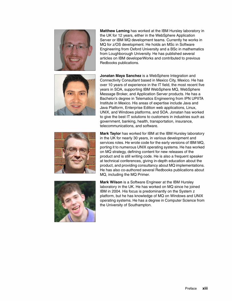
Matthew Leming has worked at the IBM Hursley laboratory in the UK for 12 years, either in the WebSphere Application Server or IBM MQ development teams. Currently he works in MQ for z/OS development. He holds an MSc in Software Engineering from Oxford University and a BSc in mathematics from Loughborough University. He has published several articles on IBM developerWorks and contributed to previous Redbooks publications.
Jonatan Maya Sanchez is a WebSphere Integration and Connectivity Consultant based in Mexico City, Mexico. He has over 10 years of experience in the IT field, the most recent five years in SOA, supporting IBM WebSphere MQ, WebSphere Message Broker, and Application Server products. He has a Bachelor’s degree in Telematics Engineering from IPN UPIITA Institute in Mexico. His areas of expertise include Java and Java Platform, Enterprise Edition web applications, Linux, UNIX, and Windows platforms, and SOA. Jonatan has worked to give the best IT solutions to customers in industries such as government, banking, health, transportation, insurance, telecommunications, and software.
Mark Taylor has worked for IBM at the IBM Hursley laboratory in the UK for nearly 30 years, in various development and services roles. He wrote code for the early versions of IBM MQ, porting it to numerous UNIX operating systems. He has worked on MQ strategy, defining content for new releases of the product and is still writing code. He is also a frequent speaker at technical conferences, giving in-depth education about the product, and providing consultancy about MQ implementations. He has also co-authored several Redbooks publications about MQ, including the MQ Primer.
Mark Wilson is a Software Engineer at the IBM Hursley laboratory in the UK. He has worked on MQ since he joined IBM in 2004. His focus is predominantly on the System z platform, but he has knowledge of MQ on Windows and UNIX operating systems. He has a degree in Computer Science from the University of Southampton.
Preface xiii

Thanks to the following people for their contributions to this project:
Tamikia Barrow, Paul Alexander Frank, Shawn Tooley, Debbie Willmschen International Technical Support Organization, Raleigh Center
Morag Hughson, Colin Paice, Maya Raja, Andrew Akehurst-Ryan, Tony Sharkey, Pete Siddall, Gwydion Tudur, David WareIBM MQ Development, Performance, ArchitectureIBM Hursley
T. Rob Wyatt, ConsultantIoPT Consulting
Rich Conway, Robert Haimowitz IBM Development Support Team, IBM Poughkeepsie
Now you can become a published author, too!
Here’s an opportunity to spotlight your skills, grow your career, and become a published author—all at the same time! Join an ITSO residency project and help write a book in your area of expertise, while honing your experience using leading-edge technologies. Your efforts will help to increase product acceptance and customer satisfaction, as you expand your network of technical contacts and relationships. Residencies run from two to six weeks in length, and you can participate either in person or as a remote resident working from your home base.
Find out more about the residency program, browse the residency index, and apply online at:
ibm.com/redbooks/residencies.html
Comments welcome
Your comments are important to us!
We want our books to be as helpful as possible. Send us your comments about this book or other IBM Redbooks publications in one of the following ways:
� Use the online Contact us review Redbooks form found at:
ibm.com/redbooks
� Send your comments in an email to:
� Mail your comments to:
IBM Corporation, International Technical Support OrganizationDept. HYTD Mail Station P0992455 South RoadPoughkeepsie, NY 12601-5400
xiv IBM MQ V8 Features and Enhancements

Stay connected to IBM Redbooks
� Find us on Facebook:
http://www.facebook.com/IBMRedbooks
� Follow us on Twitter:
https://twitter.com/IBMRedbooks
� Look for us on LinkedIn:
http://www.linkedin.com/groups?home=&gid=2130806
� Explore new Redbooks publications, residencies, and workshops with the IBM Redbooks weekly newsletter:
https://www.redbooks.ibm.com/Redbooks.nsf/subscribe?OpenForm
� Stay current on recent Redbooks publications with RSS Feeds:
http://www.redbooks.ibm.com/rss.html
Preface xv

xvi IBM MQ V8 Features and Enhancements

Part 1 Introducing IBM MQ V8 and new features
In this part, we describe features of IBM MQ V8 that are available on both Distributed and z/OS platforms.
This part consists of the following chapters:
� Chapter 1, “Introduction” on page 3
� Chapter 2, “Topic host routed publish/subscribe” on page 15
� Chapter 3, “User authentication” on page 33
� Chapter 4, “TLS/SSL Digital Certificate Management” on page 47
Part 1
© Copyright IBM Corp. 2014. All rights reserved. 1

2 IBM MQ V8 Features and Enhancements

Chapter 1. Introduction
This chapter briefly introduces IBM MQ and gives an overview of functions that are new or enhanced in MQ V8.
This chapter contains the following topics:
� 1.1, “What is IBM MQ” on page 4� 1.2, “What is new in IBM MQ V8” on page 6� 1.3, “Supported environments” on page 13
1
© Copyright IBM Corp. 2014. All rights reserved. 3

1.1 What is IBM MQ
Business environments are constantly changing. Applications that were written 20 years ago need to exchange data with applications written last week. Examples of this changing environment can be one company that is merging with another, a new partner to communicate with, an application that is used internally within a company is now exposed to customers, or different departments within a company need to share programs.
The growth of Internet banking requires services, such as managing payments or querying account information, to be made available through a range of channels. The core data can be held in a database on a mainframe, but a user of a browser requires a front-end web application server to interact with that database. As new delivery channels are created, such as a smartphone application, easy ways for that new mechanism to interact are needed. The smartphone application must communicate with the same applications and database without changing the database.
The evolutionary speed of IT systems makes essential the ability to integrate across many environments with multiple applications reliably and quickly.
Messaging is an effective way to connect these systems. It hides many of the details of communication from the application developer and gives a simple interface. Simplifying allows the developer to concentrate on the business problem instead of worrying about matters such as recovery, reliability, and operating system differences.
Another feature of messaging solutions is the decoupling of one application from another. Many mechanisms for communicating between applications require that both are available at the same time. Messaging uses an asynchronous model, meaning that an application that is generating messages does not have to run at the same time as an application consuming those messages. Reducing the requirements for simultaneous availability reduces complexity and can improve overall availability. Messages can be sent to specific applications or distributed to many separate applications at the same time.
MQ also is in the business of connecting systems and applications, regardless of platform or environment. It is essential to be able to communicate between a GUI desktop application that is running on Windows and an IBM CICS transaction that is running on IBM z/OS. That value of universality is core to the product, and has not changed in the time it has been available. What has changed is the range of environments in which MQ can or must operate.
Newer platforms, environments, requirements for qualities of service, and newer messaging patterns exist. Security is more important as systems are made accessible to more users across an enterprise and beyond it. Performance and scalability requirements continue to increase. Regulators and auditors impose more controls on what can or must be done. Systems, which need access to enterprise data, became both more powerful (faster, more
IBM MQ name change: IBM MQ is the market-leading messaging integration middleware product. Introduced in 1993 under the IBM MQSeries® name, it focused on providing an available, reliable, scalable, secure, and high-performance transport mechanism. The product name was changed to IBM WebSphere MQ, and now with Version 8, it is now named IBM MQ.
Although the official product name is now changed, this change was made too late in the development cycle for any changes to be made to the code or names of documents. So, for now, the WebSphere MQ phrase continues to appear in those places.
4 IBM MQ V8 Features and Enhancements
CPUs, and so on) and much less powerful (sensors, tablets, and mobile phones). Therefore, MQ evolves.
There are now more ways for applications to reach an MQ queue manager and get access to any existing applications that were already MQ enabled. New applications can be written that use alternative interfaces and still maximize the reliability and performance of MQ. Those new applications do not need a complete replacement of existing infrastructure. The applications work with what you already have and know how to manage.
At the same time as adding new interfaces, protocols, and environments, much MQ workload continues to be executed in mainframe-based data centers. Efficient use of, and integration with, the capabilities of the z hardware and operating systems is critical. As this book shows, MQ V8 for z/OS significantly improves the performance, capacity, and availability that can be achieved when it is running in a sysplex.
Whether the official name is MQSeries or WebSphere MQ or MQ, the fundamental value of the product has remained unchanged. Its role is to enable connection and communication between disparate applications running on a wide range of platforms by providing a reliable, secure, high-performance backbone with a simple programming model.
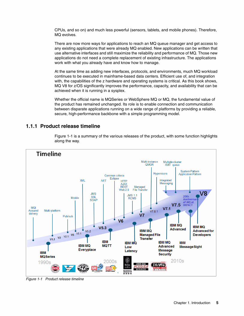
1.1.1 Product release timeline
Figure 1-1 is a summary of the various releases of the product, with some function highlights along the way.
Figure 1-1 Product release timeline
Chapter 1. Introduction 5

Version 7.1 was a major release in 2011 and delivered enhancements across all the main platforms including z/OS. Version 7.5 followed soon after for a subset of the distributed platforms. V7.5 was primarily an exercise in repackaging separate products and features into a single offering but it did include a few technical enhancements that were not made available on the platforms that remained at V7.1. Therefore, part of the V8 release was to bring all the operating systems (platforms) to a similar level of function.
1.2 What is new in IBM MQ V8
IBM MQ V8 was made available in June 2014. It contains enhancements in a range of areas including security, availability, performance, capacity, and standards support. Many of these features are available for all of the V8 platforms; some are aimed at using z/OS and the System z hardware capabilities. This section is a brief description of the entire product release; later chapters have more detail about many of the functions. Not all features listed here are covered in detail in this book.
Many features of this release were customer-driven requests for enhancements (RFEs). The “Delivered RFEs in MQ V8” blog post describes RFEs and how to submit them to be included in future versions of IBM MQ:
https://www.ibm.com/developerworks/community/blogs/messaging/entry/delivered_rfes_in_mq_v8?lang=en
As mentioned, although the official product name is now changed, this change was made too late in the development cycle for any changes to be made to the code or names of documents. So, for now, the WebSphere MQ phrase continues to appear in those places.
1.2.1 Security
IBM MQ V8 includes many security features, which are described here.
User authenticationSince V6, applications are able to specify a user ID and password when connecting to a queue manager. However, that information was mostly ignored by the queue manager, with the actual validation of the password being delegated to user-supplied exits.
With IB MQ V8, authentication is now possible in the queue manager. On all platforms, a password can be verified against the local operating system; on distributed platforms, an additional option checks passwords directly against an LDAP repository.
The application might be locally connecting, or be a client connecting remotely. Configuration options tell the queue manager whether passwords are required. For client programs that cannot be easily updated to include password information, a channel exit is provided that can insert user IDs and passwords during the connection process.
When passwords need to flow across the network, they are protected from casual network sniffing, even if Transport Layer Security with Secure Sockets Layer (TLS/SSL) is not used when connecting V8 clients to V8 queue managers. This is described in 3.10, “Password protection on the network” on page 43.
Several product-provided programs, including runmqsc, are updated to allow user ID and password information to be provided as command parameters.
6 IBM MQ V8 Features and Enhancements

Authorization on UNIX and Linux systemsThe IBM MQ authorization design on UNIX systems has traditionally been based only on groups. Updates to a user’s authority have always affected that user’s primary group. This was known to cause confusion (“why does user Y now have access to a queue when I granted it only to user X?”) and sometimes inadvertently giving more rights to people than intended.
V8 gives an option for the UNIX model to match the Windows model, where setting permissions for a user does really mean setting permissions for that user and no other user.
Channel authentication (CHLAUTH) rulesA major feature of V7.1 was the introduction of authentication rules for channels. These gave options to block connections or select the identity to be used for the connection based on information such as IP addresses or the inbound identity.
After V7.1 was released, requests soon arrived for an enhancement to permit the use of host names and not only IP addresses in these rules. IBM MQ V8 extends the rules to allow these names. It also extends the mapping rules to coexist with user authentication processing, giving further flexibility in selecting which identity will be used for authorization checks.
A further enhancement in CHLAUTH processing is the addition of the SSLCERTI attribute, processed when checking whether a certificate matches one of the SSLPEERMAP rules. Along with the SSLPEER attribute, it verifies that the subject’s distinguished name (DN) matches, and also that the DN belongs to the issuer of the certificate.
Certificate handling for TLS/SSL secure channelsIBM MQ refers to certificates in its keystores by a label. This label is a short reference to allow the system to pick the correct certificate from a keystore. Before V8, the label for certificates was required to follow a strict naming convention (for example, ibmwebspheremq<qmgrname>). V8 allows configuration of the label to use for each client, each queue manager, and each queue sharing group instead of requiring a specific format for the label.
A further enhancement gives the option of channel-specific labels. This is intended for scenarios where some channels might want to connect to a partner that uses a different certificate issuing authority; a single queue manager can now use multiple certificates for the different paths into it. This function requires both ends of a channel to be at V8 and it is not currently available for all types of clients.
1.2.2 Performance and scalability
On both the Distributed and z/OS products, improvements to performance have occurred in queue manager. As always, performance reports are created for many of the platforms and are available at this address:
http://www.ibm.com/support/docview.wss?rs=171&uid=swg27007150
In general, no changes are needed to applications or configurations to benefit from these performance boosts. However, one particular aspect is the use of SHARECNV on SVRCONN channels. On distributed platforms, much optimization of SHARECNV(1) channels exists and this is now the preferred setting even though it is not the default value.
The chart at Figure 1-2 on page 8 is one example of how performance improved from V7.5 to V8. The top (red) line shows the V8 code reaching about 8000 transactions in a second; the lower (green) line shows the V7.5 reaching only about 6000 transactions per second.
Chapter 1. Introduction 7

Figure 1-2 Comparing V7.5 persistent message rates with a beta V8 release
Topic host routed publish/subscribeAn option for publish/subscribe network topologies was added. Topics in a publish/subscribe cluster can now be defined as hosted by a subset of the queue managers in the cluster. The goal of this option is to significantly reduce the communications (both number of channels and number of messages) that take place between members of the cluster, and therefore having larger clusters is now possible.
An example of where this becomes useful is in a typical branch/hub topology where each branch needs to communicate with systems in the center, but do not need to communicate with each other. Before V8, all of these systems needed direct channels running, and all subscription and topic information was passed between all of the queue managers even if publications never needed to flow between some of these systems. With V8, each branch communicates with the queue managers in the hub, but not directly with other branches.
This feature is described in Chapter 2, “Topic host routed publish/subscribe” on page 15.
There have been other internal changes to the publish/subscribe implementation to make it more efficient, for example to handle large numbers of topics.
1.2.3 System z exploitation
In addition to features that are common to all the MQ platforms, this release continues a theme of taking advantage of new IBM System z and z/OS hardware and software features.
The 64-bit buffer poolsIBM MQ for z/OS stores messages for private queues in memory (buffer pools), writing only the message data to disk (page sets) when required to keep memory available for new messages. With MQ V8, these buffer pools can be defined to be located in 64-bit storage,
8 IBM MQ V8 Features and Enhancements

giving a potentially huge amount of space for message data. When buffer pools were constrained to a 31-bit address space, and after accounting for the queue manager’s other storage needs and system requirements, a maximum of approximately 1 GB was available for messages. A 64-bit buffer pool implementation theoretically extends the space for messages to about 16 EB, although trying to use all of that is not recommended.
A further enhancement to the buffer pool design allows an administrator to define that the buffer pool is in page fixed memory (that is, it will not be paged out). If the system has sufficient real memory available to it, this can be an extra performance boost.
For certain types of workload, performance and capacity are improved, reducing the number of I/O requests.
In addition to changing the size of buffer pools, the number that can be defined is increased to 100, which is the same as the number of page sets. With this change, seeing the relationship between page sets and buffer pools is easier and therefore simplifies managing the tuning that can be done to further improve performance.
More details about this feature are in Chapter 5, “Buffer pool enhancements” on page 73.
Extended log RBAThe log RBA (relative byte address) is a number that starts at zero when a queue manager is created and then increases as log records (for example, for persistent messages) are written. If that number reaches its maximum value, then the queue manager has to stop and various reset activities have to take place to bring it back to zero and start counting again.
This number has always been 6 bytes wide, which was thought sufficient 20 years ago when MQ was created, but improvements in hardware and software mean that busy queue managers might now wrap the counter every 12 - 18 months. As the reset process requires the queue manager to be stopped, this is clearly not something that is desirable for highly available systems.
MQ V8 extends the log RBA from 6 bytes to 8 bytes, making it far less likely to reach the maximum. At current performance levels, calculations suggest it will not wrap for thousands of years. Although systems will of course improve, there is plenty of room before the size must be further increased.
Migrating a queue manager to use the new format RBA and further discussion of the feature are in Chapter 6, “Extending the log RBA and conversion” on page 85.
System Management Facilities (SMF) reportsIn this release, reporting of activity through SMF is enhanced to include data on channels and the channel initiator. This gives much better visibility of the behavior of a queue manager and its interactions with other systems.
A correlator field in the SMF records was added to help more easily relate information that is generated by CICS about its transactions to the corresponding operations performed in MQ by those transactions.
More information about SMF enhancements is in Chapter 7, “SMF changes: Channel initiator statistics and channel accounting” on page 105.
Chapter 1. Introduction 9

Hardware feature supportCompression of data being sent across a channel was a new feature of MQ V6. With V8, this activity can be offloaded to the zEDC compression accelerator, reducing CPU costs and improving performance.
A new capability of the zEC12 and zBC12 servers is Flash Express to extend the storage available for coupling facility structures. Supporting this feature in IBM MQ is a way of providing cost-effective capacity for shared queues that might otherwise overflow when there is an unexpected glut of messages.
Read more about these features in Chapter 8, “Using new System z features” on page 125.
LP64 applicationsC applications that the batch and RRS adapters are now supported with 64-bit interfaces to the Message Queue Interface (MQI).
Client Attach Facility (CAF)Licensing terms have changed to remove any charge for connecting clients to z/OS. With V8, the Client Attach Facility (CAF) feature does not even exist. However, just because it is now “no charge” to connect clients to a z/OS queue manager, the activity invoked by client applications will still cost CPU cycles on the queue manager and so architectures that intend to use MQ clients must still consider these runtime costs.
Because the ability to connect clients is now available by default, consider using CHLAUTH rules to block connections if you previously did not use the CAF.
1.2.4 Cross-product consistency
One of the features added to MQ V7.5 was an extension for clustering, to permit the use of multiple transmission queues. This is now available in all the V8 platforms, including IBM System z and IBM System i® which did not have a V7.5 release.
Similarly, the Advanced Message Security (AMS) and Managed File Transfer (MFT) features are more closely integrated in this release. For the IBM i platform, this is the first time that AMS has been available; on z/OS, the implementation is simplified.
Because AMS, MFT, and the multiple cluster transmission queue features are extensively described in previous books, they are not covered further here. With the integration, the AMS and MFT features look more natural to the platform, but no significant new function is provided. On z/OS, AMS and MFT are still separately priced and licensed, but the technical foundation is improved.
1.2.5 Usability
This release contains several features to help you more easily use IBM MQ.
Administration with runmqsc programA common requirement has been to permit users of MQ to at least look at the resources they are using, for example to see queue depths. This is especially useful for application developers who want to test their code without having full MQ admin rights.
Rather than require the use of a program such as the MQ Explorer, the runmqsc program is now installed to be runnable by any user instead of being restricted to only the default MQ
10 IBM MQ V8 Features and Enhancements

administrator groups. The operations executed by runmqsc are of course still checked for authorizations, so not everyone can define or delete queues, but this removes the need to do something like invoke the runmqsc program in a sudo command wrapper.
This runmqsc command is enhanced in other ways. It now accepts a user ID and password to support real authentication of the person attempting to administer MQ.
It also can work in ways that were accessible through the MO72 SupportPac but were not part of the real MQ product:
� It can run as a client, connecting directly to remote queue managers instead of requiring a local queue manager.
� It can run completely disconnected from any queue manager, with sufficient function to create and edit the MQ Client Channel Definition Table (CCDT). That makes it much simpler for users to generate their own individual CCDT without requiring MQ system administrators to create and distribute these files.
Looking at publish/subscribe statusInformation about publish/subscribe status is now available at an aggregated level for the whole queue manager. Instead of having to issue queries to find all of the in-use topics and count the number of subscriptions associated with each of those topics, a single command shows the totals directly. An unexpected spike in these numbers might, for example, be a quick indication of a rogue application. Example 1-1 shows a runmqsc session to query the publish/subscribe summary status.
Example 1-1 Publish/subscribe summary status
DISPLAY PUBSUB ALL 1 : DISPLAY PUBSUB ALLAMQ8723: Display pub/sub status details. QMNAME(QM1) TYPE(LOCAL) STATUS(ACTIVE) SUBCOUNT(241) TPCOUNT(105)
Message suppression on z/OSThe z/OS queue manager generates messages for the console to show some system information. However, some administrators consider several of these messages to be unimportant and unnecessary. The administrators prefer to not see these messages in the logs. Most common are messages that are related to channel start and stop activity.
Messages can be inhibited from appearing in the console by a write to operator (WTO) exit, but that still incurs the cost of generating the message in the first place.
A service parameter in previous releases allowed suppression of some of these messages. V8 formalizes and extends this option with a EXCLMSG zParm value. A list of message numbers is provided, and the queue manager no longer generates these messages. To help with distinguishing client channel activity from other channels, message numbers X511 and X512 are introduced for SVRCONN channels, which can be suppressed independently.
Copying messagesA dmpmqmsg command is introduced in V8. This gives options to copy messages to or from a file for editing, saving, replaying, and so on. If it seems familiar, that is because it is essentially a renamed version of the qload utility (SupportPac MO03). Few changes were made to it beyond the new name.
Chapter 1. Introduction 11

1.2.6 Platforms: 64-bit and 32-bit
This release moves the implementation of IBM MQ on Windows to be a true 64-bit product. This matches the UNIX products, which have been 64-bit for several releases, and will increase the capacity, such as the number of messages that can be held on queues. Applications do not need to be modified because both 32-bit and 64-bit application libraries are still provided; however, some exits might need to be recompiled to be executable in a 64-bit environment.
The default installation directory is now c:\program files\ibm\websphere mq, even on 64-bit versions of Windows (previously it was c:\program files (x86)\ibm\websphere mq). The default data directory moved to c:\programdata\ibm\mq (the inconsistency in the use of spaces in these paths is from Windows; it is not an MQ choice). Although the queue manager code is now 64-bit, the V8 installation can successfully coexist with earlier installations of MQ that are 32-bit.
There is still a 32-bit installation package for the MQ client on Windows.
1.2.7 Standards and APIs
For Java programmers, this release supports the most recent Java Message Service (JMS) standard. For Windows programmers who use the .Net framework, this release enhances the .Net and WCF interfaces to IBM MQ.
JMS 2.0During 2013, a long-awaited update to the JMS specification was finally ratified. JMS 2.0 tidies up some issues that were found in the previous JMS 1.1 standard. It uses new features of the Java language such as the java.lang.AutoCloseable interface that were introduced in Java 7, and brings in several other new features.
Perhaps the most interesting capability in JMS 2.0 is the Delivery Delay option. This allows an application to put or publish a message, asserting that the message is not to be available for consuming applications until some future time. It is like the opposite of the Expiry option, where messages are automatically made unavailable after a period of time.
In MQ, this is implemented by the message being (transparently) put first to an intermediate staging queue (SYSTEM.DDELAY.LOCAL.QUEUE). A scanning task inside the queue manager then moves the messages to the real destination when the specified delay has been reached. This function is available only for applications that use the JMS API and has not been exposed to other interfaces, such as the MQI.
JMS 2.0 can be used by stand-alone applications directly. A Resource Adapter is also provided for applications running inside application servers that support the Java Platform, Enterprise Edition 7 standard.
More information about JMS 2.0 is at the following web page:
https://java.net/projects/jms-spec/pages/JMS20FinalRelease
.Net and WCFClient applications that use .Net classes for MQ are now able to use TLS/SSL communications to the queue manager without requiring use of the MQ C client libraries and its embedded security code. This means that secure .Net applications can be fully managed within the .Net framework. Because this is using the Microsoft SSLStream classes, it integrates with the Windows native certificate stores instead of the MQ kdb keystores.
12 IBM MQ V8 Features and Enhancements

An alternative API for Windows applications is called WCF (Windows Communication Framework). This is a transport-independent API with no direct knowledge in the program of which protocol underlies communication to other programs. Configuration of the application uses a URI such as wmq://host.example.com/msg/queue/QUEUE1 to identity endpoints. The first implementation of the MQ WCF interface assumed messages were always sent with SOAP headers. With V8, the interface is extended to more easily send messages to applications that are not expecting to process SOAP or MQRFH2 headers.
1.3 Supported environments
MQ V8 is available for a range of operating systems and hardware platforms. For more information about supported environments see the following web page:
http://www.ibm.com/support/docview.wss?uid=swg27041395
Chapter 1. Introduction 13

14 IBM MQ V8 Features and Enhancements

Chapter 2. Topic host routed publish/subscribe
Before IBM MQ V8, you could implement a distributed publish/subscribe in one of two ways:
� By creating a topic hierarchy� By implementing publish/subscribe in a queue manager cluster
MQ V8 now offers two ways of setting up clustered publish/subscribe. In contrast to the established method, now known as direct routing, you can implement topic host routing that uses a “hub” model for message distribution.
This chapter investigates topic host routing scenarios and adaptability to different situations, and provides an introduction to experiments you can do with MQ publish/subscribe. It also demonstrates several new commands and MQ Explorer facilities to help you more easily monitor the activity of publish/subscribe clusters.
All forms of publish/subscribe are available on all MQ platforms. Distributed publish/subscribe refers to the situation where publishers and subscribers are located on different queue managers (which can themselves be located on the same or different physical systems running various operating systems).
This chapter contains the following topics:
� 2.1, “Introduction” on page 16� 2.2, “Distributed publish/subscribe topologies” on page 19� 2.3, “Comparison of topologies” on page 27� 2.4, “Performance tips” on page 29� 2.4, “Performance tips” on page 29� 2.5, “Problem determination” on page 30
2
© Copyright IBM Corp. 2014. All rights reserved. 15

2.1 Introduction
Before MQ V8, you implemented distributed publish/subscribe in either of two ways:
� You could create a queue manager hierarchy by manually establishing relationships between parent and child queue managers.
� You could create a cluster of queue managers in such a way that a message published on one queue manager was distributed to all the others in the cluster that had subscribers waiting for that publication. You achieved this by defining an administrative topic object on any queue manager in the cluster so that all the queue managers become aware of all the publish/subscribe knowledge in the cluster.
Before MQ V8, this second way of setting up publish/subscribe in clusters meant that publications went straight from the publisher to every subscriber. It was quick and easy in that the communication is always direct.
However, it also meant that, in general, every queue manager in the cluster had to be aware of what was going on and where all the subscribers were, which was wasteful, and caused problems if you tried to scale the cluster to include many queue managers.
Therefore, a new mode of working exists in V8 clusters. The established way of configuring publish/subscribe is known as direct routing, to distinguish it from the new topic host routing.
If you use topic host routing, a publication is not sent directly to the subscriber, but goes through an intermediate “hub” queue manager (the topic host) that gets messages from the publisher and forwards them to the queue managers of any subscribers that want them. In this mode, only the topic host must be aware of other queue managers that have subscribers associated with them, which makes this configuration much more scalable.
16 IBM MQ V8 Features and Enhancements

2.1.1 The example case
The simple topic tree, shown in Figure 2-1, is used throughout this chapter to demonstrate publish/subscribe messaging concepts, tools, and techniques. It represents the partial implementation of the output of a news agency.
Figure 2-1 Sample topic tree showing the topic strings associated with several nodes in the tree
Consider a news provider with an online application that has news feeds in different sections. There might be information about the weather (Will it be good for a walk and do I need to take a sun hat or a rain hat?). There might be an opinion about the last debate between all the candidates for the next election of the mayor of the city.
The provider also wants to cater to the tennis fans who want to know the current status of matches that are being played, and who want news of scores in real time (short-lived information that is transient and has little or no value to them after the moment passes). They might also want more “static” information such as player biographies and other articles.
Another group of people, on the other hand, might not be interested in tennis at all, and want information about another sport such as football, and so information about football needs to be kept separate from information about tennis.
The news provider wants all the information to be available in such a way so that the various consumers can select, through web pages, what information they want, and then as that relevant information becomes available, it can then be sent to each consumer.
/News/Sports/Tennis
/News/Sports
/News/Sports/Tennis/Wimbledon
/News/Politics
/News/Sports/Football
Topic string
Topic node
Australia US
France Wimbledon
Tennis
PoliticsWeatherSports
Football
root
News
Chapter 2. Topic host routed publish/subscribe 17

2.1.2 Terminology
For a general overview, see the “Publish/subscribe components” topic in the MQ V8 Product overview section:
http://www.ibm.com/support/knowledgecenter/SSFKSJ_8.0.0/com.ibm.mq.pro.doc/q004890_.htm
The following list defines several terms that are used in this chapter. A more complete discussion is in IBM Knowledge Center at the addresses listed in the definitions.
� Topic string: A string of characters that describes the subject of the information that is requested by a subscriber. Topic strings use the forward slash (/) character as a separator, to represent levels in the topic tree. Subscriptions (but not publications) can use wildcard characters to represent lower levels in the topic tree.
– http://www.ibm.com/support/knowledgecenter/SSFKSJ_8.0.0/com.ibm.mq.pro.doc/q005000_.htm
– http://www.ibm.com/support/knowledgecenter/SSFKSJ_8.0.0/com.ibm.mq.ref.dev.doc/q100210_.htm
� Topic tree: A structure that is constructed by combining all the available topic strings. The topic strings are split at the forward slash (/) separator into strings that represent nodes in the tree.
http://www.ibm.com/support/knowledgecenter/SSFKSJ_8.0.0/com.ibm.mq.pro.doc/q005050_.htm
� Topic object: An MQ object that specifies a topic string, which associates it with a particular node in the topic tree, that has attributes that define the behavior of that node (and often, all the nodes below it in the tree).
http://www.ibm.com/support/knowledgecenter/SSFKSJ_8.0.0/com.ibm.mq.pro.doc/q003320_.htm
� Subscribers and subscriptions: A subscriber is an application, related to a subscription, that consumes messages that are produced by publishers about a specific topic. A subscription is an object attached to a queue manager that contains a topic string, which defines what subjects the subscriber is interested in, and details about where messages are to be delivered. They can be created manually by using an MQSC command or by an application.
http://www.ibm.com/support/knowledgecenter/SSFKSJ_8.0.0/com.ibm.mq.pro.doc/q004950_.htm
� Publishers and publications: An application that produces MQ messages (known as publications) that are related to a stated topic, and makes them available to a queue manager. A publisher can produce messages about any topic.
http://www.ibm.com/support/knowledgecenter/SSFKSJ_8.0.0/com.ibm.mq.pro.doc/q004920_.htm
� Subscription durability: The configuration determines what happens to a subscription when the subscriber disconnects from a queue manager. If the subscription is durable, it keeps receiving publications even if the subscriber is not connected. A nondurable subscription is maintained only while the subscriber remains connected to the queue manager.
http://www.ibm.com/support/knowledgecenter/SSFKSJ_8.0.0/com.ibm.mq.pro.doc/q004970_.htm
� Proxy subscription: A subscription created by a queue manager and sent to other queue managers (subscription propagation) so that publications can be sent to all queue managers that have subscribers requesting publications on the subscription’s topic. Duplicate subscriptions are aggregated. You can restrict the propagation of proxy subscriptions at the cost of publications being sent to all queue managers.
http://www.ibm.com/support/knowledgecenter/SSFKSJ_8.0.0/com.ibm.mq.pro.doc/q005140_.htm
18 IBM MQ V8 Features and Enhancements

2.2 Distributed publish/subscribe topologies
In a distributed topology, multiple queue managers can be connected; mechanisms are provided that enable publications to be propagated to subscriptions at different locations, even if they are defined remotely. Thus subscribers to a topic-connected queue manager can receive messages that have been published at another queue manager. In this way, the subscriber is decoupled from the publisher and the constraint of needing to use the same queue manager for both is removed.
Within a distributed configuration, you can create different “topologies” of queue managers. An important aspect to consider, at the design stage, is what the appropriate topology of a publish/subscribe network is, especially when you anticipate a large number of potential destinations. You can decrease the complexity of a publish/subscribe network by making the correct choices at the design stage.
Figure 2-2 shows a hierarchy topology. The squares are queue managers, the circle surrounds a cluster, the thin connecting lines represent queue managers connections made by hierarchy relationships, and the arrows show publication routes.
Figure 2-2 Hierarchy topology
You can either connect queue managers manually in a publish/subscribe parent and child hierarchy, or you can create a publish/subscribe clustered topic. In MQ V8, you can also choose whether to use a direct routed publish/subscribe cluster or a topic host publish/subscribe cluster. You can also combine both clusters and hierarchies in the same topology.
Figure 2-3 on page 20 shows a direct routed topology. The squares are queue managers, the circle surrounds a cluster, the thin connecting lines represent direct queue managers connections made by clustered topic definition, and the arrows show publication routes.
Figure 2-4 on page 20 shows a topic host routed topology. The squares are queue managers, the circle surrounds a cluster, the thin connecting lines represent queue managers connections to the topic host made by clustered topic definition, and the arrows show publication routes
Publisher
Subscriber
Subscriber
Chapter 2. Topic host routed publish/subscribe 19

Figure 2-3 Direct routed topology
Figure 2-4 Topic host routed topology
The advantages and disadvantages of the topologies are described in 2.3, “Comparison of topologies” on page 27.
DIRECT
Publisher
Subscriber
TOPIC HOST
Publisher
Subscriber
20 IBM MQ V8 Features and Enhancements

2.2.1 Proxy subscriptions
When a distributed publish/subscribe network architecture is implemented, publications typically occur at one network location and the subscriptions at another. Whether your distributed publish/subscribe network is a hierarchy or a cluster of queue managers, MQ uses proxy subscription objects to allow this to occur. Proxy subscriptions are created by a queue manager for each unique topic string subscribed to on that queue manager, and the proxy subscriptions are propagated to all other queue managers so that publications can be directed to the appropriate recipients.
The way that a proxy subscription is created depends on the value of the PROXYSUB attribute of the topic object definition. This attribute controls when proxy subscriptions are created. By default, it has the value FIRSTUSE and thus proxy subscriptions are generated automatically in the queue manager only when a user subscription is created for a topic. Alternatively when the attribute has the value FORCE, proxy subscriptions are created even when no local user subscriptions exist.
Subscription propagationProxy subscriptions are created automatically and the IBM MQ publish/subscribe engine provides this mechanism that does these tasks:
� Eliminates duplicated messages at the subscriber location.
� Handles subsequent subscriptions conveniently for resource administration.
� Ensures that the minimum required amount of copies of a message forwarded from the publisher to the subscriber were sent.
� Filters out discrepancies to reduce overhead.
IBM MQ V8 has made significant improvements in the way that it handles topic strings and topic nodes to reduce the consumption of resources. Nodes are validated periodically to determine if they are still being used, and unused topics are erased. This can best be used with a design that incorporates the best combination of properties from the administrative topic object, such as subscription scope (SUBSCOPE), publication scope (PUBSCOPE), wildcard (WILDCARD), publish (PUB), subscribe (SUB), and cluster route (CLROUTE) by their given values, thereby building an efficient configuration.
When a queue manager cluster or a hierarchy is declared, the subscription to a topic string is resolved by the publish/subscribe engine through established channels and ports between queue managers in the network. The paths that a published message follows at the moment that it will be delivered from the publisher to the subscriber locations behaves in the way defined by the parent-child relationships or by the cluster routing parameter.
Proxy subscriptions are not unique to clusters. If you have a queue manager hierarchy, proxy subscriptions are propagated to both the parent queue manager and child queue managers.
Note: When you configure an MQ V8 topic object with the PROXYSUB parameter set to FORCE, the last level of the topic string will be a wildcard with the number sign (#) character. No more individual proxy subscriptions are generated for a topic string with topic nodes below the last level of the topic tree. The subscribers at that topic string will share the wildcarded subscription.
Chapter 2. Topic host routed publish/subscribe 21

2.2.2 Hierarchies
Connections in a hierarchy are achieved by defining the parent queue manager of each queue manager in the hierarchy (except the root queue manager) by using the following MQSC command:
ALTER QMGR PARENT (parent_queue_manager_name)
All queue managers in a hierarchy must have unique names.
When defining child/parent relationships between queue managers, propagation of publications between queue managers in the hierarchy occur based on the PUBSCOPE and SUBSCOPE topic properties.
Publications received on any queue manager are then routed through the hierarchy to each queue manager that hosts a matching subscription.
If the queue managers are also in a cluster, an important consideration is to not use the cluster name setting of a topic to add the topics into the cluster. If you use the cluster name, the topology becomes a publish/subscribe cluster and does not honor the child/parent hierarchy relationships that are defined.
To see the status of these relationships, use the following MQSC command at each location:
DISPLAY PUBSUB ALL
Review the value of the TYPE parameter and the STATUS parameter, which show you whether the queue managers are properly connected and aware of each other.
Check both queue manager error logs for possible errors.
For more information about defining hierarchies, see the “Routing in publish/subscribe hierarchies” topic in the IBM WebSphere MQ V8 Planning section of IBM Knowledge Center:
http://www.ibm.com/support/knowledgecenter/SSFKSJ_8.0.0/com.ibm.mq.pla.doc/q005131_.htm
2.2.3 Clusters
An important concept within MQ is that of clustered queue managers. Publish/subscribe capabilities within clusters have been enhanced and made more flexible in MQ V8.
With only one attribute in the topic definition, the topic tree is built in the local queue manager and that definition is published across the cluster channels to all members of the cluster. These queue managers are asynchronously made aware of publish/subscribe activities, which, although physically separated, are logically coordinated.
This distributed publish/subscribe behavior can coexist with any publish/subscribe activity on a local queue manager.
For direct routing in a cluster, the proxy subscriptions are propagated to all cluster members, whereas for topic host routed configurations, proxy subscriptions are propagated only to the cluster members that have declared the relevant administrative topic object, which means to the topic hosts (see the next section, 2.2.4, “Direct routed clustered topics” on page 23).
Note: In MQ V8 the PUB attribute behavior for the topic has changed. If at least one topic definition in the cluster has the value PUB(ENABLED), publications are accepted. For local definitions, this value precedes all clustered ones regardless of their values.
22 IBM MQ V8 Features and Enhancements

2.2.4 Direct routed clustered topics
As its name suggests, a direct routed cluster topology means that publication messages are sent directly from a publishing queue manager to the subscribing queue managers.
After you create a topic object, you can use MQ V8 commands that offer improved visibility of values associated with the topic. See Example 2-1. Most important, check the value of CLSTATE because this value is related to the state of the clustered topic in that queue manager.
If this cluster state value is a status other than ACTIVE, a problem exists and you should investigate. If you find an incorrect topic definition, remove it from the cluster and define it correctly.
Example 2-1 Output from display topic attributes of cluster type topics command
DISPLAY TCLUSTER(*) TOPICSTR CLUSQMGR CLROUTE CLSTATEAMQ8633: Display topic details. TOPIC(TENNIS.TOPIC) TYPE(CLUSTER) TOPICSTR(/News/Sports/Tennis) CLUSQMGR(PS02) CLROUTE(DIRECT) CLSTATE(ACTIVE)
The DISPLAY TCLUSTER command produces the same output as the full DISPLAY TOPIC TYPE(CLUSTER) command, but does not need to include the TYPE parameter, and therefore is used in the examples throughout this chapter. See the description of these commands in the IBM Knowledge Center:
http://www.ibm.com/support/knowledgecenter/SSFKSJ_8.0.0/com.ibm.mq.ref.adm.doc/q086380_.htm
Direct routing is the simplest way to enable a publish/subscribe network. In this configuration, all queue managers in the cluster become aware of all other queue managers in the cluster and a proxy subscription is sent to each of them so that any queue manager in the cluster that receives a publication can connect directly back to a subscriber’s queue manager.
Figure 2-5 shows a cluster configuration of five queue managers named PS01 through PS05.
Figure 2-5 The propagation of a publication in a direct routed cluster. Each queue manager in the cluster has a proxy subscription for the subscriber.
TOPIC(TENNIS.TOPIC)
PS03
PS04
PS01
PS02
PS05
Subscriber1/News/Sports/Tennis
Publisher/News/Sports/Tennis
Proxy1
CLUSTER(CLUS1)CLROUTE(DIRECT)
Proxy1
Proxy1
Proxy1
Chapter 2. Topic host routed publish/subscribe 23

An administered topic object named TENNIS.TOPIC, which has DIRECT value in its CLROUTE parameter is declared on the PS02 queue manager. When the Subscriber1 application is run and attached to the PS04 queue manager through the topic string /News/Sports/Tennis, proxy subscriptions are propagated to every member of the cluster. A publication that is published remotely from the subscriber location is routed directly through cluster channels between PS01 and PS04. The arrows shows the path that is followed by the message having used proxy subscription from PS01 and the transmit queue related to the publish location.
If a queue manager has subscriptions with identical topic strings, other queue managers will receive only one proxy subscription and the subsequent subscriptions to the same topic string will use the same proxy subscription. This is known as proxy subscription aggregation.
When a publication occurs, only one copy of a publication is sent to each proxy subscription and the subscriber’s queue manager forwards the copies of the publication to each one of its matching subscribers. This is known as publication aggregation.
Both proxy subscription aggregation and publication aggregation are illustrated in Figure 2-6, which shows the same configuration, but with a second subscriber added to PS04.
Figure 2-6 The propagation of a publication in a direct routed cluster. Only one proxy subscription is sent for each unique subscription at a queue manager.
In the previous figure, the queue manager PS04 hosts two applications both subscribing to /News/Sports/Tennis, PS02 sends only one proxy subscription to the other queue managers in the cluster. When a single publication to the topic is received on PS04, PS04 puts a copy of the publication on each subscribers target queue.
However, queue managers must hold individual proxy subscriptions if the subscribers are on different queue managers so that publications can be sent to all the queue managers that need a copy.
TOPIC(TENNIS.TOPIC)
PS03
PS04
PS01
PS02
PS05
Subscriber1/News/Sports/Tennis
Subscriber2/News/Sports/Tennis
Publisher/News/Sports/Tennis
Proxy1
CLUSTER(CLUS1)CLROUTE(DIRECT)
Proxy1
Proxy1
Proxy1
24 IBM MQ V8 Features and Enhancements

Figure 2-7 show the effect of declaring Subscriber2 on a different queue manager, PS05. Proxy subscriptions are now propagated from both subscribers.
Figure 2-7 The propagation of a publication to two subscribers on different queue managers in a direct routed cluster. Each queue manager in the cluster has a proxy subscription for each unique subscription on other queue managers.
2.2.5 Topic host routed clustered topics
Direct topic routing is the default behavior, but you can configure topic host routing by setting the cluster topic object parameter CLROUTE to TOPICHOST. Then, the queue manager, which is already a member of the cluster, becomes the topic host for that topic. Only the topic host queue manager is aware of everyone else and it has the task of routing publications based on the location of the subscriptions.
If a publication comes from an application attached to any queue manager that is a member of the cluster, the publication message is forwarded to the topic host queue manager (even if there are no subscribers to that topic).
As with direct routing, proxy subscriptions are still used, but now they are sent only to the topic host, thus enabling the topic host (and only the topic host) to forward publication messages to the appropriate subscribers. In this way, direct connections between publishers and subscribers are avoided, considerably reducing the overhead.
Figure 2-8 on page 26 shows the same configuration as in previous diagrams, but now the value of the CLROUTE parameter is TOPICHOST. This causes the previous proxy subscriptions to be removed from all but the topic host queue manager PS02, which has automatically generated proxy subscriptions from Subscriber1 and Subscriber2 applications.
In this way, the number of publish/subscribe objects in the cluster is decreased. Dependency is placed on PS02 alone to have the required knowledge to distribute publications, which now all travel through PS02, to their destination queue managers.
TOPIC(TENNIS.TOPIC)
PS03
PS04
PS01
PS02
PS05
Subscriber1/News/Sports/Tennis
Subscriber2/News/Sports/Tennis
CLUSTER(CLUS1)CLROUTE(DIRECT)
Publisher/News/Sports/Tennis
Proxy1
Proxy2
Proxy1
Proxy2
Proxy1
Proxy2
Proxy1
Proxy2
Chapter 2. Topic host routed publish/subscribe 25
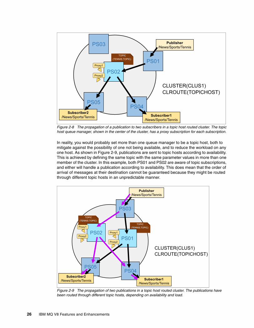
Figure 2-8 The propagation of a publication to two subscribers in a topic host routed cluster. The topic host queue manager, shown in the center of the cluster, has a proxy subscription for each subscription.
In reality, you would probably set more than one queue manager to be a topic host, both to mitigate against the possibility of one not being available, and to reduce the workload on any one host. As shown in Figure 2-9, publications are sent to topic hosts according to availability. This is achieved by defining the same topic with the same parameter values in more than one member of the cluster. In this example, both PS01 and PS02 are aware of topic subscriptions, and either will handle a publication according to availability. This does mean that the order of arrival of messages at their destination cannot be guaranteed because they might be routed through different topic hosts in an unpredictable manner.
Figure 2-9 The propagation of two publications in a topic host routed cluster. The publications have been routed through different topic hosts, depending on availability and load.
Publisher/News/Sports/Tennis
TOPIC(TENNIS.TOPIC)
PS03
PS04
PS01
PS02
PS05
Subscriber1/News/Sports/Tennis
Subscriber2/News/Sports/Tennis
CLUSTER(CLUS1)CLROUTE(TOPICHOST)
Proxy1
Proxy2
TOPIC(TENNIS.TOPIC)
TOPIC(TENNIS.TOPIC)
PS04PS05
Subscriber1/News/Sports/Tennis
Subscriber2/News/Sports/Tennis
PS03
Publisher/News/Sports/Tennis
PS01PS02
CLUSTER(CLUS1)CLROUTE(TOPICHOST)
Proxy1
Proxy2Proxy1
Proxy2
26 IBM MQ V8 Features and Enhancements

In a direct routed cluster, channels are established between all queue managers in the cluster, even those members of the cluster that are not involved in either subscribing or publishing. Clearly, the number of connections increases exponentially as queue managers are added to the cluster, which can be a problem if many queue managers are in the cluster.
With topic host routing, by contrast, you can accommodate bigger clusters of queue managers because channels are easier to configure between host queue managers, and proxy subscriptions are created only in those queue managers that define the topic object.
However, this might mean that you must plan carefully. Those queue managers that act as “hubs” must have sufficient resources available to handle the workload. They should also form a stable part of the cluster and not be in a component that might be removed at any time.
2.3 Comparison of topologies
Should you use a hierarchy, a direct cluster, or a topic-host cluster?
Each topology has potential benefits because each is suitable in different situations. One solution might work in several situations, but its success will depend on several factors:
� Number of queue managers in the topology
� Nature of those queue managers (including their capacity, availability, lifetime, and inter connectivity)
� Number and lifetime of subscriptions and of individual topic strings
� Amount of publication traffic
� Distribution pattern of publications in relation to subscribers
Because of the number of variables involved, different solutions might be the most effective in various situations. Consider the following factors when you decide how to implement publish/subscribe
� Scaling� Availability� Publication flows� Configuration
2.3.1 Scaling
A topic host routed cluster is efficient in that subscription knowledge is shared only with the topic host queue managers and such a cluster scales relatively easily. With this topology, you are also potentially saving resources, such as proxy subscriptions, but you are also routing everything through one, or a few, queue managers.
Therefore, carefully assess the sizing requirements of those topic host queue managers to ensure that they can handle the required load. Full repository queue managers should remain dedicated to that function and not be made into topic hosts also.
A topic host queue manager should not host application connections in order to keep isolated IBM MQ administrative and maintenance tasks from application changes and updates.
By contrast, direct routed clusters share subscription knowledge across all queue managers and the amount of such information being shared tends to increase exponentially. This can be a concern for large clusters and can restrict their maximum size.
Chapter 2. Topic host routed publish/subscribe 27
This means that in a direct routed cluster, many queue manager channels must be established, even to queue managers with no publishers or subscribers; channel connectivity is restricted in a topic host routed cluster.
Channel connectivity is also restricted in a hierarchy. Although subscription knowledge is shared throughout the hierarchy, direct connections are made only between parent and child queue managers.
2.3.2 Availability
A direct routed cluster is robust in that if an individual queue manager becomes unavailable, only the publishers and subscribers on that queue manager are affected.
Generally, the same applies to a topic host routed cluster unless the unavailable queue manager hosts topic definitions, in which case potentially many publishers and subscribers can be affected. However, this situation can be avoided by having two or more topic hosts in the cluster that can share topic definitions.
Availability in a hierarchy can be a problem; if the unavailable queue manager represents a node in the tree that has children, many other queue managers might be affected, because a whole branch of the tree might be blocked.
2.3.3 Publication flows
In a direct routed cluster, there is typically a direct connection from the queue manager where the publication was put on a queue to the subscriber’s queue manager. This direct communication therefore tends to be the fastest.
By contrast, to deliver a publication in a topic host routed cluster can take two steps: from publisher to topic host, and then on to subscriber. But that can sometimes be offset by putting dominant publishers or subscribers on the same queue managers as topic hosts.
In terms of publication flow, a hierarchy is often the worst option, with publications having to travel between queue managers as they move up the branches of the hierarchy and back down to the subscriber’s queue manager. Again, this can often be minimized by carefully planning the structure of the hierarchy to ensure major publications take the shortest path between publishers and subscribers.
2.3.4 Configuration
Hierarchies require careful planning and configuration; each queue manager must define its parent in the hierarchy. Because each queue manager is closely tied to its neighbors in the topic tree, you might have to reconfigure several individual queue managers if you alter the hierarchy.
By contrast, after the overall configuration of a cluster is defined, queue managers can be added and removed without much extra work. In particular, a direct routed cluster requires relatively little configuration, needing fewer administrative tasks to get publish/subscribe to be operational. However, with topic host routing, you must be careful when adding and removing topic hosts.
28 IBM MQ V8 Features and Enhancements

2.3.5 Comparison summary
The following list summarizes the factors to consider when comparing topologies:
� Scaling: Topic host routing is often the best option when clusters become large because the configuration of extra queue managers is minimal and, unlike, direct routing, each queue manager does not need to know about every other queue manager.
� Availability: Clusters (either type of routing) are the best option because they can be configured to compensate for queue managers becoming unavailable.
� Publication performance: All topologies use similar techniques to transfer messages between queue managers, and each can be designed to minimize routes. However, direct routing in a cluster always gives the shortest path, whereas a hierarchy usually involves the longest paths.
� Configuration: Clusters are usually the best option because they are the simplest and most dynamic solution, especially where clusters are already in use.
2.4 Performance tips
Consider the following performance tips:
� Be careful when you select which queue managers to use as topic hosts because after, any changes in configuration or any maintenance will need more planning.
� If clustered publish/subscribe functionality is not needed, you can disable it by the using the MQSC ALTER QMGR PSCLUS(DISABLED) command on each queue manager that is not required to use publish/subscribe functions in a cluster. By doing this, all sharing of publish/subscribe information between queue managers connected through a cluster is prevented. (Normal clustering function continues unchanged.)
� Limiting the subscription scope to a queue manager stops proxy subscriptions from being forwarded to other queue managers in the publish/subscribe topology. This prevents the amount of publish/subscribe messaging information flowing between queue managers when it is not necessary.
� Be sure that the cluster channels are optimized before a new clustered topic is declared. When the topic is created, it will connect with all cluster members to share this knowledge.
� Check that proxy subscriptions are where you expect them to be. This chapter provides examples of how this can be done from either a command prompt or by using the MQ Explorer GUI, by navigating to subscriptions on each queue manager and displaying their properties.
� It is possible in topic host routed configurations to reduce the number of steps taken by publications between queue managers by attaching publishers to the queue managers that hold the topic definition and have remote subscriptions, in order to go directly to the proxy subscriptions. Alternatively, if you have many remote publishers, you can attach subscriptions to the topic hosts thereby reducing the amount of subscription knowledge propagation in the network.
� Setting the parameter PUB to DISABLED in its topic object will quiesce publication traffic through clustered topics. You should typically do this before you add or remove a topic from a cluster, or even do other administrative activities on that queue manager.
See the “Special handling for the PUB parameter” topic of “Multiple cluster topic definitions of the same name” in the MQ V8 Planning section of IBM Knowledge Center:
http://www.ibm.com/support/knowledgecenter/SSFKSJ_8.0.0/com.ibm.mq.pla.doc/q005240_.htm
Chapter 2. Topic host routed publish/subscribe 29

2.5 Problem determination
If you encounter problems when setting up publish/subscribe in a clustered topology, you can check several areas. Also see the “Routing for publish/subscribe clusters: Notes on behavior” topic in the MQ V8 Troubleshooting section of IBM Knowledge Center:
http://www.ibm.com/support/knowledgecenter/SSFKSJ_8.0.0/com.ibm.mq.tro.doc/q005481_.htm
Check the topic object definitionIs the topic object definition configured as expected?
Check cluster topicsUse the following MQSC command to check cluster topics:
DISPLAY TCLUSTER(*) ALL
Check that the topic is reported on at least the following queue managers: topic host queue manager, all the full repositories, and the publishing and subscribing queue managers.
In each case, check the settings for these properties:
� The CLROUTE property is set as you expected.
� The CLSTATE property is set to ACTIVE. If it set to PENDING, INVALID, or ERROR, investigate further.
Check cluster queue managersUse the following MQSC command to check that topic-hosting queue managers are aware of all other queue managers; check that the queue managers are at Version 8:
DISPLAY CLUSQMGR(*) VERSION
Check topic tree nodesUse the following MQSC command to check the topic tree nodes:
DISPLAY TPSTATUS(*) ALL
Check attributes such as CLUSTER, CLROUTE, SUBSCOPE, and PUBSCOPE, to confirm that they are as you expect and that they match the topic configuration. If they don’t, check whether there is another topic object that is overriding the expected values, remembering that topic objects inherit behavior from topic nodes higher in the tree, which can affect how topics lower down behave.
Check proxy subscriptionsUse the following MQSC command to check your proxy subscriptions and that they are where you expect them to be:
DISPLAY SUB(*) SUBTYPE(PROXY)
Note the format of the topic host routed subscription name:
SYSTEM.PROXY_2.topic_object_name cluster_name origin_qmgr topic_string
Missing proxy subscriptions might indicate one of the following problems:
� Your application is not subscribing on the correct topic object or topic string.� There is a problem with the topic definition.� A channel is not running or is not configured correctly.
30 IBM MQ V8 Features and Enhancements

See also the “Checking proxy subscription locations” topic in the MQ V8 Troubleshooting section of IBM Knowledge Center:
http://www-01.ibm.com/support/knowledgecenter/SSFKSJ_8.0.0/com.ibm.mq.tro.doc/q005484_.htm
Check for indications that messages have been sentUse the following MQSC command to check for traces of message flow:
DISPLAY SBSTATUS(subscription_name) NUMMSGS
Check the value of the NUMMSGS parameter of a subscription. This gives an indication of the number of publications that have matched this subscription and have been sent to the queue manager that is the target of the proxy subscription.
Check the channel and system queue status
Check the system error logsCheck for this information:
� Errors that directly relate to clustered publish/subscribe.� Errors that relate to clustering in general.� Errors that relate to channels.
Check channel statusCheck that channels between queue managers are functioning correctly.
Check system queuesWhen the system is running normally, expect the following system queues to remain empty:
� SYSTEM.INTER.QMGR.PUBS
Publications arriving from remote queue managers
� SYSTEM.INTER.QMGR.FANREQ
Requests to send proxy subscriptions
� SYSTEM.INTER.QMGR.CONTROL
Requests from other queue managers to register proxy subscriptions
� SYSTEM.CLUSTER.TRANSMIT.QUEUE (or any other transmission queue involved)
All inter-queue manager outbound messages
For hierarchies, these are the queues:
� SYSTEM.BROKER.CONTROL.QUEUE
Requests to register and deregister subscriptions
� SYSTEM.BROKER.DEFAULT.STREAM
Publications arriving from remote queue managers and from local ‘queued’ publish/subscribe applications
� SYSTEM.BROKER.INTER.BROKER.COMMUNICATIONS
Requests from other queue managers in the hierarchy
If problems exist, messages can accumulate on system queues. This might be because the system is producing messages too quickly or because an error has occurred. Determine whether messages are still being processed, albeit slowly, or whether no messages are being processed at all.
Chapter 2. Topic host routed publish/subscribe 31

32 IBM MQ V8 Features and Enhancements

Chapter 3. User authentication
This chapter shows how to use authentication features that are new in MQ V8. It covers how an administrator configures the capabilities, and how an application developer uses the various provided interfaces. For applications that cannot be changed, there is discussion of a channel security, exit which can supply the necessary credentials on the application’s behalf.
This chapter contains the following topics:
� 3.1, “Introduction to authentication” on page 34� 3.2, “Identity repositories” on page 34� 3.3, “Relationship to authorization” on page 35� 3.4, “Administration for authentication” on page 35� 3.5, “Application programming for authentication” on page 39� 3.6, “JMS and XMS” on page 40� 3.7, “XA Transaction managers” on page 41� 3.8, “Relationship to CHLAUTH rules” on page 41� 3.9, “Using the mqccred channel security exit” on page 41� 3.10, “Password protection on the network” on page 43� 3.11, “Using authentication in programs provided by MQ” on page 43� 3.12, “Solving authentication failures” on page 44� 3.13, “Summary” on page 46
Chapter 10, “Authentication scenarios” on page 177 contains detailed configurations and various demonstrations of the information that is described here (in Chapter 3).
For an extended discussion of authentication and authorization concepts, and the relationship between them, see Secure Messaging Scenarios with WebSphere MQ, SG24-8069. Although that book was written before the authentication capabilities of MQ V8 were introduced, it is still relevant.
3
© Copyright IBM Corp. 2014. All rights reserved. 33

3.1 Introduction to authentication
Authentication is the process of verifying that someone really is who that person claims to be. There are many mechanisms for carrying out authentication, but the traditional approach, and the one now supported by IBM MQ, is by checking a password.
3.1.1 IBM MQ history
For many years, MQ did not do direct authentication of users. Although there were opportunities for channel exits to perform authentication, these were not supplied with the product for most platforms. Exceptions included amqrspin (Kerberos) for Windows and CSQ4BCX3 for z/OS. There was no mechanism for authentication of local users. Instead, the assumption was that the operating system had carried out authentication when the user logged on, and MQ simply picked up the user ID that was running the application and used that without further checks. Although some additional steps were done when running applications or transactions inside environments such as CICS, the concept was still to use a user ID that was directly associated with the program.
MQ V6 extended the MQI to allow applications to explicitly put a user ID and password in the parameters to the MQCONNX verb, and Java Message Service (JMS) has a form of the connection method where user ID and password information is supplied. But even with those function calls, the queue manager did no real checking of the values. Additional exit points for the Authorization Service were created to make it possible to authenticate local users and not just clients. That, however, still relied on someone writing code to execute at those exit points.
Instead, the only authentication carried out was for TLS/SSL channels, where a certificate was validated. Again, the basic assumption was that only the “correct” user was able to access a certificate. And then given the certificate, MQ provided ways (for example on z/OS through IBM RACF® services and then later on all platforms, with CHLAUTH rules) to map the inbound certificate to a user ID or identity.
With V8, doing true authentication of users is possible. The identity used for authorization, which is also the identity carried in a message descriptor (MQMD), might be completely unrelated to the user ID running the application.
3.2 Identity repositories
On all platforms, MQ integrates with the local operating system (OS) user repository. So on Windows, a Windows account can be verified; on UNIX, it is someone defined to that machine; on z/OS, it is a user ID defined in RACF or other external security manager.
All of these operating systems have mechanisms to transparently “extend” their view of which users are defined beyond local definitions. For example, on UNIX systems, configuration through files such as /etc/nsswitch.conf can be used to refer to identities defined in a Network Information System (NIS) or LDAP server. Because these are handled directly by the OS services, MQ is unaware of their existence, and works with them just as though the users are defined in /etc/passwd. These users are therefore always considered to be OS-defined.
On distributed platforms, MQ now can also directly access an LDAP server to verify users and their passwords. This allows user IDs and passwords to be defined independently of an operating system, in a central repository.
34 IBM MQ V8 Features and Enhancements

3.3 Relationship to authorization
At the end of a successful authentication process, an identity has been obtained. That identity might be the same as the one given as the user ID in the connection request, or it might be derived from other mechanisms. This chapter shows how that final identity is chosen. However, after this identity is selected, it is used for approving all of the application’s requests to access resources such as queues.
Commands such as setmqaut or rules in the z/OS security manager (for example RACF) define these access lists. Regardless of how the connection is authenticated, the identity must be known to these authorization managers. For distributed platforms, that means that the identity must be a locally known user ID so that checks on group membership can be made, even if the authentication was done in an LDAP server.
The identity associated with the connection is visible through commands such as DISPLAY CONN, so you can check what authorizations are required.
This identity is also used to fill in the MQMQD user identifier field when messages are put, and can then be used on remote systems for authorization checks, for example when PUTAUT(CTX) is configured, or for some types of report messages.
3.4 Administration for authentication
The first step needed to carry out authentication is to enable the capability on the queue manager.
This is done with two definitions, one on an AUTHINFO object and one on the QMGR object. There are several subtypes for the AUTHINFO object, two of which are used for defining how certificates are validated (OCSP and CRLLDAP) and two of which are associated with password authentication (IDPWOS and IDPWLDAP).
The two password-related subtypes correspond to the two repositories available for MQ to use: the operating system or LDAP. Parameters on these object definitions tell the queue manager more details about the authentication process.
After an AUTHINFO object is defined with the required values, the QMGR object definition must be changed to point at that AUTHINFO object by setting the CONNAUTH attribute. Finally, these values are made active by issuing the REFRESH SECURITY TYPE(CONNAUTH) command.
No direct way exists to determine whether changes to the AUTHINFO or QMGR definitions were made but are not currently active; always ensure that the REFRESH SECURITY command is executed immediately after making the other changes. If refreshing is not done, the changes are effective only after the next queue manager restarts. On z/OS, information is written to the queue manager job log to show the current values of some of the authentication parameters but not all.
3.4.1 AUTHINFO objects
The IDPWOS and IDPWLDAP types of AUTHINFO tell the queue manager how to perform the authentication. The simplest mechanism is for the operating system method and the default values are often sufficient. Several attributes of these AUTHINFO objects are common, and behave the same for both subtypes of the object.
Chapter 3. User authentication 35

Figure 3-1 is a summary of the attributes available for the IDPWOS and IDPWLADP AUTHINFO subtypes. At the time of writing this book, the IBM Knowledge Center documentation was missing some of this information, so it is shown here as reference.
Figure 3-1 Summary of defining authentication subtypes in MQSC format
Core attributesThe following CHCKLNT and CHCKLOCL values specify how authentication is to be done for client connections and local applications.
� If set to REQUIRED, all connections through that route must provide a password.
� If set to REQDADM, connections that assert an “MQ administrator” account must provide a password, but other applications do not need to provide a password. The definition of “administrator” varies by platform, but means the same as the *MQADMIN pseudo-account used on CHLAUTH rules. So it corresponds to any UNIX user who is in the mqm group, or a Windows user who is in the mqm group or in the Administrators group, and so on. Then, for non-administrative users, providing a password is optional. This option is available only on distributed platforms, and is not on z/OS.
� If set to OPTIONAL, a password is not needed but will be verified if supplied.
� If set to NONE, no authentication is done, even if a password is given from the application. The user ID is also ignored regardless of the ADOPTCTX setting.
DEFINE AUTHINFO(name) AUTHTYPE(IDPWOS) LIKE(name) DESCR(description)CHCKCLNT(NONE|OPTIONAL|REQDADM|REQUIRED)CHCKLOCL(NONE|OPTIONAL|REQDADM|REQUIRED)ADOPTCTX(YES|NO)FAILDLAY(n)
DEFINE AUTHINFO(name) AUTHTYPE(IDPWLDAP) LIKE(name) DESCR(description)CHCKCLNT(NONE|OPTIONAL|REQDADM|REQUIRED)CHCKLOCL(NONE|OPTIONAL|REQDADM|REQUIRED)ADOPTCTX(YES|NO)FAILDLAY(n) LDAPUSER(user)LDAPPWD(password)CONNAME(address of LDAP server)SECCOMM(YES|NO|ANON)SHORTUSR(LDAP attribute - mandatory)USRFIELD(LDAP attribute - optional)BASEDNU(Distinguished Name suffix)CLASSUSR(Object class in LDAP server)
Notes: REQDADM not available on z/OSCMDSCOPE and QSGDISP options available for z/OS as usualREPLACE/NOREPLACE available as usual
IDPWLDAP subtype not available for z/OS
36 IBM MQ V8 Features and Enhancements
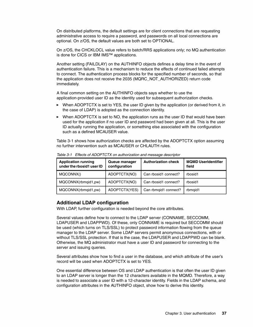
On distributed platforms, the default settings are for client connections that are requesting administrative access to require a password, and passwords on all local connections are optional. On z/OS, the default values are both set to OPTIONAL.
On z/OS, the CHCKLOCL value refers to batch/RRS applications only; no MQ authentication is done for CICS or IBM IMS™ applications.
Another setting (FAILDLAY) on the AUTHINFO objects defines a delay time in the event of authentication failure. This is a mechanism to reduce the effects of continued failed attempts to connect. The authentication process blocks for the specified number of seconds, so that the application does not receive the 2035 (MQRC_NOT_AUTHORIZED) return code immediately.
A final common setting on the AUTHINFO objects says whether to use the application-provided user ID as the identity used for subsequent authorization checks.
� When ADOPTCTX is set to YES, the user ID given by the application (or derived from it, in the case of LDAP) is adopted as the connection identity.
� When ADOPTCTX is set to NO, the application runs as the user ID that would have been used for the application if no user ID and password had been given at all. This is the user ID actually running the application, or something else associated with the configuration such as a defined MCAUSER value.
Table 3-1 shows how authorization checks are affected by the ADOPTCTX option assuming no further intervention such as MCAUSER or CHLAUTH rules.
Table 3-1 Effects of ADOPTCTX on authorization and message descriptor
Additional LDAP configurationWith LDAP, further configuration is needed beyond the core attributes.
Several values define how to connect to the LDAP server (CONNAME, SECCOMM, LDAPUSER and LDAPPWD). Of these, only CONNAME is required but SECCOMM should be used (which turns on TLS/SSL) to protect password information flowing from the queue manager to the LDAP server. Some LDAP servers permit anonymous connections, with or without TLS/SSL protection. If that is the case, the LDAPUSER and LDAPPWD can be blank. Otherwise, the MQ administrator must have a user ID and password for connecting to the server and issuing queries.
Several attributes show how to find a user in the database, and which attribute of the user’s record will be used when ADOPTCTX is set to YES.
One essential difference between OS and LDAP authentication is that often the user ID given to an LDAP server is longer than the 12 characters available in the MQMD. Therefore, a way is needed to associate a user ID with a 12-character identity. Fields in the LDAP schema, and configuration attributes in the AUTHINFO object, show how to derive this identity.
Application running under the rbosid1 user ID
Queue manager configuration
Authorization check MQMD UserIdentifier field
MQCONNX() ADOPTCTX(NO) Can rbosid1 connect? rbosid1
MQCONNX(rbmqid1,pw) ADOPTCTX(NO) Can rbosid1 connect? rbosid1
MQCONNX(rbmqid1,pw) ADOPTCTX(YES) Can rbmqid1 connect? rbmqid1
Chapter 3. User authentication 37

Obtaining a short name from LDAPA typical user record in an LDAP server looks something like this:
DN=cn=Application Rbmqid1,ou=users,o=ibm,[email protected]=Rbmqid1phone=123456password=******
The distinguished name (DN) is the unique record identifier; all entries in the database must have a different DN. The user record will be an instance of a class; all records in the same class have the same fields available. Not all fields in a class are always defined; some fields are optional.
To authenticate an LDAP identity, MQ must be configured to know where to look in the database to find these identity records. This means that the MQ administrator must have an understanding of the LDAP schema that is being used in the organization. This information may be documented and generally available within the enterprise, or it might require a conversation between the MQ administrator and the LDAP administrator.
� The BASEDNU value in the AUTHINFO definition is set to the common set of elements in the DN shared by all users. For this example, BASEDNU must be set as follows:
“ou=users,o=ibm,c=gb”
� The CLASSUSR value is set to the class associated with this type of record. If not explicitly set, a default class of inetOrgPerson is used (and is often used for user records).
A further pair of definitions tells MQ how to find the specific record for the user, and how to extract an identity that will be used for subsequent authorization and to fit into the limit of 12 characters in the MQMD UserIdentifier field.
� USRFIELD is the attribute of the record that the application will usually provide as the user ID in the MQCSP structure. This is an optional attribute in the AUTHINFO definition; if left blank, then the queue manager uses the SHORTUSR value for the search.
� SHORTUSR is the attribute whose value must be no more than 12 characters long. This is a mandatory attribute in the AUTHINFO definition. If ADOPTCTX is set to YES, then the value of this field in the user record is used for authorization.
A typical enterprise environment might require users to authenticate their access to services by using their email address as their unique identity. In such a system, the queue manager is configured with USRFIELD(‘mail’) SHORTUSR(‘id’).
An MQ application then has several choices about what user ID to specify during the connection, all of which have the same result:
� An unqualified user ID (for example [email protected]). The queue manager looks for a record where this is the value of the mail attribute for a user.
� A single-field qualified user ID (for example [email protected] or phone=123456). Because the application has told the queue manager which field to search for, the USRFIELD is not relevant here. Any field in the record can be used. Provided that a search of the LDAP database returns a unique record, the password can be checked. If several people shared the same phone number, then the authentication process fails.
� A fully qualified distinguished name (for example, cn=Application Rbmqid1,ou=users,o=ibm,c=gb). This is always a unique entry in the database, but it is longer than many users might like to type if the application requires interactive authentication.
38 IBM MQ V8 Features and Enhancements

Assuming a correct password was given and ADOPTCTX is YES, the connection will be associated with the Rbmqid1 identity, and all authorization checks will work with that.
On UNIX systems, the short user is converted to all lowercase (rbmqid1), corresponding to the mechanism used with the MQMD when messages arrive across a channel.
3.4.2 Simple example
Example 3-1 shows the basic steps required to get a queue manager to authenticate user IDs. The default attribute values are all that is required here. More examples are included in Chapter 10, “Authentication scenarios” on page 177.
Example 3-1 Configuring a queue manager for authentication
DEFINE AUTHINFO(RB.IDPWOS) AUTHTYPE(IDPWOS) 1 : DEFINE AUTHINFO(RB.IDPWOS) AUTHTYPE(IDPWOS)AMQ8563: WebSphere MQ authentication information object created.DISPLAY AUTHINFO(RB.IDPWOS) 2 : DISPLAY AUTHINFO(RB.IDPWOS)AMQ8566: Display authentication information details. AUTHINFO(RB.IDPWOS) AUTHTYPE(IDPWOS) ADOPTCTX(NO) DESCR( ) CHCKCLNT(REQDADM) CHCKLOCL(OPTIONAL) FAILDLAY(1) ALTDATE(2014-06-09) ALTTIME(11.29.10)ALTER QMGR CONNAUTH(RB.IDPWOS) 3 : ALTER QMGR CONNAUTH(RB.IDPWOS)AMQ8005: WebSphere MQ queue manager changed.REFRESH SECURITY TYPE(CONNAUTH) 4 : REFRESH SECURITY TYPE(CONNAUTH)AMQ8560: WebSphere MQ security cache refreshed.
3.5 Application programming for authentication
The programming interfaces for setting the user ID and password information to applications depend on which API the application is using.
3.5.1 MQI
For an application developer using MQI, the only change that is needed is to use the correct parameters when connecting to the queue manager. In the procedural languages such as C, this means using the MQCONNX verb instead of MQCONN, and filling in the MQCSP structure. Example 3-2 on page 40 shows a fragment of C code used to connect to a queue manager.
Chapter 3. User authentication 39

Example 3-2 Authenticating a connection using C
char *QMName = “QM1”;char *Userid = “rbmqid1”;char *Password = “passw0rd”;
MQCNO cno = {MQCNO_DEFAULT}; MQCSP csp = {MQCSP_DEFAULT};
...
cno.SecurityParmsPtr = &csp;cno.Version = MQCNO_VERSION_5;
csp.AuthenticationType = MQCSP_AUTH_USER_ID_AND_PWD;csp.CSPuser IDPtr = Userid;csp.CSPuser IDLength = strlen(Userid);
csp.CSPPasswordPtr = Password;csp.CSPPasswordLength = strlen(csp.CSPPasswordPtr);
MQCONNX(QMName, &cno, &Hcon, &CompCode, &CReason);
For the object-oriented languages, such as the Java classes, properties are set before connecting to the queue manager. Example 3-3 shows a fragment of Java code used to connect to a queue manager. The MQEnvironment class can also be used instead of the hash table.
Example 3-3 Authenticating a connection using Java
String QMNAme = “QM1”;String Userid = “rbmqid1”;String Password = “passw0rd”;
Hashtable h = new Hashtable();h.put(MQConstants.USER_ID_PROPERTY, Userid);h.put(MQConstants.PASSWORD_PROPERTY, Password);h.put(MQConstants.USE_MQCSP_AUTHENTICATION_PROPERTY, true);
MQQueueManager qMgr = new MQQueueManager(QMName,h);
3.6 JMS and XMS
A form of the JMS (and hence XMS) connection methods takes user ID and password parameters, as in the following example:
connectionFactory.createConnection(Userid,Password)
No further changes are needed.
40 IBM MQ V8 Features and Enhancements

3.7 XA Transaction managers
The XAOpenString definition tells an XA transaction manager how to connect to resource managers such as databases or queue managers. Every resource manager has its own format, to give product-specific connection and control information.
With MQ V8, the format of this string has been extended to permit a user ID and password to be supplied with the uid and pwd attributes. The following example string configures a client connection to a queue manager:
channel=TO.QMRB,trptype=tcp,conname=qmrb,qmname=QMRB,uid=mquser,pwd=passw0rd
This string must be put in a transaction manager’s configuration; it is not an MQ attribute for a file such as the qm.ini file.
3.8 Relationship to CHLAUTH rules
A further level of granular control can be applied to client channels, allowing some channels to have more stringent CHCKCLNT behavior than is configured in the AUTHINFO object. This might be useful, for example, when only one particular client channel is meant to be used for administrative access. In addition to rules, such as allowing only certain IP addresses to connect to this channel, a useful step might be to force password checking here, regardless of the behavior of other client channels. For each CHLAUTH rule, a CHCKCLNT option is available that can override the AUTHINFO setting for the queue manager. By default, the value in a CHLAUTH rule is ASQMGR, but it can be set to REQUIRED or REQDADM and that applies only to the connections affected by this rule.
Another aspect of these rules is the ability to match an asserted user ID against a filter. In a USERMAP rule, the user ID presented by the client application in the MQCSP structure is the value checked.
3.9 Using the mqccred channel security exit
Adding the user ID and password parameters to some application programs might not be immediately possible. For client programs, IBM MQ V8 supplies a channel security exit that can automatically insert these values during the connection process. That means that the only change necessary is the definition of the client channel, and not the application code.
To use this, the mqccred exit must be configured as the security exit on a client channel as shown in Example 3-4.
Example 3-4 MQSC definition to invoke the mqccred exit
DEFINE CHL(TO.QM1) CHLTYPE(CLNTCONN) + CONNAME(‘server1’) + SCYEXIT(‘mqccred(ChlExit)’) + QMNAME(QM1)
This exit reads a configuration file that contains the user ID and password information for queue managers. By default, this file is in the following locations:
� On UNIX: $HOME/.mqs/mqccred.ini � On Windows: c:\Users\<username>\.mqs\mqccred.ini
Chapter 3. User authentication 41

Alternative locations can be named by setting the MQCCRED environment variable.
To set the configuration for a queue manager, add a stanza to this configuration file giving the queue manager name, the user ID and the password. Example 3-5 shows a configuration file after the information for QM1 is added.
Example 3-5 Channel exit configuration file
AllQueueManagers:User=defuser
Force=FALSE
QueueManager:Password=passw0rd
Name=QM1 User=rbmqid1
Keeping plain text passwords in configuration files such as this is not a good practice. Therefore, a tool is provided to give an additional layer of protection. The runmqccred program modifies this configuration file, and replaces the password with an obfuscated version. Example 3-6 shows the updated version of the file.
Example 3-6 Channel exit configuration file after running runmqccred
AllQueueManagers:User=defuser
Force=FALSE
QueueManager:OPW=44925E70E7B733BAName=QM1
User=rbmqid1
Further protection is also applied. Both the runmqccred program and the mqccred exit require, by default, that the configuration file is not accessible to other users on the system. The exit also requires that no unprotected passwords are in the file. These protection checks can be overridden for the exit by setting NOCHECKS in the SCYDATA attribute for the channel. The exit also supports putting DEBUG or ERROR in the SCYDATA field, which causes it to print information to stdout as it executes.
Protection: The configuration file used by the exit must be locked using operating system privileges. On UNIX, the file must not have group or other access; on Windows, the check is whether access has been granted to the Everyone, Guests, or Others groups. This is to make it difficult for other people on the machine to read the file. The password contained in the file is obfuscated, making it difficult to reverse directly, but it is not using a high-strength cryptographic algorithm. If other people can read the file, they may be able to extract the passwords; operating system privileges are an additional layer of protection.
42 IBM MQ V8 Features and Enhancements

3.10 Password protection on the network
Normally, the recommendation is that network connections for MQ be protected using TLS/SSL protocols. The various CipherSuites encrypt all of the flowing data, ensuring that it cannot be viewed or modified as it goes through the network. This includes any password information that is sent to authenticate a client application.
However, not everyone uses this level of control for clients. To provide a degree of security, the IBM MQ V8 clients and queue managers cooperate to protect the password information as it flows. A network sniffer cannot then see plain text passwords on the wire. This protection is not as strong as using TLS/SSL, but no configuration is needed to enable it.
By default, this happens automatically, but it can be overridden. The PasswordProtection attribute in the Channels stanza of the qm.ini or mqclient.ini files controls the behavior. Possible values of this attribute are as follows:
� COMPATIBLE (the default if not specified): This allows passwords to be sent in plain text but only when communicating with MQ 7.5 or earlier. When communicating with an MQ 8 partner, password protection will be used unless an TLS/SSL is also configured for the channel.
� ALWAYS For an MQ 8 client, MQ never sends a password to the remote system unless the connection is using TLS/SSL encryption or the remote queue manager supports password protection. For an MQ 8 queue manager, MQ never accepts an inbound client connection unless it is using TLS/SSL encryption or the client supports password protection.
Not all TLS/SSL CipherSuites encrypt data; consider this when you determine whether to use the password protection feature. Also, to reiterate, this feature works only when both ends of the connection are at MQ V8. Older versions of MQ do not support this password protection capability and TLS/SSL is therefore the only way to hide passwords flowing across the network.
3.11 Using authentication in programs provided by MQ
The MQ product contains many programs that users run directly. This includes administrative programs such as runmqsc and sample programs such as amqsput. Many of these programs have been updated to allow a user ID and password to be used.
The sample programsThe most commonly used sample programs are amqsput, amqsget, and amqsbcg. They all can now recognize that authentication is required. The source code for these programs is, of course, still available so that developers can see how easy adding authentication through the MQI is.
These programs look for an environment variable, MQSAMP_USER_ID, and if set, they prompt for a password before continuing. The password is not masked in any way as it is typed but this approach is deliberately simple so that the changes, specific to MQ, are obvious. Real applications need better ways of prompting for or obtaining passwords, but adding more secure password handling is outside the scope of showing how to use IBM MQ.
Note: With the ALWAYS setting you can ensure that passwords are never sent in plain text across a network. It prevents unencrypted connections between MQ 8 and earlier releases; always consider your interoperability needs before you enable this setting.
Chapter 3. User authentication 43

Administration programsEssential administration programs were also updated to work with user IDs and passwords. This is needed because of the possibility of setting CHCKLOCL to REQUIRED or REQDADM; without a user ID option, even runmqsc fails to connect.
Commands that were modified include runmqsc, runmqdlq, dspmqrte, dmpmqcfg, and runmqtrm. These all can take a -u user ID option on the command line, and they expect to read a password as the first line of input. The various authority control commands such as setmqaut were not extended, because the same operations can be done directly from runmqsc, for example by using the SET AUTHREC commands.
Some of these commands are often run with their commands coming from a redirected text file. Because the password is also read from stdin, scripts must add the password to the execution of the program. An insecure example for UNIX is as follows:
(echo passw0rd; cat commands.mqsc) | runmqsc -u mqadmin QM1
In a similar fashion for Windows, if the password is held in a file (pw.txt) this can be put in a batch file:
(type pw.txt & type commands.mqsc) | runmqsc -u mqadmin QM1
Joining the commands like this is better than editing the real MQSC script to add a password as the first line, although that works too.
3.12 Solving authentication failures
When a security-related failure occurs during the authentication process, an application is likely to receive one of two return codes:
� MQRC_NOT_AUTHORIZED (2035) normally indicates that the application provided invalid credentials such as a bad password, or tried to use an unrecognized user ID. To solve this, the application program or the person running it must use a correct identity and password. This code might also mean that the application successfully authenticated, but failed a subsequent authorization check.
� MQRC_SECURITY_ERROR (2063) normally indicates an error in configuring the queue manager or a problem connecting to an LDAP server. To solve this, the MQ administrator must correct the configuration.
When failures do occur, deliberately little information is returned to the application beyond the return code. However, more is available to the administrator to monitor and solve failures.
Error logsAlso, several messages are written to the queue manager error logs. Example 3-7 on page 45 shows the messages that correspond to a failed authentication request. Again, some of it might be interesting, but also some is possibly confusing.
Three messages correspond to a single authentication request from a client attempting to connect to the queue manager.
� The first of these messages shows the user ID given by the application in the MQCSP structure.
� The second message gives more information about the queue manager configuration. The following comment is misleading and might be modified in a future V8 fix pack:
because the user ID is privileged
44 IBM MQ V8 Features and Enhancements

In this particular case, the password was checked because it was provided. This error message does not distinguish between whether the user is an administrative user, but it does show whether password verification will happen. In this case, the password will be checked because the CHCKCLNT value is not NONE.
� The final message in the batch happens because this was a client connection, and the channel program (running under the mqm id) was not able to successfully complete the connection.
The three messages are related because they happen with the same time stamp, and the Process value in the message header is identical.
Example 3-7 Error log messages
10/06/14 14:13:15 - Process(24707160.47) User(mqm) Program(amqrmppa) Host(server1) Installation(Installation5) VRMF(8.0.0.0) QMgr(QM1)
AMQ5534: user ID 'rbmqid1' authentication failed
EXPLANATION:The user ID and password supplied by 'mqconn.MQSend' could not beauthenticated.ACTION:Ensure that the correct user ID and password are provided by the application.Ensure that the authentication repository is correctly configured. Look atprevious error messages for any additional information.
-------------------------------------------------------------------------------10/06/14 14:13:15 - Process(24707160.47) User(mqm) Program(amqrmppa) Host(server1) Installation(Installation5) VRMF(8.0.0.0) QMgr(QM1)
AMQ5541: The failed authentication check was caused by the queue managerCONNAUTH CHCKCLNT(REQDADM) configuration.
EXPLANATION:The user ID 'rbmqid1' and its password were checked because the user ID isprivileged and the queue manager connection authority (CONNAUTH) configurationrefers to an authentication information (AUTHINFO) object named'SYSTEM.DEFAULT.AUTHINFO.IDPWOS' with CHCKCLNT(REQDADM).
This message accompanies a previous error to clarify the reason for the user IDand password check.ACTION:Refer to the previous error for more information.
Ensure that a password is specified by the client application and that thepassword is correct for the user ID. The authentication configuration of thequeue manager connection determines the user ID repository. For example, thelocal operating system user database or an LDAP server.
To avoid the authentication check, you can either use an unprivileged user IDor amend the authentication configuration of the queue manager. You can amendthe CHCKCLNT attribute in the CHLAUTH record, but you should generally notallow unauthenticated remote access.-------------------------------------------------------------------------------10/06/14 14:13:15 - Process(24707160.47) User(mqm) Program(amqrmppa) Host(server1) Installation(Installation5) VRMF(8.0.0.0) QMgr(QM1)
Chapter 3. User authentication 45

AMQ9557: Queue Manager user ID initialization failed for 'mqm'.
EXPLANATION:The call to initialize the user ID 'mqm' failed with CompCode 2 and Reason2035.ACTION:Correct the error and try again.
On z/OS, authentication failures are shown in the queue manager job log. The logs might also have entries for the system security manager component. Example 3-8 shows that an unknown user ID is attempting to connect followed by a user ID giving a bad password.
Example 3-8 Queue manager job log on z/OS
ICH408I USER(xxxxxxx ) GROUP( ) NAME(??? ) 901 901 LOGON/JOB INITIATION - USER AT TERMINAL NOT RACF-DEFINEDIRR012I VERIFICATION FAILED. USER PROFILE NOT FOUND. ICH408I USER(TAYLOR ) GROUP(SYS1 ) NAME(MARK TAYLOR ) 906 906 LOGON/JOB INITIATION - INVALID PASSWORD IRR013I VERIFICATION FAILED. INVALID PASSWORD GIVEN.
Event messagesAuthentication failures, like authorization failures on distributed platforms, generate authority event messages when they are enabled for the queue manager. Example 3-9 shows such an event. Although authentication and authorization are different, using a variation of the “not authorized” event helps the monitoring programs more easily handle it. The event, which was formatted here by the MS0P SupportPac extension to the MQ Explorer, shows several interesting factors:
� The reason qualifier shows that this event was caused by the application using the MQCSP structure to provide a user ID and password.
� The real user ID associated with the running program.
� The user ID as given in the MQCSP structure.
� Which program was running
Example 3-9 An event message caused by authentication failure
Events for Queue Manager QM1 SYSTEM.ADMIN.QMGR.EVENT: [2014/06/09 17:09:37 BST] Not Authorized [2035] Event Type : Queue Manager Queue Manager Name : QM1 Reason Qualifier : Csp Not Authorized [29] user IDentifier : root Csp user IDentifier : rbmqid1 Appl Type : Java Appl Name : mqconn.MQSend
3.13 Summary
This chapter introduces the administration and application programming features of IBM MQ V8 that allows the queue manager to authenticate user connections. Many examples are included in Chapter 10, “Authentication scenarios” on page 177.
46 IBM MQ V8 Features and Enhancements

Chapter 4. TLS/SSL Digital Certificate Management
Security is an important consideration for MQ administrators. Transport Layer Security (TLS) and Secure Sockets Layer (SSL) are industry standards that provide technology to assure identity and data privacy. SSL and TLS protocol can be used for MQ client application connections to queue managers or with queue manager-to-queue manager distributed queuing and clustering over the network.
IBM MQ V8 supports Version 3.0 of the SSL protocol and Version 1.0 and Version 1.2 of the TLS protocol. This chapter describes how you can use TLS/SSL security for your MQ implementations and the features available in MQ V8 for channels using TLS/SSL certificates.
This chapter contains the following topics:
� 4.1, “Basic security concepts” on page 48
� 4.2, “Multiple certificates and names for digital certificates” on page 50
� 4.3, “The CERTLABL parameter” on page 51
� 4.4, “Using SSLCERTI to ensure the correct certificate is used” on page 55
� 4.5, “Scenario and examples to enable TLS/SSL digital certificates on channels” on page 59
� 4.6, “Additional TLS/SSL improvements across platforms” on page 69
4
© Copyright IBM Corp. 2014. All rights reserved. 47

4.1 Basic security concepts
The assumption in this book is that readers are familiar with security features in previous MQ versions so this section provides only a high level overview of security topics. If you need further information about IB MQ security features and how to implement them, see Secure Messaging Scenarios with WebSphere MQ, SG24-8069.
Basic information is required before you prepare secure interconnected scenarios for IBM MQ configurations. You should recognize the difference between authorization and authentication. Chapter 3, “User authentication” on page 33 describes these topics.
� Authentication verifies and validates that an entity is who they claim to be (for example, by checking certificate information).
� Authorization is a method for MQ to allow (or restrict) access, normally through the object authority manager (OAM), thereby determining which entities are allowed to access MQ objects for actions such as connect, get, put and so forth.
This chapter has more information about ways to authenticate user connectivity to MQ via channel connections.
In MQ V8, locally bound applications or clients can now supply an ID and password credentials to be checked, as explained in Chapter 3, “User authentication” on page 33.
The connection security parameters structure (MQCSP) can be specified on an MQCONNX call and enables the authorization service to authenticate a user ID and password provided by the application. If an MQCSP is not supplied, when an application connects in “bindings mode” the connection relies on the OS process ID (PID) for authentication and identity. The associated PID is the process that is running the channel rather than running the remote entity so in some cases that might be the mqm ID.
MQ can resolve the credentials from a remote connection to an ID that the queue manager uses to check against the OAM. To do this, the CHLAUTH rule maps the remote ID to a local user ID that is defined on the OS, where the queue manager is running. The resolved ID is used as the channel’s MCAUSER attribute when the channel starts; that ID is subsequently used for authorization checks.
To ensure that the remote user is a trusted ID, IBM MQ allows authentication through TLS/SSL cipher specifications (CipherSpecs) on these channel connections as a means of authenticating the user. Further, the SSLPEER and SSLCERTI parameters can allow or block connections based on fields in the certificate. Rather than writing security exits for the channels, CHLAUTH rules can be implemented to filter inbound connection requests. The certificate provides both a Subject distinguished name and an Issuer distinguished name. The SSLPEER filters match against the identity of the certificate owner, which is found in the Subject distinguished name while the SSLCERTI checks for a match with the identity of the certificate issuer (certificate authority, or CA), which is in the Issuer distinguished name. The CHLAUTH can also check the QMGR name, UserID, or IP address.
For distributed platforms, Global Secure Toolkit (GSKit) V8.0 is integrated with IBM MQ V8. In GSkit v8.0, the iKeyman command accepts any element of the DN, or a form of the subject alternative name (SAN). It does not mandate that you provide it with a common name. Therefore, applications that search for a certificate must not assume that a certificate has a common name.
48 IBM MQ V8 Features and Enhancements
TLS/SSL digital certificate authentication occurs when an X.509 certificate is presented during connection. The handshake procedure assures that the requestor holds the private key to the certificate presented. For more information about the SSL or TLS handshake, see the following web page:
http://www.ibm.com/support/knowledgecenter/api/content/SSFKSJ_8.0.0/com.ibm.mq.sec.doc/q009930_.htm
The queue manager can use the fields in the certificate’s DN such as Common Name, Organization, and Organizational Unit to map the certificate identity to a local user ID that can be used for authorization.
Queue managers and MQ client users are not required to have personal digital certificates associated with them when they are acting as SSL or TLS clients, unless SSLCAUTH(REQUIRED) is specified at the server side of the channel.
MQ uses System Authorization Facility (SAF) for authorization checking on the z/OS platform. SAF invokes an External Security Manager (ESM) such as RACF, Top Secret, or ACF2, to service security requests. This book provides instructions for using z/OS based RACF utilities for configuration of TLS/SSL channels.
The private keys, personal certificates, and trusted certificates that IBM MQ uses for identity and validation for non-z/OS platforms are stored in Certificate Management Services (CMS) key repositories, or a Java keystore (.jks) for Java clients. CMS key repositories are managed using IBM Global Security ToolKit (GSKit). Keys may be managed using a Federal Information Processing Standard (FIPS) compliant mode. FIPS compliance requirements are complex and may change over time in how they are implemented in IBM MQ. As a starting point, see the “Federal Information Processing Standards (FIPS)” topic in the IBM MQ V8 Security section of the IBM Knowledge Center:
http://www.ibm.com/support/knowledgecenter/api/content/SSFKSJ_8.0.0/com.ibm.mq.sec.doc/q010140_.htm
If FIPS-certified cryptographic hardware is present on your system, MQ V8 can be configured to use the modules provided by the hardware manufacturer rather than use its own cryptography package.
TLS/SSL connection-level security may not always be adequate if security requirements dictate that message-level security is required. In addition to TLS/SSL authentication and encryption features that protect data as it is transmitted over the wire through MQ channels, IBM MQ V8 also offers Advanced Message Security (AMS), which can encrypt the data stored on the queues. With AMS, data can be protected across channels, and as it is written to or retrieved from queues, and also while it is stored in the queue file. AMS provides policy-based end-to-end encryption of the message contents.
Important: With the strmqikm command, MQ provides the iKeyman GUI interface to help ease administration of digital certificates. However, iKeyman does not have an option that is FIPS-compliant. If you need to manage SSL or TLS certificates in a way that is FIPS-compliant, use the runmqakm command.
Chapter 4. TLS/SSL Digital Certificate Management 49

4.2 Multiple certificates and names for digital certificates
MQ allows administrators to use TLS/SSL industry standards to assure identity and data privacy. MQ V8 supports version 3.0 of the SSL protocol, and version 1.0 and 1.2 of the TLS protocol for encryption and authentication. New features for channels using TLS/SSL certificates allow users to create their own names for the digital certificates rather than using the previously mandated label names such as ibmwebspheremq<qmgrname>.
When a certificate is saved into a key repository, the administrator assigns a name, which is the certificate label, and is sometimes known as a “friendly name.” MQ V8 now allows for the label name that refers to a certificate in the key repository to be designated by the administrator; it is not required to follow the strict naming convention required by previous IBM MQ releases. By setting the CERTLABL attribute of the queue manager, an administrator can tell the queue manager the name of the certificate label to use rather than having the queue manager look for a label named with the ibmwebspheremq<qmgrname> format. More details about the CERTLABL parameter will be discussed later in this chapter.
Because of new TLS technology, which is discussed later, configuration of multiple labels for a single queue manager can now be implemented. By creating multiple labels with different names, the administrator can choose which certificate should be used for specific channels by populating the CERTLABL field on a channel.
Figure 4-1 shows that this way is helpful for situations when a queue manager needs to connect to various business partners that might want to use separate certificate issuing authorities. By creating two or more certificates and specifying a different certificate label for each, a specific channel can then use the parameter CERTLABL to designate which certificate is required for that particular connection.
Figure 4-1 Multiple certificates now allowed for a single queue manager interfacing with multiple remote queue managers
External Business partner A
External Business partner B
External Business partner C
Company A’s Digital Certificate
Company B’s Digital Certificate
Company C’s Digital Certificate
50 IBM MQ V8 Features and Enhancements

4.3 The CERTLABL parameter
The new attribute CERTLABL provides the option to select which certificate label should be used for an TLS/SSL secured channel. This new feature allows administrators to create multiple certificates which can then be utilized by the same queue manager. Previously, queue managers were limited to using only one digital certificate.
This option is now available because of advancements in TLS protocol, which allows for Server Name Indication (SNI) to be provided as part of the TLS handshake. Before IBM MQ V8, the responding end of the channel did not know the MQ channel name until after the handshake occurred, so no way was available to map individual MQ channels onto different certificates for inbound channels. Although an initiating channel (for example, sender, client connection) was able to select a certificate to identify itself, a responding channel (for example, receiver, server connection) had no way to know which certificate to use to identify itself.
SNI support is required for per-channel certificate labels to function correctly: it allows the initiating end of the channel to send its channel name in the TLS handshake so that the channel name can be used by the responding end to select and send the appropriate certificate to identify the responding queue manager. This requires that both ends of the channel must support configurable certificate labels and SNI, because the outbound end must be able to include the SNI data and the responding end must be able to act upon the SNI data received.
You can use a per-channel certificate label on an initiating channel even if the remote queue manager does not support configurable certificates or SNI. However, a responding channel with a certificate label requires the initiating end to be capable of sending the channel name through SNI. It is an error for an inbound connection without SNI data to use a channel that has a certificate label set; ensure that all users of a responding channel support SNI before setting a certificate label on the channel.
On a queue manager, the queue manager’s certificate label is used for all channels that have a blank certificate label attribute, including all inbound channels from MQ versions and environments that do not support SNI.
Note: Because the per-channel selection for certificate label requires TLS updated technology, both ends of the channel must be running MQ Version 8 if the CERTLABL is set on a specific channel. You still have the option to specify CERTLABL for the overall queue manager if some connections are previous MQ versions but not a unique label for a pre-V8 external channel connection.
Chapter 4. TLS/SSL Digital Certificate Management 51

Some CipherSpecs use TLS protocols and others use SSL. Although the MQ Explorer GUI text indicates you are choosing an SSL Cipher Spec (Figure 4-2), the drop-down menu provides choices for both SSL and TLS. The figure shows that a CipherSpec with TLS protocol is selected; the text under the selection confirms the type of protocol and encryption being used.
Figure 4-2 The SSL Cipher Spec field: You may select either SSL or TLS protocols
The Knowledge Center provides a full list of CipherSpecs that are supported by IBM MQ and identifies whether the SSL or TLS protocol is used.
http://www.ibm.com/support/knowledgecenter/api/content/SSFKSJ_8.0.0/com.ibm.mq.sec.doc/q014260_.htm
52 IBM MQ V8 Features and Enhancements

If you select an SSL CipherSpec rather than a TLS CipherSpec, you cannot successfully enable the CERTLABL attribute. A message is issued, similar to the one in Figure 4-3.
Figure 4-3 CERTLABL requires TLS; an error message is issued if SSL CipherSpec is used
When you create a self-signed digital certificate with the iKeyman tool, you can specify the name to use for the certificate label when the certificate is created. From the Create menu, click New Self-Signed Certificate.
Chapter 4. TLS/SSL Digital Certificate Management 53

The Create New Self-Signed Certificate window opens (Figure 4-4).
Figure 4-4 Specify the Label name when creating a self-signed certificate
In the Key Label field, either enter the default name such as ibmwebspheremq (and append the name of the queue manager or MQI client logon user ID), or choose your own certificate label name that can be used as the value of the CERTLABL attribute for the queue manager or your TLS/SSL enabled channels. The name you specify as the CERTLABL must match the label name of a digital certificate in the key repository.
A good practice is to set the queue manager certificate label attribute (CERTLABL) to the name of the digital certificate to be used for the majority of channels. By individually setting the certificate label on channels that require different certificates, the queue manager’s CERTLABL setting will be overridden for those channel connections.
The default for CERTLABL is blank. If the CERTLABL is kept blank on a channel, it will use the queue manager’s attribute. If the queue manager’s CERTLABL is left blank, then the queue manager looks for a certificate with the previously required format such as ibmwebspheremq<qmgrname>.
If a z/OS queue manager is part of a queue-sharing group (QSG), the CERTQSGL attribute can be set to specify the certificate to be used. This parameter takes precedence over CERTLABL if the queue manager is a member of a QSG, but only for a shared channel. Any private channels coming into a queue manager in a QSG will use only CERTLABL.
54 IBM MQ V8 Features and Enhancements

4.4 Using SSLCERTI to ensure the correct certificate is used
If your queue manager accepts connections from various business partners, you must place the certificate authority (CA) certificates that you are willing to accept for authentication in your Key Database file (or key ring on z/OS). Use the SSLPEER parameter to check that the subject’s distinguished name (DN) of the presented certificate matches the SSLPEERMAP rules you might have set in a CHLAUTH rule.
IBM MQ V8 extends the SSL peer matching function so that you can also check the issuer’s DN. By setting the SSLCERTI parameter, you can fully qualify the certificate information in your CHLAUTH rule by providing both the issuer and partner information. This is especially useful if you have more than one CA in your key repository. This example uses both fields:
SET CHLAUTH('APPLICATION.SVRCONN') TYPE(SSLPEERMAP) SSLPEER('CN=”Valerie Lampkin",O="IBM US"') SSLCERTI('CN="MQ Devt CA",O="IBM US"') MCAUSER('vlampkin')
In the past, similar checks required a user-written security exit. The SSLCERTI parameter simplifies this process and decreases the need for exits. The SSLPEER parameter is required for setting a SSLPEERMAP rule for CHLAUTH.
To establish trust, certificates signed by a CA might have a chain including intermediate certificates. The SSLCERTI parameter matches only the issuer DN of the personal certificate at the end of the chain. For example, if a certificate is signed by an intermediate CA and that in turn is signed by a Root CA, then a user can supply the intermediate CA DN to get a match the certificate but is not able to supply the root CA DN and expect to get a match. SSLCERTI is useful if you want to control access based on which CA signed the incoming certificate. The SSLCERTI power has a lower precedence than SSLPEER because one CA can issue many certificates, but generally only one certificate will have a specific DN.
Consider the following example:
Root CA DN: CN=ROOT,O=IBM,C=GBIntermediate CA signed by above DN: CN=INTERMEDIATE,O=IBM,C=GB
After the user adds the Root CA certificate to the key repository, any connections that supply a certificate chain using that CA certificate as the Root CA will be able to connect. However, we can use the SSLCERTI parameter to stop any certificates, which were not signed by a particular intermediate CA, from connecting. Consider the following example:
SET CHLAUTH('SYSTEM.DEF.SVRCONN') TYPE(SSLPEERMAP) SSLPEER('CN=*') SSLCERTI('CN=INTERMEDIATE,O=IBM,C=GB') USERSRC(CHANNEL)SET CHLAUTH('SYSTEM.DEF.SVRCONN') TYPE(SSLPEERMAP) SSLPEER('CN=*') SSLCERTI('CN=*') USERSRC(NOACCESS)
The CHLAUTH in the example blocks any connections that attempt to connect, supplying a certificate that was not signed by the intermediate CA, but certificates signed by the intermediate CA are allowed.
To set CHLAUTH rules for SSLCERTI, the queue manager that hosts the rules must be MQ V8 but the partner system can be an older version. IBM MQ has access to the issuer’s DN for previous levels also.
Chapter 4. TLS/SSL Digital Certificate Management 55

To configure these rules through MQ Explorer, create a new CHLAUTH record for which you can allow access to subject and issuer DN information. Right-click Channel Authentication Records in the GUI (Figure 4-5), select New and select one of the menu choices for where you can populate the patterns for matching the DN.
Figure 4-5 Using Explorer to create a new CHLAUTH record
56 IBM MQ V8 Features and Enhancements

Figure 4-6 shows the window for configuring fields that the channel authority record will match with the certificate information of the subject and issuer DN.
Figure 4-6 Channel authentication rule window: Use it to provide patterns for matching DN information in certificates
For more information about using SSLCERTI parameter for checking the DN of an issuer’s certificate, see 4.5, “Scenario and examples to enable TLS/SSL digital certificates on channels” on page 59.
4.4.1 Client configuration for CERTLABL attribute
Client applications can take advantage of multiple certificates by using a different channel definition for each connection.
The MQCD is the channel definition data structure that contains parameters to control execution of a channel. It is passed to each channel exit that is called from a Message Channel Agent (MCA). A channel exit can change fields in the MQCD. The CertificateLabel
Chapter 4. TLS/SSL Digital Certificate Management 57

field of the MQCD can be used to specify which certificate should be used for the client connection.
For clients, you can also provide the certificate label in the MQSCO structure (along with the SSL key repository location) or in the SSL stanza in the mqcient.ini file, or by using the MQCERTLABL environment variable.
Each option for configuring the certificate label information for the client can be set independently. Therefore, the information might be duplicated in multiple places over time.
When a client application encounters multiple specifications of the certificate label, the option that is adhered to is determined by the order of precedence. For the certificate label in MQ V8, the client order of precedence is as follows:
1. The value that is defined in the MQCD structure (or the CERTLABL field of the CLNTCONN channel in a CCDT).
2. The value that is defined in the MQSCO structure.
3. The value that is defined in the MQCERTLABL environment variable.
4. The value that is defined in the SSL stanza of the client configuration file.
4.4.2 Summary
This section summarizes what we described so far about MQ V8 enhancements for using TLS/SSL certificates to manage channel connections.
If you plan to use only one digital certificate for your queue manager, you can proceed as with previous MQ versions or exercise your new option to name the certificate with a certificate label that does not have to conform to the previous restrictions. This way can help administrators more easily replace or update certificates when necessary because the administrators do not need to rename the old certificate but can update the queue manager with new CERTLABL. A certificate label is case-sensitive, so you might need to place single quotation marks around the CERTLABL value.
The following example sets or alters a queue manager CERTLABL with the runmqsc command:
> ALTER QMGR CERTLABL('MyCertificateName')
If you do not specify a CERTLABL value on a channel, the channel will use the queue manager’s CERTLABL value to determine which SSL certificate to use. If you specify a certificate label that does not exist in the queue manager’s SSL key repository, the connection fails with a MQRC_SSL_INITIALIZATION_ERROR (2393) error and an AMQ9645 message is written to the error log. To use multiple certificates so your queue manager meets requirements for interfacing remote business partners, set the CERTLABL attribute at the channel level, as in the following example:
ALTER CHANNEL … CERTLABL('ThisChannelCertificate')
If you want further certificate matching, you can now inquire about the DN of the issuer’s certificate through your CHLAUTH records, blocking those that do not match. Consider the following example:
SET CHLAUTH('*') TYPE(SSLPEERMAP) SSLPEER('CN=Valerie Lampkin') SSLCERTI('CN=IBM CA') MCAUSER('vlampkin')
58 IBM MQ V8 Features and Enhancements

4.5 Scenario and examples to enable TLS/SSL digital certificates on channels
This section describes the steps to configure MQ V8 on a Linux queue manager that wants to communicate with a queue manager on z/OS using TLS/SSL encryption. Further, the scenario demonstrates how to use the new features for creating separate certificate label names to populate the CERTLABL field and inquire about the distinguished name (DN) of the digital certificate to match the values specified in CHLAUTH rules for SSLPEER.
4.5.1 Creating a key ring and digital certificate on a z/OS queue manager
On the z/OS queue manager, do the following steps to create and configure your digital certificate:
1. Create a key ring.2. Generate a certificate.3. Add a label to the key ring.
Example 4-1 shows a basic job control language (JCL) job to complete those steps:
Example 4-1 JCL job to create key ring and certificate on z/OS queue manager
*************************************************************//CSQ1SSL JOB MSGCLASS=H,NOTIFY=&SYSUID /*JOBPARM SYSAFF=SC61 //MQSSL EXEC PGM=IKJEFT01,REGION=2M //SYSPROC DD DSN=SYS1.SBLSCLI0,DISP=SHR //SYSTSPRT DD SYSOUT=* //SYSTSIN DD * RACDCERT ID(STC) + ADDRING(CSQ1RING) RACDCERT ID(STC) GENCERT + SUBJECTSDN(CN('CSQ1') + OU('Redbooks') + O('IBM') + L('Hursley') + C('UK')) + WITHLABEL('ibmWebSphereMQCSQ1')
RACDCERT ID(STC) + LIST(LABEL('ibmWebSphereMQCSQ1')) RACDCERT ID(STC) + CONNECT(ID(STC) LABEL('ibmWebSphereMQCSQ1') + RING(CSQ1RING) USAGE(PERSONAL)) RACDCERT ID(STC) + LISTRING(CSQ1RING) SETROPTS RACLIST(DIGTCERT) REFRESH //* //ALTQMGR1 EXEC PGM=CSQUTIL,PARM='CSQ1' //STEPLIB DD DSN=MQ800.LAB.V000.COM.OUT.SCSQANLE,DISP=SHR
Chapter 4. TLS/SSL Digital Certificate Management 59

// DD DSN=MQ800.LAB.V000.COM.OUT.SCSQAUTH,DISP=SHR //SYSPRINT DD SYSOUT=* //SYSIN DD * COMMAND DDNAME(CMDINP) //CMDINP DD * ALTER QMGR SSLKEYR(CSQ1RING) + SSLTASKS(5) + SSLFIPS(NO) //* //* **********************************************************
After your certificate is created and added to the key ring, the public part of the certificate must be extracted and sent to the remote server. It will be added to the key repository on that queue manager.
This scenario uses a self-signed certificate for example purposes. Do not use self-signed certificates in production.
The following example shows the JCL command sequence for exporting the digital certificate in this scenario. Notice that the label information is within an extra set of parenthesis.
Example:RACDCERT ID(STC) EXPORT ( + LABEL('ibmWebSphereMQCSQ1'))+ DSN(CSQ1) + FORMAT(CERTB64)
The next step after successful export of the certificate is to use File Transfer Protocol (FTP) to transfer the data set CSQ1, in ASCII mode, from the sending queue manager’s location to the server where the receiving queue manager exists. In this example, CSQ1.crt is the file name. The quote site recfm=vb FTP command can be used to set the RECFM to a variable block before transferring files from the z/OS platform.
Creating a key database and digital certificates on Linux queue manager For this scenario, we enable TLS/SSL on the channel pairs between z/OS and Linux. Next, we examine how to create the digital certificate on the distributed Linux queue manager and export it.
Before creating the certificate, a key database (*kdb) repository is required on the Linux queue manager. If the *kdb file does not exist, create it by using the iKeyman tool. Use the strmqikm command to start the iKeyman tool, as shown in Figure 4-7.
Figure 4-7 The strmqikm command starts the iKeyman GUI
60 IBM MQ V8 Features and Enhancements

After iKeyman is launched, to create a new key repository on the Linux server, select Key Database File New, as shown in Figure 4-8.
Figure 4-8 Creating a new key database using iKeyman GUI
The following default directory is where MQ stores key database files on Linux:
/var/mqm/qmgrs/<QMGRNAME>/ssl
If you are not in that directory, click Browse to select the directory as the location for where the *kdb file will be saved. The window for selecting file name location is shown in Figure 4-9.
Figure 4-9 Browse to the queue manager’s ssl subdirectory to store *kdb file
Chapter 4. TLS/SSL Digital Certificate Management 61

If a new key database file is being created, supply a password and select Stash password in a file (Figure 4-10). After it is created, the password cannot be retrieved so be sure you document it in a secure location.
Figure 4-10 Supply password and stash to a file for new key database
To open the key database file, select Key Database File Open. When prompted, supply the password.
For this example, we do not use an external signing authority, and do create self-signed certificates. For production implementations, be sure to have a certificate authority (CA) signed certificate.
With the key database file opened, click New Self-signed to create a certificate (Figure 4-11).
Figure 4-11 A self-signed certificate can be created through the iKeyman GUI
62 IBM MQ V8 Features and Enhancements

For creating the first certificate, this example uses the name ibmmqv8. This certificate will be set for the queue manager’s CERTLABL attribute and applied to any channels that do not specifically declare a different certificate to be used. The label name of a digital certificate can be changed at a later time if necessary. The certificate label is separate from the certificate’s Subject Distinguished Name or Subject Common Name fields. The Subject Distinguished Name and Subject Common Name are fields within the certificate itself that are defined when the certificate is created and cannot be changed.
Figure 4-12 The iKeyman GUI can be used to create a self-signed certificate on a distributed platform
For the second part of this scenario, the previous steps are duplicated to create additional certificates with the names ibmmqv8A and ibmmqv8B:
� The first certificate is ibmmqv8, using the flexible naming convention allowed in MQ V8.� The second and third certificates have the certificate labels of ibmmqv8A and ibmmqv8B.
After a certificate is created, it must be exported and copied to the remote queue manager (in this case, FTP to z/OS is used).
As shown in the following figures, the certificates were created with the iKeyman tool on the Linux server. The ibmmqv8A certificate has completed fields that identify it as an IBM certificate from the Hursley Lab in the UK; the ibmmqv8B certificate is for an IBM entity in the US. The two additional certificates demonstrate how the CERTLABL and SSLCERTI attributes can be used for security checks. The CipherSpec used in these examples is TLS_RSA_WITH_AES_128_CBC_SHA. Only TLS allows the SNI features needed to retrieve the channel name from the SNI hint and select the appropriate certificate based on that information; an SSL CipherSpec does not work.
The additional certificates in the queue manager’s key repository allow two channels to be created, which will have TLS/SSL authentication and encryption, and will specify different certificate labels for the UK and US. The certificates are viewable by clicking View/Edit.
Chapter 4. TLS/SSL Digital Certificate Management 63

The ibmmqv8B certificate has a DN that identifies it as an entity from IBM in the US, as shown in Figure 4-13.
Figure 4-13 Viewing the certificate through iKeyman GUI shows the DN attributes
The channel names used in this scenario to demonstrate the CERTLABL feature are as follows:
� LNXV8.CSQ1.SSL.UK � LNXV8.CSQ1.SSL.US.
The certificate labeled ibmmqv8A identifies UK connections; the ibmmqv8B label indicates US connections.
The channel is updated to associate the certificate you want by placing the certificate label name in the CERTLABL field, which is on the SSL tab (when you use MQ Explorer GUI) for the channel.
Now that all certificates are created and added to the local queue manager’s key repository, we can export a public key. This key must be copied to the remote queue manager’s server and imported into the key repository for that queue manager to access for authentication during channel handshake.
64 IBM MQ V8 Features and Enhancements

Extract the certificate by clicking Extract Certificate. Figure 4-14 shows the ibmmqv8 certificate being extracted and saved to a the ibmmqv8.crt file.
Figure 4-14 The certificate can be extracted through the Explorer GUI to export to remote queue manager
Because we have various channels for one queue manager and several of these communicate with different external partners, we use the ibmmqv8 certificate as the default and will fill in the queue manager’s CERTLABL field with the name of that certificate. The other certificates (ibmmqv8A and ibmmqv8B) were created by using the same steps and they were also copied and exported to the remote queue manager.
After applying the TLS/SSL updated information to channels, we refresh the security to ensure that the update takes effect. The security refresh is necessary if either the queue manager SSL attributes (or qm.ini settings) or the contents of the key repository are changed. Example 4-2 shows runmqsc command for refreshing the SSL security after you add a certificate to the key repository.
Example 4-2 runmqsc commands
> runmqsc QMGRNAME
REFRESH SECURITY TYPE(SSL)
These additional certificates will be used for specific channels by designating the CERTLABL field of the channels. This allows the queue manager to have various digital certificates and associate a particular channel to use the certificate by altering the channel’s CERTLABL.
The certificates created on the Linux queue manager must be exported and have their external keys copied through FTP to the z/OS server where they must be imported and added to that queue manager’s key ring.
Chapter 4. TLS/SSL Digital Certificate Management 65

For z/OS, the sample JCL for importing the labels and adding them to the key ring is shown in Example 4-3. It includes commands to delete any previous certificates with the same label name and also to refresh RACF.
Example 4-3 JCL to import certificate and add it to key ring
******************************************//CSQ1IMP JOB MSGCLASS=H,NOTIFY=&SYSUID /*JOBPARM SYSAFF=SC61 //MQSSL EXEC PGM=IKJEFT01,REGION=2M //SYSPROC DD DSN=SYS1.SBLSCLI0,DISP=SHR //SYSTSPRT DD SYSOUT=* //SYSTSIN DD * RACDCERT ID(STC) + DELETE ( + LABEL('ibmmqv8B')) RACDCERT ID(STC) + ADD('lampkin.ibmmqv8B.crt') + TRUST WITHLABEL('ibmmqv8B')
SETROPTS RACLIST(DIGTCERT) REFRESH
RACDCERT ID(STC) + LIST(LABEL('ibmmqv8B')) RACDCERT ID(STC) + CONNECT(ID(STC) LABEL('ibmmqv8B') + RING(CSQ1RING) USAGE(PERSONAL)) RACDCERT ID(STC) + LISTRING(CSQ1RING) SETROPTS RACLIST(DIGTCERT) REFRESH //* //* *********************************************
The option to name digital certificates with a certificate label of the administrator’s choice and not mandating the previous label name format of ibmwebspheremq<qmgrname> will ease the administrative task of updating or changing certificates. Replacing an expired certificate is less burdensome than in the past. An administrator can create and import the new certificate and then change the CERTLABL attribute. The new certificate can have a name that differs from the expired (or expiring) one and thereby the procedure for certificate renewal and update is much easier than with previous MQ versions.
66 IBM MQ V8 Features and Enhancements

4.5.2 Using SSLCERTI for Certificate Issuer checking
After TLS authentication for a sender/receiver channel pair is enabled, the security checks can be extended by setting CHLAUTH rules. IBM MQ offers a security feature for blocking and allowing inbound connections. A channel authentication record (CHLAUTH) rule can be enabled to act as a “back stop” that effectively blocks all connections; then, additional rules can be configured to specify which connections are allowed.
To enable a “back-stop rule” that will catch any connections that are not matched by more specific rules, use the runmqsc command (Example 4-4).
Example 4-4 CHLAUTH rule to block access from remote connections
SET CHLAUTH('*') TYPE(ADDRESSMAP) ADDRESS('*') USERSRC(NOACCESS) DESCR('Back-stop rule')
For a warning-only CHLAUTH back-stop rule, use the following syntax:
SET CHLAUTH('*') TYPE(ADDRESSMAP) ADDRESS('*') USERSRC(NOACCESS) DESCR('Back-stop rule') WARN(YES)
More information about CHLAUTH rules is at the following web page:
http://www.ibm.com/support/knowledgecenter/api/content/SSFKSJ_8.0.0/com.ibm.mq.sec.doc/q010250_.htm
In IBM MQ V8, the SSLCERTI attribute is available to use for CHLAUTH rules. This allows a check to match the DN of the issuer's digital certificate, thereby verifying the issuer.
A CHLAUTH rule can be set to use the SSLPEERMAP feature for allowing a channel connection based on the information in the X.509 certificate. The CHLAUTH rule might inquire about both the SSLPEER (subject’s DN) and SSLCERTI (issuer’s DN), confirming that the connection is being made by an entity with the correct certificate. This way prevents a rogue connection from being established, using a certificate that does not have the proper issuer DN.
When a CHLAUTH command is implemented, the SSLCERTI field is a qualifier that limits the SSLPEERMAP match to certificates whose issuer DN matches the SSLCERTI field. A blank SSLCERTI is like a wildcard and will match any issuer DN.
SSLPEER matching checks that the subject’s DN of the presented certificate matches one set in a CHLAUTH rule. By combining checks for the SSLPEER and SSLCERTI parameters, a CHLAUTH rule for TYPE(SSLPEERMAP) enables MQ to fully confirm that the DNs for both the subject and issuer.
In this scenario, the Linux queue manager is acting as an TLS/SSL client for the handshake. The SSLPEER and SSLCERTI channel status fields are populated from the remote personal certificate and then CHLAUTH SSLPEERMAP matching occurs. The CHLAUTH rule allows connections only from certificates that identify the IBM US entity.
To match the issuer’s certificate information for the certificate created previously in our scenario, the SSLCERTI attribute of the channel will contain the following information:
"CN=IBMUS, O=IBM, L=Atlanta, C=US"
Chapter 4. TLS/SSL Digital Certificate Management 67

The next example shows how to implement this through the MQ Explorer. Select the channel properties and supply the DN matching information on the SSL tab, as shown in Figure 4-15.
Figure 4-15 The SSLCERTI fields for CHLAUTH SSLPEERMAP checking may be populated through Explorer as part of the channel’s SSL properties
To create the CHLAUTH rule through runmqsc commands instead of MQ Explorer, we use the following example of parameters within the command:
SET CHLAUTH('APPLICATION.SVRCONN') TYPE(SSLPEERMAP) SSLPEER('CN="IBMUS",O="IBM",L=”Atlanta”') SSLCERTI('CN="IBMUS",O="IBM",L=”Atlanta”') MCAUSER('vlampkin')
If the channel connection is attempted with a certificate that does not match the DN information, the MQ error logs can be checked for errors. On UNIX, the log might show AMQ9643, indicating an SSLPEER name error on the remote end, or an AMQ9636 error, indicating that SSL DN does not match the peer name. The AMQ9636 error also provides the channel name and DN information for investigation.
On the z/OS platform, the CHINIT job shows the CSQX636E error as in this example:
CSQX636E -CSQ1 CSQXRESP Distinguished name does not match peer name, channel LNXV8.CSQ1.SSL.US name='SERIALNUMBER=53:A0:1F:1E,CN=IBMUS,O=IBM,L=Atl...'
68 IBM MQ V8 Features and Enhancements

4.6 Additional TLS/SSL improvements across platforms
IBM MQ V8 has extended security features to make them more robust for various platforms.
The SHA-2 support that was provided in previous releases of IBM MQ is extended in MQ V8. SHA-2 support now includes a wide range of SHA-2 CipherSuites for MQ Explorer, JAVA and JMS, Telemetry, and Managed File Transfer components.
See the “Details of WebSphere MQ SHA-2 Support” Technote at the following location:
http://www.ibm.com/support/docview.wss?uid=swg21639606
IBM MQ V8 delivers improved functionality for .NET and WCF. New TLS/SSL capabilities for Windows .NET and WCF allow customers to create a connection with an MQ server using an X.509 certificate that was preloaded on their system.
IBM MQ .NET in its unmanaged mode has offered TLS/SSL support using GSKit since MQ V6.0.1. IBM MQ V8 adopted Microsoft Security kit and offers TLS/SSL features for managed modes using the .NET SSLStreams.
Managed .NET clients will use Microsoft .NET Framework libraries to implement SSL and TLS secure socket protocols. Microsoft .NET Framework System.Net.Security.SslStream class is the recommendation from Microsoft for implementing TLS/SSL security in Microsoft .NET managed code. The SSLStream class operates as a stream over a connected TCP socket and sends and receives the data over that socket connection.
For XMS .NET, the properties are set on the XMS .NET ConnectionFactory property context. Properties are retrieved and set on MQCD/MQSCO and MQCNO and delegated to the .NET MQI interface.
For WCF Custom Channels For MQ, TLS/SSL properties are set on WCF URI. Properties are retrieved from WCF URI set on MQCD/MQSCO and MQCNO and delegated to NMQI.
When Microsoft .NET SSLStream starts the SSLHandshake with the queue manager, it uses the SSLProtocolVersion value to identify a list of CipherSpecs to be used for negotiation. The SSLProtocol version parameter value may be SSL 3.0, TLS 1.0, or TLS 1.2. MQ .NET internally maps the CipherSpec set to the Protocol family and identifies the SSLProtocol version to be used.
Chapter 4. TLS/SSL Digital Certificate Management 69

70 IBM MQ V8 Features and Enhancements
Part 2 New for z/OS
In this part, we describe new features for IBM MQ V8 that are specific to the z/OS product.
This part consists of the following chapters:
� Chapter 5, “Buffer pool enhancements” on page 73
� Chapter 6, “Extending the log RBA and conversion” on page 85
� Chapter 7, “SMF changes: Channel initiator statistics and channel accounting” on page 105
� Chapter 8, “Using new System z features” on page 125
Part 2
© Copyright IBM Corp. 2014. All rights reserved. 71

72 IBM MQ V8 Features and Enhancements

Chapter 5. Buffer pool enhancements
IBM MQ for z/OS uses memory, known as buffer pools, as the primary location for message storage. The buffer pools are backed up by Virtual Storage Access Method (VSAM) files known as page sets. Page sets are used for long term message storage or in the event that a buffer pool cannot hold all the messages for the queues defined to use the buffer pool. This two-stage storage avoids I/O as much as possible for short-lived messages.
Figure 5-1 illustrates how messages are stored. In this example, messages are put to QUEUE1 and QUEUE2, which are mapped to buffer pool 1. Each queue is mapped to its own page set.
Figure 5-1 Messages mapped to buffer pool and page sets
The way queues are mapped to the buffer pools is convoluted. When a queue is defined, one attribute is the storage class. The storage class is another MQ object that provides an MQ name for a page set. More than one storage class can be pointing to an individual page set. The page set is defined as the PSID object to MQ and has an attribute of the buffer pool.
5
Note: Avoiding buffer pool to page set I/O is a separate process and might be done for all messages, unlike the log I/O that is always done for persistent messages.
Pageset 2
Pageset 2
Pageset 22
QUEUE 1
QUEUE 2
Bufferpool 1
© Copyright IBM Corp. 2014. All rights reserved. 73

That relationship mapping is shown in Figure 5-2. A set of sample definitions to map Queue 1 to buffer pool 2 are shown in Example 5-1.
Figure 5-2 Mapping a queue to a buffer pool
Example 5-1 Queue 1 definitions
Define the queue:DEFINE NOREPLACE QLOCAL('QUEUE1') QSGDISP(QMGR) STGCLASS('PS02') CFSTRUCT(' ')
Define the storage class:DEFINE NOREPLACE STGCLASS('PS02') PSID(2)
Define the PSID - done in the CSQINP1 input to the MSTR address space:DEFINE PSID( 02 ) BUFFPOOL( 2 ) EXPAND ( USER )
Define the buffer pool - done in the CSQINP1 input to the MSTR address space:DEFINE BUFFPOOL( 2 ) BUFFERS( 20000 )
For MQ V7, all the storage for the buffer pools is taken from the below-the-bar storage that is allocated to the address space, which also holds the core MQ programs and some storage for internal work. This storage area is limited to 2 GB (or less) by the operating system. Most production shops allocate about 1 GB to the buffer pools, and at times it must be far less than that.
STGCLASS ST1Pageset 2Queue 1
Queue 2
Queue 3
Is defined to Is defined to Is mapped to
Bufferpool 3
STGCLASS ST2
STGCLASS ST3
Pageset 22
Pageset 23
Bufferpool 2
Bufferpool 2
Is defined to
Is defined toIs defined to
Is defined to Is mapped to
Is mapped to
74 IBM MQ V8 Features and Enhancements

A map of the storage use is shown in Figure 5-3.
Figure 5-3 MQ V7 storage use
As message volumes supported by a single z/OS queue manager have continued to grow and average message sizes have increased, the buffer pool limitations have constrained growth in many environments. Customers have had to define multiple queue managers to handle the volume, in particular for those applications that experience sharp and unpredictable changes in message volume. In many enterprises, MQ administrators and application developers want to add dramatically to the existing volume, as more mobile applications are developed and deployed that provide easy front ends to z/OS hosted services and data.
MQ V8 for z/OS made two significant changes to provide greater capacity for individual z/OS queue managers, allowing as many as 100 buffer pools and allowing buffer pools to be located above the 64-bit bar. This chapter describes both these features, the new attributes that MQ administrators use to implement them, and where they will see a benefit.
This chapter contains the following topics:
� 5.1, “Available buffer pools increased to 100” on page 76� 5.2, “Buffer pools above the bar” on page 77� 5.6, “New Buffer Manager messages” on page 81
100,000+ Pages available
MSTR Programs
Queue Manager Below the Bar Storage
Bufferpool 150000 pages
Bufferpool 230000 pages
Bufferpool 450000 pages
Unused space
Unused Space
Bufferpool0 20000 pages
Queue Manager Above the Bar StorageThe 2G BAR
Chapter 5. Buffer pool enhancements 75

5.1 Available buffer pools increased to 100
In MQ versions before V8, the number of buffer pools was limited to 16, with one buffer pool reserved for the queue manager’s use. Most customers using queue manager clustering also reserved a second buffer pool for SYSTEM.CLUSTER.TRANSMIT.QUEUE. That left only 14 application buffer pools.
One issue that has arisen from the limited number of buffer pools is the relative complexity of identifying and addressing performance issues for private queues. Each queue manager can have up to 100 page sets, two are typically reserved for MQ system queues and one for SYSTEM.CLUSTER.TRANSMIT.QUEUE. The application page sets are then mapped onto the buffer pools; many page sets can be mapped to a single buffer pool. In practice, as many as 17 page sets can be mapped to one buffer pool. Queues are then mapped onto the page sets through the MQ Storage Class (STGCLASS) objects, and often, many queues are in a single storage class. When performance problems arise, both time and resources to identify the problem queues, when so many are using one resource, can be expensive.
IBM MQ V8 increased the number of available buffer pools to 100, allowing a one-to-one correspondence between a buffer pool and page set. This is expected to reduce the effort required to locate troubled buffer pools, page sets and the corresponding queues. It also expands the number of buffer pools for high volume queue managers.
5.1.1 Implementation of buffer pools in the range of 16 - 99
To add buffer pools that are in the new valid range, the queue manager must first be in new function mode for V8. When the queue manager is ready, buffer pools can be defined for the new range using the DEFINE BUFFPOOL command. To set the OPMODE to new function mode for Version 8 use the following steps:
1. Alter the OPMODE in the CSQ4ZPRM, or its equivalent for your queue manager, to OPMODE=(NEWFUNC,800).
2. Assemble and link the module.
3. Stop and restart the queue manager.
When defining a buffer pool using the extended range (16 - 99) it does not have to be in 64-bit storage. Buffer pools using the extended range is shown in Example 5-2.
Example 5-2 Output of DISPLAY USAGE command
RESPONSE=SC62 CSQI010I -CSQ4 Page set usage ... Page Buffer Total Unused Persistent NonPersist Expansion set pool pages pages data pages data pages count _ 0 0 20157 20115 42 0 USER 0 _ 1 1 50035 50014 21 0 USER 0 _ 2 2 30057 30053 4 0 USER 0 _ 3 3 65154 65154 0 0 USER 0 _ 4 4 1078 1074 2 2 USER 0 _ 20 20 20157 20157 0 0 USER 0 _ 21 21 100072 100072 0 0 USER 0 End of page set report
Note: Changing to new function mode should not be done without planning, because after a queue manager is upgraded, returning to compatibility mode is difficult, and reverting to an earlier version of MQ is not possible.
76 IBM MQ V8 Features and Enhancements

5.2 Buffer pools above the bar
Before MQ V8, the storage for all the buffer pools was taken from the master, or queue manager, address space as shown in Figure 5-3 on page 75. The area below the bar used is limited to a 2 GB maximum and also holds the core MQ programs and storage for internal work. MQ did use some above-the-bar storage for internal work and for the shared message data set (SMDS) buffers.
The general recommendation was that the buffer pool storage not exceed 50 - 60% of the below-the-bar address space size, to provide ample room for the MQ code and internal work areas. More storage is often needed for work areas when a queue manager is started after an abend or a forced stop than for a normal restart after a quiesce. For most V7 queue managers, 100,000 - 250,000 pages were typically available for allocation. Although that seems large, in practice it means that less than one quarter of a million application messages 4K or smaller could be held in buffers at any time. Messages that are larger require more pages to store, so will reduce the number of messages that a single queue manager can hold in buffer pools at any one time. During peak periods, buffer storage can fill quickly, and pages have to be written to page sets.
With IBM MQ V8, buffer pools can be allocated above the 2 GB bar, substantially increasing the space available. In fact, the theoretical limit for a buffer pool is now 999,999,999 pages. Using buffers above the bar, the queue manager available space can be similar to what is shown in Figure 5-4.
.
Figure 5-4 IBM MQ V8 storage use
For a complete description of the address space storage requirements, see the “Address space storage” topic at the following location:
http://www.ibm.com/support/knowledgecenter/api/content/SSFKSJ_7.0.1/com.ibm.mq.csqsat.doc/zc12450_.htm
Note: Although a buffer pool can theoretically grow to almost one billion pages, remember that queues should be limited to a page set size (64G).
MSTR Programs
Queue Manager Below the Bar Storage
Bufferpool 150000 pages
Bufferpool 230000 pages
Bufferpool 450000 pages
Unused space
Unused Space
Bufferpool0 20000 pages
Bufferpool 21100000 pages
Bufferpool20 200000
pages
Queue Manager Above the Bar Storage
100,000+ Pages available
The 2G BAR
999,999,999 Pages available
The 16 EG Limit
Chapter 5. Buffer pool enhancements 77

5.2.1 Benefits of extended buffer pools
Customer requests for MQ to make more use of 64-bit storage have been in place for some time, with buffer pools near the top of the list. These are the anticipated benefits:
� Below-the-bar virtual storage constraint relief
– Moving buffer pools above the bar can relieve storage pressure below the bar.
� Deeper queues without incurring page set I/O costs
– I/O increases CPU and response time; for high throughput requirements reducing that I/O can be critical.
– Moving a queue to a pool above the bar can mean that a full page set (64G), the limit for any queue, can fit within one buffer pool. That is over 16.5 million pages.
5.2.2 Planning and Implementation of buffer pools above the bar
As with using buffer pool numbers above 15, the key implementation factor for MQ is to be in IBM MQ V8 new function mode. That is done at the queue manager level in the CSQ4SYSP macro. Implementing this change does require a queue manager outage, but as with any SYSP change, that outage is limited to restart the queue manager. The steps are described in 5.1.1, “Implementation of buffer pools in the range of 16 - 99” on page 76.
Next in planning is the memory use.
Memory considerations and constraintsA critical consideration in implementing and using above-the-bar storage is the amount of memory available to be used and whether it is to be “fixed” or always bound to real memory and never moved to secondary storage. Memory can be a precious resource and must be balanced among all consumers. When planning to use above-the-bar storage, discussing what is available with the z/OS system administrators and how it can be used in all test and production environments can prevent contention and problems.
The sample started task procedure for MQ includes the basic recommendations for the queue manager (MSTR) address space. This is shown in Example 5-3.
Example 5-3 Sample execute statement for the MSTR address space
PROCSTEP EXEC PGM=CSQYASCP,REGION=0M,MEMLIMIT=2G
The region size is 2 GB set to 0M, a special value indicating that the queue managers needs as much storage as can be allocated. The MEMLIMIT value is the above-the-bar storage that is allocated to the task. The 2 GB value does not include expected allocation for above-the-bar buffer pools.
The documentation for IBM MQ V8 provides information for how to set MEMLIMIT, based on the size of the buffer pools. It can be found at the following web page:
http://www.ibm.com/support/knowledgecenter/api/content/SSFKSJ_8.0.0/com.ibm.mq.pla.doc/q114210_.htm
Note: Applications that experience frequent heavy and spiky volumes, especially when they are not readily predictable, are expected to receive the biggest benefit from above-the-bar buffer pools. The IBM Replication Server for z/OS is an IBM MQ application that often follows the “spiky and unpredictable” pattern, although the pattern is very dependent on the environment.
78 IBM MQ V8 Features and Enhancements

Using the information provided to calculate the MEMLIMT for a queue manager, like that shown in Example 5-2 on page 76, follow these steps:
1. Calculate the above-the-bar buffer requirements:
BP20 200,000 pages x 4096 = 819,200,000BP21 1,000,000 pages x 4096 = 4,096,000,000
2. Calculate the 200 bytes of control storage needed for every page (above and below the bar):
BP 0 = 20,000 pages x 200 = 4,000,000BP 1 = 50,000 pages x 200 = 10,000,000BP 2 = 30,000 pages x 200 = 6,000,000BP 3 = 50,000 pages x 200 = 10,000,000BP 20 = 200,000 pages x 200 = 40,000,000BP 21 = 1,000,000 pages x 200 = 200,000,000
This gives 5185200000 bytes of storage required in support of the buffer pools (this is 4.82 GB, rounded up to 5). This is in addition to the 2 GB required by the queue manager.
The execute statement for the queue manager to support this is shown in Example 5-4.
Example 5-4 Execute statement for a queue manager requiring 5G for buffer pools
PROCSTEP EXEC PGM=CSQYASCP,REGION=0M,MEMLIMIT=7G
The second memory consideration is whether there are application requirements to “fix” the pages in real memory. On z/OS, memory pages can be swapped out, that is written to disk, when there are multiple demands on the system, often simply called paging. This technique has advantages in a keeping work going during unexpected processing spikes, but will degrade performance. Paging should be an exception rather than normal operations. For some application types, performance is the most critical concern; if choosing to page-fix a buffer pool an important factor is that enough real memory is available for MQ and the other subsystems using this resource.
5.2.3 Command changes
To implement the above-the-bar buffer pools, the DEFINE BUFFPOOL command added three attributes to the sample. The command for MQ V7 is shown in Example 5-5.
Example 5-5 MQ V7 DEFINE BUFFPOOL example
DEFINE BUFFPOOL( 1 ) BUFFERS( 20000 )
The DEFINE command for MQ V8 is shown in Example 5-6.
Example 5-6 MQ V8 DEFINE BUFFPOOL example
DEFINE BUFFPOOL( 1 ) BUFFERS( 20000 ) LOCATION( BELOW ) + PAGECLAS( 4KB ) NOREPLACE
The new attributes are as follows:
� LOCATION: The valid values are BELOW (the default) and ABOVE.
– If BELOW is used, the buffer is allocated in the below-the-bar address space storage. – If ABOVE is used, it allocated in the area above the 2 GB bar.
Chapter 5. Buffer pool enhancements 79

� PAGECLAS: The valid values are 4KB (the default) or FIXED4KB.
– 4KB is always used for buffer pools below the bar and when the above-the-bar storage does not require fixed in memory pages.
– FIXED4KB may be used on above-the-bar buffer pools when the buffer pool needs to remain in memory at all times.
� NOREPLACE/REPLACE. Directs the queue manager to either replace the definition that is currently contained in the logs or to not.
– NOREPLACE is the default.
– REPLACE is used when the current definition stored in the queue manager logs must be overridden at start-up. This might be necessary when starting up after an outage, when the queue manager requires more below-the-bar storage to recover.
5.3 Use cases for buffer pool enhancements
In this section, the reasons for using the buffered enhancements are outlined.
5.3.1 Using buffer pools 16 - 99
Two issues have a broader range of buffer pools addresses:
� Extra capacity by adding buffer pools both below and above the bar is the major driving force.
Extra capacity is more a function of the above-the-bar buffer pools.
� Being able to define a one-to-one relationship between page sets and buffer pools.
Creating a one-to-one relationship between the page sets and buffer pools has been an advantage to some MQ administrators to provide more workload isolation and the ability to more easily track the use of the storage and the page sets.
As shown in Figure 5-2 on page 74, mapping a particular queue back to the underlying page set and buffer pool can be challenging. Providing a one-to-one relationship from the storage class, page set, and buffer pool provides an easier method to track use and identify where resources might be running short, aiding with capacity planning and problem determination.
5.3.2 Using above-the-bar buffer pools
Above-the-bar buffer pools provide three primary benefits:
� Virtual storage constraint relief (VSCR) below the bar� Additional queue manager capacity� Deeper in-memory queues
5.3.3 Virtual storage constraint relief below the bar
Many high volume queue managers are suffering from virtual storage constraints. They are unable to absorb additional workload, either planned or unplanned, without significant impact to the CPU consumption and I/O. Storage constraints have been known to cause problems restarting a queue manager following an unplanned outage, when the queue manager often requires more storage to complete restart tasks.
Moving some buffer pools above the bar will free storage below the bar.
80 IBM MQ V8 Features and Enhancements

5.3.4 Additional queue manager capacity
Expanding the volume of buffer pages available to a queue manager provides extra capacity for a queue manager, without substantially affecting the ability to process messages. New queues can be added without significant impact to existing queues, using the new resource pool. Queue managers that are struggling to keep up with the current volume can reallocate queues into new, and possibly significantly larger, buffer pools.
5.3.5 Deeper in-memory queues
From an MQ perspective, the best page set I/O is no I/O. IBM MQ development team has spent much time trying to avoid I/O, which opens opportunities for slowing down processing. Larger buffer pools provide the capability to hold a deep whole queue in memory. This can substantially improve performance for applications that have deep queues, and those that might experience periodic deep spikes of activity.
Messages that remain on any queue for three checkpoints will still be written from the buffered to the page set; larger buffer pools will not eliminate that kind of I/O. Buffer pools that contain a mixture of long and short lived messages may see a reduction in I/O the number of pages is increased. It is also expected that synchronous I/O can be more easily avoided.
5.4 System Management Facilities (SMF) changes
To support the buffer pool changes, changes were made to the buffer pool statistics record that is mapped by the CSQDQPST macro. The QPSTFLAG field was taken from the reserved space. Of that field, the 0 bit indicates whether the buffer pool is below the bar; the 1 bit indicates whether the storage is backed by fixed pages in memory.
Also, a new subtype of the SMF 115 records was added for the extended buffer pools, subtype 215. This subtype is used only when the queue manager is in new function mode for V8.
5.5 Expanded buffer pool use cases
A use case showing the benefits of defining a buffer pool above the bar is shown in Chapter 10, “Authentication scenarios” on page 177. It is a simple scenario to demonstrate how avoiding I/O can reduce CPU and increase throughput on a queue.
5.6 New Buffer Manager messages
Messages to support the buffer pool enhancements were added with MQ V8. If monitoring software is used to track messages that are issued from queue managers and drive notification to administrators about critical issues, then Table 5-1 on page 82 can be used as a starting point for new MQ V8 messages. In the table, a preliminary suggested action is given, but monitoring and notification standards might be different in your environment.
The Alert, monitor, or no action column represents the preliminary suggested action.
Chapter 5. Buffer pool enhancements 81

Table 5-1 MQ V8 New buffer manager messages
Messagenumber
Message information
Alert, monitor, or no action?
Notes about the suggested action
CSQP054I Buffer pool n is now located above the bar.
N Should occur only when buffer pool attributes are being changed.
CSQP055I Buffer pool n is now located below the bar.
N Should occur only when buffer pool attributes are being changed.
CSQP056E The ALTER BUFFPOOL command for buffer pool n has failed.
N Should occur only when buffer pool attributes are being changed.
CSQP057E Buffer pool n is suspended because of the current value of OPMODE.
N Should occur only when the OPMODE attribute on the queue manager has been altered. While this will prevent applications for accessing queue, this should happen very rarely.
CSQP058E Buffer pool n has had its LOCATION value forced to BELOW because of the current value of OPMODE.
N Should occur only when the OPMODE attribute on the queue manager has been altered. This also reduces the size of the pool to 1,000 pages. If this happens it could impact application response time.
CSQP059E Page set n is suspended because it uses suspended buffer pool n.
N Should occur only when the OPMODE attribute on the queue manager has been altered.
CSQP060E Page set 0 must use one of buffer pools 0 - 15.
N Should occur only when the OPMODE attribute on the queue manager has been altered.
CSQP061I ALTER BUFFPOOL n is in progress, elapsed time m is minutes.
N Should occur only when the MQ administrator is altering the buffer pool attributes. If this occurs often, there may be a problem in he environment.
CSQP062I Buffer pool n PAGECLAS changed, restarting is required to take effect.
N Should occur only when the MQ administrator is altering the buffer pool attributes.
CSQP063E PAGECLAS value must be 4KB if specified with LOCATION(BELOW).
N Should occur only when the MQ administrator is altering the buffer pool attributes.
CSQP064I Buffer pool n definition in CSQINP1 data set used.
M or N This message indicates that a DEFINE BUFFPOOL in the CSQINP1 has the replace option on. Any ALTER BUFFPOOL commands that were issued will be overridden.
82 IBM MQ V8 Features and Enhancements

5.7 Summary
IBM MQ V8 implemented two long-awaited buffer pool enhancements:
� Extending the number from 16 to 100 � Providing above-the-bar memory use
These features have the potential to benefit high volume queue managers, reduce performance evaluation time, and reduce page set I/O for some processing types.
Chapter 5. Buffer pool enhancements 83

84 IBM MQ V8 Features and Enhancements

Chapter 6. Extending the log RBA and conversion
Business resiliency is a key component of the value proposition of IBM MQ for z/OS and the System z platform, supporting your efforts to keep your business running even when the workload continues growing or you need to make changes. This chapter describes the change size of the log RBA, introduced in IBM MQ V8, to increase the capacity of the log and reduce the need for planned outages. Also addressed are the sequence of events that are required to convert a queue manager to take advantage of this feature, and the extra criteria that must be met before converting queue managers in a queue-sharing group (QSG).
This chapter contains the following topics:
� 6.1, “What is a log RBA” on page 86� 6.2, “Changes to log RBA” on page 86� 6.3, “Converting to use 8-byte log RBA” on page 91� 6.4, “Scenario” on page 98
6
© Copyright IBM Corp. 2014. All rights reserved. 85

6.1 What is a log RBA
MQ records much information in its log. Information might include, for example, persistent messages, units of work, and object changes. Each record that is entered into the log has a unique position in the log. The relative byte address (RBA) of a record is the offset on that record, in bytes, from the beginning of the log. When MQ must refer to the log, for example to back out a unit of work (UOW), it uses the RBA to locate a record.
6.2 Changes to log RBA
In MQ, prior to V8, the log RBA in MQ is 6 bytes long, which allows the log to be exactly 256 TB long. Although this seems like a large amount of storage, some customers are having to reset their logs every 12 to 18 months because the volume of persistent messages being processed by their MQ systems. With the latest System z hardware, logging at rates of 100 MBps or more is possible. If this rate is maintained, MQ would reach the end of the log in approximately one month.
In MQ V8, the log RBA can be extended to 8 bytes long. This extension increases the maximum capacity by 65,536 times to 16 EB. This is similar to comparing one lap of an athletics track to flying from London in the UK to San Francisco in the USA three times. Rather than taking approximately one month to fill at 100 MBps, an 8-byte log RBA would take over 5,000 years to fill.
When the log is approaching the capacity limit, the queue manager requires its logs to be reset. This task requires a queue manager outage, and can take a while to complete. If preemptive action was not taken, it can result in an unplanned outage.
Table 6-1 shows the actual log RBA range of both 6 and 8 bytes.
Table 6-1 Table showing the ranges of using 6 or 8 byte RBA
The increase of the log RBA to 8 bytes means that the bootstrap data set (BSDS) format has changed. The BSDS format is now version 2. To use the new BSDS format the queue manager must be in running in OPMODE(NEWFUNC, 800) mode. A V2 format BSDS is created by running a utility supplied in IBM MQ V8, the BSDS conversion utility (CSQJUCNV).
For a stand-alone queue manager, one not in a QSG, there is no reason why the OPMODE cannot be changed and the BSDS converted to use 8-byte log RBA at the same time. Completing this in two stages might be preferred.
For queue managers in a QSG, all queue managers must be running in NEWFUNC mode before the BSDS can be converted to use 8-byte log RBA. The conversion utility only checks the OPMODE if the queue manager is a member of a QSG.
Number of bytes Start value End value
6 000000000000 FFFFFFFFFFFF
8 000000000000000 FFFFFFFFFFFFFFFF
Note: After the log and BSDSs are converted you cannot revert to a prior version of MQ, or return to compatibility mode
86 IBM MQ V8 Features and Enhancements

Whether MQ is running in 6-byte or 8- byte log RBA mode, the console messages that MQ issues are always in the 8 byte format (16 characters). This change can be seen in the following console message:
CSQJ032E -CSQ7 CSQJW307 WARNING - APPROACHING END OFTHE LOG RBA RANGE OF 0000FFFFFFFFFFFF. CURRENT LOG RBA IS0000F80000022000.
The length of a unit of recovery identifier (URID) has also increased and is now displayed as 16 characters rather than 12 characters as in prior releases.
When a 6-byte log RBA or URID is displayed leading zeros are added. Seeing a log RBA like 0000123456790AB does not necessarily mean that the queue manager is running in 8-byte log RBA mode. To verify if IBM MQ is running in 6-byte or 8-byte log RBA mode, see step 5 on page 95. The changes to how log RBAs and URIDs are displayed effects both console messages and command responses, therefore applications that use this output must be upgraded to handle the increase in length.
6.2.1 Warning messages
When IBM MQ detects that the end of the log is approaching, it issues console messages in the following order, which indicate that a log reset should be planned. In this section the messages show 6-byte log RBA values. The same console messages are issued when IBM MQ is running in 8-byte log RBA mode but with different values, see 6.2.2, “Warning thresholds” on page 89 for the 8-byte log RBA thresholds.
1. When MQ detects that the end of the log will be approaching in the near future, (approximately 94% full) MQ issues console message CSQI045I, as in the following example:
CSQI045I -CSQ7 CSQILCUR Log RBA has reached0000F00000000000. Plan a log reset
2. IBM MQ issues the following CSQI046E error console message when the end of the log is near (approximately 97% full). This informs the MQ administrator to take action soon.
CSQI046E -CSQ7 CSQILCUR Log RBA has reached 0000F80000000000. Perform a log reset
3. After the CSQI046E message is issued, at the next log switch, MQ issues the following CSQJ032E console message with the word WARNING:
CSQJ032E -CSQ7 CSQJW307 WARNING - APPROACHING END OFTHE LOG RBA RANGE OF 0000FFFFFFFFFFFF. CURRENT LOG RBA IS0000F80000022000.
4. After the CSQI046E and CSQJ032E console messages are issued, MQ issues one more error message, which does not require immediate MQ administrator intervention. MQ issues console message CSQI047E (when the log is approximately 99% full):
CSQI047E -CSQ7 CSQILCUR Log RBA has reached 0000FF0000000000. Stop queue manager and reset logs
Note: Any application that uses MQ console messages or output from the display commands that are looking for RBA or URID values must be upgraded to handle the new 8-byte length (displayed as 16 characters). Ideally the application should be able to handle both the 6-byte and 8-byte forms so it can continue to work with versions prior to V8.
Chapter 6. Extending the log RBA and conversion 87

5. When the log RBA reaches FF8000000000, MQ presses the urgency of the situation and issues console message CSQJ032E with the word CRITICAL:
CSQJ032E -CSQ7 CSQJW009 CRITICAL - APPROACHING END OF THE LOG RBA RANGE OF 0000FFFFFFFFFFFF. CURRENT LOG RBA IS0000FFF7FFFFDFFF.
6. If the queue manager is started when the log RBA is almost at the maximum, the following CSQJ031D console message is issued. This stage requires the MQ administrator’s input.
CSQJ031D -CSQ7 CSQYSTRT THE LOG RBA RANGE MUST BE RESET. REPLY 'Y' TO CONTINUE STARTUP OR 'N' TO SHUTDOWN
7. MQ startup remains suspended until a reply is given to this message.
The purpose of these messages is to give the MQ administrator time to plan for a system outage to reset the logs. In an ideal configuration, there are at least two queue managers, possibly in a QSG (queue sharing group), sharing the workload. When one is down for maintenance the other can continue to receive work.
The severity of console messages that MQ issues becomes greater as the RBA gets closer to the end. Ideally the MQ administrator should plan to reset the log RBA when the first console message is seen. If the warning and error console messages are ignored, MQ terminates with reason code 5C6-00D10257 when the log RBA reaches FFF800000000, at which point MQ determines that the available range is too small for the queue manager to continue. When this point is reached, the only option is to take an outage and either reset the log or extend the size of the log RBA.
The preferred option to avoid losing any in-flight UOW is to extend the log RBA to use 8 bytes. This means that a log RBA reset will not be necessary for an extremely long time.
Notes:
� Console message CSQJ031D and CSQJ032E, and the 5C6-00D10257 abend were added to MQ V7.0.1 and MQ V7.1 by APAR PM48299.
� When the end of the log is reached it is not possible to resolve any in-flight UOW; these are lost during the log reset process. Enough of the RBA range should be left to start the queue manager and resolve any UOW. Because MQ issues console messages several times to inform that the end of the log is approaching, a log reset should be planned.
88 IBM MQ V8 Features and Enhancements

6.2.2 Warning thresholds
The thresholds for issuing the warning and error console messages were modified between MQ V7.1 and MQ V8, and between 6-byte and 8-byte log RBA. Table 6-2 lists the thresholds, based on the IBM MQ version and length of the log RBA.
Table 6-2 MQ log RBA Warning thresholds
The thresholds for MQ V7.0.1 are the same as for MQ V7.1.
6.2.3 Reset or extend: Options when log RBA nears end of range
When the log RBA nears the end of the range the MQ administrator has one of two options:
� Reset the log and continue in 6-byte log RBA mode.
Although this procedure might have been done before, it does mean that any unresolved units of work (UOW) that are in-flight when the queue manager is stopped will be lost when the log is reset. Normally after a STOP QMGR MODE(QUIESCE) command (the default), there are no indoubts.
It is possible that transactions from IMS, CICS, RRS, and XA might be in doubt. What is almost impossible is to ensure that they are all resolved when IBM MQ is stopped because another UOW might be started while waiting for a UOW to complete. IBM MQ is able to show any indoubt UOW when the following command is run:
DISPLAY CONN(*) TYPE(CONN) ALL WHERE(UOWSTATE EQ UNRESOLVED)
Console message IBM MQ V7.1 with 6-byte log RBA
IBM MQ V8 with 6-byte log RBA
IBM MQ V8 with 8-byte log RBA
CSQI045I 700000000000710000000000720000000000730000000000
0000F00000000000 FFFF800000000000
CSQI046E 740000000000750000000000760000000000770000000000
0000F80000000000 FFFFC00000000000
CSQI047E 780000000000...FF0000000000a
a. In IBM MQ V7.1, the CSQI047I message is issued every time the value in the first byte is incremented, starting from 780000000000.
0000FF8000000000 FFFFFC0000000000
CSQJ032E F80000000000FF8000000000b
b. The first number is with the WARNING text, the second is with the CRITICAL text in the console message.
0000F800000000000000FF8000000000b
FFFFC00000000000FFFFFC0000000000b
CSQJ031Dc
c. This message is issued only at IBM MQ initialization.
FF8000000000 0000FF8000000000 FFFFFC0000000000
Attention: That might not always be the case, so be careful that you not lose work.
Chapter 6. Extending the log RBA and conversion 89

Figure 6-1 shows output from the DISPLAY CONN command.
Figure 6-1 Output from DISPLAY CONN showing an unresolved UOW
As part of queue manager shut-down processing IBM MQ runs this command to help the IBM MQ administrator find any indoubt UOW.
If this option is chosen, the resetting procedure must eventually be repeated when the queue manager next approaches the end of the log RBA range. The length of time between resets depends on the workload that is put through IBM MQ. Factors that affect this include, for example, whether the messages are persistent or nonpersistent, and the volume of messages. Log records are produced only for persistent messages.
� Convert the queue manager to use 8-byte log RBA.
This is the suggested option. By converting the queue manager to use 8-byte log RBA, the next time a log reset will be required is far in the future. The process to convert the log RBA is likely to take a shorter outage than performing a log reset, although this might depend on the MQ administrator’s experience. The process is required only once per queue manager and means an outage to reset the log RBA is extremely unlikely necessary in the foreseeable future.
CSQM201I +CSQ6 CSQMDRTC DISPLAY CONN DETAILS CONN(BC85772CBE3E0001) EXTCONN(C3E2D8C3C7D9F0F94040404040404040) TYPE(CONN) CONNOPTS( MQCNO_STANDARD_BINDING ) UOWLOGDA(2014-06-27) UOWLOGTI(10.17.44) UOWSTDA(2014-06-27) UOWSTTI(10.17.44) UOWSTATE(UNRESOLVED) NID(IYRCSQ1 .BC8571519B60222D) EXTURID(BC8571519B60222D) QMURID(0000002BDA50) URTYPE(CICS) USERID(STC) APPLTAG(IYRCSQ1) ASID(0000) APPLTYPE(CICS) TRANSID(GP02) TASKNO(0000096) END CONN DETAILS
90 IBM MQ V8 Features and Enhancements

6.3 Converting to use 8-byte log RBA
In this section, the process of converting a queue manager to use 8-byte log RBA is discussed. To convert a queue manager to use 8-byte log RBA, the following conditions must be met:
� The queue manager is in OPMODE(NEWFUNC, 800) mode (new function mode).
The OPMODE of the queue manager must be in NEWFUNC, 800 mode, which means that the queue manger cannot be migrated back to a prior release.
The level of OPMODE can be determined by issuing the DISPLAY SYSTEM command. Example 6-1 shows the output from this command.
Example 6-1 Output of the DISPLAY SYSTEM command
CSQJ322I -CSQ6 DISPLAY SYSTEM report ...Parameter Initial value SET value ----------- ---------------------- ----------------------OPMODE COMPAT , 800 LOGLOAD 500000 CMDUSER CSQOPR QMCCSID 0 ROUTCDE 1 SMFACCT NO SMFSTAT NO STATIME 30 OTMACON GROUP MEMBER DRUEXIT DFSYDRU0 AGE 2147483647 TPIPEPFX CSQ TRACSTR 1 TRACTBL 99 CONNSWAP YES EXITTCB 8 EXITLIM 30 WLMTIME 30 WLMTIMU MINS QSGDATA QSGNAME DSGNAME DB2NAME DB2SERV 4 DB2BLOB 4 RESAUDIT YES QINDXBLD WAIT CLCACHE STATIC EXCLMSG SPLCAP DISABLED ACELIM 0 End of SYSTEM report CSQ9022I -CSQ6 CSQJC001 ' DIS SYSTEM' NORMAL COMPLETION
In the example, OPMODE is shown as COMPAT, which means that the queue manager cannot have the log RBA extended to 8 bytes. Before the log RBA can be extended, the OPMODE must be upgraded to NEWFUNC. See “Altering OPMODE” on page 92.
Chapter 6. Extending the log RBA and conversion 91

� The levels of other queue managers stated in a QSG
When a queue manager is part of a QSG the criteria that must be met to convert the log RBA to 8 bytes is stricter. All queue managers in the QSG must meet one of the following criteria:
– Must have been started at OPMODE(NEWFUNC, 800)
– Must have been added to the QSG by the MQ V8 CSQ5PQSG utility (regardless of whether the queue manager was started).
The conversion utility detects whether any of these conditions are not met and, if so, will not perform conversion.
See 6.3.1, “Be aware of certain issues” on page 96 for further considerations on setting OPMODE when the queue manager is part of a QSG.
Altering OPMODETo set the OPMODE to new function mode for MQ V8, follow these steps:
1. Alter the OPMODE in the CSQ4ZPRM, or its equivalent for your queue manager, to OPMODE=(NEWFUNC,800).
2. Assemble and link the module.
3. Stop and restart the queue manager with the newly built CSQ4ZPRM (or equivalent) load module.
Doing the conversionWhen a queue manager or all of the queue managers in the QSG are running at OPMODE(NEWFUNC, 800) the conversion to 8-byte log RBA can be done by using these steps:
1. Define the new boot strap data sets (BSDSs) that will be used when the queue manager is running in 8-byte RBA.
This step can be done while the queue manager is active. The conversion utility converts the BSDSs to V2 by copying the current BSDSs to new data sets; before the utility can be run the new data sets have to be created. To do this, you may use the CSQ4BSDS sample from thlqual.SCSQPROC and customizing it to define only the new BSDSs as shown in Example 6-8 on page 101. Remember to provide a different name for the new BSDSs (for example CSQ7V80.NEW.BSDS01).
Ensure that the user ID, which the conversion utility will run under, has authority to write to the current and new BSDSs.
2. Stop the queue manager cleanly.
By stopping MQ in quiesce mode (which is the default), any applications or connections are informed to disconnect, rather than having to detect that MQ is stopped. This gives them a chance to complete any outstanding units of work.
3. Run the BSDS conversion utility.
Supplied with IBM MQ is the thlqual.SCSQPROC(CSQ4BCNV) sample JCL, which is needed to run the CSQJUCNV utility, shown in Example 6-2 on page 93. The sample shows two possible parameters lists. The top list is required if the queue manger that will use the BSDSs is in a QSG, the other list if the queue manager is not in a QSG.
Note: Changing to NEWFUNC mode should be a well-planned activity because after a queue manager is upgraded, returning to compatibility mode is difficult and reverting to an earlier version of MQ is impossible.
92 IBM MQ V8 Features and Enhancements

Example 6-2 CSQ4BCNV sample that runs the CSQJUCNV utility
//CSQ4BCNV JOB//******************************************************************//* *//* <copyright *//* notice="lm-source" *//* pids="5655-W97" *//* years="2014,2014" *//* crc="663346475" > *//* Licensed Materials - Property of IBM *//* *//* 5655-W97 *//* *//* (C) Copyright IBM Corp. 2014 All Rights Reserved. *//* </copyright> *//* *//******************************************************************//* *//* IBM WebSphere MQ for z/OS *//* *//* This sample runs the CSQJUCNV utility to convert BSDS data *//* sets to version 2. *//* *//* This utility may only be executed while the queue manager is *//* stopped. *//* *//* You must define new BSDS data sets with the same attributes as *//* the current BSDS data sets before running this job. *//* *//* Customize the parameters to CSQJUCNV before running this job *//* with appropriate values depending on whether your queue *//* manager is a member of a queue-sharing group or not. *//* *//******************************************************************//* *//* MORE INFORMATION *//* *//* See the WebSphere MQ Information Center for information *//* about BSDSs and logs, and how to define them. *//* *//******************************************************************//*//* CUSTOMIZE THIS JOB HERE FOR YOUR INSTALLATION//* YOU MUST DO GLOBAL CHANGES ON THESE PARAMETERS USING YOUR EDITOR//*//* Replace ++THLQUAL++//* with the high level qualifier of the//* WebSphere MQ target library data sets.//*//* Replace ++HLQ++//* with the high level qualifier of the//* current BSDS data sets.//*//* Replace ++NEWHLQ++//* with the high level qualifier of the//* converted BSDS data sets.//*//* Replace ++DB2QUAL++//* with the high level qualifier of the//* DB2 target library data sets.
Chapter 6. Extending the log RBA and conversion 93

//*//* Replace ++LANGLETTER++//* with the letter for the language that//* you want messages shown in.//*//* Replace ++QSGNAME++//* with the name of the queue-sharing group.//*//* Replace ++DSGNAME++//* with the name of the DB2 data-sharing group//* used by the WebSphere MQ queue-sharing group.//*//* Replace ++DB2SSID++//* with the DB2 subsystem ID or//* batch group attach name through which access//* is gained to the DB2 data-sharing group.//*//******************************************************************//CONVERT EXEC PGM=CSQJUCNV,REGION=32M,// PARM=('INQSG,++QSGNAME++,++DSGNAME++,++DB2SSID++')//* PARM=('NOQSG')//STEPLIB DD DSN=++THLQUAL++.SCSQAUTH,DISP=SHR// DD DSN=++THLQUAL++.SCSQANL++LANGLETTER++,DISP=SHR// DD DSN=++DB2QUAL++.SDSNLOAD,DISP=SHR//SYSPRINT DD SYSOUT=*//SYSUT1 DD DSN=++HLQ++.BSDS01,DISP=SHR//SYSUT2 DD DSN=++HLQ++.BSDS02,DISP=SHR//SYSUT3 DD DSN=++NEWHLQ++.BSDS01,DISP=OLD//SYSUT4 DD DSN=++NEWHLQ++.BSDS02,DISP=OLD
– Running in a QSG
The code in the CSQ4BCNV sample is for when the queue manager is running in a QSG; the following parameter is used:
PARM=('INQSG,++QSGNAME++,++DSGNAME++,++DB2SSID++')
This tells the utility that the queue manager is in the named QSG and also provides the name of the IBM DB2® data sharing group and the DB2 subsystem name that the queue manager connects to. Before the utility performs the conversion to BSDS V2, it will check that all the queue managers in the QSG are compatible with the new BSDS version. If this check fails the utility will not proceed to the converting the BSDS.
This option also requires the high level qualifier of the SDSNLOAD data set to be supplied in the STEPLIB concatenation.
Specifying the INQSG parameter causes the utility to verify that all members of the queue-sharing group have either been started with OPMODE(NEWFUNC, 800), or added into the queue-sharing group at V8.
– Running as stand-alone (not in a QSG)
Use the following parameter:
PARM=('NOQSG’)
This parameter tells the utility that the queue manager is stand-alone. No OPMODE level checks are carried out and the SDSNLOAD line can be omitted from the STEPLIB concatenation. Although no OPMODE checks are made now, it is important that the queue manager is restarted with OPMODE(NEWFUNC, 800) to be able to access the V2 BSDS.
94 IBM MQ V8 Features and Enhancements

The CSQJUCNV utility requires setting two or four DD statements, depending on whether the queue manager has single or dual BSDSs defined:
– SYSUT1: Specifies the old BSDS that is to be converted. This statement is required.
– SYSUT2: Specifies the second copy of the old BSDS that is to be converted. If dual BSDSs are used, this should be specified.
– SYSUT3: Specifies the new, converted BSDS. This statement is required.
– SYSUT4: Specifies the second copy of the converted BSDS. This statement is required if the queue manager uses dual BSDSs.
The SYSPRINT DD card is also required so that the utility can output informational and error messages.
Submit the JCL and wait for the job to end, and then check the output to ensure that the conversion succeeded.
4. Rename the BSDSs.
Now, the new BSDSs contain data in the V2 format. The next step is to run the queue manager with the new BSDSs. There are two ways to do this:
– Alter the queue manager’s start up JCL to point at the new BSDSs. Although this method might be the easiest; any other tools that look at the BSDS (for example, for monitoring purposes) must also be modified to point at the new BSDSs.
– Rename the current BSDSs for example CSQ6.OLD.BSDS01, then rename the new BSDSs to the name of the current BSDSs for example CSQ6.BSDS01. This approach clearly avoids the need to modify the queue manager’s start up JCL.
The main reason for creating new BSDSs and leaving the current data sets intact is to provide a fall back option if required. If the conversion fails or the queue manager must not be run with the V2 BSDSs for some reason, the queue manager can be restarted using the current BSDSs.
5. Start the queue manager.
Start the queue manager and look for the CSQJ034I console message to verify that the queue manager is running 8-byte log RBA mode. Example 6-3 shows MQ running in 8-byte log RBA mode. If MQ is running in 6-byte RBA the console message indicates 0000FFFFFFFFFFFF.
Example 6-3 Shows the CSQJ034I console message with 8-byte RBA enabled
CSQJ034I -CSQ6 CSQJW007 END OF LOG RBA RANGE IS FFFFFFFFFFFFFFFF
The conversion of the log RBA to 8 bytes is now complete.
Note: Any tool that looks at a BSDS might need to be modified to understand the new BSDS V2 format, depending on what aspects of the BSDS the tool has interest.
Remember: BSDSs are Virtual Storage Access Method (VSAM) data sets so when renaming the BSDSs remember to rename the .INDEX and .DATA components and also the base data set.
Note: Do not use the current BSDSs after the queue manager successfully starts with the new BSDSs.
Chapter 6. Extending the log RBA and conversion 95

If running in a QSG, although converting all queue managers to use 8-byte log RBAs at the same time is not essential, the conversion steps must be repeated for other queue managers in the QSG, when convenient.
6.3.1 Be aware of certain issues
The conversion of log RBA is straight forward when the correct procedure is followed. However, issues can arise when the procedure does not go according to the plan. This section covers some of these issues.
Still in OPMODE COMPATWhen converting a stand-alone queue manager it is possible to convert the BSDS to V2 and then attempt to start the queue manager that is not OPMODE(NEWFUNC, 800). IBM MQ will abend the queue manager with 5C6-00D10120 message, as shown in Example 6-4.
Example 6-4 An abend 5C6-00D10120
CSQY291E CSQWDSDM SDUMPX FAILED, RC=00000B08,CSQ6,ABN=5C6-00D10120,LOC=CSQJL002.CSQJB005+00000C3C CSQJ119E -CSQ6 BOOTSTRAP ACCESS INITIALIZATION PROCESSING FAILED CSQY291E CSQWDSDM SDUMPX FAILED, RC=00000B08,CSQ6,ABN=5C6-00E80084,PSW=077C2000A5407CE2,ASID=008F*CSQV086E -CSQ6 QUEUE MANAGER ABNORMAL TERMINATION REASON=00E80084
This happens when an attempt is made to use a V2 BSDS with a queue manager that is defined with an incorrect OPMODE.
Adding a new queue manager to a QSGWith IBM MQ, you can add queue managers to a QSG at anytime to provide extra capacity as the workload increases. A tempting approach is to set up a new V8 stand-alone queue manager, with OPMODE(NEWFUNC, 800) and the log RBA extended to 8 bytes, and then add the queue manager to a QSG. However, if any of the members of the QSG are not at OPMODE(NEWFUNC, 800), the new queue manager will issue CSQ5037I console message and terminate abnormally on initialization, as shown in Example 6-5.
Example 6-5 MQ initialization when the OPMODE is not compatible
CSQ5037I -CSQ6 CSQ5CONN New function not available, 964 incompatible queue managers in the queue-sharing group CSQ5001I -CSQ6 CSQ5CONN Connected to DB2 D1F1 *CSQV086E -CSQ6 QUEUE MANAGER ABNORMAL TERMINATION REASON=00D10120 IEA794I SVC DUMP HAS CAPTURED: 969 DUMPID=003 REQUESTED BY JOB (CSQ6MSTR) DUMP TITLE=CSQ6,ABN=5C6-00D10120,U=SYSOPR ,C=W97I6.800.LMC -CS QJMCHK,M=CSQGFRCV,LOC=CSQJL002.CSQJMCHK+000004D4
If the QSG is operating in NEWFUNC mode, a possibility is to add a queue manager running in COMPAT mode to the QSG, if it is a new queue manager created at V8. If the queue manager was migrated, it will not be allowed to join the QSG, as shown in Example 6-6.
Example 6-6 Queue manager not allowed to join a QSG, this is issued from the CSQ5PQSG utility
CSQ5005E -CSQ6 CSQ5CONN Queue manager release level isincompatible with queue-sharing group
96 IBM MQ V8 Features and Enhancements

Need to re-create data set if the conversion utility failsThe CSQJUCNV conversion utility requires the new BSDSs to be new. This way prevents a used data set from being overwritten. If the data sets are not new, the utility fails with return code 16 and outputs the messages shown in Example 6-7.
Example 6-7 CSQJUCNV fails when the new BSDS are not new.
CSQJ445I CSQJUCNV BSDS CONVERSION UTILITY - 2014-06-13 14:19:47 CSQJ213E ERROR RETURNED FROM BSDS WRITE, RPLERRCD=8, DDNAME=SYSUT3 CSQJ201I CSQJUCNV UTILITY PROCESSING WAS UNSUCCESSFUL
When the conversion utility fails, delete and re-create the new BSDSs by using the CSQ4BSDS sample from the thlqual.SCSQPROC data set. Customize the sample to define only the new BSDSs, as shown in Example 6-8 on page 101.
OPMODE on new queue managers in a QSGIf a new V8 queue manager is added to a QSG with OPMODE(COMPAT, 800), converting the queue manager to 8-byte log RBA is possible without going to NEWFUNC if the other members of the QSG are at the correct OPMODE. The reason is because the utility ensures the queue manager cannot be backwards migrated before performing the migration. New queue managers cannot be migrated backwards to a version that is prior to when they were first started. The queue manager must be started with OPMODE(NEWFUNC, 800) to be able to use the new BSDS format.
6.3.2 Suggestions
When creating a new stand-alone V8 queue manager, convert the log RBA to 8 byes before deploying the queue manager. This is a two-step process:
1. Create a V1 format BSDS2. Convert it to a V2 format before starting the queue manager.
If the queue manager will be a member of a QSG, the OPMODE of the entire QSG determines whether 6-byte or 8-byte log RBA should be used.
Chapter 6. Extending the log RBA and conversion 97

6.4 Scenario
This section will look at a common problem that customers have with MQ when a queue manager has a high throughput of persistent data. This problem causes high logging rates and the log RBA range to be consumed quicker. This in turn leads to the RBA having to be reset at periodic intervals to avoid the queue manager terminating when the log RBA range is virtually exhausted.
The following environment was used to test the scenarios:
� LPARs:
– sc61– sc62
� MQ queue-sharing group: IBM2
� MQ queue-sharing group members:
– CSQ6– CSQ7
� Coupling facility: CF2
� DB2 information:
– Members:
• D1F1 on SC61• D1F2 on SC62
– Group name: DB1FG
– Group attach name: D1FG
Figure 6-2 shows the configuration for this scenario.
Figure 6-2 The log RBA scenario
98 IBM MQ V8 Features and Enhancements

The scenario shows a front- and back-office configuration of a company that might be processing payments. The company divided its MQ queue managers to perform separate roles.
CSQ7 on LPAR SC62 is the gateway queue manager. It has an active CHINIT which is taking transaction requests from the outside and putting the requests on a shared queue. CSQ7 is also sending replies back to the clients in the outside.
The queue manager CSQ6 on LPAR SC61 is in the back office. When the transaction requests appear on the shared queue, applications process it and might need to send messages onto other applications through MQ. All transaction messages must be persistent and be put or got in sync point scope.
The back-office queue manager has a higher workload because of more than one message being sent for each request. This means that the logging rate is greater than CSQ7 and the log RBA range is consumed quicker.
The company migrated to MQ V8 and does not need to back out the version change. IBM MQ indicates to the system administrator that the log RBA must be reset soon.
Instead of resetting the log RBA on CSQ6, the company decided to extend the log RBA on CSQ6 to 8 bytes. Although the company completed the reset log RBA procedure many times before, the company realized that converts the log RBA to 8 bytes means that the reset will almost never be required again.
This scenario describes the following procedure:
1. Review the OPMODE in the QSG.
All queue managers in the QSG must have OPMODE set to NEWFUNC, 800. Three options are available to check the OPMODE of the queue manager:
– Looking for console message CSQJ322I, shown in Example 6-1 on page 91.
– Running the DISPLAY SYSTEM command. Example 6-3 on page 95 shows the output from this command.
– In MQ Explorer, right-click the queue manager in the MQ Explorer - Navigator frame, and then select Configuration System, as shown in Figure 6-3.
Figure 6-3 MQ Explorer: Accessing the system information
Chapter 6. Extending the log RBA and conversion 99

MQ Explorer opens a dialog box (Figure 6-4). In the MQ Explorer, OPMODE is referred to as Operation Mode.
Figure 6-4 Querying the OPMODE through the MQ Explorer
If any of the queue managers in the QSG are not at OPMODE(NEWFUNC, 800), they must be upgraded before the log RBA can be extended to 8 bytes. The procedure to do this is described in “Altering OPMODE” on page 92.
100 IBM MQ V8 Features and Enhancements

2. Create new BSDS data sets.
The conversion utility requires new BSDSs into which to convert the original BSDSs, while at the same time converting the format into a V2 BSDS. The original BSDSs are named CSQ6.BSDS01 and CSQ6.BSDS02. The new data sets have the NEW qualifier in the middle. Example 6-8 shows some JCL to create the new BSDS.
Example 6-8 JCL for creating new BSDSs
//CSQ4BSDS JOB //******************************************************************//* //* ALLOCATE DATA SETS //* //ALLOC EXEC PGM=IDCAMS,REGION=4M //SYSPRINT DD SYSOUT=* //SYSIN DD * DEFINE CLUSTER - (NAME(CSQ6.NEW.BSDS01) - VOLUMES(TOTMQ9) - SHAREOPTIONS(2 3) ) - DATA - (NAME(CSQ6.NEW.BSDS01.DATA) - RECORDS(850 60) - RECORDSIZE(4089 4089) - CONTROLINTERVALSIZE(4096) - FREESPACE(0 20) - KEYS(4 0) ) - INDEX - (NAME(CSQ6.NEW.BSDS01.INDEX) - RECORDS(5 5) - CONTROLINTERVALSIZE(1024) ) DEFINE CLUSTER - (NAME(CSQ6.NEW.BSDS02) - VOLUMES(TOTMQ9) - SHAREOPTIONS(2 3) ) - DATA - (NAME(CSQ6.NEW.BSDS02.DATA) - RECORDS(850 60) - RECORDSIZE(4089 4089) - CONTROLINTERVALSIZE(4096) - FREESPACE(0 20) - KEYS(4 0) ) - INDEX - (NAME(CSQ6.NEW.BSDS02.INDEX) - RECORDS(5 5) - CONTROLINTERVALSIZE(1024) ) //******************************************************************
Chapter 6. Extending the log RBA and conversion 101

Figure 6-5 shows the current state of this scenario with the new BSDSs defined but the queue manager still using the old BSDSs.
Figure 6-5 The scenario diagram with the new BSDSs defined
3. Stop the queue manager cleanly.
The queue manager must be stopped for the utility to run successfully. By stopping the queue manager cleanly, any unresolved units of work can be processed. To do this, run the following command:
-CSQ6 STOP QMGR
4. Run the BSDS conversion utility.
Now the CSQJUCNV utility can be run. The utility takes the current BSDS and the new BSDSs. It writes the new BSDSs in the BSDS V2 format and converts all the data in the current BSDS into the new format. Example 6-9 shows some JCL to run the utility; this is based on the CSQ4BCNV sample that MQ includes in the thlqual.SCSQPROC library.
Example 6-9 The CSQJUCNV JCL example
//CSQ6BCNV JOB //******************************************************************//CONVERT EXEC PGM=CSQJUCNV,REGION=32M, // PARM=('INQSG,IBM2,DB1FG,D1F1') //STEPLIB DD DSN=MQ800.SCSQAUTH,DISP=SHR // DD DSN=MQ800.SCSQANLE,DISP=SHR // DD DSN=DB1FT.SDSNLOAD,DISP=SHR //SYSPRINT DD SYSOUT=* //SYSUT1 DD DSN=CSQ6.BSDS01,DISP=SHR //SYSUT2 DD DSN=CSQ6.BSDS02,DISP=SHR //SYSUT3 DD DSN=CSQ6.NEW.BSDS01,DISP=OLD //SYSUT4 DD DSN=CSQ6.NEW.BSDS02,DISP=OLD
102 IBM MQ V8 Features and Enhancements

The utility completes with return code 0. Example 6-10 shows the output of the utility when the conversion to 8-byte log RBA is successful.
Example 6-10 The output from the utility when the conversion was successful
CSQJ445I CSQJUCNV BSDS CONVERSION UTILITY - 2014-06-12 06:06:47CSQU526I CSQJUCNV Connected to DB2 D1F1 CSQU528I CSQJUCNV Disconnected from DB2 D1F1 CSQJ200I CSQJUCNV UTILITY PROCESSING COMPLETED SUCCESSFULLY
5. Change the queue manager’s JCL.
The payment company wants to alter the queue manager’s JCL to point to the BSDS V2 data sets rather than renaming them. This is done by editing the queue manager’s JCL, which usually resides in SYS1.PROCLIB (some installations might change this). The JCL has the following lines:
BSDS1 DD DSN=CSQ6.BSDS01,DISP=SHRBSDS2 DD DSN=CSQ6.BSDS02,DISP=SHR
Edit those lines to read as follows:
BSDS1 DD DSN=CSQ6.NEW.BSDS01,DISP=SHRBSDS2 DD DSN=CSQ6.NEW.BSDS02,DISP=SHR
6. Start the queue manager.
The queue manager can now be started by running the following command:
-CSQ6 START QMGR
The queue manager starts in 8-byte log RBA mode. The CSQJ034I console message confirms this, as shown in Example 6-11. CSQJ034I shows the end RBA as FFFFFFFFFFFFFFFF, and not 0000FFFFFFFFFFFF.
Example 6-11 CSQJ034I confirms the conversion was successful
CSQJ034I -CSQ6 CSQJW007 END OF LOG RBA RANGE IS FFFFFFFFFFFFFFFF
Chapter 6. Extending the log RBA and conversion 103

This completes the scenario. Figure 6-6 shows the result with the new BSDSs being used, which support the 8-byte log RBA.
Figure 6-6 The scenario with CSQ6 conversion to use 8-byte log RBA
The queue manager CSQ7 is still using 6-byte log RBA, and this configuration will work. There is no requirement to have all the queue managers in a QSG converted to use 8-byte log RBA at the same time. Ideally, all the queue managers in a QSG can be converted to use the increased logging range over time. Because IBM MQ allows a mix of 6-byte and 8-byte log RBA to coexist in a QSG, each queue manager can be converted over time so a full outage of the QSG is not necessary.
104 IBM MQ V8 Features and Enhancements
Chapter 7. SMF changes: Channel initiator statistics and channel accounting
Before IBM MQ V8 for z/OS, much information was available about the health of the queue manager, provided by the statistics (type 115) and detailed accounting (type 116 class 3) System Management Facilities (SMF) data. No similar data was available about the channel initiator (also known as CHIN, CHINIT, or the “mover”); no SMF records were produced from the CHINIT. Some information could be interpreted from SMF 116 class 3 records produced for individual channels in the “mover” address space, but that provided only hints of tuning opportunities. Tuning the number of internal tasks, like the adapters and dispatchers, was primarily done through trial and error.
IBM MQ V8 adds channel initiator statistics and accounting information to provide a clearer picture of the work being performed by the CHINIT and the channels. This opens new opportunities to track overall channel use, assist with capacity planning, and resolve performance problems.
This chapter contains the following topics:
� 7.1, “Introduction to the channel initiator (CHINIT)” on page 106� 7.2, “SMF reports” on page 107� 7.3, “Channel initiator statistics” on page 109� 7.4, “Channel accounting” on page 113� 7.5, “Summary” on page 124
7
© Copyright IBM Corp. 2014. All rights reserved. 105

7.1 Introduction to the channel initiator (CHINIT)
Before delving into the SMF data available from the channel initiator, knowing how it is used and the composition of the address space is useful. That information can give a better picture of what is reported, and why it is important to an MQ administrator and capacity planner.
The channel initiator (CHINIT) runs with a queue manager. It handles interaction with the networks, all external connections made to the queue manager, and acts as a proxy for clients that attach to a z/OS queue manager. As shown in Figure 7-1, the channel initiator address space has many components. With IBM MQ v8, most tasks can produce SMF data, providing insight into the efficiency of the address space.
Figure 7-1 Major channel initiator tasks
More information about the internal workings of the channel initiator is in these resources:
� Channel Initiator Internals presentation from SHARE:
http://bit.ly/1qdTB3z
� (SupportPac) MP16: Web Sphere MQ for z/OS - Capacity planning & tuning
http://www.ibm.com/support/docview.wss?rs=171&uid=swg24007421&loc=en_US&cs=utf-8&lang=en
The major tasks can be thought of as a manager for services that the channel initiator provides and requests. The primary purpose of each set of tasks is as follows:
� Dispatcher: Handles communication with the networks. The default number of dispatchers is 5.
� Adapter: Handles communication with the queue manager. Issues the MQ API requests. The default number of adapters is 8.
� SSL: When SSL is in place, provides encryption and authentication services.
� Cluster and cluster repository: Maintains the cluster information, if the queue manager is a member of one or more clusters.
� Pub/Sub: Maintains publish/subscribe information when the queue manager is part of a pub/sub cluster.
� DNS: Handles DNS requests to resolve connection names.
One of the key reporting areas that has been requested is information about the dispatchers and adapters. Tuning the numbers of adapters and dispatchers needed for an efficient
Dispatcher 1
CHANNEL INITIATOR TASKS
SSL Tasks
Supervisor
Dispatcher 1Dispatcher 1Dispatcher 1Dispatcher 5
Adapter5Adapter5Adapter5Adapter5Adapter5Adapter5Adapter5Adapter5Adapter 8
Pub/Sub TasksPub/Sub
TasksPub/Sub TasksPub/Sub
Tasks
SSL TasksSSL Tasks
ClusterRepository
Task
Listener Tasks DNS Task
106 IBM MQ V8 Features and Enhancements

channel initiator, or to provide more capacity, has been a best estimate. Much of the CPU time spent by the CHINIT is in these two critical tasks.
The simplest description of the relationship between the dispatcher tasks and adapter tasks is illustrated on Figure 7-2. As channels connect to the queue manager, they are assigned to a dispatcher task. There can be many channels assigned to a dispatcher task, as shown. When the dispatcher task must communicate with the queue manager (for example to put a message), it passes control to an adapter task, freeing the dispatcher to work on behalf of another channel. IBM MQ V8 provides information about how busy most of the tasks are so an MQ administrator can better determine when more (or fewer) are needed.
Figure 7-2 The dispatcher/adapter relationship
7.2 SMF reports
Many techniques are available for evaluating and printing the MQ SMF data. IBM MQ provides an SMF dump program, CSQ4SMFD, that is updated for V8. Sample JCL to run this program is in hlq.SCSQPROC(CSQ4SMFJ). Few people use this for tracking usage or regular evaluation, because the data is not in a particularly useful format. The output can be used when you look for particular fields or to verify that the reporting tools that evaluate the SMF are accurate.
Sample output from the dump program, the WTID (task identifier records) is shown in Example 7-1.
Example 7-1 Output from the CSQ4SMFD WTID file
1 Class 3 Accounting - Thread identification data --W-T-I-D---H-E-X---P-R-I-N-T---- Address = 25529BE8 00000000 : F70000D0 E6E3C9C4 00000006 C3E2D8F4 <7..}WTID....CSQ4> 00000010 : C3C8C9D5 40404040 40404040 C3E2D8F4 <CHIN CSQ4> 00000020 : C3C8C9D5 00000000 00000000 E3F0F0F7 <CHIN........T007> 00000030 : C3C6F7C4 F0404040 40404040 40404040 <CF7D0 > 00000040 : 40404040 40404040 CD4C303F 6EF60001 < .<..>6..> 00000050 : 00000000 00000000 00000000 00000000 <................>
CHINIT Address Space
ChannelChannel
ChannelChannel
ChannelChannel
ChannelChannel
ChannelChannel
Dispatcher 1
Dispatcher 2
Adapter 1
ChannelChannel
ChannelChannel
ChannelChannel
ChannelChannel
ChannelChannel
Adapter 2
Adapter 3
Adapter 4
Adapter 5
Chapter 7. SMF changes: Channel initiator statistics and channel accounting 107

00000060 : 00000000 00000000 00000000 00000000 <................> 00000070 : 00000000 00000000 00000000 00000000 <................> 00000080 : 00000000 00000000 00000000 00000000 <................> 00000090 : 00000000 00000000 00000000 00000000 <................> 000000A0 : 00000000 00000000 00000000 00000000 <................> 000000B0 : 00000000 00000000 0000E2E3 C3404040 <..........STC > 000000C0 : 40400000 00000000 00000000 4FB9F0D0 < ..........|.0}> --W-T-I-D---F-O-R-M-A-T-T-E-D---- wtidshex = fffff700 wtidlen = 0208 wtideyec = WTID wtidatyp = 00000006 wtidccn : (addr) '25529BF4' (hex) 'C3E2D8F4C3C8C9D5' : (disp) 'CSQ4CHIN' wtidopid : (addr) '25529BFC' (hex) '4040404040404040' : (disp) ' ' wtidnid : (addr) '25529C04' (hex) 'C3E2D8F4C3C8C9D50000000000000000' : (disp) 'CSQ4CHIN........' wtidcori : (addr) '25529C14' (hex) 'E3F0F0F7C3C6F7C4F0404040' : (disp) 'T007CF7D0 ' wtiduowi : (addr) '25529C20' (hex) '40404040404040404040404040404040CD4C303F6EF60001' : (disp) ' .<..>6..' wtidacct : (addr) '25529C38' (hex) '00000000000000000000000000000000000000000000' : (disp) '......................' wtidchl : (addr) '25529C4E' (hex) '0000000000000000000000000000000000000000' : (disp) '....................' wtidchlc : (addr) '25529C62' (hex) '000000000000000000000000000000000000000000000000000000000000000000000000000000000000000000000000' : (disp) '................................................' wtidctxt : (addr) '25529C92' (hex) '00000000000000000000000000000000' : (disp) '................' wtidtran : (addr) '25529CA2' (hex) 'E2E3C34040404040' : (disp) 'STC '
The other, and more useful to most people, SMF reports developed in Hursley are delivered in Performance Pac MP1B. The MP1B output is used throughout this document because it is much more readable than the dump format. When a report from MP1B is used, the output DD name is referenced in the example caption.
Generally the MP1B format and print program, called MQSMF, produces two output files for each type of data that is being evaluated.
� One file is in a report format� One file is a comma-separated value file that is suitable for downloading to populate a
spreadsheet.
The buffer manager reports are a good example, although not one is used in this publication. All MQ for z/OS administrators should be familiar with these reports. The buffer manager report is similar to Example 7-2. The corresponding CSV file is shown in Example 7-3 on page 109.
Example 7-2 MQSMF Buffer manager report, file BUFF
Buffer statistics SC62,CSQ4,2014/06/17,08:27:15,VRM:800, = BPool 0, Size 20000,%full now 0, Highest %full 0, Disk reads 0 > 00 Buffs 20000 Low 19985 Now 19985 Getp 20 Getn 0 00 Rio 0 STW 20 TPW 0 WIO 0 IMW 0 00 DWT 0 DMC 0 STL 0 STLA 0 SOS 0 00 Below the bar PAGECLAS 4KB = BPool 1, Size 50000,%full now 0, Highest %full 0, Disk reads 0 > 01 Buffs 50000 Low 49977 Now 49977 Getp 0 Getn 0 01 Rio 0 STW 0 TPW 0 WIO 0 IMW 0 01 DWT 0 DMC 0 STL 0 STLA 0 SOS 0 01 Below the bar PAGECLAS 4KB = BPool 2, Size 20000,%full now 0, Highest %full 0, Disk reads 0 > 02 Buffs 20000 Low 19995 Now 19995 Getp 0 Getn 0 02 Rio 0 STW 0 TPW 0 WIO 0 IMW 0 02 DWT 0 DMC 0 STL 0 STLA 0 SOS 0 02 Below the bar PAGECLAS 4KB = BPool 3, Size 50000,%full now 84, Highest %full 84, Disk reads 0 > 03 Buffs 50000 Low 7503 Now 7503 Getp 48 Getn 10 03 Rio 0 STW 46 TPW 0 WIO 0 IMW 0 03 DWT 0 DMC 0 STL 0 STLA 0 SOS 0 03 Below the bar PAGECLAS 4KB = BPool 4, Size 50000,%full now 0, Highest %full 0, Disk reads 0 > 04 Buffs 50000 Low 49980 Now 49980 Getp 261 Getn 53 04 Rio 0 STW 261 TPW 0 WIO 0 IMW 0 04 DWT 0 DMC 0 STL 0 STLA 0 SOS 0 04 Below the bar PAGECLAS 4KB = BPool 20, Size 20000,%full now 0, Highest %full 0, Disk reads 0 > 20 Buffs 20000 Low 19999 Now 19999 Getp 0 Getn 0 20 Rio 0 STW 0 TPW 0 WIO 0 IMW 0
108 IBM MQ V8 Features and Enhancements

20 DWT 0 DMC 0 STL 0 STLA 0 SOS 0 20 Above the bar PAGECLAS 4KB = BPool 21, Size 100000,%full now 0, Highest %full 0, Disk reads 0 > 21 Buffs 100000 Low 99999 Now 99999 Getp 0 Getn 0 21 Rio 0 STW 0 TPW 0 WIO 0 IMW 0 21 DWT 0 DMC 0 STL 0 STLA 0 SOS 0 21 Above the bar PAGECLAS 4KB
Example 7-3 MQSMF Buffer manager report, file BUFFCSV
MVS,QM,Date,Time,BP,size,lowest_free,highest_used,SOS,DMC,DWT,#_get_new_pg,#_get_old_pg,#_read_I/Os,#_pg_writes,#_write_I/Os,#_sync_ write,Location,PageClas SC62,CSQ4,2014/06/17,08:27:15, 0,20000,19985, 15, 0, 0, 0, 0, 20, 0, 0, 0,BELOW,4KB SC62,CSQ4,2014/06/17,08:27:15, 1,50000,49977, 23, 0, 0, 0, 0, 0, 0, 0, 0,BELOW,4KB SC62,CSQ4,2014/06/17,08:27:15, 2,20000,19995, 5, 0, 0, 0, 0, 0, 0, 0, 0,BELOW,4KB SC62,CSQ4,2014/06/17,08:27:15, 3,50000, 7503,42497, 0, 0, 0, 10, 48, 0, 0, 0,BELOW,4KB SC62,CSQ4,2014/06/17,08:27:15, 4,50000,49980, 20, 0, 0, 0, 53, 261, 0, 0, 0,BELOW,4KB SC62,CSQ4,2014/06/17,08:27:15, 20,20000,19999, 1, 0, 0, 0, 0, 0, 0, 0, 0,ABOVE,4KB SC62,CSQ4,2014/06/17,08:27:15, 21,100000,99999, 1, 0, 0, 0, 0, 0, 0, 0, 0,ABOVE,4KB
At the time of writing, a beta version of the V8 MQ SMF reporting and print program was used. When the new version is published, the reports might differ slightly from what is shown in this publication.
MP1B is at the following web page:
http://www.ibm.com/support/docview.wss?rs=171&uid=swg24005907&loc=en_US&cs=utf-8&lang=en
In addition, other SMF accounting and interpretation tools are available, including the CICS Performance Analyzer from IBM. This publication does not demonstrate other available SMF tools, only those that are readily available from IBM MQ development. If you use other tools for MQ SMF evaluation, check with the tool vendor or developer to be sure the version is compatible with IBM MQ V8.
7.3 Channel initiator statistics
The channel initiator (CHINIT) statistics are somewhat like the queue manager statistics. They are reported only at the SMF intervals set on the queue manager or the global SMF interval. They contain information about the overall channel initiator activity and resource use.
7.3.1 How channel initiator statistics are defined
Statistics are implemented as subtype 231 of the SMF 115 records. This number was chosen because the character designation for channel initiator messages is the letter “X” (in EBCDIC that is E7 in hexadecimal, or 231 in decimal). The statistical information is formatted by two macros, CSQDQCCT and CSQDQCTA, which are introduced in IBM MQ V8.
� CSQDQCCT contains information about the overall numbers of channels and is described in Table 7-1 on page 110.
� CSQDQCTA consists of information about the dispatchers, adapters, SSL, and DNS tasks running within the CHINIT. CSQDQCTA is repeated for each instance of the tasks, so that if the CHINIT defines 8 dispatchers, there will be 8 instances of the information. CSQDQCTA is described in Table 7-2 on page 110.
Chapter 7. SMF changes: Channel initiator statistics and channel accounting 109

Table 7-1 CSQDQCCT fields supporting channel initiator statistics data
Table 7-2 CSQDQCTA fields supporting the channel initiator statistics
Macro Field name Meaning or notes
CSQDQCCT QCCTNOCC The number of channels at the time the SMF record was cut (defined)
QCCTMXCC Maximum number of channels in this interval
QCCTNOAC Current number of active channels
QCCTMXAC Maximum number of active channels during this interval
QCCTMXTP Maximum number of TCP/IP channels
QCCTMXLU Maximum number of LU6.2 channels
QCCTSTUS Current storage use for the CHINIT address space
Macro Field name Meaning or notes
QCTTSKN Task number: This is repeated for the dispatcher, adapter, SSL and DNS information.
QCTREQN Number of requests for the task: This is repeated for the dispatcher, adapter, SSL and DNS information.
QCTCPTM CPU Busy time: This is repeated for the dispatcher, adapter, SSL and DNS information.
QCTELTM Elapsed time: This is repeated for the dispatcher, adapter, SSL and DNS information.
QCTWTTM Wait Elapsed time: This is repeated for the dispatcher, adapter, SSL and DNS information.
QCTCHLN Number of channels running on this dispatcher task; used when processing despatcher entries.
QCTLSTM Time when the highest number of SSL requests were in process.
QCTLSDU Duration of the maximum number of SSL requests.
110 IBM MQ V8 Features and Enhancements

7.3.2 Starting the channel initiator statistics
The channel initiator statistics are started by using the START TRACE command with a new class type. The command for the queue managers used in this book is shown in Example 7-4.
Example 7-4 Channel initiator statistics start command
-CSQ5 start trace(stat) class(04)-CSQ4 start trace(stat) class(04)
Unlike the queue manager statistics, there is no corresponding system macro attribute. Adding this command to the CSQINP2 queue manager start up concatenation can ensure these records are always collected.
7.3.3 How the channel initiator statistics can be used
For many years, most MQ administrators have been tracking the health of the queue managers by using the IBM MQ for z/OS statistical records (also known as SMF115). Use the channel initiator statistics in a similar fashion. For example, if the queue manager statistics are always gathered (and they should be) and reviewed weekly, then add the channel initiator statistics to that process. For an IBM MQ on z/OS environment where the connections and network traffic are established and stable, a weekly or even monthly review of the channel initiator statistics is sufficient. For more volatile environments, especially when first starting to use client attachments into z/OS queue managers, a daily review is needed.
The overall channel initiator statistics The overall channel initiator statistics provide information about the number of channels in use and the current storage use, as shown in Example 7-5. This information can help MQ administrators track the number of channels in use over time, and the amount of storage being used.
Example 7-5 The overall channel statistics, report CHINIT
SC62,CSQ4,2014/06/17,08:27:15,VRM:800, From 2014/06/17,08:26:15.241213 to 2014/06/17,08:27:15.010193 duration 59.768980Number of current channels..................... 3 Number of active channels .... ................ 1 MAXCHL. Max allowed current channels........... 200 ACTCHL. Max allowed active channels............ 200 TCPCHL. Max allowed TCP/IP channels............ 200 LU62CHL. Max allowed LU62 channels............. 200 Storage used by Chinit......................... 23MB
QCTLGTM Time when the highest number of DNS requests were in process.
QCTLGDU Duration of maximum number of DNS requests.
Macro Field name Meaning or notes
Chapter 7. SMF changes: Channel initiator statistics and channel accounting 111

Tuning the dispatchersThe channel initiator dispatchers are the tasks used to communicate with the network. The default number of dispatchers is 5.
Before IBM MQ V8, tuning the number of dispatchers was usually based on the number of channels, without any insight into the actual use. The general recommendation for a busy channel initiator with a large number of active channels was to set the number of dispatchers to 20. That number might have been high for systems that are CPU-constrained, so real tuning to the ideal number for the environment was often a trial and error exercise.
The dispatcher statistics, charted over time, can allow for better tuning and to help determine when more capacity is needed. Sample output of the dispatcher statistics is shown in Example 7-6. This sample is from a lightly loaded channel initiator.
Example 7-6 Dispatcher statistics print
SC62,CSQ4,2014/06/17,08:27:15,VRM:800, From 2014/06/17,08:26:15.241213 to 2014/06/17,08:27:15.010193 duration 59.768980Task,Type,Requests,Busy %, CPU used, CPU %,"avg CPU","avg ET" , , , , Seconds, , uSeconds,uSeconds 0,DISP, 23, 0.0, 0.000343, 0.0, 15, 13 1,DISP, 454, 0.0, 0.006962, 0.0, 15, 15 2,DISP, 0, 0.0, 0.000000, 0.0, 0, 0 3,DISP, 0, 0.0, 0.000000, 0.0, 0, 0 4,DISP, 0, 0.0, 0.000000, 0.0, 0, 0 Summ,DISP, 477, 0.0, 0.007306, 0.0, 15, 15 0,DISP, number of channels on this TCB, 0 1,DISP, number of channels on this TCB, 1 2,DISP, number of channels on this TCB, 0 3,DISP, number of channels on this TCB, 0 4,DISP, number of channels on this TCB, 0 Summ,DISP, number of channels on all TCBs, 1
Another consideration is channel initiators that do not have many active channels. One piece of information that is in the overall statistics data is the maximum number of channels that can be active at one time, as shown in Example 7-5 on page 111. MQ assigns each channel to a dispatcher as it is started, based on the ratio of adapters to the maximum number of channels. A CHINIT with a small number of active channels typically gets all active channels assigned to the same dispatcher task. Setting the MAXCHL value to a value that is closer to the number actually used can help distribute the work across multiple tasks rather than all channels competing for the same one.
If the queue manager is enabled for publish/subscribe activity, then the first dispatcher is typically devoted to publish/subscribe (pub/sub) tasks. This is because those tasks are initiated before any channels start. The results shown in Example 7-6 represent a queue manager with pub/sub enabled but not that active.
Tracking these statistics over time can help streamline the channel initiator operations, potentially saving CPU and reducing throughput time.
Tuning the adaptersThe channel initiator adapters are the internal tasks that communicate with the queue manager. They are used by the dispatchers, freeing the dispatchers for other work, and any other threads that might need to communicate with the queue manager. The default number of adapters is eight.
112 IBM MQ V8 Features and Enhancements

Tuning the number of adapters was previously a sort of guessing game. Although having more than is necessary is not harmful, getting statistical information about the use is helpful for planning. In general, high volume production environments that use much persistent messaging require more adapters than those processing lower volumes.
The output of the adapter component of the statistics report is shown in Example 7-7. This is a default setup, showing eight adapters. This CHINIT has plenty of capacity to absorb extra workload. If all the adapters were busy, adding more through an ALTER QMGR command is preferred. If most are busy and there is an anticipated increase in clients or other workload, then preemptively adding adapters can help prevent slowdowns.
Example 7-7 Adapter statistics print
SC62,CSQ4,2014/06/17,08:28:14,VRM:800, From 2014/06/17,08:27:15.010193 to 2014/06/17,08:28:14.779100 duration 59.768906Task,Type,Requests,Busy %, CPU used, CPU %,"avg CPU","avg ET" , , , , Seconds, , uSeconds,uSeconds 0,ADAP, 33489, 2.5, 0.906784, 1.5, 27, 44 1,ADAP, 11, 0.0, 0.000251, 0.0, 23, 30 2,ADAP, 0, 0.0, 0.000000, 0.0, 0, 0 3,ADAP, 0, 0.0, 0.000000, 0.0, 0, 0 4,ADAP, 0, 0.0, 0.000000, 0.0, 0, 0 5,ADAP, 0, 0.0, 0.000000, 0.0, 0, 0 6,ADAP, 0, 0.0, 0.000000, 0.0, 0, 0 7,ADAP, 0, 0.0, 0.000000, 0.0, 0, 0 Summ,ADAP, 33500, 0.3, 0.907035, 0.2, 27, 44
7.4 Channel accounting
Channel and channel initiator accounting data was added with V8. These records are intended to give more detailed information about the individual channels, offering a good view of each channel and its use to MQ administrators and capacity planners.
Like the queue manager accounting data, the records are created when a channel ends or when the STATIME expires. For z/OS queue managers that do not host clients, the number of records produced is likely to be low, one for each active channel at each SMF interval. For queue managers that do host direct client connections, the number of records is less predictable. Long running client connections, like most long running queue manager connections, will have records cut when the SMF interval expires. Short running client connections can produce many more records; one will be cut when the client disconnects.
7.4.1 How channel initiator accounting records are defined
The accounting has been implemented as subtype 10 of the SMF 116 records, the accounting information formatted by a single macro, CSQDQCST. The fields defined by this macro are shown in Table 7-3 on page 114.
Chapter 7. SMF changes: Channel initiator statistics and channel accounting 113

Table 7-3 Channel initiator accounting record
Macro Field name Meaning or notes
QCSTID Control block ID: Always has the value XE74A.
QCSTLL Length of the accounting information
QCSTEYEC Eye catcher: Always has the value QCST.
QCSTCLTM Channel accounting collection time
QCSTCHNM Channel name
QCSTCHDP Channel disposition: Takes values for MQCHLD* that are in hlq.SCSQCOBC(CMQCFV). Valid values are as follows: MQCHLD-ALL - -1MQCHLD-DEFAULT - 1 MQCHLD-SHARED - 2 MQCHLD-PRIVATE - 4 MQCHLD-FIXSHARED - 5
QCSTCHTY Channel type: Takes values defined in MQCHT* that are in hlq.SCSQCOBC(CMQXV). Valid values are as follows:MQCHT-SENDER - 1 MQCHT-SERVER - 2 MQCHT-RECEIVER - 3 MQCHT-REQUESTER - 4MQCHT-ALL - 5 MQCHT-CLNTCONN - 6 MQCHT-SVRCONN - 7 MQCHT-CLUSRCVR - 8 MQCHT-CLUSSDR - 9 MQCHT-MQTT - 10
QCSTCHST Channel state: Takes values defined in hlq.SCSQCOBC(CMQCFV). Valid values are as follows: MQCHS-INACTIVE - 0 MQCHS-BINDING - 1 MQCHS-STARTING - 2 MQCHS-RUNNING - 3 MQCHS-STOPPING - 4 MQCHS-RETRYING - 5 MQCHS-STOPPED - 6 MQCHS-REQUESTING - 7 MQCHS-PAUSED - 8 MQCHS-DISCONNECTED - 9 MQCHS-INITIALIZING - 13MQCHS-SWITCHING - 14
114 IBM MQ V8 Features and Enhancements

QCSTSTCL Channel statistics: Takes values defined in hlq.SCSQCOBC(CMQV). Valid values are as follows: MQMON-Q-MGR - -3 MQMON-OFF - 0 MQMON-ON - 1 MQMON-LOW - 17 MQMON-MEDIUM - 33 MQMON-HIGH - 65
QCSTCNNM Connection name: Can be the IP address or DNS name from the channel.
QCSTSTRT Channel start date and time.
QCSTLUDT Channel stop date and time.
QCSTLMST Date and time of the last message that flowed across this channel.
QCSTCBSZ Channel batch size as defined on the channel. The default value is 50 messages.
QCSTNMSG This field has two values, depending on the type of channel. � The achieved batch size
during the interval for a sender channel.
� The number of MQ API calls issued for a SVRCONN channel.
QCSTNPMG Count of persistent messages during the interval or duration of connection.
QCSTBATC Count of batches sent during the current interval.
QCSTFUBA Count of full batches during this interval.
QCSTBFST Count of transmission buffers sent for a sender or SVRCONN channel.
QCSTBFRC Count of transmission buffers received on a receiver or SVRCONN channel.
QCSTCSCV Shared conversation count at the time the record was cut.
QCSTNBYT Number of bytes processed.
Macro Field name Meaning or notes
Chapter 7. SMF changes: Channel initiator statistics and channel accounting 115

QCSTNPBY Number of persistent bytes processed.
QCSTBYST Number of bytes sent for sender channel.
QCSTBYRC Number of bytes received for a receiver channel
QCSTCPRA Compression rate if channel compression is turned on.
QCSTETAV Average time spent in channel exits.
QCSTETMN Minimum time spent in channel exits, in microseconds.
QCSTETMX Maximum time spent in channel exits, in microseconds
QCSTETDT Date and time of the maximum time spent in the channel exits.
QCSTDNRT Reserved for future use.
QCSTNTAV Average network time in microseconds.
QCSTNTMN Minimum network time in microseconds.
QCSTNTMX Maximum network time in microseconds.
QCSTNTDT Date and time of the maximum network time.
QCSTRQM Remote queue manager name for sender and receiver channels; the application name for SVRCONN channels.
QCSTSLSN Reserved for future use.
QCSTSLCN Reserved for future use.
QCSTSLCY Reserved for future use.
QCSTPTRC MQPUT retry count for receiver channels.
QCSTQETC Number of times during this interval the transmission queue was empty.
Macro Field name Meaning or notes
116 IBM MQ V8 Features and Enhancements

7.4.2 Starting the channel accounting collection
Like the channel initiator statistics, the channel accounting trace is started using the START TRACE command with a new class type. The command for the queue managers used for this publication is shown in Example 7-8.
Example 7-8 Channel accounting start command
-CSQ4 start trace(acctg) class(4)-CSQ5 start trace(acctg) class(4)
The channel accounting data is collected independently of the queue manager accounting data. The commands can be added to the CSQINP2 queue manager start up concatenation, which will ensure that these records are always collected.
7.4.3 How accounting information can be used
The channel accounting information can be used to track channel use over time, help with problem determination, and resolve (or prevent) performance problems.
To track channel use over time, the following fields can be helpful:
� QCSTNPMG: Number of persistent messages flowing across the channel.� QCSTBYST: Number of bytes sent from a sender channel.� QCSTQETC: Number of bytes received on a receiver channel.
To evaluate problems, especially performance problems, the following fields can be helpful:
� QCSTLMST: Date and time when last message went across the channel.� QCSTETAV: Average time spent in a channel exit.� QCSTETMX: Maximum time spent in a channel exit.� QCSTNTAV: Average network time.� QCSTNTMX: Maximum network time.
7.4.4 The channel accounting reports
The channel accounting reports are somewhat like the “task” reports that are generated by the class 3 accounting records. They detail the actual channel activity and can be used for performance tuning and problem determination.
A sender channel sampleIn the sender channel example, the channel handles a mixture of persistent and nonpersistent messages. The output of the MQSMF print program is from the DCHS output file and is shown in Example 7-9 on page 118.
The report is fairly easy to follow for this simple example. At the time the record was created, the channel was already stopped. The total number of messages sent was 30,000 (10,000 of the messages were persistent; 20,000 messages were nonpersistent). The batch size is set to 50 messages per batch, and the achieved batch size is also 50. The compression rate is 0 because channel compression is not on.
Chapter 7. SMF changes: Channel initiator statistics and channel accounting 117

Example 7-9 Sender channel output, DHCS file
Jobname: SC62,CSQ4,2014/06/17,08:28:14,VRM:800,Last or only record SMF interval start local time 2014/06/17,08:27:15 SMF interval end local time 2014/06/17,08:28:14 SMF interval start GMT 2014/06/17,12:27:40 SMF interval end GMT 2014/06/17,12:28:39 SMF interval duration 59.768906 seconds CSQ4.TO.CSQ5.PS03 9.12.4.32 Connection name wtsc61.itso.ibm.com CSQ4.TO.CSQ5.PS03 9.12.4.32 Connection name 9.12.4.32 CSQ4.TO.CSQ5.PS03 9.12.4.32 Channel disp PRIVATE CSQ4.TO.CSQ5.PS03 9.12.4.32 Channel type SENDER CSQ4.TO.CSQ5.PS03 9.12.4.32 Channel status STOPPED CSQ4.TO.CSQ5.PS03 9.12.4.32 Channel STATCHL HIGH 00000000 : CD5178DD 00000000 òéÌù.... .Qx..... CSQ4.TO.CSQ5.PS03 9.12.4.32 Remote qmgr/app CSQ5 CSQ4.TO.CSQ5.PS03 9.12.4.32 Channel started date & time 2014/06/17,12:27:40 CSQ4.TO.CSQ5.PS03 9.12.4.32 Channel stopped time 2014/06/17,12:28:14 CSQ4.TO.CSQ5.PS03 9.12.4.32 Channel status collect time 2014/06/17,12:28:39 CSQ4.TO.CSQ5.PS03 9.12.4.32 Last msg time 2014/06/17,12:27:58 CSQ4.TO.CSQ5.PS03 9.12.4.32 Active for 33 seconds CSQ4.TO.CSQ5.PS03 9.12.4.32 Batch size 50 CSQ4.TO.CSQ5.PS03 9.12.4.32 Batch internal 0 mS CSQ4.TO.CSQ5.PS03 9.12.4.32 Batch data limit (Batchlim) 5000 KB CSQ4.TO.CSQ5.PS03 9.12.4.32 Dispatcher number 2 CSQ4.TO.CSQ5.PS03 9.12.4.32 Messages/batch 50.0 CSQ4.TO.CSQ5.PS03 9.12.4.32 Number of messages 30,000 CSQ4.TO.CSQ5.PS03 9.12.4.32 Number of persistent messages 10,000 CSQ4.TO.CSQ5.PS03 9.12.4.32 Number of batches 600 CSQ4.TO.CSQ5.PS03 9.12.4.32 Number of full batches 599 CSQ4.TO.CSQ5.PS03 9.12.4.32 Number of partial batches 1 CSQ4.TO.CSQ5.PS03 9.12.4.32 Buffers sent 30,003 CSQ4.TO.CSQ5.PS03 9.12.4.32 Buffers received 602 CSQ4.TO.CSQ5.PS03 9.12.4.32 Xmitq empty count 1 CSQ4.TO.CSQ5.PS03 9.12.4.32 Message data 106,440,000 101 MB CSQ4.TO.CSQ5.PS03 9.12.4.32 Persistent message data 35,480,000 33 MB CSQ4.TO.CSQ5.PS03 9.12.4.32 Non persistent message data 70,960,000 67 MB CSQ4.TO.CSQ5.PS03 9.12.4.32 Total bytes sent 106,440,564 101 MB CSQ4.TO.CSQ5.PS03 9.12.4.32 Total bytes received 17,336 16 KB CSQ4.TO.CSQ5.PS03 9.12.4.32 Bytes received/Batch 28 28 B CSQ4.TO.CSQ5.PS03 9.12.4.32 Bytes sent/Batch 177,400 173 KB CSQ4.TO.CSQ5.PS03 9.12.4.32 Batches/Second 18 CSQ4.TO.CSQ5.PS03 9.12.4.32 Bytes received/message 0 0 B CSQ4.TO.CSQ5.PS03 9.12.4.32 Bytes sent/message 3,548 3 KB CSQ4.TO.CSQ5.PS03 9.12.4.32 Bytes received/second 525 525 B/sec CSQ4.TO.CSQ5.PS03 9.12.4.32 Bytes sent/second 3,225,471 3 MB/sec CSQ4.TO.CSQ5.PS03 9.12.4.32 Compression rate 0 CSQ4.TO.CSQ5.PS03 9.12.4.32 Exit time average 0 uSec CSQ4.TO.CSQ5.PS03 9.12.4.32 Net time average 26,061 uSec CSQ4.TO.CSQ5.PS03 9.12.4.32 Net time min 246 uSec CSQ4.TO.CSQ5.PS03 9.12.4.32 Net time max 457,161 uSec CSQ4.TO.CSQ5.PS03 9.12.4.32 Net time max date&time 2014/06/17,12:27:56
Note: One anomaly that you might notice is in the channel accounting reports: the dispatcher for both the sender and receiver channel is reported as 2. The dispatcher statistics show that only dispatcher 0 and 1 had any activity. There is a difference in the two reports: the statistics report numbers the instances from 0, the other numbers them from 1. This is being fixed.
118 IBM MQ V8 Features and Enhancements

A receiver channel exampleIn the receiver channel example, the “opposite end” of the sender channel data is shown. Again, this channel handled both persistent and nonpersistent messages. As with the sender channel example, the output of the MQSMF print program is from the DCHS output file. The receiver channel report is in Example 7-10.
Example 7-10 Receiver channel output, DHCS file
Jobname: SC61,CSQ5,2014/06/17,08:27:59,VRM:800,Last or only record SMF interval start local time 2014/06/17,08:26:59 SMF interval end local time 2014/06/17,08:27:59 SMF interval start GMT 2014/06/17,12:27:24 SMF interval end GMT 2014/06/17,12:28:24 SMF interval duration 59.768706 seconds CSQ4.TO.CSQ5.PS03 9.12.4.34 Connection name wtsc62.itso.ibm.com CSQ4.TO.CSQ5.PS03 9.12.4.34 Connection name 9.12.4.34 CSQ4.TO.CSQ5.PS03 9.12.4.34 Channel disp PRIVATE CSQ4.TO.CSQ5.PS03 9.12.4.34 Channel type RECEIVER CSQ4.TO.CSQ5.PS03 9.12.4.34 Channel status INACTIVE CSQ4.TO.CSQ5.PS03 9.12.4.34 Channel STATCHL HIGH 00000000 : CD5178DD 00000000 òéÌù.... .Qx..... CSQ4.TO.CSQ5.PS03 9.12.4.34 Remote qmgr/app CSQ4 CSQ4.TO.CSQ5.PS03 9.12.4.34 Channel started date & time 2014/06/17,12:27:40 CSQ4.TO.CSQ5.PS03 9.12.4.34 Channel stopped time 2014/06/17,12:28:14 CSQ4.TO.CSQ5.PS03 9.12.4.34 Channel status collect time 2014/06/17,12:28:24 CSQ4.TO.CSQ5.PS03 9.12.4.34 Last msg time 2014/06/17,12:27:58 CSQ4.TO.CSQ5.PS03 9.12.4.34 Active for 33 seconds CSQ4.TO.CSQ5.PS03 9.12.4.34 Batch size 50 CSQ4.TO.CSQ5.PS03 9.12.4.34 Dispatcher number 2 CSQ4.TO.CSQ5.PS03 9.12.4.34 Messages/batch 50.0 CSQ4.TO.CSQ5.PS03 9.12.4.34 Number of messages 30,000 CSQ4.TO.CSQ5.PS03 9.12.4.34 Number of persistent messages 10,000 CSQ4.TO.CSQ5.PS03 9.12.4.34 Number of batches 600 CSQ4.TO.CSQ5.PS03 9.12.4.34 Number of full batches 600 CSQ4.TO.CSQ5.PS03 9.12.4.34 Number of partial batches 0 CSQ4.TO.CSQ5.PS03 9.12.4.34 Buffers sent 602 CSQ4.TO.CSQ5.PS03 9.12.4.34 Buffers received 30,003 CSQ4.TO.CSQ5.PS03 9.12.4.34 Message data 106,440,000 101 MB CSQ4.TO.CSQ5.PS03 9.12.4.34 Persistent message data 35,480,000 33 MB CSQ4.TO.CSQ5.PS03 9.12.4.34 Non persistent message data 70,960,000 67 MB CSQ4.TO.CSQ5.PS03 9.12.4.34 Total bytes sent 17,336 16 KB CSQ4.TO.CSQ5.PS03 9.12.4.34 Total bytes received 106,440,564 101 MB CSQ4.TO.CSQ5.PS03 9.12.4.34 Bytes received/Batch 177,400 173 KB CSQ4.TO.CSQ5.PS03 9.12.4.34 Bytes sent/Batch 28 28 B CSQ4.TO.CSQ5.PS03 9.12.4.34 Batches/Second 18 CSQ4.TO.CSQ5.PS03 9.12.4.34 Bytes received/message 3,548 3 KB CSQ4.TO.CSQ5.PS03 9.12.4.34 Bytes sent/message 0 0 B CSQ4.TO.CSQ5.PS03 9.12.4.34 Bytes received/second 3,225,471 3 MB/sec CSQ4.TO.CSQ5.PS03 9.12.4.34 Bytes sent/second 525 525 B/sec CSQ4.TO.CSQ5.PS03 9.12.4.34 Compression rate 0 CSQ4.TO.CSQ5.PS03 9.12.4.34 Exit time average 0 uSec CSQ4.TO.CSQ5.PS03 9.12.4.34 Put retry count 0
SVRCONN channel exampleIn this example, three SVRCONN channels were running from one IP address. One was the SYSTEM.ADMIN.SVRCONN that was being used by the MQ Explorer (MQX). The other two were being used for the test: one for each client program (one for gets and one for puts).
Example 7-11 on page 120 shows the application name. This information can help an MQ administrator quickly track the name of an application that is inefficient or having issues.
Chapter 7. SMF changes: Channel initiator statistics and channel accounting 119

Example 7-11 SVRCONN records, DHCS file
Jobname: SC62,CSQ4,2014/06/19,10:30:38,VRM:800,Last or only record SMF interval start local time 2014/06/19,10:29:38 SMF interval end local time 2014/06/19,10:30:38 SMF interval start GMT 2014/06/19,14:30:03 SMF interval end GMT 2014/06/19,14:31:03 SMF interval duration 59.768912 seconds CSQ4.TEST.SVRCONN 9.80.42.168 Connection name 9.80.42.168 CSQ4.TEST.SVRCONN 9.80.42.168 Channel disp PRIVATE CSQ4.TEST.SVRCONN 9.80.42.168 Channel type SVRCONN CSQ4.TEST.SVRCONN 9.80.42.168 Channel status INACTIVE 00000000 : CD541800 00000000 òè...... .T...... CSQ4.TEST.SVRCONN 9.80.42.168 Remote qmgr/app Sphere MQ\bin64\amqsgetc.exe CSQ4.TEST.SVRCONN 9.80.42.168 Channel started date & time 2014/06/19,14:30:17 CSQ4.TEST.SVRCONN 9.80.42.168 Channel stopped time 2014/06/19,14:30:46 CSQ4.TEST.SVRCONN 9.80.42.168 Channel status collect time 2014/06/19,14:31:03 CSQ4.TEST.SVRCONN 9.80.42.168 Last MQI request time 2014/06/19,14:30:46 CSQ4.TEST.SVRCONN 9.80.42.168 Active for 29 seconds CSQ4.TEST.SVRCONN 9.80.42.168 Dispatcher number 2 CSQ4.TEST.SVRCONN 9.80.42.168 Number of MQI requests 105 CSQ4.TEST.SVRCONN 9.80.42.168 Number of persistent messages 0 CSQ4.TEST.SVRCONN 9.80.42.168 Buffers sent 107 CSQ4.TEST.SVRCONN 9.80.42.168 Buffers received 110 CSQ4.TEST.SVRCONN 9.80.42.168 Current shared connections 0 CSQ4.TEST.SVRCONN 9.80.42.168 Message data 0 0 B CSQ4.TEST.SVRCONN 9.80.42.168 Persistent message data 0 0 B CSQ4.TEST.SVRCONN 9.80.42.168 Non persistent message data 0 0 B CSQ4.TEST.SVRCONN 9.80.42.168 Total bytes sent 43,136 42 KB CSQ4.TEST.SVRCONN 9.80.42.168 Total bytes received 9,512 9 KB CSQ4.TEST.SVRCONN 9.80.42.168 Bytes received/message 90 90 B CSQ4.TEST.SVRCONN 9.80.42.168 Bytes sent/message 410 410 B CSQ4.TEST.SVRCONN 9.80.42.168 Bytes received/second 328 328 B/sec CSQ4.TEST.SVRCONN 9.80.42.168 Bytes sent/second 1,487 1 KB/sec CSQ4.TEST.SVRCONN 9.80.42.168 Compression rate 0 CSQ4.TEST.SVRCONN 9.80.42.168 Exit time average 0 uSec
CSQ4.TEST.SVRCONN 9.80.42.168 Connection name 9.80.42.168 CSQ4.TEST.SVRCONN 9.80.42.168 Channel disp PRIVATE CSQ4.TEST.SVRCONN 9.80.42.168 Channel type SVRCONN CSQ4.TEST.SVRCONN 9.80.42.168 Channel status INACTIVE 00000000 : CD5417F1 00000000 òè.1.... .T. .... CSQ4.TEST.SVRCONN 9.80.42.168 Remote qmgr/app Sphere MQ\bin64\amqsputc.exe CSQ4.TEST.SVRCONN 9.80.42.168 Channel started date & time 2014/06/19,14:30:01 CSQ4.TEST.SVRCONN 9.80.42.168 Channel stopped time 2014/06/19,14:30:17 CSQ4.TEST.SVRCONN 9.80.42.168 Channel status collect time 2014/06/19,14:31:03 CSQ4.TEST.SVRCONN 9.80.42.168 Last MQI request time 2014/06/19,14:30:16 CSQ4.TEST.SVRCONN 9.80.42.168 Active for 14 seconds CSQ4.TEST.SVRCONN 9.80.42.168 Dispatcher number 2 CSQ4.TEST.SVRCONN 9.80.42.168 Number of MQI requests 101 CSQ4.TEST.SVRCONN 9.80.42.168 Number of persistent messages 0 CSQ4.TEST.SVRCONN 9.80.42.168 Buffers sent 101 CSQ4.TEST.SVRCONN 9.80.42.168 Buffers received 102 CSQ4.TEST.SVRCONN 9.80.42.168 Current shared connections 0 CSQ4.TEST.SVRCONN 9.80.42.168 Message data 0 0 B CSQ4.TEST.SVRCONN 9.80.42.168 Persistent message data 0 0 B CSQ4.TEST.SVRCONN 9.80.42.168 Non persistent message data 0 0 B CSQ4.TEST.SVRCONN 9.80.42.168 Total bytes sent 49,588 48 KB CSQ4.TEST.SVRCONN 9.80.42.168 Total bytes received 51,240 50 KB CSQ4.TEST.SVRCONN 9.80.42.168 Bytes received/message 507 507 B CSQ4.TEST.SVRCONN 9.80.42.168 Bytes sent/message 490 490 B CSQ4.TEST.SVRCONN 9.80.42.168 Bytes received/second 3,660 3 KB/sec CSQ4.TEST.SVRCONN 9.80.42.168 Bytes sent/second 3,542 3 KB/sec CSQ4.TEST.SVRCONN 9.80.42.168 Compression rate 0 CSQ4.TEST.SVRCONN 9.80.42.168 Exit time average 0 uSec
SYSTEM.ADMIN.SVRCONN 9.80.42.168 Connection name 9.80.42.168
120 IBM MQ V8 Features and Enhancements

SYSTEM.ADMIN.SVRCONN 9.80.42.168 Channel disp PRIVATE SYSTEM.ADMIN.SVRCONN 9.80.42.168 Channel type SVRCONN SYSTEM.ADMIN.SVRCONN 9.80.42.168 Channel status RUNNING 00000000 : CD5410E6 00000000 òè.W.... .T. .... SYSTEM.ADMIN.SVRCONN 9.80.42.168 Remote qmgr/app MQ Explorer 8.0.0 SYSTEM.ADMIN.SVRCONN 9.80.42.168 Channel started date & time 2014/06/19,13:58:31 SYSTEM.ADMIN.SVRCONN 9.80.42.168 Channel status collect time 2014/06/19,14:31:03 SYSTEM.ADMIN.SVRCONN 9.80.42.168 Last MQI request time 2014/06/19,14:30:55 SYSTEM.ADMIN.SVRCONN 9.80.42.168 Active for 60 seconds SYSTEM.ADMIN.SVRCONN 9.80.42.168 Dispatcher number 2 SYSTEM.ADMIN.SVRCONN 9.80.42.168 Number of MQI requests 9 SYSTEM.ADMIN.SVRCONN 9.80.42.168 Number of persistent messages 0 SYSTEM.ADMIN.SVRCONN 9.80.42.168 Buffers sent 9 SYSTEM.ADMIN.SVRCONN 9.80.42.168 Buffers received 7 SYSTEM.ADMIN.SVRCONN 9.80.42.168 Current shared connections 1 SYSTEM.ADMIN.SVRCONN 9.80.42.168 Message data 0 0 B SYSTEM.ADMIN.SVRCONN 9.80.42.168 Persistent message data 0 0 B SYSTEM.ADMIN.SVRCONN 9.80.42.168 Non persistent message data 0 0 B SYSTEM.ADMIN.SVRCONN 9.80.42.168 Total bytes sent 6,600 6 KB SYSTEM.ADMIN.SVRCONN 9.80.42.168 Total bytes received 1,760 1 KB SYSTEM.ADMIN.SVRCONN 9.80.42.168 Bytes received/message 195 195 B SYSTEM.ADMIN.SVRCONN 9.80.42.168 Bytes sent/message 733 733 B SYSTEM.ADMIN.SVRCONN 9.80.42.168 Bytes received/second 29 29 B/sec SYSTEM.ADMIN.SVRCONN 9.80.42.168 Bytes sent/second 110 110 B/sec SYSTEM.ADMIN.SVRCONN 9.80.42.168 Compression rate 0 SYSTEM.ADMIN.SVRCONN 9.80.42.168 Exit time average 0 uSec
SVRCONN and associated task SMF data exampleWith the additional licensing cost for the Client Attach Facility (CAF) for MQ on z/OS being eliminated with IBM MQ V8, application programmers are examining the connecting of clients, or connecting more clients, directly to a z/OS queue manager. To avoid the licensing costs, client connection concentrator queue managers hosted on distributed platforms are often used. These concentrators host the clients, and pass messages to and from z/OS queue managers through queue manager to queue manager channels. Some administrators prefer to eliminate an extra “hop” that is incurred by using these client connection concentrators. The channel accounting information does not provide information about MQ objects in use or cost of the tasks. That can be found in the MQ class 3 accounting records. The command for starting the class 3 account trace is shown in Example 7-12.
Example 7-12 Starting the class 3 account trace
-CSQ5 start trace(acctg) class(3)
Associating the channel accounting information with the task information is done based on the connection name (the line Channel SYSTEM.ADMIN.SVRCONN 9.80.42.168, highlighted in the examples) and time of the data. The data might not align exactly. For instance, one channel accounting record shows running both amqsputc and amqsgetc (Example 7-11 on page 120), but three task records reflect the activity. The first example shows the amqsputc activity (Example 7-13 on page 122). The amqsgetc activity is in Example 7-14 on page 123.
Depending on the SMF interval and how long the client channels run, there might be many task records for the same SVRCONN channel.
Note: The MQ class 3 accounting records trace is typically started independently because they are so prolific. The accounting trace can be started for both channels and tasks with one command, by stacking the classes. The command is as follows:
-CSQ5 start trace(acctg) class(3:4)
Chapter 7. SMF changes: Channel initiator statistics and channel accounting 121

Example 7-13 the first TASK record associated with the channel accounting data
1 65 SC62,CSQ4,2014/06/19,10:29:38,VRM:800, 65 CSQ4 MOVER Jobname:CSQ4CHIN Userid:STC 65 Channel SYSTEM.ADMIN.SVRCONN 9.80.42.168 65 Start time Jun 19 10:09:38 2014 Started in a different time interval 65 Interval Jun 19 10:10:43 2014 - Jun 19 10:29:39 2014 : 1135.609004 seconds 65 Other reqs : Count 4 65 Other reqs : Avg elapsed time 19 uS 65 Other reqs : Avg CPU 19 uS 65 Other reqs : Total ET 0.000079 Seconds 65 Other reqs : Total CPU 0.000079 Seconds 65 Commit count 0 65 Commit avg elapsed time 0 uS 65 Commit avg CPU time 0 uS 65 Open name CSQ4.LOCAL.PS21 65 Queue type:QLocal CSQ4.LOCAL.PS21 65 Queue indexed by NONE CSQ4.LOCAL.PS21 65 First Opened Jun 19 10:29:39 2014 CSQ4.LOCAL.PS21 65 Page set ID 0 CSQ4.LOCAL.PS21 65 Buffer pool 0 CSQ4.LOCAL.PS21 65 Current opens 1 CSQ4.LOCAL.PS21 65 Total requests 2 CSQ4.LOCAL.PS21 65 Open Count 1 CSQ4.LOCAL.PS21 65 Open Avg elapsed time 43 uS CSQ4.LOCAL.PS21 65 Open Avg CPU time 43 uS CSQ4.LOCAL.PS21 65 Put count 1 CSQ4.LOCAL.PS21 65 Put avg elapsed time 98 uS CSQ4.LOCAL.PS21 65 Put avg CPU time 98 uS CSQ4.LOCAL.PS21 65 Put + put1 valid count 1 CSQ4.LOCAL.PS21 65 Put size maximum 8 CSQ4.LOCAL.PS21 65 Put size minimum 8 CSQ4.LOCAL.PS21 65 Put size average 8 CSQ4.LOCAL.PS21 65 Put num not peristent 1 CSQ4.LOCAL.PS21 65 Curdepth maximum 1 CSQ4.LOCAL.PS21 65 Total Queue elapsed time 142 uS CSQ4.LOCAL.PS21 65 Total Queue CPU used 142 uS CSQ4.LOCAL.PS21 65 Grand total CPU time 221 uS 65 Grand Elapsed time 221 uS
75 CSQ4 MOVER Jobname:CSQ4CHIN Userid:STC 75 Channel SYSTEM.ADMIN.SVRCONN 9.80.42.168 75 Start time Jun 19 10:09:38 2014 Started in a different time interval 75 Interval Jun 19 10:29:39 2014 - Jun 19 10:29:53 2014 : 14.197074 seconds 75 Commit count 1 75 Commit avg elapsed time 6 uS 75 Commit avg CPU time 6 uS 75 Backout count 1 75 Backout avg elapsed time 87 uS 75 Backout avg CPU time 87 uS 75 Open name CSQ4.LOCAL.PS21 75 Queue type:QLocal CSQ4.LOCAL.PS21 75 Queue indexed by NONE CSQ4.LOCAL.PS21 75 First Opened Jun 19 10:29:39 2014 CSQ4.LOCAL.PS21 75 Last Closed Jun 19 10:29:53 2014 CSQ4.LOCAL.PS21 75 Page set ID 0 CSQ4.LOCAL.PS21 75 Buffer pool 0 CSQ4.LOCAL.PS21 75 Current opens 0 CSQ4.LOCAL.PS21 75 Total requests 102 CSQ4.LOCAL.PS21 75 Close count 1 CSQ4.LOCAL.PS21 75 Close avg elapsed time 15 uS CSQ4.LOCAL.PS21 75 Close avg CPU time 15 uS CSQ4.LOCAL.PS21 75 Put count 99 CSQ4.LOCAL.PS21 75 Put avg elapsed time 65 uS CSQ4.LOCAL.PS21 75 Put avg CPU time 64 uS CSQ4.LOCAL.PS21 75 Put + put1 valid count 99 CSQ4.LOCAL.PS21
122 IBM MQ V8 Features and Enhancements

75 Put size maximum 8 CSQ4.LOCAL.PS21 75 Put size minimum 8 CSQ4.LOCAL.PS21 75 Put size average 8 CSQ4.LOCAL.PS21 75 Put num not peristent 99 CSQ4.LOCAL.PS21 75 Curdepth maximum 100 CSQ4.LOCAL.PS21 75 Total Queue elapsed time 6458 uS CSQ4.LOCAL.PS21 75 Total Queue CPU used 6419 uS CSQ4.LOCAL.PS21 75 Grand total CPU time 6474 uS 75 Grand Elapsed time 6552 uS
Example 7-14 The second TASK record associated with the channel accounting data
77 SC62,CSQ4,2014/06/19,10:30:22,VRM:800, 77 CSQ4 MOVER Jobname:CSQ4CHIN Userid:STC 77 Channel CSQ4.TEST.SVRCONN 9.80.42.168 77 Start time Jun 19 10:29:53 2014 Started this interval 77 Interval Jun 19 10:29:53 2014 - Jun 19 10:30:23 2014 : 30.250229 seconds 77 Other reqs : Count 5 77 Other reqs : Avg elapsed time 20 uS 77 Other reqs : Avg CPU 19 uS 77 Other reqs : Total ET 0.000103 Seconds 77 Other reqs : Total CPU 0.000095 Seconds 77 Commit count 1 77 Commit avg elapsed time 5 uS 77 Commit avg CPU time 5 uS 77 Backout count 1 77 Backout avg elapsed time 55 uS 77 Backout avg CPU time 55 uS 77 MQCTL count 303 uS 77 MQCTL avg elapsed time 1 uS 77 MQCTL avg CPU time 0 uS 77 Open name CSQ4.LOCAL.PS21 77 Queue type:QLocal CSQ4.LOCAL.PS21 77 Queue indexed by NONE CSQ4.LOCAL.PS21 77 First Opened Jun 19 10:29:54 2014 CSQ4.LOCAL.PS21 77 Last Closed Jun 19 10:30:23 2014 CSQ4.LOCAL.PS21 77 Page set ID 0 CSQ4.LOCAL.PS21 77 Buffer pool 0 CSQ4.LOCAL.PS21 77 Current opens 0 CSQ4.LOCAL.PS21 77 Total requests 104 CSQ4.LOCAL.PS21 77 Open Count 1 CSQ4.LOCAL.PS21 77 Open Avg elapsed time 47 uS CSQ4.LOCAL.PS21 77 Open Avg CPU time 46 uS CSQ4.LOCAL.PS21 77 Close count 1 CSQ4.LOCAL.PS21 77 Close avg elapsed time 15 uS CSQ4.LOCAL.PS21 77 Close avg CPU time 15 uS CSQ4.LOCAL.PS21 77 Get count 102 CSQ4.LOCAL.PS21 77 Get avg elapsed time 71 uS CSQ4.LOCAL.PS21 77 Get avg CPU time 70 uS CSQ4.LOCAL.PS21 77 Get TOQ average 0 uS CSQ4.LOCAL.PS21 77 Get TOQ maximum 0 uS CSQ4.LOCAL.PS21 77 Get TOQ minimum 0 uS CSQ4.LOCAL.PS21 77 Get valid count 100 CSQ4.LOCAL.PS21 77 Get size maximum 8 bytes CSQ4.LOCAL.PS21 77 Get size minimum 8 bytes CSQ4.LOCAL.PS21 77 Get size average 8 bytes CSQ4.LOCAL.PS21 77 Get Dest-Next 102 CSQ4.LOCAL.PS21 77 Get not persistent count 100 CSQ4.LOCAL.PS21 77 Curdepth maximum 99 CSQ4.LOCAL.PS21 77 Total Queue elapsed time 7346 uS CSQ4.LOCAL.PS21 77 Total Queue CPU used 7312 uS CSQ4.LOCAL.PS21 77 Grand total CPU time 7435 uS 77 Grand Elapsed time 7510 uS
Chapter 7. SMF changes: Channel initiator statistics and channel accounting 123

By locating the task records (the queues used by the client application), an MQ administrator can determine which channels are accessing which queues, and potentially tie queue use and costs back to clients or flowing in from another queue manager.
7.5 Summary
Adding SMF data from the channel initiator and channels greatly enhances the information provided about the health of the z/OS MQ environment. It gives administrators information about the resources being used, enabling better tuning and capacity planning. The data can be used in conjunction with the queue manager data to give a full picture of the activities, the flow of messages, the use of queues, and bottlenecks.
Look for more information to become available about the channel initiator and channel accounting SMF in the MQ Performance SupportPacs, IBM developerWorks, and IBM Redbooks publications. At the time of writing, we are awaiting the new MQ Performance report for IBM MQ V8 for z/OS, tentatively called MP1J. The MQ performance reports are at the following location:
http://www.ibm.com/support/docview.wss?rs=171&uid=swg27007150&loc=en_US&cs=utf-8&lang=en
124 IBM MQ V8 Features and Enhancements

Chapter 8. Using new System z features
The recent IBM zEnterprise® EC12 (zEC12) and IBM zEnterprise BC12 (zBC12) hardware releases have continued the track record of IBM System z of evolving to incorporate exciting new technologies as the workloads and requirements change. This chapter discusses how IBM MQ on z/OS keeps with this evolution to use two of these new technologies:
� Flash Express � zEnterprise Data Compression Express (zEDC)
This chapter contains the following topics:
� 8.1, “SCM and its use by z/OS” on page 126� 8.2, “Using SCM with IBM MQ” on page 126� 8.3, “Use cases for SCM with MQ application structures” on page 133� 8.4, “Using IBM zEDC with IBM MQ” on page 140
8
© Copyright IBM Corp. 2014. All rights reserved. 125

8.1 SCM and its use by z/OS
The new zEC12 and zBC12 machines allow the installation of Flash Express cards. These cards contain flash solid-state drives (SSD). After installation, flash storage from the cards can be allocated to one or more LPARs where it is typically called storage-class memory (SCM).
SCM sits between real storage and direct access storage device (DASD) in terms of both I/O latency and cost. Because SCM has no moving parts, it exhibits much lower I/O latencies than DASD. Additionally, SCM is much cheaper than real storage. As a result, a large amount of storage can be installed for a relatively low cost. For example, a pair of Flash Express cards contain 1424 GB of usable storage. Figure 8-1 illustrates the zEC12 and zBC12 storage hierarchy, including sample latency times.
Figure 8-1 Cut-down storage hierarchy
These traits mean that SCM is useful when a large amount of data must be taken from real storage in a short period of time because that data can be written to SCM much quicker than it can be written to DASD.
At the time of writing, z/OS uses SCM for the following functionality:
� Improved paging performance� Improved dump capture times� Pageable 1 MB memory objects� Coupling facility (CF) list structures used by MQ shared queues
8.2 Using SCM with IBM MQ
SCM can be advantageous when used with the CF list structures that are used by IBM MQ shared queues.
8.2.1 Why list structures fill up
When a CF structure is defined, it is configured with a SIZE attribute that describes the maximum size of the structure. Because CF structures are always permanently resident in real storage, the sum of the SIZE attributes of the structures that are defined on a CF should be less than the amount of the real storage allocated to the CF.
126 IBM MQ V8 Features and Enhancements

As a result, there is a constant pressure to keep the SIZE value of any given structure to the minimal value possible so that more structures can fit into the CF. However, being sure structures are big enough to achieve their purpose can result in a conflicting pressure because making a structure too small means that it might fill up, disrupting the applications or subsystems making use of it. Clearly, there is a strong need to accurately size a structure based on its expected usage. However, this task is difficult to do because workloads can change over time and accounting for their fluctuations is not easy.
MQ shared queues use CF list structures to store messages. MQ calls CF structures, which contain message application structures. Application structures are referenced using the information stored in MQ CFSTRUCT objects. When a message that is smaller than 63 KB is put on a shared queue, the message is stored entirely in an application structure as a single list entry and zero or more list elements. This is illustrated in Figure 8-2.
Figure 8-2 Diagram of a shared queue showing entries and elements
Because MQ shared queues use list structures, the pressures described also affect shared queues. In this case, the maximum number of messages that can be stored on a shared queue is a function of the size of the messages on the queue, the maximum size of the structure, and the number of entries and elements available in the structure. Because up to 512 shared queues can use the same structure, and effectively compete for entries and elements, matters are complicated even further.
MQ queues are used for the transfer of data between applications so a likely situation that occurs is when an application is putting messages to a queue, but the partner application, which should be getting those messages, is not running. When this happens the number of messages on the queue increase over time until one or more of the following situations occur:
� The putting application stops putting messages.
� The getting application starts getting messages.
� Existing messages on the queue start expiring, and are removed from the queue.
Chapter 8. Using new System z features 127

� The queue reaches its maximum depth. In this case an MQRC_Q_FULL reason code is returned to the putting application. This applies to both shared and private queues.
� The structure containing the shared queue reaches its maximum size, or the CF containing the structure runs out of available storage. In either case, an MQRC_STORAGE_MEDIUM_FULL reason code is returned to the putting application.
In the last three cases the queue is full. At this point the putting application has a problem because there is nowhere for its messages to go. This is typically solved by one or more of the following solutions:
� Repeatedly retry putting the message, optionally with a delay between retries.
� Put the messages somewhere else, such as a database or a file. The messages can be accessed later and put to the queue as normal.
� Discard the message if it is nonpersistent.
However, for some classes of applications, for example those with a large volume of incoming messages, or no access to a file system, these solutions are not practical. Clearly there is a real need to ensure that queues never, or are extremely unlikely to, fill up in the first place. By observing that typically a downward pressure occurs on the size of the list structures used by shared queues, we can see that this is pertinent to shared queues.
8.2.2 SMDS and offload rules
The offload rules introduced in IBM MQ V7.1 provide a way of reducing the likelihood of an application structure filling up. Each application structure has three rules associated with it. The current implementation of the three rules is specified using these pairs of keywords:
� OFFLD1TH and OFFLD1SZ� OFFLD2TH and OFFLD2SZ� OFFLD3TH and OFFLD3SZ
Each rule specifies the criteria that must be met for message data to be offloaded to the storage mechanism that is associated with the application structure. Two types of storage mechanisms are currently available:
� DB2 � Group of Virtual Storage Access Method (VSAM) linear data sets, which MQ calls a
shared message data set (SMDS).
Example 8-1 shows the MQSC command to create an application structure named LIST1. This structure has the default offload rules in place, and uses SMDS as the offload mechanism. This means that when the structure is 70% full (OFFLD1TH), all messages that are 32 KB or larger (OFFLD1SZ) are offloaded to SMDS. When the structure is 80% full (OFFLD2TH) all messages that are 4 KB or larger (OFFLD2SZ) are offloaded. When the structure is 90% full (OFFLD3TH) all messages (OFFLD3SZ) are offloaded.
Example 8-1 Example MQSC command for creating application structure LIST1
DEFINE CFSTRUCT(LIST1) CFLEVEL(5) OFFLOAD(SMDS)OFFLD1SZ(32K) OFFLD1TH(70)OFFLD2SZ(4K) OFFLD2TH(80)OFFLD3SZ(0K) OFFLD3TH(90)
128 IBM MQ V8 Features and Enhancements

An offloaded message is stored in the offload medium, and a pointer to the message is stored in the structure. So while the offload rules reduce the chance of the structure filling up, by putting less message data in the structure as it runs out of storage, some data is still written to the structure for each message: the pointer to the offloaded message. The pointer for SMDS consists of one list entry and two list elements, as illustrated in Figure 8-3.
Figure 8-3 Messages offloaded to SMDS
Additionally, the offload rules come with a performance cost. Writing a message to a structure is relatively quick and is largely dominated by the time spent to send the request for the write to the CF. The actual writing to the structure is fast, happening at real storage speeds.
Writing a message to SMDS is much slower because it includes writing to the structure for the message pointer, and writing the message data to SMDS. This second write operation is done at DASD speed and adds significant latency. If DB2 is used as the offload mechanism the performance cost is much greater.
Chapter 8. Using new System z features 129

8.2.3 How SCM works with MQ
A CF that is at CFLEVEL 19, or greater, can have SCM allocated to it. The structures defined in that CF can then be configured to make use of SCM to reduce the chances of the structures filling up (known as a structure full condition). When a structure configured to make use of SCM fills up past a system-determined point, the CF starts moving data from the structure into SCM, which frees space in the structure for new data.
A structure is configured to use SCM by specifying both the SCMALGORITHM and SCMMAXSIZE keywords in the coupling facility resource manager (CFRM) policy, containing the structure’s definition. After these keywords are specified, and the CFRM policy is applied, the structure must be rebuilt, or deallocated so that they can take effect.
SCMALGORITHMBecause the I/O speed of SCM is slower than that of real storage, the CF uses an algorithm that is tailored to the expected use of the structure in order to reduce the impact of writing to, or reading from, SCM. The algorithm is configured by the SCMALGORITHM keyword in the CFRM policy for the structure. At the time of writing, only the KEYPRIORITY1 value is supported. Use KEYPRIORITY1 only with list structures used by MQ shared queues.
The KEYPRIORITY1 algorithm works by assuming that most applications will get messages from a shared queue in priority order. That is, when an application gets a message, it gets the oldest message with the highest priority, as illustrated in Figure 8-4. The order of getting messages is from one to eleven.
Figure 8-4 Messages ordered by age and priority
In this case, when the structure starts to fill past the system-defined threshold of 90%, the CF starts asynchronously migrating messages that are least likely to be got next. These are messages with lower priorities that were more recently put on the queue. Figure 8-4 shows that message 11 is migrated to SCM first, then message 10, and so on. This asynchronous
Note: Because SCM itself can fill up, allocating SCM to a structure reduces only the likelihood of a structure full condition, but does not entirely remove the chance of one occurring.
130 IBM MQ V8 Features and Enhancements
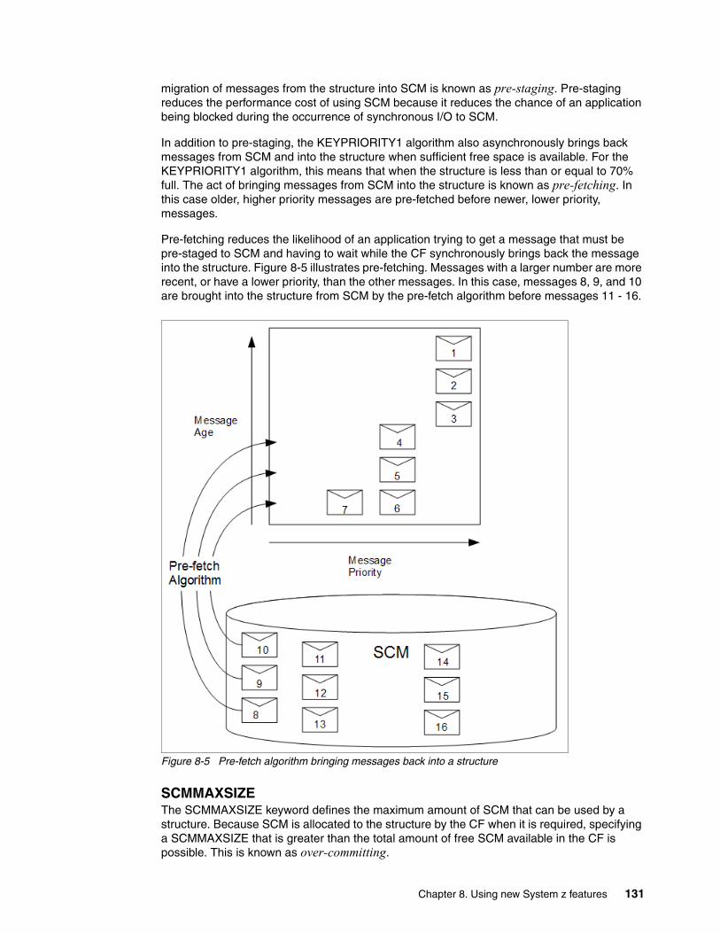
migration of messages from the structure into SCM is known as pre-staging. Pre-staging reduces the performance cost of using SCM because it reduces the chance of an application being blocked during the occurrence of synchronous I/O to SCM.
In addition to pre-staging, the KEYPRIORITY1 algorithm also asynchronously brings back messages from SCM and into the structure when sufficient free space is available. For the KEYPRIORITY1 algorithm, this means that when the structure is less than or equal to 70% full. The act of bringing messages from SCM into the structure is known as pre-fetching. In this case older, higher priority messages are pre-fetched before newer, lower priority, messages.
Pre-fetching reduces the likelihood of an application trying to get a message that must be pre-staged to SCM and having to wait while the CF synchronously brings back the message into the structure. Figure 8-5 illustrates pre-fetching. Messages with a larger number are more recent, or have a lower priority, than the other messages. In this case, messages 8, 9, and 10 are brought into the structure from SCM by the pre-fetch algorithm before messages 11 - 16.
Figure 8-5 Pre-fetch algorithm bringing messages back into a structure
SCMMAXSIZEThe SCMMAXSIZE keyword defines the maximum amount of SCM that can be used by a structure. Because SCM is allocated to the structure by the CF when it is required, specifying a SCMMAXSIZE that is greater than the total amount of free SCM available in the CF is possible. This is known as over-committing.
Chapter 8. Using new System z features 131

The CF uses various data structures to track its use of SCM. These data structures reside in the real storage that is allocated to the CF and, as a result, reduce the amount of real storage that can be used by structures. The storage used by these data structures is known as augmented space.
When a structure is configured with SCM, a small amount of real storage is allocated from the CF to the structure known as fixed augmented space. This is allocated even if the structure never actually uses any SCM. As data from the structure is stored into SCM, extra dynamic augmented space will be allocated from the spare real storage in the CF. When the data is removed from SCM, the dynamic augmented space is returned to the CF. Augmented space, either fixed or dynamic, is never taken from the real storage that is allocated to a structure.
In addition to augmented storage, when a structure is configured to use SCM, the amount of control storage used by that structure increases. This means that a list structure configured with SCM can contain fewer entries and elements than a structure of the same size without SCM being configured.
The effects of augmented space, and the increase in control storage, when SCM is configured on a structure are illustrated in Figure 8-6. Because no data was written to SCM, in Figure 8-6, no dynamic augmented space is used. If dynamic augmented space is required it will come from the CF free space. The amount of storage used was deliberately exaggerated here.
Figure 8-6 How using SCM affects storage used by CF and structure
Important: Never over-commit SCM. If you do, the applications that are relying on it will not get the behavior that they expect. For example, MQ applications using shared queues might get unexpected MQRC_STORAGE_MEDIUM_FULL reason codes.
132 IBM MQ V8 Features and Enhancements

A final important point to make is that after data is moved from the structure into SCM, and dynamic augmented space has been used, the structure cannot be altered either manually or automatically. That is, the amount of storage allocated to the structure cannot be increased or decreased, the entry-to-element ratio that is used by the structure cannot be changed, and so on. To make the structure alterable again, the structure must not have any data stored in SCM and must not be making use of dynamic augmented storage.
8.3 Use cases for SCM with MQ application structures
This section introduces the theory behind the following two use cases. To learn about the practice of these two cases (scenarios), see Chapter 13, “SCM scenarios” on page 255.
� 8.3.1, “Use case 1: Emergency storage” on page 133� 8.3.2, “Use case 2: Improved performance” on page 136
8.3.1 Use case 1: Emergency storage
SMDS and message offloading can be used in conjunction with SCM to reduce the likelihood of an MQRC_STORAGE_MEDIUM_FULL reason code being returned to an IBM MQ application during an extended outage.
Use case descriptionThis use case is illustrated in Figure 8-7 on page 134. A single shared queue, SQ1, is configured on application structure, LIST1. The putting application puts messages onto the queue; the getting application gets messages from the queue. During normal running, the queue depth is expected to be close to zero, but a business requirement indicates that the system be able to tolerate a two-hour outage of the getting application. This means that SQ1 must be able to contain two hours of messages from the putting application. Currently this process is achieved by using the default offload rules, and SMDS, so that the size of the structure is minimized, while reducing the performance cost that is associated with offloading.
Important: To understand the impact of SCM on new or existing structures, use the CFSizer tool:
http://www-947.ibm.com/systems/support/z/cfsizer/
Important: The use of SCM with CF structures is not dependent on any specific version of MQ. So, although this book provides use cases based on IBM MQ V8, any version of IBM MQ can be used. However use case one works only with MQ V7.1 and later because it requires SMDS and the offload rules.
Chapter 8. Using new System z features 133

Figure 8-7 SCM use case one, no SCM
The rate of messages being sent to SQ1 is expected to double in the short to medium term. Although the requirement that the system be able to tolerate a two-hour outage still exists, not enough real storage is available in the CF to double the size of the structure. Because the CF, which contains LIST1, resides on an zEC12, the possibility exists to associate sufficient SCM with the structure to store enough messages so that a two-hour outage can be tolerated. This configuration is shown in Figure 8-8.
Figure 8-8 SCM use case one, with SCM
134 IBM MQ V8 Features and Enhancements

Use case timelineThis use is illustrated in Figure 8-9. The figure also indicates how much dynamic augmented space is used to track data that is stored in SCM over time.
Figure 8-9 Timeline for use case one
The use case works as follows (see Figure 8-9):
� Time 0: Initially the system is in its steady state. Both the putting and getting application are running normally and the queue depth is close to, or at, zero. Meaning that the application structure is largely empty.
� Time 1: The getting application suffers an unexpected failure and stops. But the putting application continues to put messages to the queue. The structure starts to fill up.
� Time 2: After the structure reaches 70% full, the conditions of the first offload rule are met and all messages with a size greater than or equal to 32 KB are offloaded to SMDS.
� Time 3: As messages continue to be put to the shared queue, the structure continues to fill (either because of the message data being stored in the structure, or as a result of the pointers to the offloaded messages being stored in the structure). When the structure reaches 80% full, the second offload rule starts to apply and messages that are 4 KB or greater are offloaded to SMDS.
� Time 4: When the structure is past 90% full, all messages are offloaded to SMDS and only the message pointers are being placed in the structure. About this point, the pre-staging algorithm starts to run and begins moving data from the structure into SCM. Assuming all messages on the queue are the same priority, the newest messages are pre-staged. Because all messages are now being offloaded to SMDS, the data being moved into SCM is not actual message data, but instead the pointers to the messages on SMDS. As a result, the number of messages that can be stored on the combination of the structure, and the SCM and SMDS associated with the structure, is very large.
Chapter 8. Using new System z features 135

� Time 5: Eventually the getting application is available again and the outage is over. However SCM is still being used by the structure at this point. The getting application starts reading messages off the queue, getting the oldest, highest priority messages first. Because these messages were written before the structure started to fill up, they come out entirely from the real storage portion of the structure.
� Time 6: As the structure starts to empty, it goes below the threshold at which pre-staging is active, and so pre-staging stops.
� Time 7: The structure usage reduces below the point at which the offload rules take effect, so messages are no longer offloaded to SMDS unless they are more than 63 KB. At about this point, the pre-fetch algorithm starts moving data from SCM in to the structure. Because the getting application gets messages from the queue in the order expected by the SCM algorithms, messages are brought in before the getting application needs them. This means that the getting application never needs to wait for messages to be brought in synchronously from SCM.
� Time 8: As the getting application continues to move down the queue, it starts retrieving messages that were offloaded to SMDS.
� Time 9: The system is in a steady state again. No messages are stored in SCM or SMDS, and the queue depth is close to zero.
8.3.2 Use case 2: Improved performance
This use case describes using SCM to increase the number of messages that can be stored on a shared queue without incurring the performance cost of using SMDS.
Use case descriptionFor this use case, a putting and getting application communicate through a shared queue, SQ2, which is stored in application structure, LIST2. The putting application tends to run in bursts when it puts a large number of messages in a short amount of time. Then, in an extended period of time, it produces no messages at all. The getting application sequentially processes each message and performs complex processing on them. As a result, most of the time the queue depth is zero, except for when the putting application starts to run. At that point, the queue depth increases until the putting application stops and the getting application has enough time to process all the messages on the queue. This is illustrated in Figure 8-10 on page 137.
Performance: During this stage of the outage, the putting application can suffer a degree of performance degradation because of having to write to SMDS. So in this case, the use of SCM should not be a limiting factor on the putting application in terms of performance. SCM provides extra space to prevent the structure filling up.
136 IBM MQ V8 Features and Enhancements

Figure 8-10 SCM use case two, no SCM
In this use case, performance is key. The messages being sent to the queue are always less than 63 KB and so never need to be offloaded to SMDS. The application structure has been sized so that it is big enough to contain all of the messages that will be put on it by the putting application in a single “burst.” The offload rules must all be disabled so that, even when the structure starts to fill, the messages are not offloaded to SMDS. This is because the performance costs that are associated with writing messages to, and reading messages from, SMDS are deemed unacceptable.
Over time, the number of messages that the putting application send in a burst must increase by several orders of magnitude. Because the getting application must process each message sequentially, the number of messages on the queue increases to the point where the structure fills up. At this point, the putting application receives a reason code (MQRC_STORAGE_MEDIUM_FULL) when putting a message, and the put operation fails. The putting application can only briefly tolerate periods when it is unable to put messages to the queue. If the period is too long, it terminates.
This problem has five possible solutions:
1. Rewrite the putting application so that it can tolerate longer periods where it is unable to put messages to the queue.
2. Rewrite the getting application so that it can process more than one message from the queue at a time.
3. Increase the size of the application structure.
4. Add offload rules to the application structure so that messages are offloaded to SMDS as the queue starts to fill up.
5. Associate SCM with the structure.
In this case, solutions 1 and 2 are not possible because the applications are relatively complex and the skills required to significantly change them do not exist.
Solution 3 is quick to implement but not enough real storage is available on the CF.
Chapter 8. Using new System z features 137

Solution 4 might also be quick to implement but the performance impact of offloading to SMDS is considered too significant.
Solution 5, associating SCM with the structure, provides an acceptable balance of cost and performance. Solution 5 is illustrated in Figure 8-11.
Figure 8-11 Illustration of SCM use case two, solution 5
Associating SCM with a structure results in a higher use of real storage in the CF because of the augmented storage that get operations used. However, the actual amount of real storage will be less than the amount used in solution 3. Another consideration is the cost of SCM, however it is much cheaper than real storage. These factors combine to make solution 5 cheaper than solution 3.
Although solution 5 potentially might not perform as well as solution 3, the pre-fetch and pre-staging algorithms used by the CF can combine to make the differences in performance acceptable, or in some cases negligible. Certainly the performance can be much better than using SMDS to offload messages.
Use case timelineDetails of how solution 5 works can be described in the timeline shown in Figure 8-12 on page 139.
138 IBM MQ V8 Features and Enhancements

Figure 8-12 Timeline for use case two
The use case works as follows (see Figure 8-12):
� Time 0: The getting application is active and waiting for messages to be delivered to SQ2. The putting application is not active and SQ2 is empty.
� Time 1: The putting application becomes active and starts putting a large number of messages to SQ2. The getting application starts getting the messages, but the queue depth rapidly starts to increase because the getting application is slower than the putting application. As a result, the application structure starts to fill up.
� Time 2: The putting application is still active. The application structure fills up to approximately 90%. This is when the SCM pre-staging algorithm starts to move messages from the structure into SCM, freeing space in the structure. Because the getting application gets the oldest, highest priority messages from the queue first, it is always getting messages from the structure and does not need to wait for messages to be brought synchronously from SCM in to the structure.
� Time 3: The putting application is still active and putting messages to SQ2. However it never receives an MQRC_STORAGE_MEDIUM_FULL reason code because enough space exists in SCM to store all the messages that do not fit in the structure.
� Time 4: The putting application stops because it has no more messages put. The pre-staging algorithm stops because the structure falls below 90% in use. The getting application continues processing the messages in the queue.
� Time 5: As the getting application starts to free space in the structure, the pre-fetch algorithm starts to bring messages back from SCM in to the structure. Because the getting application processes messages in the order expected by the pre-fetch algorithm, the getting application never becomes blocked waiting for message data to be brought synchronously from SCM in to the structure.
� Time 6: The getting application processed all the messages on SQ2, and waits until the next message is available. The structure and SCM are empty of messages.
Chapter 8. Using new System z features 139
8.4 Using IBM zEDC with IBM MQ
IBM zEnterprise Data Compression (zEDC) is an optional feature of zEC12 and zBC12 servers. This section briefly introduces zEDC functionality and describes how it is used by IBM MQ V8.
8.4.1 Introduction to zEDC
The zEDC feature is a card that can be installed in the Peripheral Component Interconnect Express (PCIe) I/O drawers of either a zEC12 or zBC12 server. zEDC can be used to provide hardware acceleration for either the compression or decompression of data. Use of zEDC can reduce the amount of time compression or decompression takes and reduce its CPU cost.
In addition to installing the zEDC feature in either a zEC12 or zBC12 server, use of zEDC requires the following items:
� IBM z/OS V2R1 operating system� Enablement in an IFAPRDxx parmlib member
zEDC supports the DEFLATE compression format, which first compresses data using Lempel-Ziv (LZ77) compression, and then compresses it further using Huffman encoding. The DEFLATE format is standardized under RFC 1951 so, for example, data compressed using zEDC can be taken off-platform to a distributed machine and decompressed. The reverse is also possible, which is that data compressed on a distributed machine can be brought to System z and decompressed using zEDC.
At the time of writing, zEDC is used by the following items:
� SMF logger� IBM 31-bit and 64-bit SDK7 for z/OS Java Technology Edition, Version 7� DFSMS for non-VSAM compressed data sets� Applications using the zlib compression library� Applications using System z authorized zEDC interfaces
8.4.2 How IBM MQ uses zEDC
Since V6, IBM MQ channels have supported both header and message data compression in software. Compression provides benefits with channels as it reduces the amount of data that is sent over the network, potentially increasing the number of messages that can be transferred at one time. However be careful when enabling compression because not all data is that compressible, and in some cases, the cost of compressing data outweighs the benefits.
Compression can be particularly beneficial when used with channels that are configured to use either Secure Sockets Layer (SSL) or Transport Layer Security (TLS) for encryption. This is because compression of both header and message data happens before the data is encrypted. Similarly, on the other side of the channel, the decryption of the data is performed before it is decompressed.
This is illustrated in Figure 8-13 on page 141. Because encryption and decryption are computationally expensive, and the cost increases as more data is encrypted or decrypted, this can provide benefits both in terms of time and CPU usage.
140 IBM MQ V8 Features and Enhancements

Figure 8-13 Relative positions of encryption and compression in a channel
Message data compression can be specified on a per-channel basis by using the channel COMPMSG attribute. The following values are possible:
� NONE: No compression is performed. This is the default.� RLE: Run time length encoding is used.� ZLIBFAST: The zlib compression is used with a fast compression time.� ZLIBHIGH: The zlib compression is used with a high level of compression.� ANY: Any supported compression is used.
In IBM MQ V8, if both ends of a channel are configured with COMPMSG(ZLIBFAST), and the following requirements are met, the channel initiator (CHINIT) will make use of zEDC to perform either compression or decompression of message data.
� IBM MQ must be running on an LPAR that is running z/OS 2.1, with zEDC installed and enabled.
� The CHINIT user ID must be authorized to use zEDC. This is done by granting it read access to the FPZ.ACCELERATOR.COMPRESSION profile in the System Authorization Facility (SAF) FACILITY class. Sample JCL for this is provided in 14.6.2, “Authorizing the channel initiator to use zEDC” on page 299.
� The data being compressed or decompressed must meet the configured zEDC settings for the LPAR. These are described in 8.4.4, “zEDC settings” on page 143.
8.4.3 More detail of how the CHINIT address space works
Figure 8-14 on page 142 shows a detailed view of the various tasks in the CHINIT address space, with interactions indicated by arrows. This information helps in the discussion of how channel compression works in IBM MQ, and to understand the results in Chapter 14, “zEDC scenario” on page 291.
Four main sets of tasks are used by the CHINIT address space:
� Adapter tasks: These tasks performs MQI operations on the master address space.
� Dispatcher tasks: These tasks either send data over the network or receive data from it. If that data requires interaction with the master address space, for example putting a
Chapter 8. Using new System z features 141

message to a queue, the interaction is transferred to an adapter task. These tasks are also responsible for performing message compression or decompression, which might be offloaded to zEDC.
� SSL tasks: These tasks encrypt or decrypt on behalf of the dispatcher tasks.
� DNS task: This task interacts with the Domain Name System (DNS), again on behalf of the dispatcher task.
Figure 8-14 The main tasks in the CHINIT address space and their interactions
The remainder of this chapter involves the dispatcher and SSL tasks. The DNS and adapter tasks are not relevant in channel compression and therefore are not discussed further.
When sending messages over the network, the dispatcher task first splits them into segments, if needed. For normal channels, messages are split into segments, which are a maximum size of 32 KB. For channels that use SSL or TLS, the segments are a maximum size of 16 KB. Segmentation happens before compression and encryption, so it is the segments that are compressed and encrypted. The receiving side of the channel will recombine the segments after decryption and decompression.
142 IBM MQ V8 Features and Enhancements

8.4.4 zEDC settings
The three parameters that configure how zEDC works on an LPAR are as follows:
� MAXSEGMENTS� DEFMINREQSIZE� INFMINREQSIZE
These parameters can be configured in an IQPPRMxx parm lib member or changed by using the SET IQP system command.
MAXSEGMENTSApplications that use zlib to access the zEDC cards have their data compressed or decompressed in page-fixed areas of storage (segments), which are provided by the system. This parameter is used to configure the number of these segments, each of which is 16 MB. The default value for this parameter is 4, the maximum value is 64.
DEFMINREQSIZECPU overhead is associated with sending data to zEDC for compression. For small data, this overhead might be greater than the reductions in CPU that are achieved by compressing the data using zEDC. This parameter specifies the minimum data size in kilobytes (KB) that can be sent to zEDC for compression. If the data is less than this value, the data will be compressed in software. The default value is 4.
INFMINREQSIZECPU overhead is associated with sending data to zEDC for decompression. For small data, this overhead might be greater than the reductions in CPU that are achieved by decompressing the data using zEDC. This parameter specifies the minimum data size in KB that can be sent to zEDC for decompression. If the data is less than this value, the data will be decompressed in software. The default value is 16.
Considerations Because these settings are specified at the LPAR level, be careful to balance the requirements of MQ with other users of zEDC. Be particularly careful to ensure that the value of INFMINREQSIZE is suitable. This is especially true when encrypting a channel with SSL or TLS, because after compression, a 16 KB message segment will be less than the default value of INFMINREQSIZE.
Chapter 8. Using new System z features 143

Displaying settingsThe current zEDC settings can be displayed by using the D IQP system command. Sample output from this command is shown in Figure 8-15. In this example, zEDC was enabled and is using the default settings. Here, the zEDC card is not in use because zero memory segments are in use.
Figure 8-15 Example output from D IQP command
8.5 Summary
IBM MQ for z/OS has a strong track record of using new System z hardware and software features as they become available. This chapter describes how IBM MQ V8 can be used with the zEDC and SCM capabilities that are added in the zEC12 and BC12 hardware releases.
RESPONSE=SC61 IQP066I 06.29.36 DISPLAY IQP 805 zEDC Information MAXSEGMENTS: 4 (64M) Previous MAXSEGMENTS: N/A Allocated segments: 1 (16M) Used segments: 0 (0M) DEFMINREQSIZE: 4K INFMINREQSIZE: 16K Feature Enablement: Enabled
144 IBM MQ V8 Features and Enhancements

Part 3 Scenarios
This part describes several complete scenarios that demonstrate how to use some of the IBM MQ V8 features and enhancements that were described in the previous parts of this book.
This part consists of the following chapters:
� Chapter 10, “Authentication scenarios” on page 177
� Chapter 11, “CHINIT SMF scenarios” on page 199
� Chapter 12, “Advantages of a buffer pool above the bar” on page 227
� Chapter 13, “SCM scenarios” on page 255
� Chapter 14, “zEDC scenario” on page 291
Part 3
© Copyright IBM Corp. 2014. All rights reserved. 145

146 IBM MQ V8 Features and Enhancements

Chapter 9. Topic host routed publish/subscribe scenarios
This chapter describes the steps to create the base topologies, which consist of two full-repository queue managers and at least three cluster member queue managers. These queue managers represent a cluster environment to which we want to apply various distributed configurations that are detailed in subsequent sections.
This chapter contains the following topics:
� 9.1, “Environment setup” on page 148� 9.2, “A small publish/subscribe cluster: Direct routing” on page 155� 9.3, “A large publish/subscribe cluster: Topic host routing” on page 163� 9.4, “Handling proxy subscription behavior” on page 171
9
© Copyright IBM Corp. 2014. All rights reserved. 147

9.1 Environment setup
These scenarios were tested with IBM MQ V8 running on a virtual machine, on an x86 64-bit computer with 4 GB of RAM and Windows 7.
For installation instructions, see the “Installing a WebSphere MQ server” topic in the IBM MQ V8 in the “Installing” section in the IBM Knowledge Center:
http://www.ibm.com/support/knowledgecenter/SSFKSJ_8.0.0/com.ibm.mq.ins.doc/q008590_.htm
We first consider a point-to-point configuration, which sends messages from one queue manager that is directly connected to another. We then expand this simple example to work with a distributed network (simulated by creating all queue managers on the same local system) and building an architecture that can be extended by adding more queue managers to this configuration.
9.1.1 Creating and starting the cluster
Create the basic environment by completing the following steps:
1. Validate your MQ V8 installation by opening a command prompt and entering the dspmqver command.
Example 9-1 shows the output of the command, with details of your installation. You see that the information differs from information in previous versions.
Example 9-1 Output of dspmqver command
Name: WebSphere MQVersion: 8.0.0.0Level: p000-L140429.1BuildType: IKAP - (Production)Platform: WebSphere MQ for Windows (x64 platform)Mode: 64-bitO/S: Windows 7 Enterprise x64 Edition, Build 7600InstName: Installation1InstDesc: Installation for Pub/Sub ScenarioPrimary: YesInstPath: C:\Program Files\IBM\WebSphere MQDataPath: C:\ProgramData\IBM\MQMaxCmdLevel: 800LicenseType: Production
For further information, see the “dspmqver” topic in the IBM MQ V8 Migrating and upgrading section in the IBM Knowledge Center:
http://www.ibm.com/support/knowledgecenter/SSFKSJ_8.0.0/com.ibm.mq.mig.doc/q001170_.htm
2. Create and start full repository queue managers in a cluster.
An easier approach might be to write scripts to create queue managers and clusters because some of the commands are long and are often repeated. This scenario therefore uses a batch file to create clusters, as shown in the following steps, which describe the batch file listed in Example 9-2 on page 149:
a. Display the options from the .bat file execution:
• First queue manager name• First queue manager port number
148 IBM MQ V8 Features and Enhancements

• Second queue manager name• Second queue manager port number• Cluster name
b. Create and start the first queue manager:
i. Create the first queue manager with the dead letter queue option.ii. Start the queue manager.
c. Repeat step b for the second queue manager.
d. Create a .txt file that contains MQSC commands to be run on the first queue manager:
i. Set the publish/subscribe mode as PSMODE(ENABLED).
You must be sure that the publish/subscribe mode parameter is set correctly, which is why this example script uses the ALTER QMGR PSMODE command to explicitly set the mode. However, for IBM MQ V8 queue managers, the mode is set to ENABLED by default. Set the queue manager as a full repository for the cluster.
ii. Define a listener.iii. Start the listener.iv. Define a cluster-receiver channel to itself.v. Define a cluster-sender channel to the other queue manager.vi. End the MQSC session.
e. Repeat step d for the second queue manager.
f. Launch the MQSC interface against each queue manager, redirecting the corresponding file to each one.
Example 9-2 A batch-file script that creates full repositories by running MQSC commands
@echo offREM -- Step a) Display options.Echo 1st QM FR name: %1Echo 1st QM FR port: %2Echo 2nd QM FR name: %3Echo 2nd QM FR port: %4Echo cluster name: %5
REM -- Step b) Create and start the first queue manager.crtmqm -u SYSTEM.DEAD.LETTER.QUEUE %1strmqm %1
REM -- Step c) Create and start the second queue manager.crtmqm -u SYSTEM.DEAD.LETTER.QUEUE %3strmqm %3
REM -- Step d) Create a .txt file with MQSC commands for first QM.Echo ALTER QMGR PSMODE (ENABLED) >> %1.txtEcho ALTER QMGR REPOS (%5) >> %1.txtEcho DEFINE LISTENER(LISTENER.TCP) TRPTYPE(TCP) PORT(%2) CONTROL(QMGR) >> %1.txtEcho START LISTENER(LISTENER.TCP) >> %1.txtEcho DEFINE CHANNEL (TO.%1.%5) CHLTYPE (CLUSRCVR) TRPTYPE (TCP) CONNAME ('localhost(%2)') CLUSTER (%5) >> %1.txtEcho DEFINE CHANNEL (TO.%3.%5) CHLTYPE (CLUSSDR) TRPTYPE (TCP) CONNAME ('localhost(%4)') CLUSTER (%5) >> %1.txt
REM -- Step e) Create a .txt file with MQSC commands for second QM.Echo ALTER QMGR PSMODE (ENABLED) >> %3.txtEcho ALTER QMGR REPOS (%5) >> %3.txtEcho DEFINE LISTENER(LISTENER.TCP) TRPTYPE(TCP) PORT(%4) CONTROL(QMGR) >> %3.txt
Chapter 9. Topic host routed publish/subscribe scenarios 149

Echo START LISTENER(LISTENER.TCP) >> %3.txtEcho DEFINE CHANNEL (TO.%3.%5) CHLTYPE (CLUSRCVR) TRPTYPE (TCP) CONNAME ('localhost(%4)') CLUSTER (%5) >> %3.txtEcho DEFINE CHANNEL (TO.%1.%5) CHLTYPE (CLUSSDR) TRPTYPE (TCP) CONNAME ('localhost(%2)') CLUSTER (%5) >> %3.txt
REM -- Step f) Launch the MQSC interface against each queue manager.runmqsc %1 < %1.txtrunmqsc %3 < %3.txt
In this example, the batch file is named addFR.bat and is saved in the following previously created working directory:
C:\Users\Administrator\pubsub\cluster
The following names were also used:
– The name of queue managers is defined as PSXX, where XX begins at 01 and increases by 1 for each queue manager added. In this example, PS01 is for the first queue manager and PS02 is for the second queue manager.
– The listener number is defined as 14XX, where XX begins at port 14 and increases by 1 for each successive queue manager. For this example, the listener is 1414 for the first queue manager and 1415 for the second.
– The cluster name is defined as CLUS1.
Running this batch file from the command prompt produces two full repositories and gives the typical output shown in Example 9-3.
Example 9-3 Results of addFR.bat script execution.
C:\Users\Administrator\pubsub\cluster>addFR.bat PS01 1414 PS02 1415 CLUS11st QM FR name: PS011st QM FR port: 14142nd QM FR name: PS022nd QM FR port: 1415cluster name: CLUS1WebSphere MQ queue manager created.Directory 'C:\ProgramData\IBM\MQ\qmgrs\PS01' created.The queue manager is associated with installation 'Installation1'.Creating or replacing default objects for queue manager 'PS01'.Default objects statistics : 82 created. 0 replaced. 0 failed.Completing setup.Setup completed.WebSphere MQ queue manager 'PS01' starting.The queue manager is associated with installation 'Installation1'.5 log records accessed on queue manager 'PS01' during the log replay phase.Log replay for queue manager 'PS01' complete.Transaction manager state recovered for queue manager 'PS01'.WebSphere MQ queue manager 'PS01' started using V8.0.0.0.WebSphere MQ queue manager created.Directory 'C:\ProgramData\IBM\MQ\qmgrs\PS02' created.The queue manager is associated with installation 'Installation1'.Creating or replacing default objects for queue manager 'PS02'.Default objects statistics : 82 created. 0 replaced. 0 failed.Completing setup.Setup completed.WebSphere MQ queue manager 'PS02' starting.The queue manager is associated with installation 'Installation1'.5 log records accessed on queue manager 'PS02' during the log replay phase.Log replay for queue manager 'PS02' complete.Transaction manager state recovered for queue manager 'PS02'.
150 IBM MQ V8 Features and Enhancements

WebSphere MQ queue manager 'PS02' started using V8.0.0.0.5724-H72 (C) Copyright IBM Corp. 1994, 2014.Starting MQSC for queue manager PS01.
1 : ALTER QMGR PSMODE (ENABLED)AMQ8005: WebSphere MQ queue manager changed. 2 : ALTER QMGR REPOS (CLUS1)AMQ8005: WebSphere MQ queue manager changed. 3 : DEFINE LISTENER(LISTENER.TCP) TRPTYPE(TCP) PORT(1414) CONTROL(QMGR)AMQ8626: WebSphere MQ listener created. 4 : START LISTENER(LISTENER.TCP)AMQ8021: Request to start WebSphere MQ listener accepted. 5 : DEFINE CHANNEL (TO.PS01.CLUS1) CHLTYPE (CLUSRCVR) TRPTYPE (TCP) CONNAME ('localhost(1414)') CLUSTER (CLUS1)AMQ8014: WebSphere MQ channel created. 6 : DEFINE CHANNEL (TO.PS02.CLUS1) CHLTYPE (CLUSSDR) TRPTYPE (TCP) CONNAME ('localhost(1415)') CLUSTER (CLUS1)AMQ8014: WebSphere MQ channel created.6 MQSC commands read.No commands have a syntax error.All valid MQSC commands were processed.5724-H72 (C) Copyright IBM Corp. 1994, 2014.Starting MQSC for queue manager PS02.
1 : ALTER QMGR PSMODE (ENABLED)AMQ8005: WebSphere MQ queue manager changed. 2 : ALTER QMGR REPOS (CLUS1)AMQ8005: WebSphere MQ queue manager changed. 3 : DEFINE LISTENER(LISTENER.TCP) TRPTYPE(TCP) PORT(1415) CONTROL(QMGR)AMQ8626: WebSphere MQ listener created. 4 : START LISTENER(LISTENER.TCP)AMQ8021: Request to start WebSphere MQ listener accepted. 5 : DEFINE CHANNEL (TO.PS02.CLUS1) CHLTYPE (CLUSRCVR) TRPTYPE (TCP) CONNAME ('localhost(1415)') CLUSTER (CLUS1)AMQ8014: WebSphere MQ channel created. 6 : DEFINE CHANNEL (TO.PS01.CLUS1) CHLTYPE (CLUSSDR) TRPTYPE (TCP) CONNAME ('localhost(1414)') CLUSTER (CLUS1)AMQ8014: WebSphere MQ channel created.6 MQSC commands read.No commands have a syntax error.All valid MQSC commands were processed
3. Create and start partial repository queue managers in the cluster.
To create each partial repository queue manager, an batch file is used again. The following steps describe the batch file shown in Example 9-4 on page 152:
a. Display the options from .bat file execution.
• Full repository queue manager name• Full repository queue manager port number• New partial repository queue manager name• New partial repository queue manager port number• Cluster name
b. Create and start the new queue manager:
i. Create the queue manager with a dead letter queue option.ii. Start the queue manager.
Chapter 9. Topic host routed publish/subscribe scenarios 151

c. Create a .txt file that contains MQSC commands to be run on the new partial repository queue manager:
i. Set the publish/subscribe mode to ENABLED.ii. Define a listener.iii. Start the listener.iv. Define the cluster-receiver channel to itself.v. Define the cluster-sender channel to one of the full repository queue managers.
d. Launch the MQSC interface against the new partial repository queue manager, redirecting the corresponding file itself.
Example 9-4 A batch-file script that creates partial repositories by running MQSC commands.
@echo offREM -- Step a) Display options.Echo QM FR name: %1Echo QM FR port: %2Echo QM PR name: %3Echo QM PR port: %4Echo cluster name: %5
REM -- Step b) Create and start the queue manager.crtmqm -u SYSTEM.DEAD.LETTER.QUEUE %3strmqm %3
REM -- Step c) Create a .txt file with MQSC commands.Echo ALTER QMGR PSMODE (ENABLED) >> %3.txtEcho DEFINE LISTENER(LISTENER.TCP) TRPTYPE(TCP) PORT(%4) CONTROL(QMGR) >> %3.txtEcho START LISTENER(LISTENER.TCP) >> %3.txtEcho DEFINE CHANNEL (TO.%3.%5) CHLTYPE (CLUSRCVR) TRPTYPE (TCP) CONNAME ('localhost(%4)') CLUSTER (%5) >> %3.txtEcho DEFINE CHANNEL (TO.%1.%5) CHLTYPE (CLUSSDR) TRPTYPE (TCP) CONNAME ('localhost(%2)') CLUSTER (%5) >> %3.txt
REM -- Step d) Launch the MQSC interface against the queue manager.runmqsc %3 < %3.txt
In this example, the addPR.bat batch file is saved in the following previously created working directory:
C:\Users\Administrator\pubsub\cluster
The following names were also used:
– The full repository queue manager to bind the partial repository cluster-sender channel to is named PS01, using port number 1414.
– The partial repository queue manager is named PS03.
– The listener number is defined as 1416 for the partial repository queue manager.
– The cluster name defined as CLUS1.
Running this batch file from the command prompt gives the output shown in Example 9-5.
Example 9-5 Results of addPR.bat script execution.
C:\Users\Administrator\pubsub\cluster>addPR.bat PS01 1414 PS03 1416 CLUS1QM FR name: PS01QM FR port: 1414QM PR name: PS03QM PR port: 1416cluster name: CLUS1
152 IBM MQ V8 Features and Enhancements

WebSphere MQ queue manager created.Directory 'C:\ProgramData\IBM\MQ\qmgrs\PS03' created.The queue manager is associated with installation 'Installation1'.Creating or replacing default objects for queue manager 'PS03'.Default objects statistics : 82 created. 0 replaced. 0 failed.Completing setup.Setup completed.WebSphere MQ queue manager 'PS03' starting.The queue manager is associated with installation 'Installation1'.5 log records accessed on queue manager 'PS03' during the log replay phase.Log replay for queue manager 'PS03' complete.Transaction manager state recovered for queue manager 'PS03'.WebSphere MQ queue manager 'PS03' started using V8.0.0.0.5724-H72 (C) Copyright IBM Corp. 1994, 2014.Starting MQSC for queue manager PS03.
1 : ALTER QMGR PSMODE (ENABLED)AMQ8005: WebSphere MQ queue manager changed. 2 : DEFINE LISTENER(LISTENER.TCP) TRPTYPE(TCP) PORT(1416) CONTROL(QMGR)AMQ8626: WebSphere MQ listener created. 3 : START LISTENER(LISTENER.TCP)AMQ8021: Request to start WebSphere MQ listener accepted. 4 : DEFINE CHANNEL (TO.PS03.CLUS1) CHLTYPE (CLUSRCVR) TRPTYPE (TCP) CONNAME ('localhost(1416)') CLUSTER (CLUS1)AMQ8014: WebSphere MQ channel created. 5 : DEFINE CHANNEL (TO.PS01.CLUS1) CHLTYPE (CLUSSDR) TRPTYPE (TCP) CONNAME ('localhost(1414)') CLUSTER (CLUS1)AMQ8014: WebSphere MQ channel created.5 MQSC commands read.No commands have a syntax error.All valid MQSC commands were processed.
Two more partial repositories are needed to complete this scenario. To create these, run addPR.bat twice more, changing the options accordingly:
a. Add a queue manager called PS04 with port number 1417, and join it to the cluster through the PS02 queue manager with port number 1415. Run addPR.bat from a command line with the following parameters:
addPR.bat PS02 1415 PS04 1417 CLUS1
b. Add a queue manager called PS05 with port number 1418, and join it to the cluster through the PS01 queue manager with port number 1414. Run addPR.bat again, with the following parameters:
addPR.bat PS01 1414 PS05 1418 CLUS1
You have now created the cluster for this scenario.
4. You can issue a command to display your CLUS1 cluster. Start an MQSC command line for PS01 or PS02 and type the following command, which will show the results of the configuration (Example 9-6 on page 154):
DISPLAY CLUSQMGR(*) QMTYPE VERSION
Chapter 9. Topic host routed publish/subscribe scenarios 153

Example 9-6 Results of display cluster MQSC command
C:\Users\Administrator\pubsub\cluster>runmqsc -e PS015724-H72 (C) Copyright IBM Corp. 1994, 2014.Starting MQSC for queue manager PS01.
DISPLAY CLUSQMGR(*) QMTYPE VERSIONAMQ8441: Display Cluster Queue Manager details. CLUSQMGR(PS01) CHANNEL(TO.PS01.CLUS1) CLUSTER(CLUS1) QMTYPE(REPOS) VERSION(08000000)AMQ8441: Display Cluster Queue Manager details. CLUSQMGR(PS02) CHANNEL(TO.PS02.CLUS1) CLUSTER(CLUS1) QMTYPE(REPOS) VERSION(08000000)AMQ8441: Display Cluster Queue Manager details. CLUSQMGR(PS03) CHANNEL(TO.PS03.CLUS1) CLUSTER(CLUS1) QMTYPE(NORMAL) VERSION(08000000)AMQ8441: Display Cluster Queue Manager details. CLUSQMGR(PS04) CHANNEL(TO.PS04.CLUS1) CLUSTER(CLUS1) QMTYPE(NORMAL) VERSION(08000000)AMQ8441: Display Cluster Queue Manager details. CLUSQMGR(PS05) CHANNEL(TO.PS05.CLUS1) CLUSTER(CLUS1) QMTYPE(NORMAL) VERSION(08000000)ENDOne MQSC command read.No commands have a syntax error.All valid MQSC commands were processed.
If you include the RPM package when you install MQ V8, you can also view the CLUS1 cluster graphically by using MQ Explorer, which has enhanced features in V8.
Use a command prompt to start the MQ Explorer interface by entering the strmqcfg command.
Go to the navigation tab and expand the queue manager clusters section for the cluster named CLUS1 to view the full repositories and the partial repositories. Click the PS01 queue manager and see the tabs in the Content view. Click the Cluster-sender Channels tab and scroll to the right until you see the Version column as shown in Figure 9-1 on page 155. This column, added in IBM MQ V8, lists the version of MQ with which the cluster queue manager is associated.
Note: In MQ V8 the attribute VERSION has been added so that you can see when V8 queue managers coexists with others from previous versions. In order to use topic host configuration in a cluster the full repositories and partial repositories that participate in publish/subscribe messaging communication must run in V8.
154 IBM MQ V8 Features and Enhancements

Figure 9-1 Display the version associated to the cluster queue manager
9.2 A small publish/subscribe cluster: Direct routing
Now the base cluster environment is ready to start configuring on a publish/subscribe network. The clustered topics are easy to configure; having a small cluster is suitable to implement a quick and easy direct routed topology. The steps are explained in the following sections.
9.2.1 Defining the cluster topic
When a topic object is created, it uses the values of attributes that are supplied and inherits those that are not defined from the nearest parent object in the topic tree. Ultimately it inherits default values from SYSTEM.BASE.TOPIC, the root topic.
After you set up a basic cluster, as described 9.1, “Environment setup” on page 148, configure the topic parameters to give the behavior you want, through defined administrative topic objects in the queue managers.
The following settings must be defined:
� Topic object name� Topic string
In this part of the scenario, the selected values are shown by using the following procedure:
1. Launch MQSC command interface by typing the following command:
runmqsc -e PS02
2. Create the cluster topic object TENNIS.TOPIC by typing the following command:
DEFINE TOPIC(TENNIS.TOPIC) TOPICSTR('/News/Sports/Tennis') CLUSTER(CLUS1)
Chapter 9. Topic host routed publish/subscribe scenarios 155

3. Verify the topic definition by displaying the topic status by typing the following command:
DISPLAY TCLUSTER(TENNIS.TOPIC) TOPICSTR CLUSTER CLROUTE CLSTATE
4. Verify the topic tree definition that was created by typing the following command:
DISPLAY TPSTATUS('/#') TYPE(TOPIC) CLUSTER CLROUTE SUBCOUNT ADMIN
5. Finish the MQSC interface by typing the END command:
6. Repeat step 1 and steps 3 - 5 on each queue manager to verify the status of all the members.The results are similar to Example 9-7.
Example 9-7 Definition and validation commands to create direct routing topic object in cluster
C:\Users\Administrator\pubsub\cluster>runmqsc -e PS025724-H72 (C) Copyright IBM Corp. 1994, 2014.Starting MQSC for queue manager PS02.
DEFINE TOPIC(TENNIS.TOPIC) TOPICSTR('/News/Sports/Tennis') CLUSTER(CLUS1)AMQ8690: WebSphere MQ topic created.DISPLAY TCLUSTER(TENNIS.TOPIC) TOPICSTR CLUSTER CLROUTE CLSTATEAMQ8633: Display topic details. TOPIC(TENNIS.TOPIC) TYPE(CLUSTER) TOPICSTR(/News/Sports/Tennis) CLUSTER(CLUS1) CLROUTE(DIRECT) CLSTATE(ACTIVE)DISPLAY TPSTATUS('/#') TYPE(TOPIC) CLUSTER CLROUTE SUBCOUNT ADMINAMQ8754: Display topic status details. TOPICSTR() ADMIN(SYSTEM.BASE.TOPIC) CLUSTER( ) CLROUTE(NONE) SUBCOUNT(0)AMQ8754: Display topic status details. TOPICSTR(/News) ADMIN( ) CLUSTER( ) CLROUTE(NONE) SUBCOUNT(0)AMQ8754: Display topic status details. TOPICSTR(/News/Sports/Tennis) ADMIN(TENNIS.TOPIC) CLUSTER(CLUS1) CLROUTE(DIRECT) SUBCOUNT(0)AMQ8754: Display topic status details. TOPICSTR(/News/Sports) ADMIN( ) CLUSTER( ) CLROUTE(NONE) SUBCOUNT(0)END3 MQSC commands read.No commands have a syntax error.All valid MQSC commands were processed.
When these commands are completed, analyze the information that is obtained from the publish/subscribe engine.
In this example, the status of the topic in the cluster is obtained by using the MQSC command DISPLAY TCLUSTER; all topic nodes are listed by using DISPLAY TPSTATUS, and the number sign (#) as a wildcard. This shows the topic nodes from the complete tree as follows:
� Empty string� /News � /News/Sports� /News/Sports/Tennis
156 IBM MQ V8 Features and Enhancements

Several differences between the topic object parameters that are shown in this output are as follows:
� TOPICSTR is the topic string for each tree node.
� Most CLROUTE parameters are set to NONE; only for the TENNIS.TOPIC, which was previously defined, is it set to DIRECT.
� The ADMIN parameter holds the name of the administrative topic object.
� The value of CLUSTER is the name of the cluster previously created CLUS1 and appears only in the clustered topic.
� The SUBCOUNT parameter has the number of subscriptions currently aware of each respective topic node.
This is the topic knowledge that was spread to all cluster members. The publish/subscribe engine uses this information so it can match its publications to subscriptions in the same queue manager using the topic tree or in a remote queue manager connected within the network. This means that as the topic objects of the topic tree are shared through different configurations, all the queue managers can work together.
Testing the publish/subscribe clusterTo attach a sample publish/subscribe application and start to send messages through the hierarchy, you can use the amqssub and amqsput commands.
To publish a topic on one queue manager and subscribe to the topic with the other queue managers, use the following steps:
1. Open three command line windows.
2. Set up a publisher on the first command line by entering the following command:
amqspub /News/Sports/Tennis PS01
3. Concurrently, set up two subscribers on separate command lines, by entering the following commands:
amqssub /News/Sports/Tennis PS03amqssub /News/Sports/Tennis PS04
Be aware that these subscriptions have a timeout of 30 seconds and then automatically are disconnected.
4. On the first command line, enter a message. The message is displayed in both the subscribing command lines.
The result is shown in Figure 9-2 on page 158. The publish and subscribe commands are indicated.
Chapter 9. Topic host routed publish/subscribe scenarios 157
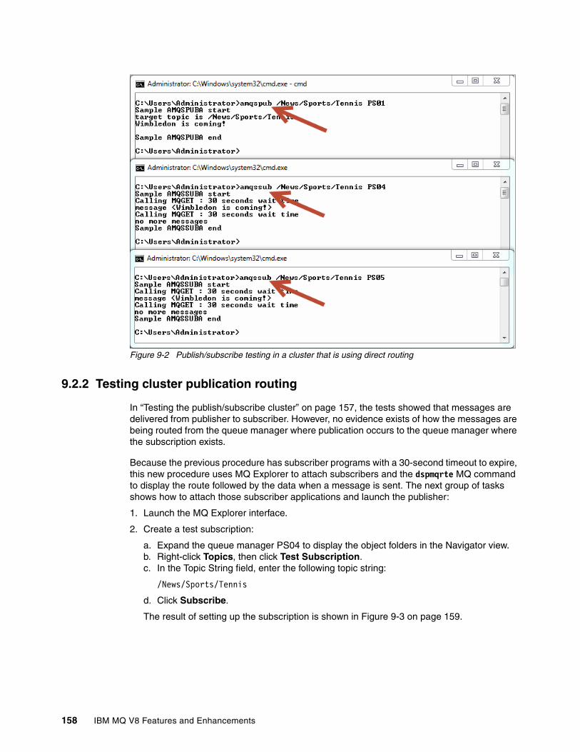
Figure 9-2 Publish/subscribe testing in a cluster that is using direct routing
9.2.2 Testing cluster publication routing
In “Testing the publish/subscribe cluster” on page 157, the tests showed that messages are delivered from publisher to subscriber. However, no evidence exists of how the messages are being routed from the queue manager where publication occurs to the queue manager where the subscription exists.
Because the previous procedure has subscriber programs with a 30-second timeout to expire, this new procedure uses MQ Explorer to attach subscribers and the dspmqrte MQ command to display the route followed by the data when a message is sent. The next group of tasks shows how to attach those subscriber applications and launch the publisher:
1. Launch the MQ Explorer interface.
2. Create a test subscription:
a. Expand the queue manager PS04 to display the object folders in the Navigator view.b. Right-click Topics, then click Test Subscription.c. In the Topic String field, enter the following topic string:
/News/Sports/Tennis
d. Click Subscribe.
The result of setting up the subscription is shown in Figure 9-3 on page 159.
158 IBM MQ V8 Features and Enhancements

Figure 9-3 Subscription window from MQ Explorer
3. Publish a message and view its route:
a. Open a command-line window.
b. Enter the display route command by using the following command:
dspmqrte -ts /News/Sports/Tennis -ac -d yes -v outline activity -w 3 -m PS01
The display message route command shows what happens when the message is published to the PS01 queue manager, including a summary of the routing details, as shown in Example 9-8.
Example 9-8 Output from the display route command
C:\Users\Administrator>dspmqrte -ts /News/Sports/Tennis -ac -d yes -v outline activity -w 3 -m PS01AMQ8653: DSPMQRTE command started with options '-ts /News/Sports/Tennis -ac -d yes -v outline activity -w 3 -m PS01'.AMQ8694: DSPMQRTE command successfully put a message to topic string '/News/Sports/Tennis', queue manager 'PS01'.AMQ8657: DSPMQRTE command used CorrelId 0x414D512050533031202020202020202069F4A15320007704.AMQ8674: DSPMQRTE command is now waiting for information to display.
--------------------------------------------------------------------------------
Activity: ApplName: 'PS01' ApplType: QMgrPublish ActivityDesc: 'Message publication'
Chapter 9. Topic host routed publish/subscribe scenarios 159

Operation: OperationType: Put QMgrName: 'PS01' TopicString: '/News/Sports/Tennis'
Operation: OperationType: Publish SubId: X'414D512050533031202020202020202069F4A15320000E41' SubLevel: 1 QMgrName: 'PS01'
--------------------------------------------------------------------------------
Activity: ApplName: 'Sphere MQ\bin64\amqrmppa.exe' ApplType: WindowsNT ActivityDesc: 'Sending Message Channel Agent'
Operation: OperationType: Get QMgrName: 'PS01' QName: 'SYSTEM.CLUSTER.TRANSMIT.QUEUE' ResolvedQName: 'SYSTEM.CLUSTER.TRANSMIT.QUEUE'
Operation: OperationType: Send QMgrName: 'PS01' RemoteQMgrName: 'PS04' ChannelName: 'TO.PS04.CLUS1' ChannelType: ClusSdr XmitQName: 'SYSTEM.CLUSTER.TRANSMIT.QUEUE'
--------------------------------------------------------------------------------
Activity: ApplName: 'Sphere MQ\bin64\amqrmppa.exe' ApplType: WindowsNT ActivityDesc: 'Receiving Message Channel Agent'
Operation: OperationType: Receive QMgrName: 'PS04' RemoteQMgrName: 'PS01' ChannelName: 'TO.PS04.CLUS1' ChannelType: ClusRcvr
Operation: OperationType: Put QMgrName: 'PS04' QName: 'SYSTEM.INTER.QMGR.PUBS' ResolvedQName: 'SYSTEM.INTER.QMGR.PUBS'
--------------------------------------------------------------------------------
Activity: ApplName: 'PS04' ApplType: QMgrPublish ActivityDesc: 'Message publication'
160 IBM MQ V8 Features and Enhancements

Operation: OperationType: Put QMgrName: 'PS04' TopicString: '/News/Sports/Tennis'
Operation: OperationType: Publish SubId: X'414D512050533034202020202020202074F4A15320005804' SubLevel: 1 QMgrName: 'PS04'
--------------------------------------------------------------------------------
AMQ8652: DSPMQRTE command has finished.
The output shows four Activity sections. The second activity shows, for example, indicates 'Sending Message Channel Agent' and shows the final destination as the remote queue manager PS04 (the queue manager where the subscription was created from MQ Explorer). In the sequence of events, the message is obtained from the transmit queue and moved through the cluster sender channel directly to the subscriber destination.
If the output (Example 9-8 on page 159) is repeated, but the name of the queue manager to which the display route application command connects is changed to PS02 and PS03, the same result of going directly to PS04 is produced.
This shows that messages are sent directly to the subscriber and the publish/subscribe engine uses the proxy subscription. Because the route command has the delivery option set to YES, an activity result shows to publish the message at the subscriber’s destination.
For further details about configuration using MQ Explorer, see the “Configuring publish/subscribe for Version 7.0 and later queue managers” topic in the MQ V8 Explorer section of IBM Knowledge Center:
http://www.ibm.com/support/knowledgecenter/SSFKSJ_8.0.0/com.ibm.mq.explorer.doc/e_pubsub_v7.htm
For more information about the dspmqrte command used in this example, see the following web page:
http://www.ibm.com/support/knowledgecenter/SSFKSJ_8.0.0/com.ibm.mq.ref.adm.doc/q083240_.htm
4. Validate proxy subscriptions in the cluster. After a subscription is created on a queue manager in the cluster, proxy subscriptions for that topic string are created.
Use the following steps:
a. Follow the procedure step 2 on page 158 to create a new subscription at the PS05 queue manager.
b. Open the command-line interface.
c. Start the MQSC command interface against queue manager PS01 by entering the following command:
runmqsc -e PS01
d. Display the proxy subscriptions for that queue manager by entering the following command:
DISPLAY SUB(*) SUBTYPE(PROXY)
Chapter 9. Topic host routed publish/subscribe scenarios 161

e. End the MQSC interface by entering the END command:
f. Repeat steps c on page 161 through e against PS02, PS03, PS04 and PS05.
After you enter the MQSC command to PS04 and PS05, the output shows only one proxy subscription in each queue manager. The output at PS01, PS02, and PS03 shows two proxy subscriptions are in each, corresponding to the current subscriptions to the topic cluster.
If you look at all the queue managers in the cluster by running the DISPLAY command for each, how the topology is set up becomes apparent. Example 9-9 shows the result from queue manager PS01.
Example 9-9 Display proxy subscriptions in a direct route cluster topic
C:\Users\Administrator>runmqsc -e PS015724-H72 (C) Copyright IBM Corp. 1994, 2014.Starting MQSC for queue manager PS01.
DISPLAY SUB(*) SUBTYPE(PROXY)AMQ8096: WebSphere MQ subscription inquired. SUBID(414D512050533031202020202020202069F4A15320000E5A) SUB(SYSTEM.PROXY.PS04 CLUS1 /News/Sports/Tennis) SUBTYPE(PROXY)AMQ8096: WebSphere MQ subscription inquired. SUBID(414D512050533031202020202020202069F4A15320000E5D) SUB(SYSTEM.PROXY.PS05 CLUS1 /News/Sports/Tennis) SUBTYPE(PROXY)ENDOne MQSC command read.No commands have a syntax error.All valid MQSC commands were processed.
Another possibility is to validate proxy subscriptions by using MQ Explorer:
a. Launch MQ Explorer.
b. Expand the queue manager PS05 to display the object-folders in the Navigator view.
c. Right-click Topics, then click Status.
d. Expand the topic tree to display the details of the Tennis node, starting from the [Empty] node.
The results are shown in Figure 9-4 on page 163. Note the columns shown.
162 IBM MQ V8 Features and Enhancements

Figure 9-4 Display cluster topic direct routing status from MQ Explorer
e. When you finish viewing the results, close the Topic Status window and the two Subscribe windows.
The results from this scenario show that two subscriptions are in the CLUS1 cluster. The two proxy subscriptions created on queue manager PS01 cause publication messages to be delivered directly to queue managers PS04 and PS05, where the matching subscriptions exist. The same occurs when the execution is tested at queue manager PS02.
However, if the execution is tested at any queue manager that holds the local subscription definition (that is PS04 or PS05), the dspmqrte command will result in publishing the message locally and sending only one copy from it to the network. The local publication will be delivered to the local subscription and the sent publication will be delivered through the proxy subscription.
This scenario demonstrates how direct routing by using a single topic definition can be achieved successfully in a cluster, and how publications flow between queue managers through proxy subscriptions.
Next, we examine the IBM MQ V8 feature for routing topics in a distributed publish/subscribe queue manager network by using topic hosts.
9.3 A large publish/subscribe cluster: Topic host routing
To demonstrate topic host routing in a distributed queue manager network, this scenario builds on the previous scenario and adapts the parameters previously set for direct routing. This section also provides commands to display the cluster information to show when the topic host queue managers become aware of routed topic definitions.
Chapter 9. Topic host routed publish/subscribe scenarios 163

9.3.1 Changing the configuration from direct to topic host routing
Only several steps are needed to change the configuration from the previous scenario.
1. Start the MQSC command interface by entering the following command at a command prompt:
runmqsc -e PS02
2. Remove the topic from the cluster by entering the following command:
ALTER TOPIC(TENNIS.TOPIC) CLUSTER('')
3. Add the topic to CLUS1 cluster with cluster route to topic host by entering the following command:
ALTER TOPIC(TENNIS.TOPIC) CLROUTE(TOPICHOST) CLUSTER(CLUS1)
4. Verify the topic definition displaying the topic status by entering the following command:
DISPLAY TCLUSTER(TENNIS.TOPIC) TOPICSTR CLUSTER CLROUTE CLSTATE
5. Close the MQSC interface by entering the END command:
6. Repeat steps 2, 5, and 6 for each queue manager in the cluster and verify the output. In particular, see that CLSTATE is set to ACTIVE. If the setting is anything other than ACTIVE, a problem might exist with communication of publish/subscribe information in the cluster that you must investigate.
Example 9-10 shows these steps being successfully applied to create a topic host routed cluster.
Example 9-10 Output of modifying a topic from direct to topic host routing
C:\Users\Administrator>runmqsc -e PS025724-H72 (C) Copyright IBM Corp. 1994, 2014.Starting MQSC for queue manager PS02.
ALTER TOPIC(TENNIS.TOPIC) CLUSTER('')AMQ8691: WebSphere MQ topic changed.ALTER TOPIC(TENNIS.TOPIC) CLROUTE(TOPICHOST) CLUSTER(CLUS1)AMQ8691: WebSphere MQ topic changed.DISPLAY TCLUSTER(TENNIS.TOPIC) TOPICSTR CLUSTER CLROUTE CLSTATEAMQ8633: Display topic details. TOPIC(TENNIS.TOPIC) TYPE(CLUSTER) TOPICSTR(/News/Sports/Tennis) CLUSTER(CLUS1) CLROUTE(TOPICHOST) CLSTATE(ACTIVE)END3 MQSC commands read.No commands have a syntax error.All valid MQSC commands were processed.
An important step is to remove the topic object from the cluster by clearing the CLUSTER parameter before the CLROUTE parameter is changed. If you do not remove the topic object first, a system error warns you to do so.
The changes to these parameters mean that the PS02 queue manager is now the topic host for the CLUS1 cluster. These configuration changes are achieved without the need for a managed restart.
164 IBM MQ V8 Features and Enhancements

Testing topic host routingYou can test that the configuration was changed correctly by following steps similar to those used in the previous scenario:
1. Create a test subscription.
Follow step 2 on page 158 to add a subscription on the PS04 queue manager.
2. Validate cluster status and proxy subscriptions.
Follow the procedure from step a on page 162 to validate the topic status in the PS02 queue manager.
Figure 9-5 shows a typical output.
Figure 9-5 Display one proxy subscription in topic status from MQ Explorer
3. Publish a message and see its route:
a. Open a command-line window.
b. Enter the following display route command:
dspmqrte -ts /News/Sports/Tennis -ac -d yes -v outline activity -w 3 -m PS01
The output of the display route command is shown in Example 9-11.
Example 9-11 Output of dspmqrte command for topic host routing
C:\Users\Administrator>dspmqrte -ts /News/Sports/Tennis -ac -d yes -v outline activity -w 3 -m PS01AMQ8653: DSPMQRTE command started with options '-ts /News/Sports/Tennis -ac -d yes -v outline activity -w 3 -m PS01'.AMQ8694: DSPMQRTE command successfully put a message to topic string '/News/Sports/Tennis', queue manager 'PS01'.AMQ8657: DSPMQRTE command used CorrelId 0x414D512050533031202020202020202069F4A1532000C004.AMQ8674: DSPMQRTE command is now waiting for information to display.
----------------------------------------------------------------------------
Chapter 9. Topic host routed publish/subscribe scenarios 165

Activity: ApplName: 'PS01' ApplType: QMgrPublish ActivityDesc: 'Message publication'
Operation: OperationType: Put QMgrName: 'PS01' TopicString: '/News/Sports/Tennis'
----------------------------------------------------------------------------Activity: ApplName: 'Sphere MQ\bin64\amqrmppa.exe' ApplType: WindowsNT ActivityDesc: 'Sending Message Channel Agent'
Operation: OperationType: Get QMgrName: 'PS01' QName: 'SYSTEM.CLUSTER.TRANSMIT.QUEUE' ResolvedQName: 'SYSTEM.CLUSTER.TRANSMIT.QUEUE'
Operation: OperationType: Send QMgrName: 'PS01' RemoteQMgrName: 'PS02' ChannelName: 'TO.PS02.CLUS1' ChannelType: ClusSdr XmitQName: 'SYSTEM.CLUSTER.TRANSMIT.QUEUE'
----------------------------------------------------------------------------Activity: ApplName: 'Sphere MQ\bin64\amqrmppa.exe' ApplType: WindowsNT ActivityDesc: 'Receiving Message Channel Agent'
Operation: OperationType: Receive QMgrName: 'PS02' RemoteQMgrName: 'PS01' ChannelName: 'TO.PS02.CLUS1' ChannelType: ClusRcvr
Operation: OperationType: Put QMgrName: 'PS02' QName: 'SYSTEM.INTER.QMGR.PUBS' ResolvedQName: 'SYSTEM.INTER.QMGR.PUBS'
----------------------------------------------------------------------------Activity: ApplName: 'PS02' ApplType: QMgrPublish ActivityDesc: 'Message publication'
Operation: OperationType: Put QMgrName: 'PS02' TopicString: '/News/Sports/Tennis'
Operation: OperationType: Publish SubId: X'414D51205053303220202020202020206DF4A15320000D61'
166 IBM MQ V8 Features and Enhancements

SubLevel: 1 QMgrName: 'PS02'
----------------------------------------------------------------------------Activity: ApplName: 'Sphere MQ\bin64\amqrmppa.exe' ApplType: WindowsNT ActivityDesc: 'Sending Message Channel Agent'
Operation: OperationType: Get QMgrName: 'PS02' QName: 'SYSTEM.CLUSTER.TRANSMIT.QUEUE' ResolvedQName: 'SYSTEM.CLUSTER.TRANSMIT.QUEUE'
Operation: OperationType: Send QMgrName: 'PS02' RemoteQMgrName: 'PS04' ChannelName: 'TO.PS04.CLUS1' ChannelType: ClusSdr XmitQName: 'SYSTEM.CLUSTER.TRANSMIT.QUEUE'
----------------------------------------------------------------------------Activity: ApplName: 'Sphere MQ\bin64\amqrmppa.exe' ApplType: WindowsNT ActivityDesc: 'Receiving Message Channel Agent'
Operation: OperationType: Receive QMgrName: 'PS04' RemoteQMgrName: 'PS02' ChannelName: 'TO.PS04.CLUS1' ChannelType: ClusRcvr
Operation: OperationType: Put QMgrName: 'PS04' QName: 'SYSTEM.INTER.QMGR.PUBS' ResolvedQName: 'SYSTEM.INTER.QMGR.PUBS'----------------------------------------------------------------------------Activity: ApplName: 'PS04' ApplType: QMgrPublish ActivityDesc: 'Message publication'
Operation: OperationType: Put QMgrName: 'PS04' TopicString: '/News/Sports/Tennis'
Operation: OperationType: Publish SubId: X'414D512050533034202020202020202074F4A1532000D504' SubLevel: 1 QMgrName: 'PS04'
----------------------------------------------------------------------------
AMQ8652: DSPMQRTE command has finished.
Chapter 9. Topic host routed publish/subscribe scenarios 167

Here is a summary of what can be seen in this output:
• Message publication at PS01• Send message from PS01 to PS02• Receive message from PS01 in PS02• Message publication in PS02• Send message to PS04 from PS02• Receive message from PS02 in PS04• Message publication at PS04
You can extend this scenario by adding a second subscription on another queue manager.
4. Follow the procedure in step 2 on page 158 to add a subscription to the PS05 queue manager.
5. Again, validate the cluster proxy subscriptions:
a. Click Refresh in the window that is still open from step 2 on page 165. The result is shown in Figure 9-6.
Figure 9-6 Display two proxy subscriptions in topic status from MQ Explorer
b. Close the Topic Status window and close the Subscriber windows.
You can confirm the new proxy subscriptions by entering the DISPLAY SUB command in an MQSC interface running against topic host queue manager PS02. If this command is also entered on all the other members of the cluster, the output of every running queue manager will show that no subscriptions are found. As expected, there are only the two proxy subscriptions that were created at the topic host queue manager.
The subscription objects are defined as local at the same places as with the direct routing scenario, and the cluster topic configuration was resynchronized when the CLUSTER value of the topic object was changed by the last ALTER command.
The expected behavior from the topic host configuration can be demonstrated by using the display route command, dspmqrte. The same result is obtained if the queue manager option is changed to a different member of the cluster to move the publisher location.
168 IBM MQ V8 Features and Enhancements

If the display route command is entered against queue managers PS01, PS03, PS04, and PS05, the first activity is always the message publication, and the second is the message being sent to the topic host. When the publication occurs at PS02, the put operation of the message will be forwarded to the corresponding channels related to queue managers from current proxy subscriptions.
9.3.2 Configuring workload balancing
You can define the same name in a cluster topic object with the topic host route parameter on more than one queue manager in the cluster. This enables topic host route workload balancing and increases availability in the configuration.
Use the following steps to create the new topic object, which will enable the new topic host queue manager PS03:
1. Open a command line and start the MQSC command interface by entering the following command:
runmqsc -e PS01
2. Create the cluster topic object TENNIS.TOPIC by entering the following command:
DEFINE TOPIC(TENNIS.TOPIC) TOPICSTR('/News/Sports/Tennis') CLUSTER(CLUS1) CLROUTE(TOPICHOST)
3. Verify the topic definition displaying the topic status by entering the following command:
DISPLAY TCLUSTER(TENNIS.TOPIC) TOPICSTR CLUSTER CLROUTE CLSTATE
4. Verify the two proxy subscriptions in current queue manager PS01, one pointing to PS04 and one pointing to PS05 by entering the following command:
DISPLAY SUB(*) SUBTYPE(PROXY)
5. Close the MQSC interface by entering the END command:
6. Repeat step 2 and steps 4 - 6 for each cluster member to validate that the CLSTATE parameter is set to ACTIVE.
Now both topic host queue managers, PS01 and PS02, have all the proxy subscriber information and are ready to route publications according to their availability.
9.3.3 Testing workload balancing
You can test the routing to demonstrate workload balancing with the following steps:
1. Open the MQ explorer interface.
2. Create two subscriptions in the cluster, at queue managers PS04 and PS05.
Follow the procedure in step 2 on page 158 to add a subscription to each requested queue manager.
3. Open a command-line window.
4. Enter the following display route command to publish a message from PS03:
dspmqrte -ts /News/Sports/Tennis -ac -d yes -v outline activity -w 3 -m PS03
The output is similar to output shown previously, but is too large to illustrate here. The following list summarizes activities and operations, in the order in which they occur:
a. Message publication from PS03 queue manager
i. Put message with topic string /News/Sports/Tennis
Chapter 9. Topic host routed publish/subscribe scenarios 169
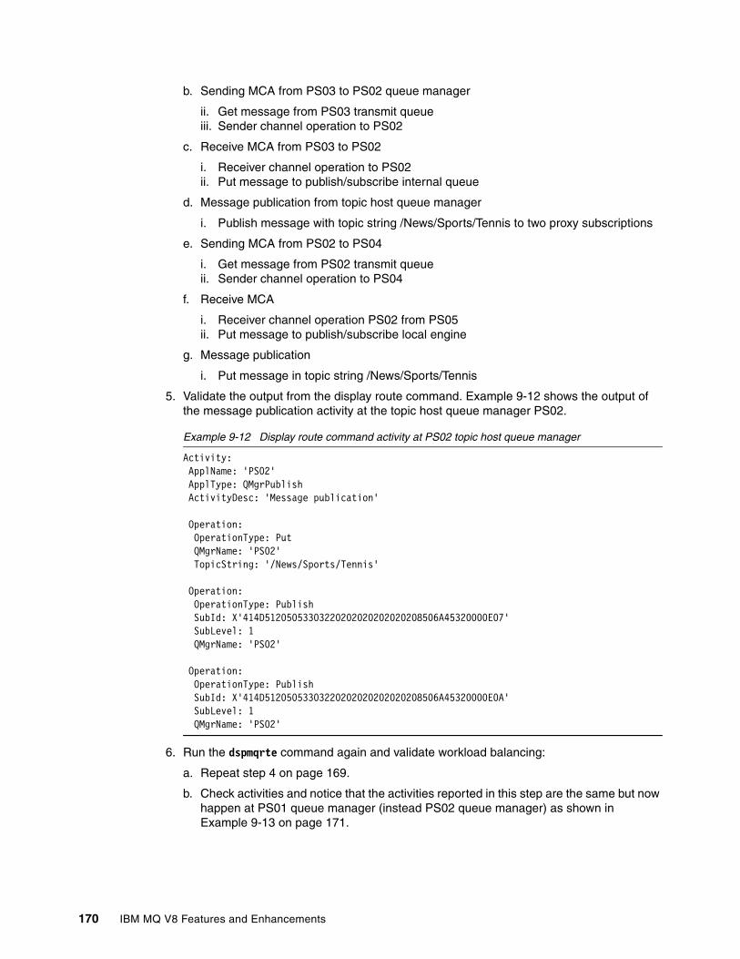
b. Sending MCA from PS03 to PS02 queue manager
ii. Get message from PS03 transmit queueiii. Sender channel operation to PS02
c. Receive MCA from PS03 to PS02
i. Receiver channel operation to PS02ii. Put message to publish/subscribe internal queue
d. Message publication from topic host queue manager
i. Publish message with topic string /News/Sports/Tennis to two proxy subscriptions
e. Sending MCA from PS02 to PS04
i. Get message from PS02 transmit queueii. Sender channel operation to PS04
f. Receive MCA
i. Receiver channel operation PS02 from PS05ii. Put message to publish/subscribe local engine
g. Message publication
i. Put message in topic string /News/Sports/Tennis
5. Validate the output from the display route command. Example 9-12 shows the output of the message publication activity at the topic host queue manager PS02.
Example 9-12 Display route command activity at PS02 topic host queue manager
Activity: ApplName: 'PS02' ApplType: QMgrPublish ActivityDesc: 'Message publication'
Operation: OperationType: Put QMgrName: 'PS02' TopicString: '/News/Sports/Tennis'
Operation: OperationType: Publish SubId: X'414D51205053303220202020202020208506A45320000E07' SubLevel: 1 QMgrName: 'PS02'
Operation: OperationType: Publish SubId: X'414D51205053303220202020202020208506A45320000E0A' SubLevel: 1 QMgrName: 'PS02'
6. Run the dspmqrte command again and validate workload balancing:
a. Repeat step 4 on page 169.
b. Check activities and notice that the activities reported in this step are the same but now happen at PS01 queue manager (instead PS02 queue manager) as shown in Example 9-13 on page 171.
170 IBM MQ V8 Features and Enhancements

Example 9-13 Display route command activity at PS01 topic host queue manager
Activity: ApplName: 'PS01' ApplType: QMgrPublish ActivityDesc: 'Message publication'
Operation: OperationType: Put QMgrName: 'PS01' TopicString: '/News/Sports/Tennis'
Operation: OperationType: Publish SubId: X'414D51205053303120202020202020208406A45320000803' SubLevel: 1 QMgrName: 'PS01'
Operation: OperationType: Publish SubId: X'414D51205053303120202020202020208406A45320000806' SubLevel: 1 QMgrName: 'PS01'
7. Close the Subscription windows for queue managers PS04 and PS05, and close the command-line window.
You typically will find that overall, there is a 50% probability that a publication will be routed through either of the two topic host queue managers, which is what we found in these tests. The first message went to PS02, then the second to PS01, as expected. However, the actual route is determined internally by the cluster workload management algorithm and is affected by many factors including the transmission of other messages, generated internally.
9.4 Handling proxy subscription behavior
In the last part of this scenario, we demonstrate that if the PROXYSUB attribute of the topic object is changed to FORCE, the behavior is quite different from before. This change affects how proxy subscriptions are created.
Starting from the same configuration as in the previous section (9.3.3, “Testing workload balancing” on page 169), follow these steps to change the value of the attribute:
1. Open command line window and start the MQSC interface against PS01 queue manager by entering the following command:
runmqsc -e PS01
2. Change the value of the PROXYSUB attribute of TENNIS.TOPIC topic object defined on the PS01 queue manager to FORCE, by entering the following command:
ALTER TOPIC(TENNIS.TOPIC) PROXYSUB(FORCE)
3. Validate proxy subscriptions created in PS01 by entering the following command:
DISPLAY SUB(*) SUBTYPE(PROXY)
Example 9-14 on page 172 shows the output of these steps.
Chapter 9. Topic host routed publish/subscribe scenarios 171
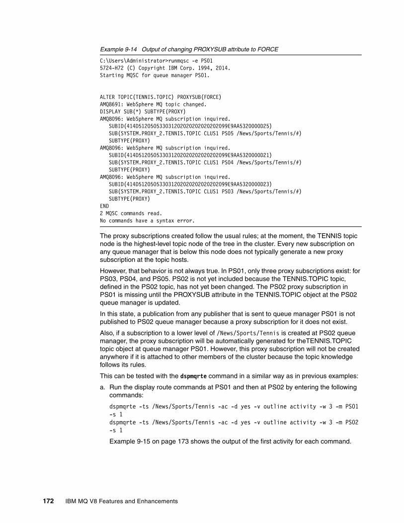
Example 9-14 Output of changing PROXYSUB attribute to FORCE
C:\Users\Administrator>runmqsc -e PS015724-H72 (C) Copyright IBM Corp. 1994, 2014.Starting MQSC for queue manager PS01.
ALTER TOPIC(TENNIS.TOPIC) PROXYSUB(FORCE)AMQ8691: WebSphere MQ topic changed.DISPLAY SUB(*) SUBTYPE(PROXY)AMQ8096: WebSphere MQ subscription inquired. SUBID(414D512050533031202020202020202099E9AA5320000D25) SUB(SYSTEM.PROXY_2.TENNIS.TOPIC CLUS1 PS05 /News/Sports/Tennis/#) SUBTYPE(PROXY)AMQ8096: WebSphere MQ subscription inquired. SUBID(414D512050533031202020202020202099E9AA5320000D21) SUB(SYSTEM.PROXY_2.TENNIS.TOPIC CLUS1 PS04 /News/Sports/Tennis/#) SUBTYPE(PROXY)AMQ8096: WebSphere MQ subscription inquired. SUBID(414D512050533031202020202020202099E9AA5320000D23) SUB(SYSTEM.PROXY_2.TENNIS.TOPIC CLUS1 PS03 /News/Sports/Tennis/#) SUBTYPE(PROXY)END2 MQSC commands read.No commands have a syntax error.
The proxy subscriptions created follow the usual rules; at the moment, the TENNIS topic node is the highest-level topic node of the tree in the cluster. Every new subscription on any queue manager that is below this node does not typically generate a new proxy subscription at the topic hosts.
However, that behavior is not always true. In PS01, only three proxy subscriptions exist: for PS03, PS04, and PS05. PS02 is not yet included because the TENNIS.TOPIC topic, defined in the PS02 topic, has not yet been changed. The PS02 proxy subscription in PS01 is missing until the PROXYSUB attribute in the TENNIS.TOPIC object at the PS02 queue manager is updated.
In this state, a publication from any publisher that is sent to queue manager PS01 is not published to PS02 queue manager because a proxy subscription for it does not exist.
Also, if a subscription to a lower level of /News/Sports/Tennis is created at PS02 queue manager, the proxy subscription will be automatically generated for theTENNIS.TOPIC topic object at queue manager PS01. However, this proxy subscription will not be created anywhere if it is attached to other members of the cluster because the topic knowledge follows its rules.
This can be tested with the dspmqrte command in a similar way as in previous examples:
a. Run the display route commands at PS01 and then at PS02 by entering the following commands:
dspmqrte -ts /News/Sports/Tennis -ac -d yes -v outline activity -w 3 -m PS01 -s 1dspmqrte -ts /News/Sports/Tennis -ac -d yes -v outline activity -w 3 -m PS02 -s 1
Example 9-15 on page 173 shows the output of the first activity for each command.
172 IBM MQ V8 Features and Enhancements

Example 9-15 Display message route commands for a forced proxy subscription
dspmqrte -ts /News/Sports/Tennis -ac -d yes -v outline activity -w 3 -m PS01 -s 1
Activity: ApplName: 'PS01' ApplType: QMgrPublish ActivityDesc: 'Message publication'
Operation: OperationType: Put QMgrName: 'PS01' TopicString: '/News/Sports/Tennis'
Operation: OperationType: Publish SubId: X'414D512050533031202020202020202099E9AA5320000D21' SubLevel: 1 QMgrName: 'PS01'
Operation: OperationType: Publish SubId: X'414D512050533031202020202020202099E9AA5320000D23' SubLevel: 1 QMgrName: 'PS01'
Operation: OperationType: Publish SubId: X'414D512050533031202020202020202099E9AA5320000D25' SubLevel: 1 QMgrName: 'PS01'-------------------------------------------------------------------------dspmqrte -ts /News/Sports/Tennis -ac -d yes -v outline activity -w 3 -m PS02 -s 1
Activity: ApplName: 'PS02' ApplType: QMgrPublish ActivityDesc: 'Message publication'
Operation: OperationType: Put QMgrName: 'PS02' TopicString: '/News/Sports/Tennis'
Operation: OperationType: Publish SubId: X'414D5120505330322020202020202020AFE9AA5320000925' SubLevel: 1 QMgrName: 'PS02'
Operation: OperationType: Publish SubId: X'414D5120505330322020202020202020AFE9AA5320000928' SubLevel: 1 QMgrName: 'PS02'
Operation: OperationType: Publish SubId: X'414D5120505330322020202020202020AFE9AA532000092A' SubLevel: 1 QMgrName: 'PS02'
Chapter 9. Topic host routed publish/subscribe scenarios 173

Operation: OperationType: Publish SubId: X'414D5120505330322020202020202020AFE9AA532000092C' SubLevel: 1 QMgrName: 'PS02'
This example shows the activities taking place as expected: three publish operations at PS01 and four at PS02.
b. Attach a subscriber with the topic string /News/Sports/Tennis/Wimbledon to queue manager PS02.
Repeat the procedure at step 2 on page 158 to add the subscription, changing the topic string from the sub-step c for the PS02 queue manager.
c. Again, validate proxy subscriptions at queue managers PS01 and PS02.
Repeat the procedure from step 1 on page 171 through step 3 on page 171 for each queue manager.
Compare the results from your output with Example 9-16 and Example 9-17 on page 175.
Example 9-16 Output from displaying PS01 proxy subscriptions when PROXYSUB attribute is inconsistent through topic definitions
C:\Users\Administrator>runmqsc -e PS015724-H72 (C) Copyright IBM Corp. 1994, 2014.Starting MQSC for queue manager PS01.
DISPLAY SUB(*) SUBTYPE(PROXY)AMQ8096: WebSphere MQ subscription inquired. SUBID(414D512050533031202020202020202099E9AA5320000D25) SUB(SYSTEM.PROXY_2.TENNIS.TOPIC CLUS1 PS05 /News/Sports/Tennis/#) SUBTYPE(PROXY)AMQ8096: WebSphere MQ subscription inquired. SUBID(414D512050533031202020202020202099E9AA5320000D21) SUB(SYSTEM.PROXY_2.TENNIS.TOPIC CLUS1 PS04 /News/Sports/Tennis/#) SUBTYPE(PROXY)AMQ8096: WebSphere MQ subscription inquired. SUBID(414D512050533031202020202020202099E9AA5320000D2D) SUB(SYSTEM.PROXY_2.TENNIS.TOPIC CLUS1 PS02 /News/Sports/Tennis/Wimbledon) SUBTYPE(PROXY)AMQ8096: WebSphere MQ subscription inquired. SUBID(414D512050533031202020202020202099E9AA5320000D23) SUB(SYSTEM.PROXY_2.TENNIS.TOPIC CLUS1 PS03 /News/Sports/Tennis/#) SUBTYPE(PROXY)ENDOne MQSC command read.No commands have a syntax error.All valid MQSC commands were processed.
174 IBM MQ V8 Features and Enhancements

Example 9-17 Output from display proxy subscriptions at PS02 demonstrating that PROXYSUB attribute settled as FORCE will not generate more proxy subscriptions
C:\Users\Administrator>runmqsc -e PS025724-H72 (C) Copyright IBM Corp. 1994, 2014.Starting MQSC for queue manager PS02.
DISPLAY SUB(*) SUBTYPE(PROXY)AMQ8096: WebSphere MQ subscription inquired. SUBID(414D5120505330322020202020202020AFE9AA532000092C) SUB(SYSTEM.PROXY_2.TENNIS.TOPIC CLUS1 PS05 /News/Sports/Tennis/#) SUBTYPE(PROXY)AMQ8096: WebSphere MQ subscription inquired. SUBID(414D5120505330322020202020202020AFE9AA5320000928) SUB(SYSTEM.PROXY_2.TENNIS.TOPIC CLUS1 PS04 /News/Sports/Tennis/#) SUBTYPE(PROXY)AMQ8096: WebSphere MQ subscription inquired. SUBID(414D5120505330322020202020202020AFE9AA5320000925) SUB(SYSTEM.PROXY_2.TENNIS.TOPIC CLUS1 PS01 /News/Sports/Tennis/#) SUBTYPE(PROXY)AMQ8096: WebSphere MQ subscription inquired. SUBID(414D5120505330322020202020202020AFE9AA532000092A) SUB(SYSTEM.PROXY_2.TENNIS.TOPIC CLUS1 PS03 /News/Sports/Tennis/#) SUBTYPE(PROXY)ENDOne MQSC command read.No commands have a syntax error.All valid MQSC commands were processed.
Example 9-16 on page 174 shows the /News/Sports/Tennis/Wimbledon topic string proxy subscription. To remove that and make the definitions consistent, follow the remaining steps in the scenario:
4. Change the value of the PROXYSUB attribute to FORCE in the TENNIS.TOPIC topic object on queue manager PS02.
a. Repeat from step 1 on page 171 to 3 on page 171 but use PS02 as the queue manager value. Example 9-18 shows the result.
Example 9-18 Output of changing PROXYSUB attribute to FORCE value in TENNIS.TOPIC topic definition at PS02 queue manager
C:\Users\Administrator>runmqsc -e PS025724-H72 (C) Copyright IBM Corp. 1994, 2014.Starting MQSC for queue manager PS02.
ALTER TOPIC(TENNIS.TOPIC) PROXYSUB(FORCE)AMQ8691: WebSphere MQ topic changed.ENDOne MQSC command read.No commands have a syntax error.All valid MQSC commands were processed.
5. Validate proxy subscriptions at PS01 and PS02.
The Wimbledon proxy subscription is now gone, and is replaced by the topic string /News/Sports/Tennis/#, which uses a wildcard. From now, every publication in the cluster at the /News/Sports/Tennis level of the topic tree or below, will be broadcast even if there are no subscribers.
Chapter 9. Topic host routed publish/subscribe scenarios 175

176 IBM MQ V8 Features and Enhancements

Chapter 10. Authentication scenarios
This chapter presents several scenarios where programs are connecting to queue managers with different authentication configurations. They show how to do the configuration, how to verify that the configuration is working as expected, and how to troubleshoot problems.
This chapter contains the following topics:
� 10.1, “System preparation and configuration” on page 178� 10.2, “Test application” on page 180� 10.3, “AIX queue manager using OS authentication” on page 183� 10.4, “z/OS queue manager using OS authentication” on page 189� 10.5, “AIX queue manager using LDAP authentication” on page 194� 10.6, “Summary” on page 198
10
© Copyright IBM Corp. 2014. All rights reserved. 177

10.1 System preparation and configuration
This section describes the setup of systems for the scenarios.
10.1.1 AIX
Four user IDs are defined on the IBM AIX® system and will be used throughout these scenarios. The user IDs and their passwords are as follows:
User ID Passwordrbosid1 pwosid1rbmqid1 pwmqid1 rbchid1 pwchid1 rbldid1 pwldid1
All of these user IDs belong to the same group, rbgrp1. The tests in the remainder of this chapter are all run from a terminal where user ID rbosid1 is logged on.
A new queue manager, QMRB, is created and started. This queue manager is defined to use user-based authorization, with the -oa user option, to help you more easily see the behavior when permissions are modified for the user IDs.
On this system, IBM MQ V8 is installed under the following location:
/unpack/mq_install/mqm.80/usr/mqm as Installation5
The system has no primary installation. More information about working with multiple installations, in particular the setmqenv command, is available in IBM WebSphere MQ V7.1 and V7.5 Features and Enhancements, SG24-8087.
Figure 10-1 shows the MQSC script used for initial definitions on this queue manager.
Figure 10-1 Initial configuration of the AIX queue manager
* Define a SVRCONN channel DEFINE CHL(TO.QMRB) CHLTYPE(SVRCONN)
* Define and start a listenerDEFINE LISTENER(QMRB) TRPTYPE(TCP) + PORT(2716) + CONTROL(QMGR)START LISTENER(QMRB)
* Override the default blocking rule for admin users for this channel* Anyone can connect through this channelSET CHLAUTH('TO.QMRB') TYPE(BLOCKUSER) USERLIST(none) + ACTION(REPLACE)
* Enable security eventsALTER QMGR AUTHOREV(ENABLED)
* Allow two of the user IDs to connect to the qmgrSET AUTHREC OBJTYPE(QMGR) PRINCIPAL('rbosid1') AUTHADD(connect)SET AUTHREC OBJTYPE(QMGR) PRINCIPAL('rbldid1') AUTHADD(connect)
178 IBM MQ V8 Features and Enhancements

10.1.2 z/OS configuration
Queue manager CSQ5 was previously created, with a listener running on port 1521. Additional configuration set up the definitions needed for this test, as shown in Figure 10-2.
Figure 10-2 Initial configuration of the z/OS queue manager
No CHLAUTH rules were enabled that affected this channel.
A user ID, TAYLOR, was defined to z/OS with the password set to PASSW0RD.
10.1.3 LDAP configuration
An LDAP server was available to demonstrate authentication. This server uses standard schemas and has had little additional configuration beyond the default provided with the product. The parent entry (ou=users,o=ibm,c=uk) was previously created.
A single entry was created for this exercise, as shown in Figure 10-3. The inetOrgPerson object class requires an sn (surname) value to be supplied. Other fields are optional in the object, but some will be used for the authentication process in MQ. Most enterprise directories are likely to have similar fields, even if they are named differently. The uid field is designated here as the field that will contain short names that can fit into 12 characters, and which will be used for authorization. The password specified here differs from the password set for the corresponding ID created on the AIX system.
Figure 10-3 User ID definition in LDIF format
DEFINE AUTHINFO(RB) AUTHTYPE(IDPWOS) + ADOPTCTX(NO)
ALTER QMGR CONNAUTH(RB)REFRESH SECURITY TYPE(CONNAUTH)
* Channel to be used for testing authenticationDEF CHL(TO.CSQ5) CHLTYPE(SVRCONN) TRPTYPE(TCP)
dn: cn=MQ User1,ou=users,o=ibm,c=ukobjectClass: inetOrgPersonsn: MQU1mail: [email protected]=SO212JNuid: rbldid1userPassword: ldappwldid1
Chapter 10. Authentication scenarios 179

10.2 Test application
The program used to exercise the authentication process is simple, only checking whether a connection can be made or not. The source code for this program is shown in Figure 10-4 on page 181 and Figure 10-5 on page 182. This program, amqsauth, takes up to three parameters on the command line: the queue manager name, a user ID, and a password. It tries to connect to the queue manager as a client, and if successful delays for 10 seconds to allow the status to be viewed from an administrative console.
Having a password on the command line is of course a bad idea, and no real application should copy this technique directly. But it is useful for these tests, showing clearly what is being used.
On z/OS, authorization does not take place for client applications until they go beyond the connection process, such as when they try to open a queue. But this test application is still useful to demonstrate the authentication operation. The connection status shows the effective user ID.
180 IBM MQ V8 Features and Enhancements

Figure 10-4 Part 1 of 2: amqsauth source code
#include <stdio.h> #include <stdlib.h> #include <string.h> #include <cmqc.h>
int main(int argc, char **argv) { /* Declare MQI structures needed */ MQCNO cno = {MQCNO_DEFAULT}; /* connection options */ MQCSP csp = {MQCSP_DEFAULT}; /* security parameters */
MQHCONN Hcon; /* connection handle */ MQLONG CompCode; /* completion code */ MQLONG Reason; /* reason code */ char *UserId = NULL; char *Password = NULL; char QMName[MQ_Q_MGR_NAME_LENGTH + 1] = {0};
if (argc < 2) { printf("Required parameter missing - queue mgr name\n"); exit(99); }
/******************************************************************/ /* Setup any authentication information supplied on command line */ /******************************************************************/ if (argc > 2) UserId = argv[2]; if (argc > 3) Password = argv[3];
if (UserId != NULL) { /****************************************************************/ /* Set the connection options to use the security structure and */ /* set version information to ensure the structure is processed.*/ /****************************************************************/ cno.SecurityParmsPtr = &csp; cno.Version = MQCNO_VERSION_5;
csp.AuthenticationType = MQCSP_AUTH_USER_ID_AND_PWD; csp.CSPUserIdPtr = UserId;
csp.CSPUserIdLength = strlen(UserId);
csp.CSPPasswordPtr = Password; if (Password != NULL) csp.CSPPasswordLength = strlen(csp.CSPPasswordPtr); }
Chapter 10. Authentication scenarios 181

Figure 10-5 Part 2 of 2: amqsauth source code
Figure 10-6 shows the simple Makefile that is used to build this program on AIX. The program is linked with libmqic, showing it is a client-enabled application. The program was compiled with 64-bit and threaded options for convenience so that it could use the same channel exit as the runmqsc program in some of these tests.
Figure 10-6 The Makefile for building amqsauth on AIX
/******************************************************************/ /* Connect to queue manager */ /******************************************************************/ if (argc > 1) strncpy(QMName, argv[1], (size_t)MQ_Q_MGR_NAME_LENGTH);
MQCONNX(QMName, &cno, &Hcon, &CompCode, &Reason);
/* report reason and stop if it failed */ if (CompCode == MQCC_FAILED) { printf("MQCONNX ended with reason code %d\n", Reason); exit( (int)Reason ); } else if (CompCode == MQCC_WARNING) { printf("MQCONNX generated a warning with reason code %d\n", Reason); printf("Continuing...\n"); } else printf("MQCONNX succeeded\n");
sleep(10); /* Delay long enough to check connection status */
MQDISC(&Hcon, &CompCode, &Reason);
return(0); }
MQDIR=/unpack/mq_install/mqm.80/usr/mqm
amqsauth: amqsauth.c xlc_r -q 64 -o $@ [email protected] -I$(MQDIR)/inc -L$(MQDIR)/lib -lmqic_r
182 IBM MQ V8 Features and Enhancements

10.3 AIX queue manager using OS authentication
This section shows the application connecting in various ways to the AIX queue manager. Although the test application and the queue manager are running on the same machine, a client connection is still being made, using localhost as the destination system. The behavior shown here is the same for all the distributed platforms.
10.3.1 No explicit authentication
The first test uses no explicit authentication, and relies on the client-asserted user ID. The top part of Figure 10-7 shows the application connecting, and the bottom part shows the connection status from a runmqsc session. The USERID value in this status shows that the operating system user ID was accepted, unchanged.
Figure 10-7 Connection with no explicit authentication
rbosid1 $ export MQSERVER="TO.QMRB/TCP/localhost(2716)"rbosid1 $ amqsauth QMRBMQCONNX succeeded
1 : DIS CONN(*) USERID APPLTAG WHERE(CHANNEL EQ 'TO.QMRB')AMQ8276: Display Connection details. CONN(53997FC420005203) EXTCONN(414D5143514D52422020202020202020) TYPE(CONN) APPLTAG(amqsauth) CHANNEL(TO.QMRB) USERID(rbosid1)
Chapter 10. Authentication scenarios 183

10.3.2 Authentication without administrative overrides
This batch of tests shows that authentication of the program-provided user ID is occurring. Figure 10-8 demonstrates that a bad password is rejected, with the corresponding event message that contains both user IDs.
Figure 10-8 Failed authentication
Figure 10-9 shows that when the correct password is given, the connection succeeds but is still being associated with the user ID that is running the application rather than the authenticated user ID.
Figure 10-9 Authentication without adopting context
rbosid1 $ export MQSERVER="TO.QMRB/TCP/localhost(2716)"rbosid1 $ amqsauth QMRB rbmqid1 badpwMQCONNX ended with reason code 2035
16/06/14 13:02:32 - Process(51380376.47) User(mqm) Program(amqzlaa0) Host(rockall.hursley.ibm.com) Installation(Installation5) VRMF(8.0.0.0) QMgr(QMRB)
AMQ5534: User ID 'rbmqid1' authentication failed
EXPLANATION:The user ID and password supplied by 'amqsauth' could not be authenticated.ACTION:Ensure that the correct user ID and password are provided by the application.Ensure that the authentication repository is correctly configured. Look atprevious error messages for any additional information.
[2014/06/16 13:02:33 BST] Not Authorized [2035] Event Type : Queue Manager Queue Manager Name : QMRB Reason Qualifier : Csp Not Authorized [29] User Identifier : rbosid1 Csp User Identifier : rbmqid1 Appl Type : Unix Appl Name : amqsauth
rbosid1 $ export MQSERVER="TO.QMRB/TCP/localhost(2716)"rbosid1 $ amqsauth QMRB rbmqid1 pwmqid1MQCONNX succeeded
1 : DIS CONN(*) USERID APPLTAG WHERE(CHANNEL EQ 'TO.QMRB')AMQ8276: Display Connection details. CONN(53997FC420005803) EXTCONN(414D5143514D52422020202020202020) TYPE(CONN) APPLTAG(amqsauth) CHANNEL(TO.QMRB) USERID(rbosid1)
184 IBM MQ V8 Features and Enhancements

Figure 10-10 shows the next step for authentication, where the user ID given by the application is adopted by the connection. The authentication is successful, but because this user ID was not granted connect authorization, the connection fails and the corresponding event message and error log message show the reason for the failure.
Figure 10-10 Authentication with adopted context
alter authinfo(system.default.authinfo.idpwos) authtype(idpwos) adoptctx(yes) 1 : alter authinfo(system.default.authinfo.idpwos) authtype(idpwos) adoptctx(yes)AMQ8567: WebSphere MQ authentication information changed.refresh security 2 : refresh securityAMQ8560: WebSphere MQ security cache refreshed.
rbosid1 $ export MQSERVER="TO.QMRB/TCP/localhost(2716)"rbosid1 $ amqsauth QMRB rbmqid1 pwmqid1MQCONNX ended with reason code 2035
16/06/14 13:03:34 - Process(51380376.48) User(mqm) Program(amqzlaa0) Host(rockall.hursley.ibm.com) Installation(Installation5) VRMF(8.0.0.0) QMgr(QMRB)
AMQ8077: Entity 'rbmqid1 ' has insufficient authority to access object'QMRB'.
EXPLANATION:The specified entity is not authorized to access the required object. Thefollowing requested permissions are unauthorized: connectACTION:Ensure that the correct level of authority has been set for this entity againstthe required object, or ensure that the entity is a member of a privilegedgroup.
[2014/06/16 13:03:34 BST] Not Authorized [2035] Event Type : Queue Manager Queue Manager Name : QMRB Reason Qualifier : Conn Not Authorized [1] User Identifier : rbmqid1 Csp User Identifier : rbmqid1 Appl Type : Unix Appl Name : amqsauth
Chapter 10. Authentication scenarios 185

Finally, in this batch as Figure 10-11 shows, the authorization for the adopted user ID is corrected and the application is connected with the authenticated identity.
Figure 10-11 Authentication with adopted context and authorization
10.3.3 Authentication with a CHLAUTH rule to override
The next two configurations show the effect of a CHLAUTH rule. The first example, shown in Figure 10-12, introduces a rule that maps rbosid1 to rbchid1. However, because the ADOPTCTX attribute is still set to YES, this mapping has no useful effect.
Figure 10-12 Defining a CHLAUTH rule
set authrec objtype(qmgr) principal('rbmqid1') authadd(connect) 2 : set authrec objtype(qmgr) principal('rbmqid1') authadd(connect)AMQ8862: WebSphere MQ authority record set.
rbosid1 $ export MQSERVER="TO.QMRB/TCP/localhost(2716)"rbosid1 $ amqsauth QMRB rbmqid1 pwmqid1MQCONNX succeeded
1 : DIS CONN(*) USERID APPLTAG WHERE(CHANNEL EQ 'TO.QMRB')AMQ8276: Display Connection details. CONN(53997FC420006403) EXTCONN(414D5143514D52422020202020202020) TYPE(CONN) APPLTAG(amqsauth) CHANNEL(TO.QMRB) USERID(rbmqid1)
SET CHLAUTH('TO.QMRB') TYPE(USERMAP) CLNTUSER('rbosid1') USERSRC(MAP) MCAUSER('rbchid1') ACTION(ADD)
rbosid1 $ export MQSERVER="TO.QMRB/TCP/localhost(2716)"rbosid1 $ amqsauth QMRB rbmqid1 pwmqid1MQCONNX succeeded
1 : DIS CONN(*) USERID APPLTAG WHERE(CHANNEL EQ 'TO.QMRB')AMQ8276: Display Connection details. CONN(53997FC420009404) EXTCONN(414D5143514D52422020202020202020) TYPE(CONN) APPLTAG(amqsauth) CHANNEL(TO.QMRB) USERID(rbmqid1)
186 IBM MQ V8 Features and Enhancements

Figure 10-13 shows resetting the ADOPTCTX value to NO. Now the connection fails because the identity established at the end of the authentication process (which is the OS user ID) was overridden by the CHLAUTH rule to a user ID which was not granted connection authorization.
Figure 10-13 Resets the ADOPTCTX value to NO
10.3.4 Authentication using channel exit
Some setup is required before the mqccred channel exit can be used for authentication:
1. Use the setmqenv command to set the correct LIBPATH so that the runmqccred program can run.
2. Add PATH to the runmqccred tool.
3. Create a private copy of the exit’s configuration file, making sure the file permissions are restricted.
4. Create a channel definition that refers to the mqccred channel exit:
– Use the new disconnected mode of runmqsc to create the client channel definition table (CCDT) in a local directory.
– Use the SCYDATA(DEBUG) option to show that the exit does get invoked during connection. SCYDATA should be left blank for production systems to avoid the exit’s console output.
alter authinfo(system.default.authinfo.idpwos) authtype(idpwos) adoptctx(no) 1 : alter authinfo(system.default.authinfo.idpwos) authtype(idpwos) adoptctx(no)AMQ8567: WebSphere MQ authentication information changed.refresh security 2 : refresh securityAMQ8560: WebSphere MQ security cache refreshed.
rbosid1 $ export MQSERVER="TO.QMRB/TCP/localhost(2716)"rbosid1 $ amqsauth QMRB rbmqid1 pwmqid1MQCONNX ended with reason code 2035
16/06/14 16:18:26 - Process(51380376.62) User(mqm) Program(amqzlaa0) Host(rockall.hursley.ibm.com) Installation(Installation5) VRMF(8.0.0.0) QMgr(QMRB)
AMQ8077: Entity 'rbchid1 ' has insufficient authority to access object'QMRB'.
EXPLANATION:The specified entity is not authorized to access the required object. Thefollowing requested permissions are unauthorized: connectACTION:Ensure that the correct level of authority has been set for this entity againstthe required object, or ensure that the entity is a member of a privilegedgroup.
Chapter 10. Authentication scenarios 187

Figure 10-14 shows these steps run from the command line.
Figure 10-14 Setting up an environment for the channel exit tests
The first test ensures that the channel exit is being loaded. So far, no changes are made to the default configuration file other than to copy it and set its permissions. As expected, Figure 10-15 shows that the connection fails because plain text passwords are in the file.
Figure 10-15 Trying to connect without doing any further configuration
The final step is to edit the configuration file, deleting unnecessary entries and inserting the correct information for this queue manager, as shown in Figure 10-16 on page 189. The connection succeeds using the specified user ID.
rbosid1 $ export MQINST=/unpack/mq_install/mqm.80/usr/mqmrbosid1 $ . $MQINST/bin/setmqenv -srbosid1 $ export PATH=$PATH:$MQINST/samp/mqccredrbosid1 $ mkdir ~/.mqsrbosid1 $ cp $MQINST/samp/mqccred/mqccred.ini ~/.mqsrbosid1 $ ls -l ~/.mqstotal 2-r--r--r-- 1 rbosid1 rbgrp1 947 17 Jun 09:34 mqccred.inirbosid1 $ chmod 600 ~/.mqs/mqccred.inirbosid1 $ export MQCHLLIB=~/.mqsrbosid1 $ runmqsc -n5724-H72 (C) Copyright IBM Corp. 1994, 2014.Starting local MQSC for 'AMQCLCHL.TAB'.
def chl(to.qmrb) chltype(clntconn) + conname('localhost(2716)') +scyexit('mqccred(ChlExit)') + scydata(DEBUG) + qmname(QMRB) 1 : def chl(to.qmrb) chltype(clntconn) conname('localhost(2716)') scyexit('mqccred(ChlExit)') scydata(DEBUG) qmname(QMRB)AMQ8014: WebSphere MQ channel created.
rbosid1 $ amqsauth QMRB mqccred exit: Configuration file is at /home/rbosid1/.mqs/mqccred.ini.Accessible: Yesmqccred exit: Searching for queue manager 'QMRB'mqccred exit: Configuration file at /home/rbosid1/.mqs/mqccred.ini contains a plaintext passwordmqccred exit: ReadConfigFile rc = 1004MQCONNX ended with reason code 2537
188 IBM MQ V8 Features and Enhancements

Figure 10-16 Put the correct information into mqccred.ini
10.4 z/OS queue manager using OS authentication
The same test program was used for connecting to z/OS, where the queue manager was configured to authenticate client connections.
The information given from the z/OS DISPLAY CONN command differs from that given by the distributed platforms, and so both CONNECTION and CHANNEL status are shown here. In particular, the name of a running client application is not shown in the CONNECTION data.
The CHCKLOCL and CHCKCLNT values for the active AUTHINFO definition are shown in the queue manager JES log whenever they are changed. This is shown in Figure 10-17.
Figure 10-17 Extract from queue manager JES log
rbosid1 $ cat ~/,mqs/mqccred.iniQueueManager:
Name=QMRBUser=rbmqid1Password=pwmqid1
rbosid1 $ runmqccredFile '/home/rbosid1/.mqs/mqccred.ini' processed successfully.Plaintext passwords found: 1rbosid1 $ cat ~/,mqs/mqccred.iniQueueManager: OPW=877B9AF022FE772E Name=QMRB User=rbmqid1
rbosid1 $ unset MQSERVERrbosid1 $ amqsauth QMRBmqccred exit: Configuration file is at /home/rbosid1/.mqs/mqccred.ini.Accessible: Yesmqccred exit: Searching for queue manager 'QMRB'mqccred exit: Returning info for user 'rbmqid1', forceOverride=0mqccred exit: ReadConfigFile rc = 0MQCONNX succeeded
1 : DIS CONN(*) USERID APPLTAG WHERE(CHANNEL EQ 'TO.QMRB')AMQ8276: Display Connection details. CONN(53997FC42000AE01) EXTCONN(414D5143514D52422020202020202020) TYPE(CONN) APPLTAG(amqsauth) CHANNEL(TO.QMRB) USERID(rbmqid1)
10.10.17 STC18405 CSQH040I -CSQ5 Connection authentication ... 10.10.17 STC18405 CSQH041I -CSQ5 Client checks: OPTIONAL 10.10.17 STC18405 CSQH042I -CSQ5 Local bindings checks: OPTIONAL
Chapter 10. Authentication scenarios 189

10.4.1 No explicit authentication
The first demonstration uses no authentication. Figure 10-18 shows that the connection succeeds and that the client’s AIX user ID is associated with the channel.
Figure 10-18 Unauthenticated connection
Although the connection succeeds, the RBOSID1 user ID is not defined on z/OS.
rbosid1 $ export MQSERVER="TO.CSQ5/TCP/wtsc61.itso.ibm.com(1521)"rbosid1 $ amqsauth CSQ5MQCONNX succeededrbosid1 $ echo "hello"| amqsputc SYSTEM.DEFAULT.LOCAL.QUEUE CSQ5Sample AMQSPUT0 starttarget queue is SYSTEM.DEFAULT.LOCAL.QUEUEMQOPEN ended with reason code 2035unable to open queue for outputSample AMQSPUT0 end
1 : DISPLAY CHSTATUS(TO.CSQ5) RAPPLTAG MCAUSERCSQN205I COUNT= 3, RETURN=00000000, REASON=00000000
CSQM425I -CSQ5 CHSTATUS(TO.CSQ5) CHLDISP(PRIVATE)CONNAME(9.20.95.19) CURRENT CHLTYPE(SVRCONN)STATUS(RUNNING) SUBSTATE(RECEIVE)STOPREQ(NO) RAPPLTAG(amqsauth)MCAUSER(RBOSID1)
CSQ9022I -CSQ5 CSQMDRTS ' DISPLAY CHSTATUS' NORMAL COMPLETION
2 : DISPLAY CONN(*) ALL WHERE (CHANNEL EQ TO.CSQ5)CSQN205I COUNT= 3, RETURN=00000000, REASON=00000000
CSQM442I -CSQ5 CONN(CD54252AE1A60001) EXTCONN(C3E2D8C3C3E2D8F54040404040404040)TYPE(CONN) URDISP(QMGR)CONNOPTS(MQCNO_STANDARD_BINDING) UOWLOGDA()UOWLOGTI() UOWSTDA()UOWSTTI() UOWSTATE(NONE)NID() EXTURID()QMURID() URTYPE(QMGR)ASTATE(STOPPED) USERID(STC)APPLTAG(CSQ5CHIN) ASID(0082)APPLTYPE(CHINIT) APPLDESC(WebSphere MQ Channel Initiator)CHANNEL(TO.CSQ5) CONNAME(9.20.95.19)
CSQ9022I -CSQ5 CSQMDRTS ' DISPLAY CONN' NORMAL COMPLETION
190 IBM MQ V8 Features and Enhancements

However, the first time such an application tries to access a resource, such as a queue, authorization fails. This is shown in Figure 10-19 where MQOPEN fails with a reason code 2035 error. Authorization failure depends on having suitable rules in the z/OS security manager; in this case, the only requirement was defining a CSQ5.RESLEVEL profile to RACF. Without that profile, operations are done with the authority of the channel initiator.
Figure 10-19 Authorization fails during MQOPEN, not MQCONN
10.4.2 Setting a user ID and password
When a user ID and password are used on the command, those values are authenticated. And just as on the AIX system, the ADOPTCTX value defines the behavior of the connection. Figure 10-20 on page 192 shows how the MCAUSER is unaffected when the authenticated ID is not adopted. It also shows again that the first authorization check on z/OS for a client is done during MQOPEN instead of MQCONN.
rbosid1 $ export MQSERVER="TO.CSQ5/TCP/wtsc61.itso.ibm.com(1521)"rbosid1 $ echo "hello"| amqsputc SYSTEM.DEFAULT.LOCAL.QUEUE CSQ5Sample AMQSPUT0 starttarget queue is SYSTEM.DEFAULT.LOCAL.QUEUEMQOPEN ended with reason code 2035unable to open queue for outputSample AMQSPUT0 end
ICH408I USER(RBOSID1 ) GROUP( ) NAME(??? ) 807 807 LOGON/JOB INITIATION - USER AT TERMINAL NOT RACF-DEFINEDIRR012I VERIFICATION FAILED. USER PROFILE NOT FOUND.
Chapter 10. Authentication scenarios 191

Figure 10-20 Authenticated connection with ADOPTCTX(NO)
rbosid1 $ export MQSERVER="TO.CSQ5/TCP/wtsc61.itso.ibm.com(1521)"rbosid1 $ amqsauth CSQ5 TAYLOR PASSW0RDMQCONNX succeededrbosid1 $ export MQSAMP_USER_ID=TAYLORrbosid1 $ echo “PASSW0RD\nhello” | amqsputc SYSTEM.DEFAULT.LOCAL.QUEUE CSQ5Sample AMQSPUT0 startEnter password: target queue is SYSTEM.DEFAULT.LOCAL.QUEUEMQOPEN ended with reason code 2035unable to open queue for outputSample AMQSPUT0 end
1 : DISPLAY CHSTATUS(TO.CSQ5) RAPPLTAG MCAUSERCSQN205I COUNT= 3, RETURN=00000000, REASON=00000000
CSQM425I -CSQ5 CHSTATUS(TO.CSQ5) CHLDISP(PRIVATE)CONNAME(9.20.95.19) CURRENT CHLTYPE(SVRCONN)STATUS(RUNNING) SUBSTATE(RECEIVE)STOPREQ(NO) RAPPLTAG(amqsauth)MCAUSER(RBOSID1)
CSQ9022I -CSQ5 CSQMDRTS ' DISPLAY CHSTATUS' NORMAL COMPLETION
2 : DISPLAY CONN(*) ALL WHERE (CHANNEL EQ TO.CSQ5)CSQN205I COUNT= 3, RETURN=00000000, REASON=00000000
CSQM442I -CSQ5 CONN(CD54277814B30001) EXTCONN(C3E2D8C3C3E2D8F54040404040404040)TYPE(CONN) URDISP(QMGR)CONNOPTS(MQCNO_STANDARD_BINDING) UOWLOGDA()UOWLOGTI() UOWSTDA()UOWSTTI() UOWSTATE(NONE)NID() EXTURID()QMURID() URTYPE(QMGR)ASTATE(STOPPED) USERID(STC)APPLTAG(CSQ5CHIN) ASID(0082)APPLTYPE(CHINIT) APPLDESC(WebSphere MQ Channel Initiator)CHANNEL(TO.CSQ5) CONNAME(9.20.95.19)
CSQ9022I -CSQ5 CSQMDRTS ' DISPLAY CONN' NORMAL COMPLETION
192 IBM MQ V8 Features and Enhancements

Figure 10-21 shows the differences when ADOPTCTX is turned on.
Figure 10-21 Authenticated connection with ADOPTCTX(YES)
10.4.3 Failed authentication
When an incorrect password is given, the connection fails as expected with the 2035 error. An interesting note about this situation is that the user ID and password are case-sensitive. The logon panels for a z/OS system normally fold entries automatically to uppercase, but the IBM MQ authentication process does not do that. Using the same password as the successful situation, but in the wrong case, fails the authentication step.
Similarly, an unknown user ID is also rejected during the authentication process
ALTER AUTHINFO(RB) ADOPTCTX(YES)REFRESH SECURITY TYPE(CONNAUTH)
rbosid1 $ export MQSERVER="TO.CSQ5/TCP/wtsc61.itso.ibm.com(1521)"rbosid1 $ amqsauth CSQ5 TAYLOR PASSW0RDMQCONNX succeededrbosid1 $ export MQSAMP_USER_ID=TAYLORrbosid1 $ echo “PASSW0RD\nhello” | amqsputc SYSTEM.DEFAULT.LOCAL.QUEUE CSQ5Sample AMQSPUT0 startEnter password: target queue is SYSTEM.DEFAULT.LOCAL.QUEUESample AMQSPUT0 end
1 : DISPLAY CHSTATUS(TO.CSQ5) RAPPLTAG MCAUSERCSQN205I COUNT= 3, RETURN=00000000, REASON=00000000
CSQM425I -CSQ5 CHSTATUS(TO.CSQ5) CHLDISP(PRIVATE)CONNAME(9.20.95.19) CURRENT CHLTYPE(SVRCONN)STATUS(RUNNING) SUBSTATE(RECEIVE)STOPREQ(NO) RAPPLTAG(amqsauth)MCAUSER(TAYLOR)
CSQ9022I -CSQ5 CSQMDRTS ' DISPLAY CHSTATUS' NORMAL COMPLETION
2 : DISPLAY CONN(*) ALL WHERE (CHANNEL EQ TO.CSQ5)CSQN205I COUNT= 3, RETURN=00000000, REASON=00000000
CSQM442I -CSQ5 CONN(CD54273C207E0001) EXTCONN(C3E2D8C3C3E2D8F54040404040404040)TYPE(CONN) URDISP(QMGR)CONNOPTS(MQCNO_STANDARD_BINDING) UOWLOGDA()UOWLOGTI() UOWSTDA()UOWSTTI() UOWSTATE(NONE)NID() EXTURID()QMURID() URTYPE(QMGR)ASTATE(STOPPED) USERID(TAYLOR)APPLTAG(CSQ5CHIN) ASID(0082)APPLTYPE(CHINIT) APPLDESC(WebSphere MQ Channel Initiator)CHANNEL(TO.CSQ5) CONNAME(9.20.95.19)
Chapter 10. Authentication scenarios 193

A record of the security failure is made in the queue manager JES log, with a further record of the channel failure being made in the channel initiator JES log. Figure 10-22 shows extracts from these logs, which explain the authentication problems.
Figure 10-22 Authentication failures
10.5 AIX queue manager using LDAP authentication
This section shows how to configure and troubleshoot the authentication process when it is using an LDAP server.
The object classes and the fields in the object class that will be used are described in10.1.3, “LDAP configuration” on page 179. The MQSC definition in Figure 10-23 on page 195 combines that object information with the information about how to connect to the server. After creating the definition and making it active, the DISPLAY QMSTATUS command shows whether the server can be successfully contacted, which is an immediate indication that the definition is correct. If the connection status is ERROR then further information is shown in the queue manager’s error logs.
rbosid1 $ export MQSERVER="TO.CSQ5/TCP/wtsc61.itso.ibm.com(1521)"rbosid1 $ amqsauth CSQ5 TAYLOR passw0rdMQCONNX ended with reason code 2035rbosid1 $ amqsauth CSQ5 taylor PASSW0RDMQCONNX ended with reason code 2035
Queue manager job log---------------------ICH408I USER(TAYLOR ) GROUP(SYS1 ) NAME(MARK TAYLOR ) 992 992 LOGON/JOB INITIATION - INVALID PASSWORD IRR013I VERIFICATION FAILED. INVALID PASSWORD GIVEN.
ICH408I USER(taylor ) GROUP( ) NAME(??? ) 159 159 LOGON/JOB INITIATION - USER AT TERMINAL NOT RACF-DEFINEDIRR012I VERIFICATION FAILED. USER PROFILE NOT FOUND.
Channel Initiator job log-------------------------+CSQX511I -CSQ5 CSQXRESP Channel TO.CSQ5 started 991 991 connection 9.20.95.19 +CSQX209E -CSQ5 CSQXRESP Connection unexpectedly terminated, 994 channel TO.CSQ5 994 connection rockall (9.20.95.19) 994 (queue manager CSQ5) 994 TRPTYPE=TCP RC=00000000 +CSQX599E -CSQ5 CSQXRESP Channel TO.CSQ5 ended abnormally 995 995 connection rockall (9.20.95.19)
Note: The MQ administrator must talk to the LDAP administrator to get most of the information in this definition. The LDAP servers and schema definitions are probably already in place, being used by other applications, and the queue manager must be configured to handle this existing environment.
194 IBM MQ V8 Features and Enhancements

Figure 10-23 Configuring a queue manager to access an LDAP server
10.5.1 Checking connectivity to the LDAP server
As an example of an error message, Figure 10-24 shows what happens if the definition had set SECCOMM(YES) with no further configuration. The error log shows a problem accessing the (non-existent) certificate keystore.
Figure 10-24 Bad configuration of the connection to the LDAP server - keystore problem
DEFINE AUTHINFO(RB) AUTHTYPE(IDPWLDAP) + CONNAME('rb.hursley.ibm.com') + LDAPUSER('cn=root') + LDAPPWD('passw0rd') + BASEDNU('ou=users,o=ibm,c=uk') + CLASSUSR('inetOrgPerson') + USRFIELD('mail') + SHORTUSR('uid') + CHCKCLNT(optional) +
ADOPTCTX(yes) + SECCOMM(no)* Make the queue manager use this definition for authenticationALTER QMGR CONNAUTH(RB)* Make the definition activeREFRESH SECURITY* Show that the connection worksDISPLAY QMSTATUS LDAPCONN
13 : DIS QMSTATUS LDAPCONNAMQ8705: Display Queue Manager Status Details. QMNAME(QMRB) STATUS(RUNNING) LDAPCONN(ERROR)
17/06/14 14:03:10 - Process(51380376.109) User(mqm) Program(amqzlaa0) Host(rockall.hursley.ibm.com) Installation(Installation5) VRMF(8.0.0.0) QMgr(QMRB)
AMQ5530: Error from LDAP authentication service
EXPLANATION:The LDAP authentication service has failed. The 'ldap_ssl_environment_init'call returned error 113 : 'SSL initialization call failed'. The context stringis '/var/mqm/qmgrs/QMRB/ssl/key.kdb'. Additional code is 408.ACTION:Correct the LDAP configuration. Look at the LDAP server logs for additionalerror information.
Chapter 10. Authentication scenarios 195

Figure 10-25 shows another error, when the LDAPPWD value is incorrect.
Figure 10-25 Another bad configuration: incorrect LDAPPWD value
10.5.2 Application authentication
After the basic connectivity is working, applications can attempt to connect. Figure 10-26 shows how the LDAP authentication can accept various ways to express the identity, but they all result in the same adopted user ID for authorization controls.
Figure 10-26 Variations of connections that all result in the same adopted user ID
10.5.3 Troubleshooting
Most errors in configuration are likely to result in error 2035 (MQRC_NOT_AUTHORIZED) return code for the application. This happens when the user ID cannot be found in the directory, not just when there is an incorrect password. Locating the user ID fails if attributes such as USRFIELD or CLASSUSR are incorrectly defined because the LDAP server returns only an entry not found response. However, some other bad configurations can be better defined and solved.
Some configuration problems result in error 2063 (MQRC_SECURITY_ERROR) even when the LDAP server is accessible. For example, using a badly formatted BASEDNU attribute so that
AMQ5530: Error from LDAP authentication service
EXPLANATION:The LDAP authentication service has failed. The 'ldap_simple_bind' callreturned error 49 : 'Invalid credentials'. The context string is'[email protected]'. Additional code is 0.ACTION:Correct the LDAP configuration. Look at the LDAP server logs for additionalerror information.
rbosid1 $ export MQSERVER="TO.QMRB/TCP/localhost(2716)"rbosid1 $ amqsauth QMRB [email protected] ldappwldid1MQCONNX succeededrbosid1 $ amqsauth QMRB [email protected] ldappwldid1MQCONNX succeededrbosid1 $ amqsauth QMRB uid=rbldid1 ldappwldid1MQCONNX succeededrbosid1 $ amqsauth QMRB "cn=MQ User1, ou=users,o=ibm,c=uk" ldappwldid1MQCONNX succeededrbosid1 $ amqsauth QMRB sn=MQU1 ldappwldid1MQCONNX succeeded
1 : DIS CONN(*) USERID APPLTAG WHERE(CHANNEL EQ 'TO.QMRB')AMQ8276: Display Connection details. CONN(53997FC42000E10D) EXTCONN(414D5143514D52422020202020202020) TYPE(CONN) APPLTAG(amqsauth) CHANNEL(TO.QMRB) USERID(rbldid1)
196 IBM MQ V8 Features and Enhancements

it is not a valid string is indicated in the error logs, as shown in Figure 10-27. The double equal signs (==) should be single equal sign (=).
Figure 10-27 A badly formatted DN definition
Another problem might be the result of being unable to find the short name of the user, perhaps because the value of the attribute is incorrect. That too can be seen in the error logs, (Figure 10-28) where the previous error is corrected, but this new problem is introduced.
Figure 10-28 Naming a non-existing attribute
12 : ALTER AUTHINFO(RB) AUTHTYPE(IDPWLDAP) + : BASEDNU('ou==users,o=ibm,c=uk')
rbosid1 $ amqsauth QMRB [email protected] ldappwldid1MQCONNX ended with reason code 2063
AMQ5530: Error from LDAP authentication service
EXPLANATION:The LDAP authentication service has failed. The 'ldap_search' call returnederror 34 : 'Invalid DN syntax'. The context string is'[email protected]'. Additional code is 0.ACTION:Correct the LDAP configuration. Look at the LDAP server logs for additionalerror information.
12 : ALTER AUTHINFO(RB) AUTHTYPE(IDPWLDAP) + : BASEDNU('ou=users,o=ibm,c=uk') + : SHORTUSR('badAttr')
rbosid1 $ amqsauth QMRB [email protected] ldappwldid1MQCONNX ended with reason code 2035
AMQ5531: Error authenticating user in LDAP
EXPLANATION:The LDAP authentication service has failed in the ldap_get_values call whiletrying to find user '[email protected]'. Returned count is 0.Additional context is 'ShortUser=badAttr'.ACTION:Specify the correct user name when connecting, or fix the directoryconfiguration. There may be additional information in the LDAP server errorlogs.
Chapter 10. Authentication scenarios 197

One final class of error to show is what happens when the requested user ID cannot be uniquely determined. Several entries in this LDAP server have the same postal code, and therefore trying to use that as an identifier does not work (Figure 10-29). The Returned count is value indicates the number of entries in the directory that share the same value.
Figure 10-29 Non-unique user ID
10.6 Summary
This chapter shows how to implement authentication with a range of options, across the various IBM MQ platforms. It also shows how to monitor and resolve failures in the process.
rbosid1 $ amqsauth QMRB postalCode=SO212JN ldappwldid1MQCONNX ended with reason code 2035
AMQ5531: Error authenticating user in LDAP
EXPLANATION:The LDAP authentication service has failed in the ldap_search call while tryingto find user 'postalCode=SO212JN'. Returned count is 25. Additional context is''.ACTION:Specify the correct user name when connecting, or fix the directoryconfiguration. There may be additional information in the LDAP server errorlogs.
198 IBM MQ V8 Features and Enhancements

Chapter 11. CHINIT SMF scenarios
This chapter presents scenarios that demonstrate how CHINIT SMF can show how the address space and channels are performing. Two scenarios introduce several new statistics that the channel initiator (CHINIT) provides in SMF data. The data shown is an example; the performance of a system can vary so various conclusions can be reached.
This chapter contains the following topics:
� 11.1, “System preparation and configuration” on page 200� 11.2, “Scenario 1: Looking at channel throughput” on page 203� 11.3, “Scenario 2: Varying the number of adapters” on page 218
11
Note: The data and the MQ configuration changes in this chapter are only to demonstrate how the SMF data can be used. The changes in the MQ configuration should not be construed as recommendations. Every system differs so review the SMF data before you make any changes.
© Copyright IBM Corp. 2014. All rights reserved. 199

11.1 System preparation and configuration
Unless otherwise stated, the initial system configuring for each scenario is the same. Two queue managers are running on separate LPARs:
Queue manager LPARCSQ6 SC61CSQ7 SC62
The queue managers are running on the same sysplex but are not members of a queue-sharing group (QSG). The queue managers have channel initiators that have ports assigned to them, CSQ6 has port 1506 and CSQ7 has port 1507.
The LPARS in which these scenarios have been tested have two active shared CPUs each.
The system is set up to record SMF records to a z/OS logstream named IFASMF. Jobs that are used to filter and format MQ SMF data from this stream are shown in these sections:
� 11.2.3, “Running and capturing SMF” on page 207 � 11.2.4, “Formatting data using MP1B” on page 211
11.1.1 Ensure that SMF is active and writing 115 and 116 records
To ensure that SMF is active and is writing type 115 and 116 records, issue the following command from the System Display and Search Facility (SDSF):
/D SMF,O
The following figures show output from this command:
� Figure 11-1 on page 201: The circled item indicates that SMF type 115 and 116 records are being captured.
� Figure 11-2 on page 202: The circled item indicates that SMF is recording into a logstream instead of data sets.
200 IBM MQ V8 Features and Enhancements

Figure 11-1 Output from /D SMF,O
IEE967I 16.15.15 SMF PARAMETERS 172 MEMBER = SMFPRMLG EMPTYEXCPSEC(NOSUPPRESS) -- DEFAULT NOPERMFIX -- DEFAULT NOSMF30COUNT -- DEFAULT MULCFUNC -- DEFAULT DSPSIZMAX(2048M) -- DEFAULT BUFUSEWARN(25) -- DEFAULT BUFSIZMAX(0128M) -- DEFAULT MAXEVENTINTRECS(00) -- DEFAULT DUMPABND(RETRY) -- DEFAULT DSNAME() -- NOT IN USE DSNAME() -- NOT IN USE SUBSYS(TSO,NOTYPE(4,5,20,34,35,40,80,92(10,11,14),99)) -- PARMLIB SUBSYS(TSO,NODETAIL) -- PARMLIB SUBSYS(TSO,INTERVAL(SMF,SYNC)) -- PARMLIB SUBSYS(TSO,EXITS(IEFUSI)) -- PARMLIB SUBSYS(JES2,NOTYPE(4,5,20,34,35,40,80,92(10,11,14),99)) -- PARMLIB SUBSYS(JES2,NODETAIL) -- PARMLIB SUBSYS(JES2,INTERVAL(SMF,SYNC)) -- PARMLIB SUBSYS(JES2,EXITS(IEFUJI)) -- PARMLIB SUBSYS(JES2,EXITS(IEFACTRT)) -- PARMLIB SUBSYS(JES2,EXITS(IEFUSI)) -- PARMLIB SUBSYS(STC,NODETAIL) -- PARMLIB SUBSYS(STC,INTERVAL(SMF,SYNC)) -- PARMLIB SUBSYS(STC,EXITS(IEFUSO)) -- PARMLIB SUBSYS(STC,EXITS(IEFUJP)) -- PARMLIB SUBSYS(STC,EXITS(IEFUJI)) -- PARMLIB
SUBSYS(STC,EXITS(IEFACTRT)) -- PARMLIB SUBSYS(STC,EXITS(IEFU85)) -- PARMLIB SUBSYS(STC,EXITS(IEFU84)) -- PARMLIB SUBSYS(STC,EXITS(IEFU83)) -- PARMLIB SUBSYS(STC,EXITS(IEFU29)) -- PARMLIB SUBSYS(STC,NOTYPE(92(10,11,14),99)) -- PARMLIB SYS(TYPE(115,116)) -- REPLY SYS(DETAIL) -- PARMLIB SYS(INTERVAL(SMF,SYNC)) -- PARMLIB SYS(EXITS(IEFU29)) -- PARMLIB SYS(EXITS(IEFUTL)) -- PARMLIB SYS(EXITS(IEFUJI)) -- PARMLIB SYS(EXITS(IEFUSO)) -- PARMLIB SYS(EXITS(IEFUJP)) -- PARMLIB SYS(EXITS(IEFUSI)) -- PARMLIB SYS(EXITS(IEFUJV)) -- PARMLIB
SYS(EXITS(IEFACTRT)) -- PARMLIB SYS(EXITS(IEFU85)) -- PARMLIB SYS(EXITS(IEFU84)) -- PARMLIB SYS(EXITS(IEFU83)) -- PARMLIB SMFDLEXIT(USER3(SMFDPUX3)) -- PARMLIB SMFDLEXIT(USER2(SMFDPUX2)) -- PARMLIB SMFDLEXIT(USER1(SMFDPUX1)) -- PARMLIB
Chapter 11. CHINIT SMF scenarios 201

Figure 11-2 Output from /D SMF,O (continued)
If SMF is not cutting the 115 and 116 type records (as circled in Figure 11-1 on page 201), issue the following command:
SETSMF SYS(TYPE(115,116))
IBM MQ provides more information about SMF in the IBM Knowledge Center:
http://www.ibm.com/support/knowledgecenter/SSFKSJ_8.0.0/com.ibm.mq.mon.doc/q038210_.htm
11.1.2 Formatting SMF data
IBM MQ does provide a C sample program, CSQ4SMFD, that prints the contents of SMF type 115 and 116 records. The program is provided as source in thlqual.SCSQC37S and in executable format in thlqual.SCSQLOAD.
These scenarios use another program, MQSMF, which is provided by SupportPac MP1B and can be found at:
http://www.ibm.com/support/docview.wss?uid=swg24005907
We use the widely used SupportPac MP1B. The MQSMF program presents the data in a format that is easy to read. It also does simple calculations, such as showing data values arranged across the interval.
SMFDPEXIT(USER3(IRRADU86)) -- PARMLIB SMFDPEXIT(USER3(SMFDPUX3)) -- PARMLIB SMFDPEXIT(USER2(IRRADU00)) -- PARMLIB SMFDPEXIT(USER2(SMFDPUX2)) -- PARMLIB SMFDPEXIT(USER1(SMFDPUX1)) -- PARMLIB DDCONS(NO) -- PARMLIB NOBUFFS(MSG) -- PARMLIB LASTDS(MSG) -- PARMLIB LISTDSN -- PARMLIB SID(SC61) -- DEFAULT JWT(2400) -- PARMLIB FLOODPOL(TYPE(0:199),RECTHRESH(0500),INTVLTIME(0010), MAXHIGHINTS(0015),ENDINTVL(0015),ACTION(MSG)) -- PARMLIB FLOOD(ON) -- PARMLIB MEMLIMIT(NOLIMIT) -- PARMLIB STATUS(001000) -- PARMLIB MAXDORM(0500) -- PARMLIB SYNCVAL(00) -- PARMLIB INTVAL(15) -- PARMLIB REC(PERM) -- PARMLIB PROMPT(LIST) -- PARMLIB DEFAULTLSNAME(IFASMF.DEFAULT,DSPSIZMAX(0128M)) -- PARMLIB RECORDING(LOGSTREAM) -- PARMLIB ACTIVE -- PARMLIB
202 IBM MQ V8 Features and Enhancements

11.2 Scenario 1: Looking at channel throughput
IBM MQ supports either a single channel between two queue managers or multiple channels. Each channel is single directional so that when messages must be transmitted back to the other side, another channel is required. IBM MQ also allows messages to be transmitted though a channel and be destined for separate destination queues. If several queues are using the same channel, the performance throughput of the messages might be affected. Scenario 1 tries to demonstrate this. However, if a channel is lightly loaded, some benefits might be gained to routing multiple queues through a single channel.
11.2.1 Objectives of scenario 1
In this scenario, we examine channel throughput using the accounting data that is produced for each channel. Not all SMF data for a channel is used because, depending on the scenario, different fields will be analyzed.
The scenario uses both CSQ6 and CSQ7 queue managers. Channels are run between these two queue managers.
Two tests are shown. Both tests have three queues; each queue holds messages of a different size (see Table 11-1). In the first test, all messages are transmitted through a single channel from CSQ6 and CSQ7. In the second test, multiple channels are used. The queues on CSQ7 are remote queues that go back to queue manager CSQ6 via three channels (see Figure 11-3 on page 204 and Figure 11-10 on page 214). The channels from CSQ7 are triggered so when a message is put on the appropriate transmission queue, the channel starts.
In some situations, collecting the SMF data from both ends of the channel might not be possible. For example, when the remote queue manager is running on a platform other than z/OS or the channel is between your company and another company. Also, the remote queue manager might be a version before IBM MQ V8. This scenario shows how to infer data from the remote end by looking at the SMF data only from queue manager CSQ6.
In this scenario, the queues were preloaded with 50,000 messages spread among the three queues. This was done by one application that puts a specified amount of messages. For each put the application selects a queue randomly. By doing this random selection we randomize the order of messages on the transmission queue. It is common for messages on the same queue to be similar in size; this scenario tries to re-create this. Each queue holds messages that are the same size but the sizes differ on the queues. The message sizes are shown in Table 11-1.
Table 11-1 Showing the size of messages put to each remote queue
In this scenario, the SMF reporting by the queue manager and CHINIT will be controlled through the queue manager's initialization parameters.
Queue Message size (KB)
Q.FOR.APPL.1 4
Q.FOR.APPL.2 32
Q.FOR.APPL.3 64
Chapter 11. CHINIT SMF scenarios 203

11.2.2 Test 1: Configuration
Figure 11-3 shows the configuration for this scenario.
Figure 11-3 The configuration for scenario 1, test 1
In this scenario, queue manager CSQ6 has three remote queues going to the same destination queue manger CSQ7. The remote queues use the same channel (CSQ6.TO.CSQ7), which gets messages from transmission queue CSQ7. On CSQ7, the CHINIT receives the messages from the channel and puts the messages on the required destination queues.
Example 11-1 and Example 11-2 on page 206 each list a job that uses the MQ CSQUTIL utility to create this test configuration. The channels going from CSQ7 are triggered so when a message is put on the appropriate transmission queue, the channel starts.
Example 11-1 Job to configure scenario 1, test 1 on CSQ6
//MARKSCN1 JOB MSGCLASS=H,NOTIFY=&SYSUID /*JOBPARM SYSAFF=SC61 //SETUPQM6 EXEC PGM=CSQUTIL,PARM='CSQ6' //STEPLIB DD DSN=MQ800.SCSQANLE,DISP=SHR // DD DSN=MQ800.SCSQAUTH,DISP=SHR //SYSPRINT DD SYSOUT=* //SYSIN DD * COMMAND DDNAME(CMDINP) //CMDINP DD * ALTER QMGR STATCHL(HIGH) DEFINE QR(Q.FOR.APPL.1) + RNAME(Q.FOR.APPL.1) + RQMNAME(CSQ7) + XMITQ(CSQ7) + REPLACE
204 IBM MQ V8 Features and Enhancements

DEFINE QR(Q.FOR.APPL.2) + RNAME(Q.FOR.APPL.2) + RQMNAME(CSQ7) + XMITQ(CSQ7) + REPLACE DEFINE QR(Q.FOR.APPL.3) + RNAME(Q.FOR.APPL.3) + RQMNAME(CSQ7) + XMITQ(CSQ7) + REPLACE DEFINE CHANNEL(CSQ6.TO.CSQ7) + CHLTYPE(SDR) + TRPTYPE(TCP) + XMITQ(CSQ7) + CONNAME('WTSC62(1507)') + BATCHLIM(0) + REPLACE DEFINE QL(CSQ7) + USAGE(XMITQ) + REPLACE DEFINE QL(Q.FOR.APPL.1A) DEFINE QL(Q.FOR.APPL.2A) DEFINE QL(Q.FOR.APPL.2A) DEFINE CHANNEL(CSQ7.TO.CSQ6.APPL.1) + CHLTYPE(RCVR) + TRPTYPE(TCP) + REPLACE DEFINE CHANNEL(CSQ7.TO.CSQ6.APPL.2) + CHLTYPE(RCVR) + TRPTYPE(TCP) + REPLACE DEFINE CHANNEL(CSQ7.TO.CSQ6.APPL.3) + CHLTYPE(RCVR) + TRPTYPE(TCP) + REPLACE
Chapter 11. CHINIT SMF scenarios 205

Example 11-2 Job to configure scenario 1, test 1 on CSQ7
//MARKSCN2 JOB MSGCLASS=H,NOTIFY=&SYSUID /*JOBPARM SYSAFF=SC62 //SETUPQM7 EXEC PGM=CSQUTIL,PARM='CSQ7' //STEPLIB DD DSN=MQ800.SCSQANLE,DISP=SHR // DD DSN=MQ800.SCSQAUTH,DISP=SHR //SYSPRINT DD SYSOUT=* //SYSIN DD * COMMAND DDNAME(CMDINP) //CMDINP DD * DEFINE QR(Q.FOR.APPL.1) + RNAME(Q.FOR.APPL.1A) + RQMNAME(CSQ6) + XMITQ(APPL.1.XMIT) + REPLACE DEFINE QR(Q.FOR.APPL.2) + RNAME(Q.FOR.APPL.2A) + RQMNAME(CSQ6) + XMITQ(APPL.2.XMIT) + REPLACE DEFINE QR(Q.FOR.APPL.3) + RNAME(Q.FOR.APPL.3A) + RQMNAME(CSQ6) + XMITQ(APPL.3.XMIT) + REPLACE DEFINE CHANNEL(CSQ7.TO.CSQ6.APPL.1) + CHLTYPE(SDR) + TRPTYPE(TCP) + XMITQ(APPL.1.XMIT) + CONNAME('WTSC61(1506)') + BATCHLIM(0) + REPLACE DEFINE CHANNEL(CSQ7.TO.CSQ6.APPL.2) + CHLTYPE(SDR) + TRPTYPE(TCP) + XMITQ(APPL.2.XMIT) + CONNAME('WTSC61(1506)') + BATCHLIM(0) + REPLACE DEFINE CHANNEL(CSQ7.TO.CSQ6.APPL.3) + CHLTYPE(SDR) + TRPTYPE(TCP) + XMITQ(APPL.3.XMIT) + CONNAME('WTSC61(1506)') + BATCHLIM(0) + REPLACE DEFINE QL(APPL.1.XMIT) + USAGE(XMITQ) + INITQ(SYSTEM.CHANNEL.INITQ) + TRIGGER + TRIGDATA(CSQ7.TO.CSQ6.APPL.1) + REPLACE DEFINE QL(APPL.2.XMIT) +
206 IBM MQ V8 Features and Enhancements

USAGE(XMITQ) + INITQ(SYSTEM.CHANNEL.INITQ) + TRIGGER + TRIGDATA(CSQ7.TO.CSQ6.APPL.2) + REPLACE DEFINE QL(APPL.3.XMIT) + USAGE(XMITQ) + INITQ(SYSTEM.CHANNEL.INITQ) + TRIGGER + TRIGDATA(CSQ7.TO.CSQ6.APPL.3) + REPLACE DEFINE CHANNEL(CSQ6.TO.CSQ7) + CHLTYPE(RCVR) + TRPTYPE(TCP) + REPLACE //*
11.2.3 Running and capturing SMF
At the start of the test, the channels are stopped so all the messages are held on the transmission queue. Before the CSQ6.TO.CSQ7 channel was started, SMF trace was started.
Configure MQ to write SMF recordsTo configure a queue manager to use SMF, some settings must be made to various components. The queue manager must be configured to write SMF records. In this scenario, the start and stop trace commands are demonstrated. Because this scenario uses 1-minute intervals to make the testing quicker, the interval must be set in the queue manager’s initialization parameters, CSQ4ZPRM or its equivalent for your queue manager. Figure 11-4 on page 208 shows the CSQ6SYSP part of the initialization parameters.In this figure, the statistics gathering interval (STATIME) is set to 1, so records are cut every minute.
Chapter 11. CHINIT SMF scenarios 207

Figure 11-4 The CSQ6SYSP step of the initialization parameters
//SYSP EXEC PGM=ASMA90,COND=(0,NE), // PARM='DECK,NOOBJECT,LIST,XREF(SHORT)', // REGION=4M //SYSLIB DD DSN=MQ800.SCSQMACS,DISP=SHR // DD DSN=SYS1.MACLIB,DISP=SHR //SYSUT1 DD UNIT=SYSDA,SPACE=(CYL,(1,1)) //SYSPUNCH DD DSN=&&SYSP, // UNIT=SYSDA,DISP=(,PASS), // SPACE=(400,(100,100,1)) //SYSPRINT DD SYSOUT=* //SYSIN DD * CSQ6SYSP X CLCACHE=STATIC, CLUSTER CACHE TYPE X CMDUSER=CSQOPR, DEFAULT USERID FOR COMMANDS X CONNSWAP=YES, BATCH JOBS SWAPPABLE DURING APIs X EXCLMSG=(), NO MESSAGES EXCLUDED X EXITLIM=30, EXIT TIMEOUT (SEC) X EXITTCB=8, NUMBER OF EXIT SERVER TCBS X LOGLOAD=500000, LOG RECORD CHECKPOINT NUMBER X OPMODE=(COMPAT,800), DEFAULT OPMODE X OTMACON=(,,DFSYDRU0,2147483647,CSQ), OTMA PARAMETERS X QINDXBLD=WAIT, QUEUE INDEX BUILDING X QMCCSID=0, QMGR CCSID X QSGDATA=(,,,,), HARING GROUP DATA X RESAUDIT=YES, RESLEVEL AUDITING X ROUTCDE=1, DEFAULT WTO ROUTE CODE X SMFACCT=NO, GATHER SMF ACCOUNTING X SMFSTAT=NO, GATHER SMF STATS X SPLCAP=NO, MESSAGE ENCRYPTION NOT REQUIRED X STATIME=1, STATISTICS RECORD INTERVAL (MIN) X TRACSTR=YES, TRACING AUTO START X TRACTBL=99, GLOBAL TRACE TABLE SIZE X4K X WLMTIME=30, WLM QUEUE SCAN INTERVAL (SEC) X WLMTIMU=MINS, WLMTIME UNITS X SERVICE=0 IBM SERVICE USE ONLY END /*
208 IBM MQ V8 Features and Enhancements

Starting and verifying the status of MQ SMF traceIBM MQ must be told to start SMF trace for the CHINIT. In this scenario, only channel accounting data is required. The following command starts this trace:
-CSQ6 START TRACE(ACCTG) CLASS(4)
Figure 11-5 shows the response from the DISPLAY TRACE(*) command, which can be used to verify that the trace is started.
Figure 11-5 The DISPLAY TRACE(*) command output
When the start trace accounting command for the CHINIT is issued, the console message CSQX128I (shown in Figure 11-6) is written to the CHINIT’s job log.
Figure 11-6 The CSQX128I console message that indicates the CHINIT’S accounting trace has started
Running the testThe test is started by starting the CSQ6.TO.CSQ7 channel on queue manager CSQ6. The channels from CSQ7 to CSQ6 are automatically started by triggering.
Capturing the SMF dataThe scenario must remain running for at least one complete SMF interval. The interval does not start when the start trace command is issued; we ran the test for two minutes so we know that a complete 1-minute interval of data was captured. After the required time elapses the job shown in Figure 11-7 on page 210 can be submitted.
CSQW127I -CSQ6 CURRENT TRACE ACTIVITY IS - TNO TYPE CLASS DEST USERID RMID01 GLOBAL 01 RES * * 02 STAT 01 SMF * * 03 ACCTG 01 SMF * * 05 ACCTG 04 SMF * * 00 CHINIT * RES * * END OF TRACE REPORT
+CSQX128I -CSQ6 CSQXSMFT Channel initiator statistics collection started
Chapter 11. CHINIT SMF scenarios 209

Figure 11-7 Job to copy the SMF data to a data set
The steps in the figure are as follows:
1. The first step (S0), deletes the data sets so that they can be reallocated.
2. The second step (SEL), selects the type 115 and 116 records from the log stream, IFASMP, for the 169th day of year 2014 (2014169) and writes them to a data set named MARKW1.SMF.JUNE18B.OUT.
3. The third step (S1) takes that MARKW1.SMF.JUNE18B.OUT data set and creates a new MARKW1.SMFCSQ66.JUNE18B.OUT data set, which contains only the SMF data for queue manager CSQ6.
Stopping the MQ SMF traceAfter the test is run, use the following command to stop the trace:
-CSQ6 STOP TRACE(ACCTG) CLASS(4)
//CSQ6SMFD JOB NOTIFY=&SYSUID,REGION=0M //********************************************************************* //* DUMP THE SMF RECORDS INTO A TEMPORARY DATA SET. * //* NB: YOU CAN@T READ THE OUTPUT FROM IFASMFDP DIRECTLY| * //* SMF records can Be put into a different data set for other * //* purposes By setting the correct OUTDD1 DD. * //********************************************************************* //S0 EXEC PGM=IDCAMS //SYSPRINT DD SYSOUT=* //SYSIN DD * DELETE 'MARKW1.SMF.JUNE18B.OUT' DELETE 'MARKW1.SMFCSQ6.JUNE18B.OUT' SET MAXCC=0 /* //************************* //SEL EXEC PGM=IFASMFDL //OUTDD1 DD DSN=MARKW1.SMF.JUNE18B.OUT,DISP=(,CATLG), // SPACE=(CYL,(10,10)),DCB=LRECL=32760 //SYSPRINT DD SYSOUT=* //SYSIN DD * OUTDD(OUTDD1,TYPE(115,116)) LSNAME(IFASMF.DEFAULT,OPTIONS(DUMP)) DATE(2014169,2014169) /* //S1 EXEC PGM=SORT //SYSOUT DD SYSOUT=* //SORTIN DD DISP=SHR,DSN=*.SEL.OUTDD1 //SORTOUT DD DISP=(,CATLG),DCB=(RECFM=VBS,BLKSIZE=4096,LRECL=32760), // DSN=MARKW1.SMFCSQ6.JUNE18B.OUT, // SPACE=(CYL,(10,10)) //SYSIN DD * OPTION VLSHRT INCLUDE COND=(19,4,CH,EQ,C'CSQ6') SORT FIELDS=COPY /*
210 IBM MQ V8 Features and Enhancements

11.2.4 Formatting data using MP1B
After the SMF data is stored in a data set, it can be analyzed.
The job listed in Example 11-3 is the JCL required to run the MQSMF program. The program reads SMF records from the input specified by the SMFIN DD card.
Example 11-3 Job to run MQSMF
//CSQ6SMFD JOB NOTIFY=&SYSUID,REGION=0M//SAMPSTEP EXEC PGM=MQSMF,REGION=0M //STEPLIB DD DSN=ELKINSC.MP1B.D13JUN.LOAD,DISP=SHR //SMFIN DD DISP=SHR,DSN=MARKW1.SMFCSQ6.JUNE18B.OUT //SYSPRINT DD SYSOUT=*,DCB=(LRECL=132,RECFM=F) //MESSAGE DD SYSOUT=* //CMESSAGE DD SYSOUT=* //DCHS DD SYSOUT=* ...//
The JCL shows the DD cards that relate to messages produced by MP1B or the data required for this scenario (DCHS).
Figure 11-8 shows one channel status record that was formatted by the MQSMF program.
Figure 11-8 A sample sender channel status record output from MP1B
CSQ6.TO.CSQ7 9.12.4.34 Connection name wtsc62.itso.ibm.com CSQ6.TO.CSQ7 9.12.4.34 Connection name 9.12.4.34 CSQ6.TO.CSQ7 9.12.4.34 Channel disp PRIVATE CSQ6.TO.CSQ7 9.12.4.34 Channel type SENDER CSQ6.TO.CSQ7 9.12.4.34 Channel status RUNNING CSQ6.TO.CSQ7 9.12.4.34 Channel STATCHL HIGH CSQ6.TO.CSQ7 9.12.4.34 Remote qmgr/app CSQ7 CSQ6.TO.CSQ7 9.12.4.34 Channel started date & time 2014/06/18,20:47:24 CSQ6.TO.CSQ7 9.12.4.34 Channel status collect time 2014/06/18,20:51:34 CSQ6.TO.CSQ7 9.12.4.34 Last msg time 2014/06/18,20:51:33 CSQ6.TO.CSQ7 9.12.4.34 Active for 61 seconds CSQ6.TO.CSQ7 9.12.4.34 Batch size 50 CSQ6.TO.CSQ7 9.12.4.34 Batch interval 0 mS CSQ6.TO.CSQ7 9.12.4.34 Batch data limit (Batchlim) 0 KB CSQ6.TO.CSQ7 9.12.4.34 Dispatcher number 2 CSQ6.TO.CSQ7 9.12.4.34 Messages/batch 50.0 CSQ6.TO.CSQ7 9.12.4.34 Number of messages 21,695 CSQ6.TO.CSQ7 9.12.4.34 Number of persistent messages 0 CSQ6.TO.CSQ7 9.12.4.34 Number of batches 434 CSQ6.TO.CSQ7 9.12.4.34 Number of full batches 434 CSQ6.TO.CSQ7 9.12.4.34 Number of partial batches 0 CSQ6.TO.CSQ7 9.12.4.34 Buffers sent 43,336 CSQ6.TO.CSQ7 9.12.4.34 Buffers received 434 CSQ6.TO.CSQ7 9.12.4.34 Xmitq empty count 0 CSQ6.TO.CSQ7 9.12.4.34 Message data 750,083,284 715 MB CSQ6.TO.CSQ7 9.12.4.34 Persistent message data 0 0 B CSQ6.TO.CSQ7 9.12.4.34 Non persistent message data 750,083,284 715 MB CSQ6.TO.CSQ7 9.12.4.34 Total bytes sent 750,083,284 715 MB CSQ6.TO.CSQ7 9.12.4.34 Total bytes received 12,152 11 KB CSQ6.TO.CSQ7 9.12.4.34 Bytes received/Batch 28 28 B CSQ6.TO.CSQ7 9.12.4.34 Bytes sent/Batch 1,728,302 1 MB CSQ6.TO.CSQ7 9.12.4.34 Batches/Second 7 CSQ6.TO.CSQ7 9.12.4.34 Bytes received/message 0 0 B CSQ6.TO.CSQ7 9.12.4.34 Bytes sent/message 34,574 33 KB CSQ6.TO.CSQ7 9.12.4.34 Bytes received/second 199 199 B/sec CSQ6.TO.CSQ7 9.12.4.34 Bytes sent/second 12,296,447 11 MB/sec CSQ6.TO.CSQ7 9.12.4.34 Net time average 374 uSec CSQ6.TO.CSQ7 9.12.4.34 Net time min 245 uSec CSQ6.TO.CSQ7 9.12.4.34 Net time max 942 uSec CSQ6.TO.CSQ7 9.12.4.34 Net time max date&time 2014/06/18,20:51:31
Chapter 11. CHINIT SMF scenarios 211

This scenario looks only at the fields circled in Figure 11-8 on page 211:
� Channel type is obtained from qcstchty.
� Active time setting is obtained from the interval time if the channel was active for the full interval.
� Number of batches is obtained from qcstbatc.
� Number of full batchesis obtained from qcstfuba.
� Batches/Second is obtained from qcstbatc / (Active time).
� Bytes Sent/Second is obtained from qcstbyst / (Active time).
� Bytes Received/Second is obtained from field qcstbyrc / (Active time).
These fields show the how IBM MQ batching mechanism is performing, which is an important factor in channel performance.
As previously mentioned, data from both ends of the channel is not always available. Figure 11-9 shows an MP1B formatted record of a receiver channel.
Figure 11-9 A sample receiver channel status record output from MP1B
It is possible to use different data cut at the sending end and the receiving end, to tell the same information. For example, bytes sent per second at the sending end is the same as bytes received per second at the receiving end.
CSQ7.TO.CSQ6.APPL.1 9.12.4.34 Connection name wtsc62.itso.ibm.com CSQ7.TO.CSQ6.APPL.1 9.12.4.34 Connection name 9.12.4.34 CSQ7.TO.CSQ6.APPL.1 9.12.4.34 Channel disp PRIVATE CSQ7.TO.CSQ6.APPL.1 9.12.4.34 Channel type RECEIVER CSQ7.TO.CSQ6.APPL.1 9.12.4.34 Channel status RUNNING CSQ7.TO.CSQ6.APPL.1 9.12.4.34 Channel STATCHL HIGH CSQ7.TO.CSQ6.APPL.1 9.12.4.34 Remote qmgr/app CSQ7 CSQ7.TO.CSQ6.APPL.1 9.12.4.34 Channel started date & time 2014/06/18,11:09:47 CSQ7.TO.CSQ6.APPL.1 9.12.4.34 Channel status collect time 2014/06/18,11:10:45 CSQ7.TO.CSQ6.APPL.1 9.12.4.34 Last msg time 2014/06/18,11:10:45 CSQ7.TO.CSQ6.APPL.1 9.12.4.34 Active for 58 seconds CSQ7.TO.CSQ6.APPL.1 9.12.4.34 Batch size 50 CSQ7.TO.CSQ6.APPL.1 9.12.4.34 Dispatcher number 2 CSQ7.TO.CSQ6.APPL.1 9.12.4.34 Messages/batch 1.0 CSQ7.TO.CSQ6.APPL.1 9.12.4.34 Number of messages 9,967 CSQ7.TO.CSQ6.APPL.1 9.12.4.34 Number of persistent messages 0 CSQ7.TO.CSQ6.APPL.1 9.12.4.34 Number of batches 9,962 CSQ7.TO.CSQ6.APPL.1 9.12.4.34 Number of full batches 0 CSQ7.TO.CSQ6.APPL.1 9.12.4.34 Number of partial batches 9,962 CSQ7.TO.CSQ6.APPL.1 9.12.4.34 Buffers sent 9,964 CSQ7.TO.CSQ6.APPL.1 9.12.4.34 Buffers received 39,865 CSQ7.TO.CSQ6.APPL.1 9.12.4.34 Message data 658,898,436 628 MB CSQ7.TO.CSQ6.APPL.1 9.12.4.34 Persistent message data 0 0 B CSQ7.TO.CSQ6.APPL.1 9.12.4.34 Non persistent message data 658,898,436 628 MB CSQ7.TO.CSQ6.APPL.1 9.12.4.34 Total bytes sent 279,472 272 KB CSQ7.TO.CSQ6.APPL.1 9.12.4.34 Total bytes received 659,177,908 628 MB CSQ7.TO.CSQ6.APPL.1 9.12.4.34 Bytes received/Batch 66,169 64 KB CSQ7.TO.CSQ6.APPL.1 9.12.4.34 Bytes sent/Batch 28 28 B CSQ7.TO.CSQ6.APPL.1 9.12.4.34 Batches/Second 171 CSQ7.TO.CSQ6.APPL.1 9.12.4.34 Bytes received/message 66,136 64 KB CSQ7.TO.CSQ6.APPL.1 9.12.4.34 Bytes sent/message 28 28 B CSQ7.TO.CSQ6.APPL.1 9.12.4.34 Bytes received/second 11,365,136 10 MB/secCSQ7.TO.CSQ6.APPL.1 9.12.4.34 Bytes sent/second 4,818 4 KB/secCSQ7.TO.CSQ6.APPL.1 9.12.4.34 Put retry count 0
212 IBM MQ V8 Features and Enhancements
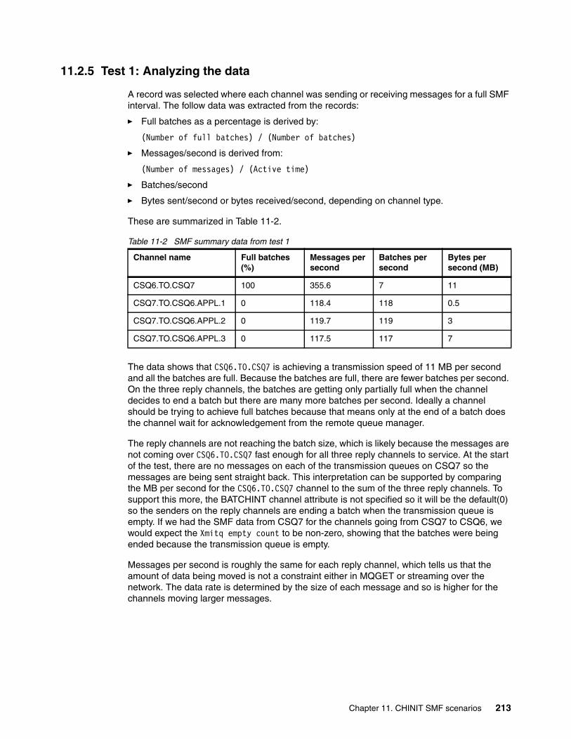
11.2.5 Test 1: Analyzing the data
A record was selected where each channel was sending or receiving messages for a full SMF interval. The follow data was extracted from the records:
� Full batches as a percentage is derived by:
(Number of full batches) / (Number of batches)
� Messages/second is derived from:
(Number of messages) / (Active time)
� Batches/second
� Bytes sent/second or bytes received/second, depending on channel type.
These are summarized in Table 11-2.
Table 11-2 SMF summary data from test 1
The data shows that CSQ6.TO.CSQ7 is achieving a transmission speed of 11 MB per second and all the batches are full. Because the batches are full, there are fewer batches per second. On the three reply channels, the batches are getting only partially full when the channel decides to end a batch but there are many more batches per second. Ideally a channel should be trying to achieve full batches because that means only at the end of a batch does the channel wait for acknowledgement from the remote queue manager.
The reply channels are not reaching the batch size, which is likely because the messages are not coming over CSQ6.TO.CSQ7 fast enough for all three reply channels to service. At the start of the test, there are no messages on each of the transmission queues on CSQ7 so the messages are being sent straight back. This interpretation can be supported by comparing the MB per second for the CSQ6.TO.CSQ7 channel to the sum of the three reply channels. To support this more, the BATCHINT channel attribute is not specified so it will be the default(0) so the senders on the reply channels are ending a batch when the transmission queue is empty. If we had the SMF data from CSQ7 for the channels going from CSQ7 to CSQ6, we would expect the Xmitq empty count to be non-zero, showing that the batches were being ended because the transmission queue is empty.
Messages per second is roughly the same for each reply channel, which tells us that the amount of data being moved is not a constraint either in MQGET or streaming over the network. The data rate is determined by the size of each message and so is higher for the channels moving larger messages.
Channel name Full batches (%)
Messages per second
Batches per second
Bytes per second (MB)
CSQ6.TO.CSQ7 100 355.6 7 11
CSQ7.TO.CSQ6.APPL.1 0 118.4 118 0.5
CSQ7.TO.CSQ6.APPL.2 0 119.7 119 3
CSQ7.TO.CSQ6.APPL.3 0 117.5 117 7
Chapter 11. CHINIT SMF scenarios 213

11.2.6 Test 2: Configuration
Figure 11-10 shows the configuration for this scenario.
Figure 11-10 The configuration for scenario 1, test 2
In this test, three channels go from queue manager CSQ6 to CSQ7 instead of funneling the messages down one channel. Each channel pair takes a set size of message; 4 KB, 32 KB, or 64 KB.
Example 11-4 and Example 11-5 on page 216 each list a job that uses the MQ CSQUTIL utility to create this test configuration. The channels from CSQ7 are triggered so that when a message is put on the appropriate transmission queue, the channel starts.
Example 11-4 Job to configure scenario 1, test 2 on CSQ6
//MARKSCN1 JOB MSGCLASS=H,NOTIFY=&SYSUID /*JOBPARM SYSAFF=SC61 //SETUPQM6 EXEC PGM=CSQUTIL,PARM='CSQ6' //STEPLIB DD DSN=MQ800.SCSQANLE,DISP=SHR // DD DSN=MQ800.SCSQAUTH,DISP=SHR //SYSPRINT DD SYSOUT=* //SYSIN DD * COMMAND DDNAME(CMDINP) //CMDINP DD * ALTER QMGR STATCHL(HIGH) DEFINE QR(Q.FOR.APPL.1) + RNAME(Q.FOR.APPL.1) + RQMNAME(CSQ7) + XMITQ(APPL.1.XMIT) +
214 IBM MQ V8 Features and Enhancements

REPLACE DEFINE QR(Q.FOR.APPL.2) + RNAME(Q.FOR.APPL.2) + RQMNAME(CSQ7) + XMITQ(APPL.2.XMIT) + REPLACE DEFINE QR(Q.FOR.APPL.3) + RNAME(Q.FOR.APPL.3) + RQMNAME(CSQ7) + XMITQ(APPL.3.XMIT) + REPLACE DEFINE CHANNEL(CSQ6.TO.CSQ7.APPL.1) + CHLTYPE(SDR) + TRPTYPE(TCP) + XMITQ(APPL.1.XMIT) + CONNAME('WTSC62(1507)') + BATCHLIM(0) + REPLACE DEFINE CHANNEL(CSQ6.TO.CSQ7.APPL.2) + CHLTYPE(SDR) + TRPTYPE(TCP) + XMITQ(APPL.2.XMIT) + CONNAME('WTSC62(1507)') + BATCHLIM(0) + REPLACE DEFINE CHANNEL(CSQ6.TO.CSQ7.APPL.3) + CHLTYPE(SDR) + TRPTYPE(TCP) + XMITQ(APPL.3.XMIT) + CONNAME('WTSC62(1507)') + BATCHLIM(0) + REPLACE
DEFINE QL(APPL.1.XMIT) + USAGE(XMITQ) + REPLACE DEFINE QL(APPL.2.XMIT) + USAGE(XMITQ) + REPLACE DEFINE QL(APPL.3.XMIT) + USAGE(XMITQ) + REPLACE DEFINE QL(Q.FOR.APPL.1A) DEFINE QL(Q.FOR.APPL.2A) DEFINE QL(Q.FOR.APPL.2A) DEFINE CHANNEL(CSQ7.TO.CSQ6.APPL.1) + CHLTYPE(RCVR) + TRPTYPE(TCP) + REPLACE
Chapter 11. CHINIT SMF scenarios 215

DEFINE CHANNEL(CSQ7.TO.CSQ6.APPL.2) + CHLTYPE(RCVR) + TRPTYPE(TCP) + REPLACE DEFINE CHANNEL(CSQ7.TO.CSQ6.APPL.3) + CHLTYPE(RCVR) + TRPTYPE(TCP) + REPLACE //*
Example 11-5 Job to configure the alternative to scenario 1 on CSQ7
//MARKSCN2 JOB MSGCLASS=H,NOTIFY=&SYSUID /*JOBPARM SYSAFF=SC62 //SETUPQM7 EXEC PGM=CSQUTIL,PARM='CSQ7' //STEPLIB DD DSN=MQ800.SCSQANLE,DISP=SHR// DD DSN=MQ800.SCSQAUTH,DISP=SHR//SYSPRINT DD SYSOUT=* //SYSIN DD * COMMAND DDNAME(CMDINP) //CMDINP DD * DEFINE QR(Q.FOR.APPL.1) + RNAME(Q.FOR.APPL.1) + RQMNAME(CSQ6) + XMITQ(APPL.1.XMIT) + REPLACE DEFINE QR(Q.FOR.APPL.2) + RNAME(Q.FOR.APPL.2) + RQMNAME(CSQ6) + XMITQ(APPL.2.XMIT) + REPLACE DEFINE QR(Q.FOR.APPL.3) + RNAME(Q.FOR.APPL.3) + RQMNAME(CSQ6) + XMITQ(APPL.3.XMIT) + REPLACE DEFINE CHANNEL(CSQ7.TO.CSQ6.APPL.1) + CHLTYPE(SDR) + TRPTYPE(TCP) + XMITQ(APPL.1.XMIT) + CONNAME('WTSC61(1506)') + BATCHLIM(0) + REPLACE DEFINE CHANNEL(CSQ7.TO.CSQ6.APPL.2) + CHLTYPE(SDR) + TRPTYPE(TCP) + XMITQ(APPL.2.XMIT) + CONNAME('WTSC61(1506)') + BATCHLIM(0) + REPLACE DEFINE CHANNEL(CSQ7.TO.CSQ6.APPL.3) + CHLTYPE(SDR) + TRPTYPE(TCP) +
216 IBM MQ V8 Features and Enhancements

XMITQ(APPL.3.XMIT) + CONNAME('WTSC61(1506)') + BATCHLIM(0) + REPLACE DEFINE QL(APPL.1.XMIT) + USAGE(XMITQ) + INITQ(SYSTEM.CHANNEL.INITQ) + TRIGGER + TRIGDATA(CSQ7.TO.CSQ6.APPL.1) + REPLACE DEFINE QL(APPL.2.XMIT) + USAGE(XMITQ) + INITQ(SYSTEM.CHANNEL.INITQ) + TRIGGER + TRIGDATA(CSQ7.TO.CSQ6.APPL.2) + REPLACE DEFINE QL(APPL.3.XMIT) + USAGE(XMITQ) + INITQ(SYSTEM.CHANNEL.INITQ) + TRIGGER + TRIGDATA(CSQ7.TO.CSQ6.APPL.3) + REPLACE DEFINE CHANNEL(CSQ6.TO.CSQ7) + CHLTYPE(RCVR) + TRPTYPE(TCP) + REPLACE //*
11.2.7 Test 2: Analyzing the data
This test was run in the same way as test 1 (described in 11.2.3, “Running and capturing SMF” on page 207). Table 11-3 shows the results summary, constructed in the same way as Table 11-2 on page 213.
Table 11-3 SMF summary data from test 2
The results show that the channels from CSQ6 to CSQ7 are sending full batches most of the time. These send fewer batches per second but each batch is fuller. When the bytes per second is totalled for channels CSQ6.TO.CSQ7.APPL.1, CSQ6.TO.CSQ7.APPL.2, and CSQ6.TO.CSQ7.APPL.3 the rate is 27 MB per second.
Channel Name Full Batches (%)
Messages per Second
Batches per Second
Bytes per second (MB)
CSQ6.TO.CSQ7.APPL.1 99 7,932.5 157 11
CSQ6.TO.CSQ7.APPL.2 100 251.6 5 7
CSQ6.TO.CSQ7.APPL.3 100 146.8 2 9
CSQ7.TO.CSQ6.APPL.1 81.5 7,902.7 192 11
CSQ7.TO.CSQ6.APPL.2 0 219.6 251 7
CSQ7.TO.CSQ6.APPL.3 0 146.8 146 9
Chapter 11. CHINIT SMF scenarios 217

11.2.8 Conclusions
In this scenario, the CHINIT SMF data shows that using multiple channels achieves a higher overall transfer rate. This does not mean that multiple channels should always be employed. A busy channel is more efficient, but a small increase in load can lead to messages queuing on the transmission queue, and so increased latency for messages.
Before the MQ configuration is changed, other factors must be investigated. For example, is the channel transferring data at or near the maximum that the link can manage? Other system options can possibly be altered to enable the link to run quicker.
This SMF data can be interpreted to give the opposite conclusion. Is the channel throughput is low for each channel? This might indicate that one channel can be used to have the same throughput but use fewer resources, for example only the memory footprint of one channel.
Using SMF is like a science experiment. Altering one variable can give a different result so many experiments might be required to produce a better configuration. One factor might be the time of day; the system can have busy and quiet periods that affect the SMF data.
11.2.9 Further analysis that might be required
CHINIT SMF gives the MQ administrator a view into only the CHINIT performance. The performance of other components might have an impact. The queue manager might need tuning to improve MQGET or MQPUT rates, and network software might need tuning to improve communication link performance.
11.3 Scenario 2: Varying the number of adapters
The second scenario shows the effect of varying the number of adapter tasks in the CHINIT.
The channel initiator’s address space has two main types of tasks:
� Dispatchers: Carry out all the communication APIs for a channel; many channels can run on a single dispatcher.
� Adapters: Carry out the MQ API work for a channel. They are not tied to a single channel so they are used when an MQ API call is required, for example a MQGET.
11.3.1 Objectives of scenario
This scenario demonstrates use of the SMF statistics data that is produced by the CHINIT. The CHINIT produces statistics data for all the major tasks in the address space. This scenario looks only at the adapters task. Not all SMF data for the adapters is used because, depending on the scenario, different fields will be analyzed.
Results from four tests are shown. Each test runs the same workload, but the only variant among the four tests is the number of adapters that are configured.
The role of adapters When a channel wants to call into the queue manger, a request is made. The request takes the first available adapter task. The role of the adapter is to make the call into the queue manager and wait for the response. After the response is passed back to the channel, the adapter task waits for the next request from any active channel.
218 IBM MQ V8 Features and Enhancements

The default number of adapters is eight but this can be changed by the MQ administrator. The following command alters the number of adapters:
-CSQ6 ALTER QMGR CHIADAPS(number)
The CHINIT uses only the CHIADAPS value when the address space is started. If the value is altered, the CHINIT must be stopped and restarted to pick up the new CHIADAPS value.
If the number of adapters is too many, the result is a waste of system resources because some adapters will not get any work to do.
If the number of adapters is too few, requests will be queued internally, waiting for an adapter to become available to process the next request. This leads to delays and the throughput is affected. The suggested approach is for one adapter to be available if the rest are busy. This allows it to be used by other channels that are not processing workload, for example the MQ Explorer might be used to determine the channel statuses.
11.3.2 Set-up and method
This scenario was deliberately engineered to put a high load on the adapters. The aim of this scenario is to show any difference as the number of adapters changes, given the same workload. The adapter statistics are used to demonstrate the findings.
A queue named JUNGLE was defined on the queue manager CSQ6 with the following command:
-CSQ6 DEFINE QLOCAL(JUNGLE) SHARE DEFSOPT(SHARED)
Small messages (5,008) were put on the queue with a property called Animal set. The messages are allocated as follows:
� 5,000 with Animal=Monkey � 1 with Animal=Elephant � 1 with Animal=Lion � 1 with Animal=Tiger � 1 with Animal=Giraffe � 1 with Animal=Rhinoceros � 1 with Animal=Cheetah � 1 with Animal=Lynx � 1 with Animal=Leopard
A Java Message Service (JMS) client application was created that does a get operation with a selector for the message property Animal. The type of animal is supplied to the application through the command line. Because a queue cannot be indexed by properties, each message on the queue must be viewed in turn to determine whether it matches the selector. This API is CPU-intensive. Example 11-6 on page 220 shows the application’s main logic.
Chapter 11. CHINIT SMF scenarios 219

Example 11-6 The main logic of the application used in scenario 2
// Continue for 5 minuteslong endTime = System.currentTimeMillis() + (5 * 60 * 1000);while (System.currentTimeMillis() < endTime){ // Receive message message = consumer.receiveNoWait(); if (message != null) { // Put the message back on queue producer.send(message); }}
The application runs for 5 minutes. Twenty instances of the client application were run in parallel using a mixture of the different animals listed, apart from Monkey. The application has a loop that repeats for 5 minutes. For each iteration, a MQGET with a selector is done, and the message that is received is put back on the queue.
All the client applications were run on the same client machine.
The system that was used to test this scenario had only two CPUs so the number of adapters tested varied from one to eight adapters. The following configurations were tested:
� Test 1: 1 adapter� Test 2: 2 adapters� Test 3: 4 adapters� Test 4: 8 adapters
The data that is shown in this scenario was taken in a full SMF interval. when all the application instances were processing messages. The statistics gathering interval (STATIME) was set to 1, so records were cut every minute. The following command was run to start the statistics SMF trace in the CHINIT:
-CSQ6 START TRACE(STAT) CLASS(4)
11.3.3 Running the test
The test is started by running a shell script, which started 20 instances of the JMS client at the same time. Although the client application runs for 5 minutes, the length of time to start and finish all instances is longer but there was a time when all 20 instances were running concurrently.
The scenario was kept running for at least one complete SMF interval. The interval does not start when the start trace command is issued so allow one interval for the start point to be reached. After the required time elapses the job, shown in Figure 11-7 on page 210, can be submitted. This job is described in “Capturing the SMF data” on page 209.
Because the SMF data was collected, the following command can be issued to stop the trace.
-CSQ6 STOP TRACE(STAT) CLASS(4)
220 IBM MQ V8 Features and Enhancements

11.3.4 Formatting the SMF data
The job listed in Example 11-1 is the JCL to run the MQSMF program. The program takes the SMF input through a data set, specified by the SMFIN DD card.
Example 11-7 Job to run MQSMF
//CSQ6SMFD JOB NOTIFY=&SYSUID,REGION=0M//SAMPSTEP EXEC PGM=MQSMF,REGION=0M //STEPLIB DD DSN=ELKINSC.MP1B.D13JUN.LOAD,DISP=SHR //SMFIN DD DISP=SHR,DSN=MARKW1.SMFCSQ6.JUNE18B.OUT //SYSPRINT DD SYSOUT=*,DCB=(LRECL=132,RECFM=F) //MESSAGE DD SYSOUT=* //CMESSAGE DD SYSOUT=* //ADAPS DD SYSOUT=* ...//
The JCL shows the DD cards that relate to messages produced by MP1B or the data required for this scenario (ADAPS).
Figure 11-11 shows the adapter report for one SMF interval that was formatted from MP1B.
Figure 11-11 Sample adapter report from MP1B
Not all data on the MP1B adapter report was used in this scenario; depending on what is being measured determines what data is required. The fields that are relevant to this are circled in Figure 11-11.
� Task is the adapter number. It is derived from the order of records in the SMF record and corresponds with the order that the CHINIT searches for a free adapter to process the request.
� Busy % is the percentage of the interval that the adapter spent processing API requests. It is obtained from qcteltm and duration.
� Avg CPU is the average CPU time for each request to complete, in microseconds. It is obtained from the qctcptm and qctreqn average.
� Avg ET is the average elapsed time for each request to complete, in microseconds, including any time that the request is waiting, for example for locks. The value is obtained from qcteltm and qctreqn.
At the bottom of the report, a summary line indicates the data for each adapter combined.
SC61,CSQ6,2014/06/26,04:44:16,VRM:800, From 2014/06/26,04:43:15.820238 to 2014/06/26,04:44:16.637491 duration 60.817252 secondsTask,Type,Requests,Busy %, CPU used, CPU %,"avg CPU","avg ET" , , , , Seconds, , uSeconds,uSeconds 0,ADAP, 3601, 64.1, 20.407477, 34.0, 5667, 10679 1,ADAP, 2609, 55.4, 15.429918, 25.7, 5914, 12729 2,ADAP, 1994, 47.2, 12.188188, 20.3, 6112, 14210 3,ADAP, 1473, 39.5, 9.183473, 15.3, 6235, 16079 4,ADAP, 1066, 31.9, 6.703570, 11.2, 6289, 17981 5,ADAP, 776, 25.0, 4.913395, 8.2, 6332, 19346 6,ADAP, 512, 17.6, 3.254708, 5.4, 6357, 20657 7,ADAP, 330, 12.0, 2.098817, 3.5, 6360, 21869 Summ,ADAP, 12361, 36.6, 74.179547, 15.5, 6001, 14211
Chapter 11. CHINIT SMF scenarios 221

11.3.5 Analyzing the data
In this section, the results for each test are shown and discussed.
Test 1: One adapterIn this test, the number of adapters was configured to 1. The graph in Figure 11-12 shows the percentage busy for one adapter over the period.
Figure 11-12 Graph showing the adapter busy percentage for one adapter over the time period.
Figure 11-13 shows the output of the MP1B adapter report for One-Stats interval, in the middle of the test.
Figure 11-13 Adapter report output for one stats interval, when only running 1 adapter.
The graph and the adapter report show the adapter is running at 100%. Also, the average CPU time is close to the elapsed time, which means that each request is not being blocked by other tasks in the system.
SC61,CSQ6,2014/06/26,05:52:11,VRM:800, From 2014/06/26,05:51:10.590377 to 2014/06/26,05:52:11.407791 duration 60.817413 secondsTask,Type,Requests,Busy %, CPU used, CPU %,"avg CPU","avg ET" , , , , Seconds, , uSeconds,uSeconds 0,ADAP, 11978, 101.2, 59.541750, 99.2, 4971, 5068 Summ,ADAP, 11978, 101.2, 59.541750, 99.2, 4971, 5068
Note: At time of writing, the percentage busy was found to be over 100% busy. This was verified with the author of MP1B.
222 IBM MQ V8 Features and Enhancements

Test 2: Two adapters In this test, the number of adapters was configured to 2. This is the same as the number of CPUs defined for the LPAR to use. The graph in Figure 11-14 shows the percentage busy for two adapters over the period.
Figure 11-14 Graph showing the adapter busy percentage for two adapters over the time period
Although this graph appears to show only one line, both lines follow the same path and so are overlaid.
Figure 11-15 shows the output of the MP1B adapter report for one stats interval, in the middle of this test.
Figure 11-15 Adapter report output for one stats interval, when only running 2 adapters
The data shows that both adapters are busy. Also a larger difference exists between the average CPU time and the average elapsed time so a request is taking approximately double the actual CPU time to complete. The probable reason is that all the requests are looking at the same queue so all the required resources are the same.
SC61,CSQ6,2014/06/26,05:24:49,VRM:800, From 2014/06/26,05:23:48.518517 to 2014/06/26,05:24:49.335945 duration 60.817427 secondsTask,Type,Requests,Busy %, CPU used, CPU %,"avg CPU","avg ET" , , , , Seconds, , uSeconds,uSeconds 0,ADAP, 6490, 98.9, 34.018854, 56.7, 5242, 9147 1,ADAP, 6461, 98.9, 33.849555, 56.4, 5239, 9185 Summ,ADAP, 12951, 98.9, 67.868409, 56.6, 5240, 9166
Chapter 11. CHINIT SMF scenarios 223

Test 3: Four adapters In this third test, the number of adapter tasks running in the CHINIT is configured to 4. The graph in Figure 11-16 shows the percentage busy for four adapters over the period.
Figure 11-16 Graph showing the adapter busy percentage for four adapters over the time period
Figure 11-17 shows the output of the MP1B adapter report for one stats interval, in the middle of this test.
Figure 11-17 Adapter report output for one stats interval, when only running 4 adapters
The data with four adapters shows that the adapter busy percentage decreased to approximately 50% and the total number of requests processed in the interval increased, compared to using two adapters as shown in Figure 11-14 on page 223. The graph shows that the higher the adapter number, the fewer requests it receives as the work is allocated to the first free adapter. This behavior is normal and is the way that the channel initiator is designed.
From 2014/06/26,04:59:28.899438 to 2014/06/26,05:00:29.716843 duration 60.817404 secondsTask,Type,Requests,Busy %, CPU used, CPU %,"avg CPU","avg ET" , , , , Seconds, , uSeconds,uSeconds 0,ADAP, 5196, 73.3, 28.532417, 47.6, 5491, 8465 1,ADAP, 4040, 62.8, 22.742098, 37.9, 5629, 9328 2,ADAP, 2700, 45.6, 15.772872, 26.3, 5842, 10127 3,ADAP, 1254, 23.3, 7.546442, 12.6, 6018, 11128 Summ,ADAP, 13190, 51.2, 74.593829, 31.1, 5655, 9323
224 IBM MQ V8 Features and Enhancements

Test 4: Eight adapters The final test was to use eight adapters, which is the default number of adapters that is included with IBM MQ. This is four adapters per CPU that the test LPAR is defined for the LPAR to use. The graph in Figure 11-18 shows the percentage busy for eight adapters over the period.
Figure 11-18 Graph showing the adapter busy percentage for eight adapters over the time period
Figure 11-19 shows the output of the MP1B adapter report for one stats interval, in the middle of this test.
Figure 11-19 Adapter report output for one stats interval, when running eight adapters
The data with eight adapters shows that the adapter busy percentage is lower than the other tests, with the average of 36.6%. It also shows that the adapters that have the lower adapter number have more requests. This behavior is expected because, when a request is made for an adapter, the first free adapter is used. The average elapsed time is double and sometimes triple the average CPU time. This is likely to be accounted for because more workers are processing work in parallel and requiring the same resources.
SC61,CSQ6,2014/06/26,04:44:16,VRM:800, From 2014/06/26,04:43:15.820238 to 2014/06/26,04:44:16.637491 duration 60.817252 secondsTask,Type,Requests,Busy %, CPU used, CPU %,"avg CPU","avg ET" , , , , Seconds, , uSeconds,uSeconds 0,ADAP, 3601, 64.1, 20.407477, 34.0, 5667, 10679 1,ADAP, 2609, 55.4, 15.429918, 25.7, 5914, 12729 2,ADAP, 1994, 47.2, 12.188188, 20.3, 6112, 14210 3,ADAP, 1473, 39.5, 9.183473, 15.3, 6235, 16079 4,ADAP, 1066, 31.9, 6.703570, 11.2, 6289, 17981 5,ADAP, 776, 25.0, 4.913395, 8.2, 6332, 19346 6,ADAP, 512, 17.6, 3.254708, 5.4, 6357, 20657 7,ADAP, 330, 12.0, 2.098817, 3.5, 6360, 21869 Summ,ADAP, 12361, 36.6, 74.179547, 15.5, 6001, 14211
Chapter 11. CHINIT SMF scenarios 225
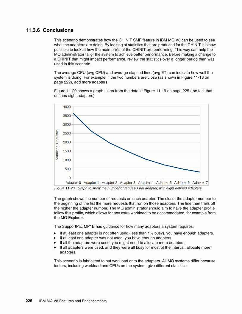
11.3.6 Conclusions
This scenario demonstrates how the CHINIT SMF feature in IBM MQ V8 can be used to see what the adapters are doing. By looking at statistics that are produced for the CHINIT it is now possible to look at how the main parts of the CHINIT are performing. This way can help the MQ administrator tailor the system to achieve better performance. Before making a change to a CHINIT that might impact performance, review the statistics over a longer period than was used in this scenario.
The average CPU (avg CPU) and average elapsed time (avg ET) can indicate how well the system is doing. For example, if the two numbers are close (as shown in Figure 11-13 on page 222), add more adapters.
Figure 11-20 shows a graph taken from the data in Figure 11-19 on page 225 (the test that defines eight adapters).
Figure 11-20 Graph to show the number of requests per adapter, with eight defined adapters
The graph shows the number of requests on each adapter. The closer the adapter number to the beginning of the list the more requests that run on those adapters. The line then trails off the higher the adapter number. The MQ administrator should aim to have the adapter profile follow this profile, which allows for any extra workload to be accommodated, for example from the MQ Explorer.
The SupportPac MP1B has guidance for how many adapters a system requires:
� If at least one adapter is not often used (less than 1% busy), you have enough adapters. � If at least one adapter was not used, you have enough adapters. � If all the adapters were used, you might need to allocate more adapters. � If all adapters were used, and they were all busy for most of the interval, allocate more
adapters.
This scenario is fabricated to put workload onto the adapters. All MQ systems differ because factors, including workload and CPUs on the system, give different statistics.
226 IBM MQ V8 Features and Enhancements
Chapter 12. Advantages of a buffer pool above the bar
This chapter presents a simple scenario showing how buffer pools above the bar can benefit an application where the queues can become deep. In the real world these conditions occur when the getting application is unavailable or cannot keep up with the putting application.
These simple tests are not intended to replace the results from the formal MQ for z/OS performance report (tentatively named MP1J). They are intended to be a simple demonstration of how effective the larger buffer pools can be and a guide for tests that you may want to run in your environment.
This chapter contains the following topics:
� 12.1, “System set-up” on page 228
� 12.2, “Test application” on page 229
� 12.3, “Test 1: Buffer pool below the bar, nonpersistent messages, no I/O” on page 231
� 12.4, “Test 2: Buffer pool above the bar, nonpersistent messages, no I/O” on page 233
� 12.5, “Test 3: Buffer pool below the bar, nonpersistent messages, I/O expected” on page 235
� 12.6, “Test 4: Buffer pool above the bar, nonpersistent messages” on page 238
� 12.7, “Test 5: Buffer pool below the bar, persistent messages” on page 240
� 12.8, “Test 6: Buffer pool above the bar, persistent messages” on page 242
� 12.9, “Test 7: Buffer pool above the bar, persistent messages, fixed pages” on page 244
� 12.10, “Test 8: Buffer pool below the bar, nonpersistent messages, I/O expected” on page 247
� 12.11, “Test 9: Buffer pool above the bar, nonpersistent messages, I/O expected” on page 249
� 12.12, “Test comparisons” on page 251
� 12.13, “Summary” on page 254
12
© Copyright IBM Corp. 2014. All rights reserved. 227

12.1 System set-up
The environment is simple: a single z/OS queue manager was used. The queue manager was defined with buffer pools above and below the bar. The buffered and page set definitions are shown in Example 12-1.
Example 12-1 Buffer pool and page set definitions
Buffer pool definitions:DEFINE BUFFPOOL( 0 ) BUFFERS( 20000 ) LOCATION( BELOW ) + PAGECLAS( 4KB ) NOREPLACE DEFINE BUFFPOOL( 1 ) BUFFERS( 50000 ) LOCATION( BELOW ) + PAGECLAS( 4KB ) NOREPLACE DEFINE BUFFPOOL( 2 ) BUFFERS( 20000 ) LOCATION( BELOW ) + PAGECLAS( 4KB ) NOREPLACE DEFINE BUFFPOOL( 3 ) BUFFERS( 50000 ) LOCATION( BELOW ) + PAGECLAS( 4KB ) NOREPLACE DEFINE BUFFPOOL( 4 ) BUFFERS( 20000 ) LOCATION( BELOW ) + PAGECLAS( 4KB ) NOREPLACE DEFINE BUFFPOOL( 20) BUFFERS( 20000 ) LOCATION( ABOVE ) + PAGECLAS( 4KB ) NOREPLACE DEFINE BUFFPOOL( 21) BUFFERS( 100000 ) LOCATION( ABOVE ) + PAGECLAS( 4KB ) NOREPLACE
Pageset Definitions:DEFINE PSID( 00 ) BUFFPOOL( 0 ) EXPAND ( USER ) DEFINE PSID( 01 ) BUFFPOOL( 1 ) EXPAND ( USER ) DEFINE PSID( 02 ) BUFFPOOL( 2 ) EXPAND ( USER ) DEFINE PSID( 03 ) BUFFPOOL( 3 ) EXPAND ( USER ) DEFINE PSID( 04 ) BUFFPOOL( 4 ) EXPAND ( USER ) DEFINE PSID( 20 ) BUFFPOOL( 20 ) EXPAND ( USER ) DEFINE PSID( 21 ) BUFFPOOL( 21 ) EXPAND ( USER )
Storage classes corresponding to the page sets were defined as shown in Example 12-2.
Example 12-2 Storage class definitions
Storage class definitions:DEFINE STGCLASS( 'PS01' ) + QSGDISP( QMGR ) + PSID( 01 ) DEFINE STGCLASS( 'PS02' ) + QSGDISP( QMGR ) + PSID( 02 ) DEFINE STGCLASS( 'PS03' ) + QSGDISP( QMGR ) + PSID( 03 ) DEFINE STGCLASS( 'PS04' ) + QSGDISP( QMGR ) + PSID( 04) DEFINE STGCLASS( 'PS20' ) + QSGDISP( QMGR ) + PSID( 20 ) DEFINE STGCLASS( 'PS21' ) + QSGDISP( QMGR ) + PSID( 21 )
228 IBM MQ V8 Features and Enhancements

Four queues were used during these tests. The first pair (CSQ4.LOCAL.PS03 and CSQ4.LOCAL.PS21) was used to compare the effects of I/O in the smaller below-the-bar buffer pool and no I/O in the larger above-the-bar pool. Their storage class attributes are shown in Example 12-3.
Example 12-3 Queue definitions
Queue definitions:07.28.44 STC18408 CSQM201I -CSQ4 CSQMDRTC DISPLAY QLOCAL DETAILS 019 019 QUEUE(CSQ4.LOCAL.PS03) 019 TYPE(QLOCAL) 019 QSGDISP(QMGR) 019 STGCLASS(PS03) 019 END QLOCAL DETAILS 07.28.44 STC18408 CSQ9022I -CSQ4 CSQMDRTC ' DISPLAY QLOCAL' NORMAL COMPLETION
07.29.23 STC18408 CSQM201I -CSQ4 CSQMDRTC DISPLAY QLOCAL DETAILS 023 023 QUEUE(CSQ4.LOCAL.PS21) 023 TYPE(QLOCAL) 023 QSGDISP(QMGR) 023 STGCLASS(PS21) 023 END QLOCAL DETAILS 07.29.23 STC18408 CSQ9022I -CSQ4 CSQMDRTC ' DISPLAY QLOCAL' NORMAL COMPLETION
The second pair (CSQ4.LOCAL.PS04 and CSQ4.LOCAL.PS20) was used to compare buffer pools below and above the bar when I/O is required for both. The storage class attributes are shown in Example 12-4.
Example 12-4 Queue definitions with storage class
09.09.30 STC20604 CSQM201I -CSQ4 CSQMDRTC DISPLAY QLOCAL DETAILS 546 546 QUEUE(CSQ4.LOCAL.PS04) 546 TYPE(QLOCAL) 546 QSGDISP(QMGR) 546 STGCLASS(PS04) 546 END QLOCAL DETAILS 09.09.30 STC20604 CSQ9022I -CSQ4 CSQMDRTC ' DISPLAY QLOCAL' NORMAL COMPLETION 09.18.57 STC20604 CSQM201I -CSQ4 CSQMDRTC DISPLAY QLOCAL DETAILS 561 561 QUEUE(CSQ4.LOCAL.PS20) 561 TYPE(QLOCAL) 561 QSGDISP(QMGR) 561 STGCLASS(PS20) 561 END QLOCAL DETAILS 09.18.57 STC20604 CSQ9022I -CSQ4 CSQMDRTC ' DISPLAY QLOCAL' NORMAL COMPLETION
12.2 Test application
For the tests run, the OEMPUTX program was used. This sample program was delivered with a now obsolete WebSphere Message Broker SupportPac IP13. The program is so useful it is being brought back for MQ, and will be delivered with an updated version of MP1B, MQ for z/OS V8.01 - Interpreting accounting and statistics data. (The version number refers to the level of MP1B, not of MQ.)
Any application program or programs can be used to load and then get messages from a queue can be used to replicate this test in your environment. The sample programs amqsputc and amqsgetc could easily be used.
Chapter 12. Advantages of a buffer pool above the bar 229

A sample of the JCL to test the put process for the CSQ4.LOCAL.PS03 queue is shown in Example 12-5.
Example 12-5 OEMPUTX sample JCL to put messages on CSQ4.LOCAL.PS03
//ELKINSCP JOB NOTIFY=&SYSUID/*JOBPARM S=SC62//PROCLIB JCLLIB ORDER=(ELKINSC.ZOS.JCL)// SET STEPLIB=WMQICPV6// SET APPLOAD='ELKINSC.IP13.LOAD'// SET MQLOAD1='MQ800.SCSQLOAD'// SET MQLOAD2='MQ800.SCSQAUTH'// SET MQLOAD3='MQ800.SCSQLOAD'// SET THISPDS='ELKINSC.ZOS.JCL'// SET QM='CSQ4'// SET SUMMARY='TEAMXX.DOCUMENT.SUMMARY'// SET DB2='DSNA*' DB2 NAME USED IN REPORTING CPU//* THE FILE IN TEMPFILE GETS DELETED AND CREATED IN JTEST0// SET TEMPFILE='TEAMXX.ZZ2'// SET P=' ' NONPERSISTENT MESSAGES// SET MSGS=55000 MESSAGES ONLY//*// EXEC PGM=OEMPUTX,REGION=0M,// PARM=('-m&QM. -n&MSGS. -x &P. -l1 -c1 -cgcpc -s3072 ')//SYSIN DD *-QCSQ4.LOCAL.PS03-FILEDD:MSGIN-DJTEST4//STEPLIB DD DISP=SHR,DSN=&APPLOAD.// DD DISP=SHR,DSN=&MQLOAD1.// DD DISP=SHR,DSN=&MQLOAD2.// DD DISP=SHR,DSN=&MQLOAD3.//MSGIN DD DISP=SHR,DSN=&THISPDS.(SMALMSG)//SYSPRINT DD SYSOUT=*//
A sample of the JCL to get the messages from the queue is shown in Example 12-6.
Example 12-6 OEMPUX sample to get messages from CSQ4.LOCAL.PS03
//ELKINSCP JOB NOTIFY=&SYSUID/*JOBPARM S=SC62//PROCLIB JCLLIB ORDER=(ELKINSC.ZOS.JCL)// SET STEPLIB=WMQICPV6// SET APPLOAD='ELKINSC.IP13.LOAD'// SET MQLOAD1='MQ800.SCSQLOAD'// SET MQLOAD2='MQ800.SCSQAUTH'// SET MQLOAD3='MQ800.SCSQLOAD'// SET THISPDS='ELKINSC.ZOS.JCL'// SET QM='CSQ4'// SET SUMMARY='TEAMXX.DOCUMENT.SUMMARY'// SET DB2='DSNA*' DB2 NAME USED IN REPORTING CPU//* THE FILE IN TEMPFILE GETS DELETED AND CREATED IN JTEST0// SET TEMPFILE='TEAMXX.ZZ2'// SET P=' ' NONPERSISTENT MESSAGES// SET MSGS=55000 MESSAGES ONLY//*// EXEC PGM=OEMPUTX,REGION=0M,// PARM=('-m&QM. -n&MSGS. -x &P. -l1 -c1 -cgcpc -s3072 ')//SYSIN DD *-rCSQ4.LOCAL.PS03
230 IBM MQ V8 Features and Enhancements

-FILEDD:MSGIN-DJTEST4//STEPLIB DD DISP=SHR,DSN=&APPLOAD.// DD DISP=SHR,DSN=&MQLOAD1.// DD DISP=SHR,DSN=&MQLOAD2.// DD DISP=SHR,DSN=&MQLOAD3.//MSGIN DD DISP=SHR,DSN=&THISPDS.(SMALMSG)//SYSPRINT DD SYSOUT=*//
In each put test the number of messages put to the queue was 20,000, 55,000 or 30,000, depending on what was being demonstrated. Each message was 3072 bytes long. In each get test, the queue was drained of messages. The larger number of messages (55,000) was chosen because the below-the-bar buffer pool did not hold all the messages, so page set I/O was be necessary.
To evaluate the results, the class 3 accounting records were captured and reports were generated using the MQSMF program from SuportPac MP1B. Beta reports were used so your results might differ from these.
If you try to determine whether a queue or queues can benefit from a larger buffer pool, review the MQ buffer pool statistics to determine whether I/O is occurring. If multiple queues are using the buffer pool during the time when I/O is taking place, examining the SMF 116 class 3 accounting records is necessary to determine whether the queue or queues that are being evaluated are reporting that I/O must be done on the get processing.
12.3 Test 1: Buffer pool below the bar, nonpersistent messages, no I/O
In the first test group, a limited number of messages (20,000) is being used to compare the CPU usage and elapsed time when using buffer pools that are below and above the bar, when no I/O occurs.
The results from the 20,000 messages put to the queue, using below-the-bar page sets, are shown in Example 12-7.
Example 12-7 Below the bar, no I/O put message results
15 SC62,CSQ4,2014/06/25,06:02:45,VRM:800, 15 CSQ4 Batch Jobname:ELKINSCP Userid:ELKINSC 15 Start time Jun 25 06:02:45 2014 Started this interval 15 Interval Jun 25 06:02:45 2014 - Jun 25 06:02:46 2014 : 0.755287 seconds 15 Other reqs : Count 1 15 Other reqs : Avg elapsed time 8 uS 15 Other reqs : Avg CPU 7 uS 15 Other reqs : Total ET 0.000008 Seconds 15 Other reqs : Total CPU 0.000007 Seconds 15 > Latch 16, Total wait 15151 uS, Waits 253, Name BMXL2 |RMCRMST |RLMARQC 15 > Latch 16, Avg wait 59 uS, Max 1968 uS, BMXL2 |RMCRMST |RLMARQC 15 Longest latch wait at 00000000254a86b0 15151 uS 15 Avg Latch time per UOW 0 uS 15 Commit count 20001 15 Commit avg elapsed time 14 uS 15 Commit avg CPU time 4 uS
Chapter 12. Advantages of a buffer pool above the bar 231

15 Suspend Count 19999 15 Suspend Avg elapsed time 9 uS 15 Total suspend time 0.197868 Seconds 15 Pages old 61111 15 Pages new 20278 15 Open name CSQ4.LOCAL.PS03 15 Queue type:QLocal CSQ4.LOCAL.PS03 15 Queue indexed by NONE CSQ4.LOCAL.PS03 15 First Opened Jun 25 06:02:45 2014 CSQ4.LOCAL.PS03 15 Last Closed Jun 25 06:02:46 2014 CSQ4.LOCAL.PS03 15 Page set ID 3 CSQ4.LOCAL.PS03 15 Buffer pool 3 CSQ4.LOCAL.PS03 15 Current opens 0 CSQ4.LOCAL.PS03 15 Total requests 20002 CSQ4.LOCAL.PS03 15 Open Count 1 CSQ4.LOCAL.PS03 15 Open Avg elapsed time 40 uS CSQ4.LOCAL.PS03 15 Open Avg CPU time 40 uS CSQ4.LOCAL.PS03 15 Close count 1 CSQ4.LOCAL.PS03 15 Close avg elapsed time 11 uS CSQ4.LOCAL.PS03 15 Close avg CPU time 11 uS CSQ4.LOCAL.PS03 15 Put count 20000 CSQ4.LOCAL.PS03 15 Put avg elapsed time 17 uS CSQ4.LOCAL.PS03 15 Put avg CPU time 16 uS CSQ4.LOCAL.PS03 15 Put suspended time 0 uS CSQ4.LOCAL.PS03 15 Put + put1 valid count 20000 CSQ4.LOCAL.PS03 15 Put size maximum 3072 CSQ4.LOCAL.PS03 15 Put size minimum 3072 CSQ4.LOCAL.PS03 15 Put size average 3072 CSQ4.LOCAL.PS03 15 Put num not peristent 20000 CSQ4.LOCAL.PS03 15 Curdepth maximum 20000 CSQ4.LOCAL.PS03 15 Total Queue elapsed time 357345 uS CSQ4.LOCAL.PS03 15 Total Queue CPU used 335111 uS CSQ4.LOCAL.PS03 15 Grand total CPU time 434563 uS 15 Grand Elapsed time 654343 uS
The second part of the initial test retrieved the messages from the queue. Example 12-8 shows the results.
Example 12-8 Below the bar, no I/O put message results
33 SC62,CSQ4,2014/06/25,06:03:17,VRM:800, 33 CSQ4 Batch Jobname:ELKINSCP Userid:ELKINSC 33 Start time Jun 25 06:03:17 2014 Started this interval 33 Interval Jun 25 06:03:17 2014 - Jun 25 06:03:18 2014 : 0.737702 seconds 33 Other reqs : Count 1 33 Other reqs : Avg elapsed time 7 uS 33 Other reqs : Avg CPU 7 uS 33 Other reqs : Total ET 0.000007 Seconds 33 Other reqs : Total CPU 0.000007 Seconds 33 Commit count 20001 33 Commit avg elapsed time 12 uS 33 Commit avg CPU time 4 uS 33 Suspend Count 20000 33 Suspend Avg elapsed time 7 uS 33 Total suspend time 0.158496 Seconds 33 Pages old 80277 33 Open name CSQ4.LOCAL.PS03 33 Queue type:QLocal CSQ4.LOCAL.PS03 33 Queue indexed by NONE CSQ4.LOCAL.PS03 33 First Opened Jun 25 06:03:17 2014 CSQ4.LOCAL.PS03
232 IBM MQ V8 Features and Enhancements

33 Last Closed Jun 25 06:03:18 2014 CSQ4.LOCAL.PS03 33 Page set ID 3 CSQ4.LOCAL.PS03 33 Buffer pool 3 CSQ4.LOCAL.PS03 33 Current opens 0 CSQ4.LOCAL.PS03 33 Total requests 20002 CSQ4.LOCAL.PS03 33 Open Count 1 CSQ4.LOCAL.PS03 33 Open Avg elapsed time 43 uS CSQ4.LOCAL.PS03 33 Open Avg CPU time 43 uS CSQ4.LOCAL.PS03 33 Close count 1 CSQ4.LOCAL.PS03 33 Close avg elapsed time 10 uS CSQ4.LOCAL.PS03 33 Close avg CPU time 10 uS CSQ4.LOCAL.PS03 33 Get count 20000 CSQ4.LOCAL.PS03 33 Get avg elapsed time 18 uS CSQ4.LOCAL.PS03 33 Get avg CPU time 18 uS CSQ4.LOCAL.PS03 33 Get total empty pages 277 CSQ4.LOCAL.PS03 33 Get TOQ average 32465999 uS CSQ4.LOCAL.PS03 33 Get TOQ maximum 32482526 uS CSQ4.LOCAL.PS03 33 Get TOQ minimum 32454063 uS CSQ4.LOCAL.PS03 33 Get valid count 20000 CSQ4.LOCAL.PS03 33 Get size maximum 3072 bytes CSQ4.LOCAL.PS03 33 Get size minimum 3072 bytes CSQ4.LOCAL.PS03 33 Get size average 3072 bytes CSQ4.LOCAL.PS03 33 Get Dest-Next 20000 CSQ4.LOCAL.PS03 33 Get not persistent count 20000 CSQ4.LOCAL.PS03 33 Curdepth maximum 19999 CSQ4.LOCAL.PS03 33 Total Queue elapsed time 368413 uS CSQ4.LOCAL.PS03 33 Total Queue CPU used 362438 uS CSQ4.LOCAL.PS03 33 Grand total CPU time 459664 uS 33 Grand Elapsed time 622053 uS
12.4 Test 2: Buffer pool above the bar, nonpersistent messages, no I/O
The results from the 20,000 messages put to the queue, using above-the-bar buffer pools, are shown in Example 12-9.
Example 12-9 Above the bar, no I/O put message results
34 SC62,CSQ4,2014/06/25,06:03:43,VRM:800, 34 CSQ4 Batch Jobname:ELKINSCP Userid:ELKINSC 34 Start time Jun 25 06:03:43 2014 Started this interval 34 Interval Jun 25 06:03:43 2014 - Jun 25 06:03:44 2014 : 0.696769 seconds 34 Other reqs : Count 1 34 Other reqs : Avg elapsed time 7 uS 34 Other reqs : Avg CPU 7 uS 34 Other reqs : Total ET 0.000007 Seconds 34 Other reqs : Total CPU 0.000007 Seconds 34 Commit count 20001 34 Commit avg elapsed time 13 uS 34 Commit avg CPU time 4 uS 34 Suspend Count 19998 34 Suspend Avg elapsed time 8 uS 34 Total suspend time 0.169749 Seconds 34 Pages old 61111 34 Pages new 20278 34 Open name CSQ4.LOCAL.PS21 34 Queue type:QLocal CSQ4.LOCAL.PS21
Chapter 12. Advantages of a buffer pool above the bar 233

34 Queue indexed by NONE CSQ4.LOCAL.PS21 34 First Opened Jun 25 06:03:43 2014 CSQ4.LOCAL.PS21 34 Last Closed Jun 25 06:03:44 2014 CSQ4.LOCAL.PS21 34 Page set ID 21 CSQ4.LOCAL.PS21 34 Buffer pool 21 CSQ4.LOCAL.PS21 34 Current opens 0 CSQ4.LOCAL.PS21 34 Total requests 20002 CSQ4.LOCAL.PS21 34 Open Count 1 CSQ4.LOCAL.PS21 34 Open Avg elapsed time 37 uS CSQ4.LOCAL.PS21 34 Open Avg CPU time 37 uS CSQ4.LOCAL.PS21 34 Close count 1 CSQ4.LOCAL.PS21 34 Close avg elapsed time 12 uS CSQ4.LOCAL.PS21 34 Close avg CPU time 11 uS CSQ4.LOCAL.PS21 34 Put count 20000 CSQ4.LOCAL.PS21 34 Put avg elapsed time 16 uS CSQ4.LOCAL.PS21 34 Put avg CPU time 16 uS CSQ4.LOCAL.PS21 34 Put + put1 valid count 20000 CSQ4.LOCAL.PS21 34 Put size maximum 3072 CSQ4.LOCAL.PS21 34 Put size minimum 3072 CSQ4.LOCAL.PS21 34 Put size average 3072 CSQ4.LOCAL.PS21 34 Put num not peristent 20000 CSQ4.LOCAL.PS21 34 Curdepth maximum 20000 CSQ4.LOCAL.PS21 34 Total Queue elapsed time 329015 uS CSQ4.LOCAL.PS21 34 Total Queue CPU used 323299 uS CSQ4.LOCAL.PS21 34 Grand total CPU time 422286 uS 34 Grand Elapsed time 597192 uS
The second part of the initial test retrieved the messages from the queue. The results are shown in Example 12-10.
Example 12-10 Above the bar, no I/O get message results
35 SC62,CSQ4,2014/06/25,06:04:00,VRM:800, 35 CSQ4 Batch Jobname:ELKINSCP Userid:ELKINSC 35 Start time Jun 25 06:04:00 2014 Started this interval 35 Interval Jun 25 06:04:00 2014 - Jun 25 06:04:01 2014 : 0.733112 seconds 35 Other reqs : Count 1 35 Other reqs : Avg elapsed time 8 uS 35 Other reqs : Avg CPU 8 uS 35 Other reqs : Total ET 0.000008 Seconds 35 Other reqs : Total CPU 0.000008 Seconds 35 Commit count 20001 35 Commit avg elapsed time 12 uS 35 Commit avg CPU time 4 uS 35 Suspend Count 19998 35 Suspend Avg elapsed time 7 uS 35 Total suspend time 0.155428 Seconds 35 Pages old 80277 35 Open name CSQ4.LOCAL.PS21 35 Queue type:QLocal CSQ4.LOCAL.PS21 35 Queue indexed by NONE CSQ4.LOCAL.PS21 35 First Opened Jun 25 06:04:00 2014 CSQ4.LOCAL.PS21 35 Last Closed Jun 25 06:04:01 2014 CSQ4.LOCAL.PS21 35 Page set ID 21 CSQ4.LOCAL.PS21 35 Buffer pool 21 CSQ4.LOCAL.PS21 35 Current opens 0 CSQ4.LOCAL.PS21 35 Total requests 20002 CSQ4.LOCAL.PS21 35 Open Count 1 CSQ4.LOCAL.PS21 35 Open Avg elapsed time 58 uS CSQ4.LOCAL.PS21 35 Open Avg CPU time 46 uS CSQ4.LOCAL.PS21
234 IBM MQ V8 Features and Enhancements

35 Close count 1 CSQ4.LOCAL.PS21 35 Close avg elapsed time 11 uS CSQ4.LOCAL.PS21 35 Close avg CPU time 11 uS CSQ4.LOCAL.PS21 35 Get count 20000 CSQ4.LOCAL.PS21 35 Get avg elapsed time 18 uS CSQ4.LOCAL.PS21 35 Get avg CPU time 18 uS CSQ4.LOCAL.PS21 35 Get total empty pages 277 CSQ4.LOCAL.PS21 35 Get TOQ average 17169806 uS CSQ4.LOCAL.PS21 35 Get TOQ maximum 17185432 uS CSQ4.LOCAL.PS21 35 Get TOQ minimum 17149131 uS CSQ4.LOCAL.PS21 35 Get valid count 20000 CSQ4.LOCAL.PS21 35 Get size maximum 3072 bytes CSQ4.LOCAL.PS21 35 Get size minimum 3072 bytes CSQ4.LOCAL.PS21 35 Get size average 3072 bytes CSQ4.LOCAL.PS21 35 Get Dest-Next 20000 CSQ4.LOCAL.PS21 35 Get not persistent count 20000 CSQ4.LOCAL.PS21 35 Curdepth maximum 19999 CSQ4.LOCAL.PS21 35 Total Queue elapsed time 372079 uS CSQ4.LOCAL.PS21 35 Total Queue CPU used 363501 uS CSQ4.LOCAL.PS21 35 Grand total CPU time 460564 uS 35 Grand Elapsed time 622884 uS
12.5 Test 3: Buffer pool below the bar, nonpersistent messages, I/O expected
The first test was to get information about the performance and costs for messages being put to and retrieved from a queue by using a buffer pool below the bar, and forced into page set I/O. The results from the 55,000 messages test are shown in Example 12-11.
Example 12-11 Below the bar, nonpersistent message put results
86 SC62,CSQ4,2014/06/21,13:48:12,VRM:800, 86 CSQ4 Batch Jobname:ELKINSCP Userid:ELKINSC 86 Start time Jun 21 13:48:11 2014 Started this interval 86 Interval Jun 21 13:48:11 2014 - Jun 21 13:48:13 2014 : 2.039101 seconds 86 Other reqs : Count 1 86 Other reqs : Avg elapsed time 7 uS 86 Other reqs : Avg CPU 7 uS 86 Other reqs : Total ET 0.000007 Seconds 86 Other reqs : Total CPU 0.000007 Seconds 86 > Latch 16, Total wait 31326 uS, Waits 637, Name BMXL2 |RMCRMST |RLMARQC 86 > Latch 16, Avg wait 49 uS, Max 1652 uS, BMXL2 |RMCRMST |RLMARQC 86 > Latch 19, Total wait 6178 uS, Waits 1, Name BMXL3 |CFMTODO |SRH1_L19 86 > Latch 19, Avg wait 6178 uS, Max 6178 uS, BMXL3 |CFMTODO |SRH1_L19 86 > Latch 30, Total wait 433 uS, Waits 1, Name IFCTRACE|ASMSAGT |DDFDTM 86 > Latch 30, Avg wait 433 uS, Max 433 uS, IFCTRACE|ASMSAGT |DDFDTM 86 Longest latch wait at 00000000254a86b0 31326 uS 86 Avg Latch time per UOW 0 uS 86 Commit count 55001 86 Commit avg elapsed time 14 uS 86 Commit avg CPU time 4 uS
Chapter 12. Advantages of a buffer pool above the bar 235

86 Suspend Count 54996 86 Suspend Avg elapsed time 9 uS 86 Total suspend time 0.521312 Seconds 86 Pages old 168057 86 Pages new 55764 86 Open name CSQ4.LOCAL.PS03 86 Queue type:QLocal CSQ4.LOCAL.PS03 86 Queue indexed by NONE CSQ4.LOCAL.PS03 86 First Opened Jun 21 13:48:11 2014 CSQ4.LOCAL.PS03 86 Last Closed Jun 21 13:48:13 2014 CSQ4.LOCAL.PS03 86 Page set ID 3 CSQ4.LOCAL.PS03 86 Buffer pool 3 CSQ4.LOCAL.PS03 86 Current opens 0 CSQ4.LOCAL.PS03 86 Total requests 55002 CSQ4.LOCAL.PS03 86 Open Count 1 CSQ4.LOCAL.PS03 86 Open Avg elapsed time 40 uS CSQ4.LOCAL.PS03 86 Open Avg CPU time 40 uS CSQ4.LOCAL.PS03 86 Close count 1 CSQ4.LOCAL.PS03 86 Close avg elapsed time 11 uS CSQ4.LOCAL.PS03 86 Close avg CPU time 11 uS CSQ4.LOCAL.PS03 86 Put count 55000 CSQ4.LOCAL.PS03 86 Put avg elapsed time 17 uS CSQ4.LOCAL.PS03 86 Put avg CPU time 16 uS CSQ4.LOCAL.PS03 86 Put suspended time 0 uS CSQ4.LOCAL.PS03 86 Put pageset count 1 CSQ4.LOCAL.PS03 86 Put pageset elapsed time 0 uS CSQ4.LOCAL.PS03 86 Put + put1 valid count 55000 CSQ4.LOCAL.PS03 86 Put size maximum 3072 CSQ4.LOCAL.PS03 86 Put size minimum 3072 CSQ4.LOCAL.PS03 86 Put size average 3072 CSQ4.LOCAL.PS03 86 Put num not peristent 55000 CSQ4.LOCAL.PS03 86 Curdepth maximum 55000 CSQ4.LOCAL.PS03 86 Total Queue elapsed time 972455 uS CSQ4.LOCAL.PS03 86 Total Queue CPU used 917912 uS CSQ4.LOCAL.PS03 86 Grand total CPU time 1.19045e+06 uS 86 Grand Elapsed time 1.76283e+06 uS
The second part of the baseline test retrieves the messages from the queue. The results are shown in Example 12-12.
Example 12-12 Below the bar, nonpersistent message get results
101 SC62,CSQ4,2014/06/21,13:48:51,VRM:800, 101 CSQ4 Batch Jobname:ELKINSCP Userid:ELKINSC 101 Start time Jun 21 13:48:47 2014 Started this interval 101 Interval Jun 21 13:48:47 2014 - Jun 21 13:48:52 2014 : 4.494939 seconds 101 Other reqs : Count 1 101 Other reqs : Avg elapsed time 7 uS 101 Other reqs : Avg CPU 7 uS 101 Other reqs : Total ET 0.000007 Seconds 101 Other reqs : Total CPU 0.000007 Seconds 101 > Latch 19, Total wait 93 uS, Waits 1, Name BMXL3 |CFMTODO |SRH1_L19 101 > Latch 19, Avg wait 93 uS, Max 93 uS, BMXL3 |CFMTODO |SRH1_L19 101 Avg Latch time per UOW 0 uS 101 Commit count 55001 101 Commit avg elapsed time 13 uS 101 Commit avg CPU time 4 uS 101 Suspend Count 54994
236 IBM MQ V8 Features and Enhancements

101 Suspend Avg elapsed time 8 uS 101 Total suspend time 0.445169 Seconds 101 Pages old 220763 101 Open name CSQ4.LOCAL.PS03 101 Queue type:QLocal CSQ4.LOCAL.PS03 101 Queue indexed by NONE CSQ4.LOCAL.PS03 101 First Opened Jun 21 13:48:47 2014 CSQ4.LOCAL.PS03 101 Last Closed Jun 21 13:48:52 2014 CSQ4.LOCAL.PS03 101 Page set ID 3 CSQ4.LOCAL.PS03 101 Buffer pool 3 CSQ4.LOCAL.PS03 101 Current opens 0 CSQ4.LOCAL.PS03 101 Total requests 55002 CSQ4.LOCAL.PS03 101 Open Count 1 CSQ4.LOCAL.PS03 101 Open Avg elapsed time 44 uS CSQ4.LOCAL.PS03 101 Open Avg CPU time 43 uS CSQ4.LOCAL.PS03 101 Close count 1 CSQ4.LOCAL.PS03 101 Close avg elapsed time 11 uS CSQ4.LOCAL.PS03 101 Close avg CPU time 11 uS CSQ4.LOCAL.PS03 101 Get count 55000 CSQ4.LOCAL.PS03 101 Get avg elapsed time 63 uS CSQ4.LOCAL.PS03 101 Get avg CPU time 20 uS CSQ4.LOCAL.PS03 101 Get suspended time 42 uS CSQ4.LOCAL.PS03 101 Get pageset total count 13318 CSQ4.LOCAL.PS03 101 Get pageset elapsed time 42 uS CSQ4.LOCAL.PS03 101 Get total empty pages 763 CSQ4.LOCAL.PS03 101 Get TOQ average 38964778 uS CSQ4.LOCAL.PS03 101 Get TOQ maximum 39277188 uS CSQ4.LOCAL.PS03 101 Get TOQ minimum 36792720 uS CSQ4.LOCAL.PS03 101 Get valid count 55000 CSQ4.LOCAL.PS03 101 Get size maximum 3072 bytes CSQ4.LOCAL.PS03 101 Get size minimum 3072 bytes CSQ4.LOCAL.PS03 101 Get size average 3072 bytes CSQ4.LOCAL.PS03 101 Get Dest-Next 55000 CSQ4.LOCAL.PS03 101 Get not persistent count 55000 CSQ4.LOCAL.PS03 101 Curdepth maximum 54999 CSQ4.LOCAL.PS03 101 Total Queue elapsed time 3.4717e+06 uS CSQ4.LOCAL.PS03 101 Total Queue CPU used 1.12357e+06 uS CSQ4.LOCAL.PS03 101 Grand total CPU time 1.39711e+06 uS 101 Grand Elapsed time 4.18826e+06 uS
Note: One item that might look odd on the put process is the Put pageset count, which has a value of 1. On the get process, the ‘Get pageset total count’ has the value of 13,318. The Put pageset count is the number of times a write to the page set was immediate during the process. Although many more writes to the page set might have occurred, they were done asynchronously and could not be directly assigned to this task. There can be multiple queues in the buffer pool, and multiple page sets do asynchronous writes that are not associated with the task. The 13,318 page set total count is the number of messages that had to be read.
Chapter 12. Advantages of a buffer pool above the bar 237

12.6 Test 4: Buffer pool above the bar, nonpersistent messages
In this test, the same 55,000 messages were put to a queue that was defined to use buffer pool 21, a buffer pool large enough to easily hold all the message on the queue. The results of the message puts are shown in Example 12-13.
Example 12-13 Above the bar, nonpersistent message put results
102 SC62,CSQ4,2014/06/21,13:49:31,VRM:800, 102 CSQ4 Batch Jobname:ELKINSCP Userid:ELKINSC 102 Start time Jun 21 13:49:30 2014 Started this interval 102 Interval Jun 21 13:49:30 2014 - Jun 21 13:49:32 2014 : 1.900340 seconds 102 Other reqs : Count 1 102 Other reqs : Avg elapsed time 8 uS 102 Other reqs : Avg CPU 7 uS 102 Other reqs : Total ET 0.000008 Seconds 102 Other reqs : Total CPU 0.000007 Seconds 102 Commit count 55001 102 Commit avg elapsed time 13 uS 102 Commit avg CPU time 4 uS 102 Suspend Count 55000 102 Suspend Avg elapsed time 8 uS 102 Total suspend time 0.456276 Seconds 102 Pages old 168057 102 Pages new 55764 102 Open name CSQ4.LOCAL.PS21 102 Queue type:QLocal CSQ4.LOCAL.PS21 102 Queue indexed by NONE CSQ4.LOCAL.PS21 102 First Opened Jun 21 13:49:30 2014 CSQ4.LOCAL.PS21 102 Last Closed Jun 21 13:49:32 2014 CSQ4.LOCAL.PS21 102 Page set ID 21 CSQ4.LOCAL.PS21 102 Buffer pool 21 CSQ4.LOCAL.PS21 102 Current opens 0 CSQ4.LOCAL.PS21 102 Total requests 55002 CSQ4.LOCAL.PS21 102 Open Count 1 CSQ4.LOCAL.PS21 102 Open Avg elapsed time 41 uS CSQ4.LOCAL.PS21 102 Open Avg CPU time 41 uS CSQ4.LOCAL.PS21 102 Close count 1 CSQ4.LOCAL.PS21 102 Close avg elapsed time 11 uS CSQ4.LOCAL.PS21 102 Close avg CPU time 11 uS CSQ4.LOCAL.PS21 102 Put count 55000 CSQ4.LOCAL.PS21 102 Put avg elapsed time 16 uS CSQ4.LOCAL.PS21 102 Put avg CPU time 16 uS CSQ4.LOCAL.PS21 102 Put + put1 valid count 55000 CSQ4.LOCAL.PS21 102 Put size maximum 3072 CSQ4.LOCAL.PS21 102 Put size minimum 3072 CSQ4.LOCAL.PS21 102 Put size average 3072 CSQ4.LOCAL.PS21 102 Put num not peristent 55000 CSQ4.LOCAL.PS21 102 Curdepth maximum 55000 CSQ4.LOCAL.PS21 102 Total Queue elapsed time 906128 uS CSQ4.LOCAL.PS21 102 Total Queue CPU used 887319 uS CSQ4.LOCAL.PS21 102 Grand total CPU time 1.15848e+06 uS 102 Grand Elapsed time 1.63035e+06 uS
238 IBM MQ V8 Features and Enhancements

The second part of the above-the-bar test retrieved the messages from the queue. The results are shown in Example 12-14.
Example 12-14 Above the bar, nonpersistent message get results
117 SC62,CSQ4,2014/06/21,13:49:50,VRM:800, 117 CSQ4 Batch Jobname:ELKINSCP Userid:ELKINSC 117 Start time Jun 21 13:49:49 2014 Started this interval 117 Interval Jun 21 13:49:49 2014 - Jun 21 13:49:51 2014 : 2.020220 seconds 117 Other reqs : Count 1 117 Other reqs : Avg elapsed time 7 uS 117 Other reqs : Avg CPU 7 uS 117 Other reqs : Total ET 0.000007 Seconds 117 Other reqs : Total CPU 0.000007 Seconds 117 Commit count 55001 117 Commit avg elapsed time 12 uS 117 Commit avg CPU time 4 uS 117 Suspend Count 54999 117 Suspend Avg elapsed time 7 uS 117 Total suspend time 0.429557 Seconds 117 Pages old 220763 117 Open name CSQ4.LOCAL.PS21 117 Queue type:QLocal CSQ4.LOCAL.PS21 117 Queue indexed by NONE CSQ4.LOCAL.PS21 117 First Opened Jun 21 13:49:49 2014 CSQ4.LOCAL.PS21 117 Last Closed Jun 21 13:49:51 2014 CSQ4.LOCAL.PS21 117 Page set ID 21 CSQ4.LOCAL.PS21 117 Buffer pool 21 CSQ4.LOCAL.PS21 117 Current opens 0 CSQ4.LOCAL.PS21 117 Total requests 55002 CSQ4.LOCAL.PS21 117 Open Count 1 CSQ4.LOCAL.PS21 117 Open Avg elapsed time 45 uS CSQ4.LOCAL.PS21 117 Open Avg CPU time 45 uS CSQ4.LOCAL.PS21 117 Close count 1 CSQ4.LOCAL.PS21 117 Close avg elapsed time 11 uS CSQ4.LOCAL.PS21 117 Close avg CPU time 11 uS CSQ4.LOCAL.PS21 117 Get count 55000 CSQ4.LOCAL.PS21 117 Get avg elapsed time 18 uS CSQ4.LOCAL.PS21 117 Get avg CPU time 18 uS CSQ4.LOCAL.PS21 117 Get total empty pages 763 CSQ4.LOCAL.PS21 117 Get TOQ average 19029821 uS CSQ4.LOCAL.PS21 117 Get TOQ maximum 19091181 uS CSQ4.LOCAL.PS21 117 Get TOQ minimum 18971120 uS CSQ4.LOCAL.PS21 117 Get valid count 55000 CSQ4.LOCAL.PS21 117 Get size maximum 3072 bytes CSQ4.LOCAL.PS21 117 Get size minimum 3072 bytes CSQ4.LOCAL.PS21 117 Get size average 3072 bytes CSQ4.LOCAL.PS21 117 Get Dest-Next 55000 CSQ4.LOCAL.PS21 117 Get not persistent count 55000 CSQ4.LOCAL.PS21 117 Curdepth maximum 54999 CSQ4.LOCAL.PS21 117 Total Queue elapsed time 1.02837e+06 uS CSQ4.LOCAL.PS21 117 Total Queue CPU used 1.00301e+06 uS CSQ4.LOCAL.PS21 117 Grand total CPU time 1.27011e+06 uS 117 Grand Elapsed time 1.72347e+06 uS
Chapter 12. Advantages of a buffer pool above the bar 239
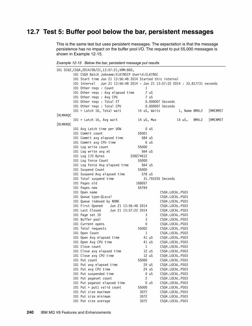
12.7 Test 5: Buffer pool below the bar, persistent messages
This is the same test but uses persistent messages. The expectation is that the message persistence has no impact on the buffer pool I/O. The request to put 55,000 messages is shown in Example 12-15.
Example 12-15 Below the bar, persistent message put results
101 SC62,CSQ4,2014/06/21,13:57:21,VRM:800, 101 CSQ4 Batch Jobname:ELKINSCP Userid:ELKINSC 101 Start time Jun 21 13:56:48 2014 Started this interval 101 Interval Jun 21 13:56:48 2014 - Jun 21 13:57:22 2014 : 33.817731 seconds 101 Other reqs : Count 1 101 Other reqs : Avg elapsed time 7 uS 101 Other reqs : Avg CPU 7 uS 101 Other reqs : Total ET 0.000007 Seconds 101 Other reqs : Total CPU 0.000007 Seconds 101 > Latch 16, Total wait 14 uS, Waits 1, Name BMXL2 |RMCRMST |RLMARQC 101 > Latch 16, Avg wait 14 uS, Max 14 uS, BMXL2 |RMCRMST |RLMARQC 101 Avg Latch time per UOW 0 uS 101 Commit count 55001 101 Commit avg elapsed time 584 uS 101 Commit avg CPU time 6 uS 101 Log write count 55000 101 Log write avg et 564 uS 101 Log I/O Bytes 228274612 101 Log Force Count 55000 101 Log Force Avg elapsed time 564 uS 101 Suspend Count 55000 101 Suspend Avg elapsed time 578 uS 101 Total suspend time 31.791035 Seconds 101 Pages old 168057 101 Pages new 55764 101 Open name CSQ4.LOCAL.PS03 101 Queue type:QLocal CSQ4.LOCAL.PS03 101 Queue indexed by NONE CSQ4.LOCAL.PS03 101 First Opened Jun 21 13:56:48 2014 CSQ4.LOCAL.PS03 101 Last Closed Jun 21 13:57:22 2014 CSQ4.LOCAL.PS03 101 Page set ID 3 CSQ4.LOCAL.PS03 101 Buffer pool 3 CSQ4.LOCAL.PS03 101 Current opens 0 CSQ4.LOCAL.PS03 101 Total requests 55002 CSQ4.LOCAL.PS03 101 Open Count 1 CSQ4.LOCAL.PS03 101 Open Avg elapsed time 41 uS CSQ4.LOCAL.PS03 101 Open Avg CPU time 41 uS CSQ4.LOCAL.PS03 101 Close count 1 CSQ4.LOCAL.PS03 101 Close avg elapsed time 12 uS CSQ4.LOCAL.PS03 101 Close avg CPU time 12 uS CSQ4.LOCAL.PS03 101 Put count 55000 CSQ4.LOCAL.PS03 101 Put avg elapsed time 24 uS CSQ4.LOCAL.PS03 101 Put avg CPU time 24 uS CSQ4.LOCAL.PS03 101 Put suspended time 0 uS CSQ4.LOCAL.PS03 101 Put pageset count 2 CSQ4.LOCAL.PS03 101 Put pageset elapsed time 0 uS CSQ4.LOCAL.PS03 101 Put + put1 valid count 55000 CSQ4.LOCAL.PS03 101 Put size maximum 3072 CSQ4.LOCAL.PS03 101 Put size minimum 3072 CSQ4.LOCAL.PS03 101 Put size average 3072 CSQ4.LOCAL.PS03
240 IBM MQ V8 Features and Enhancements

101 Put num persistent 55000 CSQ4.LOCAL.PS03 101 Curdepth maximum 55000 CSQ4.LOCAL.PS03 101 Total Queue elapsed time 1.36124e+06 uS CSQ4.LOCAL.PS03 101 Total Queue CPU used 1.32619e+06 uS CSQ4.LOCAL.PS03 101 Grand total CPU time 1.68074e+06 uS 101 Grand Elapsed time 3.3491e+07 uS
The second part of the persistent-message below-the-bar test retrieved the messages from the queue. The results are shown in Example 12-16.
Example 12-16 Below the bar, persistent message get results
190 SC62,CSQ4,2014/06/21,14:03:15,VRM:800, 190 CSQ4 Batch Jobname:ELKINSCP Userid:ELKINSC 190 Start time Jun 21 14:02:53 2014 Started this interval 190 Interval Jun 21 14:02:53 2014 - Jun 21 14:03:16 2014 : 22.941450 seconds 190 Other reqs : Count 1 190 Other reqs : Avg elapsed time 7 uS 190 Other reqs : Avg CPU 7 uS 190 Other reqs : Total ET 0.000007 Seconds 190 Other reqs : Total CPU 0.000007 Seconds 190 Commit count 55001 190 Commit avg elapsed time 332 uS 190 Commit avg CPU time 6 uS 190 Log write count 55000 190 Log write avg et 313 uS 190 Log I/O Bytes 27885092 190 Log Force Count 55000 190 Log Force Avg elapsed time 313 uS 190 Suspend Count 55000 190 Suspend Avg elapsed time 326 uS 190 Total suspend time 17.934289 Seconds 190 Pages old 220763 190 Open name CSQ4.LOCAL.PS03 190 Queue type:QLocal CSQ4.LOCAL.PS03 190 Queue indexed by NONE CSQ4.LOCAL.PS03 190 First Opened Jun 21 14:02:53 2014 CSQ4.LOCAL.PS03 190 Last Closed Jun 21 14:03:16 2014 CSQ4.LOCAL.PS03 190 Page set ID 3 CSQ4.LOCAL.PS03 190 Buffer pool 3 CSQ4.LOCAL.PS03 190 Current opens 0 CSQ4.LOCAL.PS03 190 Total requests 55002 CSQ4.LOCAL.PS03 190 Open Count 1 CSQ4.LOCAL.PS03 190 Open Avg elapsed time 44 uS CSQ4.LOCAL.PS03 190 Open Avg CPU time 44 uS CSQ4.LOCAL.PS03 190 Close count 1 CSQ4.LOCAL.PS03 190 Close avg elapsed time 12 uS CSQ4.LOCAL.PS03 190 Close avg CPU time 12 uS CSQ4.LOCAL.PS03 190 Get count 55000 CSQ4.LOCAL.PS03 190 Get avg elapsed time 78 uS CSQ4.LOCAL.PS03 190 Get avg CPU time 25 uS CSQ4.LOCAL.PS03 190 Get suspended time 52 uS CSQ4.LOCAL.PS03 190 Get pageset total count 16179 CSQ4.LOCAL.PS03 190 Get pageset elapsed time 52 uS CSQ4.LOCAL.PS03 190 Get total empty pages 763 CSQ4.LOCAL.PS03 190 Get TOQ average 360945026 uS CSQ4.LOCAL.PS03 190 Get TOQ maximum 365318200 uS CSQ4.LOCAL.PS03 190 Get TOQ minimum 354441055 uS CSQ4.LOCAL.PS03 190 Get valid count 55000 CSQ4.LOCAL.PS03 190 Get size maximum 3072 bytes CSQ4.LOCAL.PS03
Chapter 12. Advantages of a buffer pool above the bar 241

190 Get size minimum 3072 bytes CSQ4.LOCAL.PS03 190 Get size average 3072 bytes CSQ4.LOCAL.PS03 190 Get Dest-Next 55000 CSQ4.LOCAL.PS03 190 Get persistent count 55000 CSQ4.LOCAL.PS03 190 Curdepth maximum 54999 CSQ4.LOCAL.PS03 190 Total Queue elapsed time 4.31281e+06 uS CSQ4.LOCAL.PS03 190 Total Queue CPU used 1.41196e+06 uS CSQ4.LOCAL.PS03 190 Grand total CPU time 1.75778e+06 uS 190 Grand Elapsed time 2.25779e+07 uS
12.8 Test 6: Buffer pool above the bar, persistent messages
This is the above-the-bar buffer pool version of the same test with persistent messages. The expectation is that message persistence will have no impact on the buffer pool I/O. The request to put 55,000 messages is shown in Example 12-17.
Example 12-17 Above the bar, persistent message put results
121 SC62,CSQ4,2014/06/25,11:59:09,VRM:800, 121 CSQ4 Batch Jobname:ELKINSCP Userid:ELKINSC 121 Start time Jun 25 11:58:36 2014 Started this interval 121 Interval Jun 25 11:58:36 2014 - Jun 25 11:59:10 2014 : 33.384136 seconds 121 Other reqs : Count 1 121 Other reqs : Avg elapsed time 7 uS 121 Other reqs : Avg CPU 7 uS 121 Other reqs : Total ET 0.000007 Seconds 121 Other reqs : Total CPU 0.000007 Seconds 121 > Latch 11, Total wait 205 uS, Waits 1, Name SSSCONN|DMCSEGAL 121 > Latch 11, Avg wait 205 uS, Max 205 uS, SSSCONN|DMCSEGAL 121 > Latch 16, Total wait 375 uS, Waits 1, Name BMXL2 |RMCRMST |RLMARQC 121 > Latch 16, Avg wait 375 uS, Max 375 uS, BMXL2 |RMCRMST |RLMARQC 121 > Latch 19, Total wait 11859 uS, Waits 1, Name BMXL3 |CFMTODO |SRH1_L19 121 > Latch 19, Avg wait 11859 uS, Max 11859 uS, BMXL3 |CFMTODO |SRH1_L19 121 Longest latch wait at 00000000255a86b0 11859 uS 121 Avg Latch time per UOW 0 uS 121 Commit count 55001 121 Commit avg elapsed time 577 uS 121 Commit avg CPU time 6 uS 121 Log write count 55000 121 Log write avg et 558 uS 121 Log I/O Bytes 228274612 121 Log Force Count 55000 121 Log Force Avg elapsed time 558 uS 121 Suspend Count 55000 121 Suspend Avg elapsed time 571 uS 121 Total suspend time 31.443009 Seconds 121 Pages old 168057 121 Pages new 55764 121 Open name CSQ4.LOCAL.PS21 121 Queue type:QLocal CSQ4.LOCAL.PS21 121 Queue indexed by NONE CSQ4.LOCAL.PS21 121 First Opened Jun 25 11:58:36 2014 CSQ4.LOCAL.PS21 121 Last Closed Jun 25 11:59:10 2014 CSQ4.LOCAL.PS21 121 Page set ID 21 CSQ4.LOCAL.PS21
242 IBM MQ V8 Features and Enhancements

121 Buffer pool 21 CSQ4.LOCAL.PS21 121 Current opens 0 CSQ4.LOCAL.PS21 121 Total requests 55002 CSQ4.LOCAL.PS21 121 Open Count 1 CSQ4.LOCAL.PS21 121 Open Avg elapsed time 36 uS CSQ4.LOCAL.PS21 121 Open Avg CPU time 36 uS CSQ4.LOCAL.PS21 121 Close count 1 CSQ4.LOCAL.PS21 121 Close avg elapsed time 12 uS CSQ4.LOCAL.PS21 121 Close avg CPU time 12 uS CSQ4.LOCAL.PS21 121 Put count 55000 CSQ4.LOCAL.PS21 121 Put avg elapsed time 23 uS CSQ4.LOCAL.PS21 121 Put avg CPU time 22 uS CSQ4.LOCAL.PS21 121 Put suspended time 0 uS CSQ4.LOCAL.PS21 121 Put + put1 valid count 55000 CSQ4.LOCAL.PS21 121 Put size maximum 3072 CSQ4.LOCAL.PS21 121 Put size minimum 3072 CSQ4.LOCAL.PS21 121 Put size average 3072 CSQ4.LOCAL.PS21 121 Put num persistent 55000 CSQ4.LOCAL.PS21 121 Curdepth maximum 55000 CSQ4.LOCAL.PS21 121 Total Queue elapsed time 1.28937e+06 uS CSQ4.LOCAL.PS21 121 Total Queue CPU used 1.24485e+06 uS CSQ4.LOCAL.PS21 121 Grand total CPU time 1.58683e+06 uS 121 Grand Elapsed time 3.30628e+07 uS
The second part of the persistent-message above-the-bar test retrieves the messages from the queue. The results are shown in Example 12-18.
Example 12-18 Above the bar, persistent message get results
136 SC62,CSQ4,2014/06/25,12:00:48,VRM:800, 136 CSQ4 Batch Jobname:ELKINSCP Userid:ELKINSC 136 Start time Jun 25 12:00:30 2014 Started this interval 136 Interval Jun 25 12:00:30 2014 - Jun 25 12:00:49 2014 : 18.984844 seconds 136 Other reqs : Count 1 136 Other reqs : Avg elapsed time 7 uS 136 Other reqs : Avg CPU 7 uS 136 Other reqs : Total ET 0.000007 Seconds 136 Other reqs : Total CPU 0.000007 Seconds 136 Commit count 55001 136 Commit avg elapsed time 316 uS 136 Commit avg CPU time 6 uS 136 Log write count 55000 136 Log write avg et 298 uS 136 Log I/O Bytes 27885000 136 Log Force Count 55000 136 Log Force Avg elapsed time 298 uS 136 Suspend Count 55000 136 Suspend Avg elapsed time 310 uS 136 Total suspend time 17.079485 Seconds 136 Pages old 220763 136 Open name CSQ4.LOCAL.PS21 136 Queue type:QLocal CSQ4.LOCAL.PS21 136 Queue indexed by NONE CSQ4.LOCAL.PS21 136 First Opened Jun 25 12:00:30 2014 CSQ4.LOCAL.PS21 136 Last Closed Jun 25 12:00:49 2014 CSQ4.LOCAL.PS21 136 Page set ID 21 CSQ4.LOCAL.PS21 136 Buffer pool 21 CSQ4.LOCAL.PS21 136 Current opens 0 CSQ4.LOCAL.PS21 136 Total requests 55002 CSQ4.LOCAL.PS21 136 Open Count 1 CSQ4.LOCAL.PS21
Chapter 12. Advantages of a buffer pool above the bar 243

136 Open Avg elapsed time 45 uS CSQ4.LOCAL.PS21 136 Open Avg CPU time 45 uS CSQ4.LOCAL.PS21 136 Close count 1 CSQ4.LOCAL.PS21 136 Close avg elapsed time 11 uS CSQ4.LOCAL.PS21 136 Close avg CPU time 11 uS CSQ4.LOCAL.PS21 136 Get count 55000 CSQ4.LOCAL.PS21 136 Get avg elapsed time 22 uS CSQ4.LOCAL.PS21 136 Get avg CPU time 22 uS CSQ4.LOCAL.PS21 136 Get total empty pages 763 CSQ4.LOCAL.PS21 136 Get TOQ average 106223472 uS CSQ4.LOCAL.PS21 136 Get TOQ maximum 113502329 uS CSQ4.LOCAL.PS21 136 Get TOQ minimum 99102670 uS CSQ4.LOCAL.PS21 136 Get valid count 55000 CSQ4.LOCAL.PS21 136 Get size maximum 3072 bytes CSQ4.LOCAL.PS21 136 Get size minimum 3072 bytes CSQ4.LOCAL.PS21 136 Get size average 3072 bytes CSQ4.LOCAL.PS21 136 Get Dest-Next 55000 CSQ4.LOCAL.PS21 136 Get persistent count 55000 CSQ4.LOCAL.PS21 136 Curdepth maximum 54999 CSQ4.LOCAL.PS21 136 Total Queue elapsed time 1.24989e+06 uS CSQ4.LOCAL.PS21 136 Total Queue CPU used 1.22217e+06 uS CSQ4.LOCAL.PS21 136 Grand total CPU time 1.55228e+06 uS 136 Grand Elapsed time 1.86441e+07 uS
12.9 Test 7: Buffer pool above the bar, persistent messages, fixed pages
In this test, the above-the-bar buffer pool was altered to fix the pages in memory. The that was command used and the output from the command are shown in Example 12-19. This test can help the queue manager avoid the overhead of fixing and unfixing the pages in memory that must be done when working with persistent messages.
Example 12-19 ALTER BUFFPOOL command and messages returned
Command:-csq4 alter buffpool(21) pageclas(fixed4kb)Messages:CSQP024I -CSQ4 Request initiated for buffer pool 21 CSQ9022I -CSQ4 CSQPALTB ' ALTER BUFFPOOL' NORMAL COMPLETIONCSQP062I -CSQ4 Buffer pool 21 PAGECLAS changed, 905 restart required to take effect CSQP053I -CSQ4 Request completed for buffer pool 21, 906 buffers not changed
The queue manager was restarted to pick up the changes.
The results of the 55,000 messages of the put process, using a page-fixed above-the-bar buffer pool, are shown in Example 12-20.
Example 12-20 Page fixed above-the-bar buffer pool put test
59 SC62,CSQ4,2014/06/26,06:28:23,VRM:800, 59 CSQ4 Batch Jobname:ELKINSCP Userid:ELKINSC 59 Start time Jun 26 06:27:52 2014 Started this interval 59 Interval Jun 26 06:27:52 2014 - Jun 26 06:28:24 2014 : 32.227785 seconds 59 Other reqs : Count 1 59 Other reqs : Avg elapsed time 7 uS
244 IBM MQ V8 Features and Enhancements

59 Other reqs : Avg CPU 7 uS 59 Other reqs : Total ET 0.000007 Seconds 59 Other reqs : Total CPU 0.000007 Seconds 59 Commit count 55001 59 Commit avg elapsed time 557 uS 59 Commit avg CPU time 6 uS 59 Log write count 55000 59 Log write avg et 538 uS 59 Log I/O Bytes 228274520 59 Log Force Count 55000 59 Log Force Avg elapsed time 538 uS 59 Suspend Count 55000 59 Suspend Avg elapsed time 551 uS 59 Total suspend time 30.317776 Seconds 59 Pages old 168057 59 Pages new 55764 59 Open name CSQ4.LOCAL.PS21 59 Queue type:QLocal CSQ4.LOCAL.PS21 59 Queue indexed by NONE CSQ4.LOCAL.PS21 59 First Opened Jun 26 06:27:52 2014 CSQ4.LOCAL.PS21 59 Last Closed Jun 26 06:28:24 2014 CSQ4.LOCAL.PS21 59 Page set ID 21 CSQ4.LOCAL.PS21 59 Buffer pool 21 CSQ4.LOCAL.PS21 59 Current opens 0 CSQ4.LOCAL.PS21 59 Total requests 55002 CSQ4.LOCAL.PS21 59 Open Count 1 CSQ4.LOCAL.PS21 59 Open Avg elapsed time 42 uS CSQ4.LOCAL.PS21 59 Open Avg CPU time 42 uS CSQ4.LOCAL.PS21 59 Close count 1 CSQ4.LOCAL.PS21 59 Close avg elapsed time 12 uS CSQ4.LOCAL.PS21 59 Close avg CPU time 12 uS CSQ4.LOCAL.PS21 59 Put count 55000 CSQ4.LOCAL.PS21 59 Put avg elapsed time 23 uS CSQ4.LOCAL.PS21 59 Put avg CPU time 22 uS CSQ4.LOCAL.PS21 59 Put + put1 valid count 55000 CSQ4.LOCAL.PS21 59 Put size maximum 3072 CSQ4.LOCAL.PS21 59 Put size minimum 3072 CSQ4.LOCAL.PS21 59 Put size average 3072 CSQ4.LOCAL.PS21 59 Put num persistent 55000 CSQ4.LOCAL.PS21 59 Curdepth maximum 55000 CSQ4.LOCAL.PS21 59 Total Queue elapsed time 1.27037e+06 uS CSQ4.LOCAL.PS21 59 Total Queue CPU used 1.23954e+06 uS CSQ4.LOCAL.PS21 59 Grand total CPU time 1.57869e+06 uS 59 Grand Elapsed time 3.19149e+07 uS
The second part of the test (persistent message, above-the-bar, page-fixed buffer pool) retrieved the messages from the queue. The results are shown in Example 12-21.
Example 12-21 Page fixed above-the-bar buffer pool get test
74 SC62,CSQ4,2014/06/26,06:29:55,VRM:800, 74 CSQ4 Batch Jobname:ELKINSCP Userid:ELKINSC 74 Start time Jun 26 06:29:37 2014 Started this interval 74 Interval Jun 26 06:29:37 2014 - Jun 26 06:29:56 2014 : 19.004762 seconds 74 Other reqs : Count 1 74 Other reqs : Avg elapsed time 7 uS 74 Other reqs : Avg CPU 7 uS 74 Other reqs : Total ET 0.000007 Seconds 74 Other reqs : Total CPU 0.000007 Seconds 74 > Latch 11, Total wait 312 uS, Waits 1, Name SSSCONN|DMCSEGAL
Chapter 12. Advantages of a buffer pool above the bar 245

74 > Latch 11, Avg wait 312 uS, Max 312 uS, SSSCONN|DMCSEGAL 74 > Latch 19, Total wait 17 uS, Waits 1, Name BMXL3 |CFMTODO |SRH1_L19 74 > Latch 19, Avg wait 17 uS, Max 17 uS, BMXL3 |CFMTODO |SRH1_L19 74 Avg Latch time per UOW 0 uS 74 Commit count 55001 74 Commit avg elapsed time 316 uS 74 Commit avg CPU time 5 uS 74 Log write count 55000 74 Log write avg et 298 uS 74 Log I/O Bytes 27885000 74 Log Force Count 55000 74 Log Force Avg elapsed time 298 uS 74 Suspend Count 55000 74 Suspend Avg elapsed time 310 uS 74 Total suspend time 17.095315 Seconds 74 Pages old 220763 74 Open name CSQ4.LOCAL.PS21 74 Queue type:QLocal CSQ4.LOCAL.PS21 74 Queue indexed by NONE CSQ4.LOCAL.PS21 74 First Opened Jun 26 06:29:37 2014 CSQ4.LOCAL.PS21 74 Last Closed Jun 26 06:29:56 2014 CSQ4.LOCAL.PS21 74 Page set ID 21 CSQ4.LOCAL.PS21 74 Buffer pool 21 CSQ4.LOCAL.PS21 74 Current opens 0 CSQ4.LOCAL.PS21 74 Total requests 55002 CSQ4.LOCAL.PS21 74 Open Count 1 CSQ4.LOCAL.PS21 74 Open Avg elapsed time 46 uS CSQ4.LOCAL.PS21 74 Open Avg CPU time 46 uS CSQ4.LOCAL.PS21 74 Close count 1 CSQ4.LOCAL.PS21 74 Close avg elapsed time 11 uS CSQ4.LOCAL.PS21 74 Close avg CPU time 11 uS CSQ4.LOCAL.PS21 74 Get count 55000 CSQ4.LOCAL.PS21 74 Get avg elapsed time 22 uS CSQ4.LOCAL.PS21 74 Get avg CPU time 22 uS CSQ4.LOCAL.PS21 74 Get suspended time 0 uS CSQ4.LOCAL.PS21 74 Get total empty pages 763 CSQ4.LOCAL.PS21 74 Get TOQ average 98401608 uS CSQ4.LOCAL.PS21 74 Get TOQ maximum 105003124 uS CSQ4.LOCAL.PS21 74 Get TOQ minimum 91779666 uS CSQ4.LOCAL.PS21 74 Get valid count 55000 CSQ4.LOCAL.PS21 74 Get size maximum 3072 bytes CSQ4.LOCAL.PS21 74 Get size minimum 3072 bytes CSQ4.LOCAL.PS21 74 Get size average 3072 bytes CSQ4.LOCAL.PS21 74 Get Dest-Next 55000 CSQ4.LOCAL.PS21 74 Get persistent count 55000 CSQ4.LOCAL.PS21 74 Curdepth maximum 54999 CSQ4.LOCAL.PS21 74 Total Queue elapsed time 1.24569e+06 uS CSQ4.LOCAL.PS21 74 Total Queue CPU used 1.21813e+06 uS CSQ4.LOCAL.PS21 74 Grand total CPU time 1.54811e+06 uS 74 Grand Elapsed time 1.866e+07 uS
246 IBM MQ V8 Features and Enhancements

12.10 Test 8: Buffer pool below the bar, nonpersistent messages, I/O expected
This test gets information about the performance and cost for messages that are being put to and retrieved from a queue, using a buffer pool below the bar, and forced into page set I/O. The results from putting 30,000 messages are shown in Example 12-22.
Example 12-22 Below the bar with I/O put test, using buffer pool 4
29 SC62,CSQ4,2014/07/01,10:54:09,VRM:800, 29 CSQ4 Batch Jobname:ELKINSCP Userid:ELKINSC 29 Start time Jul 1 10:54:08 2014 Started this interval 29 Interval Jul 1 10:54:08 2014 - Jul 1 10:54:10 2014 : 1.629191 seconds 29 Other reqs : Count 1 29 Other reqs : Avg elapsed time 8 uS 29 Other reqs : Avg CPU 8 uS 29 Other reqs : Total ET 0.000008 Seconds 29 Other reqs : Total CPU 0.000008 Seconds 29 > Latch 16, Total wait 16585 uS, Waits 257, Name BMXL2 |RMCRMST |RLMARQC 29 > Latch 16, Avg wait 64 uS, Max 2204 uS, BMXL2 |RMCRMST |RLMARQC 29 Longest latch wait at 00000000255a86b0 16585 uS 29 Avg Latch time per UOW 0 uS 29 Commit count 30001 29 Commit avg elapsed time 14 uS 29 Commit avg CPU time 4 uS 29 Suspend Count 29999 29 Suspend Avg elapsed time 9 uS 29 Total suspend time 0.288058 Seconds 29 Pages old 91667 29 Pages new 30417 29 Open name CSQ4.LOCAL.PS04 29 Queue type:QLocal CSQ4.LOCAL.PS04 29 Queue indexed by NONE CSQ4.LOCAL.PS04 29 First Opened Jul 1 10:54:08 2014 CSQ4.LOCAL.PS04 29 Last Closed Jul 1 10:54:10 2014 CSQ4.LOCAL.PS04 29 Page set ID 4 CSQ4.LOCAL.PS04 29 Buffer pool 4 CSQ4.LOCAL.PS04 29 Current opens 0 CSQ4.LOCAL.PS04 29 Total requests 30002 CSQ4.LOCAL.PS04 29 Open Count 1 CSQ4.LOCAL.PS04 29 Open Avg elapsed time 43 uS CSQ4.LOCAL.PS04 29 Open Avg CPU time 43 uS CSQ4.LOCAL.PS04 29 Close count 1 CSQ4.LOCAL.PS04 29 Close avg elapsed time 12 uS CSQ4.LOCAL.PS04 29 Close avg CPU time 12 uS CSQ4.LOCAL.PS04 29 Put count 30000 CSQ4.LOCAL.PS04 29 Put avg elapsed time 35 uS CSQ4.LOCAL.PS04 29 Put avg CPU time 16 uS CSQ4.LOCAL.PS04 29 Put suspended time 18 uS CSQ4.LOCAL.PS04 29 Put pageset count 176 CSQ4.LOCAL.PS04 29 Put pageset elapsed time 17 uS CSQ4.LOCAL.PS04 29 Put + put1 valid count 30000 CSQ4.LOCAL.PS04 29 Put size maximum 3072 CSQ4.LOCAL.PS04 29 Put size minimum 3072 CSQ4.LOCAL.PS04 29 Put size average 3072 CSQ4.LOCAL.PS04 29 Put num not peristent 30000 CSQ4.LOCAL.PS04 29 Curdepth maximum 30000 CSQ4.LOCAL.PS04
Chapter 12. Advantages of a buffer pool above the bar 247

29 Total Queue elapsed time 1.05018e+06 uS CSQ4.LOCAL.PS04 29 Total Queue CPU used 502027 uS CSQ4.LOCAL.PS04 29 Grand total CPU time 648658 uS 29 Grand Elapsed time 1.48214e+06 uS
During the put test, the message Buffer pool n is too small (Example 12-23) was on the JES log, and is expected behavior for this test.
Example 12-23 Buffer pool too small message
CSQP020E -CSQ4 CSQPRSTW Buffer pool 4 is too small
The results from the get process are shown in Example 12-24.
Example 12-24 Below the bar with I/O get test, using buffer pool 4
44 SC62,CSQ4,2014/07/01,10:55:29,VRM:800, 44 CSQ4 Batch Jobname:ELKINSCP Userid:ELKINSC 44 Start time Jul 1 10:54:26 2014 Started this interval 44 Interval Jul 1 10:54:26 2014 - Jul 1 10:55:30 2014 : 64.141545 seconds 44 Other reqs : Count 1 44 Other reqs : Avg elapsed time 7 uS 44 Other reqs : Avg CPU 7 uS 44 Other reqs : Total ET 0.000007 Seconds 44 Other reqs : Total CPU 0.000007 Seconds 44 Commit count 30002 44 Commit avg elapsed time 13 uS 44 Commit avg CPU time 5 uS 44 Suspend Count 29994 44 Suspend Avg elapsed time 8 uS 44 Total suspend time 0.249374 Seconds 44 Pages old 120416 44 Open name CSQ4.LOCAL.PS04 44 Queue type:QLocal CSQ4.LOCAL.PS04 44 Queue indexed by NONE CSQ4.LOCAL.PS04 44 First Opened Jul 1 10:54:26 2014 CSQ4.LOCAL.PS04 44 Last Closed Jul 1 10:55:30 2014 CSQ4.LOCAL.PS04 44 Page set ID 4 CSQ4.LOCAL.PS04 44 Buffer pool 4 CSQ4.LOCAL.PS04 44 Current opens 0 CSQ4.LOCAL.PS04 44 Total requests 30003 CSQ4.LOCAL.PS04 44 Open Count 1 CSQ4.LOCAL.PS04 44 Open Avg elapsed time 48 uS CSQ4.LOCAL.PS04 44 Open Avg CPU time 48 uS CSQ4.LOCAL.PS04 44 Close count 1 CSQ4.LOCAL.PS04 44 Close avg elapsed time 18 uS CSQ4.LOCAL.PS04 44 Close avg CPU time 18 uS CSQ4.LOCAL.PS04 44 Get count 30001 CSQ4.LOCAL.PS04 44 Get avg elapsed time 118 uS CSQ4.LOCAL.PS04 44 Get avg CPU time 23 uS CSQ4.LOCAL.PS04 44 Get suspended time 95 uS CSQ4.LOCAL.PS04 44 Get pageset total count 15266 CSQ4.LOCAL.PS04 44 Get pageset elapsed time 95 uS CSQ4.LOCAL.PS04 44 Get total empty pages 416 CSQ4.LOCAL.PS04 44 Get TOQ average 20071333 uS CSQ4.LOCAL.PS04 44 Get TOQ maximum 20965327 uS CSQ4.LOCAL.PS04 44 Get TOQ minimum 17920145 uS CSQ4.LOCAL.PS04 44 Get valid count 30000 CSQ4.LOCAL.PS04 44 Get size maximum 3072 bytes CSQ4.LOCAL.PS04 44 Get size minimum 3072 bytes CSQ4.LOCAL.PS04
248 IBM MQ V8 Features and Enhancements

44 Get size average 3072 bytes CSQ4.LOCAL.PS04 44 Get Dest-Next 30001 CSQ4.LOCAL.PS04 44 Get not persistent count 30000 CSQ4.LOCAL.PS04 44 Curdepth maximum 29999 CSQ4.LOCAL.PS04 44 Total Queue elapsed time 3.55665e+06 uS CSQ4.LOCAL.PS04 44 Total Queue CPU used 700852 uS CSQ4.LOCAL.PS04 44 Grand total CPU time 856378 uS 44 Grand Elapsed time 3.95721e+06 uS
12.11 Test 9: Buffer pool above the bar, nonpersistent messages, I/O expected
This test gets information about the performance and costs for messages that are being put to and retrieved from a queue, using a buffer pool above the bar, and forced into page set I/O. The results from putting 30,000 messages are shown in Example 12-25.
Example 12-25 Above the bar with I/O put test, using buffer pool 20
15 SC62,CSQ4,2014/07/01,11:12:53,VRM:800, 15 CSQ4 Batch Jobname:ELKINSCP Userid:ELKINSC 15 Start time Jul 1 11:12:52 2014 Started this interval 15 Interval Jul 1 11:12:52 2014 - Jul 1 11:12:54 2014 : 1.408523 seconds 15 Other reqs : Count 1 15 Other reqs : Avg elapsed time 8 uS 15 Other reqs : Avg CPU 8 uS 15 Other reqs : Total ET 0.000008 Seconds 15 Other reqs : Total CPU 0.000008 Seconds 15 > Latch 16, Total wait 44004 uS, Waits 402, Name BMXL2 |RMCRMST |RLMARQC 15 > Latch 16, Avg wait 109 uS, Max 3582 uS, BMXL2 |RMCRMST |RLMARQC 15 Longest latch wait at 00000000254a86b0 44004 uS 15 Avg Latch time per UOW 1 uS 15 Commit count 30001 15 Commit avg elapsed time 15 uS 15 Commit avg CPU time 4 uS 15 Suspend Count 29998 15 Suspend Avg elapsed time 10 uS 15 Total suspend time 0.304018 Seconds 15 Pages old 91667 15 Pages new 30417 15 Open name CSQ4.LOCAL.PS20 15 Queue type:QLocal CSQ4.LOCAL.PS20 15 Queue indexed by NONE CSQ4.LOCAL.PS20 15 First Opened Jul 1 11:12:52 2014 CSQ4.LOCAL.PS20 15 Last Closed Jul 1 11:12:54 2014 CSQ4.LOCAL.PS20 15 Page set ID 20 CSQ4.LOCAL.PS20 15 Buffer pool 20 CSQ4.LOCAL.PS20 15 Current opens 0 CSQ4.LOCAL.PS20 15 Total requests 30002 CSQ4.LOCAL.PS20 15 Open Count 1 CSQ4.LOCAL.PS20 15 Open Avg elapsed time 42 uS CSQ4.LOCAL.PS20 15 Open Avg CPU time 42 uS CSQ4.LOCAL.PS20 15 Close count 1 CSQ4.LOCAL.PS20 15 Close avg elapsed time 12 uS CSQ4.LOCAL.PS20 15 Close avg CPU time 12 uS CSQ4.LOCAL.PS20 15 Put count 30000 CSQ4.LOCAL.PS20
Chapter 12. Advantages of a buffer pool above the bar 249

15 Put avg elapsed time 26 uS CSQ4.LOCAL.PS20 15 Put avg CPU time 16 uS CSQ4.LOCAL.PS20 15 Put suspended time 9 uS CSQ4.LOCAL.PS20 15 Put pageset count 1 CSQ4.LOCAL.PS20 15 Put pageset elapsed time 8 uS CSQ4.LOCAL.PS20 15 Put + put1 valid count 30000 CSQ4.LOCAL.PS20 15 Put size maximum 3072 CSQ4.LOCAL.PS20 15 Put size minimum 3072 CSQ4.LOCAL.PS20 15 Put size average 3072 CSQ4.LOCAL.PS20 15 Put num not peristent 30000 CSQ4.LOCAL.PS20 15 Curdepth maximum 30000 CSQ4.LOCAL.PS20 15 Total Queue elapsed time 808300 uS CSQ4.LOCAL.PS20 15 Total Queue CPU used 507930 uS CSQ4.LOCAL.PS20 15 Grand total CPU time 656775 uS 15 Grand Elapsed time 1.25997e+06 uS
The results from the get process are shown in Example 12-26.
Example 12-26 Above the bar with I/O get test, using buffer pool 20
44 SC62,CSQ4,2014/07/01,11:14:41,VRM:800, 44 CSQ4 Batch Jobname:ELKINSCP Userid:ELKINSC 44 Start time Jul 1 11:13:38 2014 Started this interval 44 Interval Jul 1 11:13:38 2014 - Jul 1 11:14:42 2014 : 63.927470 seconds 44 Other reqs : Count 1 44 Other reqs : Avg elapsed time 7 uS 44 Other reqs : Avg CPU 7 uS 44 Other reqs : Total ET 0.000007 Seconds 44 Other reqs : Total CPU 0.000007 Seconds 44 Commit count 30002 44 Commit avg elapsed time 13 uS 44 Commit avg CPU time 5 uS 44 Suspend Count 29994 44 Suspend Avg elapsed time 8 uS 44 Total suspend time 0.257436 Seconds 44 Pages old 120416 44 Open name CSQ4.LOCAL.PS20 44 Queue type:QLocal CSQ4.LOCAL.PS20 44 Queue indexed by NONE CSQ4.LOCAL.PS20 44 First Opened Jul 1 11:13:38 2014 CSQ4.LOCAL.PS20 44 Last Closed Jul 1 11:14:42 2014 CSQ4.LOCAL.PS20 44 Page set ID 20 CSQ4.LOCAL.PS20 44 Buffer pool 20 CSQ4.LOCAL.PS20 44 Current opens 0 CSQ4.LOCAL.PS20 44 Total requests 30003 CSQ4.LOCAL.PS20 44 Open Count 1 CSQ4.LOCAL.PS20 44 Open Avg elapsed time 45 uS CSQ4.LOCAL.PS20 44 Open Avg CPU time 45 uS CSQ4.LOCAL.PS20 44 Close count 1 CSQ4.LOCAL.PS20 44 Close avg elapsed time 19 uS CSQ4.LOCAL.PS20 44 Close avg CPU time 19 uS CSQ4.LOCAL.PS20 44 Get count 30001 CSQ4.LOCAL.PS20 44 Get avg elapsed time 111 uS CSQ4.LOCAL.PS20 44 Get avg CPU time 24 uS CSQ4.LOCAL.PS20 44 Get suspended time 86 uS CSQ4.LOCAL.PS20 44 Get pageset total count 14343 CSQ4.LOCAL.PS20 44 Get pageset elapsed time 86 uS CSQ4.LOCAL.PS20 44 Get total empty pages 416 CSQ4.LOCAL.PS20 44 Get TOQ average 47403374 uS CSQ4.LOCAL.PS20 44 Get TOQ maximum 48197278 uS CSQ4.LOCAL.PS20
250 IBM MQ V8 Features and Enhancements

44 Get TOQ minimum 45397087 uS CSQ4.LOCAL.PS20 44 Get valid count 30000 CSQ4.LOCAL.PS20 44 Get size maximum 3072 bytes CSQ4.LOCAL.PS20 44 Get size minimum 3072 bytes CSQ4.LOCAL.PS20 44 Get size average 3072 bytes CSQ4.LOCAL.PS20 44 Get Dest-Next 30001 CSQ4.LOCAL.PS20 44 Get not persistent count 30000 CSQ4.LOCAL.PS20 44 Curdepth maximum 29999 CSQ4.LOCAL.PS20 44 Total Queue elapsed time 3.33586e+06 uS CSQ4.LOCAL.PS20 44 Total Queue CPU used 742701 uS CSQ4.LOCAL.PS20 44 Grand total CPU time 900897 uS 44 Grand Elapsed time 3.74621e+06 uS
12.12 Test comparisons
In this section, comparisons between the simple tests are listed in a table to help you more quickly see how the tests compare.
12.12.1 No I/O for either buffer pool comparison
Table 12-1 summarizes the nonpersistent tests where there was no I/O to the page sets for either below- or above-the-bar buffer pools. All values are in microseconds. The results show very little difference in either CPU or elapsed time; the above-the-bar gets are slightly more expensive, and the below-the-bar puts cost a fraction more.
Table 12-1 Comparison between buffer pools below and above the bar, no page set I/O
Action or value Below-bar put Below-bar get Above-bar put Above-bar get
MQOPEN 40 43 37 46
MQCLOSE 11 10 11 11
Average CPU for put or get
16 18 16 18
Average elapsed time for put or get
17 18 16 18
Get pageset I/O count 0 0
Total CPU 434563 459664 422286 460564
Total elapsed time 654343 622053 597192 622884
CPU difference (BB-AB)
12277 -900
Elapsed time differences (BB-AA)
57151 -831
Chapter 12. Advantages of a buffer pool above the bar 251

12.12.2 Nonpersistent message, below-the-bar I/O comparison
Table 12-2 summarizes the nonpersistent tests where the below-the-bar buffer pool had I/O to the page set and the above-the-bar buffer pool did not. All values are in microseconds. The differences reported in this simple test clearly show the savings that I/O avoidance can produce. This is particularly noticeable in the MQGET elapsed time. For an application where throughput is a key factor, this difference can mean that service-level agreements (SLAs) are met (or not).
Table 12-2 Comparison between below-the-bar and above-the-bar nonpersistent messages
12.12.3 Persistent message, below-the-bar I/O comparison
Table 12-3 on page 253 shows that the same tests were run as the previous test except that the messages are now persistent. All values are in microseconds. The results are expected. Be aware that the persistent message test had more opportunity for variation when repeated because of these reasons:
� Log file switching� Log file co-located with one or more page sets in use
Typically, these factors are more dramatically evident in the elapsed time differences.
Action or value Below-bar put Below-bar get Above-bar put Above-bar get
MQOPEN 40 43 41 45
MQCLOSE 11 11 11 11
Average CPU for put or get
16 20 16 18
Average elapsed timefor put or get
17 63 16 18
Get pageset I/O count 13,318 0
Total CPU in microseconds
1,190,450 1,397,110 1,158,480 1,270,110
Total elapsed timein microseconds
1,762,830 4,188,260 1,630,350 1,723,470
CPU difference (BB-AB)
31,970 127,000
Elapsed time differences (BB-AA)
132,480 2,464,790
252 IBM MQ V8 Features and Enhancements

Table 12-3 Comparison between below-the-bar and above-the-bar persistent messages
12.12.4 Persistent message using fixed pages comparison
Table 12-4 summarizes the persistent tests. All values are in microseconds. The persistent message using fixed (or pinned) pages test shows similar results to the non-fixed pages because no paging took place in the environment.
Table 12-4 Comparison between below the bar and above the bar with fixed pages persistent
Action or value Below-bar put Below-bar get Above-bar put Above-bar get
MQOPEN 41 44 36 45
MQCLOSE 12 12 12 11
Average CPU for put or get
24 25 22 22
Average elapsed timefor put or get
24 78 23 22
Get pageset I/O count 13,318 0
Total CPU in microseconds
1,680,740 1,757,780 1,586,830 1548110
Total Elapsed time in microseconds
33,491,000 22,577,900 33,066,280 18,644,100
CPU difference (BB-AB)
93,910 205,500
Elapsed time differences(BB-AA)
424,720 3,933,800
Action or value Below-bar put Below-bar get Above-bar put Above-bar get
MQOPEN 41 44 42 46
MQCLOSE 12 12 12 11
Average CPU for put or get
24 25 22 22
Average elapsed time for put or get
24 78 23 22
Get pageset I/O count 13,318
Total CPU in microseconds
1,680,740 1,757,780 1,578,690 1,548,110
Total elapsed time in microseconds
33,491,000 22,577,900 31,914,900 18,660,000
CPU difference (BB-AB)
102,050 209,670
Elapsed time differences (BB-AA)
1,576,100 3,917,900
Chapter 12. Advantages of a buffer pool above the bar 253

12.12.5 Nonpersistent message, I/O below- and above-the-bar I/O comparison
Table 12-5 summarizes above and below the bar with page set I/O tests. All values are in microseconds. In the tests where I/O was done for both below and above the bar, additional CPU was used for the above-the-bar test on both the puts and the gets. The above-the-bar puts cost approximately .25 of a microsecond more per put; the gets cost about 1.48 microseconds more. An interesting result is that the elapsed time was lower, but at an insignificant difference.
Table 12-5 Comparison between below the bar and above the bar with I/O to page sets
12.13 Summary
These tests are not intended to be a performance report, but to provide a testing method and give some preliminary numbers from an untuned system. This pattern of tests, when run in your environment, can give good information about the CPU and elapsed time changes, and benefits that your queue managers and applications might experience when queues are moved to buffer pools above the bar.
Action or value Below-bar put Below-bar get Above-bar put Above-bar get
MQOPEN 43 48 42 45
MQCLOSE 12 18 12 19
Average CPU for put or get
16 23 12 19
Average elapsed time for put or get
35 118 26 111
Get pageset I/O count
Total CPUin microseconds
648658 856378 656775 900897
Total elapsed timein microseconds
1,482,140 3,957,210 1,259,970 3,746,210
CPU difference(BB-AB)
-8117 -44519
Elapsed time differences(BB-AA)
1851 2123
254 IBM MQ V8 Features and Enhancements

Chapter 13. SCM scenarios
This chapter describes two scenarios. They provide an in-depth examination of two storage class memory (SCM) use cases that are discussed in Chapter 8, “Using new System z features” on page 125.
Each scenario offers some analysis of the performance characteristics of using SCM with IBM MQ application structures.
This chapter contains the following topics:
� 13.1, “SCM scenario 1: Emergency storage” on page 256� 13.2, “SCM scenario 2: Improved performance” on page 276
13
Note: Do not use the information in this chapter as performance data because testing was not done in a benchmark environment. Instead the information is intended to act as a methodology for how you can measure performance of SCM with IBM MQ in your environment.
© Copyright IBM Corp. 2014. All rights reserved. 255

13.1 SCM scenario 1: Emergency storage
This section describes how to set up a scenario based on the emergency storage use case introduced in 8.3, “Use cases for SCM with MQ application structures” on page 133.
For this scenario, we used a queue sharing group, IBM1, that contains a single queue manager, CSQ3. In addition to the administration structure, the queue sharing group defined a single application structure, SCEN1. The application structure was used by a single shared queue, SCEN1.Q. The SCEN1 application structure was stored in coupling facility (CF) CF01 as the IBM1SCEN1 structure, which had a maximum size of 1 GB. This configuration is illustrated in Figure 13-1.
For this scenario, we describe the addition of shared message data sets (SMDS), and then of SCM to the structure. We also describe simple tests that illustrate how the capacity and performance characteristics of the structure change.
Figure 13-1 Basic configuration for scenario 1
13.1.1 Basic configuration for scenario 1
To set up the configuration, shown in Figure 13-1, we assume that queue manager CSQ3 is already the only member of queue sharing group IBM1.
Creating structure IBM1SCEN1The definition for structure IBM1SCEN1 was added to the coupling facility resource manager (CFRM) policy. For simplicity, the structure was defined so that it could be created in only a single coupling facility, CF01, by specifying PREFLIST(CF01).
High availability: To allow for high availability, we suggest including at least two CFs in the PREFLIST for any structures that are used by IBM MQ.
256 IBM MQ V8 Features and Enhancements

Example 13-1 shows that the CFRM policy was then refreshed by running the following system command:
SETXCF START,POLICY,TYPE=CFRM,POLNAME=polname
Example 13-1 Sample CFRM policy for structure IBM1SCEN1
STRUCTURE NAME(IBM1SCEN1)SIZE(1024M)INITSIZE(512M)ALLOWAUTOALT(YES) FULLTHRESHOLD(85) PREFLIST(CF01)ALLOWREALLOCATE(YES) DUPLEX(DISABLED) ENFORCEORDER(NO)
Next, we verified that the structure was created correctly by using the following command:
D XCF,STR,STRNAME=IBM1SCEN1
The output is shown in Figure 13-2. At this point the structure is not allocated because it is not yet defined to the queue sharing group.
Figure 13-2 Response to D XCF,STR,STRNAME=IBM1SCEN1 command
Creating MQ definitionsAfter the structure is defined in the CFRM policy, MQ must be configured to make use of it. This is done by creating an MQ CFSTRUCT object by using the DEFINE CFSTRUCT command. The settings we use are shown in Example 13-2 on page 258.
Initially we want to understand how many messages can fit entirely in the structure, so offloading is disabled by setting all the OFFLDiSZ parameters to 64K. For simplicity, the application structure was configured so that any messages over 63 KB are offloaded to DB2. Because we will not use messages of this size, we do not need to configure SMDS.
RESPONSE=SC61 IXC360I 04.27.52 DISPLAY XCF 638 STRNAME: IBM1SCEN1 STATUS: NOT ALLOCATED POLICY INFORMATION: POLICY SIZE : 1024 M POLICY INITSIZE: 512 M POLICY MINSIZE : 384 M FULLTHRESHOLD : 85 ALLOWAUTOALT : YES REBUILD PERCENT: N/A DUPLEX : DISABLED ALLOWREALLOCATE: YES PREFERENCE LIST: CF01 ENFORCEORDER : NO EXCLUSION LIST IS EMPTY EVENT MANAGEMENT: MESSAGE-BASED MANAGER SYSTEM NAME: SC53 MANAGEMENT LEVEL : 01050107
Chapter 13. SCM scenarios 257

Example 13-2 Defining application structure SCEN1
DEFINE CFSTRUCT(SCEN1) CFCONLOS(TOLERATE) CFLEVEL(5) DESCR('Structure for SCM scenario 1') RECOVER(NO) RECAUTO(YES) OFFLOAD(DB2) OFFLD1SZ(64K) OFFLD1TH(70) OFFLD2SZ(64K) OFFLD2TH(80) OFFLD3SZ(64K) OFFLD3TH(90)
We then validate the application structure with the DISPLAY CFSTRUCT(SCEN1) MQ command. The output from this command is shown in Figure 13-3.
Figure 13-3 Output of DISPLAY CFSTRUCT(SCEN1) command
The SCEN1.Q shared queue is then defined to use SCEN1 with the following MQSC command:
DEFINE QLOCAL(SCEN1.Q) QSGDISP(SHARED) CFSTRUCT(SCEN1) MAXDEPTH(999999999)
Checking the configurationAlthough a shared queue is now defined to use the IBM1SCEN1 structure, the queue manager will not connect to the structure until it is first used. Until this happens, the structure remains in a NOT ALLOCATED state, as shown in Figure 13-2 on page 257.
To force the queue manager to connect to the structure, we use MQ Explorer to put a single message to queue SCEN1.Q, and then take it off again. We then issue the following command:
D XCF,STR,STRNAME=IBM1SCEN1
The results of this system command are shown in Figure 13-4 on page 259. It shows that the structure is allocated as a list structure, and is connected from the CSQ3MSTR address
04.58.26 STC18931 CSQM201I -CSQ3 CSQMDRTC DISPLAY CFSTRUCT DETAILS 164 164 CFSTRUCT(SCEN1) 164 DESCR(Structure for SCM scenario 1) 164 CFLEVEL(5) 164 RECOVER(NO) 164 OFFLOAD(DB2) 164 OFFLD1TH(70) 164 OFFLD1SZ(64K) 164 OFFLD2TH(80) 164 OFFLD2SZ(64K) 164 OFFLD3TH(90) 164 OFFLD3SZ(64K) 164 DSGROUP() 164 DSBLOCK(256K) 164 DSBUFS(100) 164 DSEXPAND(YES) 164 RECAUTO(YES) 164 CFCONLOS(TOLERATE) 164 ALTDATE(2014-06-17) 164 ALTTIME(04.52.22) 164 END CFSTRUCT DETAILS
258 IBM MQ V8 Features and Enhancements

space. The SPACE USAGE section shows that the default MQ ratio of one entry to six elements is being used (1,419,176 elements divided by 236,751 entries is under six). This will change when we start using the structure.
Figure 13-4 Structure IBM1SCEN1 is now allocated
IXC360I 06.24.05 DISPLAY XCF 288 STRNAME: IBM1SCEN1 STATUS: ALLOCATED EVENT MANAGEMENT: MESSAGE-BASED TYPE: SERIALIZED LIST POLICY INFORMATION: POLICY SIZE : 1024 M POLICY INITSIZE: 512 M POLICY MINSIZE : 384 M FULLTHRESHOLD : 85 ALLOWAUTOALT : YES REBUILD PERCENT: N/A DUPLEX : DISABLED ALLOWREALLOCATE: YES PREFERENCE LIST: CF01 ENFORCEORDER : NO EXCLUSION LIST IS EMPTY ACTIVE STRUCTURE ---------------- ALLOCATION TIME: 06/17/2014 06:19:32 CFNAME : CF01 COUPLING FACILITY: 002827.IBM.02.00000000B8D7 PARTITION: 3B CPCID: 00 STORAGE CONFIGURATION ALLOCATED MAXIMUM % ACTUAL SIZE: 512 M 1024 M 50 SPACE USAGE IN-USE TOTAL % ENTRIES: 33 236751 0 ELEMENTS: 48 1419176 0 EMCS: 2 189168 0 LOCKS: 1024 ACTUAL SUBNOTIFYDELAY: 5000 PHYSICAL VERSION: CD515C50 CE2ED258 LOGICAL VERSION: CD515C50 CE2ED258 SYSTEM-MANAGED PROCESS LEVEL: 9 XCF GRPNAME : IXCLO053 DISPOSITION : KEEP ACCESS TIME : NOLIMIT MAX CONNECTIONS: 32 # CONNECTIONS : 1 CONNECTION NAME ID VERSION SYSNAME JOBNAME ASID STATE ---------------- -- -------- -------- -------- ---- ---------------- CSQEIBM1CSQ301 01 00010059 SC61 CSQ3MSTR 0091 ACTIVE
Chapter 13. SCM scenarios 259

13.1.2 Testing the basic configuration with scenario 1
To get an idea of the baseline performance of our configuration, we use a single threaded JMS application (putting application) that repeatedly puts a nonpersistent BytesMessage, containing 30 KB of data, to the SCEN1.Q queue. The messages were put out of sync point. When the application fills up the structure and has an exception that contains the MQRC_STORAGE_MEDIUM _FULL return code, it stops.
On the first test run, the structure rapidly used the 512 MB that was originally allocated to it. The JMS application was putting messages so fast that not enough time was available for the CF to automatically increase the structure size, so the application received the MQRC_STORAGE_MEDIUM _FULL return code and stopped.
To prevent this happening again the structure was increased to its maximum size of 1 GB by issuing the following system command:
SETXCF START,ALTER,STRNAME=IBM1SCEN1,SIZE=1024M
The queue was then cleared and the test was run again several times. Each time, more messages were put on the queue. Output from the D XCF,STR,STRNAME=IBM1SCEN1 command showed that the ratio of entries to elements was gradually changing to a value that was optimal for messages of the size being used in the test.
The last couple of runs achieved a maximum queue depth of 27,864 messages. With this number of messages, the space usage section of the D XCF,STR,STRNAME=IBM1SCEN1 output indicated the information shown in Figure 13-5.
Figure 13-5 Space usage for IBM1SCEN1 structure when full with 27,864 messages
The total entry-to-element ratio changed from the default of 1:6 to a value of approximately 1:101. This ratio is close to the 1:123 ratio that is required for a JMS BytesMessage of size 30 KB.
We now understand why the structure is full. Adding another message requires one more entry, of which there are plenty, and 123 elements. However only 91 elements are available.
Figure 13-6 on page 261 shows how the depth of SCEN1.Q increased over time when running the putting application. Just over three seconds is the amount of time to fill the queue with messages.
SPACE USAGE IN-USE TOTAL % ENTRIES: 27897 33821 82 ELEMENTS: 3427320 3427411 99 EMCS: 2 386218 0 LOCKS: 1024
260 IBM MQ V8 Features and Enhancements

Figure 13-6 Depth of SCEN1.Q over time when using the basic configuration
Although this chart implies that messages enter the queue at a constant rate, this is not the case. If we draw a chart showing the variation in the number of milliseconds (ms) required for 1000 messages to be put to the queue (Figure 13-7), you see that putting 1000 messages when the test first starts, takes much longer than when the test ends. This behavior is expected because time is necessary for both the JVM that is running the test, and the queue manager, to warm up. Toward the end of the test, messages are being put to the queue at approximately 1000 messages every 85 ms.
Figure 13-7 Variation in time for putting 1000 messages on SCEN1.Q when using the basic configuration
Chapter 13. SCM scenarios 261

Measurements were also taken of the time spent to empty SCEN1.Q using a single threaded JMS application (getting application) that destructively got messages out of sync point until the queue was empty. Slightly more time was spent getting messages from the queue than putting them. The getting application took 3.97 seconds to empty the queue. The average get rate was about 1000 messages in 104 ms.
13.1.3 Adding SMDS to scenario 1
For our next tests, the basic configuration (described in 13.1.1, “Basic configuration for scenario 1” on page 256) was adjusted so that the SMDS was used for offloading messages according to the default offload rules. This configuration is shown in Figure 13-8.
Figure 13-8 Adding SMDS to application structure SCEN1
262 IBM MQ V8 Features and Enhancements

Creating the SMDS data setThe SMDS data set that the SCEN1 application structure uses was created by editing the CSQ4SMDS sample JCL, as shown in Example 13-3.
Example 13-3 JCL for creating SMDS for application structure SCEN1
//CSQ4SMDS JOB NOTIFY=&SYSUID//* //* Allocate SMDS //* //DEFINE EXEC PGM=IDCAMS,REGION=4M //SYSPRINT DD SYSOUT=* //SYSIN DD *
DEFINE CLUSTER - (NAME(CSQSMDS.SCEN1.CSQ3.SMDS) - MEGABYTES(5000 3000) - LINEAR - SHAREOPTIONS(2 3) ) - DATA - (NAME(CSQSMDS.SCEN1.CSQ3.SMDS.DATA) ) /* //* //* Format the SMDS //* //FORM EXEC PGM=CSQJUFMT,COND=(0,NE),REGION=0M//STEPLIB DD DSN=MQ800.SCSQANLE,DISP=SHR // DD DSN=MQ800.SCSQAUTH,DISP=SHR //SYSUT1 DD DISP=OLD,DSN=CSQSMDS.SCEN1.CSQ3.SMDS //SYSPRINT DD SYSOUT=*
Changing the MQ configuration The SCEN1 application structure was then altered to use SMDS for offloading, and the default offload rules were implemented. The following MQSC command was used:
ALTER CFSTRUCT(SCEN1) OFFLOAD(SMDS) OFFLD1SZ(32K) OFFLD2SZ(4K) OFFLD3SZ(0K) DSGROUP('CSQSMDS.SCEN1.*.SMDS') DSBLOCK(1M)
Because SCEN1.Q is the only shared queue on the SCEN1 application structure, the DSBLOCK value was set to 1M, the largest value possible. This should be the most efficient setting for our scenario.
Because the messages sent by the putting application are 30 KB, offloading to SMDS will not start until the second offload rule is met, when the structure is 80% full.
13.1.4 Testing SMDS with scenario 1
After SMDS was configured we reran our putting application. As before, several runs were needed to allow for rebalancing of the entry-to-element ratio. The ratio changed because, although the same message size was being used as in the previous runs, messages that are offloaded have a pointer to the offloaded message stored in the structure. This pointer is stored in the form of one entry and two elements. This means that there are two phases of the test, characterized by different entry-to-element ratios:
� Phase one: Messages are stored entirely in the structure; ratio of 1:123 is used.� Phase two: Messages are stored in SMDS and message pointers stored in the structure;
ratio of 1:2 is used.
Chapter 13. SCM scenarios 263
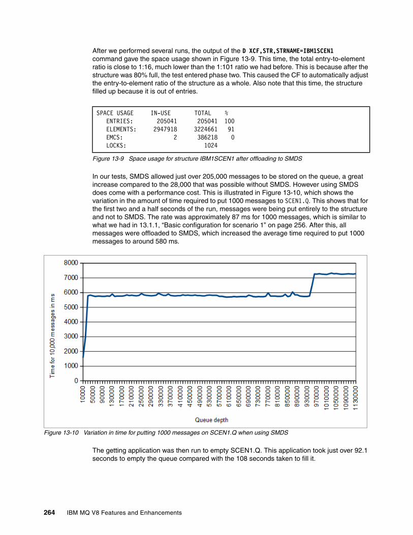
After we performed several runs, the output of the D XCF,STR,STRNAME=IBM1SCEN1 command gave the space usage shown in Figure 13-9. This time, the total entry-to-element ratio is close to 1:16, much lower than the 1:101 ratio we had before. This is because after the structure was 80% full, the test entered phase two. This caused the CF to automatically adjust the entry-to-element ratio of the structure as a whole. Also note that this time, the structure filled up because it is out of entries.
Figure 13-9 Space usage for structure IBM1SCEN1 after offloading to SMDS
In our tests, SMDS allowed just over 205,000 messages to be stored on the queue, a great increase compared to the 28,000 that was possible without SMDS. However using SMDS does come with a performance cost. This is illustrated in Figure 13-10, which shows the variation in the amount of time required to put 1000 messages to SCEN1.Q. This shows that for the first two and a half seconds of the run, messages were being put entirely to the structure and not to SMDS. The rate was approximately 87 ms for 1000 messages, which is similar to what we had in 13.1.1, “Basic configuration for scenario 1” on page 256. After this, all messages were offloaded to SMDS, which increased the average time required to put 1000 messages to around 580 ms.
Figure 13-10 Variation in time for putting 1000 messages on SCEN1.Q when using SMDS
The getting application was then run to empty SCEN1.Q. This application took just over 92.1 seconds to empty the queue compared with the 108 seconds taken to fill it.
SPACE USAGE IN-USE TOTAL % ENTRIES: 205041 205041 100 ELEMENTS: 2947918 3224661 91 EMCS: 2 386218 0 LOCKS: 1024
264 IBM MQ V8 Features and Enhancements

Figure 13-11 shows the variation in the amount of time required to get 1000 messages from the queue. The first set of “got” messages will not have been offloaded to SMDS and so the entire message will be in the structure. These messages can be “got” quickly, so the amount of time required to get them is over 100 ms for 1000 messages. The messages that have been offloaded to SMDS take much longer to get because of disk I/O. These messages take approximately 470 ms for 1000 messages.
The last section of the graph shows that the last 24,000 messages take even longer to get. Around 560 ms for 1000 messages. This might be because of I/O contention, or possibly because of slower DASD being used by that SMDS extent.
Figure 13-11 Variation in time for getting 1000 messages from SCEN1.Q when using SMDS
Chapter 13. SCM scenarios 265

13.1.5 Adding SCM to scenario 1
This section describes the process of adding 4 GB of SCM to structure IBM1SCEN1. This results in the configuration shown in Figure 13-12.
Figure 13-12 Adding SCM to scenario 1
The zEC12 that was used for the scenarios described in this book already has SCM installed and 16 GB allocated to CF01. The D CF,CFNAME=CF01 system command was used to confirm this. The output from the command is shown in Figure 13-13 on page 267. SCM usage is shown under the STORAGE CONFIGURATION section at the bottom.
266 IBM MQ V8 Features and Enhancements

Figure 13-13 SCM usage confirmed in output from D CF,CFNAME=CF01 command
For our tests, we added 4 GB of SCM to structure IBM1SCEN1. This was done by updating the CFRM policy with the SCMMAXSIZE and SCMALGORITHM keywords as indicated in Example 13-4.
Example 13-4 Updating the CFRM policy for structure IBM1SCEN1 with SCM
STRUCTURE NAME(IBM1SCEN1)SIZE(1024M)INITSIZE(512M)ALLOWAUTOALT(YES) FULLTHRESHOLD(85) PREFLIST(CF01)ALLOWREALLOCATE(YES) DUPLEX(DISABLED) ENFORCEORDER(NO)SCMMAXSIZE(4G)SCMALGORITHM(KEYPRIORITY1)
RESPONSE=SC61 IXL150I 06.20.38 DISPLAY CF 243 COUPLING FACILITY 002827.IBM.02.00000000B8D7 PARTITION: 3B CPCID: 00 LP NAME: A3B CPC NAME: SCZP401 CONTROL UNIT ID: FFD4 NAMED CF01 COUPLING FACILITY SPACE UTILIZATION ALLOCATED SPACE DUMP SPACE UTILIZATION STRUCTURES: 776 M STRUCTURE DUMP TABLES: 0 M DUMP SPACE: 2 M TABLE COUNT: 0 FREE SPACE: 6938 M FREE DUMP SPACE: 2 M TOTAL SPACE: 7716 M TOTAL DUMP SPACE: 2 M MAX REQUESTED DUMP SPACE: 0 M VOLATILE: YES CFLEVEL: 19 CFCC RELEASE 19.00, SERVICE LEVEL 02.13 BUILT ON 04/28/2014 AT 13:02:00 STORAGE INCREMENT SIZE: 1 M STORAGE-CLASS MEMORY INCREMENT SIZE: 1 M COUPLING FACILITY HAS 2 SHARED AND 0 DEDICATED PROCESSORS DYNAMIC CF DISPATCHING: OFF COUPLING FACILITY IS NOT STANDALONE COUPLING THIN INTERRUPTS: NOT-ENABLED CF REQUEST TIME ORDERING: REQUIRED AND ENABLED STORAGE CONFIGURATION ALLOCATED FREE TOTAL CONTROL SPACE: 778 M 6938 M 7716 M NON-CONTROL SPACE: 0 M 0 M 0 M STORAGE-CLASS MEMORY: 0 M 16384 M 16384 M
Chapter 13. SCM scenarios 267

The CFRM policy was then activated by issuing the following command:
SETXCF START,POLICY,TYPE=CFRM,POLNAME=polname
Because the IBM1SCEN1 structure was allocated when these changes were made, the following system command was used to rebuild the structure:
SETXCF START,REBUILD,STRNM=IBM1SCEN1
When this was done, the structure was already full with message data. Because of this, part of the rebuild involved pre-staging some of the messages from the structure into SCM. Figure 13-15 on page 269 shows the output of the D XCF,STR,STRNAME=IBM1SCEN1 system command. This indicates the following information:
� It provides confirmation that 4 GB of SCM was added to the structure.
� Because of pre-staging, 88 MB of SCM was used to store message data. There is now free space in the structure where there was none before SCM was added.
� A total of 3 MB of augmented space was used to track SCM usage. For this structure, the fixed augmented space was 3 MB. Presumably the amount of dynamic augmented space used in this example was minimal.
� The point at which the pre-staging algorithm starts to move data from the structure into SCM is when the structure is 90% full. This is indicated by the non-configurable SCMHIGHTHRESHOLD property.
� The point below which the pre-fetching algorithm starts to move data from SCM into the structure is when the structure is 70% full. This is indicated by the non-configurable SCMLOWTHRESHOLD property.
� The maximum entry-to-element ratio in SCM is the same as the total entry-to-element ratio in the structure. In both cases, the ratio is 1:14.35, to two decimal places. As mentioned in 8.2.3, “How SCM works with MQ” on page 130 the entry-to-element ratio used by SCM is fixed to the same ratio used by the structure when data is first copied into SCM from the structure. Figure 13-14 shows the structure before SCM was added. As expected, the in-use entry-to-element ratio is 205,041:2,947,918, which is one entry to 14.37 elements, close to 14.35.
� Figure 13-15 on page 269 illustrates that the pre-staging algorithm works on the message data that is least likely to next get from the queue (those MQ messages that were most recently put and, with the lowest priority, will be moved into SCM first). The application structure was configured to use SMDS, with the default offload rules, and filled up before adding SCM. As a result, the last messages added to the structure would have been offloaded to SMDS. Messages that are offloaded to SMDS have a message pointer stored in the structure that consists of one entry and two elements. The allocated entry-to-element ratio in SCM is 120,120:240,240 which is exactly one entry to two elements, proving that they are SMDS message pointers.
Figure 13-14 Space usage for structure IBM1SCEN1 prior to rebuild to add SCM
SPACE USAGE IN-USE TOTAL % ENTRIES: 205041 205041 100 ELEMENTS: 2947918 3224661 91 EMCS: 2 386218 0 LOCKS: 1024
268 IBM MQ V8 Features and Enhancements

.
Figure 13-15 Output of D XCF,STR,STRNAME=IBM1SCEN1 command after SCM is added and structure is rebuilt
Last, we can compare the SPACE USAGE sections (before and after SCM is added to the structure) to get an idea of how much of the structure’s real storage was used up as its control structures grew to support SCM. The calculation for this is as follows:
� Before SCM is added to the structure, the structure has these totals:
– 205,041 entries – 3,224,661 elements – 386,218 event monitoring controls (EMCS)
� After SCM is added to the structure, the structure has these totals:
– 219,439 entries– 3,149,050 elements– 282,044 EMCS
ACTIVE STRUCTURE ---------------- ALLOCATION TIME: 06/17/2014 09:28:50 CFNAME : CF01 COUPLING FACILITY: 002827.IBM.02.00000000B8D7 PARTITION: 3B CPCID: 00 STORAGE CONFIGURATION ALLOCATED MAXIMUM % ACTUAL SIZE: 1024 M 1024 M 100 AUGMENTED SPACE: 3 M 142 M 2 STORAGE-CLASS MEMORY: 88 M 4096 M 2 ENTRIES: 120120 1089536 11 ELEMENTS: 240240 15664556 1
SPACE USAGE IN-USE TOTAL % ENTRIES: 84921 219439 38 ELEMENTS: 2707678 3149050 85 EMCS: 2 282044 0 LOCKS: 1024
SCMHIGHTHRESHOLD : 90 SCMLOWTHRESHOLD : 70 ACTUAL SUBNOTIFYDELAY: 5000 PHYSICAL VERSION: CD5186A0 2BD8B85C LOGICAL VERSION: CD515C50 CE2ED258 SYSTEM-MANAGED PROCESS LEVEL: 9 XCF GRPNAME : IXCLO053 DISPOSITION : KEEP ACCESS TIME : NOLIMIT MAX CONNECTIONS: 32 # CONNECTIONS : 1
CONNECTION NAME ID VERSION SYSNAME JOBNAME ASID STATE ---------------- -- -------- -------- -------- ---- ---------------- CSQEIBM1CSQ301 01 00010059 SC61 CSQ3MSTR 0091 ACTIVE
Chapter 13. SCM scenarios 269

This means that after SCM is added, the structure gained or lost these amounts:
� Gained 14,398 entries� Lost 75,611 elements� Lost 104,174 EMCS
Each entry and element is 256 bytes. Analysis of a dump of the structure implies that event monitoring controls are also 256 bytes. Therefore, the amount of structure storage that was used by an increase in control storage to manage SCM is as follows for a 1 GB structure with 4 GB of SCM allocated:
(-14,398 + 75,611 + 104,174) * 256 = 40.4 MB
13.1.6 Testing SCM with scenario 1
We tested the behavior of the IBM1SCEN1 structure, with SCM allocated to it, using the putting and getting applications, as before.
Testing SCM with the default offload rulesThe first test we performed used the default offload rules. As before, the queue was loaded using the putting application. This time, the queue filled up in 469 seconds after putting 828,566 messages to it. So, SCM had indeed allowed more messages to be put to the structure. Table 13-1 compares the number of messages that can be put on the queue, and the amount of time spent to put the messages for the tests run so far.
Table 13-1 Comparison of tests run so far for scenario 1
As indicated by Figure 13-16 on page 271, there was no noticeable impact of using SCM in this scenario. After SMDS was used for message-offloading, the line is essentially flat, although any impact of using SCM is probably masked by the effects of performing I/O to SMDS.
Test description Number of messages Duration to fill queue, in seconds
Basic configuration 27,864 3.26
SMDS with default offload rules 205,008 158.1
SCM with default offload rules 828,566 469
Note: Figure 13-16 on page 271 shows the amount of time for 10,000 messages. Previous figures show the amount of time for 1000 messages.
270 IBM MQ V8 Features and Enhancements

Figure 13-16 Variation in time for putting 10,000 messages on SCEN1.Q when using SCM with default offload rules
Next, we tried to understand why we could not fit more messages on the queue. The output of the DISPLAY USAGE TYPE(SMDS) MQSC command, in Figure 13-17, shows that SMDS is not full; it is only 87% used.
Figure 13-17 Output of DISPLAY USAGE TYPE(SMDS)
Because SMDS is not full, the next area we checked was the structure itself. Figure 13-18 on page 272 shows the output of the D XCF,STR,STRNAME=IBM1SCEN1 command and indicates that SCM has run out of entries. In this case, it has used more entries than the maximum.
This illustrates two important points:
� The structure still has over 10% free space. Running out of storage in SCM is treated like running out of storage in the structure and results in MQ returning the MQRC_STORAGE_MEDIUM _FULL code to the putting application.
� After SCM is used to store messages, the structure becomes unalterable. In this case, that means that the entry-to-element ratio is frozen at the value that was in place when
10.43.58 STC19206 CSQ9022I -CSQ3 CSQMDRTC ' DISPLAY CFSTATUS' NORMAL COMPLETION 10.50.02 STC19206 CSQE280I -CSQ3 SMDS usage ... 401 401 Application Offloaded Total Total data Used data Used 401 structure messages blocks blocks blocks part 401 _SCEN1 807693 29002 29001 25241 87% 401 End of SMDS report 10.50.02 STC19206 CSQE285I -CSQ3 SMDS buffer usage ... 402 402 Application Block --------- Buffers --------- Reads Lowest Wait 402 structure size Total In use Saved Empty saved free rate 402 _SCEN1 1024K 100 0 100 0 0% 100 0% 402 End of SMDS buffer report
Chapter 13. SCM scenarios 271

SCM was first used. This was approximately 1:23. Because SMDS was being used at this point, we can get much more efficient usage of SCM if an entry-to-element ratio of 1:2 was in place. We investigate this possibility further in “Testing SCM with adjusted offload rules” on page 273.
Figure 13-18 also shows that we have now used 85% of the maximum expected augmented space, a total of 92 MB. The various tests we performed showed that the maximum augmented space value varied, depending on the SCM entry-to-element ratio used. Because augmented space is allocated as needed, and there was plenty of free storage in our CF, we never ran out of augmented space, even when we used more than 100% of it, which happened in some of our exploratory runs.
Figure 13-18 Space used by structure IBM1SCEN1 with SCM and default offload rules when full
Finally, we issued the DISPLAY CFSTRUCT(SCEN1) MQSC command, the result is shown in Figure 13-19. The ENTSMAX and ENTSUSED fields do not include the entries that have been stored in SCM.
Figure 13-19 Output of DISPLAY CFSTRUCT(SCEN1) MQSC command
Discussion of structure characteristics when using SCMAs mentioned in “Testing SCM with the default offload rules” on page 270, after structure data is stored in SCM, the structure cannot be altered until all data is removed from SCM. This means that you must carefully ensure that the structure is in the state you want before the pre-staging algorithm starts moving data into SCM.
STORAGE CONFIGURATION ALLOCATED MAXIMUM % ACTUAL SIZE: 1024 M 1024 M 100 AUGMENTED SPACE: 79 M 92 M 85 STORAGE-CLASS MEMORY: 516 M 4096 M 12 ENTRIES: 704340 696320 101 ELEMENTS: 1408680 16066268 8 SPACE USAGE IN-USE TOTAL % ENTRIES: 124259 139242 89 ELEMENTS: 2774133 3209216 86 EMCS: 2 282044 0 LOCKS: 1024
10.43.58 STC19206 CSQM201I -CSQ3 CSQMDRT 393 CFSTATUS(SCEN1) 393 TYPE(SUMMARY) 393 CFTYPE(APPL) 393 STATUS(ACTIVE) 393 OFFLDUSE(SMDS) 393 SIZEMAX(1048576) 393 SIZEUSED(87) 393 ENTSMAX(139242) 393 ENTSUSED(121529) 393 FAILTIME() 393 FAILDATE() 393 END CFSTATUS DETAILS
272 IBM MQ V8 Features and Enhancements

Consider the following two questions:
� Is the current structure size correct before using SCM?
In one test, we forgot to increase the structure size from its INITSIZE of 512 MB to its SIZE of 1 GB. We then ran the putting application to fill up the queue. Although the structure had been enabled for auto-alteration, the pre-staging algorithm started moving data into SCM before the alteration had a chance to start.
As a result, the structure was frozen using 512 MB of real storage when it could have used 1 GB. See Figure 13-20. This result was not what we wanted, although it did not have a noticeable affect on our performance data. However, some scenarios might suffer adverse effects if the structure starts being moved into SCM earlier than expected.
When we noticed this behavior, we made sure that the structure was altered to its maximum size before we started putting any messages on it to get predictable behavior on future runs.
Figure 13-20 D XCF,STR,STRNAME=IBM1SCEN1 output when structure frozen at 50% of maximum allocation
� Is the entry-to-element ratio correct before using SCM?
The goal of scenario 1 is to increase the number of offloaded message pointers that can be stored in the structure and SCM as a whole. Messages that are offloaded to SMDS have an entry-to-element ratio of 1:2. So, to efficiently use SCM, the pre-stage algorithm should ideally start moving messages into SCM only when the structure is at an entry-to-element ratio close to 1:2. The reason is because, at that point, SCM will use the ratio used by the structure, and the ratio will become fixed.
However we also want to keep as many messages entirely in structure storage as possible because accessing these messages is faster than accessing messages on SMDS. The likelihood is that these messages are not stored with an entry-to-element ratio of 1:2.
Therefore, in scenario 1, we need to have a structure that starts with an entry-to-element ratio that is good for storing messages and then transitions to a ratio that is good for storing message pointers before the pre-stage algorithm first starts. This transition can be achieved, in part, by making use of the IBM MQ offload rules.
Testing SCM with adjusted offload rulesOur final test for scenario 1 attempted to get more messages onto SCEN1.Q by achieving a better SCM entry-to-element ratio. To do this, we adjusted the offload rules so that when the structure was 70% full, all messages were offloaded. This would mean that by the time the pre-staging algorithm started, when the structure was 90% full, the structure would have an entry-to-element ratio that was closer to the optimum 1:2.
STORAGE CONFIGURATION ALLOCATED MAXIMUM % ACTUAL SIZE: 512 M 1024 M 50 AUGMENTED SPACE: 128 M 307 M 41 STORAGE-CLASS MEMORY: 740 M 4096 M 18 ENTRIES: 1010100 2396160 42 ELEMENTS: 2020200 14376960 14 SPACE USAGE IN-USE TOTAL % ENTRIES: 117520 221169 53 ELEMENTS: 1149177 1327428 86 EMCS: 2 132388 0 LOCKS: 1024
Chapter 13. SCM scenarios 273

The offload rules were changed using the following MQSC command:
ALTER CFSTRUCT(SCEN1) OFFLD1SZ(0K)
After several runs to allow adjustments to the entry-to-element ratios, we managed to get 1,135,773 messages on the queue. This shows that adjusting the offload rules did have the effect we wanted. Table 13-2 compares these results with the previous runs.
Table 13-2 Comparison of all results for scenario 1
In this case, we ran out of available SMDS storage. As shown in Figure 13-21 SCM storage and structure storage were not limiting factors. If more SMDS storage was available, we might expect to get 1,847,000 messages in the structure before it became full, based on the number of available entries in SCM and the structure. This is a significant improvement over the 28,000 messages that can be stored in the structure in its basic configuration, or the 205,000 messages that can be stored in the structure if only SMDS is used.
The entry-to-element ratio is just under 1:10, which is much better than the1:23 ratio shown in Figure 13-18 on page 272. Also note that because the entry-to-element ratio is different, the maximum augmented space value has increased to 199 MB from the 92 MB we had earlier.
Figure 13-21 D XCF,STR,STRNAME=IBM1SCEN1 output with adjusted MQ offload rules
In terms of performance, offloading earlier meant that fewer messages were stored entirely in real storage. Otherwise, the performance characteristics of running with adjusted offload rules were the same as running with the default offload rules in our scenario.
Figure 13-22 on page 275 shows the time spent to put 10,000 messages to SCEN1.Q with adjusted offload rules. The results are similar to those shown for the default offload rules in Figure 13-16 on page 271 (separate from the fact that offloading earlier means that fewer messages have the speed benefits of being stored in only real storage).
A spike occurs at the end of the results. However, this spike takes place after the queue depth is past the point that was reached on the previous putting application tests, so we cannot
Test description Number of messages Duration to fill queue, in seconds
Basic configuration 27,864 3.26
SMDS with default offload rules 205,008 158.1
SCM with default offload rules 828,566 469
SCM with adjusted offload rules 1,135,773 678.8
STORAGE CONFIGURATION ALLOCATED MAXIMUM % ACTUAL SIZE: 1024 M 1024 M 100 AUGMENTED SPACE: 106 M 199 M 53 STORAGE-CLASS MEMORY: 639 M 4096 M 15 ENTRIES: 872235 1544192 56 ELEMENTS: 1744470 15226157 11 SPACE USAGE IN-USE TOTAL % ENTRIES: 263571 302774 87 ELEMENTS: 2431785 2984023 81 EMCS: 2 282044 0 LOCKS: 1024
274 IBM MQ V8 Features and Enhancements

directly compare it. It does however have the same shape and depth as shown in Figure 13-11 on page 265, which is for the getting application.
Figure 13-22 Variation in time for putting 10,000 messages on SCEN1.Q when using SCM with adjusted offload rules
Figure 13-23 shows an overall comparison of the time spent to put 10,000 messages to SCEN1.Q for a configuration with only SMDS, SCM with default offload rules, and SCM with adjusted offload rules. This chart clearly shows that for this scenario the performance of the three configurations is similar. However, using SCM allows many more messages to be stored in the structure.
Figure 13-23 Comparison of variation in time for putting 10,000 messages on SCEN1.Q
Chapter 13. SCM scenarios 275

The getting application was then run against SCEN1.Q. Figure 13-24 shows how the amount of time required to get 10,000 messages varied with the number of messages. This figure shows the data for running with SMDS and no SCM. This data was originally presented in Figure 13-11 on page 265.
This chart implies that when getting messages, the cost is minimal for using SCM in this scenario. The time spent to get 10,000 messages increases for a period of time in both cases after getting approximately 15,000 messages from the queue. Because we see this when SCM is not being used, we assume that it is an artifact of using SMDS, perhaps an extent using slower DASD as suggested earlier.
Figure 13-24 Variation in time for getting 10,000 messages on SCEN1.Q
13.2 SCM scenario 2: Improved performance
This scenario describes how to set up a system based on the improved performance use case described in 8.3.2, “Use case 2: Improved performance” on page 136. Scenario 2 has two steps:
1. Setting up the basic configuration, running tests, and viewing the performance data. 2. Adding SCM to the basic configuration, running tests, and viewing the performance data.
13.2.1 Basic configuration for scenario 2
The basic configuration for this scenario is very similar to that for scenario 1. A queue sharing group, IBM1, is configured to contain a single queue manager, CSQ3. In addition to the administration structure, the queue sharing group defines a single application structure, SCEN2, which has a maximum size of 2 GB. The application structure is used by a single shared queue, SCEN2.Q. The application structure uses the IBM1SCEN2 list structure that is in coupling facility CF01.
276 IBM MQ V8 Features and Enhancements

This configuration is illustrated in Figure 13-25. We assume that queue manager CSQ3 is already the only member of queue sharing group IBM1.
Figure 13-25 Basic configuration for scenario 2
Creating structure IBM1SCEN2The structure definition for IBM1SCEN2, shown in Example 13-5, was added to the CFRM policy. For simplicity, the structure is defined so that it can be created in only a single CF, CF01, by specifying PREFLIST(CF01). Both the INITSIZE and SIZE keywords have the value 2048M so that resizing the structure is prevented.
The CFRM policy is then refreshed by running the following system command:
SETXCF START,POLICY,TYPE=CFRM,POLNAME=IBM1SCEN2
Example 13-5 Sample CFRM policy for structure IBM1SCEN2
STRUCTURENAME(IBM1SCEN2)SIZE(2048M)INITSIZE(2048M)ALLOWAUTOALT(YES) FULLTHRESHOLD(85) PREFLIST(CF01)ALLOWREALLOCATE(YES) DUPLEX(DISABLED) ENFORCEORDER(NO)
Chapter 13. SCM scenarios 277

Creation of the structure is then confirmed by issuing the D XCF,STR,STRNAME=IBM1SCEN2 command. The output of the command is shown in Figure 13-26. At this point the structure is not allocated because it is not defined to the queue sharing group.
Figure 13-26 Response to D XCF,STR,STRNAME=IBM1SCEN2 command
Creating MQ definitionsWe then define the SCEN2 CFSTRUCT object. This scenario does not use the offload rules so they are disabled by specifying OFFLDiSZ(64K). Additionally we will not send messages larger than 63 KB. As a result and for simplicity, DB2 will be used as the offload mechanism. The MQSC command for creating SCEN2 is shown in Example 13-6.
Example 13-6 Defining CFSTRUCT SCEN2
DEFINE CFSTRUCT(SCEN2) CFCONLOS(TOLERATE) CFLEVEL(5) DESCR('Structure for SCM scenario 2') RECOVER(NO) RECAUTO(YES) OFFLOAD(DB2) OFFLD1SZ(64K) OFFLD1TH(70) OFFLD2SZ(64K) OFFLD2TH(80) OFFLD3SZ(64K) OFFLD3TH(90)
Next, the SCEN2.Q shared queue is created by using the following MQSC command:
DEFINE QLOCAL(SCEN2.Q) QSGDISP(SHARED) CFSTRUCT(SCEN2) MAXDEPTH(999999999)
RESPONSE=SC61 IXC360I 07.58.51 DISPLAY XCF 581 STRNAME: IBM1SCEN2 STATUS: NOT ALLOCATED POLICY INFORMATION: POLICY SIZE : 2048 M POLICY INITSIZE: 2048 M POLICY MINSIZE : 1536 M FULLTHRESHOLD : 85 ALLOWAUTOALT : YES REBUILD PERCENT: N/A DUPLEX : DISABLED ALLOWREALLOCATE: YES PREFERENCE LIST: CF01 ENFORCEORDER : NO EXCLUSION LIST IS EMPTY EVENT MANAGEMENT: MESSAGE-BASED MANAGER SYSTEM NAME: SC53 MANAGEMENT LEVEL : 01050107
278 IBM MQ V8 Features and Enhancements

Checking the configurationA single message is put to and then got from SCEN2.Q. This causes queue manager CSQ3 to allocate structure IBM1SCEN2. The D XCF,STR,STRNAME=IBM1SCEN2 command is issued; the output is shown in Figure 13-27.
Figure 13-27 Structure IBM1SCEN2 is now allocated
RESPONSE=SC61 IXC360I 08.31.27 DISPLAY XCF 703 STRNAME: IBM1SCEN2 STATUS: ALLOCATED EVENT MANAGEMENT: MESSAGE-BASED TYPE: SERIALIZED LIST POLICY INFORMATION: POLICY SIZE : 2048 M POLICY INITSIZE: 2048 M POLICY MINSIZE : 1536 M FULLTHRESHOLD : 85 ALLOWAUTOALT : YES REBUILD PERCENT: N/A DUPLEX : DISABLED ALLOWREALLOCATE: YES PREFERENCE LIST: CF01 ENFORCEORDER : NO EXCLUSION LIST IS EMPTY ACTIVE STRUCTURE ---------------- ALLOCATION TIME: 06/19/2014 08:29:42 CFNAME : CF01 COUPLING FACILITY: 002827.IBM.02.00000000B8D7 PARTITION: 3B CPCID: 00 STORAGE CONFIGURATION ALLOCATED MAXIMUM % ACTUAL SIZE: 2 G 2 G 100 SPACE USAGE IN-USE TOTAL % ENTRIES: 33 981952 0 ELEMENTS: 48 5889672 0 EMCS: 2 780318 0 LOCKS: 1024 ACTUAL SUBNOTIFYDELAY: 5000 PHYSICAL VERSION: CD53FD23 FB997A51 LOGICAL VERSION: CD53FD23 FB997A51 SYSTEM-MANAGED PROCESS LEVEL: 9 XCF GRPNAME : IXCLO054 DISPOSITION : KEEP ACCESS TIME : NOLIMIT MAX CONNECTIONS: 32 # CONNECTIONS : 1 CONNECTION NAME ID VERSION SYSNAME JOBNAME ASID STATE ---------------- -- -------- -------- -------- ---- ---------------- CSQEIBM1CSQ301 01 000100F4 SC61 CSQ3MSTR 00B1 ACTIVE
Chapter 13. SCM scenarios 279

13.2.2 Testing the basic configuration for scenario 2
For this scenario, 4 KB nonpersistent JMS BytesMessages were used. With a single threaded JMS application putting these messages to SCEN2.Q, we establish that the maximum number of messages that can be stored in the 2 GB structure is 344,653. If no application is getting messages from the queue, filling the structure takes a little over 24 seconds to fill the structure.
The output of the D XCF,STR,STRNAME=IBM1SCEN2 command in Figure 13-28 shows that the messages are stored in the structure using a ratio of 1:19. In this case, the structure is full because not enough elements remain for another message.
Figure 13-28 Storage usage of structure IBM1SCEN2 when full of four KB BytesMessages
Test methodologyThree applications are used to test this scenario:
� A single threaded JMS application (getting application) repeatedly gets messages from SCEN2.Q using a get with an infinite wait. To simulate processing of the messages that were got, the getting application paused for four milliseconds for every ten messages that it got.
� A single threaded JMS application (putting application) puts a total of one million 4 KB nonpersistent JMS BytesMessages to SCEN2.Q. This application did not pause between putting each message so messages are put on SCEN2.Q faster than the getting application can get them. As a result, when the putting application is running, the depth of SCEN2.Q increases. When structure IBM1SCEN2 is filled, and the putting application receives a MQRC_STORAGE_MEDIUM_FULL reason code, the putting application sleeps for five seconds before attempting to put the next message to the queue.
� To get information about the depth of SCEN2.Q over time a third Java application (queue depth application) is used. This application uses PCF to request the current depth (curdepth) value for SCEN2.Q every five seconds.
For each test run, the applications are started in this order:
1. Queue depth application2. Getting application3. Putting application
After each test, data from all three applications is captured with information about the structure.
STORAGE CONFIGURATION ALLOCATED MAXIMUM % ACTUAL SIZE: 2 G 2 G 100 SPACE USAGE IN-USE TOTAL % ENTRIES: 344686 345242 99 ELEMENTS: 6548455 6548467 99 EMCS: 2 780318 0 LOCKS: 1024
280 IBM MQ V8 Features and Enhancements

Results for basic configurationThe test described in “Test methodology” was run on the basic configuration. Figure 13-29 shows how the queue depth varies over time. The test can be described in three distinct phases; boundaries between the phases are marked by vertical black lines:
� Phase one: Queue is filling. The putting application puts messages on the queue faster than the getting application can get them off.
� Phase two: Queue is full. The queue is full and the putting application pauses for five seconds while the getting application gets some messages from the queue, and frees space in the structure. When the five seconds expires, the getting application starts putting messages on the queue again. This process repeats until the putting application puts all its messages. This repeating process results in a characteristic saw-tooth pattern.
� Phase three: Queue is emptying. When the putting application stops, the queue is steadily emptied by the getting application. The gradient of the line is much less steep than in phase one, showing how much slower the getting application processes messages compared to the putting application.
Figure 13-29 Queue depth over time when testing basic configuration
13.2.3 Adding SCM to scenario 2
Having tested the basic configuration, 4 GB of SCM is added to the IBM1SCEN2 structure. This configuration is shown in Figure 13-30 on page 282.
Chapter 13. SCM scenarios 281

Figure 13-30 Configuration for scenario 2 with SCM added
The adjusted CFRM policy with the additional 4 GB of SCM is shown in Example 13-7. The following commands are issued:
1. The CFRM policy is activated with this command:
SETXCF START,POLICY,TYPE=CFRM,POLNAME=polname
2. The structure is rebuilt with this command:
SETXCF START,REBUILD,STRNM=IBM1SCEN2
Example 13-7 Adding four GB of SCM to structure IBM1SCEN2
STRUCTURENAME(IBM1SCEN2)SIZE(2048M)INITSIZE(2048M)ALLOWAUTOALT(YES) FULLTHRESHOLD(85) PREFLIST(CF01)ALLOWREALLOCATE(YES) DUPLEX(DISABLED) ENFORCEORDER(NO)SCMMAXSIZE(4G)SCMALGORITHM(KEYPRIORITY1)
282 IBM MQ V8 Features and Enhancements

To confirm the new configuration of the structure, the D XCF,STR,STRNAME=IBM1SCEN2 command is used. A portion of the output is shown in Figure 13-31.
Figure 13-31 Storage configuration for structure IBM1SCEN2 after adding SCM
As in 13.1.5, “Adding SCM to scenario 1” on page 266, you see that 3 MB of fixed augmented space is required for 4 GB of SCM. The following calculation shows how much of the structure’s real storage is used by the increase in control storage required to use SCM:
� Before SCM is added to the structure, the structure has these totals:
– 345,242 entries – 6,548,467 elements – 780,318 EMCS
� After SCM is added to the structure, the structure has these totals:
– 342,684 entries– 6,503,697 elements– 575,600 EMCS
This means that after SCM is added, the structure is reduced in size by these values:
� 2558 entries� 44,770 elements� 204,718 EMCS
Therefore, the amount of structure storage that is used to manage SCM is as follows for a 2 GB structure with 4 GB of SCM allocated:
(2558 + 44,770 + 204,718) * 256 = 61.5 MB
A quick experiment with 8 GB of SCM added to structure IBM1SCEN2 shows that the reduction in available structure space is 63.3 MB. This increase is only marginal compared with using 4 GB of SCM. But, it does imply that the amount of control storage used to track SCM increases both as the structure size and the amount of allocated SCM increases.
STORAGE CONFIGURATION ALLOCATED MAXIMUM % ACTUAL SIZE: 2048 M 2048 M 100 AUGMENTED SPACE: 3 M 110 M 2 STORAGE-CLASS MEMORY: 0 M 4096 M 0 ENTRIES: 0 835584 0 ELEMENTS: 0 15867070 0 SPACE USAGE IN-USE TOTAL % ENTRIES: 33 342684 0 ELEMENTS: 48 6503697 0 EMCS: 2 575600 0 LOCKS: 1024
Chapter 13. SCM scenarios 283

A summary of the increase in control storage for the three scenarios we tried is shown in Table 13-3.
Table 13-3 Summary of variation in control storage when SCM used
13.2.4 Testing SCM with scenario 2
Two sets of tests are performed after SCM is added to structure IBM1SCEN2.
Establishing maximum queue depth for SCEN2.Q with SCMWe ran the putting application described in “Test methodology” on page 280 against SCEN2.Q until it received a MQRC_STORAGE_MEDIUM_FULL reason code. Table 13-4 compares the number of messages that could be put on SCEN2.Q before and after SCM was added, and the amount of time taken.
Obviously, using SCM allows more messages to be stored on the queue. However, was there much of a performance overhead of using SCM in this scenario? A quick calculation based on the information in Table 13-4 shows that with SCM the queue took 3.31 times as many messages and that it took 3.19 times as much time to fill the queue. That implies minimal performance overhead with using SCM in our scenario.
Table 13-4 Comparison of test run so far for scenario 2
Plotting a graph of queue depth over time for this test gives what appears to be a straight line. Of more interest is a chart that shows how the amount of time that is required to put 10,000 messages to the queue varies as the depth of the queue increases. This is shown in Figure 13-32 on page 285. The vertical black line indicates the point at which the structure becomes 90% full and the pre-stage algorithm starts running. This is at just under 310,000 messages. The steep spike on the graph is when the putting application just starts running and it can be attributed to the “warming up” period of the test. Again, this graph does not imply that there is a significant cost of using SCM in our scenario.
Structure SIZE (GB) SCMMAXSIZE (GB) Increase in control storage (MB)
1 4 40.4
2 4 61.5
2 8 63.3
Test description Number of messages Duration to fill queue, in seconds
Basic configuration 344,653 24.16
SCM added 1,140,890 77.06
284 IBM MQ V8 Features and Enhancements

Figure 13-32 Variation in time spent for putting 10,000 messages in ms
Next, we calculate the average time spent (in ms) for sending 10,000 messages. This does not include the warming up period shown in Figure 13-32. The average is 666.39 ms. We then plot a graph showing how the amount of time spent to put 10,000 messages deviated from the average as the queue fills. The aim of this is to better understand the smaller variations in number of messages sent so we can determine whether we can spot the result of using SCM. This is shown in Figure 13-33. As before, the point where the structure is 90% full is marked with a vertical black line.
This chart does show a sudden increase in the amount of time spent to put 10,000 messages onto SCEN2.Q shortly after the 90% line is crossed. Presumably this is a result of the pre-stage algorithm starting to work. However, when the queue depth is approximately 750,000, it reverts to what appears to be its steady state. The conclusion is that, in this scenario, SCM really does not have that much long-term effect on the putting application after the pre-staging algorithm starts running.
Figure 13-33 Deviation from average time to put 10,000 messages to SCEN2.Q in ms
Chapter 13. SCM scenarios 285

Figure 13-34 shows part of the output from the D XCF,STR,STRNAME=IBM1SCEN2 command. It indicates that we fully used the available entries and elements in SCM, which is why the structure is full. Because this scenario is not offloading to SMDS, and our message size is constant, the entry-to-element ratio used by SCM perfectly matches what is required to make the most efficient use of SCM. This is in marked contrast to the behavior described in 13.1.6, “Testing SCM with scenario 1” on page 270.
Figure 13-34 Storage configuration when structure full
A JMS application is run against SCEN2.Q that empties the queue as fast as possible. A chart of variation in time spent to get 10,000 messages was created (Figure 13-35). It shows an essentially flat line, with the hint of a downward trend. This implies that the time spent to get messages decreases as the queue depth decreases.
Figure 13-35 Variation in time spent for getting 10,000 messages in ms
To better understand the data, the average time for getting 10,000 messages is calculated and a chart that indicates the deviation from the average over time is created (Figure 13-36 on page 287). The chart shows a general downward trend in time spent to get 10,000 messages. This becomes more noticeable after less than 140,000 messages are on the queue. At that point all messages should be in the structure and not in SCM so better performance is expected.
STORAGE CONFIGURATION ALLOCATED MAXIMUM % ACTUAL SIZE: 2048 M 2048 M 100 AUGMENTED SPACE: 87 M 110 M 79 STORAGE-CLASS MEMORY: 4096 M 4096 M 100 ENTRIES: 835584 835584 100 ELEMENTS: 15876096 15867070 100 SPACE USAGE IN-USE TOTAL % ENTRIES: 324740 342684 94 ELEMENTS: 6169481 6503697 94 EMCS: 2 575600 0 LOCKS: 1024
286 IBM MQ V8 Features and Enhancements

There is an interesting peak in the data when the queue depth is 290,000. We speculate that this might be an artifact of the pre-staging algorithm stopping because this is shortly after the point where the structure is 90% full.
Figure 13-36 Deviation from average time to get 10,000 messages from SCEN2.Q in ms
Running scenario 2 test against SCMWe next run the test described in “Test methodology” on page 280. The results shown in Figure 13-29 on page 281 differ from those shown in Figure 13-37 on page 288.
This time, the test has two distinct phases, separated by the pale purple line.
� Phase one: Queue is filling. Both the putting and getting application are running at the same time. But the putting application is still increasing the queue depth overall. This phase continues through the point where the structure is 90% full, delineated by a black horizontal line, and the pre-stage algorithm starts moving data from the structure and into SCM. Because of SCM, the structure is never full so the putting application never waits as a result of receiving a MQRC_STORAGE_MEDIUM_FULL reason code. There is no queue full phase.
� Phase two: Queue is emptying. After the putting application stops, the getting application empties the queue.
Chapter 13. SCM scenarios 287

Figure 13-37 Variation in queue depth over time for scenario 2 with SCM
This chart shows that using SCM in our scenario prevents a delay in the putting application because of a structure-full situation. However, does performance degrade as a result of doing this?
Figure 13-38 shows the variation of queue depth over time for the test with and without SCM. In this case, the run without SCM, the basic configuration, is essentially the same as the bottom portion of the run with SCM. This strongly implies that any performance degradation as a result of using SCM in this scenario is negligible. Plus, when SCM is used, an added benefit is that the putting application does not have to tolerate the structure repeatedly filling.
Figure 13-38 Variation of queue depth over time for scenario 2 showing both SCM and basic configuration data
288 IBM MQ V8 Features and Enhancements

13.3 Summary
The two scenarios in this chapter provide describe the use cases presented in 8.3, “Use cases for SCM with MQ application structures” on page 133, and show the benefits that can be gained when using SCM with MQ application structures. These scenarios also explore several potential pitfalls that might be encountered when SCM is used, and show that you must be careful when using SCM.
Chapter 13. SCM scenarios 289

290 IBM MQ V8 Features and Enhancements

Chapter 14. zEDC scenario
This chapter describes a scenario that uses IBM zEnterprise Data Compression (zEDC) Express with IBM MQ.
The scenario involves creating a pair of channels, one of which uses transport layer security (TLS). A number of tests are then performed on these channels, comparing software compression to zEDC compression. The results of the tests are discussed.
This chapter contains the following topics:
� 14.1, “Setting up the scenario” on page 292� 14.2, “Test methodology” on page 295� 14.3, “Message types” on page 296� 14.4, “Baseline tests” on page 297� 14.5, “Software compression tests” on page 297� 14.6, “Enablement of hardware compression tests” on page 298� 14.7, “Hardware compression tests” on page 299� 14.8, “Viewing zEDC RMF reports” on page 300� 14.9, “Results and analysis” on page 302� 14.10, “Summary” on page 308
14
Note: Do not use the information in this chapter as performance data because testing was not done in a benchmark environment. Instead the information is intended to act as a methodology for how you can measure performance of zEDC with MQ in your environment.
© Copyright IBM Corp. 2014. All rights reserved. 291

14.1 Setting up the scenario
This scenario has two z/OS queue managers, CSQ3 and CSQ2.
These queue managers are configured so that two sender channels are on CSQ3 and connect to two receiver channels that run on CSQ2.
� The CSQ3.TO.CSQ2.PLAIN sender-receiver channel pair does not use TLS. � The CSQ3.TO.CSQ2.TLS sender-receiver channel pair does use TLS.
CSQ3 is configured with two transmission queues:
� CSQ2.PLAIN is used by the CSQ3.TO.CSQ2.PLAIN sender channel. � CSQ2.TLS is used by the CSQ3.TO.CSQ2.TLS sender channel.
Additionally, the following two remote queue definitions are configured on CSQ3. Although both queues reference the TARG.Q local queue on CSQ2, note these differences:
� TARG.Q.PLAIN uses the CSQ2.PLAIN transmission queue.� TARG.Q.TLS uses the CSQ2.TLS transmission queue.
This configuration is shown in Figure 14-1.
Figure 14-1 MQ configuration for the zEDC scenario
14.1.1 TLS configuration
Prior to configuring the channels, the JCL in Example 14-1 on page 293 was submitted to configure the certificates that are used by the CSQ3.TO.CSQ2.TLS channel.
292 IBM MQ V8 Features and Enhancements

Example 14-1 Sample JCL to create RACF key rings and certificates
//TLSSETUP JOB NOTIFY=&SYSUID //* //* Set up TSL configuration required by channel CSQ3.TO.CSQ2.TLS //* //RACFCMDS EXEC PGM=IKJEFT01,REGION=2M //SYSPROC DD DSN=SYS1.SBLSCLI0,DISP=SHR //SYSTSPRT DD SYSOUT=* //SYSTSIN DD * * * Create keyring for CSQ3 * RACDCERT ID(STC) ADDRING(CSQ3RING) * * Create keyring for CSQ3 * RACDCERT ID(STC) ADDRING(CSQ2RING) * * Create certificate for CSQ3 * RACDCERT ID(STC) GENCERT SUBJECTSDN(CN('CSQ3') OU('ITSO') + O('IBM') L('Hursley') SP('Hampshire') C('UK')) + WITHLABEL('CSQ3CERT')
RACDCERT ID(STC) CONNECT(ID(STC) LABEL('CSQ3CERT') + RING(CSQ3RING) USAGE(PERSONAL))
* * Create certificate for CSQ2 * RACDCERT ID(STC) GENCERT SUBJECTSDN(CN('CSQ2') OU('ITSO') + O('IBM') L('Hursley') SP('Hampshire') C('UK')) + WITHLABEL('CSQ2CERT')
RACDCERT ID(STC) CONNECT(ID(STC) LABEL('CSQ2CERT') + RING(CSQ2RING) USAGE(PERSONAL))
* * Copy public certificate from CSQ3 to CSQ2 *
RACDCERT ID(STC) CONNECT(ID(STC) LABEL('CSQ3CERT') + RING(CSQ2RING) USAGE(PERSONAL))
RACDCERT ID(STC) LIST(LABEL('CSQ3CERT')) * * Copy public certificate from CSQ2 to CSQ3 * RACDCERT ID(STC) CONNECT(ID(STC) LABEL('CSQ2CERT') + RING(CSQ3RING) USAGE(PERSONAL)) RACDCERT ID(STC) LIST(LABEL('CSQ2CERT')) * * Refresh changes * SETROPTS RACLIST(DIGTCERT) REFRESH /*
Chapter 14. zEDC scenario 293

14.1.2 MQSC commands
The following assumptions are made about the existing configuration of the queue managers:
� Queue manager CSQ2 and CSQ3 are running with OPMODE(NEWFUNC,800) specified.
� Queue manager CSQ2 has a TCP listener running on port 1502 on host wtsc62.
� Both CSQ3 and CSQ2 queue managers define a storage class called LOADSC. This storage class uses a page set that has enough space for approximately 70,000 messages, which is 100 KB.
� The page set used by storage class LOADSC is associated with a dedicated buffer pool with 50,000 buffers.
We use the following steps, with MQSC commands, to configure the scenario:
1. Set up TLS configuration on CSQ3:
– ALTER QMGR SSLKEYR(CSQ3RING) SSLFIPS(YES) SSLTASKS(5) – REFRESH SECURITY TYPE(SSL)
2. Define transmission queues on queue manager CSQ3:
– DEFINE QLOCAL(CSQ2.PLAIN) MAXDEPTH(100000) USAGE(XMITQ)STGCLASS(LOADSC)
– DEFINE QLOCAL(CSQ2.TLS) MAXDEPTH(100000) USAGE(XMITQ)STGCLASS(LOADSC)
3. Define remote queues on queue manager CSQ3:
– DEFINE QREMOTE(TARG.Q.PLAIN) RNAME(TARG.Q) RQMNAME(CSQ2) XMITQ(CSQ2.PLAIN) – DEFINE QREMOTE(TARG.Q.TLS) RNAME(TARG.Q) RQMNAME(CSQ2) XMITQ(CSQ2.TLS)
4. Define sender channels on queue manager CSQ3:
– DEFINE CHANNEL(CSQ3.TO.CSQ2.PLAIN) CHLTYPE(SDR) CONNAME(‘wtsc62(1502)’) XMITQ(CSQ2.PLAIN) TRPTYPE(TCP) STATCHL(HIGH) MONCHL(HIGH)
– DEFINE CHANNEL(CSQ3.TO.CSQ2.TLS) CHLTYPE(SDR) TRPTYPE(TCP) XMITQ(CSQ2.TLS) CONNAME(‘wtsc62(1502)’) SSLCIPH(TLS_RSA_WITH_AES_256_CBC_SHA256) SSLPEER('CN=CSQ2,OU=ITSO,O=IBM,L=Hursley,ST=Hampshire,C=UK') CERTLABL(CSQ3CERT) STATCHL(HIGH) MONCHL(HIGH)
5. Stop and restart the CHINIT for queue manager CSQ3:
– STOP CHINIT – START CHINIT
6. Setup TLS configuration on queue manager CSQ2:
– ALTER QMGR SSLKEYR(CSQ2RING) SSLFIPS(YES) SSLTASKS(5) – REFRESH SECURITY TYPE(SSL)
7. Define local queue on queue manager CSQ2:
– DEFINE QLOCAL(TARG.Q) MAXDEPTH(100000) STGCLASS(LOADSC)
8. Define receiver channels on queue manager CSQ2:
– DEFINE CHANNEL(CSQ3.TO.CSQ2.PLAIN) CHLTYPE(RCVR) TRPTYPE(TCP) STATCHL(HIGH) MONCHL(HIGH)
– DEFINE CHANNEL(CSQ3.TO.CSQ2.TLS) CHLTYPE(RCVR) TRPTYPE(TCP) SSLCIPH(TLS_RSA_WITH_AES_256_CBC_SHA256) SSLCAUTH(REQUIRED) SSLPEER('CN=CSQ3,OU=ITSO,O=IBM,L=Hursley,ST=Hampshire,C=UK') CERTLABL(CSQ2CERT) STATCHL(HIGH) MONCHL(HIGH)
294 IBM MQ V8 Features and Enhancements
9. Stop and restart the CHINIT for queue manager CSQ2:
– STOP CHINIT – START CHINIT
14.1.3 Additional configuration
To gauge the performance of the CHINIT when compressing message data, SMF 115 subtype 231 and SMF 116 subtype 10 were enabled. The CSQ6SYSP STATIME parameter was set to 1 to collect SMF records at one minute intervals.
Additionally IBM RMF™ Monitor III was enabled and writing data at 15-minute intervals. This information was used to prove whether the zEDC hardware was being used.
14.2 Test methodology
The following steps were used for each test. To prevent more than one test from being visible in the data that was captured in RMF, each test was run in a different RMF interval.
1. Start a Java Message Service (JMS) program, on IBM z/OS UNIX System Services, that connects to queue manager CSQ2 and destructively gets all messages that are put to the TARG.Q queue to prevent it from filling completely. This program runs until it detects an error, or it is canceled.
2. Start a JMS program, on UNIX System Services, that connects to queue manager CSQ3 and pre-loads either TARG.Q.PLAIN or TARG.Q.TLS with 70,000 nonpersistent messages, each of which contains the same 100 KB of payload. The message payload depends on the test.
3. Start the relevant sender channel on queue manager CSQ3 using one of the following commands. Record the time that the channel starts.
– START CHANNEL(CSQ3.TO.CSQ2.PLAIN) – START CHANNEL(CSQ3.TO.CSQ2.TLS)
4. Periodically issue one of the following commands against both queue managers for the relevant channel. This provides compression time (COMPTIME) information, which is not captured as part of SMF 116 subtype 10. COMPTIME is discussed in section 14.9, “Results and analysis” on page 302.
– DISPLAY CHSTATUS(CSQ3.TO.CSQ2.PLAIN) COMPTIME – DISPLAY CHSTATUS(CSQ3.TO.CSQ2.TLS) COMPTIME
5. Monitor the CURDEPTH of either channel (TARG.Q.PLAIN or TARG.Q.TLS) using one of the following commands. When the CURDEPTH value is zero, the test has completed.
– DISPLAY QLOCAL(TARG.Q.PLAIN) CURDEPTH – DISPLAY CHSTATUS(TARG.Q.TLS) CURDEPTH
When the test is complete, and all messages are transferred over the channel, use the following steps to capture the results of the test:
1. Stop the relevant sender channel on queue manager CSQ3 by using one of the following commands:
– STOP CHANNEL(CSQ3.TO.CSQ2.PLAIN) STATUS(STOPPED) – STOP CHANNEL(CSQ3.TO.CSQ2.TLS) STATUS(STOPPED)
2. Dump SMF data from each queue manager for the duration of the test.
Chapter 14. zEDC scenario 295

3. Run SupportPac MP1B (MP1B) against the SMF data by using the JCL shown in Example 14-2. The channel name was changed, depending on the test, and the JCL was run once for each queue manager. The sample JCL is for queue manager CSQ2 and channel CSQ3.TO.CSQ2.PLAIN, as specified in the SYSIN DD card.
Example 14-2 Sample JCL for executing MP1B
//MP1BCSQ2 JOB NOTIFY=&SYSUID //S1 EXEC PGM=MQSMF,REGION=0M //* //* Process MQ SMF records. //* //STEPLIB DD DISP=SHR,DSN=LEMINGM.MP1B //SMFIN DD DISP=SHR,DSN=LEMINGM.BP.CSQ2.SMF //MESSAGE DD SYSOUT=* //CMESSAGE DD SYSOUT=* //CHINIT DD SYSOUT=* //DISP DD SYSOUT=* //ADAP DD SYSOUT=* //SSL DD SYSOUT=* //DCHSSUM DD SYSOUT=* //DCHS DD SYSOUT=* //SYSIN DD * QM CSQ2 CHANNEL CSQ3.TO.CSQ2.PLAIN /*
4. Capture zEDC data using the RMF data portal. This is described in 14.8, “Viewing zEDC RMF reports” on page 300.
14.3 Message types
To establish the behavior of the ZLIBFAST compression algorithm in both software and hardware, three message types, of varying compressibility, are used. Each message consists of 100 KB of data. For each test, the exact same message type and message payload is used throughout the test.
The message types are as follows:
� Type 1: A very compressible message. This message consists of several sections of differing sizes, each containing repeated byte patterns. In tests, this message compressed to approximately 4 KB.
� Type 2: An incompressible message. This message is created using a random number generator. This results in a message that does not compress at all.
� Type 3: A partially compressible message. This message is created by taking message type 2 and replacing three small portions of it with runs of repeating bytes. In tests, this message compresses to approximately 92 KB.
296 IBM MQ V8 Features and Enhancements

14.4 Baseline tests
The following baseline tests are run to establish the performance of the channels without compression enabled:
� Test BP: Test is run over CSQ3.TO.CSQ2.PLAIN channel with messages of type 1 (very compressible)
� Test BT: Test is run over CSQ3.TO.CSQ2.TLS channel with messages of type 1 (very compressible)
14.5 Software compression tests
The next set of tests use ZLIBFAST compression performed in software. ZLIBFAST compression was enabled on both channels on queue manager CS3 using the following MQSC commands:
� ALTER CHANNEL(CSQ3.TO.CSQ2.PLAIN) CHLTYPE(SDR) COMPMSG(ZLIBFAST) � ALTER CHANNEL(CSQ3.TO.CSQ2.TLS) CHLTYPE(SDR) COMPMSG(ZLIBFAST)
ZLIBFAST compression was enabled on both channels on queue manager CS2 using the following MQSC commands:
� ALTER CHANNEL(CSQ3.TO.CSQ2.PLAIN) CHLTYPE(RCVR) COMPMSG(ZLIBFAST) � ALTER CHANNEL(CSQ3.TO.CSQ2.TLS) CHLTYPE(RCVR) COMPMSG(ZLIBFAST)
The following tests are then run:
� Test CP1: Test is run over CSQ3.TO.CSQ2.PLAIN channel with messages of type 1 (very compressible)
� Test CP2: Test is run over CSQ3.TO.CSQ2.PLAIN channel with messages of type 2 (incompressible)
� Test CP3: Test is run over CSQ3.TO.CSQ2.PLAIN channel with messages of type 3 (partially compressible)
� Test CT1: Test is run over CSQ3.TO.CSQ2.TLS channel with messages of type 1 (very compressible)
� Test CT3: Test is run over CSQ3.TO.CSQ2.TLS channel with messages of type 3 (partially compressible)
No test over CSQ3.TO.CSQ2.TLS channel with messages of type 2 (incompressible) is performed because the results from test CP2 show that compression was not being used.
Chapter 14. zEDC scenario 297

14.6 Enablement of hardware compression tests
This section describes the steps to verify that our system have zEDC cards installed and enabled.
14.6.1 Verification of zEDC hardware
The D PCIE system command is issued to show the current state of all available PCIE functions. The output shown in Figure 14-2 indicates that two zEDC cards are installed and allocated.
Figure 14-2 Output from D PCIE command
Another possibility is to display all PCIE device drivers by using the D PCIE,DD command. The output from this command is shown in Figure 14-3. It indicates that, in addition to the zEDC device drivers, also available are RDMA over converged Ethernet (RoCE) device drivers.
Figure 14-3 Output from D PCIE,DD command
Also possible is to get more detailed information about an individual device by running the D PCIE,PFID=pfid command, specifying a PFID. The output from using D PCIE,PFID=2B is shown in Figure 14-4. It indicates that the hardware accelerator is a zEDC Express card and it is in the ready state, which means that it can be used.
Figure 14-4 Output from D PCIE,PFID=2B command
RESPONSE=SC61 IQP022I 10.38.47 DISPLAY PCIE 221 PCIE 0012 ACTIVE PFID DEVICE TYPE NAME STATUS ASID JOBNAME PCHID VFN 002B Hardware Accelerator ALLC 0013 FPGHWAM 0578 000C 003B Hardware Accelerator ALLC 0013 FPGHWAM 05D0 000C
RESPONSE=SC61 IQP023I 10.45.32 DISPLAY PCIE 364 PCIE 0012 ACTIVE DEV TYPE DEVICE TYPE NAME 1014044B Hardware Accelerator 15B36750 10GbE RoCE 15B31003 10GbE RoCE
RESPONSE=SC61 IQP024I 04.41.01 DISPLAY PCIE 947 PCIE 0012 ACTIVE PFID DEVICE TYPE NAME STATUS ASID JOBNAME PCHID VFN 002B Hardware Accelerator ALLC 0013 FPGHWAM 0578 000C CLIENT ASIDS: NONE Application Description: zEDC Express Device State: Ready Adapter Info - Relid: 00000B Arch Level: 03 Build Date: 02/13/2014 Build Count: 03 Application Info - Relid: 000000 Arch Level: 02
298 IBM MQ V8 Features and Enhancements

14.6.2 Authorizing the channel initiator to use zEDC
After we confirm that zEDC is installed and active, the next step is to give the CHINITs the authority to use of zEDC. This is done by granting the user ID (under which the CHINITs run) READ access to the FPZ.ACCELERATOR.COMPRESSION profile in the FACILITY class.
On our system, both channel initiators run under the STC user ID. The JCL in Example 14-3 is used to create the FPZ.ACCELERATOR.COMPRESSION profile in the FACILITY class and give the STC task READ access to it.
Example 14-3 Sample JCL for giving CHINITs access to zEDC
//RACFZEDC JOB NOTIFY=&SYSUID //* //* Give channel initiators access to zEDC hardware. //* //RACFCMDS EXEC PGM=IKJEFT01 //SYSPROC DD DSN=SYS1.SBLSCLI0,DISP=SHR //SYSTSPRT DD SYSOUT=* //SYSTSIN DD * RDEFINE FACILITY FPZ.ACCELERATOR.COMPRESSION PERMIT FPZ.ACCELERATOR.COMPRESSION CLASS(FACILITY) ID(STC) ACCESS(READ) SETROPTS RACLIST(FACILITY) REFRESH SETROPTS GENERIC(FACILITY) REFRESH /*
14.7 Hardware compression tests
The next set of tests use ZLIBFAST compression, where compression is optionally offloaded onto the zEDC hardware. If the compression is not offloaded to hardware it is done in the software.
The following steps are done after the steps described in 14.6, “Enablement of hardware compression tests” on page 298, and after both CSQ3 and CSQ2 queue managers and their CHINITs are restarted.
The following tests are run:
� Test ZP1: Test is run over CSQ3.TO.CSQ2.PLAIN channel with messages of type 1 (very compressible).
� Test ZP2: Test is run over CSQ3.TO.CSQ2.PLAIN channel with messages of type 2 (incompressible).
� Test ZP3: Test is run over CSQ3.TO.CSQ2.PLAIN channel with messages of type 3 (partially compressible).
� Test ZT1: Test is run over CSQ3.TO.CSQ2.TLS channel with messages of type 1 (very compressible).
� Test ZT3: Test is run over CSQ3.TO.CSQ2.TLS channel with messages of type 3 (partially compressible).
As before, no test over CSQ3.TO.CSQ2.TLS channel with messages of type 2 (incompressible) was performed.
Chapter 14. zEDC scenario 299

14.8 Viewing zEDC RMF reports
RMF data is used to confirm whether data is being compressed using software or the zEDC cards. The data is viewed using the RMF Monitor III Data Portal (RMF Portal) and is accessed by using the following steps:
1. Log on to the RMF Portal. The window shown in Figure 14-5 opens.
Figure 14-5 RMF Portal main page
2. Click Explore to go to the page shown in Figure 14-6 on page 301. This page lists all available reports and you can filter the reports by date, time, and system.
300 IBM MQ V8 Features and Enhancements

Figure 14-6 RMF Portal post-processor report options
3. We select the PCIE report and filter information we enter. A window opens to display PCIE RMF reports, with one report for each RMF interval. On our system, the RMF interval was 15 minutes. Figure 14-7 shows the RMF report for the interval during which test ZM1 was run. This data is for the LPAR running CSQ3 queue manager. You see that compression was done by using zEDC because the compression-related fields under the Hardware Accelerator Compression Activity section are non-zero.
Figure 14-7 PCIE RMF report for test ZM1
For this chapter, the zEDC data from RMF is used only as an indication that channel data compression is being offloaded to zEDC. zEDC on the system was not being used for any other purposes at the time of the test, so non-zero values in either the compression or decompression fields imply that zEDC was being used for channel data compression.
Chapter 14. zEDC scenario 301

14.9 Results and analysis
After all the tests were run, the results were collated and put into the spreadsheet shown in Figure 14-8. The data from this spreadsheet was then formatted into the charts that are used throughout this section.
Figure 14-8 Test results
The columns in this spreadsheet are as follows:
� Test: The test name as described previously.
� Qmgr: The queue manager that the results are for.
� Name: The name used in the charts along the x-axis.
� Dispatcher CPU micros: The avg CPU uSeconds value from the dispatcher task output of MP1B. This is the average amount of CPU used per dispatcher request, in microseconds.
� Dispatcher CPU ET micros: The avg ET uSeconds value from the dispatcher task output of MP1B. This is the average amount of time, in microseconds, that each dispatcher request takes. It is the sum of the amount of CPU used and any waits while other work was performed for the request, for example compression using zEDC.
� SSL CPU micros: The avg CPU uSeconds value from the Secure Sockets Layer (SSL) task output of MP1B. This is the average amount of CPU used per SSL request in microseconds. This value was always the same as the avg ET uSeconds output for the SSL task.
� Total CPU micros: The sum of Dispatcher CPU micros and SSL CPU micros. This does not include the time associated with the adapter task because that was n0t affected by using compression.
302 IBM MQ V8 Features and Enhancements

� Compression rate: The Compression rate value from the channel accounting output of MP1B. This shows the average compressibility of each segment of the message as a percentage. For example, a value of 50% means that the message segment can be compressed to half its original size. So a 100 KB message can be compressed to 50 KB.
� Bytes transferred per second: The Bytes received/second value from the channel accounting output of MP1B. This is the average number of bytes transferred over the channel every second from the sender channel to the receiver channel. The assumption was that the number of bytes received was the same as the number sent.
� Compression time: The recent activity value of the COMPTIME field from the output of the DISPLAY CHSTATUS command. This represents a short term average of the amount of time, in microseconds, to compress each segment of the message.
� zEDC used: Indicates whether the message data was compressed in hardware using the zEDC cards (1), or in software (0).
14.9.1 Dispatcher CPU time
As described in 8.4.3, “More detail of how the CHINIT address space works” on page 141, the dispatcher task is responsible for compression or decompression on the segments of the message. Because message compression and decompression is computationally expensive we expect that the amount of CPU time used by the dispatcher to increase when doing compression in software.
This expectation is met in the test results, as shown in Figure 14-9 on page 304. The first four tests show the baseline results where compression was not used. When software compression was used, those columns with a test name that start with the letter “C,” the amount of dispatcher CPU used increases dramatically.
Note: Only a single channel was active at a time when these tests were running, so the data for the SSL and dispatcher tasks were from the only task that had non-zero data.
Chapter 14. zEDC scenario 303

Figure 14-9 Variation in dispatcher CPU, and dispatcher CPU elapsed time
However, when hardware compression is used, in those columns with a test name starting with a “Z,” and where the zEDC used value is 1, the amount of dispatcher CPU used becomes much lower as zEDC performs the compression. But, in this cases the dispatcher CPU still remains higher than the baseline tests because of the cost that is associated with offloading the compression to zEDC.
When a compression request is offloaded to zEDC, the dispatcher task will not be performing the compression and so will use less CPU. However, the dispatcher task must wait for the compression to be performed by zEDC, and for the results to be returned. This explains the difference in the values for Dispatcher CPU micros and Dispatcher CPU ET micros when zEDC is used.
Figure 14-9 also illustrates the effects of the DEFMINREQSIZE and INFMINREQSIZE zEDC configuration parameters. When zEDC was in use, all compression requests were bigger than the value of DEFMINREQSIZE (4 KB), so the compression was done on zEDC. However, the value of INFMINREQSIZE was 16 KB. As a result only one test, ZP3_CSQ2, showed decompression of the message segments being performed on zEDC. Two conclusions can be made here:
� Using the default value of INFMINREQSIZE means that only MQ messages that cannot be compressed by 50% or more are offloaded to zEDC for decompression.
� Most messages that are sent over an SSL channel are not decompressed using zEDC cards because the messages are split into 16 KB chunks and then compressed. If the compression was successful, the segments are less than 16 KB and were not decompressed using zEDC.
304 IBM MQ V8 Features and Enhancements

As mentioned previously, it is possible to change the value of INFMINREQSIZE. However, this change affects all users of zEDC on the whole LPAR; be sure that it has no adverse effects on other applications or subsystems.
One interesting set of results was for test CP2, shown in the CP2_CSQ2 and CP2_CSQ3 columns in Figure 14-9 on page 304. The messages in this test were incompressible, so the sending side of the channel expended an amount of CPU time attempting to compress each segment of the message. When the compression was complete, and the output of the compression was the same size as the original message segment, the channel concludes that the compression was worthless and sent the uncompressed message segment to the other side of the channel. As a result, the receiving side of the channel does not need to perform decompression. So, the amount of dispatcher CPU taken for column CP2_CSQ2 is 22 ms, close to that for column BP_CSQ2 at 19 ms.
The last conclusion to draw from Figure 14-9 on page 304 is that the cost of compression is much greater than that of decompression. In all cases where compression is performed in software, the amount of dispatcher CPU used on the sending side of the channel is much greater than that used on the receiving side. This explains why INFMINREQSIZE is four times bigger than DEFMINREQSIZE, by default.
14.9.2 Compression time
The results of the tests imply that messages that are very compressible tend to take less time to compress than messages that are not. However, messages that are very compressible tend to take longer to decompress than messages that are not. This is illustrated in Figure 14-10 on page 306.
Figure 14-10 on page 306 also shows that the Compression time values do not correlate properly with the Dispatcher CPU micros. In the tests where software compression is being used, the dispatcher CPU time should include the time to compress the message. This means that Dispatcher CPU micros must always be larger than Compression time. However, this is not the case for the results we got.
A possible explanation is that not all dispatcher requests are doing compression, for example channel control flows might be getting processed. Those requests that are not performing compression tend to be less CPU-intensive and so decrease the average Dispatcher CPU micros value. In contrast, the Compression time data includes only requests where compression is being used. This tends to increase the value of Compression time while reducing the impact of compression on Dispatcher CPU micros.
Chapter 14. zEDC scenario 305

Figure 14-10 Dispatcher CPU compared against compression time and rate
14.9.3 Compression and TLS
Next, we examine the effects of encryption on compressed messages. This is shown in Figure 14-11 on page 307, which has data only from tests run over the CSQ3.TO.CSQ2.TLS channel.
The first observation from the chart is that encrypting or decrypting a compressed message is almost always cheaper in terms of the amount of CPU time used by the CHINIT SSL task. This is to be expected; the less data to be encrypted or decrypted, the quicker the encryption or decryption will be.
The only time this does not hold is when decrypting message type 3, shown in columns CT3_CSQ2 and ZT3_CSQ2. Presumably some quality of the compressed form of message type 3 made it computationally expensive to decrypt.
306 IBM MQ V8 Features and Enhancements

Figure 14-11 SSL CPU compared against total CPU used
The second observation from the chart is that, for the messages used in our tests, the amount of CPU time spent compressing or decompressing the messages tends to outweigh the reduction in CPU time spent encrypting or decrypting them. This is shown more clearly in Figure 14-12, which shows the total of the CPU time for the SSL and dispatcher tasks on both the sending and receiving side of the channel.
Figure 14-12 Total CPU used by dispatcher and SSL tasks
Chapter 14. zEDC scenario 307

Before encryption and decryption, the only time that compressing the messages results in a reduction in total CPU time, compared to the baseline tests, is for test ZT1. The explanation is that the message used in test ZT1 is very compressible, so relatively little message data must be encrypted and decrypted; on the sending side of the channel, the compression was offloaded to zEDC and so does not count toward the CPU time used.
We emphasize that our tests were done between two LPARs running on the same zEC12. Therefore, the network latency is low. If the channels were sending data over a high latency network, then compression of the message data might bring benefits by reducing the latency. Also if a different, more CPU-intensive, cipher specification was used, or the messages were more compressible, the benefits of compression might have been greater.
14.9.4 Other observations
One interesting observation is that, in general, zEDC compressed data slightly less than software compression. For example, in test CP1, the message segments were compressed by 96%, but in ZP1, a compression rate of 92% was achieved.
A small difference exists in the amount of compression that is achieved between the tests that use channels configured with TLS and those that do not. For example, test CP1 achieves compression of 96% but test CT1 achieves compression of 95%. This difference can be explained by the fact that the segments of the messages being compressed were different sizes as described in 8.4.3, “More detail of how the CHINIT address space works” on page 141.
14.10 Summary
This scenario explores the performance characteristics of channel data compression using the existing software compression and the new hardware compression provided by zEDC. The performance characteristics are demonstrated using data from the new CHINIT SMF function added in IBM MQ V8.
Note: Time constraints meant that we ran tests only on a limited set of message types. The MQ V8 performance report covers a wider range of message types and shows that significant benefits can be gained for combining compression with TLS or SSL. The V8 performance report is available at the following address:
http://www.ibm.com/support/docview.wss?rs=171&uid=swg27007150
308 IBM MQ V8 Features and Enhancements

Related publications
The publications listed in this section are considered particularly suitable for a more detailed discussion of the topics covered in this book.
IBM Redbooks
The following IBM Redbooks publications offer more information about the topic in this document. Some publications referenced in this list might be available in softcopy only.
� Building Smarter Planet Solutions with MQTT and IBM WebSphere MQ Telemetry, SG24-8054
� Getting Started with WebSphere MQ File Transfer Edition V7, SG24-7760
� High Availability in WebSphere Messaging Solutions, SG24-7839
� Secure Messaging Scenarios with WebSphere MQ, SG24-8069
� WebSphere MQ Primer: An Introduction to Messaging and WebSphere MQ, REDP-0021
� WebSphere MQ V6 Fundamentals, SG24-7128
� WebSphere MQ V7.0 Features and Enhancements, SG24-7583
� WebSphere MQ V7.1 and V7.5 Features and Enhancements, SG24-8087
You can search for, view, download, or order these documents and other Redbooks, Redpapers, Web Docs, draft, and additional materials, at the following website:
ibm.com/redbooks
Online resources
These websites are also relevant as further information sources:
� IBM MQ
http://www-03.ibm.com/software/products/en/ibm-mq
� IBM MQ Advanced Message Security
http://www-03.ibm.com/software/products/en/ibm-mq-advanced-message-security
Help from IBM
IBM Support and downloads
ibm.com/support
IBM Global Services
ibm.com/services
© Copyright IBM Corp. 2014. All rights reserved. 309

310 IBM MQ V8 Features and Enhancements

(0.5” spine)0.475”<
->0.873”
250 <->
459 pages
IBM M
Q V8 Features and Enhancements
IBM M
Q V8 Features and Enhancem
ents
IBM M
Q V8 Features and Enhancem
ents
IBM M
Q V8 Features and Enhancements

IBM M
Q V8 Features and Enhancem
ents
IBM M
Q V8 Features and Enhancem
ents

®
SG24-8218-00 ISBN 0738439932
INTERNATIONAL TECHNICALSUPPORTORGANIZATION
BUILDING TECHNICAL INFORMATION BASED ON PRACTICAL EXPERIENCE
IBM Redbooks are developed by the IBM International Technical Support Organization. Experts from IBM, Customers and Partners from around the world create timely technical information based on realistic scenarios. Specific recommendations are provided to help you implement IT solutions more effectively in your environment.
For more information:ibm.com/redbooks
®
IBM MQ V8 Features and Enhancements
Discover new features that bring value to your business
Learn from scenarios with sample configurations
Maximize your investment in IBM MQ
The power of IBM MQ is its flexibility combined with reliability, scalability, and security. This flexibility provides a large number of design and implementation choices. Making informed decisions from this range of choices can simplify the development of applications and the administration of an MQ messaging infrastructure.
Applications that access such an infrastructure can be developed using a wide range of programming paradigms and languages. These applications can run within a substantial array of software and hardware environments. Customers can use IBM MQ to integrate and extend the capabilities of existing and varied infrastructures in the information technology (IT) system of a business.
IBM MQ V8.0 was released in June 2014. Before that release, the product name was IBM WebSphere MQ.
This IBM Redbooks publication covers the core enhancements made in IBM MQ V8 and the concepts that must be understood. A broad understanding of the product features is key to making informed design and implementation choices for both the infrastructure and the applications that access it. Details of new areas of function for IBM MQ are introduced throughout this book, such as the changes to security, publish/subscribe clusters, and IBM System z exploitation.
This book is for individuals and organizations who make informed decisions about design and applications before implementing an IBM MQ infrastructure or begin development of an IBM MQ application.
Back cover