ibm flashsystem v9000 ac3 and ae3 performance · the latest release of ibm flashsystem v9000, at...
TRANSCRIPT
Redpaper
Front cover
IBM FlashSystem V9000 AE3 and AC3 Performance
Denis Senin

Introduction
This IBM® Redpaper™ publication provides information about the best practices and performance capabilities when implementing a storage solution using IBM FlashSystem® V9000 9846-AC3 with IBM FlashSystem V9000 9846-AE3 storage enclosures. The results that are achieved and demonstrated are specific to the used configuration. However, they can be used as reference points for other configurations. There was no intention to demonstrate the best or the worst results, or minimal latency, or maximum throughput. We tried to stay closer to the configurations and workloads used by IBM clients and provide reference points for them.
The latest release of IBM FlashSystem V9000, at the time of writing, introduced major design improvements that resulted in improved capabilities for performance. Some major improvements are performing inline hardware compression within the enclosures, and more flexible configuration options for pools and managed disks.
This release marks a departure from the previous ‘fully-integrated’ model. Benefits of loose integration include the following:
� Increased flexibility around upgrades
� Full control over distribution of FlashSystem capacity
� EasyTier is more flexible without tight integration
Support of in-band managed AE2 enclosures with virtualization of AE3 enclosures and direct attach of SAS 92F enclosures allow a single solution for all tiers.
� Option to configure different encryption keys for each AE3 separately
� Support for in-band management of AE2 enclosures and simultaneous virtualization
Because IBM FlashSystem V9000 is a successful combination of two IBM technologies, IBM Spectrum™ Virtualize and IBM FlashSystems, then the overall review of the improvements can be divided into two parts:
� Performance improvements in IBM Spectrum Virtualize™ design� Performance improvements in IBM FlashSystem design
© Copyright IBM Corp. 2018. All rights reserved. ibm.com/redbooks 1
Performance improvements in IBM Spectrum Virtualize design
The following are the improvements within IBM Spectrum Virtualize design.
Increased memory support
Spectrum Virtualize will now take full advantage of system memory, rather than just the first 64 GB. A fixed 12 GB is set aside for write cache. The rest is used for operating system code, read cache, and compression workspace. IBM supports up to 256 GB for FlashSystem V9000 models.
Improved Multi-threading
On two-socket nodes, IBM previously dedicated specific cores to perform I/O operations1, and others for Real-time Compression. With v8.1, the team implemented a more sophisticated multi-socket, multi-core, multi-threaded approach. Internal tests have shown improved performance by approximately 36 - 50 percent on IBM FlashSystem V9000 AC2 and AC3 models.
Hot Spare Node
Higher availability is provided by automatically swapping a spare node into the cluster if the cluster detects a failing node. Following the N-port ID Virtualization (NPIV) features introduced in a previous release, this new feature is available for SVC and FlashSystem V9000.
Spare nodes can also be extremely helpful with code updates and node refreshes. Update the code load on a spare node, and use this to roll forward the other nodes. In this manner, you are never in ‘single node’ mode. Therefore, there are no performance or high availability impacts during code upgrades.
You can have up to four spare nodes per FlashSystem V9000 cluster. These spares are “site-aware” to support Enhanced Stretched Cluster and HyperSwap® configurations.
This feature requires Fibre Channel switches, so it will not work if you are using direct-attached SAS, iSCSI, or FC point-to-point connections.
Performance improvements in IBM FlashSystem design
The following are the improvements within IBM FlashSystem design.
New Flash module design
The new Flash modules have these improvements:
� Highly parallelized design
� Updated Field Programmable Gate Arrays (FPGAs) for better hardware error handling
� 3D TLC 8DP (3 Tb) design
1 For the purposes of this paper we use “I/O” notation instead of full “Input-Output Operation” notation.
2 IBM FlashSystem V9000 AC3 and AE3 Performance

� Adding read ahead cache, enabling read latency on highly compressed pages
� Four-plane programming to lower the overall power during write operations
� Flash Controller maintains RAID 5 VSR support
Capacity configurations
The following capacity configurations are available:
� Small capacity
Only one of the two memory interfaces is populated, one node, no daughter card. The single node will have 12 NAND. This configuration assumes that the FRAM is 16 GiB DDP. This configuration provides a usable capacity of around 3.6 TBu before compression, with a maximum effective capacity of 10.9 TBe.
� Medium capacity
Both memory channels are populated, both cards are installed in a module, but only 14 NAND on each node is populated. This configuration assumes that the FRAM is 32 GiB DDP, and provides a usable capacity of 8.6 TBu before compression, with a maximum effective capacity of 21.9 TBe.
� Large capacity
Both memory channels are populated, both cards are installed in a module, and all 28 NAND for each node is populated. This configuration assumes that the FRAM is 32 GiB DDP, and provides a usable capacity of 18.0 TBu before compression, with a maximum effective capacity of 21.9 TBe
Inline, hardware compression
The inline, hardware compression has these characteristics:
� The FlashSystem data compression/decompression algorithm is a Modified Dynamic GZIP algorithm.
Combines LZ1 with a form of Pseudo Dynamic Huffman implemented completely in hardware, which requires no processor intervention. This technology originated with IBM System z, and has been adapted to fit into a flash controller.
� Compression and decompression are performed on individual logical pages.
These processes are performed as the first step in the inbound data path, before any logical-to-physical mapping occurs, and so there is less data to transfer in the backend.
� Decompression is performed as the last step in the outbound data path immediately before returning the requested data.
No Store and forward. Real-time decompress is performed if compressed data is checked against original data before committing a compressed write.
� Data protection through error correction code (ECC) is implemented on top of compressed data.
Allows garbage collection and other background data transactions to operate on compressed data.
� Compression and decompression are completely transparent above the Flash module except for management of space.
� Performance scales linearly with number of instantiations.
3

For the complete list of improvements and all the hardware specifications of IBM FlashSystem 900 AE3, see IBM FlashSystem 900 Model AE3 Product Guide. REDP-5467.
System information
This paper demonstrates the capabilities of a typical reference configuration that will be widely used by clients. This example is not a minimum or maximum configuration that demonstrates minimal latency or the highest bandwidth or throughput numbers. The intention here is to show the real capabilities of the system to have reference points when doing system sizing or assessing your current system’s performance.
Software levels
The following section provides the characteristics of IBM FlashSystem V9000 AC3 code Version 8.1.0.1 (build 137.5.1711031518000).
System configuration
The system has the following configuration:
� 1 x IBM FlashSystem V9000 AC3 I/O Group:
– Cache Memory: 256 GB
– Fibre Channel ports: 16 Gbps x 64 ports
� 2 x IBM FlashSystem V9000 AE3 enclosures:
– 8 x 8.5 TB, Medium Capacity Flash Modules
– 16 x 16 Gbps Fibre Channel ports
– 4 x Interface Adapters
Total usable physical capacity is 100 TB.
Compression
With the introduction of compression capabilities at the enclosure level, we used thick (fully allocated) Vdisks configured and mapped to the hosts in our example system. Flash enclosures were preconditioned with sequential writes before the actual tests started to be compliant with the environment typical clients have. There were two test runs: With 2:1 compressible data and with non-compressible data, and the compression ratio showed 1:1. Flash enclosures were preconditioned accordingly, and the physical space usage was always 90%.
Pay attention to the physical space usage when comparing these results with others. This parameter is very important for Flash storage because it involves the Garbage Collection processes and relies on overprovisioning capabilities.
Logical configuration
We followed the best practices and approach described in Introducing and Implementing IBM FlashSystem V9000, SG24-8273.
4 IBM FlashSystem V9000 AC3 and AE3 Performance

Managed disk configuration
All the capacity of each Flash enclosure was equally divided among 16 LUNs created. Using 8 or more LUNs allows you to use the multi-threading capabilities of IBM FlashSystem V9000 across one or more pools.
A FlashSystem V9000 with an AE2 enclosure provides a single MDisk from each AE2 enclosure. A FlashSystem V9000 with an AE3 enclosure can have multiple MDisks presented from each AE3 enclosure, improving overall performance as well as the support of Easy Tier and non-Easy Tier workloads within the same enclosure.
Storage pool configuration
Two storage pools were used: One for the managed disks presented from each Flash enclosure. From our viewpoint, this was the best case to be certain that we were loading both enclosures equally. That is not required for a typical client configuration, but might be the case in configurations that use Volume Mirroring or HyperSwap capabilities.
Volume configuration
With a single volume, SVC can generally return 100% of the performance capabilities of the storage pool from which it is created. However, to make full use of all of the FlashSystem V9000 ports, internal cores, and of course both nodes, you should create a minimum of eight volumes per node. This amount aligns volumes with cores, and ensures that all cores on both nodes are fully used, assuming that the host multipathing software accepts the Asymmetrical Logical Unit Access (ALUA) reported by SVC volumes.
IBM FlashSystem V9000 is a true active-active system. That is, I/O can be sent to either node within an I/O group that presents a volume. To allow load-balancing, IBM FlashSystem V9000 does report an ALUA preference so each volume is assigned preferred ownership to a node, which allows better cache hit and destage performance.
In our example, all pools had an equal number of volumes created and mapped to the hosts so each host had an equal number of volumes from each pool. Total number of volumes used in the test was 96.
For the multipathing driver configuration we followed these instructions:
https://www.ibm.com/support/knowledgecenter/en/STKMQV_8.1.0/com.ibm.storage.vflashsystem9000.8.1.0.doc/svc_linconfigovrw_21vuu3.html
Cache settings
Read-Write caching was always turned on. Previous recommendations mentioned that write caching can be switched off to eliminate the effects of internode communication latencies and write data mirroring latencies. Recent improvements to the cache technology of IBM FlashSystem V9000 made significant progress and allow minimal latency to be achieved with cache turned on. Also, a typical client environment has cache switched on, and that is always the case when Copy Services, Real-time Compression, or Thin-Provisioning is used.
5
Summary of performance results
This section provides a summary of our results.
Peak performance measurements
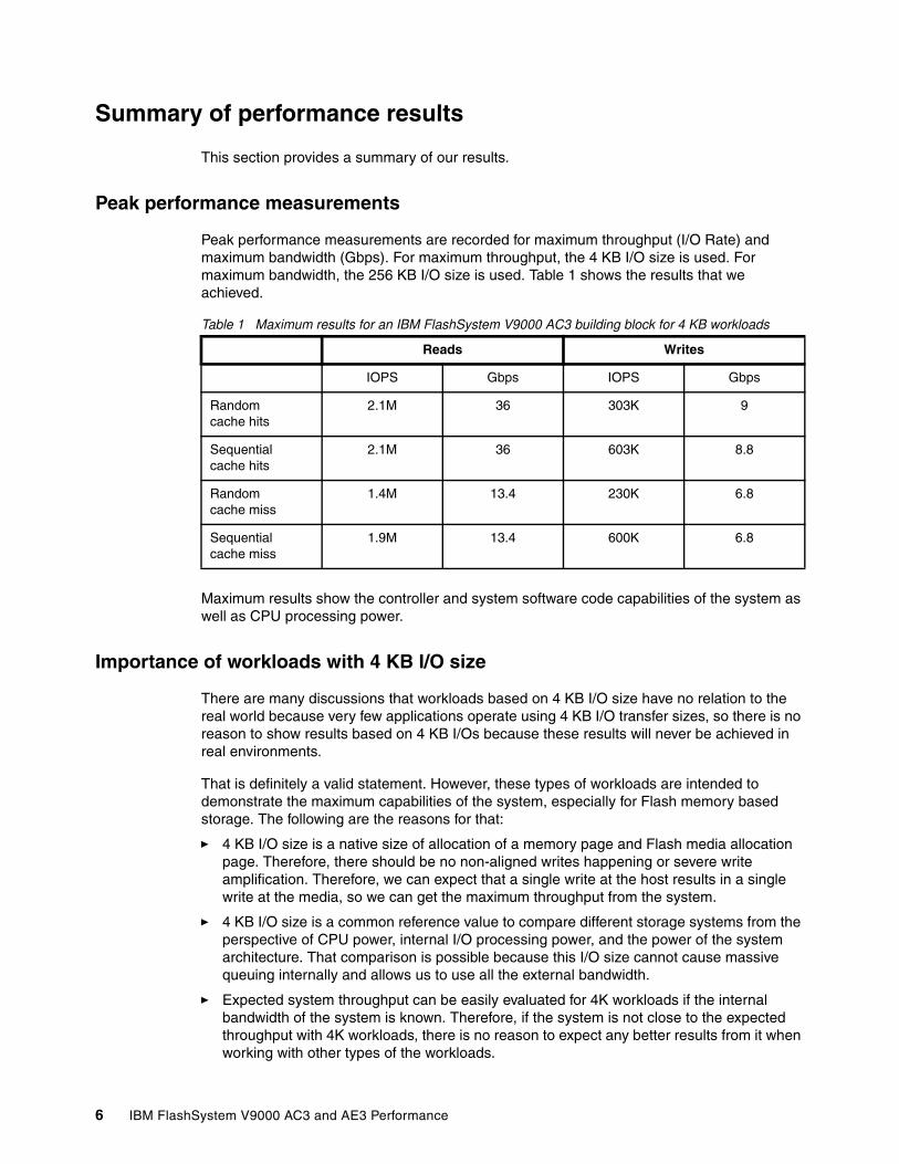
Peak performance measurements are recorded for maximum throughput (I/O Rate) and maximum bandwidth (Gbps). For maximum throughput, the 4 KB I/O size is used. For maximum bandwidth, the 256 KB I/O size is used. Table 1 shows the results that we achieved.
Table 1 Maximum results for an IBM FlashSystem V9000 AC3 building block for 4 KB workloads
Maximum results show the controller and system software code capabilities of the system as well as CPU processing power.
Importance of workloads with 4 KB I/O size
There are many discussions that workloads based on 4 KB I/O size have no relation to the real world because very few applications operate using 4 KB I/O transfer sizes, so there is no reason to show results based on 4 KB I/Os because these results will never be achieved in real environments.
That is definitely a valid statement. However, these types of workloads are intended to demonstrate the maximum capabilities of the system, especially for Flash memory based storage. The following are the reasons for that:
� 4 KB I/O size is a native size of allocation of a memory page and Flash media allocation page. Therefore, there should be no non-aligned writes happening or severe write amplification. Therefore, we can expect that a single write at the host results in a single write at the media, so we can get the maximum throughput from the system.
� 4 KB I/O size is a common reference value to compare different storage systems from the perspective of CPU power, internal I/O processing power, and the power of the system architecture. That comparison is possible because this I/O size cannot cause massive queuing internally and allows us to use all the external bandwidth.
� Expected system throughput can be easily evaluated for 4K workloads if the internal bandwidth of the system is known. Therefore, if the system is not close to the expected throughput with 4K workloads, there is no reason to expect any better results from it when working with other types of the workloads.
Reads Writes
IOPS Gbps IOPS Gbps
Randomcache hits
2.1M 36 303K 9
Sequential cache hits
2.1M 36 603K 8.8
Random cache miss
1.4M 13.4 230K 6.8
Sequentialcache miss
1.9M 13.4 600K 6.8
6 IBM FlashSystem V9000 AC3 and AE3 Performance
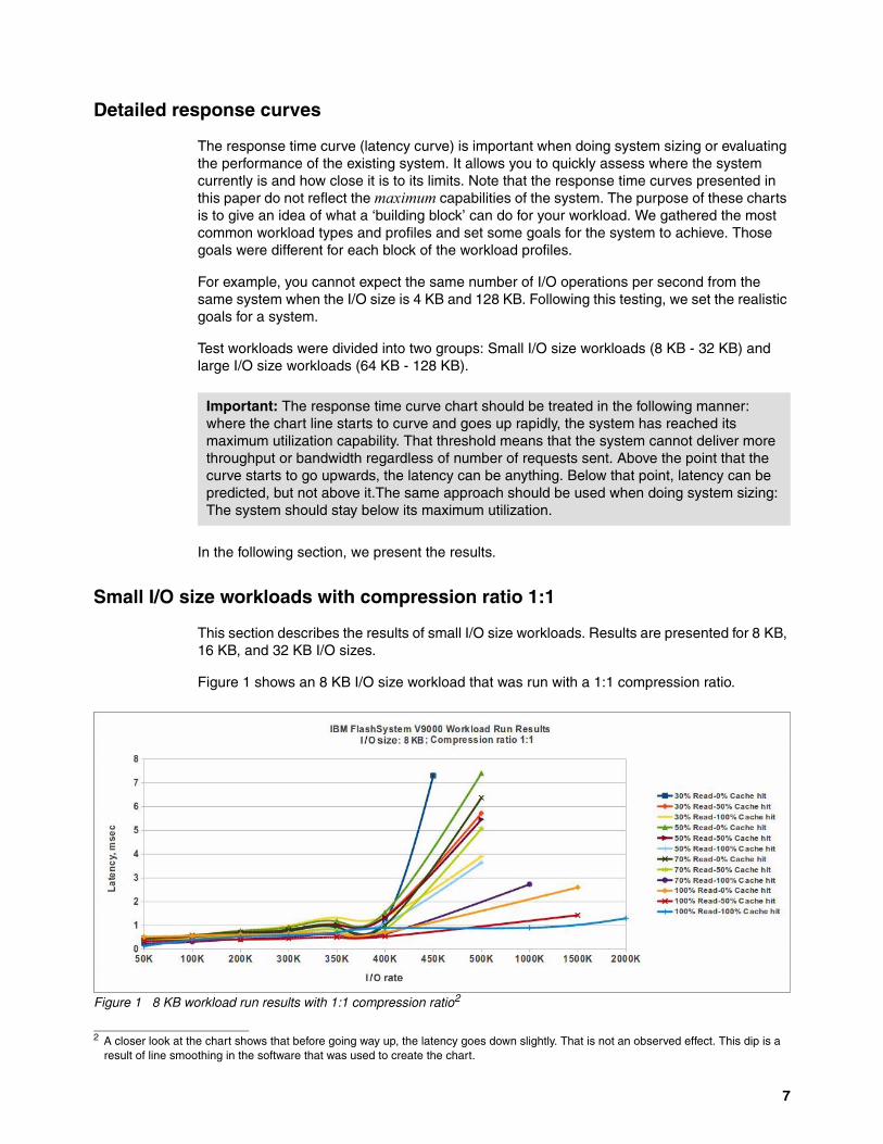
Detailed response curves
The response time curve (latency curve) is important when doing system sizing or evaluating the performance of the existing system. It allows you to quickly assess where the system currently is and how close it is to its limits. Note that the response time curves presented in this paper do not reflect the maximum capabilities of the system. The purpose of these charts is to give an idea of what a ‘building block’ can do for your workload. We gathered the most common workload types and profiles and set some goals for the system to achieve. Those goals were different for each block of the workload profiles.
For example, you cannot expect the same number of I/O operations per second from the same system when the I/O size is 4 KB and 128 KB. Following this testing, we set the realistic goals for a system.
Test workloads were divided into two groups: Small I/O size workloads (8 KB - 32 KB) and large I/O size workloads (64 KB - 128 KB).
In the following section, we present the results.
Small I/O size workloads with compression ratio 1:1
This section describes the results of small I/O size workloads. Results are presented for 8 KB, 16 KB, and 32 KB I/O sizes.
Figure 1 shows an 8 KB I/O size workload that was run with a 1:1 compression ratio.
Figure 1 8 KB workload run results with 1:1 compression ratio2
Important: The response time curve chart should be treated in the following manner: where the chart line starts to curve and goes up rapidly, the system has reached its maximum utilization capability. That threshold means that the system cannot deliver more throughput or bandwidth regardless of number of requests sent. Above the point that the curve starts to go upwards, the latency can be anything. Below that point, latency can be predicted, but not above it.The same approach should be used when doing system sizing: The system should stay below its maximum utilization.
2 A closer look at the chart shows that before going way up, the latency goes down slightly. That is not an observed effect. This dip is a result of line smoothing in the software that was used to create the chart.
7
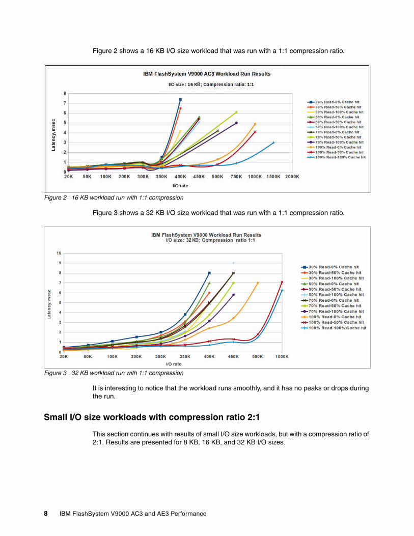
Figure 2 shows a 16 KB I/O size workload that was run with a 1:1 compression ratio.
Figure 2 16 KB workload run with 1:1 compression
Figure 3 shows a 32 KB I/O size workload that was run with a 1:1 compression ratio.
Figure 3 32 KB workload run with 1:1 compression
It is interesting to notice that the workload runs smoothly, and it has no peaks or drops during the run.
Small I/O size workloads with compression ratio 2:1
This section continues with results of small I/O size workloads, but with a compression ratio of 2:1. Results are presented for 8 KB, 16 KB, and 32 KB I/O sizes.
8 IBM FlashSystem V9000 AC3 and AE3 Performance

Figure 4 shows an 8 KB I/O size workload that was run with a 2:1 compression ratio.
Figure 4 8K compression ratio 2:1 workload run results
Figure 5 shows a 16 KB I/O size workload with a 2:1 compression ratio.
Figure 5 16 KB, compression ratio 2:1 workload run results
9

Figure 6 shows a 32 KB I/O size workload with a 2:1 compression ratio.
Figure 6 32 KB, compression ratio 2:1 workload run results
Large I/O size workloads
The best practice is to have large I/O size workloads with a minimum compression ratio of 2:1 where backend AE enclosures show the best performance capabilities and that allows us to have real capacity savings benefits3. We followed this best practice and provide results for a 2:1 compression ratio only.
The results presented are for workloads with I/O sizes of 64 KB and 128 KB.
Figure 7 shows a 64 K I/O size workload with a 2:1 compression ratio.
Figure 7 64 KB, compression ratio 2:1 workload run results
3 For more information, see Implementing IBM FlashSystem 900 Model AE3, SG24-8414.
10 IBM FlashSystem V9000 AC3 and AE3 Performance
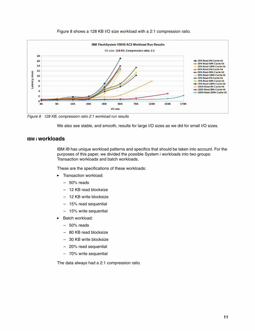
Figure 8 shows a 128 KB I/O size workload with a 2:1 compression ratio.
Figure 8 128 KB, compression ratio 2:1 workload run results
We also see stable, and smooth, results for large I/O sizes as we did for small I/O sizes.
IBM i workloads
IBM i® has unique workload patterns and specifics that should be taken into account. For the purposes of this paper, we divided the possible System i workloads into two groups: Transaction workloads and batch workloads.
These are the specifications of these workloads:
� Transaction workload:
– 50% reads
– 12 KB read blocksize
– 12 KB write blocksize
– 15% read sequential
– 15% write sequential
� Batch workload:
– 50% reads
– 80 KB read blocksize
– 30 KB write blocksize
– 20% read sequential
– 70% write sequential
The data always had a 2:1 compression ratio.
11
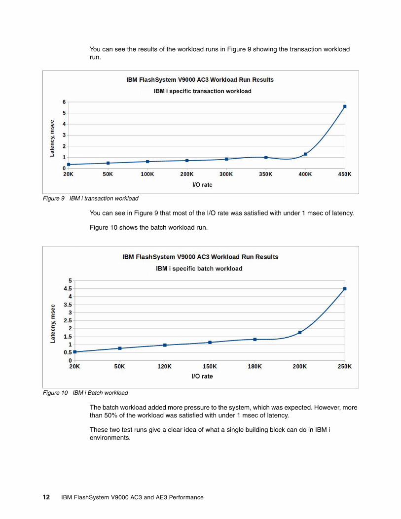
You can see the results of the workload runs in Figure 9 showing the transaction workload run.
Figure 9 IBM i transaction workload
You can see in Figure 9 that most of the I/O rate was satisfied with under 1 msec of latency.
Figure 10 shows the batch workload run.
Figure 10 IBM i Batch workload
The batch workload added more pressure to the system, which was expected. However, more than 50% of the workload was satisfied with under 1 msec of latency.
These two test runs give a clear idea of what a single building block can do in IBM i environments.
12 IBM FlashSystem V9000 AC3 and AE3 Performance
Results overview
The results included in this paper can be used for sizing and evaluation purposes.
For sizing purposes you can follow this approach:
� Find the workload profile that suits your workload best.
� Set the expected throughput/bandwidth value for the workload and find the estimated latency with that value.
� Set the expected latency value for the workload and find the throughput/bandwidth value that can be achieved.
� Keep in mind that the results presented were for the single building block. Estimate the required number of building blocks.
For a performance evaluation of the existing system, follow this approach:
� Find the workload profile that suits your workload the best.
� Find the existing latency, throughput, or bandwidth value.
� Get the current estimated level of utilization for your system.
� Keep in mind that the results presented were for the single building block. Normalize your workload to match a single block workload when doing your evaluation.
Deeper look at the results
The most popular question for IBM FlashSystems is “What I/O rate can we get with a latency of under 1 millisecond?” We can look at our results to answer this question.
Workloads with small I/O size
The results presented demonstrate that the system showed stability, and was able to achieve 80-90% of utilization while delivering less than a millisecond of latency, especially for workloads that benefit from cache memory. However, even workloads that are not so cache-friendly can keep system utilization up to 60-70% and stay under 1 millisecond of latency.
13

Figure 11 shows a 16 KB workload run and has a zone of 1 msec of latency highlighted. As you can see, it is about 90% utilization of the system.
Figure 11 Highlighted areas of latency of 1 msec and below for 16 KB workload, compression ratio 2:1
Workloads with large I/O size
As indicated in “Detailed response curves” on page 7, small I/O operations are very latency sensitive, whereas larger I/O operations are throughput-oriented, and latency increases naturally with the longer data transfer. Therefore, if the indicator for small I/O size workloads is 1 millisecond, for large I/O size workloads such an indicator should be 3 milliseconds.
We can find that, depending on the cache hit ratio, the system is capable of keeping below 3 milliseconds even with 100% utilization.
Figure 12 shows system stability with a workload of 64 KB I/O size.
Figure 12 Highlighted areas of latency of 3 msec and below for 64 KB workload, compression ratio 2:1
14 IBM FlashSystem V9000 AC3 and AE3 Performance

Comparing the compression ratios
The existing best practices suggest that the system benefits from workloads that have a 2:1 compression ratio and above, and our test runs confirmed that. Compression ratios below that value can lead to overutilization of system components and lower the expected results of I/O rate or bandwidth. Good compression ratios allowed us to have less loaded backend enclosures in IBM FlashSystem V9000 AC2, and allowed us to have less write amplification at the backend enclosures in IBM FlashSystem V9000 AC3.
Compression provides benefits for small I/O size and large I/O size workloads. Small I/O size workloads do not see any significant increase in latency with compression and have capacity savings benefits at the same time. As I/O size gets larger, we can see that at the same I/O rate value that latency drops for workloads with compressible I/O patterns. For more information, see Figure 3 on page 8 and Figure 6 on page 10.
For the same I/O rate point (350K), latency for the compressible workload is about 1 msec, when for the non-compressible workload latency is 1.5 - 4 msec depending on the workload specification, which confirms existing best practices.
Solution configuration and sizing guidelines
The introduction of a new design of IBM FlashSystem V9000 and the introduction of compression capabilities at the enclosure level has changed the way that solution sizing should be performed.
The previous design had the following major points for sizing:
� One AC node was the one compression engine for sizing purposes.
� One I/O Group was the one compression domain for sizing purposes.
� Compression limits were the main factor for solution sizings. forcing us to have 2 AC x 1 AE (two AC nodes x 1 AE node) as a single building block. That configuration allowed vertical scaling of the solution only. If more compression power was required, more building blocks had to be purchased. If more capacity was required, again, more building blocks had to be purchased because the more capacity used might overload existing compression capabilities.
The new IBM FlashSystem V9000 design includes these major points for solution sizing:
� Compression engines are now moved to Flash Modules, and a single Flash Module becomes a single compression engine for sizing purposes. If more compression power is needed, more modules can be used.
� Flash enclosure becomes a single compression domain and should be sized accordingly4.
� Horizontal and vertical scaling of a solution is now possible. More AE enclosures can be added to a single I/O group without risking overloading compression in AC nodes.
� There is no specifically defined ‘building block’ concept. However, still generally follow a 2 AC x 1 AE or 2 AC x 2 AE approach when sizing a solution.
4 Sizing guidelines of IBM FlashSystem 900 AE3 model are out of the intended scope of this paper. IBM employees can use the following guide for reference: http://w3.ibm.com/support/techdocs/atsmastr.nsf/WebIndex/PRS5377
15

An overall scaling approach for IBM FlashSystem V9000 is presented in Figure 13.
Figure 13 IBM FlashSystem V9000 scaling approach
Solution sizing workflow
The solution sizing workflow follows the existing best practices for IBM FlashSystem V9000 with the difference that a compression utilization evaluation should be done for Flash modules instead of Real-time Compression cards in AC nodes. See Figure 14 for reference.
Figure 14 IBM FlashSystem V9000 sizing workflow chart
Important: Remember to keep component utilization below 50% when doing system sizing to ensure minimal latency and have minimal effect on the performance of the system when component failure or maintenance actions occur.
16 IBM FlashSystem V9000 AC3 and AE3 Performance
A detailed approach to sizing using Disk Magic can be found in “System sizing and modeling in Disk Magic” on page 17.
Conclusion
This paper has described common IBM FlashSystem V9000 AE3 configuration behavior under the most common workloads. We assumed that configuration to be the most commonly encountered in client environments, as are the set of workloads selected. Our testing showed the following results:
� The system demonstrated the expected stability under workloads of large and small I/Os. There were no I/O drops or pauses related to the internal I/O processing or cache destages.
� The major outcome found was that the configuration selected as the major building block could satisfy most of the requirements in most environments across the market.
� The new design allowed us to have better results with cache friendly workloads and, at the same time, improved results with non-cache friendly workloads. Even when utilization of the backend enclosures was close to the upper limits, the cache allowed us to improve latency results.
� Compression proved to be a serious contributor to the improvement of the results. It was demonstrated that with the same I/O rate, workloads with a compression ratio of 2:1 had lower latency than the ones that had a compression ratio of 1:1.
� The new design of IBM FlashSystem V9000 AC3 allowed us to have better results with the same workloads compared to the AC2 model.
The best results in performance can be achieved with proper planning and sizing of the solution. Major methods of sizing and planning were reviewed in this paper. For more information about best practices, see the following publications:
� Implementing the IBM System Storage SAN Volume Controller with IBM Spectrum Virtualize V8.1, SG24-7933
� Implementing the IBM Storwize V7000 with IBM Spectrum Virtualize V8.1, SG24-7938
� Implementing IBM FlashSystem 900 Model AE3, SG24-8414
System sizing and modeling in Disk Magic
Figure 14 on page 16 shows that it is important to use the IBM Disk Magic tool to properly size a solution.
Use the following workflow as a reference:
� Start the Storage Virtualization Wizard.
� Use IBM FlashSystem 900-AE3 as a storage system. Set the capacity and ports settings (port speed and number of ports).
� Input your workload specification and used capacity.
� Do not enable compression at the SVC 2145-SV1 level.
� Set the compression ratio for IBM FlashSystem 900-AE3 systems in the Open Workload tab, as shown in Figure 15.
17
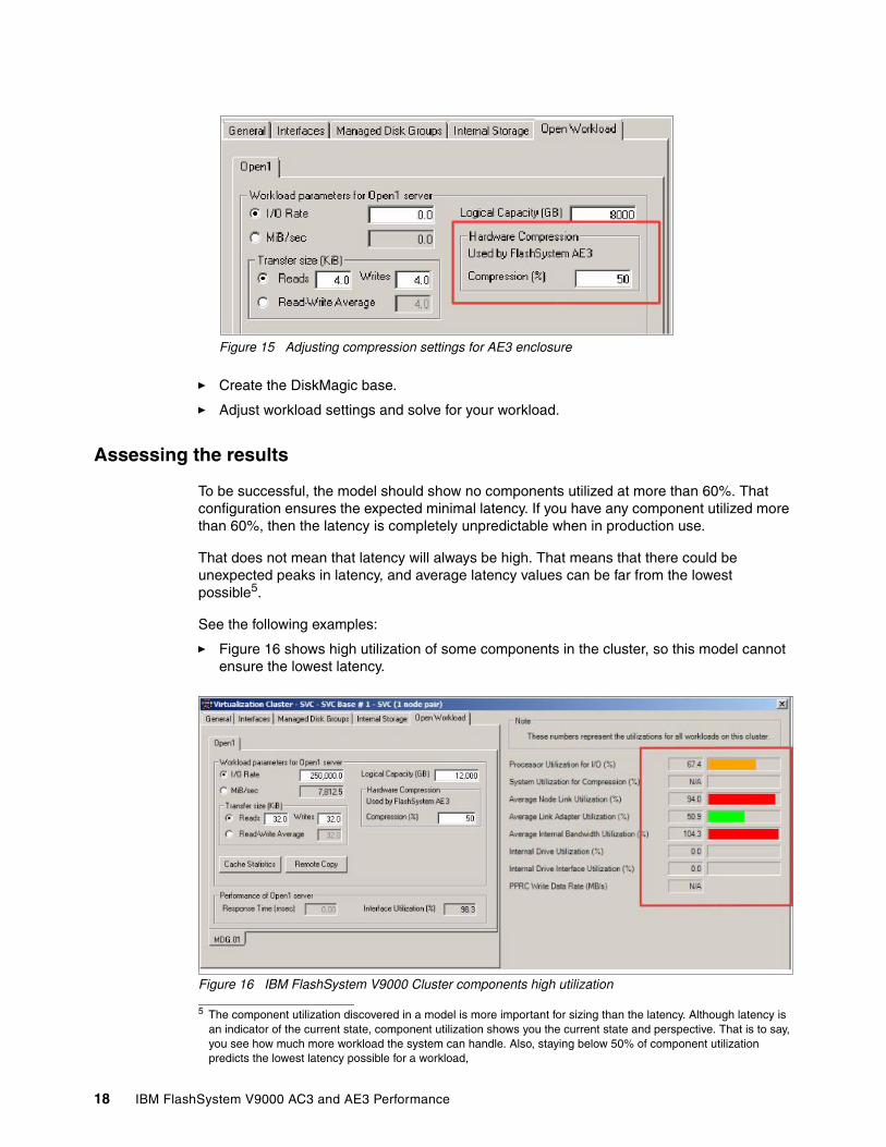
Figure 15 Adjusting compression settings for AE3 enclosure
� Create the DiskMagic base.
� Adjust workload settings and solve for your workload.
Assessing the results
To be successful, the model should show no components utilized at more than 60%. That configuration ensures the expected minimal latency. If you have any component utilized more than 60%, then the latency is completely unpredictable when in production use.
That does not mean that latency will always be high. That means that there could be unexpected peaks in latency, and average latency values can be far from the lowest possible5.
See the following examples:
� Figure 16 shows high utilization of some components in the cluster, so this model cannot ensure the lowest latency.
Figure 16 IBM FlashSystem V9000 Cluster components high utilization
5 The component utilization discovered in a model is more important for sizing than the latency. Although latency is an indicator of the current state, component utilization shows you the current state and perspective. That is to say, you see how much more workload the system can handle. Also, staying below 50% of component utilization predicts the lowest latency possible for a workload,
18 IBM FlashSystem V9000 AC3 and AE3 Performance

� Figure 17 shows component utilization for IBM FlashSystem 900-AE3. There are some components utilized higher than expected. The results of this modeling should be reevaluated or system settings should be adjusted.
Figure 17 IBM FlashSystem 900-AE3 component utilization
Keeping component utilization below 50% or 60% is proven to be the most successful way of modeling IBM FlashSystem V9000 solutions.
Authors
This paper was produced by a team of specialists from around the world working at Hursley Labs, UK.
Denis Senin works for IBM Systems at Hursley Labs, UK.
Thanks to the following people for their contributions to this project:
Denis FrankIBM Systems, Hursley Labs, UK
Atif SyedIBM Systems, Hursley Labs, UK
Jana JamsekIBM Slovenia
Matt SmithIBM Systems, UK
This project was managed by:
Jon TateIBM ITSO, UK
Now you can become a published author, too!
Here's an opportunity to spotlight your skills, grow your career, and become a published author—all at the same time! Join an ITSO residency project and help write a book in your area of expertise, while honing your experience using leading-edge technologies. Your efforts will help to increase product acceptance and customer satisfaction, as you expand your network of technical contacts and relationships. Residencies run from two to six weeks in length, and you can participate either in person or as a remote resident working from your home base.
19

Find out more about the residency program, browse the residency index, and apply online at:
ibm.com/redbooks/residencies.html
Stay connected to IBM Redbooks
� Find us on Facebook:
http://www.facebook.com/IBMRedbooks
� Follow us on Twitter:
http://twitter.com/ibmredbooks
� Look for us on LinkedIn:
http://www.linkedin.com/groups?home=&gid=2130806
� Explore new Redbooks publications, residencies, and workshops with the IBM Redbooks weekly newsletter:
https://www.redbooks.ibm.com/Redbooks.nsf/subscribe?OpenForm
� Stay current on recent Redbooks publications with RSS Feeds:
http://www.redbooks.ibm.com/rss.html
20 IBM FlashSystem V9000 AC3 and AE3 Performance

Notices
This information was developed for products and services offered in the US. This material might be available from IBM in other languages. However, you may be required to own a copy of the product or product version in that language in order to access it.
IBM may not offer the products, services, or features discussed in this document in other countries. Consult your local IBM representative for information on the products and services currently available in your area. Any reference to an IBM product, program, or service is not intended to state or imply that only that IBM product, program, or service may be used. Any functionally equivalent product, program, or service that does not infringe any IBM intellectual property right may be used instead. However, it is the user’s responsibility to evaluate and verify the operation of any non-IBM product, program, or service.
IBM may have patents or pending patent applications covering subject matter described in this document. The furnishing of this document does not grant you any license to these patents. You can send license inquiries, in writing, to:IBM Director of Licensing, IBM Corporation, North Castle Drive, MD-NC119, Armonk, NY 10504-1785, US
INTERNATIONAL BUSINESS MACHINES CORPORATION PROVIDES THIS PUBLICATION “AS IS” WITHOUT WARRANTY OF ANY KIND, EITHER EXPRESS OR IMPLIED, INCLUDING, BUT NOT LIMITED TO, THE IMPLIED WARRANTIES OF NON-INFRINGEMENT, MERCHANTABILITY OR FITNESS FOR A PARTICULAR PURPOSE. Some jurisdictions do not allow disclaimer of express or implied warranties in certain transactions, therefore, this statement may not apply to you.
This information could include technical inaccuracies or typographical errors. Changes are periodically made to the information herein; these changes will be incorporated in new editions of the publication. IBM may make improvements and/or changes in the product(s) and/or the program(s) described in this publication at any time without notice.
Any references in this information to non-IBM websites are provided for convenience only and do not in any manner serve as an endorsement of those websites. The materials at those websites are not part of the materials for this IBM product and use of those websites is at your own risk.
IBM may use or distribute any of the information you provide in any way it believes appropriate without incurring any obligation to you.
The performance data and client examples cited are presented for illustrative purposes only. Actual performance results may vary depending on specific configurations and operating conditions.
Information concerning non-IBM products was obtained from the suppliers of those products, their published announcements or other publicly available sources. IBM has not tested those products and cannot confirm the accuracy of performance, compatibility or any other claims related to non-IBM products. Questions on the capabilities of non-IBM products should be addressed to the suppliers of those products.
Statements regarding IBM’s future direction or intent are subject to change or withdrawal without notice, and represent goals and objectives only.
This information contains examples of data and reports used in daily business operations. To illustrate them as completely as possible, the examples include the names of individuals, companies, brands, and products. All of these names are fictitious and any similarity to actual people or business enterprises is entirely coincidental.
COPYRIGHT LICENSE:
This information contains sample application programs in source language, which illustrate programming techniques on various operating platforms. You may copy, modify, and distribute these sample programs in any form without payment to IBM, for the purposes of developing, using, marketing or distributing application programs conforming to the application programming interface for the operating platform for which the sample programs are written. These examples have not been thoroughly tested under all conditions. IBM, therefore, cannot guarantee or imply reliability, serviceability, or function of these programs. The sample programs are provided “AS IS”, without warranty of any kind. IBM shall not be liable for any damages arising out of your use of the sample programs.
© Copyright IBM Corp. 2018. All rights reserved. 21

Trademarks
IBM, the IBM logo, and ibm.com are trademarks or registered trademarks of International Business Machines Corporation, registered in many jurisdictions worldwide. Other product and service names might be trademarks of IBM or other companies. A current list of IBM trademarks is available on the web at “Copyright and trademark information” at http://www.ibm.com/legal/copytrade.shtml
The following terms are trademarks or registered trademarks of International Business Machines Corporation, and might also be trademarks or registered trademarks in other countries.
HyperSwap®IBM®IBM FlashSystem®IBM Spectrum™
IBM Spectrum Virtualize™Real-time Compression™Redbooks®Redpaper™
Redbooks (logo) ®System i®
The following terms are trademarks of other companies:
Other company, product, or service names may be trademarks or service marks of others.
22 IBM FlashSystem V9000 AC3 and AE3 Performance


ibm.com/redbooks
Printed in U.S.A.
Back cover
ISBN 0738456640
REDP-5480-00
®