ibm flashsystem a9000 and a9000r, ibm xiv, and ibm ... · ibm flashsystem a9000 and a9000r, ibm...
TRANSCRIPT
Redpaper
Front cover
IBM FlashSystem A9000 and A9000R, IBM XIV, and IBM Spectrum Accelerate with IBM SAN Volume Controller Best Practices
Markus Oscheka
Stephen Solewin


International Technical Support Organization
IBM FlashSystem A9000 and A9000R, IBM XIV, and IBM Spectrum Accelerate with IBM SVC Best Practices
January 2018
REDP-5408-01

© Copyright International Business Machines Corporation 2016, 2018. All rights reserved.Note to U.S. Government Users Restricted Rights -- Use, duplication or disclosure restricted by GSA ADP ScheduleContract with IBM Corp.
Second Edition (January 2018)
This edition applies to the IBM Spectum Accelerate family, including IBM XIV Storage System Gen 3, IBM FlashSystem A9000 and IBM FlashSystem A9000R, with software Version 12.2.0 or later, and IBM Spectrum Accelerate Version 11.5.4 attaching to IBM SAN Volume Controller software code level 7.8.1 and higher.
Note: Before using this information and the product it supports, read the information in “Notices” on page vii.
Contents
Notices . . . . . . . . . . . . . . . . . . . . . . . . . . . . . . . . . . . . . . . . . . . . . . . . . . . . . . . . . . . . . . . . . viiTrademarks . . . . . . . . . . . . . . . . . . . . . . . . . . . . . . . . . . . . . . . . . . . . . . . . . . . . . . . . . . . . . viii
Preface . . . . . . . . . . . . . . . . . . . . . . . . . . . . . . . . . . . . . . . . . . . . . . . . . . . . . . . . . . . . . . . . . ixAuthors. . . . . . . . . . . . . . . . . . . . . . . . . . . . . . . . . . . . . . . . . . . . . . . . . . . . . . . . . . . . . . . . . . ixNow you can become a published author, too! . . . . . . . . . . . . . . . . . . . . . . . . . . . . . . . . . . . ixComments welcome. . . . . . . . . . . . . . . . . . . . . . . . . . . . . . . . . . . . . . . . . . . . . . . . . . . . . . . . .xStay connected to IBM Redbooks . . . . . . . . . . . . . . . . . . . . . . . . . . . . . . . . . . . . . . . . . . . . . .x
Chapter 1. IBM Spectrum Accelerate family and IBM System Storage SAN Volume Controller attachment. . . . . . . . . . . . . . . . . . . . . . . . . . . . . . . . . . . . . . . . . . . . 1
1.1 Benefits of combining storage systems. . . . . . . . . . . . . . . . . . . . . . . . . . . . . . . . . . . . . . 21.2 Data reduction in storage systems that are attached to SAN Volume Controller . . . . . . 2
1.2.1 Data reduction considerations for the XIV Gen3 system . . . . . . . . . . . . . . . . . . . . 21.2.2 Data reduction considerations for IBM FlashSystem A9000 or IBM FlashSystem
A9000R. . . . . . . . . . . . . . . . . . . . . . . . . . . . . . . . . . . . . . . . . . . . . . . . . . . . . . . . . . 3
Chapter 2. IBM XIV Gen3 with IBM System Storage SAN Volume Controller . . . . . . . . 52.1 Summary of steps for attaching an XIV system to a SAN Volume Controller . . . . . . . . . 62.2 XIV and SAN Volume Controller interoperability . . . . . . . . . . . . . . . . . . . . . . . . . . . . . . . 6
2.2.1 Firmware versions. . . . . . . . . . . . . . . . . . . . . . . . . . . . . . . . . . . . . . . . . . . . . . . . . . 62.2.2 Copy functions . . . . . . . . . . . . . . . . . . . . . . . . . . . . . . . . . . . . . . . . . . . . . . . . . . . . 7
2.3 Zoning setup . . . . . . . . . . . . . . . . . . . . . . . . . . . . . . . . . . . . . . . . . . . . . . . . . . . . . . . . . . 82.3.1 Capacity on Demand . . . . . . . . . . . . . . . . . . . . . . . . . . . . . . . . . . . . . . . . . . . . . . . 92.3.2 Determining XIV WWPNs . . . . . . . . . . . . . . . . . . . . . . . . . . . . . . . . . . . . . . . . . . . . 92.3.3 Hardware dependencies . . . . . . . . . . . . . . . . . . . . . . . . . . . . . . . . . . . . . . . . . . . . 112.3.4 Sharing XIV host ports . . . . . . . . . . . . . . . . . . . . . . . . . . . . . . . . . . . . . . . . . . . . . 112.3.5 Zoning rules . . . . . . . . . . . . . . . . . . . . . . . . . . . . . . . . . . . . . . . . . . . . . . . . . . . . . 11
2.4 Volume size for an XIV system with SAN Volume Controller . . . . . . . . . . . . . . . . . . . . 122.4.1 SCSI queue depth considerations . . . . . . . . . . . . . . . . . . . . . . . . . . . . . . . . . . . . 122.4.2 XIV volume sizes . . . . . . . . . . . . . . . . . . . . . . . . . . . . . . . . . . . . . . . . . . . . . . . . . 142.4.3 Creating XIV volumes with the same size as SAN Volume Controller VDisks . . . 162.4.4 Creating managed disk groups . . . . . . . . . . . . . . . . . . . . . . . . . . . . . . . . . . . . . . . 162.4.5 SAN Volume Controller MDisk group extent sizes . . . . . . . . . . . . . . . . . . . . . . . . 17
2.5 Using an XIV system for SAN Volume Controller quorum disks . . . . . . . . . . . . . . . . . . 182.6 Understanding SAN Volume Controller controller path values . . . . . . . . . . . . . . . . . . . 182.7 Configuring an XIV system for attachment to SAN Volume Controller . . . . . . . . . . . . . 19
2.7.1 XIV setup . . . . . . . . . . . . . . . . . . . . . . . . . . . . . . . . . . . . . . . . . . . . . . . . . . . . . . . 192.7.2 SAN Volume Controller setup steps . . . . . . . . . . . . . . . . . . . . . . . . . . . . . . . . . . . 24
Chapter 3. IBM FlashSystem A9000 or IBM FlashSystem A9000R with SAN Volume Controller. . . . . . . . . . . . . . . . . . . . . . . . . . . . . . . . . . . . . . . . . . . . . . . . . . . . . 29
3.1 Summary of steps . . . . . . . . . . . . . . . . . . . . . . . . . . . . . . . . . . . . . . . . . . . . . . . . . . . . . 303.2 IBM FlashSystem A9000 or IBM FlashSystem A9000R and SAN Volume Controller
interoperability . . . . . . . . . . . . . . . . . . . . . . . . . . . . . . . . . . . . . . . . . . . . . . . . . . . . . . . 303.2.1 Firmware versions. . . . . . . . . . . . . . . . . . . . . . . . . . . . . . . . . . . . . . . . . . . . . . . . . 30
3.3 Zoning considerations . . . . . . . . . . . . . . . . . . . . . . . . . . . . . . . . . . . . . . . . . . . . . . . . . . 32
© Copyright IBM Corp. 2016, 2018. All rights reserved. iii
3.3.1 Determining IBM FlashSystem A9000 or IBM FlashSystem A9000R worldwide port names. . . . . . . . . . . . . . . . . . . . . . . . . . . . . . . . . . . . . . . . . . . . . . . . . . . . . . . . . . 33
3.3.2 Sharing IBM FlashSystem A9000 or IBM FlashSystem A9000R host ports . . . . . 343.3.3 Zoning rules . . . . . . . . . . . . . . . . . . . . . . . . . . . . . . . . . . . . . . . . . . . . . . . . . . . . . 34
3.4 Volume size for IBM FlashSystem A9000 or IBM FlashSystem A9000R with SAN Volume Controller . . . . . . . . . . . . . . . . . . . . . . . . . . . . . . . . . . . . . . . . . . . . . . . . . . . . . . . . . . . 35
3.4.1 SCSI queue depth considerations . . . . . . . . . . . . . . . . . . . . . . . . . . . . . . . . . . . . 363.4.2 Creating IBM FlashSystem A9000 or IBM FlashSystem A9000R volumes that are the
same size as SAN Volume Controller VDisks . . . . . . . . . . . . . . . . . . . . . . . . . . . 363.4.3 Creating managed disk groups . . . . . . . . . . . . . . . . . . . . . . . . . . . . . . . . . . . . . . . 363.4.4 SAN Volume Controller MDisk group extent sizes . . . . . . . . . . . . . . . . . . . . . . . . 37
3.5 SAN Volume Controller controller path values . . . . . . . . . . . . . . . . . . . . . . . . . . . . . . . 383.6 Configuring IBM FlashSystem A9000 or IBM FlashSystem A9000R for SAN Volume
Controller attachment . . . . . . . . . . . . . . . . . . . . . . . . . . . . . . . . . . . . . . . . . . . . . . . . . . 403.6.1 IBM FlashSystem A9000 or IBM FlashSystem A9000R setup . . . . . . . . . . . . . . . 403.6.2 SAN Volume Controller setup steps . . . . . . . . . . . . . . . . . . . . . . . . . . . . . . . . . . . 44
Chapter 4. IBM Spectrum Accelerate with IBM System Storage SAN Volume Controller and IBM Storwize V7000. . . . . . . . . . . . . . . . . . . . . . . . . . . . . . . . . . . . . . . . . 47
4.1 Summary of steps for attaching an IBM Spectrum Accelerate system to a Storwize V7000 system . . . . . . . . . . . . . . . . . . . . . . . . . . . . . . . . . . . . . . . . . . . . . . . . . . . . . . . . . . . . . 48
4.2 IBM Spectrum Accelerate and Storwize V7000 interoperability . . . . . . . . . . . . . . . . . . 484.2.1 Firmware versions. . . . . . . . . . . . . . . . . . . . . . . . . . . . . . . . . . . . . . . . . . . . . . . . . 484.2.2 Copy functions . . . . . . . . . . . . . . . . . . . . . . . . . . . . . . . . . . . . . . . . . . . . . . . . . . . 49
4.3 iSCSI setup . . . . . . . . . . . . . . . . . . . . . . . . . . . . . . . . . . . . . . . . . . . . . . . . . . . . . . . . . . 504.4 Volume size for an IBM Spectrum Accelerate system with SAN Volume Controller and
Storwize V7000 systems . . . . . . . . . . . . . . . . . . . . . . . . . . . . . . . . . . . . . . . . . . . . . . . 514.5 Configuring IBM Spectrum Accelerate for attachment to Storwize V7000 . . . . . . . . . . 52
4.5.1 IBM Spectrum Accelerate setup . . . . . . . . . . . . . . . . . . . . . . . . . . . . . . . . . . . . . . 524.5.2 Storwize V7000 setup steps . . . . . . . . . . . . . . . . . . . . . . . . . . . . . . . . . . . . . . . . . 57
Chapter 5. Data movement concepts: SAN Volume Controller and the IBM Spectrum Accelerate family . . . . . . . . . . . . . . . . . . . . . . . . . . . . . . . . . . . . . . . . . . . . . . 63
5.1 Data movement strategies . . . . . . . . . . . . . . . . . . . . . . . . . . . . . . . . . . . . . . . . . . . . . . 645.1.1 Using SAN Volume Controller migration to move data . . . . . . . . . . . . . . . . . . . . . 645.1.2 Using VDisk mirroring to move the data . . . . . . . . . . . . . . . . . . . . . . . . . . . . . . . . 645.1.3 Using SAN Volume Controller migration with Image mode. . . . . . . . . . . . . . . . . . 65
5.2 Using SAN Volume Controller or Storwize V7000 migration to move data to an IBM Spectrum Accelerate family system . . . . . . . . . . . . . . . . . . . . . . . . . . . . . . . . . . . . . . . 66
5.2.1 Determining the required extent size and VDisk candidates. . . . . . . . . . . . . . . . . 665.2.2 Creating the MDisk group . . . . . . . . . . . . . . . . . . . . . . . . . . . . . . . . . . . . . . . . . . . 675.2.3 Migration . . . . . . . . . . . . . . . . . . . . . . . . . . . . . . . . . . . . . . . . . . . . . . . . . . . . . . . . 68
5.3 Using VDisk mirroring to move the data . . . . . . . . . . . . . . . . . . . . . . . . . . . . . . . . . . . . 695.3.1 Determining the required extent size and VDisk candidates. . . . . . . . . . . . . . . . . 695.3.2 Creating the MDisk group . . . . . . . . . . . . . . . . . . . . . . . . . . . . . . . . . . . . . . . . . . . 695.3.3 Setting up the I/O group for mirroring . . . . . . . . . . . . . . . . . . . . . . . . . . . . . . . . . . 695.3.4 Creating the mirror . . . . . . . . . . . . . . . . . . . . . . . . . . . . . . . . . . . . . . . . . . . . . . . . 705.3.5 Removing or splitting the VDisk copy . . . . . . . . . . . . . . . . . . . . . . . . . . . . . . . . . . 73
5.4 Using SAN Volume Controller migration with Image mode. . . . . . . . . . . . . . . . . . . . . . 755.4.1 Creating Image mode destination volumes. . . . . . . . . . . . . . . . . . . . . . . . . . . . . . 755.4.2 Migrating the VDisk to Image mode . . . . . . . . . . . . . . . . . . . . . . . . . . . . . . . . . . . 765.4.3 Removing the Image mode VDisk. . . . . . . . . . . . . . . . . . . . . . . . . . . . . . . . . . . . . 795.4.4 Migration from Image mode to managed mode . . . . . . . . . . . . . . . . . . . . . . . . . . 815.4.5 Removing a transitional MDisk group . . . . . . . . . . . . . . . . . . . . . . . . . . . . . . . . . . 83
iv IBM FlashSystem A9000 and A9000R, IBM XIV, and IBM Spectrum Accelerate with IBM SVC Best Practices
5.4.6 Using transitional space as managed space. . . . . . . . . . . . . . . . . . . . . . . . . . . . . 835.4.7 Removing non IBM Spectrum Accelerate family MDisks . . . . . . . . . . . . . . . . . . . 83
5.5 Future configuration tasks. . . . . . . . . . . . . . . . . . . . . . . . . . . . . . . . . . . . . . . . . . . . . . . 845.5.1 Adding capacity to the IBM Spectrum Accelerate family system . . . . . . . . . . . . . 84
5.6 Implementation checklist for the SAN Volume Controller with IBM Spectrum Accelerate family configuration. . . . . . . . . . . . . . . . . . . . . . . . . . . . . . . . . . . . . . . . . . . . . . . . . . . . 84
Related publications . . . . . . . . . . . . . . . . . . . . . . . . . . . . . . . . . . . . . . . . . . . . . . . . . . . . . 87IBM Redbooks . . . . . . . . . . . . . . . . . . . . . . . . . . . . . . . . . . . . . . . . . . . . . . . . . . . . . . . . . . . 87Help from IBM . . . . . . . . . . . . . . . . . . . . . . . . . . . . . . . . . . . . . . . . . . . . . . . . . . . . . . . . . . . 87
Contents v

vi IBM FlashSystem A9000 and A9000R, IBM XIV, and IBM Spectrum Accelerate with IBM SVC Best Practices
Notices
This information was developed for products and services offered in the US. This material might be available from IBM in other languages. However, you may be required to own a copy of the product or product version in that language in order to access it.
IBM may not offer the products, services, or features discussed in this document in other countries. Consult your local IBM representative for information on the products and services currently available in your area. Any reference to an IBM product, program, or service is not intended to state or imply that only that IBM product, program, or service may be used. Any functionally equivalent product, program, or service that does not infringe any IBM intellectual property right may be used instead. However, it is the user’s responsibility to evaluate and verify the operation of any non-IBM product, program, or service.
IBM may have patents or pending patent applications covering subject matter described in this document. The furnishing of this document does not grant you any license to these patents. You can send license inquiries, in writing, to:IBM Director of Licensing, IBM Corporation, North Castle Drive, MD-NC119, Armonk, NY 10504-1785, US
INTERNATIONAL BUSINESS MACHINES CORPORATION PROVIDES THIS PUBLICATION “AS IS” WITHOUT WARRANTY OF ANY KIND, EITHER EXPRESS OR IMPLIED, INCLUDING, BUT NOT LIMITED TO, THE IMPLIED WARRANTIES OF NON-INFRINGEMENT, MERCHANTABILITY OR FITNESS FOR A PARTICULAR PURPOSE. Some jurisdictions do not allow disclaimer of express or implied warranties in certain transactions, therefore, this statement may not apply to you.
This information could include technical inaccuracies or typographical errors. Changes are periodically made to the information herein; these changes will be incorporated in new editions of the publication. IBM may make improvements and/or changes in the product(s) and/or the program(s) described in this publication at any time without notice.
Any references in this information to non-IBM websites are provided for convenience only and do not in any manner serve as an endorsement of those websites. The materials at those websites are not part of the materials for this IBM product and use of those websites is at your own risk.
IBM may use or distribute any of the information you provide in any way it believes appropriate without incurring any obligation to you.
The performance data and client examples cited are presented for illustrative purposes only. Actual performance results may vary depending on specific configurations and operating conditions.
Information concerning non-IBM products was obtained from the suppliers of those products, their published announcements or other publicly available sources. IBM has not tested those products and cannot confirm the accuracy of performance, compatibility or any other claims related to non-IBM products. Questions on the capabilities of non-IBM products should be addressed to the suppliers of those products.
Statements regarding IBM’s future direction or intent are subject to change or withdrawal without notice, and represent goals and objectives only.
This information contains examples of data and reports used in daily business operations. To illustrate them as completely as possible, the examples include the names of individuals, companies, brands, and products. All of these names are fictitious and any similarity to actual people or business enterprises is entirely coincidental.
COPYRIGHT LICENSE:
This information contains sample application programs in source language, which illustrate programming techniques on various operating platforms. You may copy, modify, and distribute these sample programs in any form without payment to IBM, for the purposes of developing, using, marketing or distributing application programs conforming to the application programming interface for the operating platform for which the sample programs are written. These examples have not been thoroughly tested under all conditions. IBM, therefore, cannot guarantee or imply reliability, serviceability, or function of these programs. The sample programs are provided “AS IS”, without warranty of any kind. IBM shall not be liable for any damages arising out of your use of the sample programs.
© Copyright IBM Corp. 2016, 2018. All rights reserved. vii
Trademarks
IBM, the IBM logo, and ibm.com are trademarks or registered trademarks of International Business Machines Corporation, registered in many jurisdictions worldwide. Other product and service names might be trademarks of IBM or other companies. A current list of IBM trademarks is available on the web at “Copyright and trademark information” at http://www.ibm.com/legal/copytrade.shtml
The following terms are trademarks or registered trademarks of International Business Machines Corporation, and might also be trademarks or registered trademarks in other countries.
Easy Tier®FlashCopy®HyperSwap®IBM®IBM FlashSystem®IBM Spectrum™
IBM Spectrum Accelerate™IBM Spectrum Storage™IBM Spectrum Virtualize™Real-time Compression™Redbooks®Redpaper™
Redbooks (logo) ®Storwize®System Storage®XIV®
The following terms are trademarks of other companies:
Linear Tape-Open, LTO, the LTO Logo and the Ultrium logo are trademarks of HP, IBM Corp. and Quantum in the U.S. and other countries.
UNIX is a registered trademark of The Open Group in the United States and other countries.
Other company, product, or service names may be trademarks or service marks of others.
viii IBM FlashSystem A9000 and A9000R, IBM XIV, and IBM Spectrum Accelerate with IBM SVC Best Practices
Preface
This IBM® Redpaper™ publication describes preferred practices for attaching members of the IBM Spectrum™ Accelerate family, including the IBM XIV® Gen3 Storage System, IBM FlashSystem® A9000, IBM FlashSystem A9000R, and other IBM Spectrum Accelerate™ based deployments, to either an IBM System Storage® SAN Volume Controller or IBM Storwize® V7000 system. The paper also explains what to consider for data migration when done in combination with a SAN Volume Controller or a Storwize V7000 system.
In addition, this publication describes data reduction, and where it is appropriate to enable data reduction.
Authors
This paper was produced by a team of specialists from around the world:
Markus Oscheka is an IT Specialist for Proof of Concepts and Benchmarks in the Disk Solution Europe team in Germany. He has worked at IBM for 14 years. He has performed many proof of concepts with Copy Services on IBM Spectrum Virtualize™ and IBM Spectrum Storage™, and performance-benchmarks with IBM Spectrum Virtualize and IBM Spectrum Storage. He has written extensively, and acted as a project lead for various IBM Redbooks® publications. He has spoken at several System Technical Universities. He holds a degree in Electrical Engineering from the Technical University in Darmstadt.
Stephen Solewin is an IBM Corporate Solutions Architect who is based in Tucson, Arizona. He has over 20 years of experience in working on IBM storage, including enterprise and midrange disk, Linear Tape-Open (LTO) drives and libraries, SAN, storage virtualization, and storage software. Steve is a global resource, working with customers, IBM Business Partners, and fellow IBM employees worldwide. He has been working on the XIV product line since 2008 and IBM FlashSystem since 2013. He holds a BS degree in electrical engineering from the University of Arizona, where he graduated with honors.
Thanks to the following people for their contributions to this project:
Roger Eriksson and Brian ShermanIBM
Now you can become a published author, too!
Here’s an opportunity to spotlight your skills, grow your career, and become a published author—all at the same time! Join an ITSO residency project and help write a book in your area of expertise, while honing your experience using leading-edge technologies. Your efforts will help to increase product acceptance and customer satisfaction, as you expand your network of technical contacts and relationships. Residencies run from two to six weeks in length, and you can participate either in person or as a remote resident working from your home base.
Find out more about the residency program, browse the residency index, and apply online at:
ibm.com/redbooks/residencies.html
© Copyright IBM Corp. 2016, 2018. All rights reserved. ix
Comments welcome
Your comments are important to us!
We want our papers to be as helpful as possible. Send us your comments about this paper or other IBM Redbooks publications in one of the following ways:
� Use the online Contact us review Redbooks form found at:
ibm.com/redbooks
� Send your comments in an email to:
� Mail your comments to:
IBM Corporation, International Technical Support OrganizationDept. HYTD Mail Station P0992455 South RoadPoughkeepsie, NY 12601-5400
Stay connected to IBM Redbooks
� Find us on Facebook:
http://www.facebook.com/IBMRedbooks
� Follow us on Twitter:
http://twitter.com/ibmredbooks
� Look for us on LinkedIn:
http://www.linkedin.com/groups?home=&gid=2130806
� Explore new Redbooks publications, residencies, and workshops with the IBM Redbooks weekly newsletter:
https://www.redbooks.ibm.com/Redbooks.nsf/subscribe?OpenForm
� Stay current on recent Redbooks publications with RSS Feeds:
http://www.redbooks.ibm.com/rss.html
x IBM FlashSystem A9000 and A9000R, IBM XIV, and IBM Spectrum Accelerate with IBM SVC Best Practices
Chapter 1. IBM Spectrum Accelerate family and IBM System Storage SAN Volume Controller attachment
This publication provides preferred practices for attaching the IBM Spectrum Accelerate family to members of the Storwize family, specifically SAN Volume Controller. For the sake of brevity, the rest of this paper mostly uses SAN Volume Controller, but unless stated otherwise, the content of this paper applies to a Storwize V7000 system and IBM Spectrum Virtualize Software only as well.
This publication also describes data reduction, and where it is appropriate to enable data reduction.
This information is based on the assumption that you have a SAN Volume Controller or Storwize V7000 system and you are adding a member of the IBM Spectrum Accelerate family, an XIV Gen3 system, IBM Spectrum Accelerate system, or an IBM FlashSystem A9000 or an IBM FlashSystem A9000R system. Unless stated, IBM FlashSystem A9000 or IBM FlashSystem A9000R refers to both the 415 and 425 models.
1
© Copyright IBM Corp. 2016, 2018. All rights reserved. 1
1.1 Benefits of combining storage systems
By combining one of the IBM Spectrum Accelerate family members with SAN Volume Controller, you gain the benefit of the high-performance grid architecture of the IBM Spectrum Accelerate family and retain the business benefits of the SAN Volume Controller.
Because the SAN Volume Controller has a virtualization layer that can overlay multiple homogeneous and non-homogenous storage systems, virtualizing an IBM Spectrum Accelerate system can provide the following benefits:
� Non-disruptive data movement between multiple storage systems
� IBM FlashCopy® consistency groups across multiple storage systems
� IBM Metro Mirror and IBM Global Mirror relationships between multiple storage systems
� High availability and multisite mirroring with SAN Volume Controller stretched cluster or IBM HyperSwap® and virtual disk (VDisk) mirroring
� Support for operating systems that do not offer native multipath capability or that the IBM Spectrum Accelerate family does not support (such as HP Tru64 UNIX)
� Enhanced performance by using solid-state drives (SSDs) in the SAN Volume Controller or other external storage when used in combination with IBM Easy Tier®
� Use of VMware Array API Integration across multiple storage systems to allow VMware vMotion to use the VAAI hardware accelerated storage feature
� Use of IBM Real-time Compression™
1.2 Data reduction in storage systems that are attached to SAN Volume Controller
IBM FlashSystem A9000 or IBM FlashSystem A9000R systems and the XIV Gen3 system support data reduction. The 11.6.x firmware for the XIV system supports compression, and makes it selectable on a volume by volume basis. IBM FlashSystem A9000 or IBM FlashSystem A9000R support compression and data deduplication, and both are always on.
1.2.1 Data reduction considerations for the XIV Gen3 system
There are three different hardware models of the XIV Gen3 system: Models 114, 214, and 314. All three run the 11.6.x code and can support compression. However, the model 314 is the only version that specifically reserves resources (a 6-core processor and 48 GB of DRAM) for the compression process. Consider the following guidelines:
� It is a preferred practice that compression is done in the SAN Volume Controller when attaching models 114 and 214, unless the SAN Volume Controller is older hardware and cannot add CPU cores and memory. In this case, depending on workload, it might be better to use XIV compression.
� If the XIV is a Model 314, it is preferable to do the compression in the XIV system because there are more resources in the grid that are assigned to the compression task. However, if operational efficiency is more important, you can choose to enable compression in the SAN Volume Controller.
2 IBM FlashSystem A9000 and A9000R, IBM XIV, and IBM Spectrum Accelerate with IBM SVC Best Practices
Because compressed volumes must be in a thin pool, there is no longer a restriction about using thin pools on the XIV system with SAN Volume Controller. There is a size limit of 10 TB on a compressed volume, and a limit of 1024 compressed objects. For more information, see IBM Real Time Compression with IBM XIV Storage System Model 314, REDP-5306.
1.2.2 Data reduction considerations for IBM FlashSystem A9000 or IBM FlashSystem A9000R
Both IBM FlashSystem A9000 and IBM FlashSystem A9000R designate significant resources to data reduction, and because it is always on, it is advised that data reduction be done only in the IBM FlashSystem A9000 or IBM FlashSystem A9000R and not in the SAN Volume Controller. Otherwise, as IBM FlashSystem A9000 or IBM FlashSystem A9000R tries to reduce the data, needless additional latency occurs.
Chapter 1. IBM Spectrum Accelerate family and IBM System Storage SAN Volume Controller attachment 3

4 IBM FlashSystem A9000 and A9000R, IBM XIV, and IBM Spectrum Accelerate with IBM SVC Best Practices
Chapter 2. IBM XIV Gen3 with IBM System Storage SAN Volume Controller
The sections that follow address each of the requirements of an implementation plan in the order in which they arise. However, this chapter does not cover physical implementation requirements (such as power requirements) because they are already addressed in IBM XIV Storage System Architecture and Implementation, SG24-7659.
2
© Copyright IBM Corp. 2016, 2018. All rights reserved. 5
2.1 Summary of steps for attaching an XIV system to a SAN Volume Controller
Review the following topics when you are placing a new XIV system behind a SAN Volume Controller:
� XIV and SAN Volume Controller interoperability� Zoning setup� Volume size for an XIV system with SAN Volume Controller� Using an XIV system for SAN Volume Controller quorum disks� Configuring an XIV system for attachment to SAN Volume Controller
2.2 XIV and SAN Volume Controller interoperability
Because SAN Volume Controller-attached hosts do not communicate directly with the XIV system, only two interoperability considerations are covered in this section:
� Firmware versions � Copy functions
2.2.1 Firmware versions
The SAN Volume Controller and the XIV system have minimum firmware requirements. Although the versions that are cited in this paper were current at the time of writing, they might have changed since then. To verify the current versions, see the IBM Systems Storage Interoperation Center (SSIC) and SAN Volume Controller support websites:
� https://www.ibm.com/systems/support/storage/ssic/interoperability.wss � http://www.ibm.com/support/docview.wss?uid=ssg1S1003658
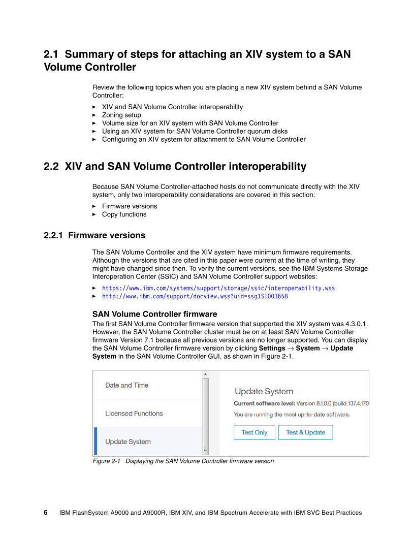
SAN Volume Controller firmwareThe first SAN Volume Controller firmware version that supported the XIV system was 4.3.0.1. However, the SAN Volume Controller cluster must be on at least SAN Volume Controller firmware Version 7.1 because all previous versions are no longer supported. You can display the SAN Volume Controller firmware version by clicking Settings → System → Update System in the SAN Volume Controller GUI, as shown in Figure 2-1.
Figure 2-1 Displaying the SAN Volume Controller firmware version
6 IBM FlashSystem A9000 and A9000R, IBM XIV, and IBM Spectrum Accelerate with IBM SVC Best Practices
Storwize V7000 firmwareThe Storwize V7000 system was first released with Version 6.1.x.x firmware. Because the Storwize V7000 firmware uses the same code base as the SAN Volume Controller, XIV support was inherited from the SAN Volume Controller code and is essentially the same. You can also run the lssystem command in the CLI to display the firmware version, as shown in Example 2-1. In this example, the Storwize V7000 system is at code level 7.7.0.4.
Example 2-1 Display the Storwize V7000 firmware version
IBM_Storwize:v7000-ctr-13:superuser>lssystem|grep codecode_level 7.7.0.4 (build 127.29.1609221137000)
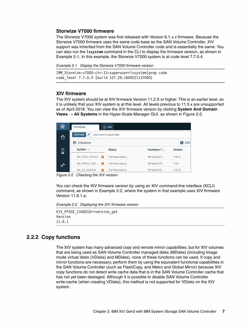
XIV firmwareThe XIV system should be at XIV firmware Version 11.2.X or higher. This is an earlier level, so it is unlikely that your XIV system is at this level. All levels previous to 11.5.x are unsupported as of April 2018. You can view the XIV firmware version by clicking System And Domain Views → All Systems in the Hyper-Scale Manager GUI, as shown in Figure 2-2.
Figure 2-2 Checking the XIV version
You can check the XIV firmware version by using an XIV command-line interface (XCLI) command, as shown in Example 2-2, where the system in that example uses XIV firmware Version 11.6.1.a.
Example 2-2 Displaying the XIV firmware version
XIV_PFE02_1340010>>version_getVersion 11.6.1
2.2.2 Copy functions
The XIV system has many advanced copy and remote mirror capabilities, but for XIV volumes that are being used as SAN Volume Controller managed disks (MDisks) (including Image mode virtual disks (VDisks) and MDisks), none of these functions can be used. If copy and mirror functions are necessary, perform them by using the equivalent functional capabilities in the SAN Volume Controller (such as FlashCopy, and Metro and Global Mirror) because XIV copy functions do not detect write cache data that is in the SAN Volume Controller cache that has not yet been destaged. Although it is possible to disable SAN Volume Controller write-cache (when creating VDisks), this method is not supported for VDisks on the XIV system.
Chapter 2. IBM XIV Gen3 with IBM System Storage SAN Volume Controller 7
2.3 Zoning setup
One of the first tasks of implementing an XIV system is to add it to the storage area network (SAN) fabric so that the SAN Volume Controller cluster can communicate with the XIV system over Fibre Channel (FC) technology. The XIV system can have up to 24 FC host ports. Each XIV system reports a single worldwide node name (WWNN) that is the same for every XIV FC host port. Each port also has a unique and persistent worldwide port name (WWPN). The preferred practice is to use ports 1 and 3 from each interface module, for a maximum of up to 12 ports total.
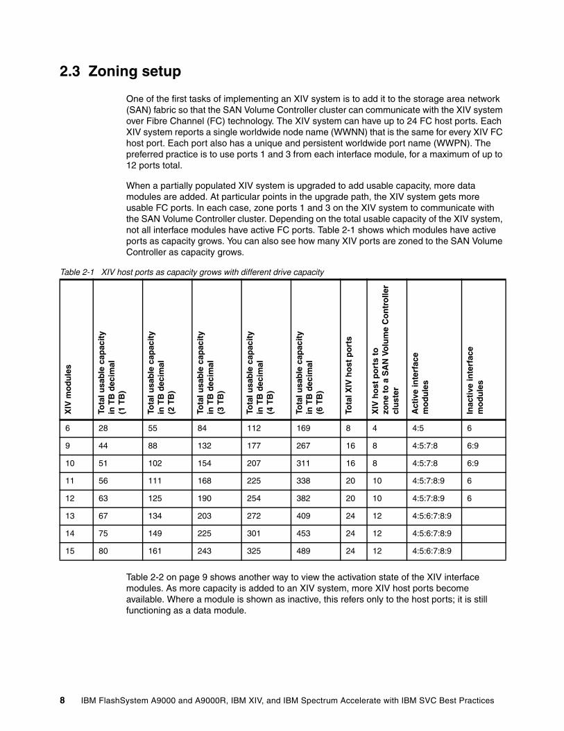
When a partially populated XIV system is upgraded to add usable capacity, more data modules are added. At particular points in the upgrade path, the XIV system gets more usable FC ports. In each case, zone ports 1 and 3 on the XIV system to communicate with the SAN Volume Controller cluster. Depending on the total usable capacity of the XIV system, not all interface modules have active FC ports. Table 2-1 shows which modules have active ports as capacity grows. You can also see how many XIV ports are zoned to the SAN Volume Controller as capacity grows.
Table 2-1 XIV host ports as capacity grows with different drive capacity
Table 2-2 on page 9 shows another way to view the activation state of the XIV interface modules. As more capacity is added to an XIV system, more XIV host ports become available. Where a module is shown as inactive, this refers only to the host ports; it is still functioning as a data module.
XIV
mo
du
les
Tota
l usa
ble
cap
acit
yin
TB
dec
imal
(1 T
B)
Tota
l usa
ble
cap
acit
yin
TB
dec
imal
(2 T
B)
Tota
l usa
ble
cap
acit
yin
TB
dec
imal
(3 T
B)
Tota
l usa
ble
cap
acit
yin
TB
dec
imal
(4 T
B)
Tota
l usa
ble
cap
acit
y in
TB
dec
imal
(6 T
B)
Tota
l XIV
ho
st p
ort
s
XIV
ho
st p
ort
s to
zo
ne
to a
SA
N V
olu
me
Co
ntr
olle
rcl
ust
er
Act
ive
inte
rfac
e m
od
ule
s
Inac
tive
inte
rfac
e m
od
ule
s
6 28 55 84 112 169 8 4 4:5 6
9 44 88 132 177 267 16 8 4:5:7:8 6:9
10 51 102 154 207 311 16 8 4:5:7:8 6:9
11 56 111 168 225 338 20 10 4:5:7:8:9 6
12 63 125 190 254 382 20 10 4:5:7:8:9 6
13 67 134 203 272 409 24 12 4:5:6:7:8:9
14 75 149 225 301 453 24 12 4:5:6:7:8:9
15 80 161 243 325 489 24 12 4:5:6:7:8:9
8 IBM FlashSystem A9000 and A9000R, IBM XIV, and IBM Spectrum Accelerate with IBM SVC Best Practices
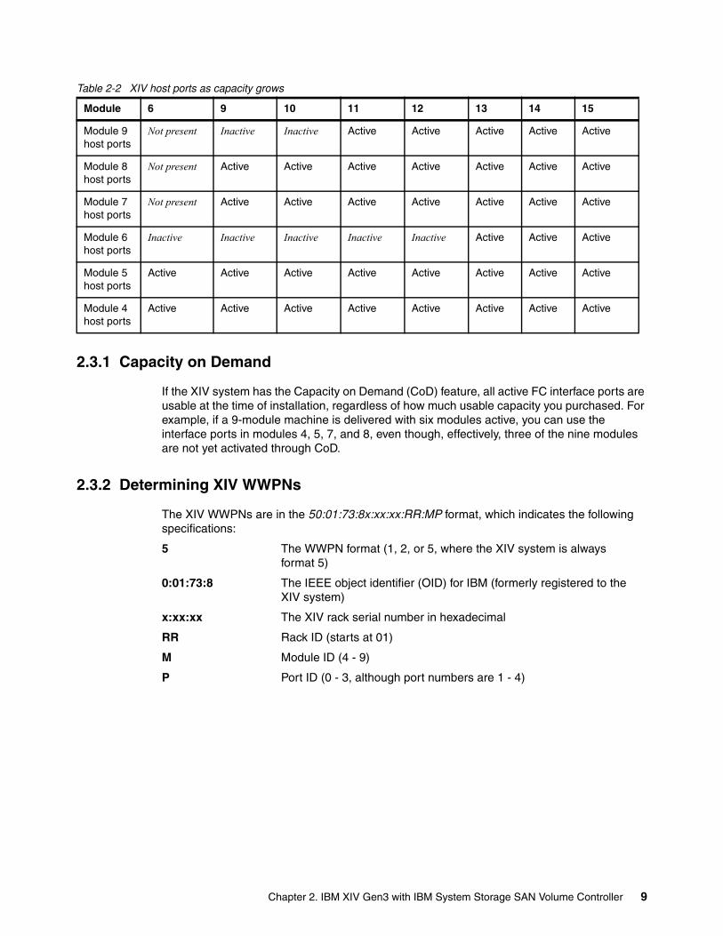
Table 2-2 XIV host ports as capacity grows
2.3.1 Capacity on Demand
If the XIV system has the Capacity on Demand (CoD) feature, all active FC interface ports are usable at the time of installation, regardless of how much usable capacity you purchased. For example, if a 9-module machine is delivered with six modules active, you can use the interface ports in modules 4, 5, 7, and 8, even though, effectively, three of the nine modules are not yet activated through CoD.
2.3.2 Determining XIV WWPNs
The XIV WWPNs are in the 50:01:73:8x:xx:xx:RR:MP format, which indicates the following specifications:
5 The WWPN format (1, 2, or 5, where the XIV system is always format 5)
0:01:73:8 The IEEE object identifier (OID) for IBM (formerly registered to the XIV system)
x:xx:xx The XIV rack serial number in hexadecimal
RR Rack ID (starts at 01)
M Module ID (4 - 9)
P Port ID (0 - 3, although port numbers are 1 - 4)
Module 6 9 10 11 12 13 14 15
Module 9host ports
Not present Inactive Inactive Active Active Active Active Active
Module 8host ports
Not present Active Active Active Active Active Active Active
Module 7host ports
Not present Active Active Active Active Active Active Active
Module 6host ports
Inactive Inactive Inactive Inactive Inactive Active Active Active
Module 5 host ports
Active Active Active Active Active Active Active Active
Module 4host ports
Active Active Active Active Active Active Active Active
Chapter 2. IBM XIV Gen3 with IBM System Storage SAN Volume Controller 9
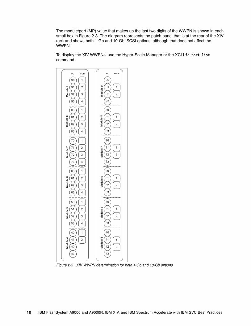
The module/port (MP) value that makes up the last two digits of the WWPN is shown in each small box in Figure 2-3. The diagram represents the patch panel that is at the rear of the XIV rack and shows both 1-Gb and 10-Gb iSCSI options, although that does not affect the WWPN.
To display the XIV WWPNs, use the Hyper-Scale Manager or the XCLI fc_port_list command.
Figure 2-3 XIV WWPN determination for both 1-Gb and 10-Gb options
10 IBM FlashSystem A9000 and A9000R, IBM XIV, and IBM Spectrum Accelerate with IBM SVC Best Practices
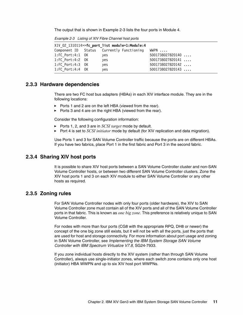
The output that is shown in Example 2-3 lists the four ports in Module 4.
Example 2-3 Listing of XIV Fibre Channel host ports
XIV_02_1310114>>fc_port_list module=1:Module:4Component ID Status Currently Functioning WWPN ....1:FC_Port:4:1 OK yes 5001738027820140 ....1:FC_Port:4:2 OK yes 5001738027820141 ....1:FC_Port:4:3 OK yes 5001738027820142 ....1:FC_Port:4:4 OK yes 5001738027820143 ....
2.3.3 Hardware dependencies
There are two FC host bus adapters (HBAs) in each XIV interface module. They are in the following locations:
� Ports 1 and 2 are on the left HBA (viewed from the rear).� Ports 3 and 4 are on the right HBA (viewed from the rear).
Consider the following configuration information:
� Ports 1, 2, and 3 are in SCSI target mode by default. � Port 4 is set to SCSI initiator mode by default (for XIV replication and data migration).
Use Ports 1 and 3 for SAN Volume Controller traffic because the ports are on different HBAs. If you have two fabrics, place Port 1 in the first fabric and Port 3 in the second fabric.
2.3.4 Sharing XIV host ports
It is possible to share XIV host ports between a SAN Volume Controller cluster and non-SAN Volume Controller hosts, or between two different SAN Volume Controller clusters. Zone the XIV host ports 1 and 3 on each XIV module to either SAN Volume Controller or any other hosts as required.
2.3.5 Zoning rules
For SAN Volume Controller nodes with only four ports (older hardware), the XIV to SAN Volume Controller zone must contain all of the XIV ports and all of the SAN Volume Controller ports in that fabric. This is known as one big zone. This preference is relatively unique to SAN Volume Controller.
For nodes with more than four ports (CG8 with the appropriate RPQ, DH8 or newer) the concept of the one big zone still exists, but it will not be with all the ports, just the ports that are used for host and storage connectivity. For more information about port usage and zoning in SAN Volume Controller, see Implementing the IBM System Storage SAN Volume Controller with IBM Spectrum Virtualize V7.8, SG24-7933.
If you zone individual hosts directly to the XIV system (rather than through SAN Volume Controller), always use single-initiator zones, where each switch zone contains only one host (initiator) HBA WWPN and up to six XIV host port WWPNs.
Chapter 2. IBM XIV Gen3 with IBM System Storage SAN Volume Controller 11
For SAN Volume Controller zoning, follow these rules:
� With current SAN Volume Controller firmware levels, do not zone more than 16 WWPNs from a single WWNN to a SAN Volume Controller cluster. Because the XIV system has only one WWNN, zone no more than 16 XIV host ports to a specific SAN Volume Controller cluster. If you use the suggestions in Table 2-1 on page 8, this restriction is not a concern.
� All nodes in a SAN Volume Controller cluster must be able to see the same set of XIV host ports. Operation in a mode where two nodes see a different set of host ports on the same XIV system results in the controller showing as degraded on the SAN Volume Controller, so the system error log requests a repair.
2.4 Volume size for an XIV system with SAN Volume Controller
There are several considerations when you are attaching an XIV system to a SAN Volume Controller. Volume size is an important one. The optimum volume size depends on the maximum SCSI queue depth of the SAN Volume Controller MDisks. Another important consideration is whether the XIV system has compression enabled.
If compression is enabled in the XIV, the host that is attached to SAN Volume Controller, and SAN Volume Controller itself, do not really know what compression ratio is occurring, so it is important to make a few changes to the volume creation process.
When using a thin pool, whether compressed or not, do not assign all of the XIV hard capacity to the pool for the SAN Volume Controller disks. The default behavior for the XIV system is to have all the volumes in a pool go read-only when hard capacity is depleted. This behavior might result in a data access event. If some hard capacity is left in reserve, it can be added to the pool if capacity is depleted, enabling migration of data from the XIV system to some other storage. A small percent, about 5% of the total hard space that is allocated to the pool, is sufficient. A smaller percentage is acceptable, but careful monitoring of the capacity of the XIV system is required.
While the XIV system is compressing the volumes, you must estimate the compression ratio to know how many volumes must be created. If possible, run the compression estimation tool, or compresstimator, to get an estimate. If that is not possible, assume a 2:1 compression ratio. Whatever the compression ratio is, multiply that number times the number of volumes.
As an example, looking at Table 2-3 on page 14, for 6 TB drives, the minimum preferred volume size is 9701, with 50 volumes. Assuming the compression ratio is 2.5:1, multiply 50 by 2.5 to get 125 volumes. If it turns out the compression ratio is better, you can always create more volumes, add them to the pool, and SAN Volume Controller then rebalances across them.
2.4.1 SCSI queue depth considerations
Before firmware Version 6.3, the SAN Volume Controller used one XIV host port as a preferred path for each MDisk (assigning them in a round-robin fashion). Therefore, the preferred practice is to configure sufficient volumes on the XIV system to ensure that the following situations are met:
� Each XIV host port receives closely matching I/O levels.� The SAN Volume Controller uses the deep queue depth of each XIV host port.
12 IBM FlashSystem A9000 and A9000R, IBM XIV, and IBM Spectrum Accelerate with IBM SVC Best Practices
Ideally, the number of MDisks that is presented by the XIV system to the SAN Volume Controller is a multiple of the number of XIV host ports, 1 - 4.
Because Version 6.3 SAN Volume Controller introduced round-robin for each MDisk, it is no longer necessary to balance the load manually. But, it is still necessary to have several MDisks because of the queue depth limitation of SAN Volume Controller.
The XIV system can handle a queue depth of 1400 per FC host port and a queue depth of 256 per mapped volume per host port:target port:volume tuple. However, the SAN Volume Controller sets the following internal limits:
� The maximum queue depth per MDisk is 60.� The maximum queue depth per target host port on an XIV system is 1000.
Based on this knowledge, you can determine an ideal number of XIV volumes to map to the SAN Volume Controller for use as MDisks by using the following equation:
Q = ((P x C) / N) / M
The equation has the following components:
Q Calculated queue depth for each MDisk
P Number of XIV host ports (unique WWPNs) that are visible to the SAN Volume Controller cluster (use 4, 8, 10, or 12, depending on the number of modules in the XIV system)
N Number of nodes in the SAN Volume Controller cluster (2, 4, 6, or 8)
M Number of volumes that are presented by the XIV system to the SAN Volume Controller cluster (detected as MDisks)
C 1000 (the maximum SCSI queue depth that a SAN Volume Controller uses for each XIV host port)
If a 2-node SAN Volume Controller cluster is being used with four ports on an XIV system and 16 MDisks, the equation yields the following queue depth:
Q = ((4 ports*1000)/2 nodes)/16 MDisks = 125
Because 125 is more than 60, the SAN Volume Controller uses a queue depth of 60 per MDisk.
If a 4-node SAN Volume Controller cluster is being used with 12 host ports on the XIV system and 50 MDisks, the equation yields the following queue depth:
Q = ((12 ports*1000)/4 nodes)/50 MDisks = 60
Because of the high value that is allowed per MDisk, and the fact that the preferred practice for the IBM Spectrum Accelerate family is to create a smaller number of larger volumes, it is unusual for a configuration to exceed the maximum queue depth. However, care must be taken to not create so many volumes that the queue depth per MDisk becomes too small. Numbers less than 35 - 40 per MDisk should be reviewed carefully, as there might be performance implications.
Chapter 2. IBM XIV Gen3 with IBM System Storage SAN Volume Controller 13
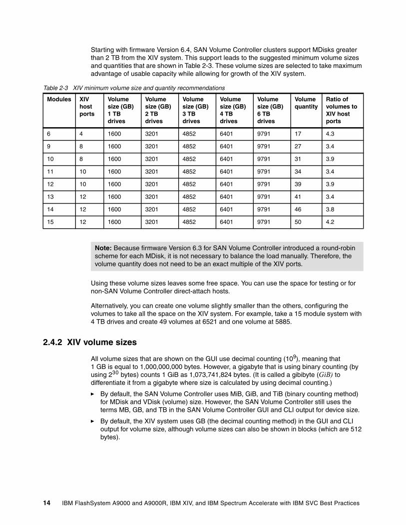
Starting with firmware Version 6.4, SAN Volume Controller clusters support MDisks greater than 2 TB from the XIV system. This support leads to the suggested minimum volume sizes and quantities that are shown in Table 2-3. These volume sizes are selected to take maximum advantage of usable capacity while allowing for growth of the XIV system.
Table 2-3 XIV minimum volume size and quantity recommendations
Using these volume sizes leaves some free space. You can use the space for testing or for non-SAN Volume Controller direct-attach hosts.
Alternatively, you can create one volume slightly smaller than the others, configuring the volumes to take all the space on the XIV system. For example, take a 15 module system with 4 TB drives and create 49 volumes at 6521 and one volume at 5885.
2.4.2 XIV volume sizes
All volume sizes that are shown on the GUI use decimal counting (109), meaning that 1 GB is equal to 1,000,000,000 bytes. However, a gigabyte that is using binary counting (by using 230 bytes) counts 1 GiB as 1,073,741,824 bytes. (It is called a gibibyte (GiB) to differentiate it from a gigabyte where size is calculated by using decimal counting.)
� By default, the SAN Volume Controller uses MiB, GiB, and TiB (binary counting method) for MDisk and VDisk (volume) size. However, the SAN Volume Controller still uses the terms MB, GB, and TB in the SAN Volume Controller GUI and CLI output for device size.
� By default, the XIV system uses GB (the decimal counting method) in the GUI and CLI output for volume size, although volume sizes can also be shown in blocks (which are 512 bytes).
Modules XIV host ports
Volume size (GB)1 TB drives
Volume size (GB)2 TB drives
Volume size (GB)3 TB drives
Volume size (GB)4 TB drives
Volume size (GB)6 TB drives
Volume quantity
Ratio of volumes to XIV host ports
6 4 1600 3201 4852 6401 9791 17 4.3
9 8 1600 3201 4852 6401 9791 27 3.4
10 8 1600 3201 4852 6401 9791 31 3.9
11 10 1600 3201 4852 6401 9791 34 3.4
12 10 1600 3201 4852 6401 9791 39 3.9
13 12 1600 3201 4852 6401 9791 41 3.4
14 12 1600 3201 4852 6401 9791 46 3.8
15 12 1600 3201 4852 6401 9791 50 4.2
Note: Because firmware Version 6.3 for SAN Volume Controller introduced a round-robin scheme for each MDisk, it is not necessary to balance the load manually. Therefore, the volume quantity does not need to be an exact multiple of the XIV ports.
14 IBM FlashSystem A9000 and A9000R, IBM XIV, and IBM Spectrum Accelerate with IBM SVC Best Practices
It is important to understand that a volume that is created on an XIV system is created in roughly 17-GB increments. The exact size of the allocation unit is 16411 1 MiB partitions. The size of an XIV 17-GB volume can be described in four ways:
GB Decimal sizing where 1 GB is 1,000,000,000 bytes
GiB Binary counting where 1 GiB = 230 bytes or 1,073,741,824 bytes
Bytes Number of bytes
Blocks Blocks that are 512 bytes
Table 2-4 shows how these values are used in the XIV system.
Table 2-4 XIV space allocation in units
Therefore, the XIV system is using binary sizing when creating volumes, but displaying it in decimals and then rounding it down.
The suggested size for XIV volumes that are presented to the SAN Volume Controller for 2 TB drives, where only 1 TB is used, is 1600 GB on the XIV system. Although there is nothing special about this volume size, it divides nicely to create, on average, 4 - 8 XIV volumes per XIV host port (for queue depth).
Table 2-5 lists suggested volume sizes.
Table 2-5 Suggested volume sizes on the XIV system for 2 TB drives that are presented to SAN Volume Controller
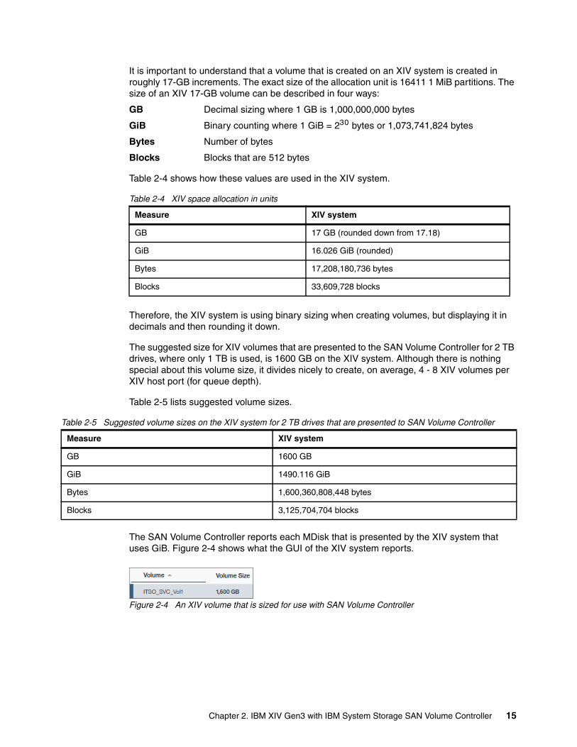
The SAN Volume Controller reports each MDisk that is presented by the XIV system that uses GiB. Figure 2-4 shows what the GUI of the XIV system reports.
Figure 2-4 An XIV volume that is sized for use with SAN Volume Controller
Measure XIV system
GB 17 GB (rounded down from 17.18)
GiB 16.026 GiB (rounded)
Bytes 17,208,180,736 bytes
Blocks 33,609,728 blocks
Measure XIV system
GB 1600 GB
GiB 1490.116 GiB
Bytes 1,600,360,808,448 bytes
Blocks 3,125,704,704 blocks
Chapter 2. IBM XIV Gen3 with IBM System Storage SAN Volume Controller 15
This volume is 3,125,704,704 blocks in size. If you multiply 3,125,704,704 by 512 (because there are 512 bytes in a SCSI block), you get 1,600,360,808,448 bytes. That is exactly what the SAN Volume Controller reports for the same volume (MDisk), as shown in Example 2-4.
Example 2-4 XIV MDisk
IBM_2145:SVC-0708:superuser>lsmdisk -bytesid name status mode mdisk_grp_id mdisk_grp_name capacity ....0 mdisk0 online unmanaged 1600360808448 ....
2.4.3 Creating XIV volumes with the same size as SAN Volume Controller VDisks
To create an XIV volume that is the same size as an existing SAN Volume Controller VDisk, you can use the process that is documented in “Creating a volume that is the same size” on page 76. This is only for a transition to or from Image mode.
2.4.4 Creating managed disk groups
All volumes that are presented by the XIV system to the SAN Volume Controller are represented as MDisks, which are then grouped into one or more MDisk groups or pools. Your decision is how many MDisk groups to use.
If you are virtualizing multiple XIV systems (or other storage devices) behind a SAN Volume Controller, create at least one MDisk group for each additional storage device. Except for solid-state drive (SSD)-based MDisks that are used for Easy Tier, do not have MDisks from different storage devices in a common MDisk group.
In general, create only one MDisk group for each XIV system because that is the simplest and most effective way to configure your storage. However, if you have many MDisk groups, you must understand the way that the SAN Volume Controller partitions cache data when they accept write I/O. Because the SAN Volume Controller can virtualize storage from many storage devices, you might encounter an issue if there are slow-draining storage controllers, which occurs if write data enters the SAN Volume Controller cache faster than the SAN Volume Controller can destage write data to the back-end disk.
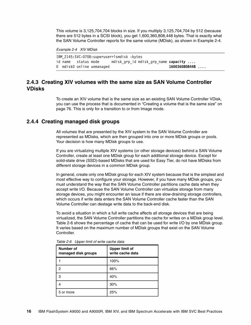
To avoid a situation in which a full write cache affects all storage devices that are being virtualized, the SAN Volume Controller partitions the cache for writes on a MDisk group level. Table 2-6 shows the percentage of cache that can be used for write I/O by one MDisk group. It varies based on the maximum number of MDisk groups that exist on the SAN Volume Controller.
Table 2-6 Upper limit of write cache data
Number of managed disk groups
Upper limit of write cache data
1 100%
2 66%
3 40%
4 30%
5 or more 25%
16 IBM FlashSystem A9000 and A9000R, IBM XIV, and IBM Spectrum Accelerate with IBM SVC Best Practices
For example, assume that three MDisk groups exist on a SAN Volume Controller, where two of them represent slow-draining, older storage devices and the third is used by an XIV system. The result is that the XIV system can be restricted to 40% of the SAN Volume Controller cache for write I/O, which might become an issue during periods of high write I/O. The solution in that case might be to have multiple MDisk groups for a single XIV system. For more information, see IBM System Storage SAN Volume Controller and Storwize V7000 Best Practices and Performance Guidelines, SG24-7521.
2.4.5 SAN Volume Controller MDisk group extent sizes
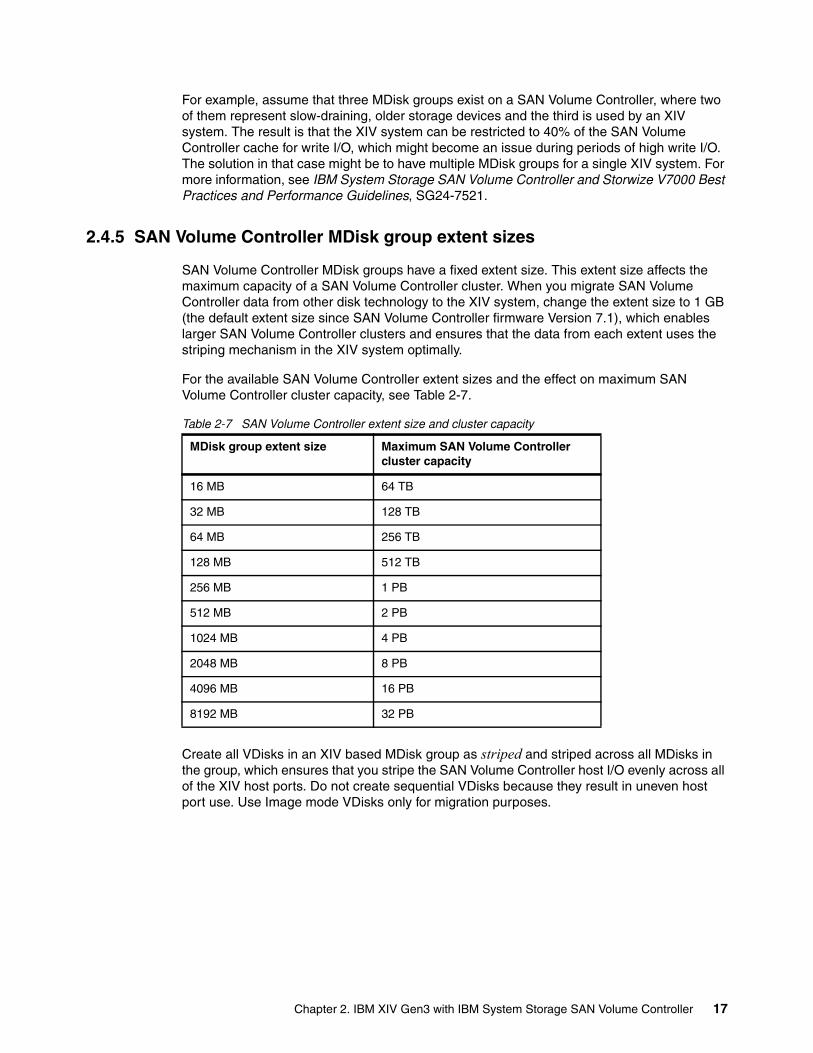
SAN Volume Controller MDisk groups have a fixed extent size. This extent size affects the maximum capacity of a SAN Volume Controller cluster. When you migrate SAN Volume Controller data from other disk technology to the XIV system, change the extent size to 1 GB (the default extent size since SAN Volume Controller firmware Version 7.1), which enables larger SAN Volume Controller clusters and ensures that the data from each extent uses the striping mechanism in the XIV system optimally.
For the available SAN Volume Controller extent sizes and the effect on maximum SAN Volume Controller cluster capacity, see Table 2-7.
Table 2-7 SAN Volume Controller extent size and cluster capacity
Create all VDisks in an XIV based MDisk group as striped and striped across all MDisks in the group, which ensures that you stripe the SAN Volume Controller host I/O evenly across all of the XIV host ports. Do not create sequential VDisks because they result in uneven host port use. Use Image mode VDisks only for migration purposes.
MDisk group extent size Maximum SAN Volume Controller cluster capacity
16 MB 64 TB
32 MB 128 TB
64 MB 256 TB
128 MB 512 TB
256 MB 1 PB
512 MB 2 PB
1024 MB 4 PB
2048 MB 8 PB
4096 MB 16 PB
8192 MB 32 PB
Chapter 2. IBM XIV Gen3 with IBM System Storage SAN Volume Controller 17
2.5 Using an XIV system for SAN Volume Controller quorum disks
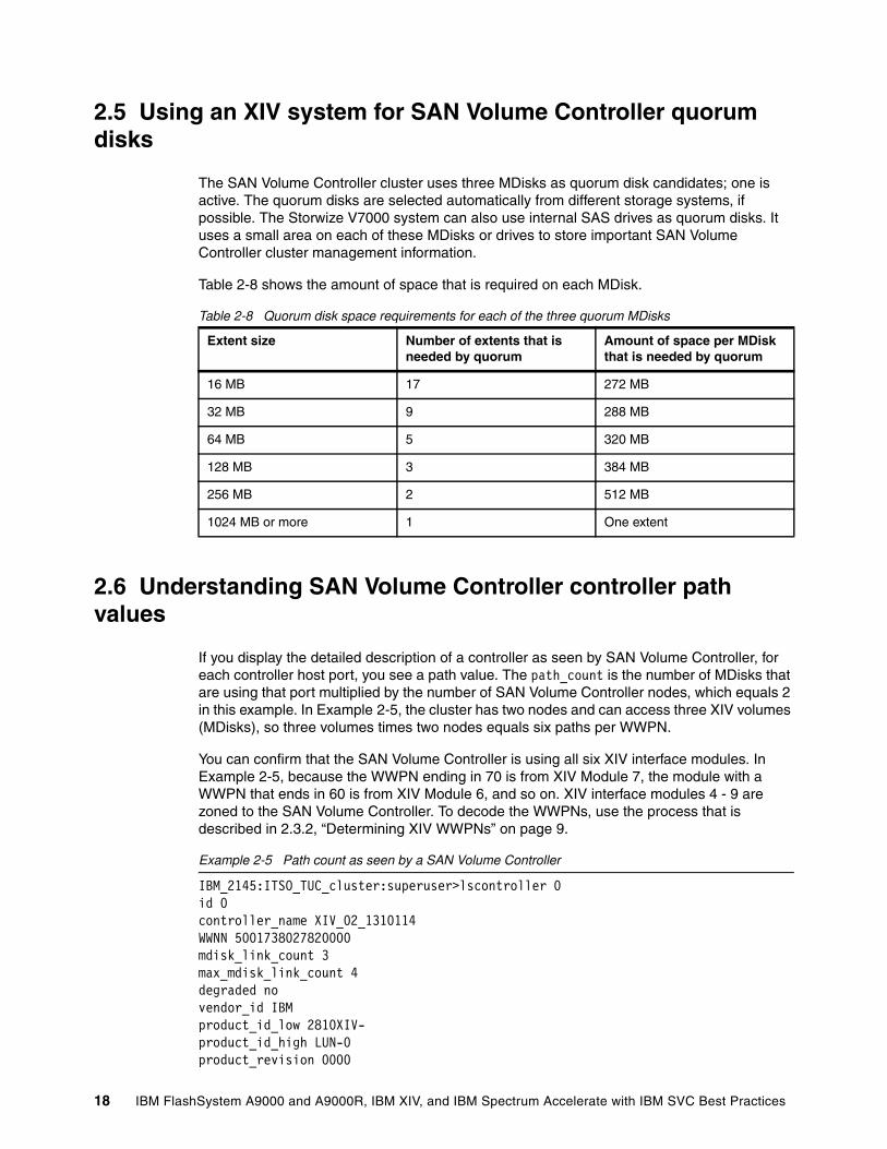
The SAN Volume Controller cluster uses three MDisks as quorum disk candidates; one is active. The quorum disks are selected automatically from different storage systems, if possible. The Storwize V7000 system can also use internal SAS drives as quorum disks. It uses a small area on each of these MDisks or drives to store important SAN Volume Controller cluster management information.
Table 2-8 shows the amount of space that is required on each MDisk.
Table 2-8 Quorum disk space requirements for each of the three quorum MDisks
2.6 Understanding SAN Volume Controller controller path values
If you display the detailed description of a controller as seen by SAN Volume Controller, for each controller host port, you see a path value. The path_count is the number of MDisks that are using that port multiplied by the number of SAN Volume Controller nodes, which equals 2 in this example. In Example 2-5, the cluster has two nodes and can access three XIV volumes (MDisks), so three volumes times two nodes equals six paths per WWPN.
You can confirm that the SAN Volume Controller is using all six XIV interface modules. In Example 2-5, because the WWPN ending in 70 is from XIV Module 7, the module with a WWPN that ends in 60 is from XIV Module 6, and so on. XIV interface modules 4 - 9 are zoned to the SAN Volume Controller. To decode the WWPNs, use the process that is described in 2.3.2, “Determining XIV WWPNs” on page 9.
Example 2-5 Path count as seen by a SAN Volume Controller
IBM_2145:ITSO_TUC_cluster:superuser>lscontroller 0id 0controller_name XIV_02_1310114WWNN 5001738027820000mdisk_link_count 3max_mdisk_link_count 4degraded novendor_id IBMproduct_id_low 2810XIV-product_id_high LUN-0product_revision 0000
Extent size Number of extents that is needed by quorum
Amount of space per MDisk that is needed by quorum
16 MB 17 272 MB
32 MB 9 288 MB
64 MB 5 320 MB
128 MB 3 384 MB
256 MB 2 512 MB
1024 MB or more 1 One extent
18 IBM FlashSystem A9000 and A9000R, IBM XIV, and IBM Spectrum Accelerate with IBM SVC Best Practices
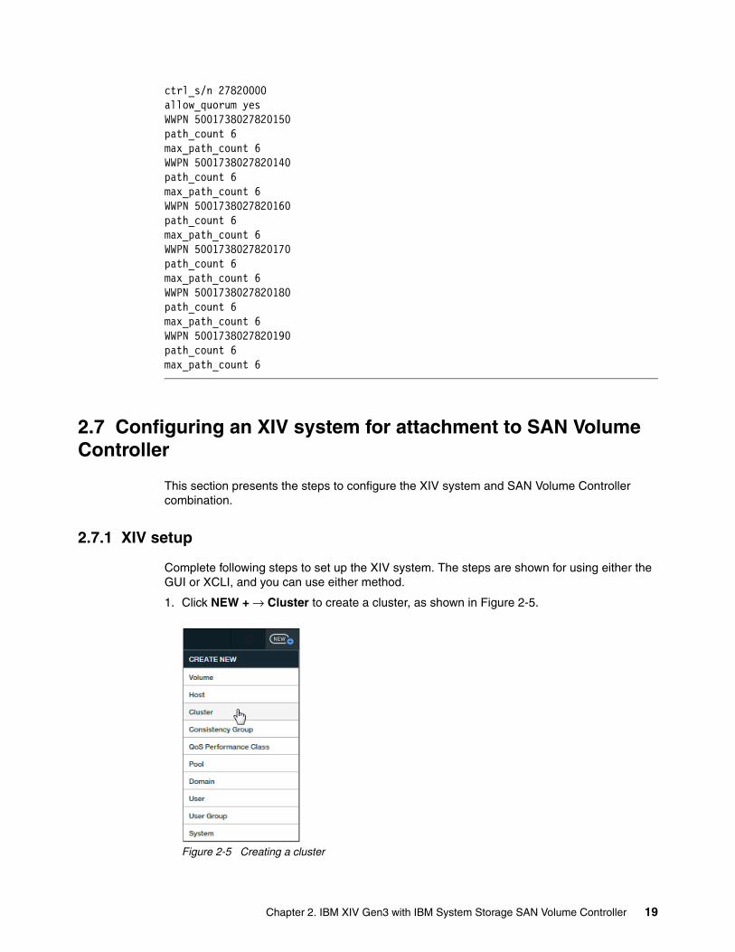
ctrl_s/n 27820000allow_quorum yesWWPN 5001738027820150path_count 6max_path_count 6WWPN 5001738027820140path_count 6max_path_count 6WWPN 5001738027820160path_count 6max_path_count 6WWPN 5001738027820170path_count 6max_path_count 6WWPN 5001738027820180path_count 6max_path_count 6WWPN 5001738027820190path_count 6max_path_count 6
2.7 Configuring an XIV system for attachment to SAN Volume Controller
This section presents the steps to configure the XIV system and SAN Volume Controller combination.
2.7.1 XIV setup
Complete following steps to set up the XIV system. The steps are shown for using either the GUI or XCLI, and you can use either method.
1. Click NEW + → Cluster to create a cluster, as shown in Figure 2-5.
Figure 2-5 Creating a cluster
Chapter 2. IBM XIV Gen3 with IBM System Storage SAN Volume Controller 19
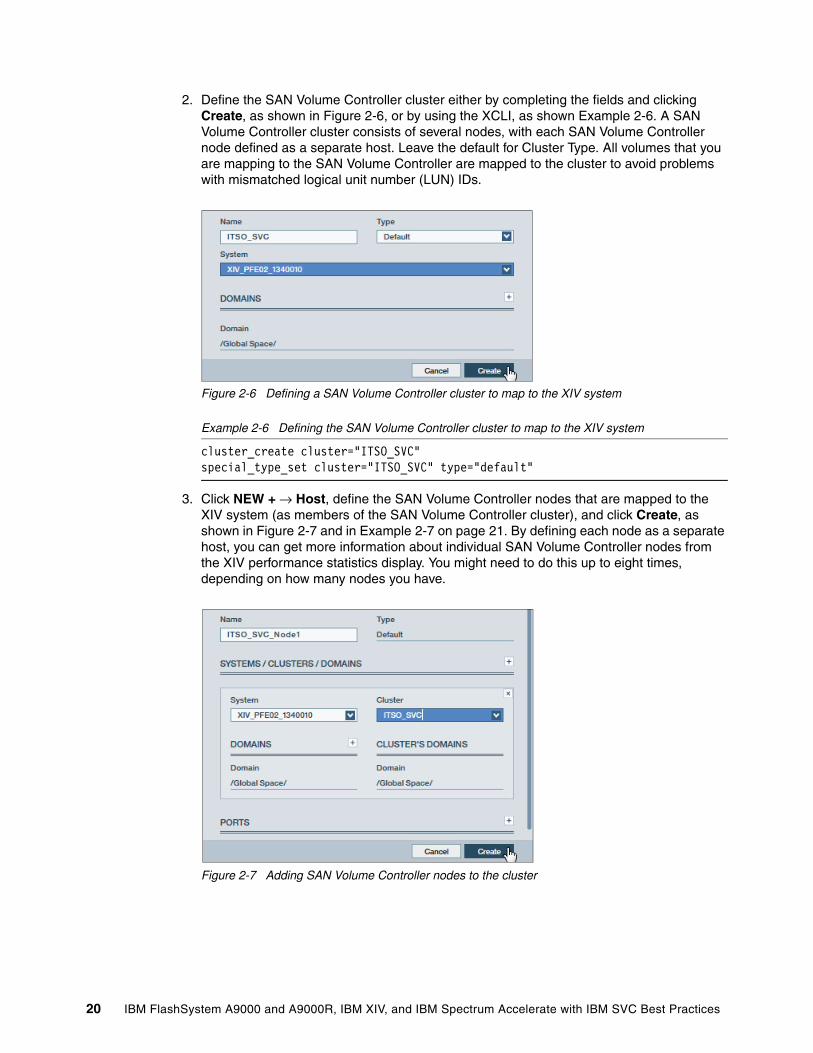
2. Define the SAN Volume Controller cluster either by completing the fields and clicking Create, as shown in Figure 2-6, or by using the XCLI, as shown Example 2-6. A SAN Volume Controller cluster consists of several nodes, with each SAN Volume Controller node defined as a separate host. Leave the default for Cluster Type. All volumes that you are mapping to the SAN Volume Controller are mapped to the cluster to avoid problems with mismatched logical unit number (LUN) IDs.
Figure 2-6 Defining a SAN Volume Controller cluster to map to the XIV system
Example 2-6 Defining the SAN Volume Controller cluster to map to the XIV system
cluster_create cluster="ITSO_SVC"special_type_set cluster="ITSO_SVC" type="default"
3. Click NEW + → Host, define the SAN Volume Controller nodes that are mapped to the XIV system (as members of the SAN Volume Controller cluster), and click Create, as shown in Figure 2-7 and in Example 2-7 on page 21. By defining each node as a separate host, you can get more information about individual SAN Volume Controller nodes from the XIV performance statistics display. You might need to do this up to eight times, depending on how many nodes you have.
Figure 2-7 Adding SAN Volume Controller nodes to the cluster
20 IBM FlashSystem A9000 and A9000R, IBM XIV, and IBM Spectrum Accelerate with IBM SVC Best Practices
Example 2-7 Defining the SAN Volume Controller nodes that are mapped to the XIV system
host_define host="ITSO_SVC_Node1" cluster="ITSO_SVC"host_define host="ITSO_SVC_Node2" cluster="ITSO_SVC"
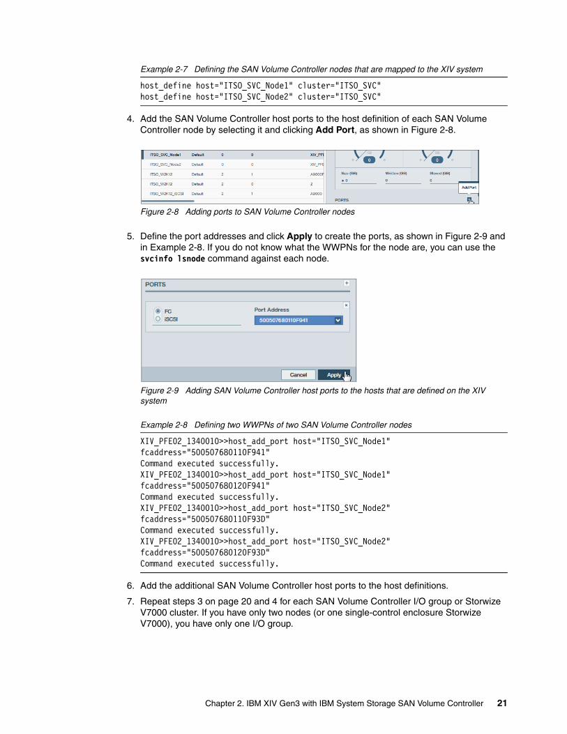
4. Add the SAN Volume Controller host ports to the host definition of each SAN Volume Controller node by selecting it and clicking Add Port, as shown in Figure 2-8.
Figure 2-8 Adding ports to SAN Volume Controller nodes
5. Define the port addresses and click Apply to create the ports, as shown in Figure 2-9 and in Example 2-8. If you do not know what the WWPNs for the node are, you can use the svcinfo lsnode command against each node.
Figure 2-9 Adding SAN Volume Controller host ports to the hosts that are defined on the XIV system
Example 2-8 Defining two WWPNs of two SAN Volume Controller nodes
XIV_PFE02_1340010>>host_add_port host="ITSO_SVC_Node1" fcaddress="500507680110F941"Command executed successfully.XIV_PFE02_1340010>>host_add_port host="ITSO_SVC_Node1" fcaddress="500507680120F941"Command executed successfully.XIV_PFE02_1340010>>host_add_port host="ITSO_SVC_Node2" fcaddress="500507680110F93D"Command executed successfully.XIV_PFE02_1340010>>host_add_port host="ITSO_SVC_Node2" fcaddress="500507680120F93D"Command executed successfully.
6. Add the additional SAN Volume Controller host ports to the host definitions.
7. Repeat steps 3 on page 20 and 4 for each SAN Volume Controller I/O group or Storwize V7000 cluster. If you have only two nodes (or one single-control enclosure Storwize V7000), you have only one I/O group.
Chapter 2. IBM XIV Gen3 with IBM System Storage SAN Volume Controller 21
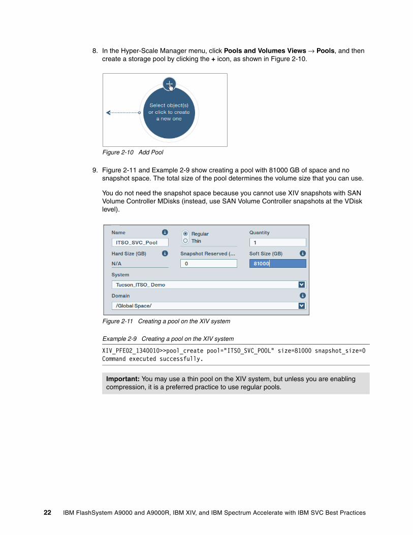
8. In the Hyper-Scale Manager menu, click Pools and Volumes Views → Pools, and then create a storage pool by clicking the + icon, as shown in Figure 2-10.
Figure 2-10 Add Pool
9. Figure 2-11 and Example 2-9 show creating a pool with 81000 GB of space and no snapshot space. The total size of the pool determines the volume size that you can use.
You do not need the snapshot space because you cannot use XIV snapshots with SAN Volume Controller MDisks (instead, use SAN Volume Controller snapshots at the VDisk level).
Figure 2-11 Creating a pool on the XIV system
Example 2-9 Creating a pool on the XIV system
XIV_PFE02_1340010>>pool_create pool="ITSO_SVC_POOL" size=81000 snapshot_size=0Command executed successfully.
Important: You may use a thin pool on the XIV system, but unless you are enabling compression, it is a preferred practice to use regular pools.
22 IBM FlashSystem A9000 and A9000R, IBM XIV, and IBM Spectrum Accelerate with IBM SVC Best Practices

10.Create the volumes in the pool on the XIV system by clicking New + → Volumes, complete all the necessary values, and click Create to create the volumes, as shown in Figure 2-12 and in Example 2-10.
Figure 2-12 Adding XIV volumes
Example 2-10 Commands to create XIV volumes for use by the SAN Volume Controller
XIV_PFE02_1340010>>vol_create size=3200 pool="ITSO_SVC_POOL" vol="ITSO_SVC_VOL_001"Command executed successfully.XIV_PFE02_1340010>>vol_create size=3200 pool="ITSO_SVC_POOL" vol="ITSO_SVC_VOL_002"Command executed successfully.XIV_PFE02_1340010>>vol_create size=3200 pool="ITSO_SVC_POOL" vol="ITSO_SVC_VOL_003"Command executed successfully.
11.Select the volumes, and click Actions → Mapping → View/Modify Mapping, as shown in Figure 2-13.
Figure 2-13 Selecting volumes to map
Chapter 2. IBM XIV Gen3 with IBM System Storage SAN Volume Controller 23

12.Select Cluster and click the + icon to map the volumes. Select the SAN Volume Controller cluster to map the volumes, as shown in Figure 2-14 and Example 2-11.
Figure 2-14 Mapping XIV volumes to the SAN Volume Controller
Example 2-11 Commands to map XIV volumes to the SAN Volume Controller cluster
XIV_PFE02_1340010>>map_vol cluster="ITSO_SVC" override=yes vol="ITSO_SVC_VOL_001" lun="1"Command executed successfully.XIV_PFE02_1340010>>map_vol cluster="ITSO_SVC" override=yes vol="ITSO_SVC_VOL_002" lun="2"Command executed successfully.XIV_PFE02_1340010>>map_vol cluster="ITSO_SVC" override=yes vol="ITSO_SVC_VOL_003" lun="3"Command executed successfully.
2.7.2 SAN Volume Controller setup steps
Assuming that the SAN Volume Controller is zoned to the XIV system, switch to the SAN Volume Controller and complete the following steps:
1. Detect the XIV volumes either by using the svctask detectmdisk CLI command, or use the SAN Volume Controller GUI that is shown in Figure 2-15 and click Pools → External Storage → Actions → Discover Storage.
Figure 2-15 Detecting MDisks by using the SAN Volume Controller GUI
2. List the newly detected MDisks, shown in Figure 2-16 on page 25 and Example 2-12 on page 25, where there are three free MDisks. They are 2.91 TiB (3201 GB).
Important: All volumes must be mapped with the same LUN ID to all nodes of a SAN Volume Controller cluster. Therefore, map the volumes to the cluster, not to individual nodes of the cluster.
Tip: The XIV system normally reserves LUN ID 0 for in-band management. The SAN Volume Controller cannot take advantage of this ID, but there is no adverse effect.
24 IBM FlashSystem A9000 and A9000R, IBM XIV, and IBM Spectrum Accelerate with IBM SVC Best Practices
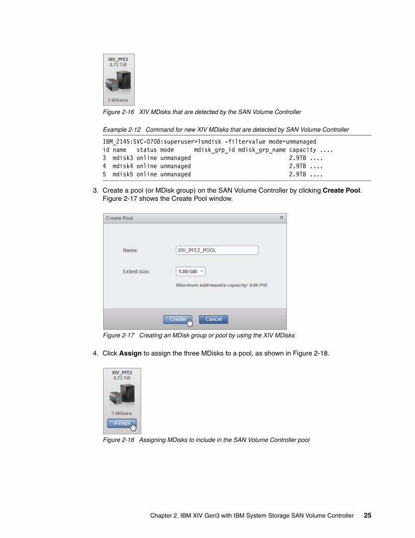
Figure 2-16 XIV MDisks that are detected by the SAN Volume Controller
Example 2-12 Command for new XIV MDisks that are detected by SAN Volume Controller
IBM_2145:SVC-0708:superuser>lsmdisk -filtervalue mode=unmanagedid name status mode mdisk_grp_id mdisk_grp_name capacity ....3 mdisk3 online unmanaged 2.9TB ....4 mdisk4 online unmanaged 2.9TB ....5 mdisk5 online unmanaged 2.9TB ....
3. Create a pool (or MDisk group) on the SAN Volume Controller by clicking Create Pool. Figure 2-17 shows the Create Pool window.
Figure 2-17 Creating an MDisk group or pool by using the XIV MDisks
4. Click Assign to assign the three MDisks to a pool, as shown in Figure 2-18.
Figure 2-18 Assigning MDisks to include in the SAN Volume Controller pool
Chapter 2. IBM XIV Gen3 with IBM System Storage SAN Volume Controller 25
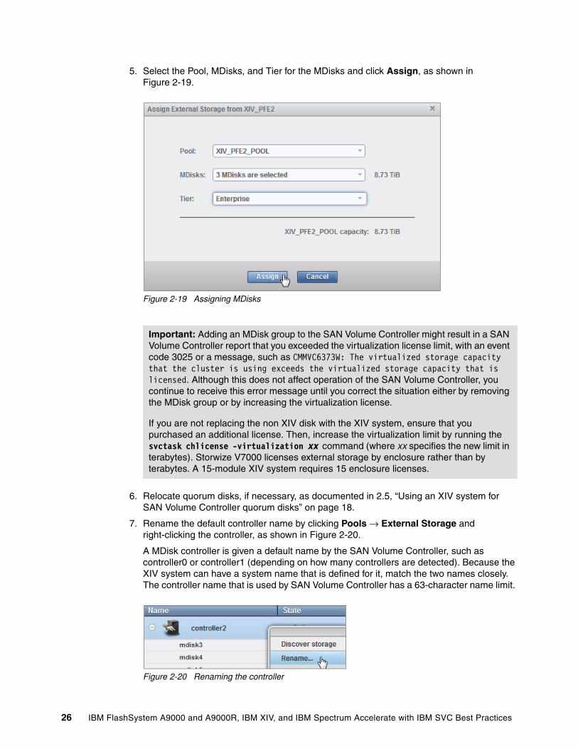
5. Select the Pool, MDisks, and Tier for the MDisks and click Assign, as shown in Figure 2-19.
Figure 2-19 Assigning MDisks
6. Relocate quorum disks, if necessary, as documented in 2.5, “Using an XIV system for SAN Volume Controller quorum disks” on page 18.
7. Rename the default controller name by clicking Pools → External Storage and right-clicking the controller, as shown in Figure 2-20.
A MDisk controller is given a default name by the SAN Volume Controller, such as controller0 or controller1 (depending on how many controllers are detected). Because the XIV system can have a system name that is defined for it, match the two names closely. The controller name that is used by SAN Volume Controller has a 63-character name limit.
Figure 2-20 Renaming the controller
Important: Adding an MDisk group to the SAN Volume Controller might result in a SAN Volume Controller report that you exceeded the virtualization license limit, with an event code 3025 or a message, such as CMMVC6373W: The virtualized storage capacity that the cluster is using exceeds the virtualized storage capacity that is licensed. Although this does not affect operation of the SAN Volume Controller, you continue to receive this error message until you correct the situation either by removing the MDisk group or by increasing the virtualization license.
If you are not replacing the non XIV disk with the XIV system, ensure that you purchased an additional license. Then, increase the virtualization limit by running the svctask chlicense -virtualization xx command (where xx specifies the new limit in terabytes). Storwize V7000 licenses external storage by enclosure rather than by terabytes. A 15-module XIV system requires 15 enclosure licenses.
26 IBM FlashSystem A9000 and A9000R, IBM XIV, and IBM Spectrum Accelerate with IBM SVC Best Practices

Now you can follow one of the migration strategies that are described in Chapter 5, “Data movement concepts: SAN Volume Controller and the IBM Spectrum Accelerate family” on page 63.
Chapter 2. IBM XIV Gen3 with IBM System Storage SAN Volume Controller 27

28 IBM FlashSystem A9000 and A9000R, IBM XIV, and IBM Spectrum Accelerate with IBM SVC Best Practices
Chapter 3. IBM FlashSystem A9000 or IBM FlashSystem A9000R with SAN Volume Controller
The sections that follow address each of the requirements of an implementation plan in the order in which they arise. However, this chapter does not cover physical implementation requirements (such as power requirements) because they are already addressed in IBM FlashSystem A9000 and IBM FlashSystem A9000R Architecture and Implementation, SG24-8345.
3
© Copyright IBM Corp. 2016, 2018. All rights reserved. 29
3.1 Summary of steps
Review the following topics when you are placing a new IBM FlashSystem A9000 or IBM FlashSystem A9000R system behind a SAN Volume Controller:
� IBM FlashSystem A9000 or IBM FlashSystem A9000R and SAN Volume Controller interoperability
� Zoning considerations
� Volume size for IBM FlashSystem A9000 or IBM FlashSystem A9000R with SAN Volume Controller
� SAN Volume Controller controller path values
� Configuring IBM FlashSystem A9000 or IBM FlashSystem A9000R for SAN Volume Controller attachment
3.2 IBM FlashSystem A9000 or IBM FlashSystem A9000R and SAN Volume Controller interoperability
SAN Volume Controller-attached hosts do not communicate directly with the storage system, and copy functions are performed at the SAN Volume Controller level.
3.2.1 Firmware versions
SAN Volume Controller, IBM FlashSystem A9000, and IBM FlashSystem A9000R systems have minimum firmware requirements. Although the versions that are cited in this paper were current at the time of writing, they might have changed since then. To verify the current versions, see the IBM Systems Storage Interoperation Center (SSIC) and SAN Volume Controller support websites:
� https://www-03.ibm.com/systems/support/storage/ssic/interoperability.wss � http://www.ibm.com/support/docview.wss?uid=ssg1S1003658
SAN Volume Controller firmwareTable 3-1 shows the minimum SAN Volume Controller firmware that is required to support IBM FlashSystem A9000 or IBM FlashSystem A9000R systems.
Table 3-1 SAN Volume Controller firmware levels
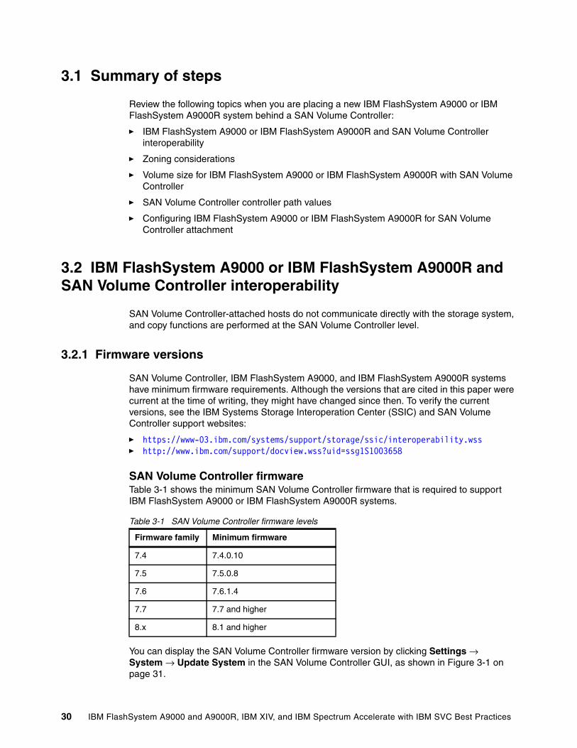
You can display the SAN Volume Controller firmware version by clicking Settings → System → Update System in the SAN Volume Controller GUI, as shown in Figure 3-1 on page 31.
Firmware family Minimum firmware
7.4 7.4.0.10
7.5 7.5.0.8
7.6 7.6.1.4
7.7 7.7 and higher
8.x 8.1 and higher
30 IBM FlashSystem A9000 and A9000R, IBM XIV, and IBM Spectrum Accelerate with IBM SVC Best Practices
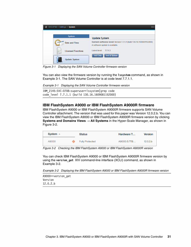
Figure 3-1 Displaying the SAN Volume Controller firmware version
You can also view the firmware version by running the lssystem command, as shown in Example 3-1. The SAN Volume Controller is at code level 7.7.1.1.
Example 3-1 Displaying the SAN Volume Controller firmware version
IBM_2145:SVC-0708:superuser>lssystem|grep codecode_level 7.7.1.1 (build 130.16.1609081152000)
IBM FlashSystem A9000 or IBM FlashSystem A9000R firmwareIBM FlashSystem A9000 or IBM FlashSystem A9000R firmware supports SAN Volume Controller attachment. The version that was used for this paper was Version 12.0.2.b. You can view the IBM FlashSystem A9000 or IBM FlashSystem A9000R firmware version by clicking Systems and Domains Views → All Systems in the Hyper-Scale Manager, as shown in Figure 3-2.
Figure 3-2 Checking the IBM FlashSystem A9000 or IBM FlashSystem A9000R version
You can check IBM FlashSystem A9000 or IBM FlashSystem A9000R firmware version by using the version_get XIV command-line interface (XCLI) command, as shown in Example 3-2.
Example 3-2 Displaying the IBM FlashSystem A9000 or IBM FlashSystem A9000R firmware version
A9000>>version_getVersion 12.0.2.b
Chapter 3. IBM FlashSystem A9000 or IBM FlashSystem A9000R with SAN Volume Controller 31
3.3 Zoning considerations
An IBM FlashSystem A9000 system has a fixed configuration with three grid elements, with a total of 12 Fibre Channel (FC) ports. A preferred practice is to restrict ports 2 and 4 of each grid controller for replication/migration use, and use ports 1 and 3 for host access. However, in this paper, any replication or migration is done through the SAN Volume Controller, so it is possible, if sharing an IBM FlashSystem A9000 or IBM FlashSystem A9000R system, to use ports 1 and 3 for one cluster, and ports 2 and 4 for another cluster. Port 4 must be set to target mode for this to work. Assume a single cluster that uses only ports 1 and 3 for examples in this book. For the example IBM FlashSystem A9000 system, there are six paths to the SAN Volume Controller cluster, ports 1 and 3 from each grid controller.
There are two models available for the IBM FlashSystem A9000 and IBM FlashSystem A9000R systems: Models 415 and 425. For the IBM FlashSystem A9000 system, there is no change from a host connectivity perspective because both have three grid controllers. However, there are fewer options for the IBM FlashSystem A9000R 425 model because it scales to only four grid elements, as opposed to six grid elements for the 415 model.
The IBM FlashSystem A9000R 415 system has more choices because there are multiple configurations, as shown in Table 3-2.
Table 3-2 Number of host ports in an IBM FlashSystem A9000R 415 system
Table 3-3 shows the number of host ports in an IBM FlashSystem A9000R 425 system.
Table 3-3 Number of host ports in an IBM FlashSystem A9000R 425 system
However, the SAN Volume Controller can support only 16 worldwide port names (WWPNs) from any single worldwide node name (WWNN). An IBM FlashSystem A9000 or IBM FlashSystem A9000R system has only one WWNN, so you are limited to 16 ports to any IBM FlashSystem A9000R system.
Table 3-4 on page 33 and Table 3-5 on page 33 shows same tables, but with columns added to show how many and which ports can be used for connectivity. The assumption is a dual fabric, with ports 1 in one fabric, and ports 3 in the other.
Grid elements Total host ports that are available
2 8
3 12
4 16
5 20
6 24
Grid elements Total host ports that are available
2 8
3 12
4 16
32 IBM FlashSystem A9000 and A9000R, IBM XIV, and IBM Spectrum Accelerate with IBM SVC Best Practices

For the 4-grid element system, it is possible to attach 16 ports because that is the maximum that SAN Volume Controller allows. For the 5- and 6-grid element systems, it possible to use more ports up to the 16 maximum, but that is not recommended because it might create unbalanced work loads to the grid controllers with two ports attached.
For the 425 model, as the maximum number of host ports is 16, use both ports from all grid controllers because that does not exceed the SAN Volume Controller maximum of 16.
Table 3-4 Host connections to SAN Volume Controller for 415 model
Table 3-5 Host connections to the SAN Volume Controller for 425 model
3.3.1 Determining IBM FlashSystem A9000 or IBM FlashSystem A9000R worldwide port names
IBM FlashSystem A9000 or IBM FlashSystem A9000R WWPNs are in the same format as the XIV system, that is, the 50:01:73:8x:xx:xx:RR:MP format, which is described in 2.3.2, “Determining XIV WWPNs” on page 9.
Grid elements Total host ports that are available
Total ports that are connected to the SAN Volume Controller
Actual ports that are connected
2 8 8 All controllers, ports 1 and 3
3 12 12 All controllers, ports 1 and 3
4 16 8 Controllers 1 - 4, port 1Controllers 5 - 8, port 3
5 20 10 Controllers 1 - 5, port 1Controllers 6 - 10, port 3
6 24 12 Controllers 1 - 6, port 1Controllers 7 - 12, port 3
Grid elements Total host ports that are available
Total ports that are connected to the SAN Volume Controller
Actual ports that are connected
2 8 8 All controllers, ports 1 and 3
3 12 12 All controllers, ports 1 and 3
4 16 16 All controllers, ports 1 and 3
Chapter 3. IBM FlashSystem A9000 or IBM FlashSystem A9000R with SAN Volume Controller 33
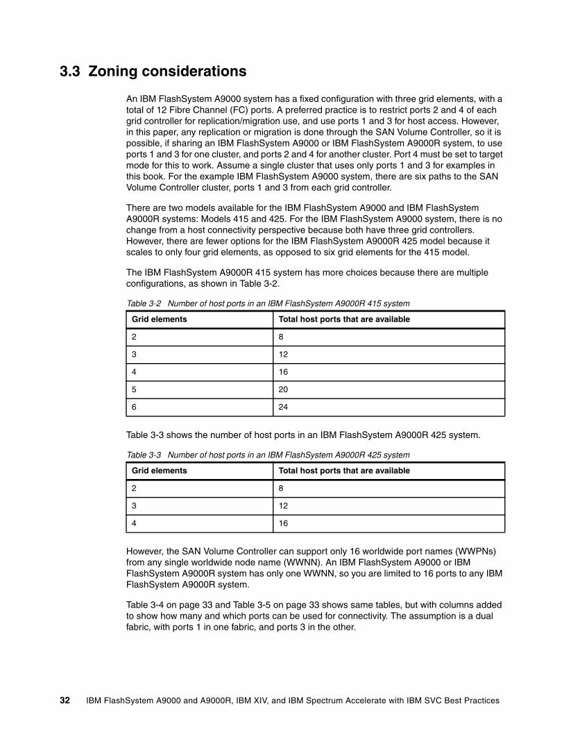
To display IBM FlashSystem A9000 or IBM FlashSystem A9000R WWPNs, click Systems and Domains Views, select the system, click Panel, find the port, and click View/Edit FC port, as shown in Figure 3-3. You can also use the XCLI and run the fc_port_list command, as shown in Example 3-3.
Figure 3-3 IBM FlashSystem A9000 or IBM FlashSystem A9000R WWPNs
The output that is shown in Example 3-3 lists the four ports in Module 4.
Example 3-3 Listing of IBM FlashSystem A9000 or IBM FlashSystem A9000R Fibre Channel host ports
ITSO_Tuc_A9000R>>fc_port_list module=1:Module:4Component ID Status Currently Functioning WWPN ....1:FC_Port:4:1 OK yes 5001738053980140 ....1:FC_Port:4:2 OK yes 5001738053880141 ....1:FC_Port:4:3 OK yes 5001738053980142 ....1:FC_Port:4:4 OK yes 5001738053980143 ....
3.3.2 Sharing IBM FlashSystem A9000 or IBM FlashSystem A9000R host ports
It is possible to share IBM FlashSystem A9000 or IBM FlashSystem A9000R host ports between a SAN Volume Controller cluster and non-SAN Volume Controller hosts, or between two different SAN Volume Controller clusters. Zone the IBM FlashSystem A9000 or IBM FlashSystem A9000R host ports on each grid controller to either SAN Volume Controller or any other hosts as required.
3.3.3 Zoning rules
For SAN Volume Controller nodes with only four ports (older hardware), the storage-system-to-SAN Volume Controller zone must contain all of the IBM FlashSystem A9000 or IBM FlashSystem A9000R ports and all of the SAN Volume Controller ports in that fabric. This is known as one big zone. This preference is relatively unique to SAN Volume Controller.
For nodes with more than four ports (CG8 with the appropriate RPQ, DH8 or newer), the concept of the one big zone still exists, but it is just the ports that are used for host and storage connectivity. For more information about port usage and zoning in SAN Volume Controller, see Implementing the IBM System Storage SAN Volume Controller with IBM Spectrum Virtualize V7.8, SG24-7933.
34 IBM FlashSystem A9000 and A9000R, IBM XIV, and IBM Spectrum Accelerate with IBM SVC Best Practices
For SAN Volume Controller zoning, follow these rules:
� With current SAN Volume Controller firmware levels, do not zone more than 16 WWPNs from a single WWNN to a SAN Volume Controller cluster. Because the IBM FlashSystem A9000 or IBM FlashSystem A9000R system has only one WWNN, zone no more than 16 IBM FlashSystem A9000 or IBM FlashSystem A9000R host ports to a specific SAN Volume Controller cluster. If you follow the suggestions in Table 3-5 on page 33, this restriction is not a concern.
� All nodes in a SAN Volume Controller cluster must be able to see the same set of IBM FlashSystem A9000 or IBM FlashSystem A9000R host ports. Operation in a mode where two nodes see a different set of host ports on the same IBM FlashSystem A9000 or IBM FlashSystem A9000R system results in the controller showing as degraded on the SAN Volume Controller, so the system error log requests a repair.
3.4 Volume size for IBM FlashSystem A9000 or IBM FlashSystem A9000R with SAN Volume Controller
There are several considerations when you are attaching an IBM FlashSystem A9000 or IBM FlashSystem A9000R system to a SAN Volume Controller. Estimated data reduction is important because that helps determine volume size.
IBM FlashSystem A9000 or IBM FlashSystem A9000R systems always have data reduction on, and because of the grid architecture, they can use all the resources of the grid for the active I/Os. Data reduction should be done at the IBM FlashSystem A9000 or IBM FlashSystem A9000R system, and not at the SAN Volume Controller.
Regarding what volume size and how many volumes, the preferred approach is to run the data reduction estimation tool that is found at the following website to know the total data reduction ratio that you expect to get:
https://www.ibm.com/support/fixcentral/
The next best case is you know the compression ratio of the data, and the worst case is that you do not have any of that information. When confronting this worst case scenario, you can use a data reduction ratio of 2.5:1. In any case, calculate the effective capacity of the IBM FlashSystem A9000 or IBM FlashSystem A9000R system by multiplying usable capacity times the data reduction ratio, and then divide by the (number of paths times 2) to get the volume size.
For IBM FlashSystem A9000 or IBM FlashSystem A9000R systems, use a minimum of 16 volumes for best performance, which leads to a number of volumes of number of paths times 3 for an IBM FlashSystem A9000 system, if you are using two ports per grid controller.
As an example, take a 5-grid element IBM FlashSystem A9000R system that uses a 29 TB IBM FlashSystem 900s system. Run the compression estimation tool, and you get a 3.9:1 compression ratio. The workload does not include virtual desktop infrastructure (VDI), so expect only nominal data deduplication rates. In this case, assume an overall data reduction ratio of 4:1. Calculate the effective capacity of the IBM FlashSystem A9000R system as 4 * 5 * 29 = 580 TB. In this example, there is a 5-grid element IBM FlashSystem A9000R system with 10 paths that are zoned to the SAN Volume Controller, so divide by 20 to get 29 TB. Create twenty 29-TB volumes to map to the SAN Volume Controller.
Chapter 3. IBM FlashSystem A9000 or IBM FlashSystem A9000R with SAN Volume Controller 35
Look at one more example, that is, a 4-grid element IBM FlashSystem A9000R model 425 with 180 TB IBM FlashSystem 900s system. The results of the data reduction estimation tool provide an estimate of 4.5:1. Calculate the effective capacity as 4 * 4.5 * 180 = 3240 TB. Divide this number by 32 (16 paths * 2) to get 32 volumes at 101.85 TB each. In cases where the original volume size is more than 128 TB, increase the volume count because 128 TB is the maximum managed disk (MDisk) size when using a 1 GiB extent size. Alternately, change the extent size to 2 GB, and that allows for larger volumes, as shown in Table 2-7 on page 17.
Consider an IBM FlashSystem A9000 system, which has three grid controllers that use one 29 TB Flash Enclosure. By using two ports on each grid controller, you use six ports in total. You have a 4:1 data reduction ratio. Calculate the effective capacity of the IBM FlashSystem A9000 system as 4 * 29 TB = 116 TB. You have six paths that are zoned to the SAN Volume Controller, so divide by 18 (3 * 6 paths) to get 6.44 TB. Create eighteen 6.44 TB volumes to map to the SAN Volume Controller.
3.4.1 SCSI queue depth considerations
For an IBM FlashSystem A9000 or IBM FlashSystem A9000R system, the number of volumes is based on the number of paths. As described earlier, changing the extent size might be required because of the maximum volume size. But, because there is less variation in the MDisk count, queue depth is not as an important factor as before. Using a 6-grid element IBM FlashSystem A9000R system with a 57 TB IBM FlashSystem 900s system, a data reduction rate of 3:1, and plugging it into the queue depth calculation by using an 8-node cluster yields the following result:
Q = ((12 ports*1000)/8 nodes)/24 MDisks = 62.5
This amount is well above the needed value. Even for the largest configuration, because you are typically creating a smaller number of larger volumes, the queue depth does not become a limiting factor.
3.4.2 Creating IBM FlashSystem A9000 or IBM FlashSystem A9000R volumes that are the same size as SAN Volume Controller VDisks
To create an IBM FlashSystem A9000 or IBM FlashSystem A9000R volume that is the same size as an existing SAN Volume Controller virtual disk (VDisk), you must use the vol_create command, as shown in Example 3-4. This command is typically used only for a transition to or from Image mode.
To create a volume of identical size, you must specify the volume size in blocks by using the size_blocks parameter, which can be specified only through the XCLI. A block has the size of 512 bytes.
Example 3-4 Creating a volume with a specific block size
vol_create vol=ITSO_image pool=ITSO_pool size_blocks=3125704704
3.4.3 Creating managed disk groups
All volumes that are presented by the IBM FlashSystem A9000 or IBM FlashSystem A9000R system to the SAN Volume Controller are represented as MDisks, which are then grouped into one or more MDisk groups or pools. Your decision is about how many MDisk groups to use.
36 IBM FlashSystem A9000 and A9000R, IBM XIV, and IBM Spectrum Accelerate with IBM SVC Best Practices
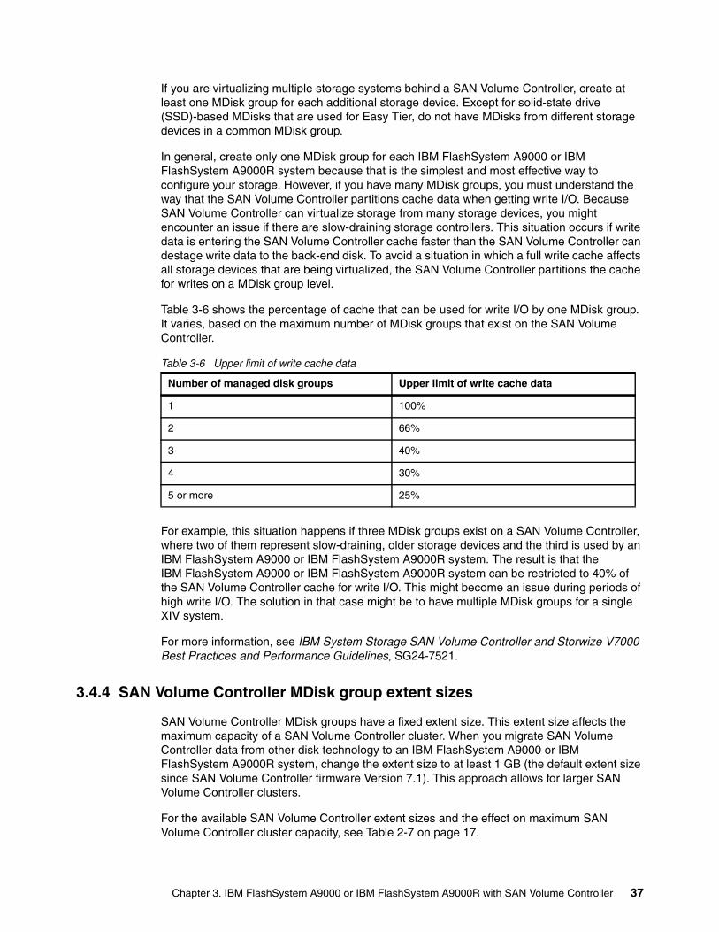
If you are virtualizing multiple storage systems behind a SAN Volume Controller, create at least one MDisk group for each additional storage device. Except for solid-state drive (SSD)-based MDisks that are used for Easy Tier, do not have MDisks from different storage devices in a common MDisk group.
In general, create only one MDisk group for each IBM FlashSystem A9000 or IBM FlashSystem A9000R system because that is the simplest and most effective way to configure your storage. However, if you have many MDisk groups, you must understand the way that the SAN Volume Controller partitions cache data when getting write I/O. Because SAN Volume Controller can virtualize storage from many storage devices, you might encounter an issue if there are slow-draining storage controllers. This situation occurs if write data is entering the SAN Volume Controller cache faster than the SAN Volume Controller can destage write data to the back-end disk. To avoid a situation in which a full write cache affects all storage devices that are being virtualized, the SAN Volume Controller partitions the cache for writes on a MDisk group level.
Table 3-6 shows the percentage of cache that can be used for write I/O by one MDisk group. It varies, based on the maximum number of MDisk groups that exist on the SAN Volume Controller.
Table 3-6 Upper limit of write cache data
For example, this situation happens if three MDisk groups exist on a SAN Volume Controller, where two of them represent slow-draining, older storage devices and the third is used by an IBM FlashSystem A9000 or IBM FlashSystem A9000R system. The result is that the IBM FlashSystem A9000 or IBM FlashSystem A9000R system can be restricted to 40% of the SAN Volume Controller cache for write I/O. This might become an issue during periods of high write I/O. The solution in that case might be to have multiple MDisk groups for a single XIV system.
For more information, see IBM System Storage SAN Volume Controller and Storwize V7000 Best Practices and Performance Guidelines, SG24-7521.
3.4.4 SAN Volume Controller MDisk group extent sizes
SAN Volume Controller MDisk groups have a fixed extent size. This extent size affects the maximum capacity of a SAN Volume Controller cluster. When you migrate SAN Volume Controller data from other disk technology to an IBM FlashSystem A9000 or IBM FlashSystem A9000R system, change the extent size to at least 1 GB (the default extent size since SAN Volume Controller firmware Version 7.1). This approach allows for larger SAN Volume Controller clusters.
For the available SAN Volume Controller extent sizes and the effect on maximum SAN Volume Controller cluster capacity, see Table 2-7 on page 17.
Number of managed disk groups Upper limit of write cache data
1 100%
2 66%
3 40%
4 30%
5 or more 25%
Chapter 3. IBM FlashSystem A9000 or IBM FlashSystem A9000R with SAN Volume Controller 37
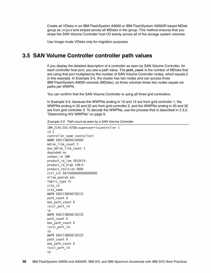
Create all VDisks in an IBM FlashSystem A9000 or IBM FlashSystem A9000R based MDisk group as striped and striped across all MDisks in the group. This method ensures that you stripe the SAN Volume Controller host I/O evenly across all of the storage system volumes.
Use Image mode VDisks only for migration purposes.
3.5 SAN Volume Controller controller path values
If you display the detailed description of a controller as seen by SAN Volume Controller, for each controller host port, you see a path value. The path_count is the number of MDisks that are using that port multiplied by the number of SAN Volume Controller nodes, which equals 2 in this example. In Example 3-5, the cluster has two nodes and can access three IBM FlashSystem A9000 volumes (MDisks), so three volumes times two nodes equals six paths per WWPN.
You can confirm that the SAN Volume Controller is using all three grid controllers.
In Example 3-5, because the WWPNs ending in 10 and 12 are from grid controller 1, the WWPNs ending in 20 and 22 are from grid controller 2, and the WWPNs ending in 30 and 32 are from grid controller 3. To decode the WWPNs, use the process that is described in 2.3.2, “Determining XIV WWPNs” on page 9.
Example 3-5 Path count as seen by a SAN Volume Controller
IBM_2145:SVC-0708:superuser>lscontroller 1id 1controller_name controller1WWNN 5001738056730000mdisk_link_count 3max_mdisk_link_count 3degraded novendor_id IBMproduct_id_low 2810XIV-product_id_high LUN-0product_revision 0000ctrl_s/n 56730000000000000000allow_quorum yesfabric_type fcsite_idsite_nameWWPN 5001738056730112path_count 6max_path_count 6iscsi_port_idipWWPN 5001738056730132path_count 6max_path_count 6iscsi_port_idipWWPN 5001738056730122path_count 6max_path_count 6iscsi_port_idip
38 IBM FlashSystem A9000 and A9000R, IBM XIV, and IBM Spectrum Accelerate with IBM SVC Best Practices
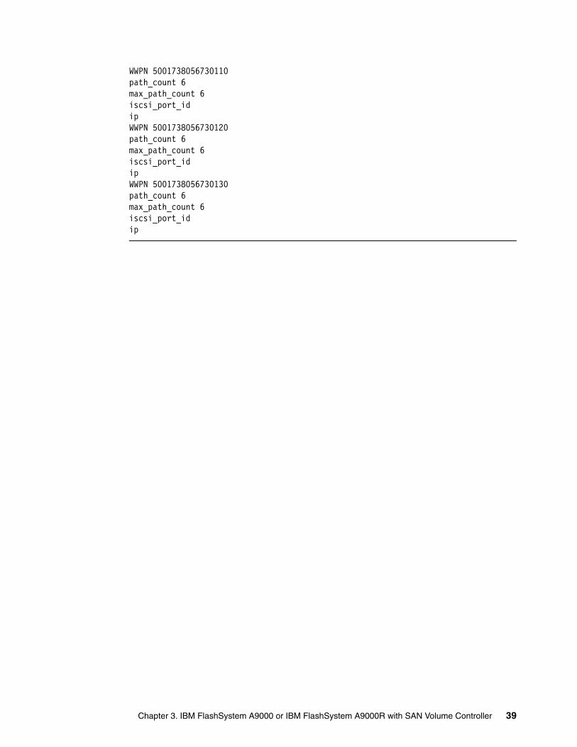
WWPN 5001738056730110path_count 6max_path_count 6iscsi_port_idipWWPN 5001738056730120path_count 6max_path_count 6iscsi_port_idipWWPN 5001738056730130path_count 6max_path_count 6iscsi_port_idip
Chapter 3. IBM FlashSystem A9000 or IBM FlashSystem A9000R with SAN Volume Controller 39
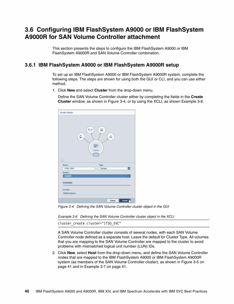
3.6 Configuring IBM FlashSystem A9000 or IBM FlashSystem A9000R for SAN Volume Controller attachment
This section presents the steps to configure the IBM FlashSystem A9000 or IBM FlashSystem A9000R and SAN Volume Controller combination.
3.6.1 IBM FlashSystem A9000 or IBM FlashSystem A9000R setup
To set up an IBM FlashSystem A9000 or IBM FlashSystem A9000R system, complete the following steps. The steps are shown for using both the GUI or CLI, and you can use either method.
1. Click New and select Cluster from the drop-down menu.
Define the SAN Volume Controller cluster either by completing the fields in the Create Cluster window, as shown in Figure 3-4, or by using the XCLI, as shown Example 3-6.
Figure 3-4 Defining the SAN Volume Controller cluster object in the GUI
Example 3-6 Defining the SAN Volume Controller cluster object in the XCLI
cluster_create cluster="ITSO_SVC"
A SAN Volume Controller cluster consists of several nodes, with each SAN Volume Controller node defined as a separate host. Leave the default for Cluster Type. All volumes that you are mapping to the SAN Volume Controller are mapped to the cluster to avoid problems with mismatched logical unit number (LUN) IDs.
2. Click New, select Host from the drop-down menu, and define the SAN Volume Controller nodes that are mapped to the IBM FlashSystem A9000 or IBM FlashSystem A9000R system (as members of the SAN Volume Controller cluster), as shown in Figure 3-5 on page 41 and in Example 3-7 on page 41.
40 IBM FlashSystem A9000 and A9000R, IBM XIV, and IBM Spectrum Accelerate with IBM SVC Best Practices
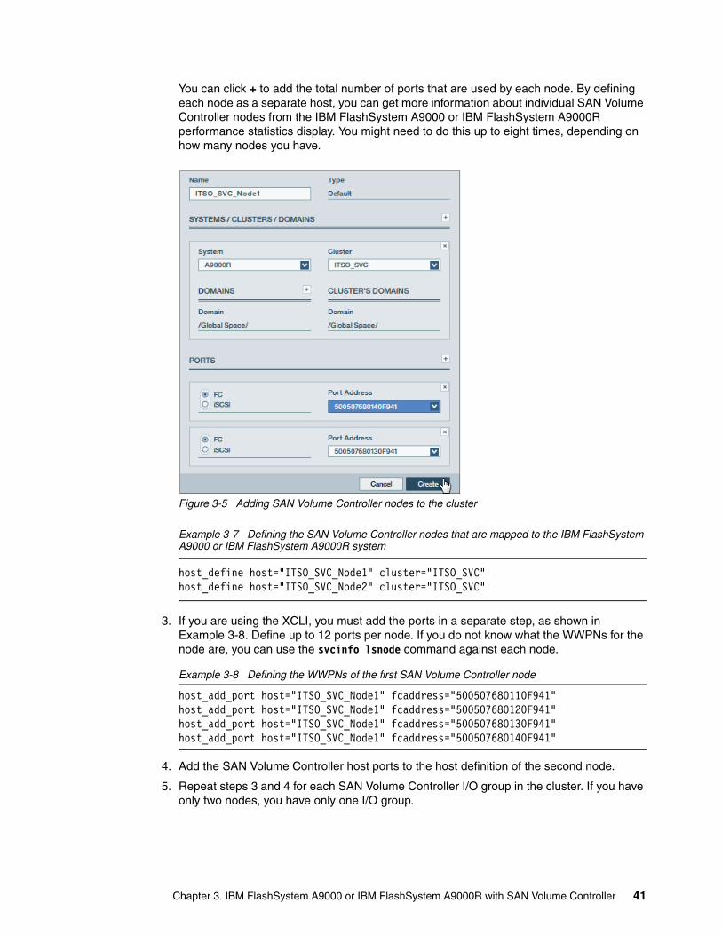
You can click + to add the total number of ports that are used by each node. By defining each node as a separate host, you can get more information about individual SAN Volume Controller nodes from the IBM FlashSystem A9000 or IBM FlashSystem A9000R performance statistics display. You might need to do this up to eight times, depending on how many nodes you have.
Figure 3-5 Adding SAN Volume Controller nodes to the cluster
Example 3-7 Defining the SAN Volume Controller nodes that are mapped to the IBM FlashSystem A9000 or IBM FlashSystem A9000R system
host_define host="ITSO_SVC_Node1" cluster="ITSO_SVC"host_define host="ITSO_SVC_Node2" cluster="ITSO_SVC"
3. If you are using the XCLI, you must add the ports in a separate step, as shown in Example 3-8. Define up to 12 ports per node. If you do not know what the WWPNs for the node are, you can use the svcinfo lsnode command against each node.
Example 3-8 Defining the WWPNs of the first SAN Volume Controller node
host_add_port host="ITSO_SVC_Node1" fcaddress="500507680110F941"host_add_port host="ITSO_SVC_Node1" fcaddress="500507680120F941"host_add_port host="ITSO_SVC_Node1" fcaddress="500507680130F941"host_add_port host="ITSO_SVC_Node1" fcaddress="500507680140F941"
4. Add the SAN Volume Controller host ports to the host definition of the second node.
5. Repeat steps 3 and 4 for each SAN Volume Controller I/O group in the cluster. If you have only two nodes, you have only one I/O group.
Chapter 3. IBM FlashSystem A9000 or IBM FlashSystem A9000R with SAN Volume Controller 41
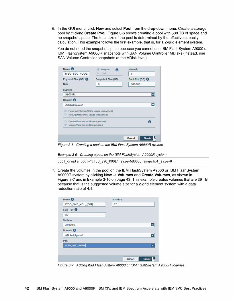
6. In the GUI menu, click New and select Pool from the drop-down menu. Create a storage pool by clicking Create Pool. Figure 3-6 shows creating a pool with 580 TB of space and no snapshot space. The total size of the pool is determined by the effective capacity calculation. This example follows the first example, that is, for a 2-grid element system.
You do not need the snapshot space because you cannot use IBM FlashSystem A9000 or IBM FlashSystem A9000R snapshots with SAN Volume Controller MDisks (instead, use SAN Volume Controller snapshots at the VDisk level).
Figure 3-6 Creating a pool on the IBM FlashSystem A9000R system
Example 3-9 Creating a pool on the IBM FlashSystem A9000R system
pool_create pool="ITSO_SVC_POOL" size=580000 snapshot_size=0
7. Create the volumes in the pool on the IBM FlashSystem A9000 or IBM FlashSystem A9000R system by clicking New → Volumes and Create Volumes, as shown in Figure 3-7 and in Example 3-10 on page 43. This example creates volumes that are 29 TB because that is the suggested volume size for a 2-grid element system with a data reduction ratio of 4:1.
Figure 3-7 Adding IBM FlashSystem A9000 or IBM FlashSystem A9000R volumes
42 IBM FlashSystem A9000 and A9000R, IBM XIV, and IBM Spectrum Accelerate with IBM SVC Best Practices

Example 3-10 Commands to create IBM FlashSystem A9000 or IBM FlashSystem A9000R volumes for use by the SAN Volume Controller
vol_create size=29045 pool="ITSO_SVC_POOL" vol="ITSO_SVC_VOL_001"...vol_create size=29045 pool="ITSO_SVC_POOL" vol="ITSO_SVC_VOL_020"
8. Map the volumes by clicking Pools and Volumes Views → Volumes, use the filter to show only volumes in the ITSO_SVC_POOL pool on the IBM FlashSystem A9000R system, select all the volumes, click Mapping in the Hub view, and select Cluster, as shown in Figure 3-8 and Example 3-11.
Figure 3-8 Mapping IBM FlashSystem A9000 or IBM FlashSystem A9000R volumes to the SAN Volume Controller cluster
Example 3-11 Commands to map volumes to the SAN Volume Controller cluster
map_vol cluster="ITSO_SVC" override=yes vol="ITSO_SVC_VOL_001" lun="1"...map_vol cluster="ITSO_SVC" override=yes vol="ITSO_SVC_VOL_020" lun="20"
Important: Even though a 29-TB volume was requested, the IBM FlashSystem A9000 allocation unit of 103 GB still comes into play. The volumes that are created are actually 290045 GB, so the pool size must be slightly larger than 580 TB. Conversely, a slightly smaller volume size of 28942 could have been specified.
Important: All volumes must be mapped with the same LUN ID to all nodes of a SAN Volume Controller cluster. Therefore, map the volumes to the cluster, not to individual nodes of the cluster.
Tip: The IBM FlashSystem A9000 or IBM FlashSystem A9000R GUI normally reserves LUN ID 0 for in-band management. The SAN Volume Controller cannot take advantage of this ID, but there is no adverse effect.
Chapter 3. IBM FlashSystem A9000 or IBM FlashSystem A9000R with SAN Volume Controller 43
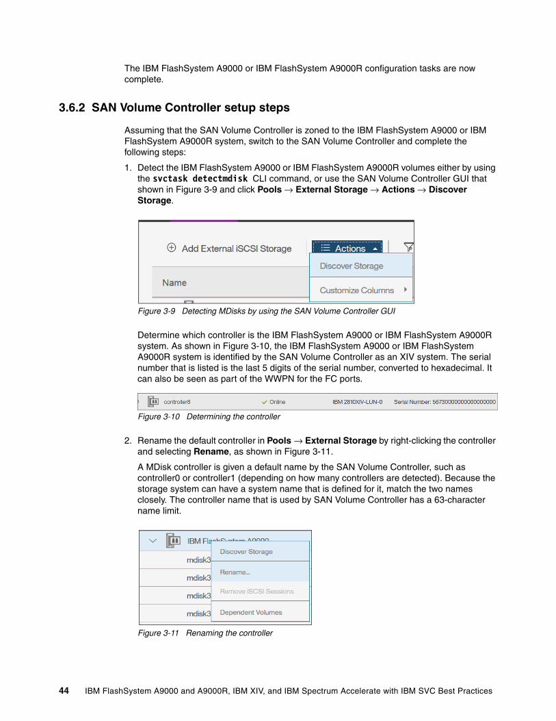
The IBM FlashSystem A9000 or IBM FlashSystem A9000R configuration tasks are now complete.
3.6.2 SAN Volume Controller setup steps
Assuming that the SAN Volume Controller is zoned to the IBM FlashSystem A9000 or IBM FlashSystem A9000R system, switch to the SAN Volume Controller and complete the following steps:
1. Detect the IBM FlashSystem A9000 or IBM FlashSystem A9000R volumes either by using the svctask detectmdisk CLI command, or use the SAN Volume Controller GUI that shown in Figure 3-9 and click Pools → External Storage → Actions → Discover Storage.
Figure 3-9 Detecting MDisks by using the SAN Volume Controller GUI
Determine which controller is the IBM FlashSystem A9000 or IBM FlashSystem A9000R system. As shown in Figure 3-10, the IBM FlashSystem A9000 or IBM FlashSystem A9000R system is identified by the SAN Volume Controller as an XIV system. The serial number that is listed is the last 5 digits of the serial number, converted to hexadecimal. It can also be seen as part of the WWPN for the FC ports.
Figure 3-10 Determining the controller
2. Rename the default controller in Pools → External Storage by right-clicking the controller and selecting Rename, as shown in Figure 3-11.
A MDisk controller is given a default name by the SAN Volume Controller, such as controller0 or controller1 (depending on how many controllers are detected). Because the storage system can have a system name that is defined for it, match the two names closely. The controller name that is used by SAN Volume Controller has a 63-character name limit.
Figure 3-11 Renaming the controller
44 IBM FlashSystem A9000 and A9000R, IBM XIV, and IBM Spectrum Accelerate with IBM SVC Best Practices
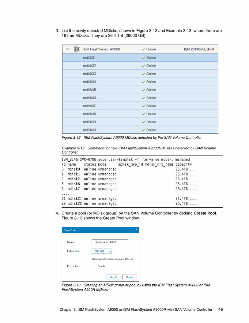
3. List the newly detected MDisks, shown in Figure 3-12 and Example 3-12, where there are 18 free MDisks. They are 26.4 TiB (29000 GB).
Figure 3-12 IBM FlashSystem A9000 MDisks detected by the SAN Volume Controller
Example 3-12 Command for new IBM FlashSystem A9000R MDisks detected by SAN Volume Controller
IBM_2145:SVC-0708:superuser>lsmdisk -filtervalue mode=unmanagedid name status mode mdisk_grp_id mdisk_grp_name capacity 0 mdisk0 online unmanaged 26.4TB ....1 mdisk1 online unmanaged 26.4TB ....2 mdisk2 online unmanaged 26.4TB ....6 mdisk6 online unmanaged 26.4TB ....7 mdisk7 online unmanaged 26.4TB ........21 mdisk21 online unmanaged 26.4TB ....22 mdisk22 online unmanaged 26.4TB ....
4. Create a pool (or MDisk group) on the SAN Volume Controller by clicking Create Pool. Figure 3-13 shows the Create Pool window.
Figure 3-13 Creating an MDisk group or pool by using the IBM FlashSystem A9000 or IBM FlashSystem A900R MDisks
Chapter 3. IBM FlashSystem A9000 or IBM FlashSystem A9000R with SAN Volume Controller 45
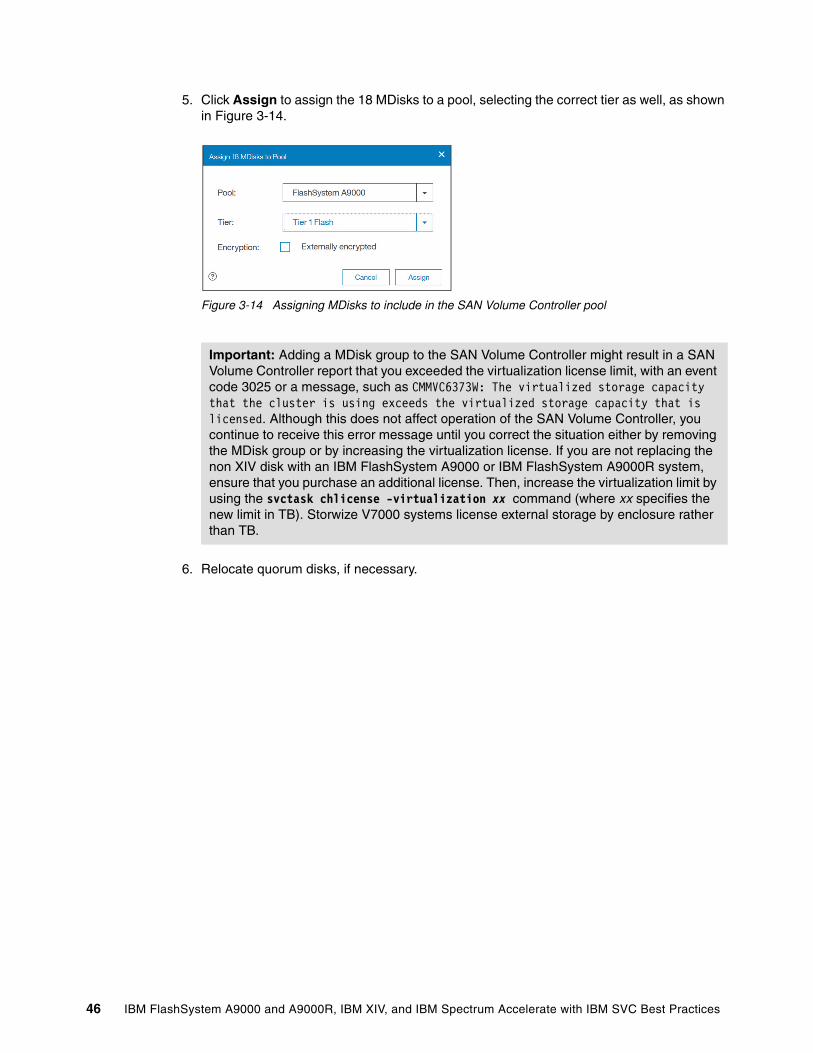
5. Click Assign to assign the 18 MDisks to a pool, selecting the correct tier as well, as shown in Figure 3-14.
Figure 3-14 Assigning MDisks to include in the SAN Volume Controller pool
6. Relocate quorum disks, if necessary.
Important: Adding a MDisk group to the SAN Volume Controller might result in a SAN Volume Controller report that you exceeded the virtualization license limit, with an event code 3025 or a message, such as CMMVC6373W: The virtualized storage capacity that the cluster is using exceeds the virtualized storage capacity that is licensed. Although this does not affect operation of the SAN Volume Controller, you continue to receive this error message until you correct the situation either by removing the MDisk group or by increasing the virtualization license. If you are not replacing the non XIV disk with an IBM FlashSystem A9000 or IBM FlashSystem A9000R system, ensure that you purchase an additional license. Then, increase the virtualization limit by using the svctask chlicense -virtualization xx command (where xx specifies the new limit in TB). Storwize V7000 systems license external storage by enclosure rather than TB.
46 IBM FlashSystem A9000 and A9000R, IBM XIV, and IBM Spectrum Accelerate with IBM SVC Best Practices
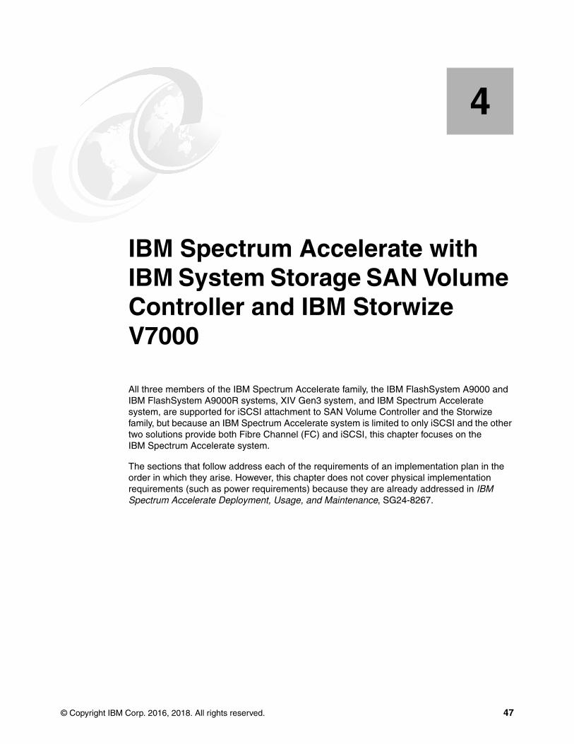
Chapter 4. IBM Spectrum Accelerate with IBM System Storage SAN Volume Controller and IBM Storwize V7000
All three members of the IBM Spectrum Accelerate family, the IBM FlashSystem A9000 and IBM FlashSystem A9000R systems, XIV Gen3 system, and IBM Spectrum Accelerate system, are supported for iSCSI attachment to SAN Volume Controller and the Storwize family, but because an IBM Spectrum Accelerate system is limited to only iSCSI and the other two solutions provide both Fibre Channel (FC) and iSCSI, this chapter focuses on the IBM Spectrum Accelerate system.
The sections that follow address each of the requirements of an implementation plan in the order in which they arise. However, this chapter does not cover physical implementation requirements (such as power requirements) because they are already addressed in IBM Spectrum Accelerate Deployment, Usage, and Maintenance, SG24-8267.
4
© Copyright IBM Corp. 2016, 2018. All rights reserved. 47

4.1 Summary of steps for attaching an IBM Spectrum Accelerate system to a Storwize V7000 system
Review the following topics when you are placing a new IBM Spectrum Accelerate system behind a Storwize V7000 system:
� IBM Spectrum Accelerate and Storwize V7000 interoperability
� iSCSI setup
� Volume size for an IBM Spectrum Accelerate system with SAN Volume Controller and Storwize V7000 systems
� Configuring IBM Spectrum Accelerate for attachment to Storwize V7000
4.2 IBM Spectrum Accelerate and Storwize V7000 interoperability
Because Storwize V7000 -attached hosts do not communicate directly with the IBM Spectrum Accelerate system, only two interoperability considerations are covered in this section:
� Firmware versions � Copy functions
4.2.1 Firmware versions
Storwize V7000 and the IBM Spectrum Accelerate systems have minimum firmware requirements. Although the versions that are cited in this paper were current at the time of writing, they might have changed since then. To verify the current versions, see the IBM Systems Storage Interoperation Center (SSIC) and Storwize V7000 support websites:
� https://www-03.ibm.com/systems/support/storage/ssic/interoperability.wss � http://www.ibm.com/support/docview.wss?uid=ssg1S1003741
SAN Volume Controller and Storwize V7000 firmwareThe first firmware version that supports IBM Spectrum Accelerate family attachment through iSCSI is Version 7.7.1.1. You can display the firmware version by clicking Settings → System → Update System in the Storwize V7000 GUI, as shown in Figure 4-1.
Figure 4-1 Displaying the Storwize V7000 firmware version
48 IBM FlashSystem A9000 and A9000R, IBM XIV, and IBM Spectrum Accelerate with IBM SVC Best Practices
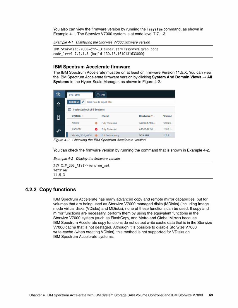
You also can view the firmware version by running the lssystem command, as shown in Example 4-1. The Storwize V7000 system is at code level 7.7.1.3.
Example 4-1 Displaying the Storwize V7000 firmware version
IBM_Storwize:v7000-ctr-13:superuser>lssystem|grep codecode_level 7.7.1.3 (build 130.16.1610131633000)
IBM Spectrum Accelerate firmwareThe IBM Spectrum Accelerate must be on at least on firmware Version 11.5.X. You can view the IBM Spectrum Accelerate firmware version by clicking System And Domain Views → All Systems in the Hyper-Scale Manager, as shown in Figure 4-2.
Figure 4-2 Checking the IBM Spectrum Accelerate version
You can check the firmware version by running the command that is shown in Example 4-2.
Example 4-2 Display the firmware version
XIV XIV_SDS_ATS1>>version_getVersion 11.5.3
4.2.2 Copy functions
IBM Spectrum Accelerate has many advanced copy and remote mirror capabilities, but for volumes that are being used as Storwize V7000 managed disks (MDisks) (including Image mode virtual disks (VDisks) and MDisks), none of these functions can be used. If copy and mirror functions are necessary, perform them by using the equivalent functions in the Storwize V7000 system (such as FlashCopy, and Metro and Global Mirror) because IBM Spectrum Accelerate copy functions do not detect write cache data that is in the Storwize V7000 cache that is not destaged. Although it is possible to disable Storwize V7000 write-cache (when creating VDisks), this method is not supported for VDisks on IBM Spectrum Accelerate systems.
Chapter 4. IBM Spectrum Accelerate with IBM System Storage SAN Volume Controller and IBM Storwize V7000 49
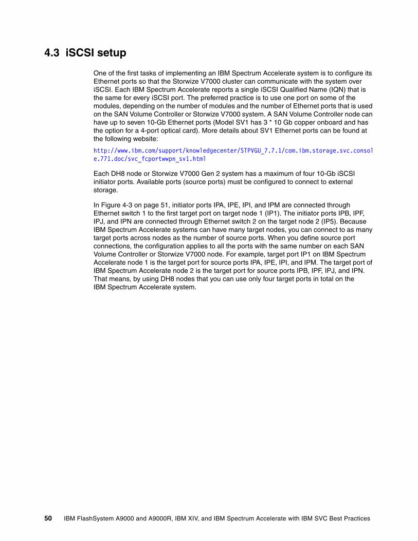
4.3 iSCSI setup
One of the first tasks of implementing an IBM Spectrum Accelerate system is to configure its Ethernet ports so that the Storwize V7000 cluster can communicate with the system over iSCSI. Each IBM Spectrum Accelerate reports a single iSCSI Qualified Name (IQN) that is the same for every iSCSI port. The preferred practice is to use one port on some of the modules, depending on the number of modules and the number of Ethernet ports that is used on the SAN Volume Controller or Storwize V7000 system. A SAN Volume Controller node can have up to seven 10-Gb Ethernet ports (Model SV1 has 3 * 10 Gb copper onboard and has the option for a 4-port optical card). More details about SV1 Ethernet ports can be found at the following website:
http://www.ibm.com/support/knowledgecenter/STPVGU_7.7.1/com.ibm.storage.svc.console.771.doc/svc_fcportwwpn_sv1.html
Each DH8 node or Storwize V7000 Gen 2 system has a maximum of four 10-Gb iSCSI initiator ports. Available ports (source ports) must be configured to connect to external storage.
In Figure 4-3 on page 51, initiator ports IPA, IPE, IPI, and IPM are connected through Ethernet switch 1 to the first target port on target node 1 (IP1). The initiator ports IPB, IPF, IPJ, and IPN are connected through Ethernet switch 2 on the target node 2 (IP5). Because IBM Spectrum Accelerate systems can have many target nodes, you can connect to as many target ports across nodes as the number of source ports. When you define source port connections, the configuration applies to all the ports with the same number on each SAN Volume Controller or Storwize V7000 node. For example, target port IP1 on IBM Spectrum Accelerate node 1 is the target port for source ports IPA, IPE, IPI, and IPM. The target port of IBM Spectrum Accelerate node 2 is the target port for source ports IPB, IPF, IPJ, and IPN. That means, by using DH8 nodes that you can use only four target ports in total on the IBM Spectrum Accelerate system.
50 IBM FlashSystem A9000 and A9000R, IBM XIV, and IBM Spectrum Accelerate with IBM SVC Best Practices
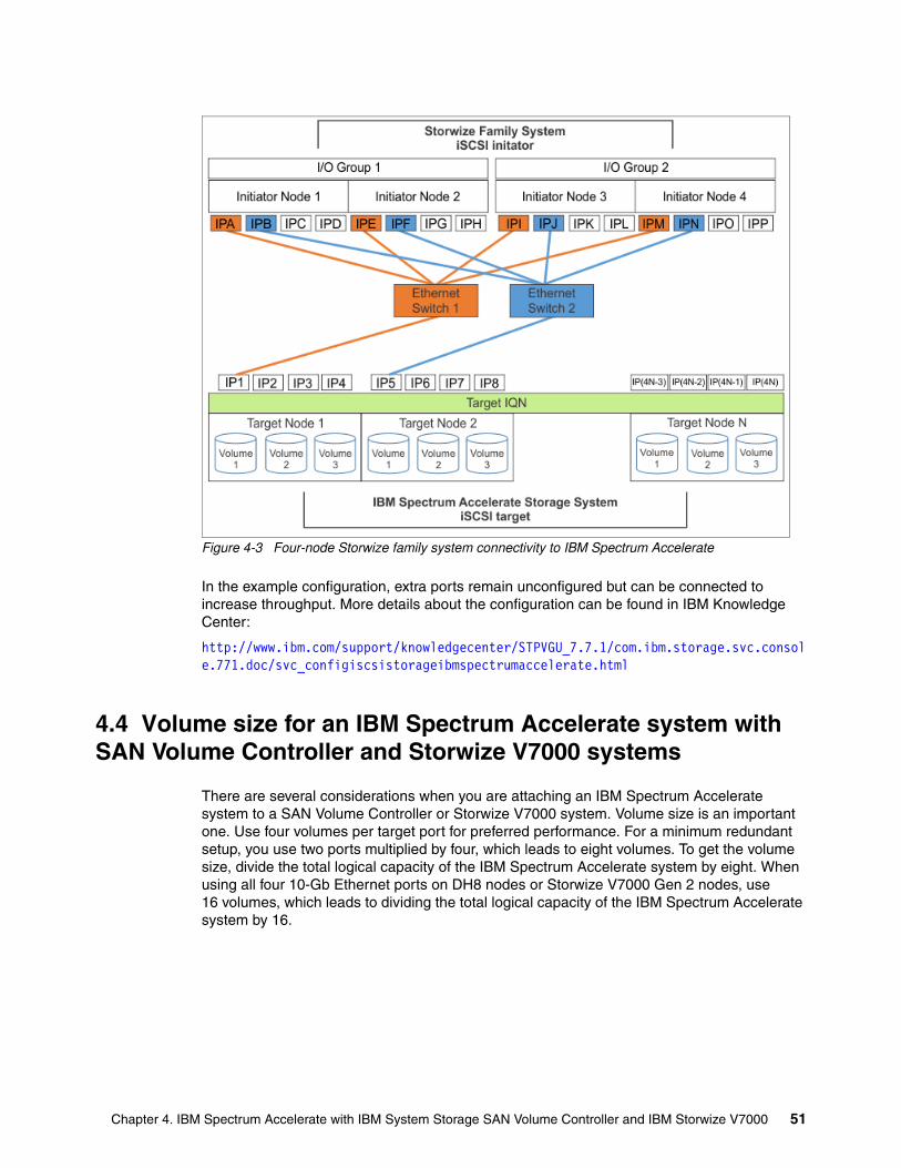
Figure 4-3 Four-node Storwize family system connectivity to IBM Spectrum Accelerate
In the example configuration, extra ports remain unconfigured but can be connected to increase throughput. More details about the configuration can be found in IBM Knowledge Center:
http://www.ibm.com/support/knowledgecenter/STPVGU_7.7.1/com.ibm.storage.svc.console.771.doc/svc_configiscsistorageibmspectrumaccelerate.html
4.4 Volume size for an IBM Spectrum Accelerate system with SAN Volume Controller and Storwize V7000 systems
There are several considerations when you are attaching an IBM Spectrum Accelerate system to a SAN Volume Controller or Storwize V7000 system. Volume size is an important one. Use four volumes per target port for preferred performance. For a minimum redundant setup, you use two ports multiplied by four, which leads to eight volumes. To get the volume size, divide the total logical capacity of the IBM Spectrum Accelerate system by eight. When using all four 10-Gb Ethernet ports on DH8 nodes or Storwize V7000 Gen 2 nodes, use 16 volumes, which leads to dividing the total logical capacity of the IBM Spectrum Accelerate system by 16.
Chapter 4. IBM Spectrum Accelerate with IBM System Storage SAN Volume Controller and IBM Storwize V7000 51
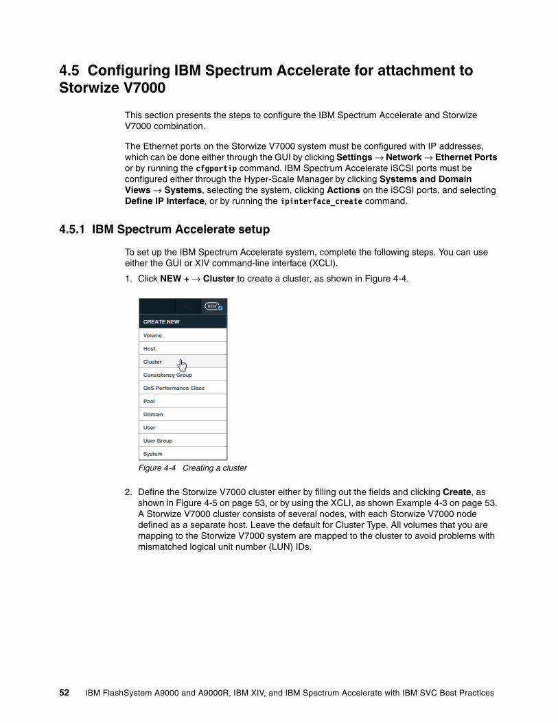
4.5 Configuring IBM Spectrum Accelerate for attachment to Storwize V7000
This section presents the steps to configure the IBM Spectrum Accelerate and Storwize V7000 combination.
The Ethernet ports on the Storwize V7000 system must be configured with IP addresses, which can be done either through the GUI by clicking Settings → Network → Ethernet Ports or by running the cfgportip command. IBM Spectrum Accelerate iSCSI ports must be configured either through the Hyper-Scale Manager by clicking Systems and Domain Views → Systems, selecting the system, clicking Actions on the iSCSI ports, and selecting Define IP Interface, or by running the ipinterface_create command.
4.5.1 IBM Spectrum Accelerate setup
To set up the IBM Spectrum Accelerate system, complete the following steps. You can use either the GUI or XIV command-line interface (XCLI).
1. Click NEW + → Cluster to create a cluster, as shown in Figure 4-4.
Figure 4-4 Creating a cluster
2. Define the Storwize V7000 cluster either by filling out the fields and clicking Create, as shown in Figure 4-5 on page 53, or by using the XCLI, as shown Example 4-3 on page 53. A Storwize V7000 cluster consists of several nodes, with each Storwize V7000 node defined as a separate host. Leave the default for Cluster Type. All volumes that you are mapping to the Storwize V7000 system are mapped to the cluster to avoid problems with mismatched logical unit number (LUN) IDs.
52 IBM FlashSystem A9000 and A9000R, IBM XIV, and IBM Spectrum Accelerate with IBM SVC Best Practices
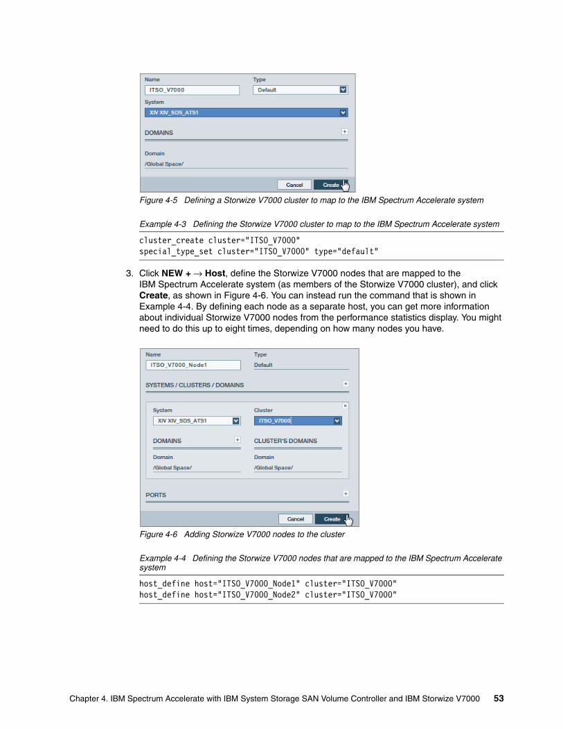
Figure 4-5 Defining a Storwize V7000 cluster to map to the IBM Spectrum Accelerate system
Example 4-3 Defining the Storwize V7000 cluster to map to the IBM Spectrum Accelerate system
cluster_create cluster="ITSO_V7000"special_type_set cluster="ITSO_V7000" type="default"
3. Click NEW + → Host, define the Storwize V7000 nodes that are mapped to the IBM Spectrum Accelerate system (as members of the Storwize V7000 cluster), and click Create, as shown in Figure 4-6. You can instead run the command that is shown in Example 4-4. By defining each node as a separate host, you can get more information about individual Storwize V7000 nodes from the performance statistics display. You might need to do this up to eight times, depending on how many nodes you have.
Figure 4-6 Adding Storwize V7000 nodes to the cluster
Example 4-4 Defining the Storwize V7000 nodes that are mapped to the IBM Spectrum Accelerate system
host_define host="ITSO_V7000_Node1" cluster="ITSO_V7000"host_define host="ITSO_V7000_Node2" cluster="ITSO_V7000"
Chapter 4. IBM Spectrum Accelerate with IBM System Storage SAN Volume Controller and IBM Storwize V7000 53
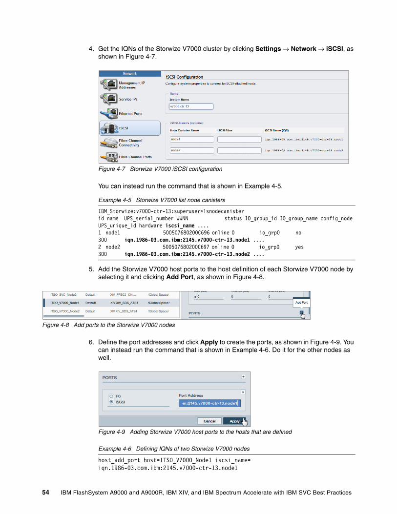
4. Get the IQNs of the Storwize V7000 cluster by clicking Settings → Network → iSCSI, as shown in Figure 4-7.
Figure 4-7 Storwize V7000 iSCSI configuration
You can instead run the command that is shown in Example 4-5.
Example 4-5 Storwize V7000 list node canisters
IBM_Storwize:v7000-ctr-13:superuser>lsnodecanisterid name UPS_serial_number WWNN status IO_group_id IO_group_name config_node UPS_unique_id hardware iscsi_name ....1 node1 500507680200C696 online 0 io_grp0 no 300 iqn.1986-03.com.ibm:2145.v7000-ctr-13.node1 ....2 node2 500507680200C697 online 0 io_grp0 yes 300 iqn.1986-03.com.ibm:2145.v7000-ctr-13.node2 ....
5. Add the Storwize V7000 host ports to the host definition of each Storwize V7000 node by selecting it and clicking Add Port, as shown in Figure 4-8.
Figure 4-8 Add ports to the Storwize V7000 nodes
6. Define the port addresses and click Apply to create the ports, as shown in Figure 4-9. You can instead run the command that is shown in Example 4-6. Do it for the other nodes as well.
Figure 4-9 Adding Storwize V7000 host ports to the hosts that are defined
Example 4-6 Defining IQNs of two Storwize V7000 nodes
host_add_port host=ITSO_V7000_Node1 iscsi_name= iqn.1986-03.com.ibm:2145.v7000-ctr-13.node1
54 IBM FlashSystem A9000 and A9000R, IBM XIV, and IBM Spectrum Accelerate with IBM SVC Best Practices
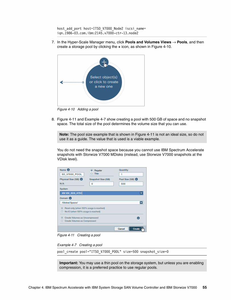
host_add_port host=ITSO_V7000_Node2 iscsi_name= iqn.1986-03.com.ibm:2145.v7000-ctr-13.node2
7. In the Hyper-Scale Manager menu, click Pools and Volumes Views → Pools, and then create a storage pool by clicking the + icon, as shown in Figure 4-10.
Figure 4-10 Adding a pool
8. Figure 4-11 and Example 4-7 show creating a pool with 500 GB of space and no snapshot space. The total size of the pool determines the volume size that you can use.
You do not need the snapshot space because you cannot use IBM Spectrum Accelerate snapshots with Storwize V7000 MDisks (instead, use Storwize V7000 snapshots at the VDisk level).
Figure 4-11 Creating a pool
Example 4-7 Creating a pool
pool_create pool="ITSO_V7000_POOL" size=500 snapshot_size=0
Note: The pool size example that is shown in Figure 4-11 is not an ideal size, so do not use it as a guide. The value that is used is a viable example.
Important: You may use a thin pool on the storage system, but unless you are enabling compression, it is a preferred practice to use regular pools.
Chapter 4. IBM Spectrum Accelerate with IBM System Storage SAN Volume Controller and IBM Storwize V7000 55
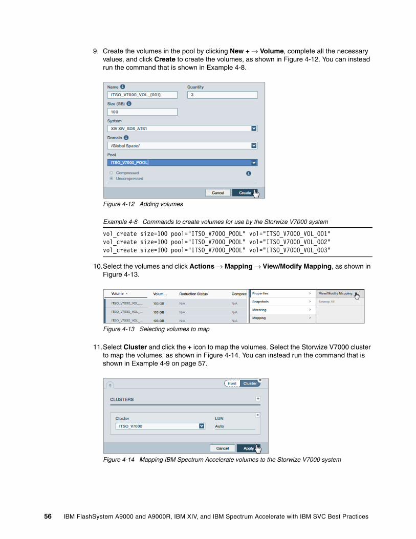
9. Create the volumes in the pool by clicking New + → Volume, complete all the necessary values, and click Create to create the volumes, as shown in Figure 4-12. You can instead run the command that is shown in Example 4-8.
Figure 4-12 Adding volumes
Example 4-8 Commands to create volumes for use by the Storwize V7000 system
vol_create size=100 pool="ITSO_V7000_POOL" vol="ITSO_V7000_VOL_001"vol_create size=100 pool="ITSO_V7000_POOL" vol="ITSO_V7000_VOL_002"vol_create size=100 pool="ITSO_V7000_POOL" vol="ITSO_V7000_VOL_003"
10.Select the volumes and click Actions → Mapping → View/Modify Mapping, as shown in Figure 4-13.
Figure 4-13 Selecting volumes to map
11.Select Cluster and click the + icon to map the volumes. Select the Storwize V7000 cluster to map the volumes, as shown in Figure 4-14. You can instead run the command that is shown in Example 4-9 on page 57.
Figure 4-14 Mapping IBM Spectrum Accelerate volumes to the Storwize V7000 system
56 IBM FlashSystem A9000 and A9000R, IBM XIV, and IBM Spectrum Accelerate with IBM SVC Best Practices
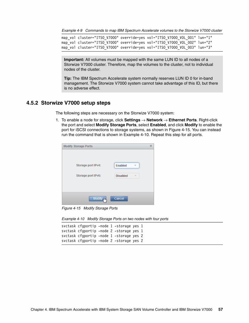
Example 4-9 Commands to map IBM Spectrum Accelerate volumes to the Storwize V7000 cluster
map_vol cluster="ITSO_V7000" override=yes vol="ITSO_V7000_VOL_001" lun="1"map_vol cluster="ITSO_V7000" override=yes vol="ITSO_V7000_VOL_002" lun="2"map_vol cluster="ITSO_V7000" override=yes vol="ITSO_V7000_VOL_003" lun="3"
4.5.2 Storwize V7000 setup steps
The following steps are necessary on the Storwize V7000 system:
1. To enable a node for storage, click Settings → Network → Ethernet Ports. Right-click the port and select Modify Storage Ports, select Enabled, and click Modify to enable the port for iSCSI connections to storage systems, as shown in Figure 4-15. You can instead run the command that is shown in Example 4-10. Repeat this step for all ports.
Figure 4-15 Modify Storage Ports
Example 4-10 Modify Storage Ports on two nodes with four ports
svctask cfgportip -node 1 -storage yes 1svctask cfgportip -node 2 -storage yes 1svctask cfgportip -node 1 -storage yes 2svctask cfgportip -node 2 -storage yes 2
Important: All volumes must be mapped with the same LUN ID to all nodes of a Storwize V7000 cluster. Therefore, map the volumes to the cluster, not to individual nodes of the cluster.
Tip: The IBM Spectrum Accelerate system normally reserves LUN ID 0 for in-band management. The Storwize V7000 system cannot take advantage of this ID, but there is no adverse effect.
Chapter 4. IBM Spectrum Accelerate with IBM System Storage SAN Volume Controller and IBM Storwize V7000 57
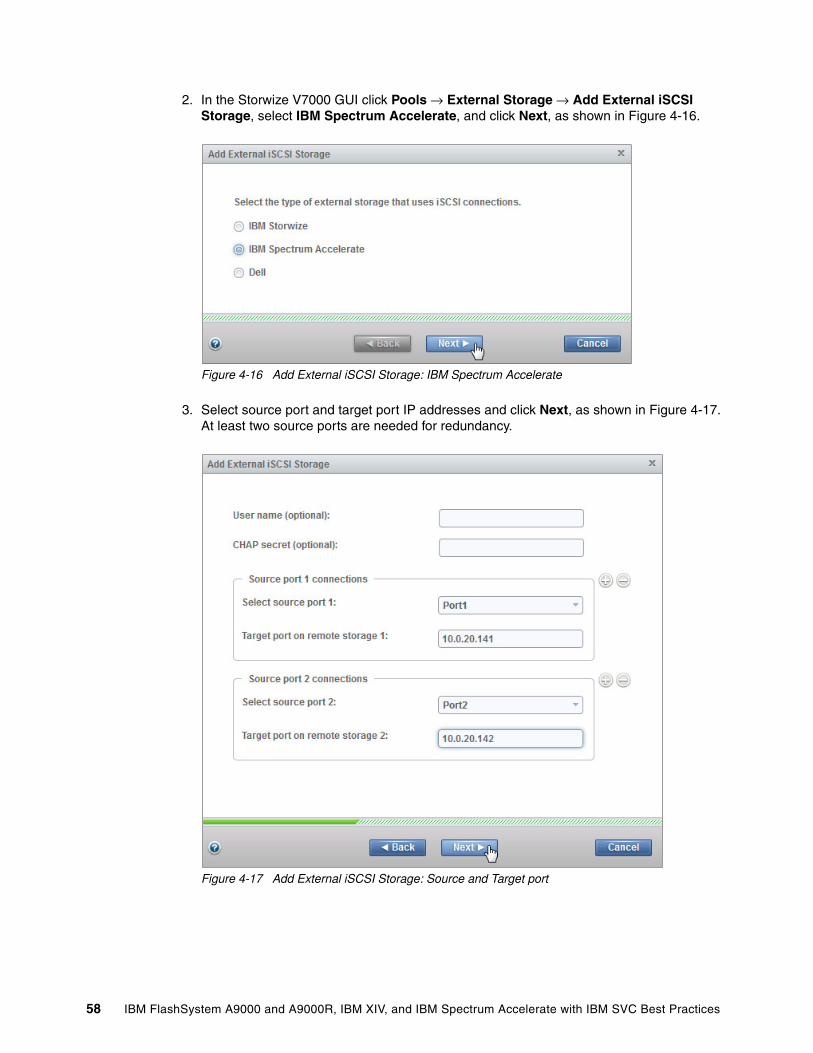
2. In the Storwize V7000 GUI click Pools → External Storage → Add External iSCSI Storage, select IBM Spectrum Accelerate, and click Next, as shown in Figure 4-16.
Figure 4-16 Add External iSCSI Storage: IBM Spectrum Accelerate
3. Select source port and target port IP addresses and click Next, as shown in Figure 4-17. At least two source ports are needed for redundancy.
Figure 4-17 Add External iSCSI Storage: Source and Target port
58 IBM FlashSystem A9000 and A9000R, IBM XIV, and IBM Spectrum Accelerate with IBM SVC Best Practices
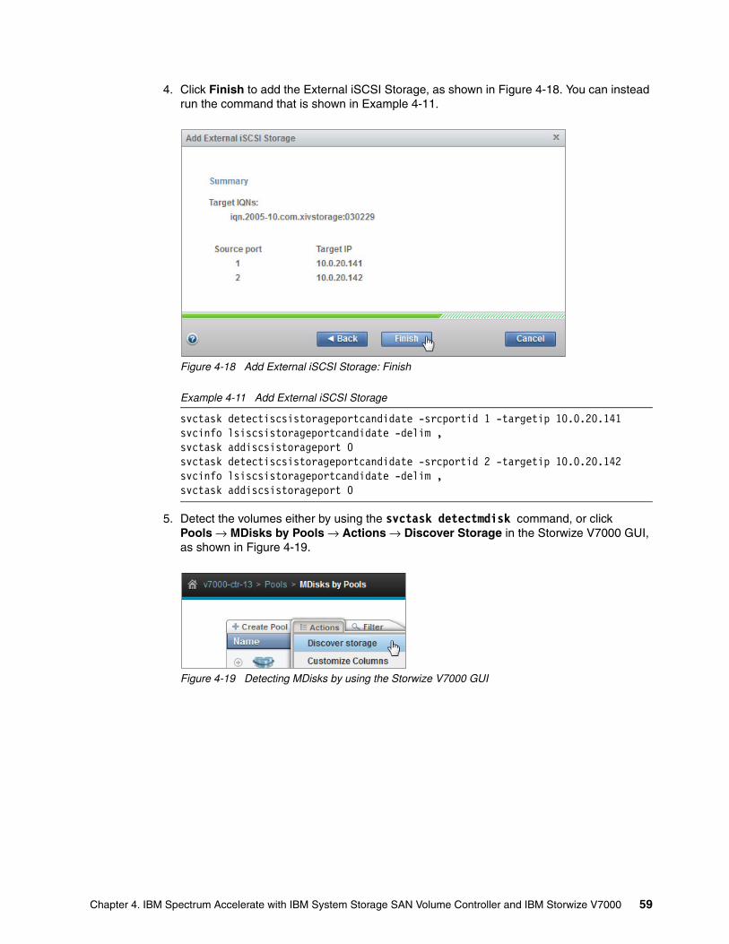
4. Click Finish to add the External iSCSI Storage, as shown in Figure 4-18. You can instead run the command that is shown in Example 4-11.
Figure 4-18 Add External iSCSI Storage: Finish
Example 4-11 Add External iSCSI Storage
svctask detectiscsistorageportcandidate -srcportid 1 -targetip 10.0.20.141svcinfo lsiscsistorageportcandidate -delim ,svctask addiscsistorageport 0svctask detectiscsistorageportcandidate -srcportid 2 -targetip 10.0.20.142svcinfo lsiscsistorageportcandidate -delim ,svctask addiscsistorageport 0
5. Detect the volumes either by using the svctask detectmdisk command, or click Pools → MDisks by Pools → Actions → Discover Storage in the Storwize V7000 GUI, as shown in Figure 4-19.
Figure 4-19 Detecting MDisks by using the Storwize V7000 GUI
Chapter 4. IBM Spectrum Accelerate with IBM System Storage SAN Volume Controller and IBM Storwize V7000 59
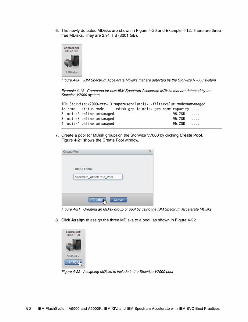
6. The newly detected MDisks are shown in Figure 4-20 and Example 4-12. There are three free MDisks. They are 2.91 TiB (3201 GB).
Figure 4-20 IBM Spectrum Accelerate MDisks that are detected by the Storwize V7000 system
Example 4-12 Command for new IBM Spectrum Accelerate MDisks that are detected by the Storwize V7000 system
IBM_Storwize:v7000-ctr-13:superuser>lsmdisk -filtervalue mode=unmanagedid name status mode mdisk_grp_id mdisk_grp_name capacity ....2 mdisk2 online unmanaged 96.2GB ....3 mdisk3 online unmanaged 96.2GB ....4 mdisk4 online unmanaged 96.2GB ....
7. Create a pool (or MDisk group) on the Storwize V7000 by clicking Create Pool. Figure 4-21 shows the Create Pool window.
Figure 4-21 Creating an MDisk group or pool by using the IBM Spectrum Accelerate MDisks
8. Click Assign to assign the three MDisks to a pool, as shown in Figure 4-22.
Figure 4-22 Assigning MDisks to include in the Storwize V7000 pool
60 IBM FlashSystem A9000 and A9000R, IBM XIV, and IBM Spectrum Accelerate with IBM SVC Best Practices
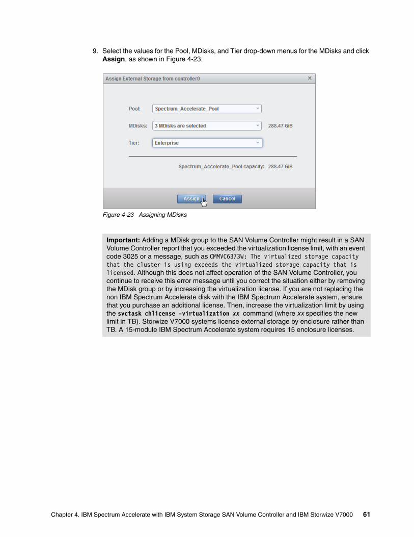
9. Select the values for the Pool, MDisks, and Tier drop-down menus for the MDisks and click Assign, as shown in Figure 4-23.
Figure 4-23 Assigning MDisks
Important: Adding a MDisk group to the SAN Volume Controller might result in a SAN Volume Controller report that you exceeded the virtualization license limit, with an event code 3025 or a message, such as CMMVC6373W: The virtualized storage capacity that the cluster is using exceeds the virtualized storage capacity that is licensed. Although this does not affect operation of the SAN Volume Controller, you continue to receive this error message until you correct the situation either by removing the MDisk group or by increasing the virtualization license. If you are not replacing the non IBM Spectrum Accelerate disk with the IBM Spectrum Accelerate system, ensure that you purchase an additional license. Then, increase the virtualization limit by using the svctask chlicense -virtualization xx command (where xx specifies the new limit in TB). Storwize V7000 systems license external storage by enclosure rather than TB. A 15-module IBM Spectrum Accelerate system requires 15 enclosure licenses.
Chapter 4. IBM Spectrum Accelerate with IBM System Storage SAN Volume Controller and IBM Storwize V7000 61
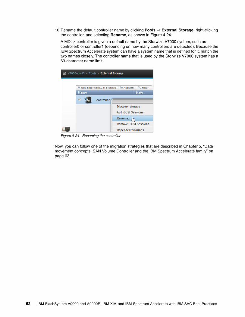
10.Rename the default controller name by clicking Pools → External Storage, right-clicking the controller, and selecting Rename, as shown in Figure 4-24.
A MDisk controller is given a default name by the Storwize V7000 system, such as controller0 or controller1 (depending on how many controllers are detected). Because the IBM Spectrum Accelerate system can have a system name that is defined for it, match the two names closely. The controller name that is used by the Storwize V7000 system has a 63-character name limit.
Figure 4-24 Renaming the controller
Now, you can follow one of the migration strategies that are described in Chapter 5, “Data movement concepts: SAN Volume Controller and the IBM Spectrum Accelerate family” on page 63.
62 IBM FlashSystem A9000 and A9000R, IBM XIV, and IBM Spectrum Accelerate with IBM SVC Best Practices
Chapter 5. Data movement concepts: SAN Volume Controller and the IBM Spectrum Accelerate family
Three possible data movement strategies are described in this chapter. Again, for purposes of brevity, only the XIV system is mentioned, but the strategies hold true for all members of the IBM Spectrum Accelerate family (IBM Spectrum Accelerate system, XIV Gen3 system, and IBM FlashSystem A9000 or IBM FlashSystem A9000R system).
For more information about SAN Volume Controller data movement (migration), see these publications:
� Data Migration to IBM Disk Storage Systems, SG24-7432� Implementing the IBM System Storage SAN Volume Controller with IBM Spectrum
Virtualize V7.8, SG24-7933
5
© Copyright IBM Corp. 2016, 2018. All rights reserved. 63
5.1 Data movement strategies
Three possible data movement strategies are described in this section.
5.1.1 Using SAN Volume Controller migration to move data
You can use standard SAN Volume Controller migration to move volumes from managed disk (MDisk) groups with MDisks from a non-IBM disk controller to MDisk groups with MDisks from another IBM Storage System. This process does not require a host outage, but it does not allow the MDisk group extent size to be changed.
The process requires the following steps:
1. Start with existing volumes (virtual disks (VDisks)) in an existing pool (MDisk group) that uses MDisks from an old storage device. Confirm the extent size of that MDisk group. This is called the source MDisk group.
2. Create volumes on the IBM Spectrum Accelerate family system, and map them to the SAN Volume Controller or Storwize V7000 system by using volumes that are sized according to the principles that are described in 2.4.2, “XIV volume sizes” on page 14, 3.4, “Volume size for IBM FlashSystem A9000 or IBM FlashSystem A9000R with SAN Volume Controller” on page 35, or 4.4, “Volume size for an IBM Spectrum Accelerate system with SAN Volume Controller and Storwize V7000 systems” on page 51.
3. On the SAN Volume Controller or Storwize V7000 system, detect these new MDisks and use them to create an MDisk group. This is called the target MDisk group. The target MDisk group must use the same extent size as the source MDisk group.
4. Migrate each VDisk from the source MDisk group to the target MDisk group.
5. When all of the VDisks are migrated, you can choose to delete the source MDisk group (in preparation for removing the non-IBM storage), which puts the MDisks in this group in Unmanaged mode.
For more information, see 5.2, “Using SAN Volume Controller or Storwize V7000 migration to move data to an IBM Spectrum Accelerate family system” on page 66.
5.1.2 Using VDisk mirroring to move the data
You can use the VDisk copy (mirror) function in SAN Volume Controller firmware Version 4.3 and later to create two copies of the data, one in the source MDisk group and one in the target MDisk group. Remove the VDisk copy in the source MDisk group (pool) and retain the VDisk copy that is present in the target MDisk group. This process does not require a host outage, and it enables you to move to a larger MDisk group extent size. However, it also uses more SAN Volume Controller or Storwize V7000 cluster memory and processor power while the multiple copies are managed by the SAN Volume Controller or Storwize V7000 system.
64 IBM FlashSystem A9000 and A9000R, IBM XIV, and IBM Spectrum Accelerate with IBM SVC Best Practices
The process requires the following steps:
1. Start with existing VDisks in an existing MDisk group. The extent size of that MDisk group is not relevant. This is called the source MDisk group.
2. Create volumes on the storage system, and map them to the SAN Volume Controller or Storwize V7000 system by using volumes that are sized according to the principles that are described in 2.4.2, “XIV volume sizes” on page 14, 3.4, “Volume size for IBM FlashSystem A9000 or IBM FlashSystem A9000R with SAN Volume Controller” on page 35, or 4.4, “Volume size for an IBM Spectrum Accelerate system with SAN Volume Controller and Storwize V7000 systems” on page 51.
3. Detect these XIV MDisks, and create an MDisk group by using an extent size of 1024 MB. This is called the target MDisk group.
4. For each VDisk in the source MDisk group, create a VDisk copy in the target MDisk group.
5. When the two copies are in sync, remove the VDisk copy from the source MDisk group.
6. When all of the VDisks are copied from the source MDisk group to the target MDisk group, either delete the source MDisk group (in preparation for removing the non-IBM storage) or split the VDisk copies and retain the copy from the source MDisk group while necessary.
For more information, see 5.3, “Using VDisk mirroring to move the data” on page 69.
5.1.3 Using SAN Volume Controller migration with Image mode
This migration method is used in the following situations:
� The extent size must be changed, but VDisk mirroring cannot be used. � You want to move the VDisks from one SAN Volume Controller cluster to a different one.� You want to move the data away from the SAN Volume Controller without using
IBM Spectrum Accelerate family migration.
If you take the Image mode VDisk from the SAN Volume Controller or Storwize V7000 system to move it to another system, there will be a host outage, although you can keep it short (potentially only seconds or minutes).
Removing an Image mode VDisk requires the following steps:
1. Start with VDisks in an existing MDisk group. The extent size of this MDisk group might be small (for example, 16 MB). This is the source MDisk group.
2. Create volumes that are the same size (or larger) than the existing VDisks. This might require extra steps because the IBM Spectrum Accelerate family volumes must be created by using 512-byte blocks. Map these specially sized volumes to SAN Volume Controller.
3. Migrate each VDisk to Image mode by using these new volumes (presented as unmanaged MDisks). The new volumes move into the source MDisk group as Image mode MDisks, and the VDisks become Image mode VDisks.
4. Delete all of the Image mode VDisks from the source MDisk group. This is the disruptive part of this process. These are now unmanaged MDisks, but the data on these volumes is intact. You can map these volumes to a different SAN Volume Controller or Storwize V7000 cluster, or you can remove them from the SAN Volume Controller (in that case, the process is complete).
Chapter 5. Data movement concepts: SAN Volume Controller and the IBM Spectrum Accelerate family 65
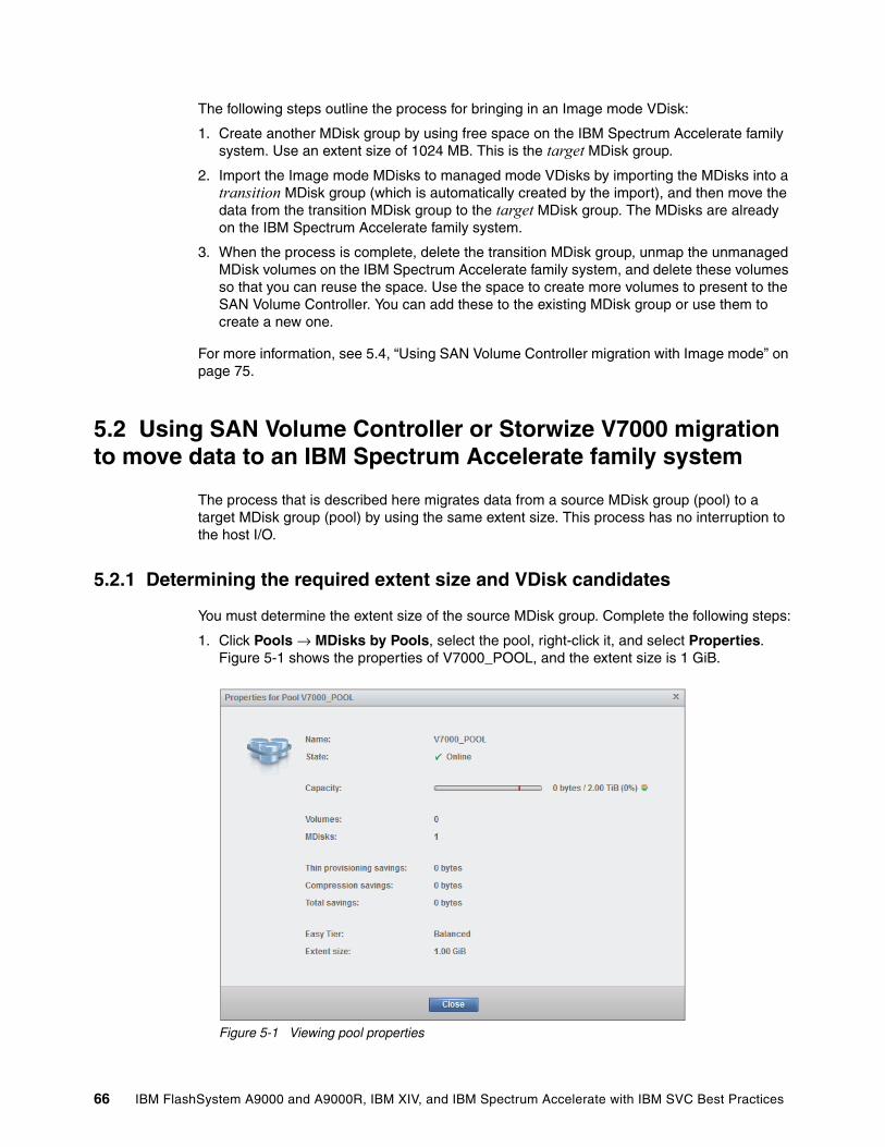
The following steps outline the process for bringing in an Image mode VDisk:
1. Create another MDisk group by using free space on the IBM Spectrum Accelerate family system. Use an extent size of 1024 MB. This is the target MDisk group.
2. Import the Image mode MDisks to managed mode VDisks by importing the MDisks into a transition MDisk group (which is automatically created by the import), and then move the data from the transition MDisk group to the target MDisk group. The MDisks are already on the IBM Spectrum Accelerate family system.
3. When the process is complete, delete the transition MDisk group, unmap the unmanaged MDisk volumes on the IBM Spectrum Accelerate family system, and delete these volumes so that you can reuse the space. Use the space to create more volumes to present to the SAN Volume Controller. You can add these to the existing MDisk group or use them to create a new one.
For more information, see 5.4, “Using SAN Volume Controller migration with Image mode” on page 75.
5.2 Using SAN Volume Controller or Storwize V7000 migration to move data to an IBM Spectrum Accelerate family system
The process that is described here migrates data from a source MDisk group (pool) to a target MDisk group (pool) by using the same extent size. This process has no interruption to the host I/O.
5.2.1 Determining the required extent size and VDisk candidates
You must determine the extent size of the source MDisk group. Complete the following steps:
1. Click Pools → MDisks by Pools, select the pool, right-click it, and select Properties. Figure 5-1 shows the properties of V7000_POOL, and the extent size is 1 GiB.
Figure 5-1 Viewing pool properties
66 IBM FlashSystem A9000 and A9000R, IBM XIV, and IBM Spectrum Accelerate with IBM SVC Best Practices
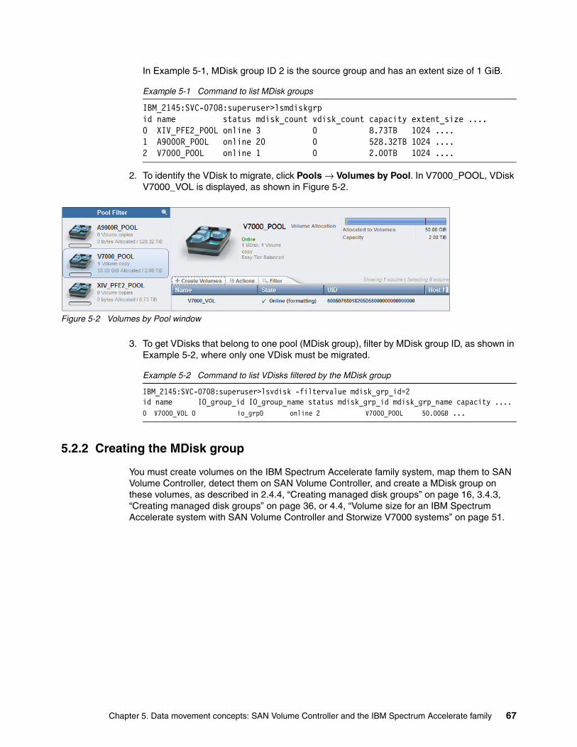
In Example 5-1, MDisk group ID 2 is the source group and has an extent size of 1 GiB.
Example 5-1 Command to list MDisk groups
IBM_2145:SVC-0708:superuser>lsmdiskgrpid name status mdisk_count vdisk_count capacity extent_size ....0 XIV_PFE2_POOL online 3 0 8.73TB 1024 ....1 A9000R_POOL online 20 0 528.32TB 1024 ....2 V7000_POOL online 1 0 2.00TB 1024 ....
2. To identify the VDisk to migrate, click Pools → Volumes by Pool. In V7000_POOL, VDisk V7000_VOL is displayed, as shown in Figure 5-2.
Figure 5-2 Volumes by Pool window
3. To get VDisks that belong to one pool (MDisk group), filter by MDisk group ID, as shown in Example 5-2, where only one VDisk must be migrated.
Example 5-2 Command to list VDisks filtered by the MDisk group
IBM_2145:SVC-0708:superuser>lsvdisk -filtervalue mdisk_grp_id=2id name IO_group_id IO_group_name status mdisk_grp_id mdisk_grp_name capacity ....0 V7000_VOL 0 io_grp0 online 2 V7000_POOL 50.00GB ...
5.2.2 Creating the MDisk group
You must create volumes on the IBM Spectrum Accelerate family system, map them to SAN Volume Controller, detect them on SAN Volume Controller, and create a MDisk group on these volumes, as described in 2.4.4, “Creating managed disk groups” on page 16, 3.4.3, “Creating managed disk groups” on page 36, or 4.4, “Volume size for an IBM Spectrum Accelerate system with SAN Volume Controller and Storwize V7000 systems” on page 51.
Chapter 5. Data movement concepts: SAN Volume Controller and the IBM Spectrum Accelerate family 67

5.2.3 Migration
Complete the following steps:
1. Click Pools → Volumes by Pool, right-click the volume, and select Migrate to Another Pool. Then, select pool A9000R_POOL, as illustrated in Figure 5-3.
Figure 5-3 Migrating the VDisk to another pool
Example 5-3 shows the CLI command that the GUI invokes to migrate the VDisk to another pool.
Example 5-3 Command for migrating a VDisk
migratevdisk -mdiskgrp A9000R_POOL -vdisk V7000_VOL
2. After all VDisks are migrated from the source MDisk group, you can delete the source MDisk group by clicking Pools → MDisks by Pools, right-clicking the pool, and selecting Delete Pool, as shown in Figure 5-4.
Figure 5-4 Delete Pool window
The corresponding CLI command is shown in Example 5-4.
Example 5-4 Command for removing non-XIV MDisks and the MDisk group
rmmdiskgrp -force V7000_POOL
68 IBM FlashSystem A9000 and A9000R, IBM XIV, and IBM Spectrum Accelerate with IBM SVC Best Practices
5.3 Using VDisk mirroring to move the data
This process mirrors data from a source MDisk group to a target MDisk group, which might use a different extent size, with no interruption to the host.
5.3.1 Determining the required extent size and VDisk candidates
The determination of the source MDisk group is shown in Figure 5-1 on page 66 and in Example 5-1 on page 67.
The identification of the VDisks that you are migrating is shown in Figure 5-2 on page 67 and in Example 5-2 on page 67.
5.3.2 Creating the MDisk group
You must create volumes on the IBM Spectrum Accelerate family system, map them to SAN Volume Controller, detect them on SAN Volume Controller, and create a MDisk group on these volumes, as described in 2.4.4, “Creating managed disk groups” on page 16, 3.4.3, “Creating managed disk groups” on page 36, or 4.4, “Volume size for an IBM Spectrum Accelerate system with SAN Volume Controller and Storwize V7000 systems” on page 51.
5.3.3 Setting up the I/O group for mirroring
The I/O group requires reserved memory for mirroring. First, determine whether the memory is reserved. You can do that only by using the CLI. In Example 5-5, the output of the lsiogrp command shows that enough space is assigned for mirroring.
Example 5-5 Checking the I/O group for mirroring
IBM_2145:SVC-0708:superuser>lsiogrp 0id 0name io_grp0node_count 2vdisk_count 1host_count 0flash_copy_total_memory 20.0MBflash_copy_free_memory 20.0MBremote_copy_total_memory 20.0MBremote_copy_free_memory 20.0MBmirroring_total_memory 20.0MBmirroring_free_memory 19.9MBraid_total_memory 40.0MBraid_free_memory 40.0MBmaintenance nocompression_active noaccessible_vdisk_count 1compression_supported yesmax_enclosures 0
Important: Scripts that use VDisk names or IDs are not affected by the use of VDisk migration because the VDisk names and IDs do not change.
Chapter 5. Data movement concepts: SAN Volume Controller and the IBM Spectrum Accelerate family 69
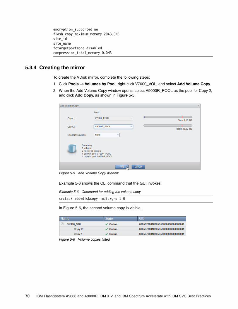
encryption_supported noflash_copy_maximum_memory 2048.0MBsite_idsite_namefctargetportmode disabledcompression_total_memory 0.0MB
5.3.4 Creating the mirror
To create the VDisk mirror, complete the following steps:
1. Click Pools → Volumes by Pool, right-click V7000_VOL, and select Add Volume Copy.
2. When the Add Volume Copy window opens, select A9000R_POOL as the pool for Copy 2, and click Add Copy, as shown in Figure 5-5.
Figure 5-5 Add Volume Copy window
Example 5-6 shows the CLI command that the GUI invokes.
Example 5-6 Command for adding the volume copy
svctask addvdiskcopy -mdiskgrp 1 0
In Figure 5-6, the second volume copy is visible.
Figure 5-6 Volume copies listed
70 IBM FlashSystem A9000 and A9000R, IBM XIV, and IBM Spectrum Accelerate with IBM SVC Best Practices
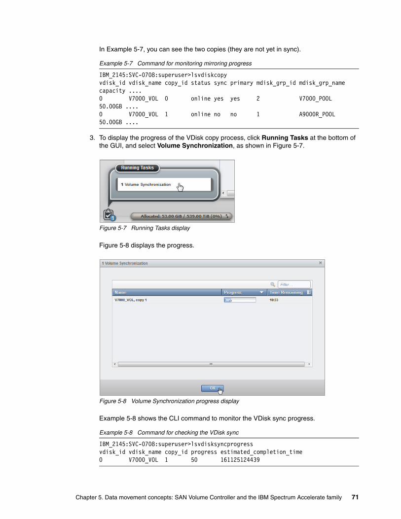
In Example 5-7, you can see the two copies (they are not yet in sync).
Example 5-7 Command for monitoring mirroring progress
IBM_2145:SVC-0708:superuser>lsvdiskcopyvdisk_id vdisk_name copy_id status sync primary mdisk_grp_id mdisk_grp_name capacity ....0 V7000_VOL 0 online yes yes 2 V7000_POOL 50.00GB ....0 V7000_VOL 1 online no no 1 A9000R_POOL 50.00GB ....
3. To display the progress of the VDisk copy process, click Running Tasks at the bottom of the GUI, and select Volume Synchronization, as shown in Figure 5-7.
Figure 5-7 Running Tasks display
Figure 5-8 displays the progress.
Figure 5-8 Volume Synchronization progress display
Example 5-8 shows the CLI command to monitor the VDisk sync progress.
Example 5-8 Command for checking the VDisk sync
IBM_2145:SVC-0708:superuser>lsvdisksyncprogressvdisk_id vdisk_name copy_id progress estimated_completion_time0 V7000_VOL 1 50 161125124439
Chapter 5. Data movement concepts: SAN Volume Controller and the IBM Spectrum Accelerate family 71
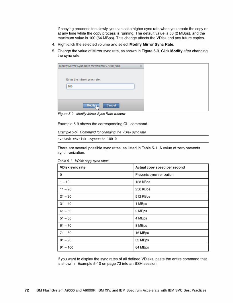
If copying proceeds too slowly, you can set a higher sync rate when you create the copy or at any time while the copy process is running. The default value is 50 (2 MBps), and the maximum value is 100 (64 MBps). This change affects the VDisk and any future copies.
4. Right-click the selected volume and select Modify Mirror Sync Rate.
5. Change the value of Mirror sync rate, as shown in Figure 5-9. Click Modify after changing the sync rate.
Figure 5-9 Modify Mirror Sync Rate window
Example 5-9 shows the corresponding CLI command.
Example 5-9 Command for changing the VDisk sync rate
svctask chvdisk -syncrate 100 0
There are several possible sync rates, as listed in Table 5-1. A value of zero prevents synchronization.
Table 5-1 VDisk copy sync rates
If you want to display the sync rates of all defined VDisks, paste the entire command that is shown in Example 5-10 on page 73 into an SSH session.
VDisk sync rate Actual copy speed per second
0 Prevents synchronization
1 – 10 128 KBps
11 – 20 256 KBps
21 – 30 512 KBps
31 – 40 1 MBps
41 – 50 2 MBps
51 – 60 4 MBps
61 – 70 8 MBps
71 – 80 16 MBps
81 – 90 32 MBps
91 – 100 64 MBps
72 IBM FlashSystem A9000 and A9000R, IBM XIV, and IBM Spectrum Accelerate with IBM SVC Best Practices
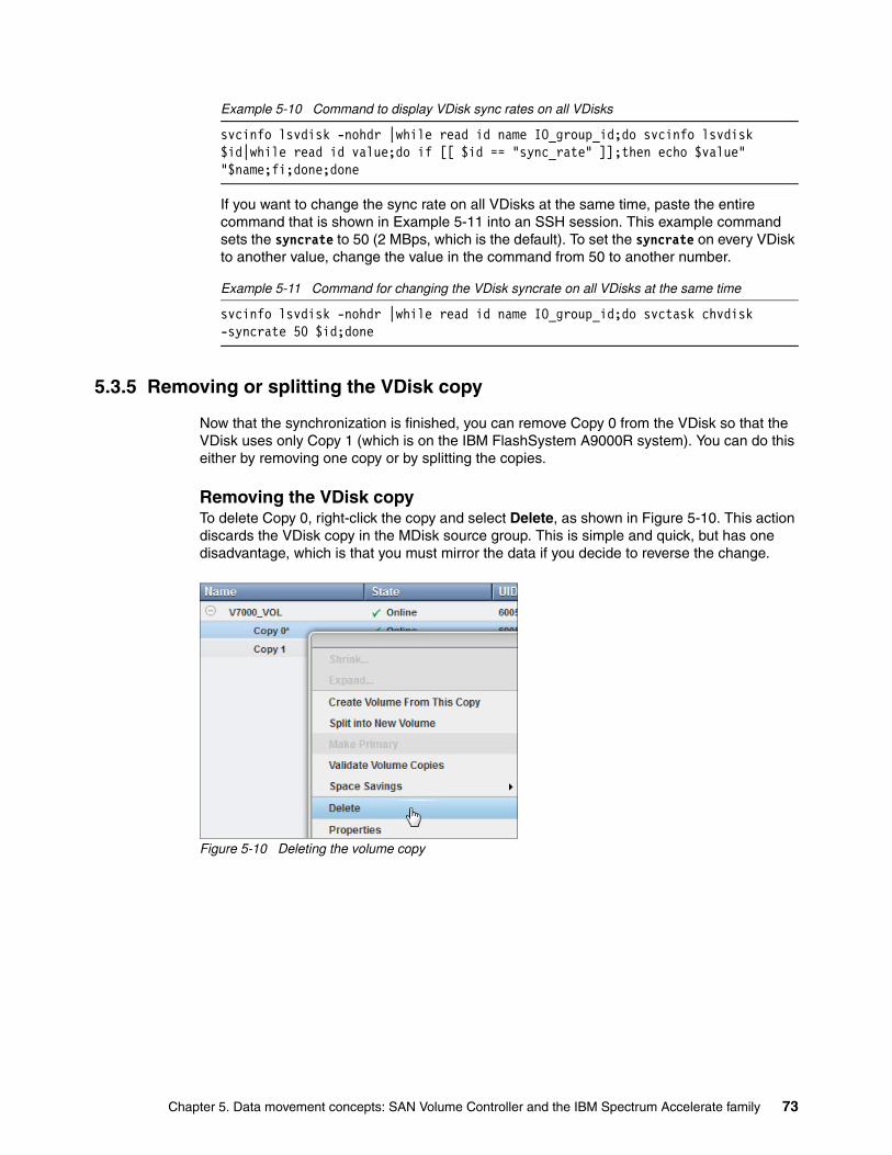
Example 5-10 Command to display VDisk sync rates on all VDisks
svcinfo lsvdisk -nohdr |while read id name IO_group_id;do svcinfo lsvdisk $id|while read id value;do if [[ $id == "sync_rate" ]];then echo $value" "$name;fi;done;done
If you want to change the sync rate on all VDisks at the same time, paste the entire command that is shown in Example 5-11 into an SSH session. This example command sets the syncrate to 50 (2 MBps, which is the default). To set the syncrate on every VDisk to another value, change the value in the command from 50 to another number.
Example 5-11 Command for changing the VDisk syncrate on all VDisks at the same time
svcinfo lsvdisk -nohdr |while read id name IO_group_id;do svctask chvdisk -syncrate 50 $id;done
5.3.5 Removing or splitting the VDisk copy
Now that the synchronization is finished, you can remove Copy 0 from the VDisk so that the VDisk uses only Copy 1 (which is on the IBM FlashSystem A9000R system). You can do this either by removing one copy or by splitting the copies.
Removing the VDisk copyTo delete Copy 0, right-click the copy and select Delete, as shown in Figure 5-10. This action discards the VDisk copy in the MDisk source group. This is simple and quick, but has one disadvantage, which is that you must mirror the data if you decide to reverse the change.
Figure 5-10 Deleting the volume copy
Chapter 5. Data movement concepts: SAN Volume Controller and the IBM Spectrum Accelerate family 73
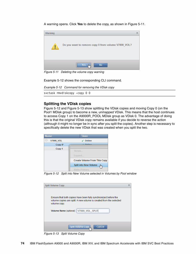
A warning opens. Click Yes to delete the copy, as shown in Figure 5-11.
Figure 5-11 Deleting the volume copy warning
Example 5-12 shows the corresponding CLI command.
Example 5-12 Command for removing the VDisk copy
svctask rmvdiskcopy -copy 0 0
Splitting the VDisk copiesFigure 5-12 and Figure 5-13 show splitting the VDisk copies and moving Copy 0 (on the Pool1 MDisk group) to become a new, unmapped VDisk. This means that the host continues to access Copy 1 on the A9000R_POOL MDisk group as VDisk 0. The advantage of doing this is that the original VDisk copy remains available if you decide to reverse the action (although it might no longer be in sync after you split the copies). Another step is necessary to specifically delete the new VDisk that was created when you split the two.
Figure 5-12 Split into New Volume selected in Volumes by Pool window
Figure 5-13 Split Volume Copy
74 IBM FlashSystem A9000 and A9000R, IBM XIV, and IBM Spectrum Accelerate with IBM SVC Best Practices
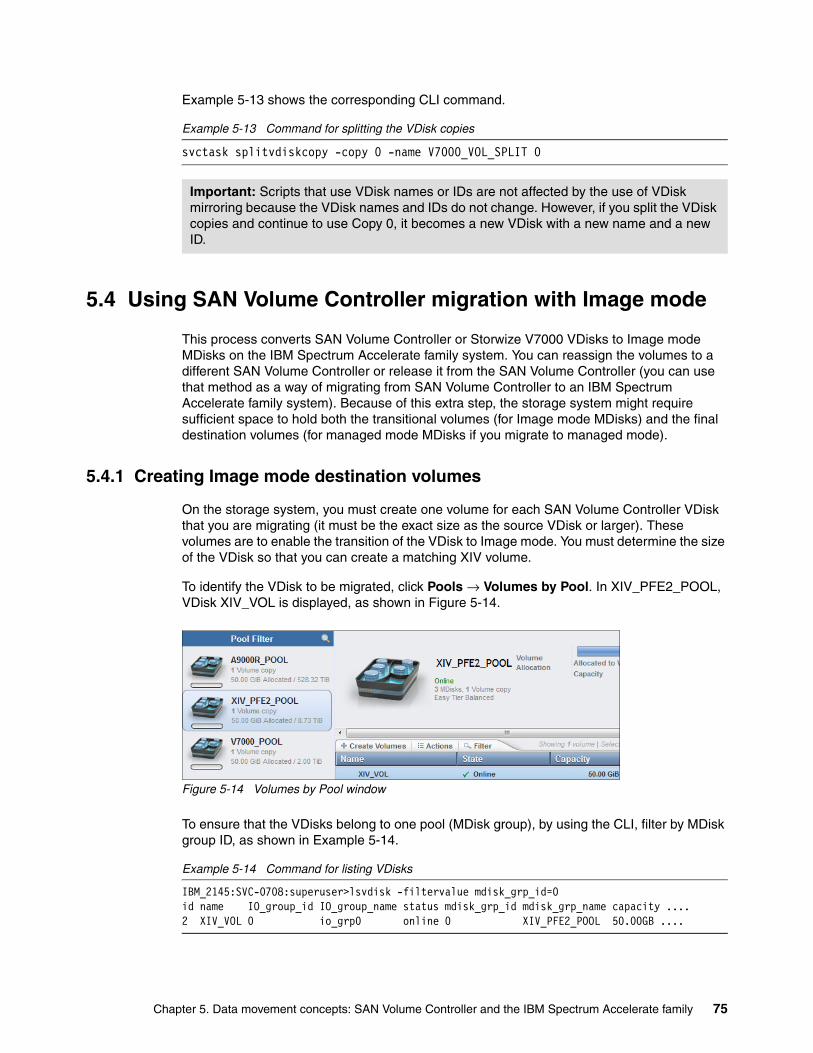
Example 5-13 shows the corresponding CLI command.
Example 5-13 Command for splitting the VDisk copies
svctask splitvdiskcopy -copy 0 -name V7000_VOL_SPLIT 0
5.4 Using SAN Volume Controller migration with Image mode
This process converts SAN Volume Controller or Storwize V7000 VDisks to Image mode MDisks on the IBM Spectrum Accelerate family system. You can reassign the volumes to a different SAN Volume Controller or release it from the SAN Volume Controller (you can use that method as a way of migrating from SAN Volume Controller to an IBM Spectrum Accelerate family system). Because of this extra step, the storage system might require sufficient space to hold both the transitional volumes (for Image mode MDisks) and the final destination volumes (for managed mode MDisks if you migrate to managed mode).
5.4.1 Creating Image mode destination volumes
On the storage system, you must create one volume for each SAN Volume Controller VDisk that you are migrating (it must be the exact size as the source VDisk or larger). These volumes are to enable the transition of the VDisk to Image mode. You must determine the size of the VDisk so that you can create a matching XIV volume.
To identify the VDisk to be migrated, click Pools → Volumes by Pool. In XIV_PFE2_POOL, VDisk XIV_VOL is displayed, as shown in Figure 5-14.
Figure 5-14 Volumes by Pool window
To ensure that the VDisks belong to one pool (MDisk group), by using the CLI, filter by MDisk group ID, as shown in Example 5-14.
Example 5-14 Command for listing VDisks
IBM_2145:SVC-0708:superuser>lsvdisk -filtervalue mdisk_grp_id=0id name IO_group_id IO_group_name status mdisk_grp_id mdisk_grp_name capacity ....2 XIV_VOL 0 io_grp0 online 0 XIV_PFE2_POOL 50.00GB ....
Important: Scripts that use VDisk names or IDs are not affected by the use of VDisk mirroring because the VDisk names and IDs do not change. However, if you split the VDisk copies and continue to use Copy 0, it becomes a new VDisk with a new name and a new ID.
Chapter 5. Data movement concepts: SAN Volume Controller and the IBM Spectrum Accelerate family 75
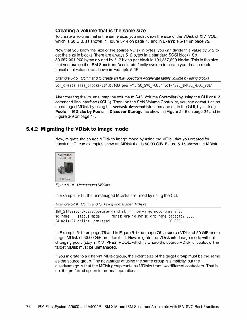
Creating a volume that is the same sizeTo create a volume that is the same size, you must know the size of the VDisk of XIV_VOL, which is 50 GiB, as shown in Figure 5-14 on page 75 and in Example 5-14 on page 75.
Now that you know the size of the source VDisk in bytes, you can divide this value by 512 to get the size in blocks (there are always 512 bytes in a standard SCSI block). So, 53,687,091,200 bytes divided by 512 bytes per block is 104,857,600 blocks. This is the size that you use on the IBM Spectrum Accelerate family system to create your Image mode transitional volume, as shown in Example 5-15.
Example 5-15 Command to create an IBM Spectrum Accelerate family volume by using blocks
vol_create size_blocks=104857600 pool="ITSO_SVC_POOL" vol="SVC_IMAGE_MODE_VOL"
After creating the volume, map the volume to SAN Volume Controller (by using the GUI or XIV command-line interface (XCLI)). Then, on the SAN Volume Controller, you can detect it as an unmanaged MDisk by using the svctask detectmdisk command or, in the GUI, by clicking Pools → MDisks by Pools → Discover Storage, as shown in Figure 2-15 on page 24 and in Figure 3-9 on page 44.
5.4.2 Migrating the VDisk to Image mode
Now, migrate the source VDisk to Image mode by using the MDisk that you created for transition. These examples show an MDisk that is 50.00 GiB. Figure 5-15 shows the MDisk.
Figure 5-15 Unmanaged MDisks
In Example 5-16, the unmanaged MDisks are listed by using the CLI.
Example 5-16 Command for listing unmanaged MDisks
IBM_2145:SVC-0708:superuser>lsmdisk -filtervalue mode=unmanagedid name status mode mdisk_grp_id mdisk_grp_name capacity ....24 mdisk24 online unmanaged 50.0GB ....
In Example 5-14 on page 75 and in Figure 5-14 on page 75, a source VDisk of 50 GiB and a target MDisk of 50.00 GiB are identified. Now, migrate the VDisk into Image mode without changing pools (stay in XIV_PFE2_POOL, which is where the source VDisk is located). The target MDisk must be unmanaged.
If you migrate to a different MDisk group, the extent size of the target group must be the same as the source group. The advantage of using the same group is simplicity, but the disadvantage is that the MDisk group contains MDisks from two different controllers. That is not the preferred option for normal operations.
76 IBM FlashSystem A9000 and A9000R, IBM XIV, and IBM Spectrum Accelerate with IBM SVC Best Practices
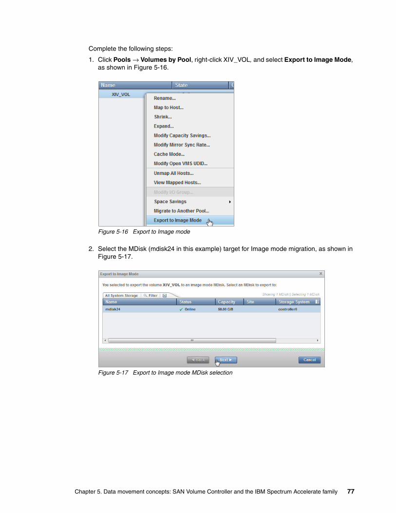
Complete the following steps:
1. Click Pools → Volumes by Pool, right-click XIV_VOL, and select Export to Image Mode, as shown in Figure 5-16.
Figure 5-16 Export to Image mode
2. Select the MDisk (mdisk24 in this example) target for Image mode migration, as shown in Figure 5-17.
Figure 5-17 Export to Image mode MDisk selection
Chapter 5. Data movement concepts: SAN Volume Controller and the IBM Spectrum Accelerate family 77
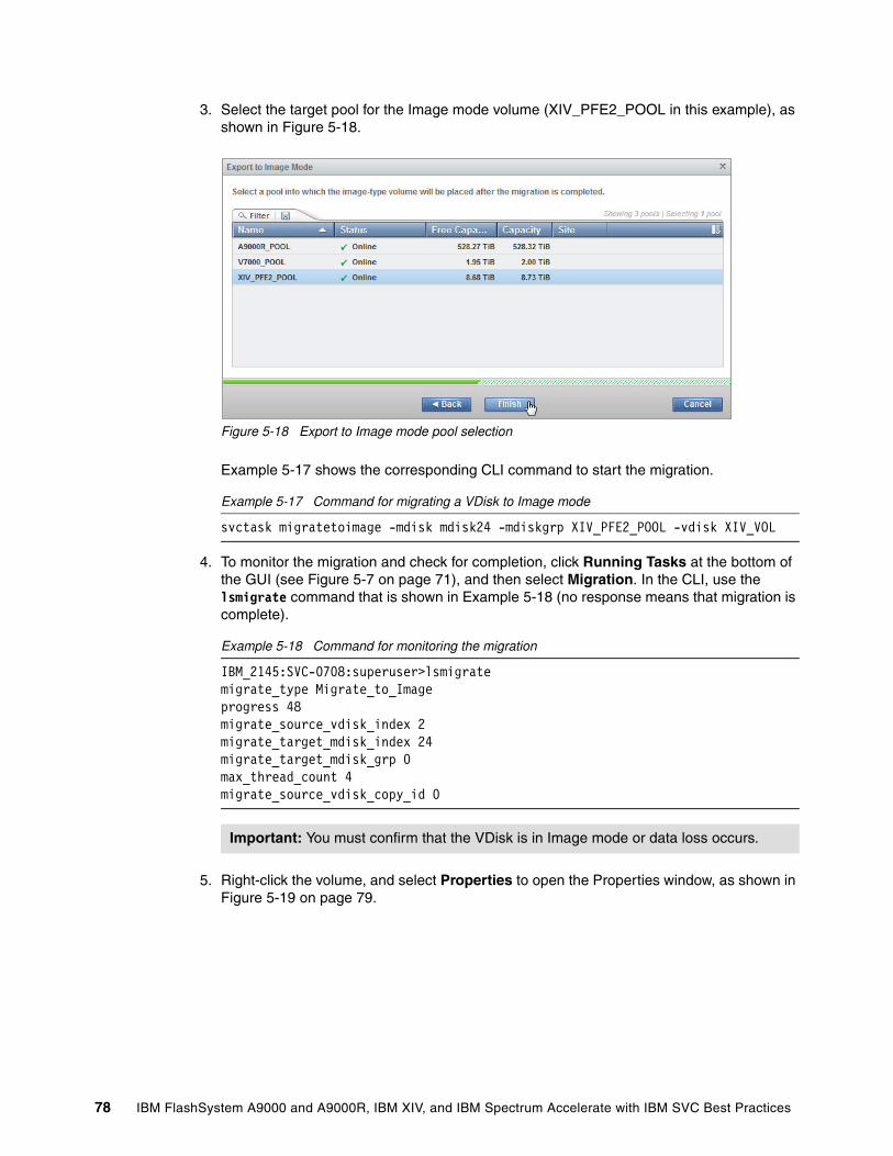
3. Select the target pool for the Image mode volume (XIV_PFE2_POOL in this example), as shown in Figure 5-18.
Figure 5-18 Export to Image mode pool selection
Example 5-17 shows the corresponding CLI command to start the migration.
Example 5-17 Command for migrating a VDisk to Image mode
svctask migratetoimage -mdisk mdisk24 -mdiskgrp XIV_PFE2_POOL -vdisk XIV_VOL
4. To monitor the migration and check for completion, click Running Tasks at the bottom of the GUI (see Figure 5-7 on page 71), and then select Migration. In the CLI, use the lsmigrate command that is shown in Example 5-18 (no response means that migration is complete).
Example 5-18 Command for monitoring the migration
IBM_2145:SVC-0708:superuser>lsmigratemigrate_type Migrate_to_Imageprogress 48migrate_source_vdisk_index 2migrate_target_mdisk_index 24migrate_target_mdisk_grp 0max_thread_count 4migrate_source_vdisk_copy_id 0
5. Right-click the volume, and select Properties to open the Properties window, as shown in Figure 5-19 on page 79.
Important: You must confirm that the VDisk is in Image mode or data loss occurs.
78 IBM FlashSystem A9000 and A9000R, IBM XIV, and IBM Spectrum Accelerate with IBM SVC Best Practices
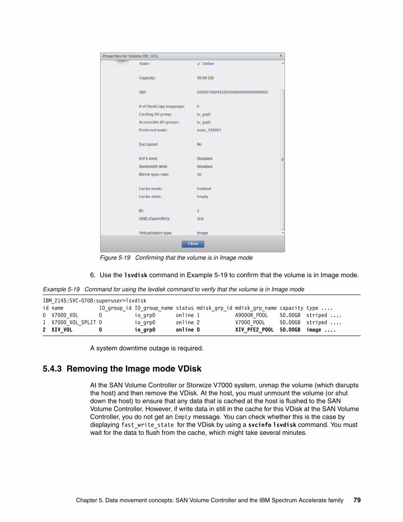
Figure 5-19 Confirming that the volume is in Image mode
6. Use the lsvdisk command in Example 5-19 to confirm that the volume is in Image mode.
Example 5-19 Command for using the lsvdisk command to verify that the volume is in Image mode
IBM_2145:SVC-0708:superuser>lsvdiskid name IO_group_id IO_group_name status mdisk_grp_id mdisk_grp_name capacity type ....0 V7000_VOL 0 io_grp0 online 1 A9000R_POOL 50.00GB striped ....1 V7000_VOL_SPLIT 0 io_grp0 online 2 V7000_POOL 50.00GB striped ....2 XIV_VOL 0 io_grp0 online 0 XIV_PFE2_POOL 50.00GB image ....
A system downtime outage is required.
5.4.3 Removing the Image mode VDisk
At the SAN Volume Controller or Storwize V7000 system, unmap the volume (which disrupts the host) and then remove the VDisk. At the host, you must unmount the volume (or shut down the host) to ensure that any data that is cached at the host is flushed to the SAN Volume Controller. However, if write data in still in the cache for this VDisk at the SAN Volume Controller, you do not get an Empty message. You can check whether this is the case by displaying fast_write_state for the VDisk by using a svcinfo lsvdisk command. You must wait for the data to flush from the cache, which might take several minutes.
Chapter 5. Data movement concepts: SAN Volume Controller and the IBM Spectrum Accelerate family 79
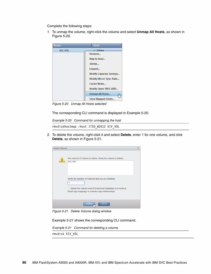
Complete the following steps:
1. To unmap the volume, right-click the volume and select Unmap All Hosts, as shown in Figure 5-20.
Figure 5-20 Unmap All Hosts selected
The corresponding CLI command is displayed in Example 5-20.
Example 5-20 Command for unmapping the host
rmvdiskhostmap -host ITSO_W2K12 XIV_VOL
2. To delete the volume, right-click it and select Delete, enter 1 for one volume, and click Delete, as shown in Figure 5-21.
Figure 5-21 Delete Volume dialog window
Example 5-21 shows the corresponding CLI command.
Example 5-21 Command for deleting a volume
rmvdisk XIV_VOL
80 IBM FlashSystem A9000 and A9000R, IBM XIV, and IBM Spectrum Accelerate with IBM SVC Best Practices
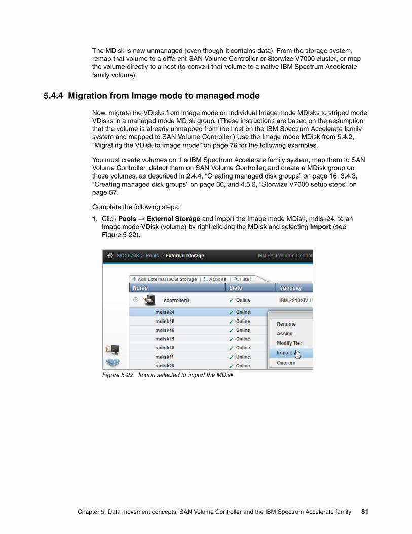
The MDisk is now unmanaged (even though it contains data). From the storage system, remap that volume to a different SAN Volume Controller or Storwize V7000 cluster, or map the volume directly to a host (to convert that volume to a native IBM Spectrum Accelerate family volume).
5.4.4 Migration from Image mode to managed mode
Now, migrate the VDisks from Image mode on individual Image mode MDisks to striped mode VDisks in a managed mode MDisk group. (These instructions are based on the assumption that the volume is already unmapped from the host on the IBM Spectrum Accelerate family system and mapped to SAN Volume Controller.) Use the Image mode MDisk from 5.4.2, “Migrating the VDisk to Image mode” on page 76 for the following examples.
You must create volumes on the IBM Spectrum Accelerate family system, map them to SAN Volume Controller, detect them on SAN Volume Controller, and create a MDisk group on these volumes, as described in 2.4.4, “Creating managed disk groups” on page 16, 3.4.3, “Creating managed disk groups” on page 36, and 4.5.2, “Storwize V7000 setup steps” on page 57.
Complete the following steps:
1. Click Pools → External Storage and import the Image mode MDisk, mdisk24, to an Image mode VDisk (volume) by right-clicking the MDisk and selecting Import (see Figure 5-22).
Figure 5-22 Import selected to import the MDisk
Chapter 5. Data movement concepts: SAN Volume Controller and the IBM Spectrum Accelerate family 81
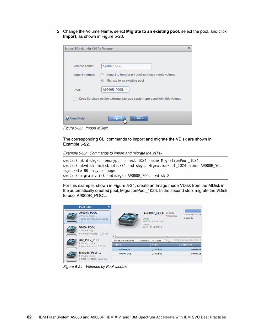
2. Change the Volume Name, select Migrate to an existing pool, select the pool, and click Import, as shown in Figure 5-23.
Figure 5-23 Import MDisk
The corresponding CLI commands to import and migrate the VDisk are shown in Example 5-22.
Example 5-22 Commands to import and migrate the VDisk
svctask mkmdiskgrp -encrypt no -ext 1024 -name MigrationPool_1024svctask mkvdisk -mdisk mdisk24 -mdiskgrp MigrationPool_1024 -name A9000R_VOL -syncrate 80 -vtype imagesvctask migratevdisk -mdiskgrp A9000R_POOL -vdisk 2
For this example, shown in Figure 5-24, create an Image mode VDisk from the MDisk in the automatically created pool, MigrationPool_1024. In the second step, migrate the VDisk to pool A9000R_POOL.
Figure 5-24 Volumes by Pool window
82 IBM FlashSystem A9000 and A9000R, IBM XIV, and IBM Spectrum Accelerate with IBM SVC Best Practices
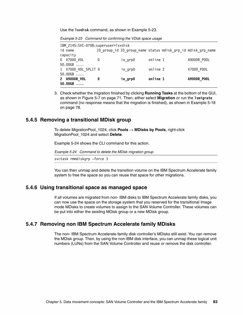
Use the lsvdisk command, as shown in Example 5-23.
Example 5-23 Command for confirming the VDisk space usage
IBM_2145:SVC-0708:superuser>lsvdiskid name IO_group_id IO_group_name status mdisk_grp_id mdisk_grp_name capacity 0 V7000_VOL 0 io_grp0 online 1 A9000R_POOL 50.00GB ....1 V7000_VOL_SPLIT 0 io_grp0 online 2 V7000_POOL 50.00GB ....2 A9000R_VOL 0 io_grp0 online 1 A9000R_POOL 50.00GB ....
3. Check whether the migration finished by clicking Running Tasks at the bottom of the GUI, as shown in Figure 5-7 on page 71. Then, either select Migration or run the lsmigrate command (no response means that the migration is finished), as shown in Example 5-18 on page 78.
5.4.5 Removing a transitional MDisk group
To delete MigrationPool_1024, click Pools → MDisks by Pools, right-click MigrationPool_1024 and select Delete.
Example 5-24 shows the CLI command for this action.
Example 5-24 Command to delete the MDisk migration group
svctask rmmdiskgrp -force 3
You can then unmap and delete the transition volume on the IBM Spectrum Accelerate family system to free the space so you can reuse that space for other migrations.
5.4.6 Using transitional space as managed space
If all volumes are migrated from non- IBM disks to IBM Spectrum Accelerate family disks, you can now use the space on the storage system that you reserved for the transitional Image mode MDisks to create volumes to assign to the SAN Volume Controller. These volumes can be put into either the existing MDisk group or a new MDisk group.
5.4.7 Removing non IBM Spectrum Accelerate family MDisks
The non- IBM Spectrum Accelerate family disk controller’s MDisks still exist. You can remove the MDisk group. Then, by using the non-IBM disk interface, you can unmap these logical unit numbers (LUNs) from the SAN Volume Controller and reuse or remove the disk controller.
Chapter 5. Data movement concepts: SAN Volume Controller and the IBM Spectrum Accelerate family 83
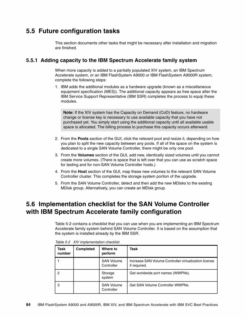
5.5 Future configuration tasks
This section documents other tasks that might be necessary after installation and migration are finished.
5.5.1 Adding capacity to the IBM Spectrum Accelerate family system
When more capacity is added to a partially populated XIV system, an IBM Spectrum Accelerate system, or an IBM FlashSystem A9000 or IBM FlashSystem A9000R system, complete the following steps:
1. IBM adds the additional modules as a hardware upgrade (known as a miscellaneous equipment specification (MES)). The additional capacity appears as free space after the IBM Service Support Representative (IBM SSR) completes the process to equip these modules.
2. From the Pools section of the GUI, click the relevant pool and resize it, depending on how you plan to split the new capacity between any pools. If all of the space on the system is dedicated to a single SAN Volume Controller, there might be only one pool.
3. From the Volumes section of the GUI, add new, identically sized volumes until you cannot create more volumes. (There is space that is left over that you can use as scratch space for testing and for non-SAN Volume Controller hosts.)
4. From the Host section of the GUI, map these new volumes to the relevant SAN Volume Controller cluster. This completes the storage system portion of the upgrade.
5. From the SAN Volume Controller, detect and then add the new MDisks to the existing MDisk group. Alternatively, you can create an MDisk group.
5.6 Implementation checklist for the SAN Volume Controller with IBM Spectrum Accelerate family configuration
Table 5-2 contains a checklist that you can use when you are implementing an IBM Spectrum Accelerate family system behind SAN Volume Controller. It is based on the assumption that the system is installed already by the IBM SSR.
Table 5-2 XIV implementation checklist
Note: If the XIV system has the Capacity on Demand (CoD) feature, no hardware change or license key is necessary to use available capacity that you have not purchased yet. You simply start using the additional capacity until all available usable space is allocated. The billing process to purchase this capacity occurs afterward.
Task number
Completed Where to perform
Task
1 SAN Volume Controller
Increase SAN Volume Controller virtualization license if required.
2 Storage system
Get worldwide port names (WWPNs).
3 SAN Volume Controller
Get SAN Volume Controller WWPNs.
84 IBM FlashSystem A9000 and A9000R, IBM XIV, and IBM Spectrum Accelerate with IBM SVC Best Practices
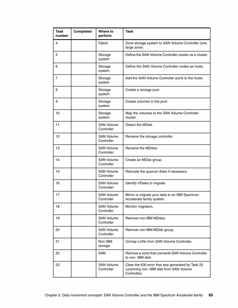
4 Fabric Zone storage system to SAN Volume Controller (one large zone).
5 Storage system
Define the SAN Volume Controller cluster as a cluster.
6 Storage system
Define the SAN Volume Controller nodes as hosts.
7 Storage system
Add the SAN Volume Controller ports to the hosts.
8 Storage system
Create a storage pool.
9 Storage system
Create volumes in the pool.
10 Storage system
Map the volumes to the SAN Volume Controller cluster.
11 SAN Volume Controller
Detect the MDisk.
12 SAN Volume Controller
Rename the storage controller.
13 SAN Volume Controller
Rename the MDisks.
14 SAN Volume Controller
Create an MDisk group.
15 SAN Volume Controller
Relocate the quorum disks if necessary.
16 SAN Volume Controller
Identify VDisks to migrate.
17 SAN Volume Controller
Mirror or migrate your data to an IBM Spectrum Accelerate family system.
18 SAN Volume Controller
Monitor migration.
19 SAN Volume Controller
Remove non-IBM MDisks.
20 SAN Volume Controller
Remove non-IBM MDisk group.
21 Non-IBM storage
Unmap LUNs from SAN Volume Controller.
22 SAN Remove a zone that connects SAN Volume Controller to non- IBM disk.
23 SAN Volume Controller
Clear the 630 error that was generated by Task 22 (unzoning non -IBM disk from SAN Volume Controller).
Task number
Completed Where to perform
Task
Chapter 5. Data movement concepts: SAN Volume Controller and the IBM Spectrum Accelerate family 85

86 IBM FlashSystem A9000 and A9000R, IBM XIV, and IBM Spectrum Accelerate with IBM SVC Best Practices
Related publications
The publications that are listed in this section are considered suitable for a more detailed description of the topics that are covered in this paper.
IBM Redbooks
The following IBM Redbooks publications provide additional information about the topic in this document. Some publications that are referenced in this list might be available in softcopy only.
� Data Migration to IBM Disk Storage Systems, SG24-7432
� IBM FlashSystem A9000 and IBM FlashSystem A9000R Architecture and Implementation, SG24-8345
� IBM Spectrum Accelerate Deployment, Usage, and Maintenance, SG24-8267
� IBM System Storage SAN Volume Controller and Storwize V7000 Best Practices and Performance Guidelines, SG24-7521
� IBM XIV Storage System Architecture and Implementation, SG24-7659
� Implementing the IBM System Storage SAN Volume Controller with IBM Spectrum Virtualize V7.8, SG24-7933
You can search for, view, download, or order these documents and other Redbooks, Redpapers, web docs, drafts, and additional materials, at the following website:
ibm.com/redbooks
Help from IBM
IBM Support and downloads
ibm.com/support
IBM Global Services
ibm.com/services
© Copyright IBM Corp. 2016, 2018. All rights reserved. 87

88 IBM FlashSystem A9000 and A9000R, IBM XIV, and IBM Spectrum Accelerate with IBM SVC Best Practices


ibm.com/redbooks
Printed in U.S.A.
Back cover
ISBN 0738456519
REDP-5408-01
®