iapp - reefer shipreefership.freehostia.com/dls/iapp booklet.pdf · qsms - quality and safety...
TRANSCRIPT

Reefership Marine Services, Limited Vessel Management - San Jose, Costa Rica QSMS - Quality and Safety Management System
IIAAPPPP International Air Pollution Prevention
IINNDDEEXX
Page
1. General Introduction to MARPOL ANNEX VI 2 2. Bunker Delivery Requirements / MARPOL
Specification Form 3
3. Bunker Sampling Procedure 4 4. Packing Sealing and Dispatch of Bunker Sample 5 5. Procedure for Changing FO to Main Engines 7 6. Diagram of Fuel Oil Lines for Main Engines 8 7. Procedure for Changing FO to Auxiliary Engines 9 8. Diagram of Fuel Oil Lines for Auxiliary Engines 10 9. Procedure for Changing FO to Boiler 11 10. Diagram of Fuel Oil Lines for Boiler 12 11. Details of OZONE Depleting Substances on Board 13 12. Handling of OZONE Depleting Substances 13
MM..VV.. DDoollee CCaalliiffoorrnniiaa

QSMS - Quality and Safety Management System by Capt. Pawanexh Kohli
2 of 13
M.V. Dole California
11.. GGEENNEERRAALL From May 19th 2005 the first piece of MARPOL Annex VI came into force. Essentially this first piece of legislation limits the Sulfur level of bunkers used on board ships to 4.5%. As from this same date, Suppliers have a duty to provide the ship with a Bunker Delivery receipt containing the following information:
1. Name & IMO number of Receiving Ship 2. Bunker Port 3. Date of commencement of delivery 4. Name, Address & Telephone number of Supplier 5. Product Name 6. Quantity – Metric Tons 7. Density @ 15°C 8. Sulfur content (% m/m) 9. A Declaration signed and certified by the fuel Supplier’s representative that the fuel oil
supplied is in conformity with the MARPOL Regulations (see Sample on next page) Test methods for Density & Sulfur are to be ISO 3675 & ISO 8754. The Supplier must take a representative sample of the bunkers supplied; the MARPOL recommendation is that this sample be taken by continuous drip at the ship’s receiving manifold. This sample needs to be signed and sealed by the Supplier and be marked “MARPOL”. The seal number on this sample should be written on the Bunker Receipt. The MARPOL sample must be retained on board the ship with the Bunker Delivery receipt for at least one year. This sample must not be used for testing. It should only be released to an officer representing a Port or State authority, if requested. If this sample or any Bunker receipt is handed over to such a person, the Captain must obtain a signature for custody transfer. The new requirements do not change the situation regarding the taking of “commercial” samples. Ship’s staff should continue to take samples at their receiving manifold. One sample is sent for testing, one is issued to the Supplier and the other retained on board for future testing if required. It is also possible that the Supplier may issue another sample to the ship, in the usual manner. This (not the MARPOL sample) may be used for testing in case of any quality dispute. It is not recommend that the Ship’s staff take charge of obtaining, labeling, and sealing the MARPOL sample; this is the duty of the Supplier. If the MARPOL sample is taken by Ship's staff and later found to be not representative, the Supplier could blame the Ship and a complicated legal dispute could arise. However, we have included the additional bottle for the MARPOL sample to assist the process if the Supplier does not have a proper bottle. According to MARPOL Annex VI, the Supplier has to provide an extra bottle of the fuel supplied for the C/E to keep onboard the vessel. This is the dedicated MARPOL sample and should be kept onboard under safe custody for a minimum of one year. The volume of the bottle should be at least 400 ml. The bottle label should contain the following information:
QSMS - Quality and Safety Management System by Capt. Pawanexh Kohli
3 of 13
M.V. Dole California
1) Location at which and the method by which, the sample was taken 2) Bunker Date 3) Bunker Port 4) Name of Bunker Barge / bunker installation 5) Name and IMO no. of the vessel 6) Supplier Name 7) Name and Signatures of Supplier's representative and Ship's representative 8) Details of Seal Identification 9) Bunker Grade
Although it is the Supplier’s responsibility to take this sample and provide this extra bottle, vessel is also able to provide an extra bottle, should the Supplier not have a proper bottle. The responsibility for the Supplier's MARPOL sample rests with the Supplier. If ship-staff draw the sample and give it to the Supplier, he could very well say that it is not his sample. Please recognize this important intent of the MARPOL VI regulation. To ensure Compliance with MARPOL specifications, the vessel strictly adheres to the following –
• A defined sample collecting procedure • A defined oil sample dispatch procedure. • Proper Labeling and dispatch & storing of oil samples
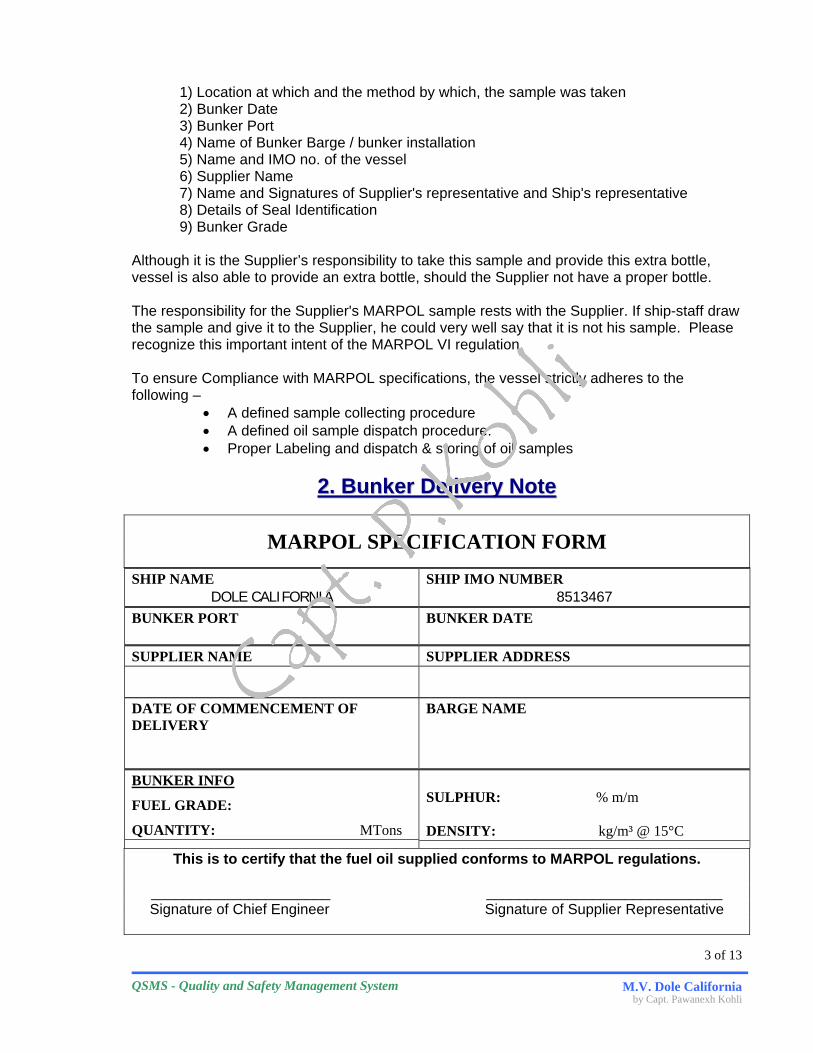
22.. BBuunnkkeerr DDeelliivveerryy NNoottee
MARPOL SPECIFICATION FORM
SHIP NAME DOLE CALIFORNIA
SHIP IMO NUMBER 8513467
BUNKER PORT
BUNKER DATE
SUPPLIER NAME
SUPPLIER ADDRESS
DATE OF COMMENCEMENT OF DELIVERY
BARGE NAME
BUNKER INFO
FUEL GRADE:
QUANTITY: MTons
SULPHUR: % m/m DENSITY: kg/m³ @ 15°C
This is to certify that the fuel oil supplied conforms to MARPOL regulations.
______________________ _____________________________ Signature of Chief Engineer Signature of Supplier Representative

QSMS - Quality and Safety Management System by Capt. Pawanexh Kohli
4 of 13
M.V. Dole California
33.. SSAAMMPPLLIINNGG PPRROOCCEEDDUURREE
Sampling is carried out by the continuous drip method throughout the period of fuel transfer. At the beginning of bunkering; 4 to 5 liters of fuel are flushed into a waste container by opening the needle valve completely. The needle valve on the probe is adjusted to the appropriate setting to ensure collection of a representative sample.
The sample is collected in a thoroughly clean, dry disposable plastic cubitainer, which supported by a rigid outer box. A 4-liter container is recommended for this purpose. minimum of 1.5 liters and a maximum of 3 liters of sample are to be collected during bunkering. The neck of the cubitainer is recessed to minimize storage space. By pulling firmly on the cubitainer neck, the threaded portion may be extended to allow connection to the brass cap of the sampler. The valve and the top of the cubitainer are enclosed the security mechanism and locked. See illustration.
In case of any substantial change in the rate of fuel flow, the valve may have to be adjusted to compensate for the change in flow rate.
When bunkering is completed, the protective casing is unlocked and opened. If the line fuel is being sucked by the shore facility shut the needle valve to prevent cubitainer contents from getting sucked back. The needle valve is opened fully to allow the oil in the sampler to drain into the cubitainer. The cubitainer is removed and capped. It is then shaken vigorously for a minimum of 30 seconds to ensure homogeneity of the sample.
The contents of the cubitainer may then be poured into sample bottles. When filling the bottles, the sample should be distributed evenly among the sample bottles in three or four passes, filling each bottle partially with each pass. Each sample bottle is then sealed and labeled for identification. One bottle is sent to the VLC laboratory for testing. One bottle is given to the supplier or his representative. One bottle is to be stored in a safe place in case of any contingency and for future reference.

QSMS - Quality and Safety Management System by Capt. Pawanexh Kohli
5 of 13
M.V. Dole California

QSMS - Quality and Safety Management System by Capt. Pawanexh Kohli
6 of 13
M.V. Dole California
LLaabbeelliinngg ooff FFOO SSaammpplleess
VISWA LAB OIL SAMPLE FOR ANALYSIS
Vessel Owner
Vessel Name
IMO No.
Port / Location
Sampling Date / Grade
Supplier
Barge / Terminal
Sample Pt. / Method
Seal # Qty Mtons
Remarks
Vessel Rep Supplier Rep
Name: Name:
Sign Sign

QSMS - Quality and Safety Management System by Capt. Pawanexh Kohli
7 of 13
M.V. Dole California
PPrroocceedduurree ffoorr CChhaannggiinngg FFOO ttoo MMaaiinn EEnnggiinneess
1. Close the Steam inlet and return valves to the M/E Fuel oil heaters.
2. Let the temperature in the circuit fall down to about 100 degrees Celsius. This will take approximately 45 minutes.
3. Start reducing the ME RPM to 85.
4. When at 85 RPM, change over the Change over (3 Way) inlet valve (between IFO service tank and MDO service tank) to MDO position.
5. Return line to be kept to Mixing tank for proper mixing and subsequent filling with MDO.
6. Check the FO return line to confirm that line contains MDO.
For faster change over, the return line to the Mixing tank can be diverted to the HFO Service tank. Though, once MDO is confirmed in the return line, this should then be re-routed to return to the Mixing tank.
Other approximate parameters taken into account are:
• Volume of oil in Pipelines: 160 Liters. • Volume of oil in pumps & other accessories: 40 Liters • Fuel consumption: 1.3 MT/Hour • Time taken for c/o: 90 Minutes)
Note: The values quoted in this procedure are when changing over from IFO 500
Refer to Line diagram on next Page.

QSMS - Quality and Safety Management System by Capt. Pawanexh Kohli
8 of 13
M.V. Dole California
Heater # 1
Heater # 2
I.F.O. Service Tank
M.D.O. Service Tank
Filter
Flow Meter
MAIN
ENGINE
Sunil Saini
pKohli-DFFI
DAMPER
Return Tank Hot
Filters
F.O. MixingTank
Drawing by Capt. Pawanexh Kohli
M.E. Fuel Oil Line Diagram M.V. Dole California
M/E Feed Pumps
F.O. Booster Pumps
Quick Closing Valve
Quick Closing Valve
Change Over Valve
Bypas
Pressure Adjusting
Valve
Viscometer
Ventv/v
to Service Tank
3 way Valve

QSMS - Quality and Safety Management System by Capt. Pawanexh Kohli
9 of 13
M.V. Dole California
PPrroocceedduurree ffoorr CChhaannggiinngg FFOO ttoo AAuuxxiilliiaarryy EEnnggiinneess
AA. When required to change over FO to a particular Auxiliary Engine:
a. Confirm the particular AE’s on which FO requires to be changed over.
b. Ensure that the MDO feed pumps are running.
c. On this (or each) particular AE, the change over can be affected by using the individual change over valves on its inlet and return lines.
Note: In case of blackout/initial start up the Boiler MDO tank can be used to have gravity head
pressure in the MDO lines.
BB. When required to change over FO to all Auxiliary Engines:
a. Close the steam inlet and return valves to the AE Fuel oil heaters.
b. Let the temperature in the circuit fall down to about 100 degrees Celsius. (approximately 120 minutes)
c. Change over the 3 way inlet valve (between IFO service tank and MDO service tank) to MDO position.
d. Run the AE’s on load for at least 90 minutes.
e. Check the return lines to confirm that the line contains MDO.
f. Return line should be set to return FO to the mixing tank.
Approximate parameters taken into account are:
• Volume of oil in pipelines: 400 Liters. • Volume of oil in pumps & other accessories: 50 Liters. • Time taken for complete c/o: 2 hours.
Refer to Line diagram on next Page.

QSMS - Quality and Safety Management System by Capt. Pawanexh Kohli
10 of 13
M.V. Dole California
3-Way C/O
Valve
IndividualC/O valves
Viscotherm
Quick Closing Valve
Quick Closing Valve
Feed Pumps
D.O. Feed P/ps
For Emergency
Use
MDO Return Line
Recirculation
Pressure Adj.Valve
A.E. Fuel Oil Line Diagram
M.V. Dole California
Filter
Hot Filter
AE # 1
AE # 2
AE # 3
AE # 4
AE # 5
AE # 6
MixingTank
Flow Mete
r
I.F.O. Service Tank
M.D.O. Service Tank
Boiler MDO Tank
Filter
Filter
Heaters 1 & 2
Booster Pumps
Drawing by Capt. Pawanexh Kohli
Filters
QSMS - Quality and Safety Management System by Capt. Pawanexh Kohli
11 of 13
M.V. Dole California
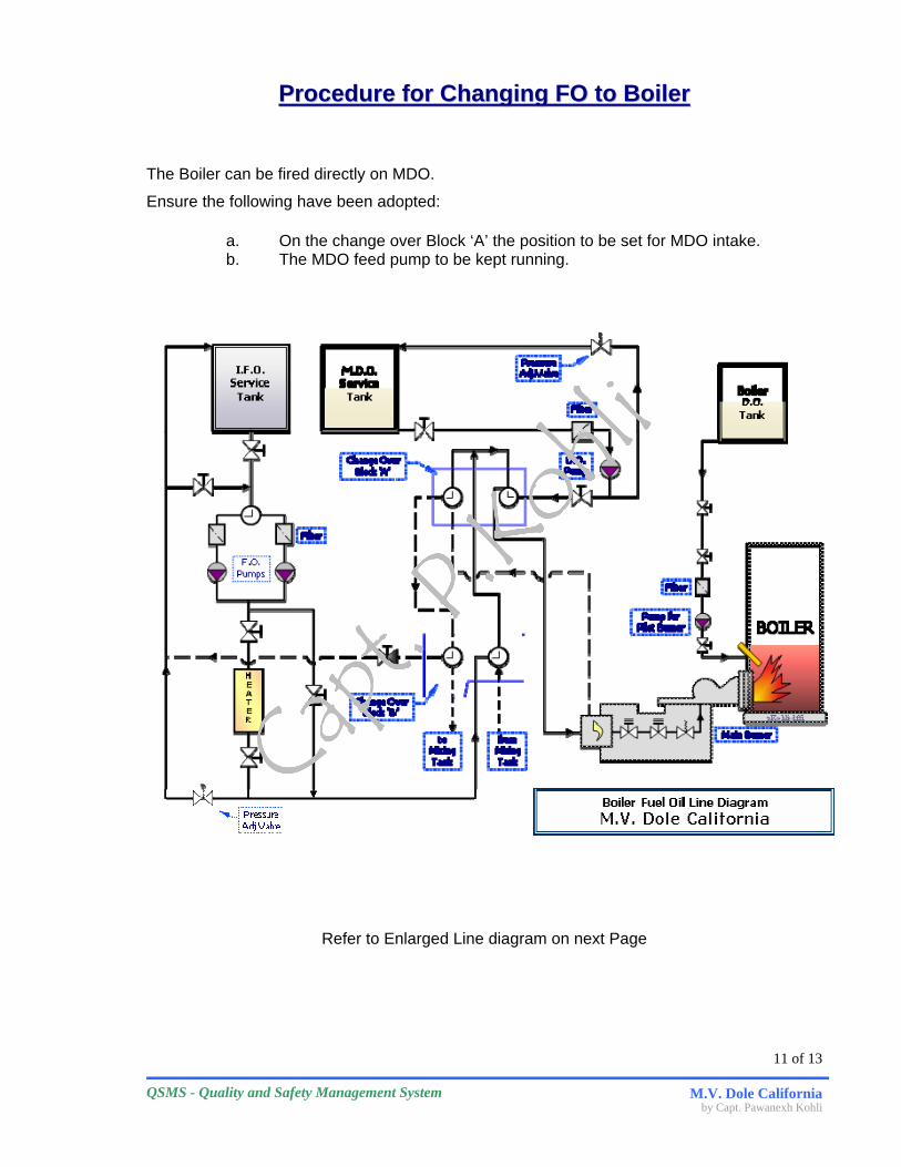
PPrroocceedduurree ffoorr CChhaannggiinngg FFOO ttoo BBooiilleerr
The Boiler can be fired directly on MDO.
Ensure the following have been adopted:
a. On the change over Block ‘A’ the position to be set for MDO intake. b. The MDO feed pump to be kept running.
Refer to Enlarged Line diagram on next Page

QSMS - Quality and Safety Management System by Capt. Pawanexh Kohli
12 of 13
M.V. Dole California
I.F.O. Service
Tank
H E A T E R
Boiler D.O. Tank
M.D.O. Service
Tank
BOILER
pKohli-dffi
Boiler Fuel Oil Line DiagramM.V. Dole California
from MixingTank
to MixingTank
Pump for Pilot Burner
F.O. Pumps
Pressure Adj.Valve
Pressure Adj.Valve
D.O. Pump
Filter
Filter
Filter
Change OverBlock ‘B’
Change OverBlock ‘A’
Main Burner

QSMS - Quality and Safety Management System by Capt. Pawanexh Kohli
13 of 13
M.V. Dole California
DDeettaaiillss ooff OOZZOONNEE DDeepplleettiinngg SSuubbssttaanncceess oonn BBooaarrdd
• UTILITY – Refrigerants are the only substances specified as Ozone depleting on board the vessel. The following list details the services using ozone depleting substances (refrigerants).
# Service Location Model Refrigerant Used Quantity of Refrigerant
Used
1. Accommodation AC Plant 1 E/R 1st Flat Stbd For’d CVC 077 R22 (HCFC 22) 70.0 Kg
2. Accommodation AC Plant 2 E/R 1st Flat Stbd For’d CVC 077 R22 (HCFC 22) 70.0 Kg
3. ECR AC Plant 1 Main Deck Port aft of ECR 4 CC 68 R22 (HCFC 22) -
4. ECR AC Plant 2 Main Deck Port aft of ECR 4 CC 68 R22 (HCFC 22) -
5. Provision Room Plant 1 E/R 1st Flat Stbd For’d 41VS/M R22 (HCFC 22) 19.1 Kg
6. Provision Room Plant 2 E/R 1st Flat Stbd For’d 41VS/M R22 (HCFC 22) 19.1 Kg
TOTAL Refrigerant in Use on Board: 178.2 Kg
• REFRIGERANT STORE (Recharging bottles) o Refrigerant Stored at: Freon Storage Room o Located At: Main Deck Port aft of Central Store o Quantity Stored: 5 bottles x 57 kg each
• REFRIGERANT RECOVERY EQUIPMENT Equipment to recover refrigerant has been installed on board. Details are as follows:
o Manufacturer: Unitor o Capacity: 55.8 Ltrs.
HHaannddlliinngg OOff OOzzoonnee DDeepplleettiinngg SSuubbssttaanncceess o No Ozone depleting substance is allowed to escape to atmosphere. o Refrigerant Recovery Equipment is used to recover refrigerant from services as
and when required. o If refrigerant is not contaminated, it is reused to recharge. o When refrigerant is contaminated, it is landed for authorized disposal. o Operating Manual of the recovery equipment is attached.