i o ----. 0:':' --1 fjvi~ransmi~ters i · initions relating to law enforcement...
TRANSCRIPT
.~---,----------~'~-~~'---- -, I
\.1
,
This microfiche was produced from documents ,:received for inclusion in the NCJRS data base. Since NCJRSl: can~ot exercise
control over the physical condition' of the do~ume~ts submitted, the individual frame quality will ury. The resolution chart on
this frame maybe used to evaluate the document quality.
· ----. I 0:':' -~:5 --1 11II1§1§· 1§ li.i ~III~ t.\ ' 1111 W I
W 1M .. 1 tt£ ~ r'
II lZl~ d • _ ffibt: \]
= l1 111111.25 111111.4 111111.6 f1
MICROCOPY RESOLUTION rEST CHART NATIONAL BUR~U OF :>Tj.NPARDS-J96H
!.1
If
It lL ~\l~~~. T'.~t. ' ~
__ ~"''-'_~''''' •.• n' ..... :"" •• _,. "~ ......... ,,,",-,,~.~.., __ ,, 4,;--" ~ ~,-_ ... , ,< .. .--. .-.. ........ -.., ...... ~~,<-
Microfilminl procedures used 'to 'crute this fiche comply with
the st~ndards set· forth, in 41CFR 101·11.504 '
Points of view or opinions stated in thisducument are those of ' the author(s! and do not'npresent the official position or polici,es of the U .. S. De~aJtment of Jutice.
. U.S. DEPARTMENT OF JUSTICE .. , LA,WENFORCEMENT ASSISTANC~:;ADrnN'ISTRA tlON NATIONAL CRtMINAL .JUSTlCt,:REfERENCF. SERV1:CE , ' " WASHINGTON, D.C.2053r)r.li.·:~c.;>-' ' ,
~ .P:, ,,::'1,
. ~;
" :,;\'
, \I
'" /1 ~ , 0. LAW ENFORCENlENTS;TANDARDS PROGRAM &
'," . '-",'~,,' .11" \\. (}, , " ~\ " f~ ,"" ,', II( . 1"
{;. i . ;/ , '
Q o
l:~ , , ~,
PERSONAL/PORTABLE .. FJVI~RANSMI~TERS c
'0
// I "~~
I 'I -//
'STANDARD
":',Tsqrn nm ',', " ..... '.'.'."',
' '
." .
" '
'-n ('$ ·0 u.s .. DEPARTMENT OF JUSTICE
law Enforcement Assistance Administrati~on . National Institute of ,Law Eriforcementand 6CriminaiJustice
, U' .-.".. .. ' "", "
()
(j
o
;J
If you have issues viewing or accessing this file contact us at NCJRS.gov.
/i (!
o
Q
"
"
()
Library of Congress Cataloging in Publication Data
National Institute of Law Enforcement and Criminal Justice. NILECr standard for personal/portable FM transmitters. At head of title: Law Enforcement Standards Program. "NILECJ-STD-0203 .00." Bibliography: p. 17 1. Radio frequency modulation...,-Transmitters and transmis
sion-Standards-United States. 2. Police communication systemsStandards-United States. 1. Title. n. Title: Personal/portable PM transmitters. III. Title: Law Enforcement Standards Program.
TK6562':F2N37 1975b 621.3841'52'0973 75-2252
:,:
:,
LAW ENFORCEMENT STANDARDS PROGRAM
NILECJ STANDARD FOR
PERSONAL/PORTABLE FM TRANSMITTERS
A Voluntary National Standard Promulgated by the National Institute of Law Enforcement and Criminal Justice.
OCTOBER 1974
U.S. DEPARTMENT OF JUSTICE law Enforcement Assistance Administration
'National Institute of Law Enforcement and Criminal . Justice
c, . ;,
I
!
/: "
<>
LAW ENFORCEMENT ASSISTANCE ADMINISTRATION
Richard W. Velde, Administrator L·
Charles R~ Work, Deputy Administ.rator
..
\1 \
NATIONAL INSTITUTE OF .,LAWEN FORCEM ENT AND CRIMINAL'JUSTICE
Gerald M. Caplan, Director
o
ACKNOWLEDGMENTS.
((
o
This standard was formulated by the Law 'Enforcement StandardsLaboratory of the. National Bux:eau of Standards under the di.rection of Marshall J. Treado, ]>rogram Manager for Communications Systems, and Jacob J .. DiamO'nd, Chief of LESL Acknowledgment is given to previous work.in this,field by the AssociatedPhblic.safety Communications Officers, IIl~.;the· Institute.of'l'Electrical and Electronics Engineers, Inc.; the Electroniclndustries Association; the American Nation~ Standards Ins!!tute;and .the International Electrotechnical GOInmission. f.l . ,<> ',~ ~" . .i!; ..
For. sale by the SuperinteJ;1dentof Documents, U.S.GoV~mnleIifrrinting Office , Washlngton,D.C; 29402 -Price 71) cents""",
Q
Stock Number 027~0(H)0293 C, (j
A ) } ( I· t"._,
, .
. .;~
t ,"::3-1,
i!l I'
/.( C\
,,,\~~ NILECJ Standard
. for Person'all PortableFM Transmitters
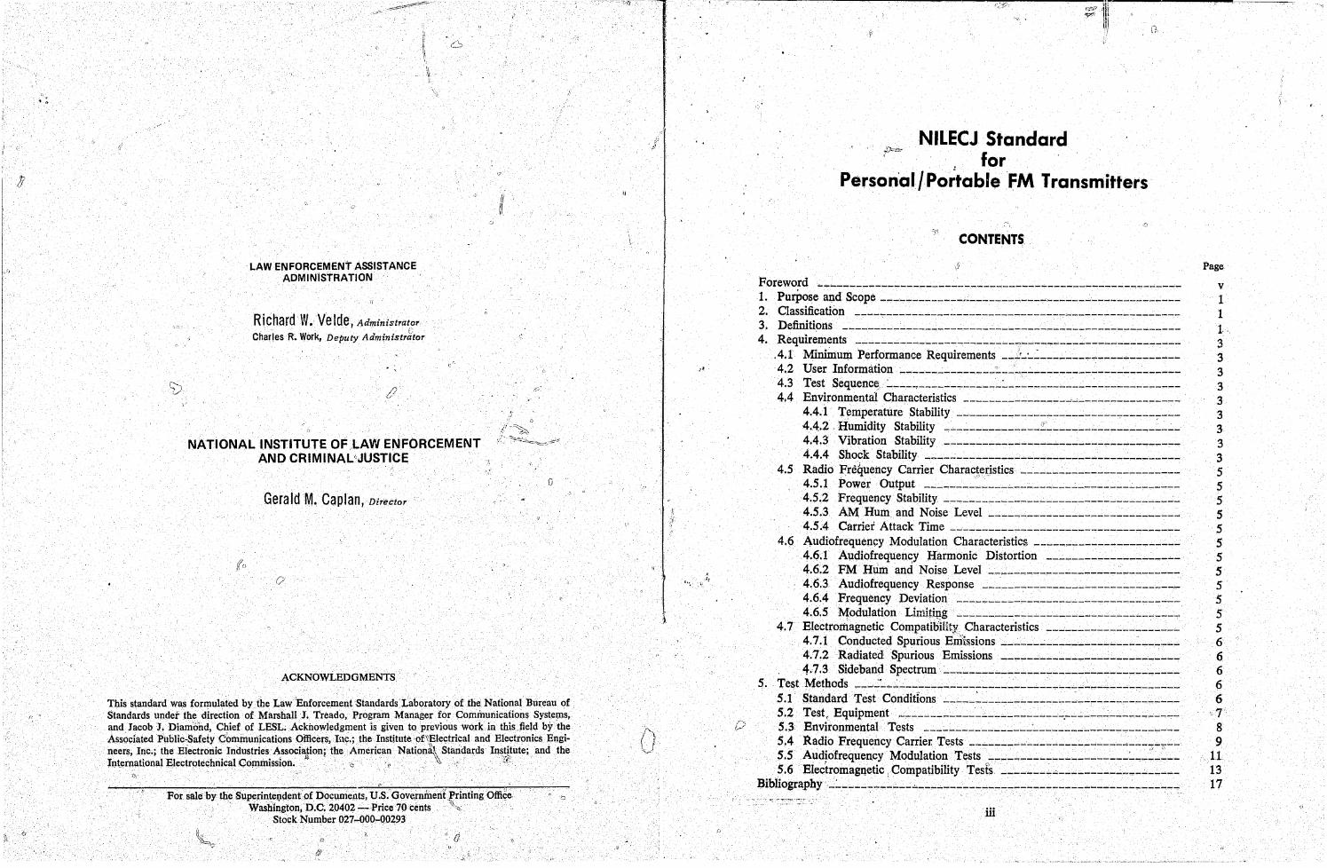
CONTENTS
Foreword ~~-------------------------------------------------------1. PurPose and. Scope _____________ .. ________________________________ _
2. Classification _________________________________ ~ ________________ _
3. Definitions ______________ ~--------------------------------------4. Requirements ---------~---------------c..:------------------------
.4.1 Minimum Performance Requirements __ j_'-~ ________ ._. ____________ _ 4.2 User Information _______________ :.. __ ~ _______________ ...: ________ _
4.3 Test Sequence: .. :.. ___ ~------.,_------:..---------------------------4.4 Environmental Characteristics ________________ ~ ________________ _
4.4.1 Temperatlire Stability _________________________ .,_---------4.4.2 . Humidity Stability _________________________________ ~ __ _ 4.4.3 Vibration Stability _________________________ .,.. _________ ,-_
4.4.4 Shock Stability ------------------"C'---------------------4.5 Radio Frequency Carrier Charact.er.istics ______ ..:. _________________ _
4.5.1 Power Output ________ ~ _____________ ------------------4.5.2 Frequency Stability _______________ ..:. ____________________ _ 4.5.3 AM Hum and Noise Level _____ --------________________ _ 4.5.4 Carrier Attack Time ___________________________________ _
4.6 Audiofrequency Modulation Characteristict; ______________________ _ 4.6.1 Audiofrequen~y Harmonic Distortion ___________________ ~_ 4.6.2 PM Hum and Noise Level ____________________ .:.. ________ _ 4.6.3 Audiofrequency Response ______________________________ _
4.6.4 Frequency Deviation ____ ------~------------------,..-----4.6.5 Modulation LimHi!,lg _________________ ------------------
4.7 Electrorriagnetic Compatibility Characteristics ____________________ _ 4.7.1 Conducted Spurious Enii&sions ~ __________ ~ _____ ~ ___ .:. _____ _
4.7 .2 Radiated Spurious Emissions ~---------------------....:-----4.7.3 Sideband Spectrum :... _______ '-___________________________ _
5. Test Methods __ ~.:... __ ..:. ___________________________________________ _ 5.1 Standard ·Test Conditions _____ ~ ______ .;.. _______ ~ ___ .;.. ___________ _
5.2 Test, Equipment . .;_-~----------'-------------.------..:------_----5.3 Environmental Tests _______________________________________ _ 5.4 Radio Frequency Carrier. Tests ________________________ ~ __ ~_-".--
5.5 Aud~ofrequency Modulation Tests _____ .,.----------------:..._._~_:--5.6 Electromagnetic: Compatibility Tests ________ -'-__________________ _
Bibliography _____________ "-_____ -------------------------------____ _
iii
Page
V
1 1 1· 3 3 3 3 3 3 3 3 3 5 5 5 5 5 5 5 5 5 5 5 5 6 6 6 6 6 7 8 9
11 13 17
I f I~
,,'
r i i
,.
. ;
-.
o
!J
o
()
i\ ,JC'I c5t]
F~REWORD
Following a Congressional mandate'" to develop new and improved techniques, ~,ystems, and equipment to strengthen law enforcement and criminal justice, the Nationatl'Institute of Law Enforcement and Criminal Justice (NILEP) has established the Law Enforcement Standards Laboratory (LESL) at the NatiorlaJ. Bureau of Standards. LESL's function is to conduct research' that will assist law enforcement and criminal justice agencies ih the selection and. procurement of quality equipment.
In response to priorities established by NILECJ', LESL. is (1) subjecting existing equipment to laboratory testing and evaluation and (2) condudtiiI~research leading to the development of several series of documents, including national voluntary equipment standards, user guidelines, state,.()f-the-art surveys and other reports.
This document, NILECJ-STD-0203.00,Personal/Port'able FM Transmitters, is a law enforcement equipment standard developed byLESL and approved and issued by NILECJ. Additional standards as well as other documents will be issued under the LESL program in the areas of protective equipment, communIcations equipment, security systems, weap-
~=oi1s, emergency equipment, investigative aids, vehicles and clothing.
This equipment standard is a technical document consisting of performance and other requirements together with a description of test met):lOds. Equipment which can meet these requirements is of superior quality and is suited to the needs of law enforcementagencies. Purchasing agents can use the test methods described in this standard to determine firsthand whether a particular equipment item meets the requirements of the standard, or they may have the testsconduct~d on their behalf by a qualified testing laporatory. Law enforcernent personnel may also reference this standard in purchase documents and require that any equipment· offered for purchase meets its requirements and that this compliance be either guaranteed by the vendor or attested to by an independent testing laboratory.
The necessarily technical nature of this NILECJ standard, and its special focus as a procurement aid, make it ·of limited use; to those who seek general guidance concerning personal/portable'FM transmitters. The NILECJ Guidelines Series is designed to fill that need. We plan to issue guidelines to this as well as other law emorcement equipment as soon as possible, within the (.!onstraints of available funding and the overall NILECJ program, I[
1.,)
The guideline documents to beissuep. are highly readable and tutorial in nature. in contrast to the standards, which are highly technical and intendeg for laboratory use by technical personnel. The guidelines will provide, in non-technical language, information .for purchasing agents and other interested persons concerning the capabilities of equipment currently available. They may then select equipment appropriate to the performance required bytli~jr agency. Recommendations for the development of particular guidelines should bel!entto us.
NILECJ stand!1rds are subjected to continuing review. Technical comments and recommended revisions are invited from. all interested parties. Suggestions should be ad-
"'Section 402(b) of the Omnibus Crime Control and Safe Streets Act of 1968, as amended.
v
__ I1111!111"""'IIII!III!!I!I!I!!!I!IIIII!I!I!IIIIII!II!!IIIII-... -I!!11111----------~-------lff!!--, -....,.------------~~--,"';:-, -===~~---:-:_~----~--~--'-.--.--.. --.-'--'-'----'-'-';. w,,,",,,_ .... ',_\\,,,,,, -_M·'''''''''''·'· __ '''··'''-''''"''''''·'' " f '
r:~ " "
[ I'
I, '
. ,
~, ",'
dressed to the Program Manager for StandardS, National Institute 'of Law Enforcement and Criminal Justice Law Enforcement Assistance Administration, U.s. Pepartment of , , ~
Justice, Washington, D.C. 20531.
Lester D. Shubin Manager, Standards Prograin National Institute of Law
Enforcement and Criminal Justice
Q
vi
!'
o
NllECJ STANDAR[' FOR
NILECJ-STD-0203.00
PERSONAL I PORTABLE FM TR'ANSMITTERS
1. PURPOSE AND SCOPE
The purpose of this document is to establish performance requirements and methods of test for frequency modulated personal/portable transmitters used py law enforcement agencies. This standard app1i'~s to transmitters which either do not have special subsystems such as selecti~esigha1ing or voice privacy, orin which such subsystems are bypassed or disabled dud~g testing for compliance with this standard.
2. CLASSIFICATION
, For the purposes of this standard, personal/portable FM transmitters are classified by their operating frequencies.
2; 1 Type I Transmitters which operate in the 400-512 MHz band.
2.2 Type II~, Tran~mitters which operate in the 150-174 MHz ban~.
2.3 Type III Transmitters which operate in the 25-50 MHz band.
3. DEFINITIONS
. The principal terms used in this document are defined in this section. Additional definitions relating to law enforcement communications are given in LESP-RPT-0203.00, Technical Terms and Definitions Used with Law Enforcement Communications Equipmimt (Radio Antennas, TransmHters, and Receivers) [1].
3.1' AM Hum and Noise A measure of the amplitude modulation present on an unmodulated carrier.
'~ 3.2 Audiofrequency Response The degree of precision with which the frequency deviation of a transmitter responds
to a designated audiofrequency signal level.
3.3 Authorized Bandwidth The maximum, width of the band of frequencies specified by the FederalCommuni
cations Commission to be occupied by an emission.
3.4 Carrier Attq~k Time The time required, after the carrier control ~witch is activated, for the transmitter to
produce 50 percent of the rated carrier power output. . . '1'
1
i '~
\ , "
a
~~- ~ -~ -, ,------~----~ --.,.,----""""!!'"",----------,;-----,---------
3.5\ Carrie .. Power 0l~tput 'I
.for a transmitter, th~, carrier radio frequency power available at the antenna terminal "When no modulatinl~ signal is present.
'\,
3.6 C~nducted Spurious Emission (Any~,p?rious signal, cO.nduct:d over a tangible transmission path,. For personal/po~t':'
able'>-if.rtlSIiIItters, any SpUrIOUS sIgnal conducted to the antenna termmals and thusavallable for radiation by the antenna.
\\ .
3.7 FM HJm and Noise A measure''''?f the frequency modulation pJ;esent on an unmodulated carrier.
3.8 Frequency',Peviation (~ In frequency m'bdulation, the peak difference between the instantaneous frequency of
\ ,<.,
the modulated wave :ai~p the carrier fr~'1u5ncy.
3.9 Frec;uency Sta\i~ity The f;lbHity of the trai'\smitter to maintain art assigned carriei' frequency.
'\
3.10 Harmonic Di5torti~l~ Nonlinear distoltion of a~'lystem or transducer characterized ,by the appearance in
the output of harmonics; in addition to the fundamental component, when the input wave is sinusoidal. \ . '.
'~i\:.-,
3.11 Modulation Limit~ng That action, performed within the modulator, which' intentionally restricts the signal
to the required spectral and power limifa~ions. ~\
3.12 Occupied Bandwidth (By an. Emission) The width of the frequency band c(jnt~ining those frequencies upon which a total of
99 percent of the radiated power appears, ex\tended to include any discrete frequency upon which the power is atJeast 0.25 percent of toi~l radiated power.
3.13 Radiated Spurious Emission Any spurious signal radiated by the tfj\qsmitter components, rather than by the an-
tenna. ;~.:;'
3.14 iSampler A series device which couples energy over a b.r!(';ld frequency range from atransmis
sion line into a third port. The attenuated output 'signal from the third porthas:the same waveform as the original signal.
3.15 Sideband Spectrum t)
The emissions generated by a modulated transmitter which are within 250 percent of tlle authorized bandwidth.
3.16 SINAD Ratio A measure of the audio output of a receiver, expressed inciecibels, equal to th~, ra~o
of (1) signal plus noise plus distortion to (2) noise plus distortion; from SIgnal Noise And Distortion Ratio. ~ ~
3.17 Spurious Emission Any part of the flldiofrequency output that is not a component of the theoretical out~
put or exceeds the speeifiedbandwidth.
2
3.18 Standby Mode . The conditio~ ~ a ,transmitting an~f receiving system when the system is ener-
gIzed but not r~_celVlng or transmitting. J ' 4. REQUIREMENTS
4.1 Minimum Perfo~mance Re'k~i~erri'ents The requirement for each transmitter characteristic shall be the value listed in table
1 (page 4). These performance reqUirements are in accordance with those given in the Rules and Regulations ,published by{,the Federal Communications Commission (FCC)., In addition to the requirements }isted, all of the licensing and operating requirements of the FCC Rules and Regulations shall apply.
4.2 User Information
A nominal value for carrier output power, carrier frequency and each transmitter charaCteristic shall be included in the information supplied to the user by the manufactu~er or distrib?t~r. The. manufacturer shall specify the required power supply voltage, indIcate the audIO mput SIgnal necessary for rated ,system deviation and provide sufficient audio input impedance information to enable test personnel to design an impedance matching network for use between the audio generator and transmitter audio input circJ.tits.
4.3 Test Sequence
Each transmitter shall be subjected to the environmental tests before being tested for conformance with paragraph 4.5,4.6 and 4.7.
4.4 Environmental Characteristics
The ability of the transmitter to operate in environmental extremes shall be determined using the test methods described in paragraph 5.3.
4.4.1 Temperature Stability
When the transmitter is operated at temperatures of - 30° C (-22° F) and~O() C (140 0 F), its power output shall be within JItemO, table 1) of the nominal value, its FM bum and ~oi~e level shall be attenu~ted a minimum of (Item P), the carrier frequency shall be withm (Item Q) of the assIgned value and the audiofrequency harmonic distortion shall be a maximum of (Item R).
4.4.2 Humidity Stability' ~' ..
'_.~ "After/the trans~itter has been maintained at 50° C (122 0 F) and 90 percent r~la- . . ~- tive humidity for eight hours or more, its power output shall be within (Item S) of the
nominal value, its FM hum and noise level shall be attenuated a minimum of (Iteni~'T) and the carrier frequency shall be within (Item U) of the assigned value.
4.4.3 Vibration. Stability
No fixed part of the transmitter shall come loose, nor movable part be shifted in position or adjustment, as a result of this test. During the test, the FM hum and noise level shall peattenuated a minim11tp of (Item V) and the carrier frequency shall be within (Item W) of the assigned vahie.
4.4.4 Shock Stability
Tlie transmitter shall suffer'no more than superficial damage as a result of this test.:
3
II
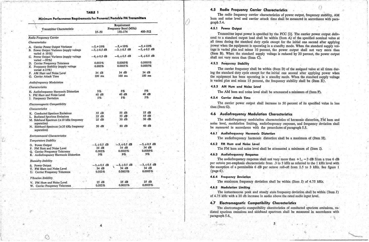
TABLE 1
Minimum Performance Requirements forPersoncd/Po'!l'lble FM Tranlmitter. ;
.' Requirement \\
Transmitter Characteristic Frequency Band (MHz) 25-50 150-174 40Q-.·SIZ
Radio Frequency Carrier
Characteristics
A. Carrier Power Output Variance .;...5,+10% ~5,+10% -S,+10% B. Power Output Variance (supply voltage' -3,+0.5 dB -3.+0.5 dB -3,+0.5 dB
varied:!: 100/'0) -6,+0.5 dB '. C. Power Output Variance (supply voltage -6,+0.5 dB -6,+0.5 dB
i varied -2{}%) I
Carrier Frequency Tolerance 0.002% 0.0005% 0.0005% L D. E. Frequency Stability (supply voltage 0.002% 0.0005% 0.0005%
varied :!:15%) 34 dB F. AM Hum and Noise Level 34 dB 34 dB
O. Carrier" Attack Time 100 ms 100 rns 100 rns
Audlo!reqllellcy Modlliatioll
Characteristics
H. Audiofrequency Harmonic Distortion 5% S% 5%
I. FM Hum and Noise Level 40 dB 40 dB 40 dB
" J. Frequency Deviation 5% 5% 5%
Eiectroillagnetic Compatibility
Characteristics
K. Conducted Spurious Emissions 55 dB 5S dB 55 dB L,. Radiated RPurious Emissions . 55 dB 55 .d~· 55 dB M. Sideband iSpectrum (:!: 10 kHz frequency 25 dB 30 dB 30 dB
separation) 60 dB 60 dB N. Sideband Spectrum (:!:20 kHz frequency SO dB
separation)
EllVirollmelltal Characteristics
Temperature Stability
O.Power Output -3,+0.5 dB ::....3.+0.5 dB -3,+0.5 dB
P. JIM Hum and Noise Level 34 dB 34 dB 34 dB
Q. Carrier Frequency Tolerance 0.002% 0.0005% 0.0005% R. Audiofrequency Harmonic Distortion 9% 9% 9%
Hu(nidity Stability
·s. Power Output -3,+0.5 dB > -3,+0.5 dB -3,+0.5 dB
T. FM Hum and Noise Level 34 dB .. 34 dB 34 dB
U. Carrier Frequency Tolerance 0.002% 0.0005% . 0.0005%
Vibratioll Stability
V. FM Hum and Noise Level 25 dB 25 dB 25 dB
W. Carrier Frequency Tolerance. 0.002% 0.0005% 0.0005%
(J 4
I i
I ' ! f
r
l
I \~ j
\
4.5 Radio Frequency Carrier Characteristics" ,;) The radio frequency carrier characteristics of power output, frequency stability, AM
hum and noise level and carrier attack time shall be measured in accordance with paragraph 5.4.
4.5.1 Power Output
Transmitter input power is specifieft by the FCC [2]. The carrier power output delivered to a standard output load shall be within (Item A) of the specified nominal value at all times during the standard duty cycle except for the initial one second after applying power when the ,~quipmcIlt is operating in a s tandb~~ mode. When the standard supply voltage'is varied plus .and ininus 10 percent, the power output shall not vary more than (Item B). WI;ten the standard supply voltage is reduced by 20 percent, the power output shall not vary more than (Item C).
4.5.2 Fre'quency Stability
The carrier frequency shall be within (Item D) of the assigned value at all times during the standard duty cycle except for the initial one second after applying power when the equipmttpt has been operating in a standby moqe. When the standard supply voltage is varied plus and minus IS percent, the frequency stability shall be (Item B).
4.5.3 AM Hum and Noise Level
The AM hum and noise level shall be attenuated a minimum of (Item F).
4.5.4 Carrier Attack Time
The carrier power output shall increase to 50 percent of its specified value in less than (Item G).
4.6 Audiofrequency Modulation Characteristics
The audiofrequency modulation characteristics of harmonic distortidn, FM hum and noise level, modulation limiting, audiofrequency response, and frequency deviation shall be measured in accordance with the procedures of paragraph 5.5.
4.6.1 Audiofrequency Harmon.ic Distortion
The audiofrequency harr.nonic distortion shall be a maximum of (Item H).
4,6.2 FM Hum and Noise Level
The FM hum and noise level shall be attenuated a minimum of (Item I).
4;6.3 Audiofrequency Response .
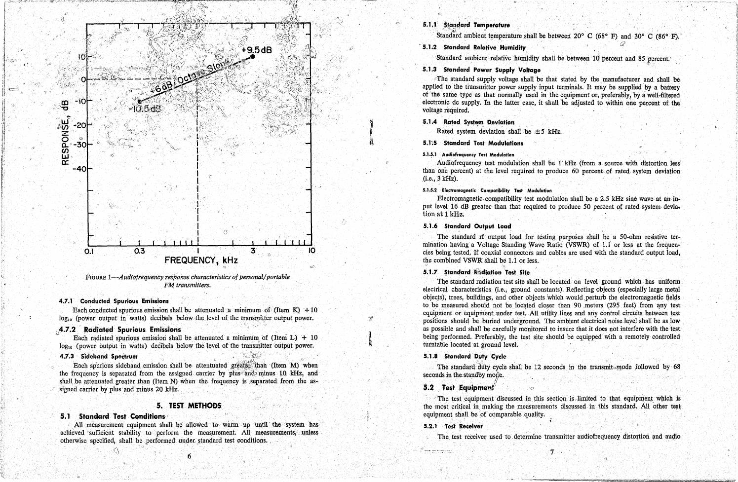
The audiofrequency response shall not vary more than + 1'1 -1,;' dB fi\OIn ~ true 6 dB per octave pre-emphasis characteristic from .3 to 3 kHz as referred to the 1 kHz level with 'the exceptipn of a permissible 6 dB per octave roll-off, from 2.5 to 3 kHz. See figure 1 (page 6):
4.6.4 Frequency Deviatio.n
The maximum frequency deviation shall 'be within (Item J) of 4.75 kHz~
4,.6.'$ Modulation Limiting " ~
The instantaneous peak and steady state frequency deviation shall be within (Item J) of 4.75 kHz with a 20 db increase in audio above the rated audio input level.
Electromagnetic Compatibility Characteristics , The electromagnetic compatibility charateristics of conducted spurious emissions, ra
diated spurious emissions and sideband spectrum shall. be measured in accord~nce with 'paragraph 5.6."",
\\
5
, ' i,
, .
0.1 0.3 I FREQUENCY, kHz
"
'V
FIGURE I-A udiofrequency respOnse characteristics of personal/portable FM transmitters.
4.7.1 Conducted Spurious Emissions Each conducted spurious emission shall be attenuated a mllllmum of (Item K) + 10
loglo (power output in watts) decibels below the level of the traosmitJeroutput power.
r 4.7.2 ' Radiated Spurious EmiSSions , ,.,' , o Each radiatedspurlous emissiori shall be attenuated a minimum:; 'Of (Item L) + 10
Ioglo (power output in watts) decibels below the level of the transmitter output power.
4.1.3 S'ideband Spectrum " ' '!~~;;.' ' '"
':0 Each spurious ,sidebancl.emission ,shall be attent~ated, ,Si:~1t~~:~'\~hah (Item M)' when the frequency is separated from the assigned carrier byplus;;~,Q~m.inus 10 kHz, and shall, be attenuated greater than (Item N) When the. frequency is' ,separated from .the assigned carrier by plus and minus 40 kfIz., ,
5. TEST METHODS 5.1 Standard Test Conditions
'All ,meaSurement equipment shall be allowed to warm up until ' the system has ' " achieved sufficient &tability to perform the meas,urement. All measurements, unless otherwise specified, shall be performedunder.~tandard test conditions. ,
6
"
, .. ~',
"', '
5. L 1 ~StflP~cird. Te"!perature : ; -'b.~. \;
Standard ambient t~mperature shall be between 200 C (68 0 F) and 300 C (86 0 F).'
. 5.1.2 Standard Relative, Humidity,
Standard ambient relative humidity shalibe between 10 percent and 85percent.t' . -.~
5.1.3 Standard Power Supply Voltage ::The standard supply voltage shall be that stated by the manufacturer and shall be
applied to the transmitter power supply input terminals. It may be supplied by a battery of the same type as that normally used in the equipment or, preferably, by a well-filtered electronic dc supply. In the latter case, it shall be adjusted to within oile percent of the voltage required.
5.1.4 Rated System D.eviation t " l'
Rated system deviation shall be ± 5 kHz.
5.1-;5 Standard Test Modulations
5.1.~.1 Audiofrequency lest Modulation
Audiofrequency test modulation shall be l' kHz (from a source withdistortlon less' than one percent) at the level required to produce 60 percent of rated, system deviation (i.e., 3 kHz).
5.1.5.2 Electromagnlltic CompatibUity Te$t Modulation
Electromagnetic. compatibility test mqdulation shall be a 2.5 kHz sine wave' at an iQ.put level 16 dB greater than that required to produce 50 percent of rated system devia" tion at 1 kHz.
5.1.6 Standard Output L~ad
The standard rf output load for testing purposes ~hall be a 50-ohm r:esistive termination having a Voltage Standing. Wave Ratio (VSWR) of 1.1 or less at the frequencies being tested. If coaxial connectors and cables are used with the standard output load, the combined VSWR shall be 1.1 or less.
'\
5.1.7 ~tandardr&ediation Test Site The sta'ndard radiation test site shall be located on level grollnd which has uniform
electrical characteristics (Le., ground constants). Reflecting objects (especially large m~tal objec.ts), trees, buildings, and other objects which would,perturb the electromagnetic ijel~s to be measured. should not be .located closer than 90.meters (295 feet) from~ny test equipment or equipment under test: All utUity li~esand any control circuits between test positions should be buried Uliderground. The ambient electrical noise leyel shall be as low as possible .and shall be carefully monitored to insure that it does not interfere with the test being performed. Preferably, the test site should be equipped with a remotely controlled turntable located at ground level.
5.1.IISfandard Duty Cycle 0' .... 1;
The standa.rcl dtitycyc1e shall be 12 seconds in the transmit::e,.11Jode followed by .. 68 seconds in tbe. standby moCJ;e. . ., II, 5.2 TestEq~ipmt!~~! 0
The test equipment discussed. in: this section is limited to that equipment, whicl1 is the most critical in making the measl1remepts discussed in this standarcl. All other te~~ equipment shall be of cqmparable quality. .
, '~ ;
5.2.1 . Test Receiver
The. test receiver used to. determine transmitter audiofrequency distortion and audio
7 . (J

.. .,/
, re,r;::$IRPsecharacteristics shall include. a' .standard audi() output load specified by the manuf~~t\lrer (paragraph 5.2,1.6), and shall have the characteristics specified in the foll()woo:
(::\I~H)aragr~phs. ,) /' .
';Jif4; j.1 . Audio Respons9
,', . The ~ audio respon:b~ characteristics shall not vary more than one decibel from a 750 'microsecond de~emphasis characteristic when the system deviation is held constant and' . . the modulation is varied between ,05 and 3 kHz.
~~2.1.2' Harmonic Distortion
The audiofrequency distortion shall' be less than one percent at standard modulation. Tbeharmonic{ distortipn at 1 kHz (~or'larger than rated system deviation) shall be less tMn::; three percent. The harmonic distortion shall be measured. when the . test receiver iii tuned to a nominal 1 millivolt rf source which is modulated by a sine wave at a level which produces a system deviation 50 percent greater than rated system deviation (1.e., 7,:; kHz). "
5.2.1,3 Hum and Noise Ratio I
fl
The unsquelched hum and noise ratio shall be at least 55 dB when measured, with a 1 millivblt input signal.
~.2, i.4 Adjacent Channel Interference
The test receiver shall differentiate by 85 dB or more between a desired modulated , sj~nal and a modulated adjacent channel signal' 30 kHz on either side, when t~e adjacent lfhannel interference degrades the desired signaLirom 12 dB SINAD to 6- dB SINAD.
~.2.1;5 'Solectivity , The test receiver shall have a bandwidth of 24 to 30 kHz at the 80 decibel points. . ' , ~: . ,
5.~.1,6 Standard Audio Output Load '. . . ' 1 \ •
The standard audio output load shall consist of a resistor whose resistance is equal to the load impedance intq which tne recelver normally operates.
..,~
$.2.2 Deviation Monitor
The deviation monitor shall be capable of measuring th~.peak deviation of a ID.bd~da.ting waveform with an· uncenainty no greater than five pe.ic:ent of the deviation being plj:mitored. . . ,
~.2.3 Standard Audio' Input Load
The standard audio inputload shall consist of a low-noise resistor whose resistanc~ is equal to the specified input impedance of the transmitter.
, . ':'
5,2.11 Band ,Rejection Filter
The band rejection filter shall have a minimum insertion loss qucncies within ±0.01 per~ent of the carrier frequency.
$.3 Environme~tal Tests
of 40 dB for'~ll fre'-
I
Th¢environmental 'te~ts shall be performed using standard' supply volt~ge and the measurement techniques described in paragraphs 5.4, 5.5 and,5.6, ascrequirea.
$13.1 Temperature Test '. '. (~I .~' -":r',~;;:;:" "
The' transmitter shall be placed in an envb:onmental cb'luil,ger whose "1:bhperatllJtl is J11@intilined at - 30 ±: 2° C (-22 ± 3.6 OF). The outer cases shall be in pla.ce and air tur:~
. r~n,ts from heating or cooling elements shall not be allowed to blow directly on the trans,111itter. T~e transmitter shall not require adjustment of internal controls to meet th'&lmini.,
o
c)
"
, \', ti •.
mum requirements. Further, the llnenergized transmitter shall be anow'ed to reach tempera-' ture, equiHbriu~ with its surroundings after each temperature ch~nge. The transmitter shall be kept at the desired temperature for 30 minutes, before eneq~izatioh. While, still in the chamber, the transmitter shall be placed in the standby mode for two minutes, operated~ at the staridard 'duty cycle. for 15 minutes. and then tested for ~he designated performance requirements. This test shall be repeated at a temperature of 60±2° C (140±3.6° F).
,>
5.3.2 Humidity Test ',,i
The unenergized transmitt~r shall be kept for eight "hours in an environmental cham..; ber at a temperature of 50° C (122°F) or more and a relative humidity of at least 90 percent. All covers and shields shall be in place and air currents froD;l heating elements shall not be allowed to blow directly on the transmitter. While stili in the chamber, the trans,. mitter shall be placed in the standby mode for two minutes; operated at the standard duty cycle for 15 minutes ang then tested for th~ designated performance requirements. The transmitter shall not require adjustments of any controls during this test. , 5.3.3 Vjbration Test i A two-part test shall be applied for a total of 30 minutes in each of three directions, namely the directions parallel to both axes of the base and perpendicular. to the plane of the base ..
The unit shall complete three' five-minute cycles of simple harmonic motion havini an am.plitude of 0.38 mm (0.015) inch) [total excursion of 0.76 mm(O.03 inch)] applied initially .at a frequency of 10 Hz and increased at a uniform rate to 30 Hz in two and one-half minutes, then decreased at a uniform rate to 10 Hz in two and one-half minutes.'
The unit sha:!l next complete three five-minute cycles of simple harmonic motion having an amplitude of 0.19 mm (0.0075) inch) [total excursion 0.38 mm (0.015 inch)] applieq initially at a frequency of 30 Hz and increasing at a uniform rate to 60 Hz in two and one-half minutes, then decreased at a uniform rate to 30 Hz in two and one,. half miIiute&;-"~ ,
; \ . '"" 5.3.4 Shock Test
The transmitter shall be dropped once on .each of four or more sides not having an antenna connection, from a height of one m~ter (3.28' feet) onto a smooth concrete floor. Guides shall be.used to insure contact withthe floor by the correct equipment surface.
5.4 Radio Frequency Carr~er Tests
5.4.1 Power Qutput Test ".
The transmitte~shall be operated Without mod'\llation. The power output shaH be measured as!lhown in figure.2 (page 10) using the standard supply voltage and a power meter accurate to five percent. The standard supply voltage shall then be changed plus: 10 percent, allowed to stabilize at least 5 seconds, and the power output recorded.Repeat the above using minus 10 percent and minus 20 percent changes in standard supply' voltage.
5,4.2 Frequency Stability Test The transmitter shall be operated without modulation. The frequency shall be meas
ured as. shown. in figure 3 (page 10) using standard supply voltage. Change the standard supply voitage plus 1.5 percent, allow.it to stabilize for 5 seconds, and record the change in frequency. RepClat this for a change in standard supply voltage of minus 15 percent.
5.4.3 AM Hum and Noise. Level Test .
Connecttpe equipment as shown in figure 4 tpage 10). In addition, connect the ,standard audio input loac:i to the transmitter audio iIlpUt. The linear peak-carrieo:esponsive AM detector is used to detect the-sample output of the transmitter. Adjust the transmitter
". 9
. ,
+
1/.
VARIABLE TRANSMITTER pOWEiR STANDARD
PO~ER UNDER METER OUTPUT
SUP LY TEST lj LOAD
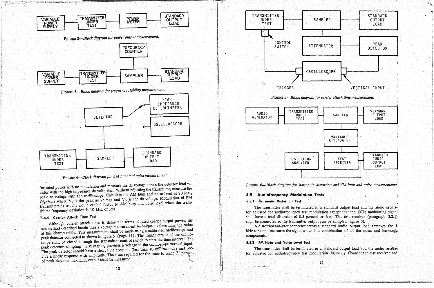
Ft9u3E ~B1Qc:k 4iCl#ram for power ozttput measurement . .J
FREQUENCY , '.'-:,.
COUNTER
c
VARIABLE TRANSMITTER . STANDARD
POWER UNDER SAMPLER OUTPUT
SUPPLY TEST " LOAD ~
FIGURE 3-Block diagram for frequency stability measurement.
HIGH
V IMPEDANCE
DC VQL TMETER
; DETECTOR ,
0-OSCILLOSCOPE
'"
TRANSMITTER STANDARD
UNDER I----" SA.MPLER ~ OUTPUT TtST
. LOAD
FIGURE 4-Block diagram for AM hum af/d noise measurement.
for xated powe,r with no modulation and measure the dc voltage across the detector load resistor wHh the high imped~nce dc voltmeter. Without adjusting the transmitter, measure the petak ac voltage with the oscilloscope. Calculate the AM hum and noise level as 20 Ipglo (Vp/Vd
O) where V» is the peak ac voltage and Vdc.iS the dc voltage. Modulation of PM
tr;ansmjtters is usua1ly not a critical factor to AM hum and noise level when the trans-
~hitter frequency deviation is 10 kHz or less. ,{i
}5.4.4 Carrier Attack Time. Test Although carrier attack time is. defined in terms of rated carrier output power,the
test method descdbed herein UseS a voltage measurement technique JO determine the value of this characteristic. This measurement shall be made using a· calibrated oscilloscope and peak detector connected as shown in figure 5 (page 11). The trigger circllit of the oscillo~ scope shall be closed through the trapsmitter control switch to start the time interval. The peak detector, sampling the rf carrier, provIdes a voltage to the osciUos~ope vertical input. The peak detector shOuld have a snort time constant (less than 10 mill~econds) a~dprovidea linear response with amplitude. The time required for the trace to reach 71perq,ent of peak detector maximum output shall be measured, . t " . .~-~
10
TRANSMJTTER UNDER
TEST ':
CONTROL SWITCH
$AMPLER
ATTENUATOR
OSCILLOSCOPE o
STANDAR'O OUTPUT
LOAD
TRIGGER VE~J I CAL INPUT
FIGURE 5-Btock diagram for carrier attack time measurement.
AUDIO TRANSMITTER STANDARD GENERATOR ........... UNDER t--" SAMPLER I-- OUTPUT
TEST LOAD
I
VARIABLE ATTENUATOR
I . STANDARD
DISTORTION TEST AUDIO ANALYZER RECEIVER .. OUTPUT
LOAD
1
~
,
,
,
"
FIGURE 6-Block diagdlln for harmonic distortion and PM hum and noise measurements.:
5.5 Audiofrequency Modulation. Tests 5.5~ 1 Harmonic Distortion Test
. T.he transmitter .shall be ~erminated in . a standard output load and the audio osciUa: tor adjusted for audlofrequency test modulation except that the lkH~ mbdulat'n . i shall have a total distortion of ~,5 percent or less. The test receiver (paragra
1
hg
~~~~: shall be.~onn~cted so the transmttter outputqan he sampled (figure 6). p )
A dlstor~lOn analyzer connector across a stan,dard audio output load removes the 1 kHz tone and measures the signal which is a combination of all the nois ' .. components. . e and harmonj9'
5.5.2 . FM Hum and Noise level Test
The transmitter shall be terminated in a standard output load and the ud' 'II' . i. tor adjusted f' d' f . ' . a to aSCI a .. .. ' or au 10 requency test modulati~;m (figure 6), Connect the test receiver ana
11
('
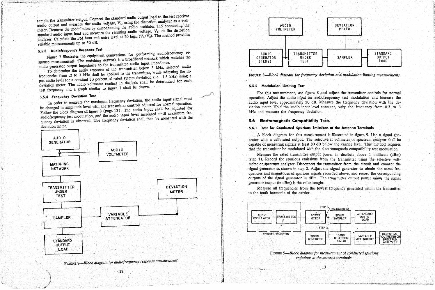
, ' , '" nect the standard-audio output 10~? to the, test receiver samP.,Ie the transmItter outpu~, con
d, l't ' 'V' "sl'ng the disfo. rtion an, alyzer as a. volt-
• d nre We" au 10 vo age, 1, u , , , h aUOIOQutputan me~s., , b d' 'ting the audio oscillator and connecting t e metet. Remove the modulation ~ . Isconnec ultiriaudio v01tage V
2,at the distortion
slandard audio input load and measd·ure ~b\res 1 as ~O log (Vt/V
2). The method provides
anMyzcr. Calculate the FJ:.4 hum an ,nOIse eve ,ill .'
reliable measurements up to 50 dB. '
5 5 3 Audlofrequency ~esponseTest . • , ". " . . f r performing audiofrequency re-
Figure 7 illustrates the equip~ertt conn~c~~o~sbrooadband network which matches the sponse measurements, ~he matchmg networ mitter audio input impedance. audio generator output lDlp;dance to the f tr~ns transmitter below 3 ldlz, selected audio
To .determine the audIO response 0 tH
: d to the transmitter, while adjusting th~ infrequencies .from .3 to 3 kHz shall be app stem deviation (i.e., 1.5 kHz) uSIQg a put audio leve1 for a constant 30 percent °df. rate,d s~ 'b~l"'shall be determined for each deviation meter. The audio voltmeter rea 109 10 eCl ~."
h "il t figure 1 shall be drawn. test frequency and a grap Slm aro
5.5.4 .Frequency Deviation 'test ., '1 must In order to measure the maximum frequency deviation, t~e audlo toput _ sl~:ration
be changed in amp.Htude level with the transmi~te~~~n!~o~~oa~~~~~d !Oa;t~::~j!ted fo; Follow tbe block dIagram Of. figure 8 ~age 1-3
) i ut level increased until maximum fre~ audiofrequency test modulatton, and t e au 10 :P, r shall then be measured with the quency deviation is observed. The frequ.ency eVlB Ion
deviation meter.
AUDIO I GENERATOR '.
AUDIO 1 T VOLTMETER
MATCHING, NETWORK
I TRANSM ITTER DEVlATlON
UND~R METER TEST
I "
;
, VARIABLE " SAMPLER ATTENUATOR
c: <'"J
r " ,-
I . STANDARD
OUTPUT , "
LOAD " . . f.'
FIOU,RE, 7-Block diagram foraudiofrequency response measUrement.
"
) 12
. ':t-. l
, I
l)
I " AUDIO DEVIATION
VOLTME.TER METER
" \.1 '
,)
AUDIO TRANSMITTER STANDARD GENERATOR I-" UNDER I-- SAMPLER !- OUTPUT
(1kHz) }.' TEST LOAD 'Ii'
FIOURE 8-Blot;:k diagram for frequency deviation aria modulation . limiting measurements.
5.5.5 Modulation' LimitillB Test
For this measurement, use figure 8 and adjust the transmitter controls for normal operation. Adjust the audio input lor audiofrequency test modulation and increase the audio input level approximately 20 dB. Measure the frequency deviation with 'the deviation meter. Holel the audio input level constant, val:Y, the frequency from 0.3 to 3 kHz and mea~lUre the frequency deviation ..
5.6 Electromagnetic Compatibility Tests
5,6.1 Test for, Conducted Spurious Emissions at the Antenna Terminals . A block diagram for this measurement is illustrated in figure 9, Use a signal gen
erator with a calibrated output. The selective rf voltmeter or spectrum ~haly'zer shall be capable of measuring signals.at least 80 dB below the carrier level. This7 nietliog requires that the transmitter- be modulated wit~ Jhe eleotromagnetic compatibility test modulation.
Measure the r:ated transmitter output power in decibels above 1 milliwatt (dBm) (step 1). Recorp' the spurious emissions from the transmitter using the selective voltmeter or spectrum analyzer. 'Disconnect the transmitter from the circuit and connect the signal generator as shown in step 2. Adjust the signal generator to obtain the same frequencies and magnitudes of spurious signals recorded above, and record the corresp0rlding outputs of the signal generator in. dBm. The transmitter olltpUt power minus the signal generator output (in dBm) is the value sought. /) .
Measure all frequencies from the lowest frequency g~nerated within the transmitter to the tenth harmonic of the carrier. ,---,
, AUDIO + OSCILLATOR I- TRA~SMITTER I L ~~~~
,SHII:':LDED ENCLOSURE
STEP (
POWER 1'1" METER
I I
STEP 21 I I
SIGNAL " GENERATOR J
(20dB MINIMUM)
SIGNAL -STANDARD r- OUTPUT SAMPLER LOAf)
I ,. BAND VARIABLE
REJECTION I- ATTENUATOR I-FILTER
FIGURE f)-Block diagram for measurement of conducted spurious emissions atthe antefma terminals.
13
SELECTIVE WLTMETEROR
SPECTRUM ANALYZER
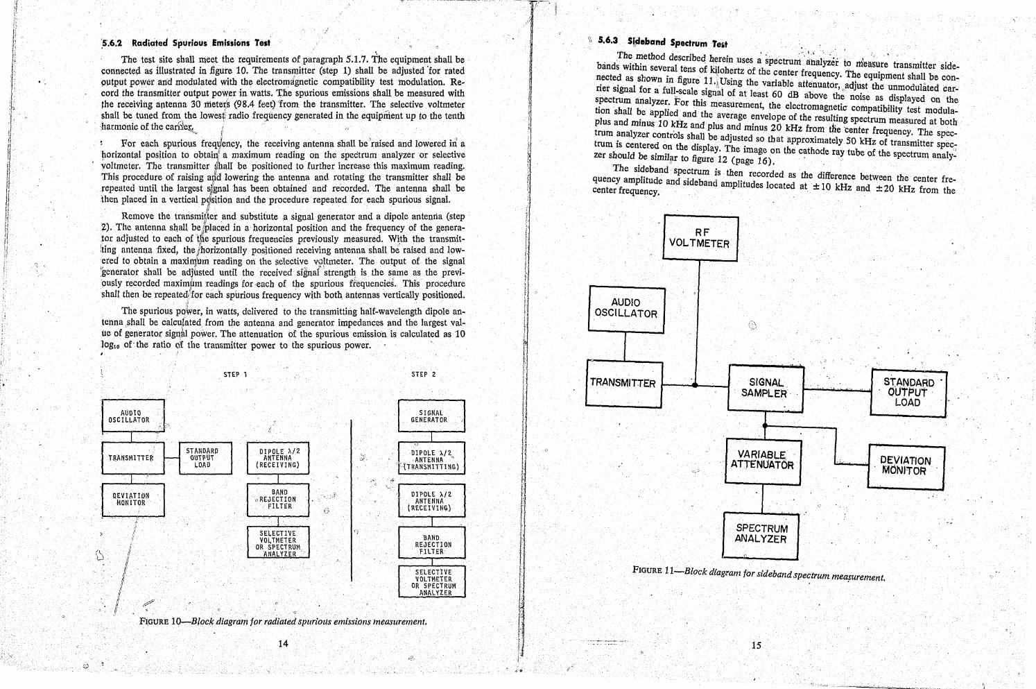
:5.6.2 Radiated Spurious Emissions Test
Tbetest site shall meetthe requirements of paragraph 5.1.7. The equipment shall be corin~cteo. as illustrated inngute 10. The transmitter (step 1) shall be adjusted 'for rated putput poweraI1d modulated with the electromignetic compatibility test modulation. Re· cord the transmitter output power in watts. 1;'he spurious emissions shall be measured with the receiving ap.tenpa 30ri:ieter,~ (98.4 feetrfrom the transmitter. The selective voltmeter shall be tuned from the lowesf radio frequency generated in the equipment up to the tenth harmonic of the cari~e~ I.. ;,
.~ I,
~For each spurious freqlllency, the receiving antenna shall beiraised and lowered in a '~orizontat position to obtainll a maximum reading on the spectrum analyzer or selective yol.tmeter. The trans~itter {hall, be. positioned to further incr.ease this maxi~um reading. ThIs procedure of raIsmg aild lowermg the antenna and rotatmg the transmItter shall be repeated until the largest s¥gnal has been obtained and recorded. The antenna :;hall be then placed in a vertical V1sition and the procedure repeated for each spurious signal.
Remove the trarismiAer and substitute ,a signal generator and a dipole antenna (step ~). The antenna sllaU bel~laced in a horizontal position and the frequency of the genera· tor adjuSted to each of t~e spurious frequencies previously measured. W~tb the transmitlting antenna fixed, th,e Ihorizontally posJtioned r,eceiV,i,ng an,terina shall be raised and, lowered to obtain a maxi~um reading on the :;elective voltmeter. The output of the signal ;gerierator shall be adjl~sted tmtil the received signarstrengt~ is the same as the previously recorded maxi~m readings fOJ"each of the spurious frequencie~. This procedure shall then be repeated/for each spurious frequency with bQt~ antennas vertically positioned.
The spurious po~er, in watts,delivered to the transmitting half·wavelength dipole antenna ,~hall be calcutated from the antenna and generator impedances and the largest valUe of generatoJ;'sign,nl power. The attenuation of the spurious emission is calculated as 10 )Og10 of" the ratio qf the transmitter power to the spurious power.
I
STEP 1 STEP 2
f AUDIO
OSCILl..ilTOR J :i_ ~:r.' >-
SIGNAL GENERATOR I
I I STANDARD
TRANSMITTER ~ OUTPUT LOAD
"', OIPO).EA/2 . ANTENNA Ie
,tTRANSMITTl NG)
DIPOLE A/2 ANTENNA
(RECEIVING)
I
''''~T~ MONITOR'
I BAND
oRE,JECTlON FILTH
I.
DIPOLE A/2 ANTENNA
t RECEIVING)
" I ,. SELECTIVE VO~ TMETER
OR SPECTRUM ANALYZER
BAND REJECTlON
FILTER' I
SELECTIVE VOLiM£TER
OR SPECTRUM ANALYZER
l
/ 1 If 1 j
ij
FI.GtJRE 10-B/ockdiagram formdiizted spurious emissiOns ineasr,trement,
14
o
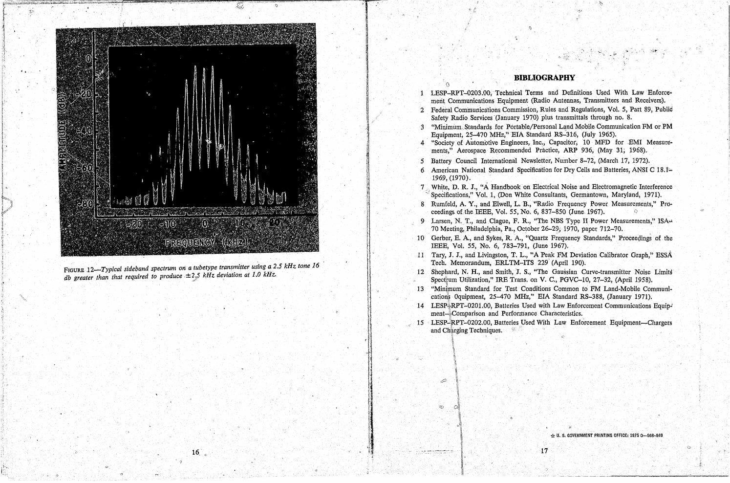
\\ 5.6.3Stdeband Spectrum Te't , Th: method describeq ~erein uses ~ spectruzrt:' ~~al' ~~'. : I,' , ,'. '; + .'
bands WIthin several tens of kil ht f 11. Y .r t? measure, transmIi.er sIdenected as sl1 '. " '.'.0 ~r z.o t e center frequency. The equipment shall be con-rier signal fo~:nf~~l_~~[e ~l'/lfSI~g t~e variable aUen\lator, "adjust the unmodulated carspectrum anal ' " e~Igna 0 at east 60 dB above the noise as displayed on the tionshall be :;;~'e;~:~h~~measurement, the electromagne.tic' compatibility test modula;. plus and minus 10 kII d e average 7nvelope of the resultmg spectrum measured at both t '. " . z an plus a,nd mmus 20 kHz from tiiecenter frequenc . The s e _ t~: :sn:~~e~ controls sh~l be adJust~d so th at approximately 50 kHz of tran~n1itter s p e~-zer should b~ ~~~~:~e dfjIsPlaY
1·2Th(e, Image on the c~thode ray tube of the spectrum an~li~
.,. 0 gure page 16).' The sideband spectrum is th "d d .
quency amplitude and sideband e~t r;co~ e ~ the dIfference between the center frecenter frequency.' amp 1 u es ocate at ± 10 kHz and ± 20 kHz from the
"
RF VOLTMETER
,
AUDIO OSCILLATOR
, . :.'
" .. ,
TRANSMITTER SIGNAL. ST.ANDARD . SAMPLEf:f·
' , .. 'OUTP>ut· LOAD
VARIABLE DEVIATION ATTENUAT6~ ....
"-
,~ MdNITO~
SPECTRUM ANALYZER
",
FIGURE 11-Block diagram for sideband spectrum measurement . ' .
15
, J
t
•··lr;;;;;-;~;,,:::c"~::,",,:~,,",J~:~:#''':~~:~"'~r":''~- -.,
" '., :~, " ;:{ .
••
FIGURE J2~Typlcal sideband spectrum on a tubetype transmitter using a 2.5 kHz tone 16 db greater than that required to produce±~S kHz deviation at 1.0 kHz.
16. '-, , \1
"F'" ... '
j
'Ii !
III ....... .
:. :'
t f
r 1 r j
r ,I f J I
! t 1 r 1 t !. r ], I: r ~ 1
t f ,.
If t (j
L f
I l.
1 I , , t ). ,. J .~ ;
,f
BIBLIOGRAPHY G
1 LESP-RPT-0203.00; Technical Terms and Definitions Used With Law Enforcement Communications Equipment (Radio Antennas, Transmitters and Receivers).
2 Federal Communications Commission, Rules and Regulations, Vol. 5, Part 89,PubUd Safety Radio Services '(January 1970) plus transmittals through no. 8.
3 "Minimum, Standards for Portable/Personal Land Mo'bile Communication FM or PM Equipment, 25-470 MHz,'jEIA Standard RS":316, (July 1965).
4 "Society of Automotive Engineers, Inc l , Capacitot;10 MFD for .EMI Measurements," Aerospace Recommended Practice, ARP 936, (May 31; 1968),
5 Battery Council International Newsletter, Number 8-72, (March 17, 1972)~ 6 American National Standard Specification for Dry Cells and Batteries, ANSI C 18. t.:..
1969, (1970). 7 White, D. R. J., l'A Handbookon Electrical Noise and Electromagnetic Interference
/ I .
. Specifications," Vol. 1, (Don White Consultants, Germantown, Maryland, 1971). 8 Rumfeld, A. Y.; and Elwell, L. B., '''Radio Frequency Power Measurements," Prd~
ceedings, of the IEEE, Vol. 55, No.6, 837-850 (June. 1967). <)
9 Larsen, N. T., and Clague, F. R., "The NBS Type II Power Measurements," IS A"" 70 Meeting; Philadelphia, Pa.~ October 26-2f.; 1970, paper 712-70. .
10 Gerber, E. A., and Sykes, R. A, "Quartz Frequency Standards,"Proceeciings of the IEEE, Vol. 55, No.6, 783-791, (June 1967).
11 Tary, J. J. j and Livingston, T. L., "A Peak FM Deviation Calibrator Graph," EssA 'rech. Memorandum, ERLTM-ITS 229' (April 190).
12 Shephard, No H., artd Smith,'J. S., "The Gaussian Curve-transmitter Noise Limits' Spec~tum Utilization/' IRE Trans. on V. C., PGVC-I0, 27-32, (April 1958). "Mini\num Startdard for Test Conditions Common to FM Land-Mobile Communicatio~~ Oquipment, 25-470 MHz," EIA Standard RS-388, (January 1971).
13
14 LESP~~RPT-0201.00, Batteries Used with Law Enforcement Communications Equip.! ment~~Comparison and Performance Characteristics. LESpJ~PT-0202.00, Batteries psed With Law Enforcement Equipment-Chargers and Ch\lrging Techniques.'
" 15 \1 II '.'
\~ II
1\
1\
cP l \\
~ 0\ I,
o~~
II ._-- I·
'* U. $, GOVERNMENT PRINTING OFFICEi 1975 0-568-949
17
;::i-'
" " )!"
II ._-- - -- -- --------------~-....:--