i n f o r m a t i o n m a n u a l · 2017. 1. 17. · i n f o r m a t i o n m a n u a l e x t r a 3...
TRANSCRIPT

I N F O R M A T I O N M A N U A L
E X T R A 3 0 0 / S C
MANUFACTURER
EXTRA Flugzeugproduktions- und Vertriebs- GmbHFlugplatz Dinslaken
46569 Hünxe, Federal Republic of Germany
TITLE PAGE
W A R N I N G
This is an Information Manual and may be used for general purposes only.
This Information Manual is not kept current.
It must not be used as a substitute for the official EASA Approved Pilot's OperatingHandbook required for operation of the airplane.

Left blank intentionally

Page Date: 29. February 2008 i
Pilot´s Operating HandbookEXTRA 300/SC
LOG OF REVISIONS
Dates of issue for original and revised pages:
Original .............................29. February 2008
Revision No. 1 ...................12. February 2010
Revision No. 2 ..................... 10. August 2010
Revision No. 3 .................... 10. January 2011
Revision No. 4 .......................... 02. July 2012
Revision No. 5 ................. 5. September 2013
Revision No. 6 ..........................19. May 2014
Revision No. 7 ........................ 4. March 2016
EASA Approval No. and Date of approval:
EASA.A.C.08679 .................... 17. July 2008
Approved under the authority of DOAN° EASA.21J.073
Approved under the authority of DOAN° EASA.21J.073
Approved under the authority of DOAN° EASA.21J.073
EASA Major Change ApprovalN° 10044698 &N° 10044704 .......................... 30. April 2013
Approved under the authority of DOAN° EASA.21J.073 (ÄM-300-13-03 & ÄM-300-13-10) & EASA CSV Project Number0010022327 ......................08. January 2014
Approved under the authority of DOAN° EASA.21J.073 (ref. ÄM-300-14-01,-05,-10, -14) ........................ 19. December 2014
Approved under the authority of DOAN° EASA.21J.073 ............... 23. March 2016
Page Date: 4. March 2016

ii Page Date: 29. February 2008
Pilot´s Operating HandbookEXTRA 300/SC
LOG OF EFFECTIVE PAGES
Page Date
Title ................................. 12. February 2010i thru ii ................................... 4. March 2016iii ..................................... 29. February 2008iv ..................................... 12. February 2010v...................................... 29. February 2008vi ..................................... 12. February 20100-1 thru 0-6 ...................................... deleted1-1 thru 1-2 ..................... 29. February 20081-3 .................................. 12. February 20101-4 thru 1-5 .............................02. July 20121-6 thru 2-7 ..................... 29. February 20082-4 .................................. 12. February 20102-5 ..........................................02. July 20122-6 thru 2-7 ..................... 29. February 20082-8 ..........................................02. July 20122-9 .................................. 29. February 20082-10 ........................................02. July 20122-11 thru 2-12 ................. 29. February 20082-13 ...................................... 4. March 20162-14 thru 2-15 .........................02. July 20122-16 thru 3-8 ................... 29. February 20084-1 ..........................................02. July 20124-2 thru 4-6 ..................... 29. February 20084-7 thru 4-12 ...........................02. July 20125-1 thru 6-3 ..................... 29. February 20086-4 ..........................................02. July 20126-5 thru 6-10 ................... 29. February 20086-11 ........................................02. July 20126-12 ...............................5. September 20136-13 ....................................... 19. May 20146-14 ...................................... 4. March 20167-1 thru 7-3 ..................... 29. February 20087-4 .................................. 12. February 20107-5 .................................. 29. February 20087-6 thru 7-7 ....................5. September 20137-8 thru 7-10 ................... 29. February 20087-11 ................................ 12. February 20107-12 thru 7-14 ...................10. January 20117-15 ................................ 29. February 20087-16 ...............................5. September 20138-1 thru 8-4 ..................... 29. February 20089-1 ......................................... 19. May 20149-2 thru 902-2 ................. 29. February 2008902-3 ......................................02. July 2012902-4 thru 902-5 .............. 29. February 2008902-6 thru 902-10 ....................02. July 2012903-1 thru 904-10 ............ 29. February 2008905-1 ......................................02. July 2012905-2 .............................. 29. February 2008905-3 thru 905-6 ......................02. July 2012906-1 thru 907-4 .............. 29. February 2008
Page Date
Page Date: 4. March 2016
SECTION 0
908-1 thru 908-2 .................. 12. February 2010908-3 .......................................... 02. July 2012908-4 .................................. 12. February 2010908-5 thru 908-6 .......................... 02. July 2012908-7 thru 909-4 .................. 12. February 2010910-1 thru 910-4 ................. 5. September 2013911-1 thru 911-10 ....................... 19. May 2014912-1 thru 912-4 ......................... 19. May 2014913-1 thru 913-8 ......................... 19. May 2014

Page Date: 29. February 2008 iii
Pilot´s Operating HandbookEXTRA 300/SC
Left blank intentionally

iv Page Date: 29. February 2008
Pilot´s Operating HandbookEXTRA 300/SC
INTRODUCTION
This handbook contains 9 sections, and includes the material required to be furnished to the pilotby FAR-23. It also contains supplementary data supplied by EXTRA Flugzeugproduktions- undVertriebs- GmbH.
THIS MANUAL IS FURNISHED TO THE CIVIL AVIATION AUTHORITIES AS A PART OF THECERTIFICATION MATERIAL FOR THIS MODEL.
NOTES
This Flight Manual applies only to the aircraft whose nationality and registration marks are notedon the title page.
This Flight Manual is only valid in connection with the latest, new EASA approved revision. Referto the EXTRA Homepage (direct link: http://www.extraaircraft.com/techserv.asp), where thePOH Revision Index always shows the current revision status.
It is the responsibility of the pilot to be familiar with the contents of this Flight Manualincluding revisions and any relevant supplements.
Pages of this Airplane Flight Manual must not be exchanged and no alterations of or additionsto the approved contents may be made without the EXTRA Flugzeugproduktions- und Vertriebs-GmbH/EASA approval.The editor has the copyright of this Flight Manual and is responsible for edition of revisions/amendments and supplements.
Amendments, which affect the airworthiness of the aircraft will be announced in the mandatoryService Bulletins issued by the manufacturer EXTRA Flugzeugproduktions- und Vertriebs- GmbHcoming along with the "Airworthiness Directive" (AD) publication issued by the EASA. The owneris responsible for incorporating prescribed amendments and should make notes about these onthe records of amendments.
Should this Flight Manual get lost, inform EXTRA Flugzeugproduktions- und Vertriebs- GmbH,Flugplatz Dinslaken 46569 Hünxe, Federal Republic of Germany.
Should this Flight Manual be found, kindly forward it to the civil board of aviation in the countrythe aircraft is registered.
Page Date: 12. February 2010

Page Date: 29. February 2008 v
Pilot´s Operating HandbookEXTRA 300/SC
WARNINGS, CAUTIONS AND NOTES
The following definitions apply to Warnings, Cautions, and Notes:
WARNING
=> Operating procedures, techniques, etc., which could result in personalinjury or loss of life if not carefully followed.
CAUTION
=> Operating procedures, techniques, etc., which could result in damage toequipment if not carefully followed.
NOTE
=> An operating procedures, technique, etc., which is considered essentialto emphasize.
"Shall, "Will", "Should" and "May"
The words "shall" or "will" shall be used to express a mandatoryrequirement The word "should" shall be used to express nonmandatoryprovisions The word "may" shall be used to express permissible.

vi Page Date: 29. February 2008
Pilot´s Operating HandbookEXTRA 300/SC
MAIN TABLE OF CONTENTS
Section Page
1 GENERAL 1-1
2 LIMITATIONS 2-1
3 EMERGENCY PROCEDURES 3-1
4 NORMAL PROCEDURES 4-1
5 PERFORMANCE 5-1
6 WEIGHT & BALANCE/EQUIPMENT LIST 6-1
7 AIRPLANE & SYSTEMS DESCRIPTIONS 7-1
8 AIRPLANE HANDLING, SERVICE & MAINTENANCE 8-1
9 SUPPLEMENTS 9-1
Page Date: 12. February 2010

Page Date: 29. February 2008 1 - 1
Pilot´s Operating HandbookEXTRA 300/SC
Section 1General
SECTION 1
GENERAL
Table of Contents
Paragraph PageSECTION 1 GENERAL
1.0 DESCRIPTION .................................................................................................................... 1-3
1.1 SPECIFICATION OF CLASS .............................................................................................. 1-3
1.2 MANUFACTURER .............................................................................................................. 1-3
1.3 TECHNICAL DATA.............................................................................................................. 1-31.3.1 3-View Drawing ................................................................................................................... 1-31.3.2 Main Data ............................................................................................................................ 1-41.3.3 Wing .................................................................................................................................... 1-41.3.4 Horizontal Tail ...................................................................................................................... 1-41.3.5 Elevator ............................................................................................................................... 1-41.3.6 Vertical Tail .......................................................................................................................... 1-41.3.7 Rudder ................................................................................................................................ 1-4
1.4 ENGINE .............................................................................................................................. 1-4
1.5 PROPELLER ...................................................................................................................... 1-51.5.1 Exhaust System .................................................................................................................. 1-5
1.6 FUEL ................................................................................................................................... 1-5
1.7 OIL ...................................................................................................................................... 1-5
1.8 LOADING ............................................................................................................................ 1-6
1.9 TERMINOLOGY ................................................................................................................. 1-6
1.10 SECONDARY TERMINOLOGY .......................................................................................... 1-7
1.11 CONVERSION TABLE ....................................................................................................... 1-8

1 - 2 Page Date: 29. February 2008
Section 1General
Pilot´s Operating HandbookEXTRA 300/SC
Left blank intentionally

Page Date: 29. February 2008 1 - 3
Pilot´s Operating HandbookEXTRA 300/SC
Section 1General
1.0 DESCRIPTION
The airframe of the EXTRA 300/SC is built of a tig-welded steel-tube construction. Wing,empennage and landing gear are manufactured of composite material. The aircraft is a singleseater.
1.1 SPECIFICATION OF CLASS
The aircraft is certified in normal and acrobatic category.EASA - Approval No.: EASA.A.C.08679
1.2 MANUFACTURER
EXTRA Flugzeugproduktions- und Vertriebs- GmbH,Flugplatz Dinslaken46569 Hünxe,Federal Republic of Germany.
1.3 TECHNICAL DATA
1.3.1 3-View Drawing
Page Date: 12. February 2010

1 - 4 Page Date: 29. February 2008
Section 1General
Pilot´s Operating HandbookEXTRA 300/SC
1.3.2 Main Data
- Length 6.88 m (22.57 ft)- Height 2.55 m (8.36 ft)- Span 7.50 m (24.61 ft)- Wheel-base 4.87 m (15.98 ft)- Wheel-track 1.80 m (5.91 ft)
1.3.3 Wing
- Wing span 7.50 m (24.61 ft)- Wing-area 9.81 m² (105.6 ft²)- Airfoil Root: MA 14.9 S
Tip: MA 12 S- Chord Root: 1.786 m (5.86 ft)
Tip: 0.830 m (2.72 ft)- MAC 1.366 m (4.48 ft)- Aileron area 2 x 0.876 m² (2x 9.429 ft²)- Aileron deflection up/down 30°, tolerance ±2°
1.3.4 Horizontal Tail
- Span 2.66 m (8.73 ft)- Area 2.13 m² (22.92 ft²)- Airfoil NACA 0009
1.3.5 Elevator
- Area 1.04 m² (11.19 ft²)- Elevator-deflection up/down 25°; tolerance ±1°- Trim-tab-deflection up/down 32°, tolerance ±2°
1.3.6 Vertical Tail
- Area 1.55 m² (16.68 ft²)- Airfoil Wortmann FX 71-L-150/30
1.3.7 Rudder
- Area 0.75 m² (8.07 ft²)- Rudder deflection left/right 30°, tolerance +0°/-2°
1.4 ENGINE
Manufacturer Textron-Lycoming Williamsport Plant PA 17701 USA.Type: Lycoming AEIO-580-B1ARated power: 234.9 kW (315 HP)
Page Date: 02. July 2012

Page Date: 29. February 2008 1 - 5
Pilot´s Operating HandbookEXTRA 300/SC
Section 1General
1.5 PROPELLER
Manufacturer MT-Propeller Entwicklung GmbH, Federal Republic of Germany.a) Standard: MTV-9-B-C/C198-25, 3-blade constant speedb) Alternative: MTV-14-B-C/C190-130, 4-blade constant speed
1.5.1 Exhaust System
a) Standard: EA300-606000, Complete "6 in 1" system, with integrated silencer.Manufacturer: Gomolzig Flugzeug- und Maschinenbau, Schwelm, Germany
b) Alternative 1: Extra300 6/1 Collector system, w/o silencer, stainless steel AISI 321Manufacturer: Sky Dynamics Corporation, Moneta, USA
c) Alternative 2: Extra330-12-02B, "6 in 2" System, w/o silencer, Inconel 625Manufacturer: Atelier Chabord, Epagny, France
1.6 FUEL
Type: AVGAS 100/100 LL (for alt. fuel grades see latest issues of Textron Lyc. S.I. No 1070)Minimum 100/130 octane. Maximum 100/130 octane
- Total fuel volume 224 L (59.2 US Gallon)- Front center tank 54 L (14.3 US Gallon)- Rear center tank 41 L (10.8 US Gallon)- Acro tank 9 L ( 2.4 US Gallon)- Wing tank 120 L (31.7 US Gallon)- Usable fuel in the system 221 L (58.4 US Gallon)- Usable fuel for acrobatic (acro and center tanks) 101 L (26.7 US Gallon)
1.7 OIL
Maximum sump capacity: 16 qts.Minimum sump capacity: 9 qts.
Average ambient air MIL-L-6082 or MIL-L-22851ortemperature SAEJ1966 Spec SAEJ1899 Spec
Mineral Grades Ashless Dispersant Grades
All temperatures ---- SAE 15W50 or 20W50
> 27°C (80°F) SAE 60 SAE 60
> 16°C (60°F) SAE 50 SAE 40 or 50
- 1°C til 32°C (30°F - 90°F) SAE 40 SAE 40
- 18°C til 21°C (0°F - 70°F) SAE 30 SAE 30,40 or 20W40
- 18°C til 32°C (0°F - 90°F) SAE 20W50 SAE 20W50 or 15W50
< -12°C (10°F) SAE 20 SAE 30 or 20W30
(single or multi - viscosity aviation grade oils see latest issue of Textron Lyc. S.I. No. 1014)
Page Date: 29. FebruaPage Date: 02. July 2012

1 - 6 Page Date: 29. February 2008
Section 1General
Pilot´s Operating HandbookEXTRA 300/SC
1.8 LOADING
Wing loading (Acrobatic Cat.) 79.50 kg/m² (16.29 lbs./sqf)(Normal Cat.) 88.68 kg/m² (18.17 lbs./sqf)
Power loading (Acrobatic Cat.) 3.32 kg/kW (5.46 lbs./HP)(Normal Cat.) 3.70 kg/kW (6.09 lbs./HP)
1.9 TERMINOLOGY
Air Speeds
CAS Calibrated air speed. CAS is the same as TAS(True Air Speed) in std. atmospheric condition at sea level
KCAS Calibrated speed in knots
GS Ground speed
IAS Indicated air speed
KIAS Indicated speed in knots
TAS True air speed. Is equal to CAS compensated foraltitude, temperature and density
VA Maneuvering speed
VNE Never exceed speed
VNO Maximum structural crusing speed
VS Stalling speed or minimum steady flight speed
VX Best angle-of-climb speed
VY Best rate-of-climb speed
Meteorological terminology
ISA International standard atmospheric condition
OAT Outside air temperature

Page Date: 29. February 2008 1 - 7
Pilot´s Operating HandbookEXTRA 300/SC
Section 1General
1.10 SECONDARY TERMINOLOGY
fpm Feet/minute
ft Feet = 0.3048 m
in inch = 2,54 cm
m Meter
L Litres
gal US gallon = 3.79 litres
qts US quart = 0.946 litres
hp Horse power (english)
h Hour
kts Knots (NM/h) = 1.852 kilometer per hour
km/h kilometer per hour
lbs English pound = 0.4536 kg
hPa hekto Pascal
inHg Inches of mercury
MP Manifold pressure
PA Pressure altitude (ft)
nm Nautical miles = 1.852 km
rpm Revolutions per minute
CG Center of gravity
Arm Arm is the horizontal distance from reference datum
Moment Weight of an item multiplied by its arm.
1 - 8 Page Date: 29. February 2008
Section 1General
Pilot´s Operating HandbookEXTRA 300/SC
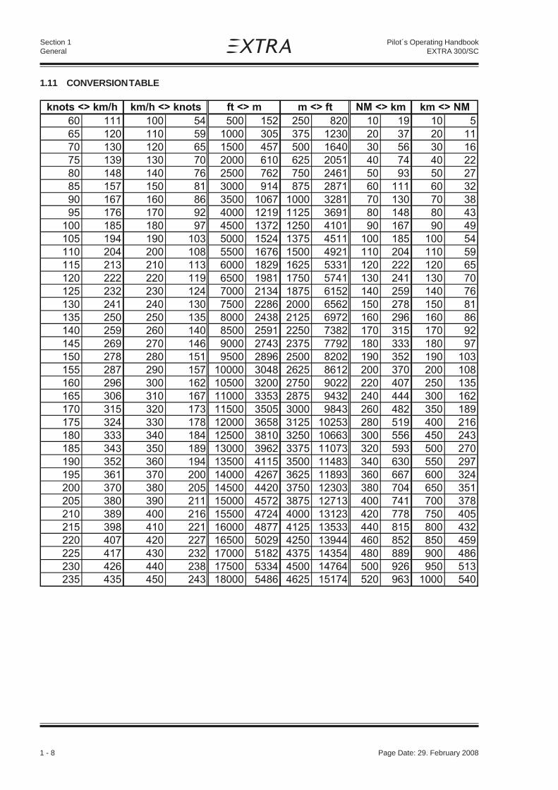
1.11 CONVERSION TABLE
Page Date: 29. February 2008 2 - 1
Pilot´s Operating HandbookEXTRA 300/SC
Section 2Limitations
SECTION 2
LIMITATIONS
Table of Contents
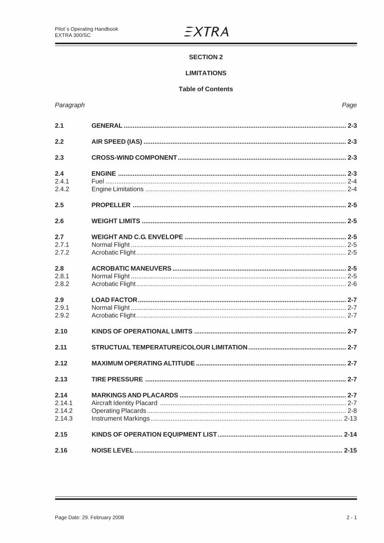
Paragraph PageSECTION 2 LIMITATIONS
2.1 GENERAL ........................................................................................................................... 2-3
2.2 AIR SPEED (IAS) ................................................................................................................ 2-3
2.3 CROSS-WIND COMPONENT............................................................................................. 2-3
2.4 ENGINE .............................................................................................................................. 2-32.4.1 Fuel ..................................................................................................................................... 2-42.4.2 Engine Limitations ............................................................................................................... 2-4
2.5 PROPELLER ...................................................................................................................... 2-5
2.6 WEIGHT LIMITS ................................................................................................................. 2-5
2.7 WEIGHT AND C.G. ENVELOPE ......................................................................................... 2-52.7.1 Normal Flight ....................................................................................................................... 2-52.7.2 Acrobatic Flight .................................................................................................................... 2-5
2.8 ACROBATIC MANEUVERS ................................................................................................ 2-52.8.1 Normal Flight ....................................................................................................................... 2-52.8.2 Acrobatic Flight .................................................................................................................... 2-6
2.9 LOAD FACTOR................................................................................................................... 2-72.9.1 Normal Flight ....................................................................................................................... 2-72.9.2 Acrobatic Flight .................................................................................................................... 2-7
2.10 KINDS OF OPERATIONAL LIMITS .................................................................................... 2-7
2.11 STRUCTUAL TEMPERATURE/COLOUR LIMITATION...................................................... 2-7
2.12 MAXIMUM OPERATING ALTITUDE ................................................................................... 2-7
2.13 TIRE PRESSURE ............................................................................................................... 2-7
2.14 MARKINGS AND PLACARDS ............................................................................................ 2-72.14.1 Aircraft Identity Placard ....................................................................................................... 2-72.14.2 Operating Placards .............................................................................................................. 2-82.14.3 Instrument Markings .......................................................................................................... 2-13
2.15 KINDS OF OPERATION EQUIPMENT LIST..................................................................... 2-14
2.16 NOISE LEVEL................................................................................................................... 2-15

2 - 2 Page Date: 29. February 2008
Pilot´s Operating HandbookEXTRA 300/SC
Section 2Limitations
Left blank intentionally

Page Date: 29. February 2008 2 - 3
Pilot´s Operating HandbookEXTRA 300/SC
Section 2Limitations
SECTION 2
LIMITATIONS
2.1 GENERAL
This section includes operating limitations, instrument markings, and basic placardsnecessary for the safe operation of the aircraft, its engine, standard systems, and standardequipment. The limitations included in this section have been approved by the EASA.Observance of these operating limitations is required by national aviation regulations.
In case of the EXTRA 300/SC is equipped with specific options additional informationrequired for safe operation will be contained in Section 9 "Supplements".
EASA Approcal No.: EASA.A.C.08679
Any exceedance of given limitations have to be reported by the pilot and considered bycorresponding maintenance or inspection procedure according to MAINTENANCE MANUALEXTRA 300/SC.
2.2 AIR SPEED (IAS)
Never Exceed Speed VNE 219 knots (406 km/h)Max. Structural Cruising Speed VNO 154 knots (285 km/h)Maneuver speed (Acrobatic Cat.) VA 154 knots (285 km/h)
(Normal Cat.) VA 138 knots (256 km/h)
2.3 CROSS-WIND COMPONENT
Max. demonstrated cross-wind component for take-off and landing is 15 knots (27 km/h).
2.4 ENGINE
Engine-type Textron-Lycoming Lycoming AEIO-580-B1A with rated maximum 315 HP @2700 RPM.
NOTE
2 - 4 Page Date: 29. February 2008
Pilot´s Operating HandbookEXTRA 300/SC
Section 2Limitations
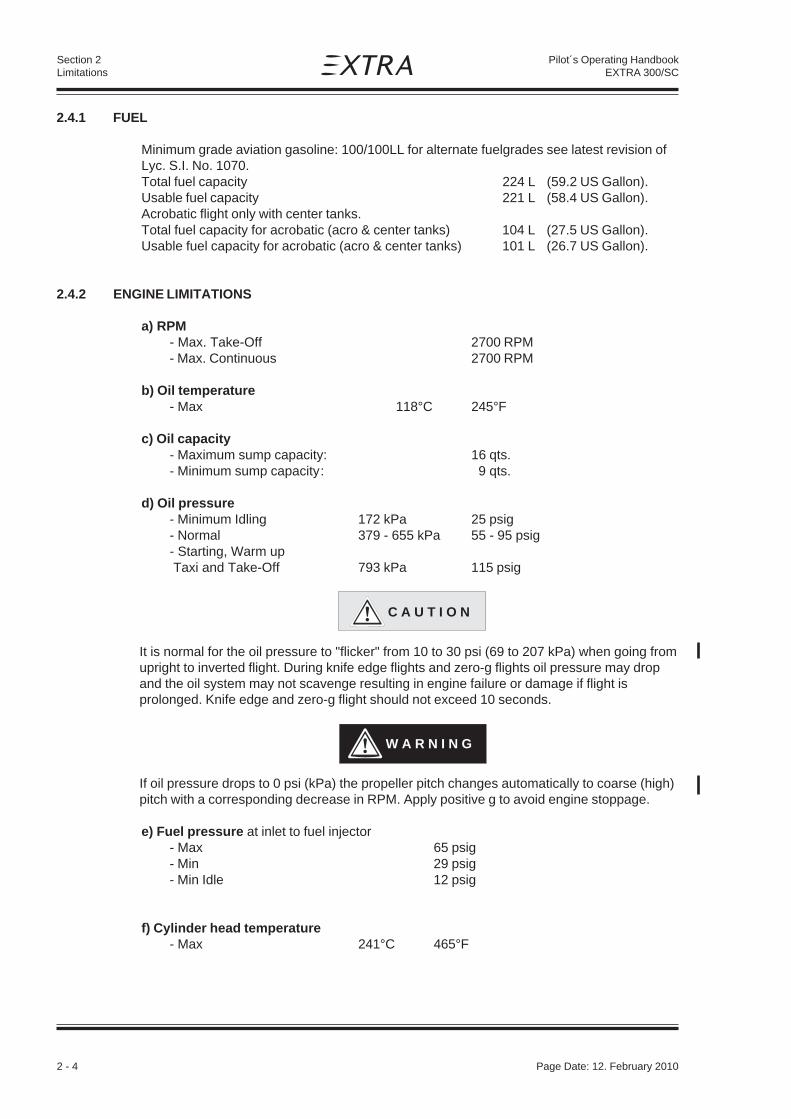
2.4.1 FUEL
Minimum grade aviation gasoline: 100/100LL for alternate fuelgrades see latest revision ofLyc. S.I. No. 1070.Total fuel capacity 224 L (59.2 US Gallon).Usable fuel capacity 221 L (58.4 US Gallon).Acrobatic flight only with center tanks.Total fuel capacity for acrobatic (acro & center tanks) 104 L (27.5 US Gallon).Usable fuel capacity for acrobatic (acro & center tanks) 101 L (26.7 US Gallon).
2.4.2 ENGINE LIMITATIONS
a) RPM- Max. Take-Off 2700 RPM- Max. Continuous 2700 RPM
b) Oil temperature- Max 118°C 245°F
c) Oil capacity- Maximum sump capacity: 16 qts.- Minimum sump capacity: 9 qts.
d) Oil pressure- Minimum Idling 172 kPa 25 psig- Normal 379 - 655 kPa 55 - 95 psig- Starting, Warm up Taxi and Take-Off 793 kPa 115 psig
C A U T I O N
It is normal for the oil pressure to "flicker" from 10 to 30 psi (69 to 207 kPa) when going fromupright to inverted flight. During knife edge flights and zero-g flights oil pressure may dropand the oil system may not scavenge resulting in engine failure or damage if flight isprolonged. Knife edge and zero-g flight should not exceed 10 seconds.
W A R N I N G
If oil pressure drops to 0 psi (kPa) the propeller pitch changes automatically to coarse (high)pitch with a corresponding decrease in RPM. Apply positive g to avoid engine stoppage.
e) Fuel pressure at inlet to fuel injector- Max 65 psig- Min 29 psig- Min Idle 12 psig
f) Cylinder head temperature- Max 241°C 465°F
Page Date: 12. February 2010

Page Date: 29. February 2008 2 - 5
Pilot´s Operating HandbookEXTRA 300/SC
Section 2Limitations
2.5 PROPELLER
MT-Propeller Entwicklung GmbH, Federal Republic of Germanya) Standard: MTV-9-B-C/C198-25, 3-blade constant speedb) Alternative: MTV-14-B-C/C190-130, 4-blade constant speed
Maximum rotational speed- Take-Off and Maximum Continuous: 2600 rpm*
N O T E*
RPM limitation due to compliance with applicable noise protection requirements(ICAO Annex 16 and FAR 36). However for non-US registered airplanes an enhancedrotational speed limitation of 2700 RPM may be permissable when registered in theAcrobatic Category only as ICAO Annex 16 grants an exception for airplanesspecially designed for acrobatic purposes.
2.6 WEIGHT LIMITS
Max. allowed empty weight:- Acrobatic category 620 kg (1367 lbs)- Normal category 624 kg (1376 lbs)
Max. allowed T/O weight:- Acrobatic category 780 kg (1720 lbs)- Normal category 870 kg (1918 lbs)
Max allowed landing weight:- Acrobatic category 780 kg (1720 lbs)- Normal category 870 kg (1918 lbs)
2.7 WEIGHT AND C.G. ENVELOPE
Vertical reference = fire-wall.Horizontal reference = upper longerons in cockpit.
2.7.1 NORMAL FLIGHT
forward C.G. rear C.G.820 kg (1808 lbs) 780 kg (1720 lbs)or below: 53.7 cm (21.1") or below: 66.8 cm (26.3")870 kg (1918 lbs): 54.5 cm (21.5") 870 kg (1918 lbs): 62.6 cm (24.6")
Straight line variation between points.
2.7.2 ACROBATIC FLIGHT
forward C.G. rear C.G.780 kg (1720 lbs) 780 kg (1720 lbs)or below: 53.7 cm (21.1") or below: 66.8 cm (26.3")
2.8 ACROBATIC MANEUVERS
2.8.1 NORMAL FLIGHT
All acrobatic maneuvers are prohibited except stall, chandelle, lazy eight and turns up to60 degrees bank angle.
Page Date: 02. July 2012

2 - 6 Page Date: 29. February 2008
Pilot´s Operating HandbookEXTRA 300/SC
Section 2Limitations
2.8.2 ACROBATIC FLIGHT
The plane is designed for acrobatics. Inverted flight maneuvers are limited to max 4 min.Recommended basic maneuver entry speeds are listed in the following list:
Recommended entry Maneuvers speeds (IAS) Symbol Remarks
min knots (km/h) max knots (km/h)
Segment:Horizontal Line VS VNE
45°climbing 80 (148) VNE
90° up VA VNE
45° diving VS VNE reduce throttle
90° diving VS VNE reduce throttle
1/4 Loop climb. 100 (185) 190 (352)
Looping 100 (185) 190 (352)
Stall turn 100 (185) 190 (352)
Aileron roll 80 (148) VA full deflection
Snap roll 80 (148) 140 (259)
"Tail slide" 100 (185) 190 (352)
Spin VS
Inverted spin VS
Knife edge >150 (278) < 10 s
Inverted Flight >VS 190 (352) < 4 min
CAUTION
Particular caution must be exercised when performing maneuvers at speeds aboveVA [154 KIAS (285 km/h)]. Large or abrupt control inputs above this speed may imposeunacceptably high loads which exceed the structural capability of the aircraft.
N O T E
For Acrobatic Maneuvers see Section 4. All maneuvers can be performed in positive andnegative flight attitude.

Page Date: 29. February 2008 2 - 7
Pilot´s Operating HandbookEXTRA 300/SC
Section 2Limitations
2.9 LOAD FACTOR
2.9.1 NORMAL FLIGHT
Normal Cat.: + 6 g / - 3 g for MTOW 870 kg (1918 lbs)
2.9.2 ACROBATIC FLIGHT
Acro Cat.: + 10 g / - 10 g for MTOW 780 kg (1720 lbs)
2.10 KINDS OF OPERATIONAL LIMITS
Only VFR flights at day are allowed. The A/C may be operated at OAT from -20°C (-4°F) to+38°C (100°F). Flight in known icing-conditions is prohibited. Flights close to thunderstormsare prohibited. Smoking is prohibited.
2.11 STRUCTUAL TEMPERATURE/COLOUR LIMITATION
Structure is qualified up to 72°C (161,6°F). Structure temperatures (composite) above 72°C(161,6°F) are not permitted. In order not to exceed this temperature limit, color specificationfor composite structure (manufacturer document EA-03205.19) has to be complied with.
2.12 MAXIMUM OPERATING ALTITUDE
Max. certified operating altitude is 10,000 ft MSL (3048 m).
2.13 TIRE PRESSURE
The tire pressure is 2620 hpa (38 psi).
2.14 MARKINGS AND PLACARDS
2.14.1 AIRCRAFT IDENTITY PLACARD
*)The latest national aviation regulations must be observed in determining whether theplacard is required.**) call sign placard
EXTRAFLUGZEUGPRODUKTIONS-UND VERTRIEBS-GMBHMODEL: EXTRA 300/SCSERIAL NUMBER:
TC-NUMBER: *
*/**

2 - 8 Page Date: 29. February 2008
Pilot´s Operating HandbookEXTRA 300/SC
Section 2Limitations
2.14.2 OPERATING PLACARDS
or
(near the airspeed indicator)
(in the cockpit)
(on the instrument panel)
(near each filler cap)
(on the seperate hatch / upper cowling)
(Next to the trim switch) or
(Next to the trim switch) (On the control stick grip)
(On the instrument panel on the trim LED indicator)
The markings and placards installed in this airplane contain operating limitations which must be complied with when operating this airplane in the acrobatic category. Other limitations which must be complied with when operating this airplane in this category or in the normal category are contained in the airplane flight manual.
This airplane is certified for VFR dayoperation. Operation under known
icing conditions or close to thunderstorms is prohibited.
OIL
TRIMDOWN
UP
ELEV. TRIMDOWN
UP
V = 154 KTS (ACRO)V = 138 KTS (NORMAL)
A
A
V = 285 km/h (ACRO)V = 256 km/h (NORMAL)
A
A
Page Date: 02. July 2012
F U E LAVGAS 100/100LL

Page Date: 29. February 2008 2 - 9
Pilot´s Operating HandbookEXTRA 300/SC
Section 2Limitations
(in cockpit next to fuel selector)
(On the instrument panel beneath wing tank fuel capacity indicator)
(On the instrument panel beneath center tank fuel capacity indicator)
(On the instrument panel beneath the acro & center tanks fuel capacity indicators)
(In cockpit)
(In cockpit)
(In cockpit)
(On the right side of instrument panel)
FUEL SELECTOR VALVEWING TANK
120 L usable (31.7 US GAL)
OFF
ACRO&
CENTERTANKS
101 L usable(26.7 US GAL)
ACROBATIC: +10G / -10G MTOW 780KG (1720LBS)
NORMAL: 6G / -3G MTOW 870KG (1918LBS)ACROBATICS INCL. SPINNOT APPROVED!
WING TANKMUST BE EMPTY FOR ACROBATICS.USABLE FUEL 120L (31.7 US GAL).
CENTER TANK INDICATIONSHOWS "ZERO" IN LEVEL FLIGHT
BELOW 9 L (2.37 US GAL).UNUSABLE FUEL 3 L (0.8 US GAL).
NO SMOKING

2 - 10 Page Date: 29. February 2008
Pilot´s Operating HandbookEXTRA 300/SC
Section 2Limitations
(On RPM control in the cockpit)
(On mixture control in the cockpit)
(Near throttle control in the cockpit)
(Near canopy locking handles in the cockpit)
(Near the eyeball-type adjustable vents)
(In cockpit)
(In cockpit)
(In cockpit)
(Near Mag. Dir. Indicator)
LOW RPM PROP HIGH RPM
CLOSE THROTTLE OPEN
VENTOPEN
CAUTIONParticular caution must be exercised when performing maneuvers at speeds above V . Large or abrupt control inputs above this speed may impose unacceptably high loads which exceed the structural capability of the aircraft.
A
NO EA 300/SC
CALLSIGN
For
For
Steer
Steer
N 030 060 E 120 150
S 210 240 W 300 330
RICH MIXTURE LEAN
CANOPY LOCK
LOCK UNLOCK
Page Date: 02. July 2012

Page Date: 29. February 2008 2 - 11
Pilot´s Operating HandbookEXTRA 300/SC
Section 2Limitations
(Near the LH drain valve in the bottom fuselage cover)
(Near the RH drain valve in the bottom fuselage cover)
(Near the drain valve on the RH lower side of the firewall)
(On the inside of the separate hatch / upper cowling)
(On the outside of the wheelpants)
(Near opening in middle of bottom fuselage cover)
(In the cockpit, on the aileron control rods)
(In cockpit, on the RH side)
WING TANK DRAIN
CENTER TANK DRAIN
GASCOLATOR DRAIN
USE STRAIGHT MINERAL OILFOR A MINIMUM OF 50 HOURS
2.6 BAR38 PSI
TORQUE TUBELUBRICATION
/ / / / / / / / NO STEP! \ \ \ \ \ \ \ \
MICRO
PHONES

2 - 12 Page Date: 29. February 2008
Pilot´s Operating HandbookEXTRA 300/SC
Section 2Limitations
or
(In cockpit)
Maneuvers Airspeeds Maneuvers Airspeedsmin max min max
Segment:
Horizontal Line V V Aileron roll 148
45°climbing 148 km/h V Snap roll 148 259
90° up V "Tail-slide" 185 352
45° diving V V Spin V ----
90° diving V V Inverted spin V ----
1/4 Loop climb. 185 352 Inverted flight > V 352(Less than 4 min)
Loop 185 352Knife edge >278 ----
Stall turn 185 352 (Less than 10 s)
S NE
NE
NE
S NE S
S NE S
S
km/h V
km/h km/h
V km/h km/h
km/h km/h km/h
km/h km/h km/h
km/h km/h
A
A
Approved acrobatic maneuvers and recommended entry airspeeds
Maneuvers Airspeeds Maneuvers Airspeedsmin KIAS max KIAS min KIAS max KIAS
Segment:
Horizontal Line V V Aileron roll 80
45°climbing 80 V Snap roll 80 140
90° up V V "Tail-slide" 100 190
45° diving V V Spin V ----
90° diving V V Inverted spin V ----
1/4 Loop climb. 100 190 Inverted flight > V 190(Less than 4 min)
Loop 100 190Knife edge >150 ----
Stall turn 100 190 (Less than 10 s)
S NE
NE
A NE
S NE S
S NE S
S
VA
Approved acrobatic maneuvers and recommended entry airspeeds

Page Date: 29. February 2008 2 - 13
Pilot´s Operating HandbookEXTRA 300/SC
Section 2Limitations
2.14.3 INSTRUMENT MARKINGS
AIRSPEED INDICATOR
green arc 64 KIAS (119 km/h) - 154 KIAS (285 km/h)yellow arc 154 KIAS (285 km/h) - 219 KIAS (406 km/h)red line 219 KIAS (406 km/h)
OIL PRESSURE INDICATOR
NOTEOil pressure indicator shows psig values even when labelled 'Psi'.Range markings depending on instrument installed.red line 25 psigyellow arc 25 psig - 55 psiggreen arc 55 psig - 95 psig or 55 psig - 90 psigyellow arc 95 psig - 115 psig or 90 psig - 100 psigred line 115 psig or 100 psig
OIL TEMPERATURE INDICATOR
yellow arc < 140 °Fgreen arc 140 °F - 210 °Fyellow arc 210 °F - 245 °Fred line 245 °F
CYLINDERHEAD TEMPERATURE INDICATOR
yellow arc < 150 °Fgreen arc 150 °F - 435 °Fyellow arc 435 °F - 465 °Fred line 465 °F
RPM INDICATOR (Digital)
green LED 700 RPM - 2400 RPMyellow LED 2400 RPM - 2600 RPM or 2400 RPM - 2700 RPMred LED 2600 RPM - 3500 RPM or 2700 RPM - 3500 RPM
G-METER (Mechanical)
green arc -5g - +8gyellow arc +8g - +10gred line +10g
FUEL FLOW INDICATOR
green arc 0 gal / h - 35 gal / hred radial 35 gal / h
MANIFOLD PRESSURE INDICATOR
Range markings depending on instrument installed.green arc 10 "Hg - 25 "Hg or 10"Hg - 30 "Hgyellow arc 25 "Hg - 29.5 "Hg —red radial 29.5 "Hg —
45° diving V V Spin V ----
Maneuvers Airspeeds Maneuvers Airspeeds
45° diving V V Spin V ----
Page Date: 4. March 2016

2 - 14 Page Date: 29. February 2008
Pilot´s Operating HandbookEXTRA 300/SC
Section 2Limitations
2.15 KINDS OF OPERATION EQUIPMENT LIST
The aircraft may be operated in day-VFR when the appropriate equipment is installed andoperable. No Pilot's Operating Handbook Supplement grants approval for IFR operation. Flightin icing conditions is prohibited.
The following equipment list identifies the systems and equipment upon which certificationwas predicated.The following systems and items of equipment must be installed and operable for theparticular kind of operation indicated.
NORMAL ACROBATICCOMMUNICATION
1. Transceiver-VHF 1 1
ELECTRICAL POWER
1. Battery 1 12. Alternator 1 13. Ampermeter 1 1
FLIGHT CONTROL SYSTEM
1. Elevator-trim control (electric) 1 1
FUEL
1. Boost pump 1 12. Fuel quantity indicator (front center tank) 1 13. Fuel quantity indicator (rear center tank) 1 14. Fuel quantity indicator (wing tank) 1 15. Manifold pressure 1 16. Fuel flow indicator 1 17. Fuel pressure 0 0
LIGHT
1. Wing-tip position/strobe light * *
NAVIGATION
1. Altimeter 1 12. Airspeed indicator 1 13. Mag. direction indicator 1 14. Transponder1 1 1
1) In some airspaces Mode S Elementary Surveillance functionality is required
Page Date: 02. July 2012

Page Date: 29. February 2008 2 - 15
Pilot´s Operating HandbookEXTRA 300/SC
Section 2Limitations
NORMAL ACROBATIC
ENGINE CONTROL
1. RPM indicator 1 12. Exhaust gas temperature ind. 0 03. Cylinder head temperature ind. 0 0
OIL
1. Oil temperature indicator 1 12. Oil pressure indicator 1 1
FLIGHT CREW EQUIPMENT
1. Parachute 0 */**2. Seat belt 1 13. Headset 1 1
NOTE
The zeros ( 0 ) used in the above list mean that either the equipment or system, or both werenot required for type certification.
Other equipment or systems in addition to those listed above may be required by the nationaloperating regulations.
*)The asterisk used in the above list means that latest national aviation regulations must beobserved in determining whether the equipment and/or system is required.**) According FAR Part 91 „General Operating and Flight Rules" each occupant of an USregistered airplane must wear an approved parachute when performing acrobaticmaneuvers. Extra Flugzeugproduktions- und Vertriebs- GmbH considers acrobatics withoutwearing an approved parachute to be unsafe.
2.16 NOISE LEVEL
a) EASA approved noise level for MTV-9-B-C/C198-25 @2600RPM : 76.3 dB(A)The noise level has been established with the standard Gomolzig (6 in 1) exhaust system incl.silencer (EA300-606000) in accordance with ICAO Annex 16, Volume I, Part II, Chapter X, 4thEdition July 2005.
b) EASA approved noise level for MTV-14-B-C/C190-130 @2600RPM: 72.7 dB(A)The noise level has been established with the standard Gomolzig (6 in 1) exhaust system incl.silencer (EA300-606000) in accordance with ICAO Annex 16, Volume I, Part II, Chapter X, 5thEdition July 2008.
No determination has been made by the EASA for the FAA that the noise levels of thisairplane are or should be acceptable or unacceptable for operation at, into, or out any airport.
Page Date: 02. July 2012

2 - 16 Page Date: 29. February 2008
Pilot´s Operating HandbookEXTRA 300/SC
Section 2Limitations
Left blank intentionally

Page Date: 29. February 2008 3 - 1
Section 3Emergency Procedures
Pilot´s Operating HandbookEXTRA 300/SC
SECTION 3
EMERGENCY PROCEDURES
Table of Contents
Paragraph PageSECTION 3 EMERGENCY PROCEDURES
3.0 INTRODUCTION................................................................................................................. 3-33.0.1 General ............................................................................................................................... 3-33.0.2 General Behaviour In Emergency Situations ....................................................................... 3-3
3.1 AIRSPEEDS FOR EMERGENCY OPERATION .................................................................. 3-4
3.2 OPERATIONAL CHECKLIST ............................................................................................. 3-43.2.1 Engine Failure during Take-off Roll ...................................................................................... 3-43.2.2 Engine Failure immediately after Take-off ............................................................................ 3-43.2.3 Engine Failure during Flight (Restart Process) .................................................................... 3-43.2.4 Oil System Malfunction ........................................................................................................ 3-53.2.5 Alternator Failure ................................................................................................................. 3-5
3.3 FORCED LANDINGS.......................................................................................................... 3-53.3.1 Emergency Landing without Engine Power ......................................................................... 3-53.3.2 Precautionary Landing with Engine Power........................................................................... 3-6
3.4 FIRES .................................................................................................................................... 63.4.1 During Start on Ground........................................................................................................ 3-63.4.2 If Engine Fails to Start ......................................................................................................... 3-73.4.3 Engine Fire in Flight ............................................................................................................. 3-7
3.5 ICING .................................................................................................................................. 3-73.5.1 Inadverted Icing Encounter .................................................................................................. 3-7
3.6 UNINTENTIONAL SPIN ...................................................................................................... 3-7
3.7 MANUAL BAIL-OUT ........................................................................................................... 3-7
3.8 EMERGENCY EXIT AFTER TURN OVER .......................................................................... 3-8
3.9 ELEVATOR CONTROL FAILURE ....................................................................................... 3-8

3 - 2 Page Date: 29. February 2008
Section 3Emergency Procedures
Pilot´s Operating HandbookEXTRA 300/SC
Left blank intentionally

Page Date: 29. February 2008 3 - 3
Section 3Emergency Procedures
Pilot´s Operating HandbookEXTRA 300/SC
SECTION 3
EMERGENCY PROCEDURES
3.0 INTRODUCTION
3.0.1 GENERAL
This section contains the checklist and procedures coping with emergencies that mayoccur. This checklist must be followed in various emergencies to ensure maximum safetyfor the pilot and/or aircraft.
Thorough knowledge of these procedures will enable the pilot to better cope with anemergency. The steps should be performed in the listed sequence. However theprocedures do not restrict the pilot from taking any additional action necessary to deal withthe emergency.
3.0.2 GENERAL BEHAVIOUR IN EMERGENCY SITUATIONS
In any emergency situation, contact should be established with a ground station as soon aspossible after completing the initial corrective action. Include position, altitude, heading,speed, nature of the emergency and pilot's intentions in the first transmission. There afterthe ground station should be kept informed of the progress of the flight and of any changesor developments in the emergency. Three basic rules apply to most emergencies andshould be observed by each aircrew member:
1. Maintain aircraft control2. Analyze the situation and take proper action3. Land as soon as possible/as soon as practical
The meaning of "as soon as possible" and "as soon as practical" as used in this section isas follows:
Land AS SOON AS POSSIBLE (ASAP) = Emergency conditions are urgent and requirean immediate landing at the nearest suitableairfield, considering also other factors, such asweather conditions and aircraft mass.
Land AS SOON AS PRACTICAL = Emergency conditions are less urgent and inthe aircrews judgement the flight may besafely continued to an airfield where moreadequate facilities are available.
WARNING
Make only one attempt to restore an automatically disconnected power source orreset or replace an automatically disconnected CPD (circuit protection device) thataffects flight operations or safety. Each successive attempt to restore anautomatically disconnected power source, or the resetting of an automaticallydisconnected CPD can result in progressively worse effects.

3 - 4 Page Date: 29. February 2008
Section 3Emergency Procedures
Pilot´s Operating HandbookEXTRA 300/SC
3.1 AIRSPEEDS FOR EMERGENCY OPERATION
Stall speed 64 KIAS (119 km/h)
Engine failure after take-off 90 KIAS (167 km/h)
Best recommended gliding speed ( glide angle 1 : 6,2 )-Acrobatic cat. (780 kg (1720 lbs)) 90 KIAS (167 km/h)
-Normal cat. (870 kg (1918 lbs)) 90 KIAS (167 km/h)
Precautionary landing with engine power 90 KIAS (167 km/h)
Landing without engine power 90 KIAS (167 km/h)
Maximum demonstrated cross wind component 15 Knots (27 km/h)
3.2 OPERATIONAL CHECKLIST
3.2.1 ENGINE FAILURE DURING TAKE-OFF ROLL
1. Throttle IDLE2. Brakes APPLY3. Mixture IDLE CUT OFF4. Ignition switch OFF5. Master switch OFF
3.2.2 ENGINE FAILURE IMMEDIATELY AFTER TAKE-OFF
Stall speed 61 KIAS
1. Airspeed 90 KIAS (167 km/h)2. Mixture IDLE CUT OFF3. Fuel selector valve OFF (Pull & Turn)4. Ignition switch OFF5. Master switch OFF6. Forced landing PERFORM AS PRACTICABLE
3.2.3 ENGINE FAILURE DURING FLIGHT (RESTART PROCESS)
1. Aircraft attitude UPRIGHT2. Airspeed 90 KIAS (167 km/h)3. Fuel quantity indicators CHECK4. Fuel selector valve SELECT TANK with highest fuel level5. Mixture RICH6. Boost pump ON7. Ignition switch BOTH
(or START if propeller has stopped)

Page Date: 29. February 2008 3 - 5
Section 3Emergency Procedures
Pilot´s Operating HandbookEXTRA 300/SC
3.2.4 OIL SYSTEM MALFUNCTION
If oil pressure indicates low: Apply positive "g"If oil pressure is not regained than:1. Airspeed 90 KIAS (167 km/h)2. Throttle REDUCE TO IDLE3. Engine oil temperature OBSERVE INDICATION4. Land ASAP
WARNING
If oil pressure drops to 0 psi the propeller pitch changes automatically to coarse(high) pitch with a corresponding decrease in RPM.
3.2.5 ALTERNATOR FAILURE
I. Red alternator warning light illuminates:
1. Ammeter indication CHECK
if indication is negative:2. Land ASAP
an overvoltage situation has occuredbattery is the only power source
if indication is positive:2. Land AS SOON AS PRACTICAL
red alternator warning light is defective3. Ammeter MONITOR
II. Ammeter has negative indication:
1. RPM INCREASE or electrical load REDUCE
if ammeter indication is still negative2. Land ASAP
battery is the only power source
III. ALT OUTPUT circuit breaker has tripped (ammeter indication negative):
1. ALT OUTPUT circuit breaker RESET
if ALT OUTPUT circuit breaker trips again:2. Land ASAP
battery is the only power source
3.3 FORCED LANDINGS
3.3.1 EMERGENCY LANDING WITHOUT ENGINE POWER
1. Seat belts, shoulder harnesses SECURE2. Airspeed 90 KIAS (167 km/h)3. Mixture IDLE CUT OFF4. Fuel selector valve OFF (Pull & Turn)

3 - 6 Page Date: 29. February 2008
Section 3Emergency Procedures
Pilot´s Operating HandbookEXTRA 300/SC
5. Ignition switch OFF6. Master switch OFF7. Touchdown SLIGHTLY TAIL LOW8. Brakes OPTIMUM BRAKING
3.3.2 PRECAUTIONARY LANDING WITH ENGINE POWER
1. Seat belt, shoulder harness SECURE2. Airspeed 90 KIAS (167 km/h)3. Selected field FLY OVER,
noting terrain andobstructions, thenreaching a safealtitude and airspeed
4. Master switch OFF5. Touchdown SLIGHTLY TAIL LOW6. Ignition switch OFF7. Mixture IDLE CUT OFF8. Fuel selector valve OFF (Pull & Turn)9. Brakes APPLY HEAVILY
3.4 FIRES
3.4.1 DURING START ON GROUND
1. Cranking CONTINUE to get a startwhich would suck theflames and accumulatedfuel through the airinlet and into the engine.
2. Fuel selector valve OFF (Pull & Turn)
3. Power 1700 RPM for one minute.
4. Engine SHUT DOWN
5. After engine stop ABANDON aircraft andinspect for damage
6. Fire EXTINGUISH using fireextinguisher if available
WARNING
Do not open engine compartment access doorswhile engine is on fire!

Page Date: 29. February 2008 3 - 7
Section 3Emergency Procedures
Pilot´s Operating HandbookEXTRA 300/SC
3.4.2 IF ENGINE FAILS TO START
1. Cranking CONTINUE2. Throttle FULL OPEN3. Mixture IDLE CUT OFF4. Fuel selector valve OFF (Pull & Turn)
If fire is extinguished
5. Master switch OFF6. Ignition switch OFF7. Engine compartment INSPECT
3.4.3 ENGINE FIRE IN FLIGHT
1. Mixture IDLE CUT OFF2. Fuel selector valve OFF (Pull & Turn)3. Master switch OFF4. Airspeed 90 KIAS (167 km/h), find your
airspeed/attitudewhich will keep thefire away from the cockpit
5. Land AS SOON AS POSSIBLE
3.5 ICING
3.5.1 INADVERTED ICING ENCOUNTER
1. Turn back or change altitude to obtain an outside temperature that is less conductive toicing.
2. Plan a landing at the nearest airfield. With extremely rapid ice build-up select asuitable "off airport" landing field.
3.6 UNINTENTIONAL SPIN
Refer to section 4 (Normal Procedures) acrobatic maneuver, spin recovery
3.7 MANUAL BAIL-OUT
When in an emergency situation that requires abandoning the aircraft and while wearing aparachute, which is at least strongly recommended for acrobatics:
- Reduce speed to 90 Kts (167 km/h) if possible- Pull mixture to lean- Open canopy (push forward if applicable)- Take off headset- Open seat belt- Leave airplane to the left side- Try to avoid wing and tail- Open parachute

3 - 8 Page Date: 29. February 2008
Section 3Emergency Procedures
Pilot´s Operating HandbookEXTRA 300/SC
3.8 EMERGENCY EXIT AFTER TURN OVER
1. Master switch OFF2. Fuel selector valve OFF (Pull & Turn)3. Seat belts OPEN4. Parachute harnesses OPEN5. Canopy handle PULL TO OPEN
WARNING
If canopy fails to open break the canopy.
6. Aircraft EVACUATE ASAP
3.9 ELEVATOR CONTROL FAILURE
In case of elevator control failure the aircraft can be flown with the elevator trim.In this case trim nose up to the desired speed and control horizontal flight or descend withengine power.For landing trim nose up and establish a shallow descend by adjusting throttle. To flair theplane gently increase power to bring the nose up to landing attitude.

Page Date: 29. February 2008 4 - 1
Section 4Normal Procedures
Pilot´s Operating HandbookEXTRA 300/SC
SECTION 4
NORMAL PROCEDURES
Table of Contents
Paragraph PageSECTION 4 NORMAL PROCEDURES
4.0 GENERAL ........................................................................................................................... 4-34.0.1 Airspeeds for Operation ...................................................................................................... 4-34.0.2 Checklist and Procedures ................................................................................................... 4-3
4.1 PREFLIGHT INSPECTION ................................................................................................. 4-44.1.1 Exterior Inspection Illustration.............................................................................................. 4-44.1.2 General ................................................................................................................................ 4-4
4.2 CHECKLIST PROCEDURES ............................................................................................... 4-4
4.3 STARTING PROCEDURES.................................................................................................. 4-64.3.1 Cold Engines ....................................................................................................................... 4-64.3.2 Hot Engines ......................................................................................................................... 4-6
4.4 TAXIING THE AIRCRAFT .................................................................................................... 4-6
4.5 TAKE-OFF PROCEDURE..................................................................................................... 4-74.5.1 Before Take-off ..................................................................................................................... 4-74.5.2 Take-off ................................................................................................................................ 4-7
4.6 CLIMB ................................................................................................................................. 4-8
4.7 CRUISE ............................................................................................................................... 4-8
4.8 LANDING PROCEDURES ................................................................................................... 4-84.8.1 Descent ............................................................................................................................... 4-84.8.2 Approach ............................................................................................................................. 4-84.8.3 Before Landing ..................................................................................................................... 4-94.8.4 Normal Landing .................................................................................................................... 4-9
4.9 GO-AROUND ....................................................................................................................... 4-9
4.10 SHUTDOWN........................................................................................................................ 4-9
4.11 LEAVING THE AIRCRAFT ................................................................................................. 4-10
4.12 ACROBATIC MANEUVERS ............................................................................................... 4-104.12.1 General .............................................................................................................................. 4-104.12.2 Maneuvers ......................................................................................................................... 4-104.12.3 Spin ................................................................................................................................... 4-12
Page Date: 02. July 2012

4 - 2 Page Date: 29. February 2008
Section 4Normal Procedures
Pilot´s Operating HandbookEXTRA 300/SC
Left blank intentionally

Page Date: 29. February 2008 4 - 3
Section 4Normal Procedures
Pilot´s Operating HandbookEXTRA 300/SC
SECTION 4
NORMAL PROCEDURE
4.0 GENERAL
4.0.1 AIRSPEEDS FOR OPERATION
870 KG 780 KG(1918 LBS) (1727 LBS)KIAS (km/h) KIAS (km/h)
Start:Rotating Speed 70 (130) 67 (124)
Climb:VX 91 (169) 86 (159)
VY 100 (185) 95 (176)
Recommended NormalClimb Speed 106 (196) 101 (187)
Max. Cruise Speed 183 (339) 187 (346)
Landing:
Approach 85 (157) 81 (150)
On Final 85 (157) 81(150)
Go-Around Speed 95 (176) 91(169)
Recommended Airspeed (maximum)For Flight In Rough Air (VNO) 154 (285) 146 (270)
Max. Demonstrated CrossWind Component 15 Kts (27) 15 Kts (27)
4.0.2 CHECKLIST AND PROCEDURES
This handbook contains the checklist and procedures to operate the aircraft. The pilotshould be familiar with all procedures contained in this Pilot's Operating Handbook, whichmust be carried on board. The pilot has to comply with Checklist for daily check andinspections (see Section 8, Handling, Servicing and Maintenance).

4 - 4 Page Date: 29. February 2008
Section 4Normal Procedures
Pilot´s Operating HandbookEXTRA 300/SC
4.1 PREFLIGHT INSPECTION
4.1.1 EXTERIOR INSPECTION ILLUSTRATION
4.1.2 GENERAL
Visually check airplane for general condition during walk around inspection.Perform exterior check as outlined in the picture above in counterclockwise direction.
4.2 CHECKLIST PROCEDURES
1) Cockpit
1. Pilot's Operating Handbook (AVAILABLE)2. Airplane weight and balance CHECKED3. Ignition switch OFF4. Master switch ON5. Fuel quantity indicator front center tank CHECK6. Fuel quantity indicator rear center tank CHECK
NOTE
Ensure at least one center tank having enough fuel for take-off, landing andgo-around.
7. Fuel quantity indicator wing tank CHECK8. Master switch OFF9. Fuel selector * ACRO & CENTER TANKS
*NOTE
Although safe operation does not require the use of the tanks in a specific sequence,it is recommended to set fuel selector to "ACRO & CENTER TANKS" position!
2) Empennage
1. All round inspection, canopy, surfaces,stabilizers, elevator, trim tab, rudder and tailwheel CHECK
2. Horizontal stabilizer attachment bols CHECK FOR FREEPLAY BYMOVING THE TIP OF THEHORIZ. STABILIZER UP- ANDDOWNWARDS
3
2
1
5
4

Page Date: 29. February 2008 4 - 5
Section 4Normal Procedures
Pilot´s Operating HandbookEXTRA 300/SC
3) Right wing
1. Aileron, freedom of movement and security CHECK2. Trailing edge CHECK3. Fuel tank vent opening (right landing gear) CHECK4. Fuel quantity CHECK5. Fuel tank filler cap CHECK6. Right landing gear, wheel and brake CHECK
4) Nose
1. Engine oil dipstick CHECK2. Propeller and spinner CHECK3. Air inlet CHECK4. Fuel tank filler caps (front & rear center, wing) CHECK5. Fuel drain for center & acro and wing tank DRAIN FOR AT LEAST 4
SECONDS TO CLEAR SUMP OFPOSSIBLE WATER;CHECK CLOSED
6. Fuel filter drain DRAIN FOR AT LEAST 4SECONDS TO CLEARFILTER OF POSSIBLE WATER;CHECK CLOSED
5) Left wing
1. Left landing gear, wheel and brakes CHECK2. Fuel quantity CHECK3. Fuel tank filler cap CHECK4. Pitot cover REMOVE5. Trailing edge CHECK6. Aileron, freedom of movement and security CHECK
6) Before starting engine
1. Preflight inspection COMPLETE2. Parachute CHECK SECURED3. Seat, seatbelts, shoulder harnesses ADJUST AND LOCK4. Canopy CLOSE AND LOCK
CAUTION
Handles of the canopy lock mechanism must be in the most opposite position indicated witha red line on the canopy frame. Check gap between canopy frame and fuselage fairing!
5. Brake CHECK6. Master switch ON7. Electrical equipment OFF

4 - 6 Page Date: 29. February 2008
Section 4Normal Procedures
Pilot´s Operating HandbookEXTRA 300/SC
4.3 STARTING PROCEDURES
4.3.1 COLD ENGINES
The following starting procedures are recommended, however, the starting conditions maynecessitate some variation from these procedures.
1. Perform pre-flight inspection.
2. Set propeller governor control in "High RPM" position.
3. Open throttle approximately 1/4 travel.
4. Turn boost pump "ON".
5. Move mixture control to "FULL RICH" until a slight but steady fuel flow is noted(approximately 3 to 5 seconds) and return mixture control to "IDLE CUT-OFF".Turn bost pump "OFF".
6. Engage starter.
7. When engine fires release the ignition switch back to "BOTH".
8. Move mixture control slowly and smoothly to "FULL RICH".
9. Check the oil pressure gauge. If minimum oil pressure is notindicated within 30 seconds, shut off the engine and determine trouble.
4.3.2 HOT ENGINES
Because of the fact that the fuel percolates and the system must be cleared of vapor, it isrecommended to use the same procedure as outlined for cold engine start.
4.4 TAXIING THE AIRCRAFT
1. Canopy CLOSE AND LOCK2. Brake CHECK3. Altimeter Set on QFE or QNH
Scale error max. +60 ft4. Electrical equipment ON5. Radio Set and test6. Mixture Leave in "FULL RICH" position
Operate only with the propeller in minimum blade angle (High RPM).Warm-up at approximately 1000-1200 RPM. The engine is ready for take-off when the throttlecan be opened without the engine faltering.

Page Date: 29. February 2008 4 - 7
Section 4Normal Procedures
Pilot´s Operating HandbookEXTRA 300/SC
4.5 TAKE-OFF PROCEDURE
4.5.1 BEFORE TAKE-OFF
Before you line up at the runway for take-off:
1. Oil pressure and oil temperature CHECK
2. Magnetos CHECK as follows:
Engine RPM: Set to1800 min-1
Pay attation to the three small LEDs in the "Status" area on the upper left corner of thedigital RPM indicator (P-1000) face:
Ignition switch position: LEFTStatus area: Right red LED illuminatesDisplay: Shows RPM drop
Ignition switch position: RIGHTStatus area: Left red LED illuminatesDisplay: Shows RPM drop
Ignition switch position: BOTHStatus area: Right and left red LED remain off
The middle LED is not allowed to alert,otherwise the difference is more thanpermissible.
N O T E
During the short circuit (grounding) of a single magneto, the respective red LEDmust illuminate. The maximal allowed RPM drop at 1800 min-1 is 175 min-1 . Themaximal difference between the magnetos shall not to be more than 50 RPM(identify with the illuminated yellow LED).
3. Alternator Output CHECK Ammeter indication is positive
4. Propeller control MOVE through its complete range tocheck operation and return to fullHIGH RPM position.
5. Boost pump ON (check indicator movement on the fuelflow gauge).
4.5.2 TAKE-OFF
Set throttle smoothly to max. and let the airspeed go up to 65 to 70 KIAS (120 to 130 km/h).A light pressure on the stick lifts the tail to horizontal position. Rotate the aircraft at 70 KIAS(130 km/h). Proceed climbing at recommended climb speed.
Page Date: 02. July 2012
4 - 8 Page Date: 29. February 2008
Section 4Normal Procedures
Pilot´s Operating HandbookEXTRA 300/SC
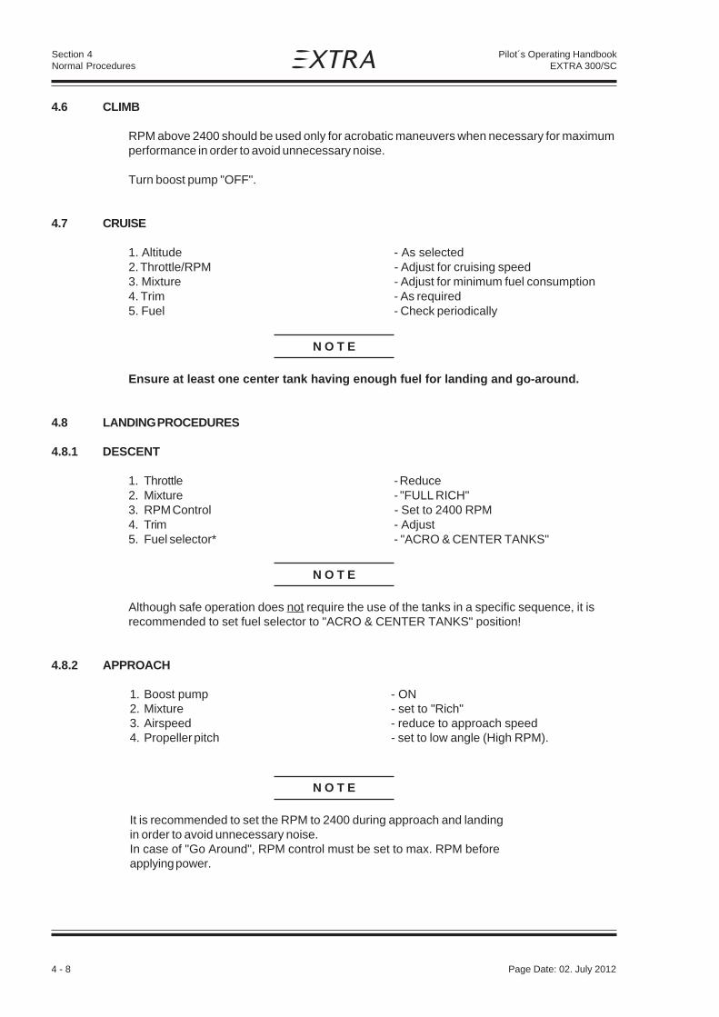
4.6 CLIMB
RPM above 2400 should be used only for acrobatic maneuvers when necessary for maximumperformance in order to avoid unnecessary noise.
Turn boost pump "OFF".
4.7 CRUISE
1. Altitude - As selected2. Throttle/RPM - Adjust for cruising speed3. Mixture - Adjust for minimum fuel consumption4. Trim - As required5. Fuel - Check periodically
N O T E
Ensure at least one center tank having enough fuel for landing and go-around.
4.8 LANDING PROCEDURES
4.8.1 DESCENT
1. Throttle - Reduce2. Mixture - "FULL RICH"3. RPM Control - Set to 2400 RPM4. Trim - Adjust5. Fuel selector* - "ACRO & CENTER TANKS"
N O T E
Although safe operation does not require the use of the tanks in a specific sequence, it isrecommended to set fuel selector to "ACRO & CENTER TANKS" position!
4.8.2 APPROACH
1. Boost pump - ON2. Mixture - set to "Rich"3. Airspeed - reduce to approach speed4. Propeller pitch - set to low angle (High RPM).
N O T E
It is recommended to set the RPM to 2400 during approach and landingin order to avoid unnecessary noise.In case of "Go Around", RPM control must be set to max. RPM beforeapplying power.
Page Date: 02. July 2012

Page Date: 29. February 2008 4 - 9
Section 4Normal Procedures
Pilot´s Operating HandbookEXTRA 300/SC
4.8.3 BEFORE LANDING
1. Landing approach - proceed at 85 KIAS (157 km/h)2. Airspeed on final - maintain 85 KIAS (157 km/h)3. Elevator trim - adjust
N O T E
Stall speed will be
MTOW = 870 kg : 64 KIAS (119 km/h)
4.8.4 NORMAL LANDING
1. Landing - perform as practicablewith respect to surfaceand weather condition
2. Touchdown - 3 point landing
N O T E
The rudder is effective down to 30 KIAS (56 kmh)
3. Throttle - CLOSE / IDLE
4. Braking - Minimum required
4.9 GO-AROUND
Decide early in the approach if it is necessary to go around andthen start go-around before too low altitude and airspeed arereached.
Proceed as follows:
1. RPM control - "HIGH RPM" / Full forward2. Throttle - "OPEN" / Take-off power3. Airspeed - Minimum 90 KIAS (167 km/h)
rotate to go-around altitude
4.10 SHUTDOWN
1. Boost pump - "OFF"2. Engine - Run for 1 min. at 1000 RPM3. Dead cut check - Perform4. Electrical equipment - "OFF"5. Mixture - "IDLE CUT OFF"
Page Date: 02. July 2012

4 - 10 Page Date: 29. February 2008
Section 4Normal Procedures
Pilot´s Operating HandbookEXTRA 300/SC
6. Ignition switch - "OFF"7. Master switch - "OFF"
4.11 LEAVING THE AIRCRAFT
1. Canopy - Close and lock2. Aircraft - Secure3. Pitot cover - Attach4. Log book - Complete
4.12 ACROBATIC MANEUVERS
4.12.1 GENERAL
N O T E
Prior to executing these maneuvers tighten harnesses and check all loose items are stowed.Start the maneuvers at safe altitude and max continuous power setting if nototherwise noted.
For maneuver limits refer to Section 2 LIMITATIONS.
At high negative g-loads and zero g-periods it is normal that oil pressure and RPM indicationmight drop down momentarily returning to normal status at positive g-loads.
WARNING
The high permissible load factors of the airplane may exceed the individual physio-logical limits of pilot. This fact must be considered when pulling or pushing high g's.
4.12.2 MANEUVERS
CAUTION
Particular caution must be exercised when performing maneuvers at speeds aboveVA [158 KIAS (292 km/h)]. Large or abrupt control inputs above this speed may im-pose unacceptably high loads which exceed the structural capability of the aircraft.
Acrobatics is traditionally understood as maneuvers like loop, humpty bump, hammerheadturn, aileron roll etc..
This manual does not undertake to teach acrobatics, however, it is meant to demonstratethe plane's capabilities.
For this reason maneuvers are divided into segments. The segments are described.Limitations are pointed out.
Page Date: 02. July 2012
Page Date: 29. February 2008 4 - 11
Section 4Normal Procedures
Pilot´s Operating HandbookEXTRA 300/SC
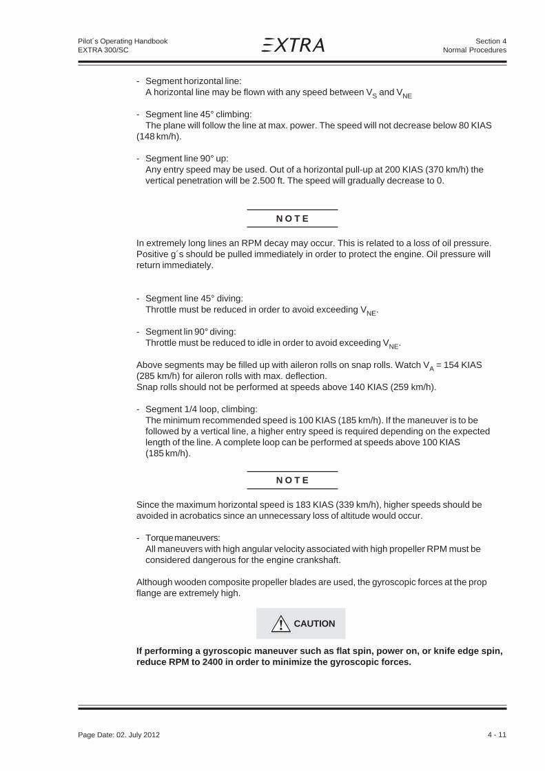
- Segment horizontal line:A horizontal line may be flown with any speed between VS and VNE
- Segment line 45° climbing:The plane will follow the line at max. power. The speed will not decrease below 80 KIAS
(148 km/h).
- Segment line 90° up:Any entry speed may be used. Out of a horizontal pull-up at 200 KIAS (370 km/h) thevertical penetration will be 2.500 ft. The speed will gradually decrease to 0.
N O T E
In extremely long lines an RPM decay may occur. This is related to a loss of oil pressure.Positive g´s should be pulled immediately in order to protect the engine. Oil pressure willreturn immediately.
- Segment line 45° diving:Throttle must be reduced in order to avoid exceeding VNE.
- Segment lin 90° diving:Throttle must be reduced to idle in order to avoid exceeding VNE.
Above segments may be filled up with aileron rolls on snap rolls. Watch VA = 154 KIAS(285 km/h) for aileron rolls with max. deflection.Snap rolls should not be performed at speeds above 140 KIAS (259 km/h).
- Segment 1/4 loop, climbing:The minimum recommended speed is 100 KIAS (185 km/h). If the maneuver is to befollowed by a vertical line, a higher entry speed is required depending on the expectedlength of the line. A complete loop can be performed at speeds above 100 KIAS(185 km/h).
N O T E
Since the maximum horizontal speed is 183 KIAS (339 km/h), higher speeds should beavoided in acrobatics since an unnecessary loss of altitude would occur.
- Torque maneuvers:All maneuvers with high angular velocity associated with high propeller RPM must beconsidered dangerous for the engine crankshaft.
Although wooden composite propeller blades are used, the gyroscopic forces at the propflange are extremely high.
CAUTION
If performing a gyroscopic maneuver such as flat spin, power on, or knife edge spin,reduce RPM to 2400 in order to minimize the gyroscopic forces.
Page Date: 02. July 2012

4 - 12 Page Date: 29. February 2008
Section 4Normal Procedures
Pilot´s Operating HandbookEXTRA 300/SC
4.12.3 SPIN
To enter a spin proceed as follows:
- Reduce speed, power idle- When the plane stalls:
- kick rudder to desired spin direction- hold ailerons neutral- stick back (positive spinning), Stick forward (negative spinning)
The plane will immediately enter a stable spin.
- Ailerons against spin direction will make the spin flatter.- Ailerons into spin direction will lead to a spiral dive.
Above apply for positive and negative spinning.
To stop the spin:
- Apply opposite rudder- Make sure, power idle- Hold ailerons neutral- Stick to neutral position
After one turn of spinning the plane will recover within about 1/2 turn.After six turns of spinning the plane will recover within about 1 turn.Recovery can still be improved by feeding in in-spin ailerons.
N O T E
If ever disorientation should occur during spins (normal or inverted) one method always worksto stop the spin:
- Power idle- Kick rudder to the heavier side (this will always be against spin direction)- Take hands off the stick
The spin will end after 1/2 thru 1 turn. The plane will be in a steep dive in a side-slip.Recovery to normal flight can be performed easily.
N O T E
After one turn of spinning the altitude loss including recovery is within about 1500 ft.After six turns of spinning the altitude loss including recovery is within about 3300 ft.
Page Date: 02. July 2012

Page Date: 29. February 2008 5 - 1
Section 5Performance
Pilot´s Operating HandbookEXTRA 300/SC
SECTION 5
PERFORMANCE
Table of Contents
Paragraph PageSECTION 5 PERFORMANCE
5.1 GENERAL ........................................................................................................................... 5-35.1.1 Performance Charts ............................................................................................................ 5-35.1.2 Definitions of Terms ............................................................................................................. 5-35.1.3 Sample Problem .................................................................................................................. 5-3
5.2 ISA CONVERSION.............................................................................................................. 5-5
5.3 AIRSPEED CALIBRATION ................................................................................................. 5-6
5.4 STALL SPEED .................................................................................................................... 5-7
5.5 TAKE-OFF PERFORMANCE .............................................................................................. 5-8
5.6 RATE OF CLIMB PERFORMANCE .................................................................................... 5-9
5.7 TIME, FUEL & DISTANCE TO CLIMB .............................................................................. 5-10
5.8 CRUISE SPEED ................................................................................................................ 5-11
5.9 ENDURANCE ................................................................................................................... 5-12
5.10 RANGE ............................................................................................................................. 5-13
5.11 CRUISE PERFORMANCE ................................................................................................ 5-14
5.12 TIME , FUEL & DISTANCE TO DESCEND ....................................................................... 5-15
5.13 LANDING PERFORMANCE ............................................................................................. 5-16

5 - 2 Page Date: 29. February 2008
Pilot´s Operating HandbookEXTRA 300/SC
Section 5Performance
Left blank intentionally

Page Date: 29. February 2008 5 - 3
Section 5Performance
Pilot´s Operating HandbookEXTRA 300/SC
SECTION 5
PERFORMANCE
5.1 GENERAL
Performance data charts on the following pages are presented to facilitate the planning offlights in detail and with reasonable accuracy under various conditions.It should be noted that the performance information presented in the range and endurancecharts allow for 45 minutes reserve fuel at specified conditions. Some indeterminate variab-les such as engine and propeller, air turbulence and others may account for variations ashigh as 10% or more in range and endurance. Therefore, it is important to utilize all availableinformation to estimate the fuel required for the particular flight.
5.1.1 Performance Charts
Performance data are presented in tabular or graphical form to illustrate the effect of diffe-rent variables. Sufficiently detailed information is provided in the tables so that conservativevalues can be selected and used to determine the particular performance figure withreasonable accuracy.All speeds in this chapter are Indicated Air Speeds (IAS). The performance figures beloware given under following conditions:1. Take-off Weight 870 kg (1918 lbs)2. Take-off and landing on concrete surface.3. No wind.4. Standard atmospheric condition.
5.1.2 Definitions of Terms
For definition of terms, abbreviations and symbols refer to section 1, General.
5.1.3 Sample Problem
Except in § 5.6 all examples presented in the performance charts refer to the conditions ofthe sample problem outlined here.
CONDITIONS
Takeoff: Weight (MTOW): 870 kg (1918 lbs)Field Pressure Alt: 2000 ft (610 m)Temperature: 15°CWind Component (Headwind): 10 KTField Length: 3000 ft
Cruise: Total Distance: 400 NMPressure Altitude: 8000 ft (2438 m)Temperature (ISA): -1°C
Landing: Weight: 750 kg (1653 lbs)Field Pressure Alt: 2000 ft (610 m)Temperature: 15°CWind Component (Headwind): 5 KTField Length: 2000 ft

5 - 4 Page Date: 29. February 2008
Pilot´s Operating HandbookEXTRA 300/SC
Section 5Performance
TAKE-OFF
§ 5.5 shows the Take-Off Distance.Example:
T/O Weight: 870 kg (1918 lbs)Ground Roll: 138 m (453 ft)(decreased by 8% due to headwind): 127 m (417 ft)Total Distance to clear a 50 ft obstacle: 298 m (978 ft)(decreased by 8% due to headwind): 274 m (899 ft)
These distances are well within the available field length in this sample problem.
CLIMB
§ 5.6 shows the Rate Of Climb Performance.(conditions outlined in Fig. 5.6 deviate from the sample problem given here).
Pressure altitude: 6000 ftOutside air temperatur: +5°CWeight: 840 kg (1852 lbs)Climb Rate: 1895 ft/min
§ 5.7 shows the Time, Fuel and Distance to Climb.Example (climb from 2000 ft (610 m) to 8000 ft (2438 m)):
Time to Climb: (3.6 - 1.0) min = 2.6 minFuel to Climb: (7.5 - 2.0) Liters = 5.5 Liters (1.45 US Gal.)Distance to Climb: (6.3 - 1.6) NM = 4.7m NM
CRUISE
Cruise Altitude and Power Setting should be determined for most economical fuelconsumption and several other considerations.§ 5.11 shows the Cruise Performance data for a T/O Weight of 870 kg (1918 lbs) withmaximum fuel (224 l).The conditions in the examples of the following Figures are:
Pressure altitude: 8000 ft (2438 m)Power Setting: 65 %
§ 5.8 shows the cruise speed: 166 kts (307 km/h)
§ 5.9 shows the endurance: 3.3 h
§. 5.10 shows the range: 544 NM (1007 km)The desired total distance in this sample problem is well within this value.
DESCENT
§ 5.12 shows Descent Time, Distance and Fuel data.Example (descent from 8000 ft (2438 m) to 2000 ft (610 m)):
Time to Descent : (8 - 2) min = 6 minDistance to Descent : (22.4 - 5) NM = 17.4 NMFuel to Descent : (4 - 1) Liters = 3 Liters (0.79 US Gal.)
Page Date: 29. February 2008 5 - 5
Section 5Performance
Pilot´s Operating HandbookEXTRA 300/SC
LANDING
§ 5.13 shows the Landing Distance.Example:
Landing Weight: 750 kg (1653 lbs)Ground Roll: 166 m (545 ft)(decreased by 15% due to headwind): 141 m (463 ft)Total Distance to clear a 50 ft obstacle: 511 m (1677 ft)(decreased by 15% due to headwind): 434 m (1424 ft)
These distances are well within the available field length in this sample problem.
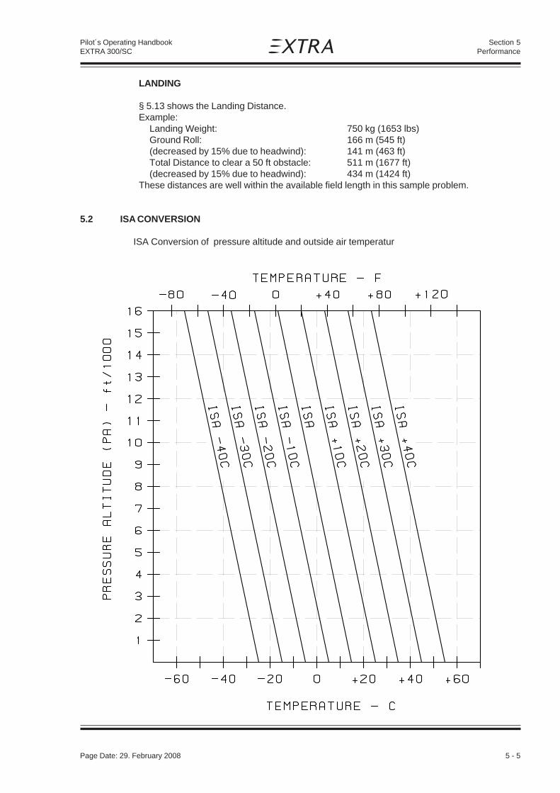
5.2 ISA CONVERSION
ISA Conversion of pressure altitude and outside air temperatur

5 - 6 Page Date: 29. February 2008
Pilot´s Operating HandbookEXTRA 300/SC
Section 5Performance
5.3 AIRSPEED CALIBRATION
NOTE
Indicated airspeed assumes zero instrument error.
50
60
70
80
90
100
110
120
130
140
150
160
170
180
190
200
210
220
50 60 70 80 90 100 110 120 130 140 150 160 170 180 190 200 210 220
KCAS
KIA
S
90
110
130
150
170
190
210
230
250
270
290
310
330
350
370
390
41090 110 130 150 170 190 210 230 250 270 290 310 330 350 370 390 410
CAS [km/h]
IAS
[km
/h]

Page Date: 29. February 2008 5 - 7
Section 5Performance
Pilot´s Operating HandbookEXTRA 300/SC
5.4 STALL SPEED
CONDITION:
POWER IDLEFORWARD C/G STALL SPEEDS
ANGLE OF BANK
WEIGHT CATEGORY 0° 30° 45° 60°1g 1,15 g 1,41 g 2 g
KIAS (km/h) KIAS (km/h) KIAS (km/h) KIAS (km/h)
870 kg NORMAL 64 (119) 69 (128) 77 (143) 91 (169)(1918 lbs)
780 kg ACRO 61 (113) 65 (120) 73 (135) 86 (159)(1720 lbs)
Max altitude loss during stall recovery is approximately 100 ft

5 - 8 Page Date: 29. February 2008
Pilot´s Operating HandbookEXTRA 300/SC
Section 5Performance
5.5 TAKE-OFF PERFORMANCE
Power : T/O PowerRunway: Concrete
NOTE
For every 5 kts (9.3 km/h) headwind, the T/O distance can be decreased by 4%. For every3 kts (5.6 km/h) Tailwind [up to 10 kts (18.5 km/h)], the T/O distance is increased by 10%.On a solid, dry and plain Grass Runway, the T/O is increased by 15%.
OAT 0°C (32°F) 15°C (59°F) 30°C (86°F)
T/O Rotat- PA T/O T/O T/O T/O T/O T/Oweight ing Roll over Roll over Roll over
Speed 50 ft 50 ft 50 ft
kg (lbs) KIAS ft m (ft) m (ft) m (ft) m (ft) m (ft) m (ft)
870 70 SL 96 (315) 207 (679) 115 (377) 248 (813) 133 (436) 285 (935)(1918) 2000 115 (377) 248 (814) 138 (453) 298 (978) 160 (525) 342 (1122)
4000 138 (453) 298 (978) 166 (545) 357 (1171) 192 (630) 410 (1345)6000 166 (545) 358 (1175) 199 (653) 429 (1407) 230 (755) 492 (1614)
800 68 SL 78 (256) 167 (548) 93 (305) 200 (656) 107 (351) 230 (755)(1764) 2000 94 (308) 200 (656) 112 (367) 240 (787) 128 (420) 276 (906)
4000 112 (367) 241 (791) 134 (440) 288 (945) 154 (505) 331 (1086)6000 135 (443) 289 (948) 161 (528) 346 (1135) 185 (607) 397 (1302)
750 66 SL 67 (220) 114 (374) 79 (259) 170 (558) 93 (305) 200 (656)(1653) 2000 80 (262) 173 (568) 95 (312) 204 (669) 112 (367) 240 (787)
4000 97 (318) 207 (679) 114 (374) 248 (814) 134 (440) 288 (945)6000 116 (381) 249 (817) 137 (449) 294 (965) 161 (528) 347 (1138)

Page Date: 29. February 2008 5 - 9
Section 5Performance
Pilot´s Operating HandbookEXTRA 300/SC
5.6 RATE OF CLIMB PERFORMANCE

5 - 10 Page Date: 29. February 2008
Pilot´s Operating HandbookEXTRA 300/SC
Section 5Performance
5.7 TIME, FUEL & DISTANCE TO CLIMB

Page Date: 29. February 2008 5 - 11
Section 5Performance
Pilot´s Operating HandbookEXTRA 300/SC
5.8 CRUISE SPEED

5 - 12 Page Date: 29. February 2008
Pilot´s Operating HandbookEXTRA 300/SC
Section 5Performance
5.9 ENDURANCE

Page Date: 29. February 2008 5 - 13
Section 5Performance
Pilot´s Operating HandbookEXTRA 300/SC
5.10 RANGE

5 - 14 Page Date: 29. February 2008
Pilot´s Operating HandbookEXTRA 300/SC
Section 5Performance
NOTE
5.11 CRUISE PERFORMANCE
Range and Endurance values for a T/O Weight of 870 kg (1918 lbs).Fuel for warm up andTake-Off from SL, max continuous Power climb (2600 RPM) to cruising altitude, a reserve of33 liter (8.7 US Gal.) for 45 minutes with 45% Power, and 3 liters (0.8 US Gal.) unusablefuel are taken into account. (At ISA - Conditions.)
PA Eng. Manif. Power Setting Fuel TAS IAS Endur. Range MixturePress. Consumption 1 1 2
ft (m) RPM IN HG % Hp l/h (gal/h) Kts Kts h NM Best ...
2000 2600 27,3 91 288 86,7 22,9 180 176 2,13 381 Power2500 26,5 85 268 79,7 21,1 176 172 2,32 406 Power2400 24,9 75 236 71,5 18,9 169 165 2,58 433 Power2200 23,9 65 205 55,2 14,6 158 154 3,32 524 Economy2000 23,4 55 173 48,9 12,9 145 141 3,74 543 Economy2000 20,1 45 142 43,0 11,4 130 126 4,25 555 Economy
4000 2600 25,3 85 268 79,7 21,1 179 169 2,33 412 Power2400 24,9 75 236 71,5 18,9 171 161 2,58 439 Power2200 23,9 65 205 55,2 14,6 161 151 3,32 531 Economy2000 23,4 55 173 48,9 12,9 148 138 3,74 551 Economy2000 20,1 45 142 43,0 11,4 133 123 4,24 564 Economy
6000 2600 22,6 75 236 71,5 18,9 174 161 2,59 446 Power2200 23,9 65 205 55,2 14,6 163 150 3,32 538 Economy2000 23,4 55 173 48,9 12,9 150 137 3,72 558 Economy2000 20,1 45 142 43,0 11,4 136 123 4,22 572 Economy
8000 2600 20,1 65 205 55,2 14,6 166 151 3,31 544 Economy2000 23,4 55 173 48,9 12,9 153 138 3,71 565 Economy2000 20,1 45 142 43,0 11,4 138 123 4,19 580 Economy
10000 2600 17,3 55 173 48,9 12,9 156 135 3,69 571 Economy2000 20,1 45 142 43,0 11,4 141 120 4,16 587 Economy
1 For temperatures above/ below Standard (ISA), increase/decrease Range 1,7% andEndurance 1,1% for each 10°C above/below Standard Day Temperature for particularaltitude.
2 "Best Power" or "Best Economy" see latest issue of Textron Lycoming AEIO-580-B1AOperaton and Installation Manual Section I Part 3 (PN 60 297-32).

Page Date: 29. February 2008 5 - 15
Section 5Performance
Pilot´s Operating HandbookEXTRA 300/SC
5.12 TIME , FUEL & DISTANCE TO DESCEND
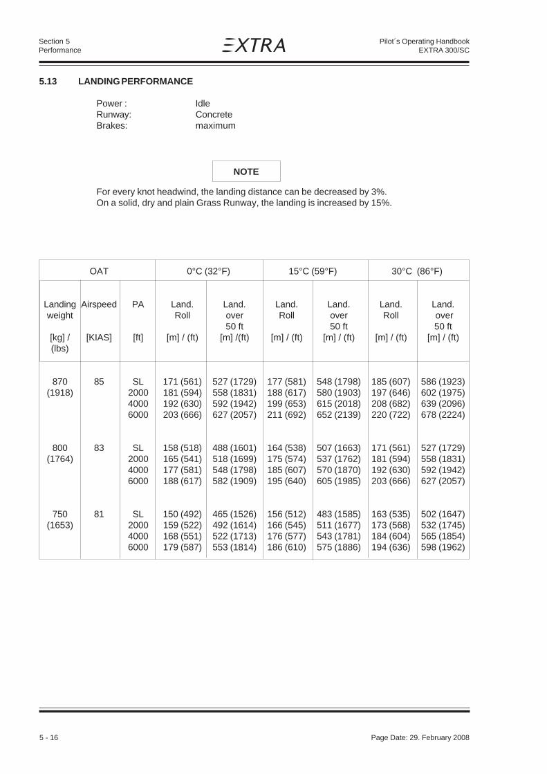
5 - 16 Page Date: 29. February 2008
Pilot´s Operating HandbookEXTRA 300/SC
Section 5Performance
NOTE
5.13 LANDING PERFORMANCE
Power : IdleRunway: ConcreteBrakes: maximum
For every knot headwind, the landing distance can be decreased by 3%.On a solid, dry and plain Grass Runway, the landing is increased by 15%.
OAT 0°C (32°F) 15°C (59°F) 30°C (86°F)
Landing Airspeed PA Land. Land. Land. Land. Land. Land.weight Roll over Roll over Roll over
50 ft 50 ft 50 ft[kg] / [KIAS] [ft] [m] / (ft) [m] /(ft) [m] / (ft) [m] / (ft) [m] / (ft) [m] / (ft)(lbs)
870 85 SL 171 (561) 527 (1729) 177 (581) 548 (1798) 185 (607) 586 (1923)(1918) 2000 181 (594) 558 (1831) 188 (617) 580 (1903) 197 (646) 602 (1975)
4000 192 (630) 592 (1942) 199 (653) 615 (2018) 208 (682) 639 (2096)6000 203 (666) 627 (2057) 211 (692) 652 (2139) 220 (722) 678 (2224)
800 83 SL 158 (518) 488 (1601) 164 (538) 507 (1663) 171 (561) 527 (1729)(1764) 2000 165 (541) 518 (1699) 175 (574) 537 (1762) 181 (594) 558 (1831)
4000 177 (581) 548 (1798) 185 (607) 570 (1870) 192 (630) 592 (1942)6000 188 (617) 582 (1909) 195 (640) 605 (1985) 203 (666) 627 (2057)
750 81 SL 150 (492) 465 (1526) 156 (512) 483 (1585) 163 (535) 502 (1647)(1653) 2000 159 (522) 492 (1614) 166 (545) 511 (1677) 173 (568) 532 (1745)
4000 168 (551) 522 (1713) 176 (577) 543 (1781) 184 (604) 565 (1854)6000 179 (587) 553 (1814) 186 (610) 575 (1886) 194 (636) 598 (1962)

Page Date: 29. February 2008 6 - 1
Section 6Weight and Balance and Equipment List
Pilot´s Operating HandbookEXTRA 300/SC
SECTION 6
WEIGHT AND BALANCE AND EQUIPMENT LIST
Table of Contents
Paragraph PageSECTION 6 WEIGHT AND BALANCE AND EQUIPMENT LIST
6.1 GENERAL............................................................................................................................ 6-3
6.2 AIRCRAFT WEIGHING PROCEDURE ................................................................................. 6-36.2.1 Owners Weight and Balance Record .................................................................................... 6-4
6.3 CENTER OF GRAVITY CALCULATION (SAMPLE PROBLEM) ........................................... 6-56.3.1 Sample ................................................................................................................................ 6-76.3.2 Weight and Balance Record Sheet ...................................................................................... 6-7
6.4 LOADING WEIGHTS AND MOMENTS................................................................................ 6-8
6.5 WEIGHTS AND MOMENT LIMITS .................................................................................... 6-10
6.6 EQUIPMENT LIST .............................................................................................................. 6-11

6 - 2 Page Date: 29. February 2008
Section 6Weight and Balance and Equipment List
Pilot´s Operating HandbookEXTRA 300/SC
Left blank intentionally

Page Date: 29. February 2008 6 - 3
Section 6Weight and Balance and Equipment List
Pilot´s Operating HandbookEXTRA 300/SC
6.1 GENERAL
This section describes the procedure for establishing the basic weight and moment of theaircraft. Sample forms are provided for reference. Procedures for calculating the weight andmovement for various operations are also provided. A comprehensive list of all equipmentavailable for this aircraft is included. It is the responsibility of the pilot to ensure that theaircraft is loaded properly.
6.2 AIRCRAFT WEIGHING PROCEDURE
The aircraft weight is determined by weighing all three wheelloads simultaneously by three scales with the aircraft levelled.(Upper fuselage reference line horizontal)
Datum line for weight arms x is the fire wall.
X1 = distance: fire wall - main wheel
X2 = distance: fire wall - tail wheel
XN = distance: fire wall - item N
XG = distance: fire wall - Center of Gravity
W1 = Sum of weights indicated by the two scales below the main wheels
W2 = Weight indicated by the scale below the tail wheel
W = Total weight = W1 + W2
XG = = C/G positionW
W = W1 + W2 ,
W1
WW2
xG
x2
x1
(W1 x X1) + (W2 x X2)
WXG =
Reference Firewall (plane)
(W1 x X1) + (W2 x X2)

6 - 4 Page Date: 29. February 2008
Section 6Weight and Balance and Equipment List
Pilot´s Operating HandbookEXTRA 300/SC
If a new weight is added to the known old weight and C/G position the resulting new weightand C/G can be obtained by a simple calculation.
Situation before adding item:
Wo, Xo = Airplane weight, C/G positionWn, Xn = Weight, distance from fire wall of item to add
New Weight of airplane and new C/G:
W = Wo + Wn
XG = Wo x Xo + Wn x Xn : C/G positionW
6.2.1 Owners Weight and Balance Record
Enter below all weight change data from aircraft log book.
EXTRA 300/SC SERIAL NUMBER:
Date Description of Weight change Running emptymodification Added (+), Removed (-) weight
Wt./kg Arm/cm Moment/kg*cm Wt./kg Moment/kg*cm[lbs] [inch] [lbs*inch] [lbs] [lbs*inch]
Empty weight ___ ___ _______ incl. unusable fuel
Page Date: 02. July 2012
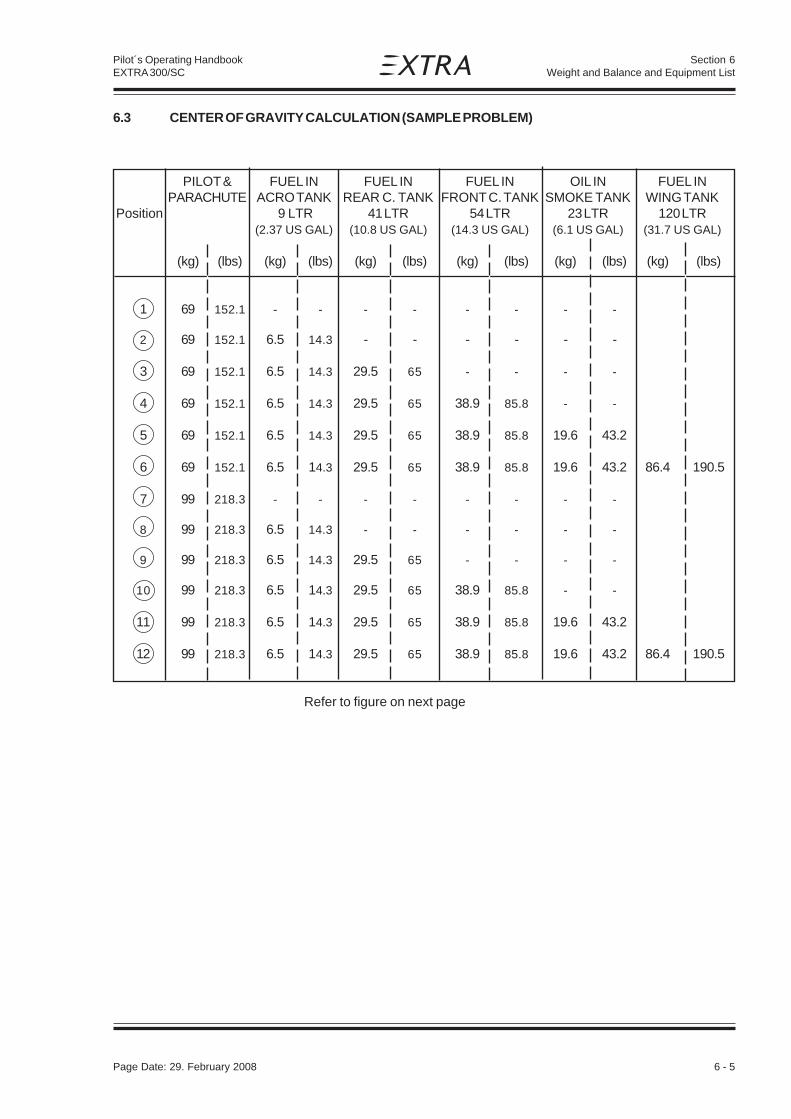
Page Date: 29. February 2008 6 - 5
Section 6Weight and Balance and Equipment List
Pilot´s Operating HandbookEXTRA 300/SC
6.3 CENTER OF GRAVITY CALCULATION (SAMPLE PROBLEM)
PILOT & FUEL IN FUEL IN FUEL IN OIL IN FUEL INPARACHUTE ACRO TANK REAR C. TANK FRONT C. TANK SMOKE TANK WING TANK
Position 9 LTR 41 LTR 54 LTR 23 LTR 120 LTR(2.37 US GAL) (10.8 US GAL) (14.3 US GAL) (6.1 US GAL) (31.7 US GAL)
(kg) (lbs) (kg) (lbs) (kg) (lbs) (kg) (lbs) (kg) (lbs) (kg) (lbs)
1 69 152.1 - - - - - - - -
2 69 152.1 6.5 14.3 - - - - - -
3 69 152.1 6.5 14.3 29.5 65 - - - -
4 69 152.1 6.5 14.3 29.5 65 38.9 85.8 - -
5 69 152.1 6.5 14.3 29.5 65 38.9 85.8 19.6 43.2
6 69 152.1 6.5 14.3 29.5 65 38.9 85.8 19.6 43.2 86.4 190.5
7 99 218.3 - - - - - - - -
8 99 218.3 6.5 14.3 - - - - - -
9 99 218.3 6.5 14.3 29.5 65 - - - -
10 99 218.3 6.5 14.3 29.5 65 38.9 85.8 - -
11 99 218.3 6.5 14.3 29.5 65 38.9 85.8 19.6 43.2
12 99 218.3 6.5 14.3 29.5 65 38.9 85.8 19.6 43.2 86.4 190.5
Refer to figure on next page

6 - 6 Page Date: 29. February 2008
Section 6Weight and Balance and Equipment List
Pilot´s Operating HandbookEXTRA 300/SC
6.3 CENTER OF GRAVITY CALCULATION (SAMPLE PROBLEM)(CONT.)

Page Date: 29. February 2008 6 - 7
Section 6Weight and Balance and Equipment List
Pilot´s Operating HandbookEXTRA 300/SC
6.3.1 Sample
Refer to Center of Gravity Calculation Figure in § 6.3:
Weights MomentsTake-off Condition:Aircraft Empty Weight
(without any fuel) 590.0 kg (1300.7 lbs) 24190 kg cm (20996 in lbs) (7) Pilot & Parachute 99.0 kg (218.3 lbs) 18810 kg cm (16326 in lbs) (8) Fuel in Acro Tank (9 L) 6.5 kg (14.3 lbs) 167 kg cm (145 in lbs) (9) Fuel in Rear Center Tank (41 L) 29.5 kg (65.0 lbs) 2022 kg cm (1755 in lbs)(10) Fuel In Front Center Tank (54 L) 38.9 kg (85.8 lbs) 921 kg cm (799 in lbs)(11) Oil in Smoke Tank (Section 902) 19.6 kg (43.2 lbs) 1303 kg cm (1131 in lbs)(12) Fuel in Wing Tank (120L) 86.4 kg (190.5 lbs) 2851 kg cm (2475 in lbs)===================================================================
869.9 kg (1917.8 lbs) 50264 kgcm (43627 in lbs)
To find C/G follow line "Pilot & Parachute 99 KG" from Empty Weight to Point 7.Now follow line via points 8 thru 11 to point 12.
Refer to Weight and Moment Limits Figure in § 6.5 to find:Weight 869.9 kg (1917.8lbs) Moment 50264 kg cm (43627 in lbs)C/G ~ 57.8 cm (22.8 in)
6.3.2 Weight and Balance Record Sheet
WEIGHT ARM MOMENT
EMPTY WEIGHT
PILOT (arm with respect to seat position)
FUEL ACRO TANK 25,8 cm (10,2")
FUEL REAR CENTER TANK 68,5 cm (27,0")
FUEL FRONT CENTER TANK 23,7 cm (9,3")
OIL SMOKE TANK (See Section 902) 66,5 cm (26,2")
FUEL WING TANK 33 cm (13,0")
Σ Σ Σ Σ Σ W = ΣΣΣΣΣ ( W x X ) =
XG = =ΣΣΣΣΣ ( W x X )
ΣΣΣΣΣ W

6 - 8 Page Date: 29. February 2008
Section 6Weight and Balance and Equipment List
Pilot´s Operating HandbookEXTRA 300/SC
6.4 LOADING WEIGHTS AND MOMENTS
WEIGHT PILOT PILOT
Pilot REAR SEAT POSITION FRONT SEAT POSITION& Parachute ARM = 190 cm (75") ARM = 170 cm (67 ")
KG LBS MOMENT KG x CM (INCH x LBS)
70 154 13300 (11546) 11900 (10331)
75 165 14250 (12370) 12750 (11068)
80 176 15200 (13195) 13600 (11806)
85 187 16150 (14020) 14450 (12544)
90 198 17100 (14845) 15300 (13282)
95 209 18050 (15675) 16150 (14003)
100 220 19000 (16500) 17000 (14740)
FUEL
ACRO TANK
Arm = 25,8 cm (10,2")
LITER (US GAL) KG (LBS) KG x CM (IN LBS)
9 2,4 6,5 14,3 167 145
REAR CENTER TANK
Arm = 68,5 cm (27,0")
LITER (US GAL) KG (LBS) KG x CM (IN LBS)
5 1,3 3,6 7,9 247 21410 2,6 7,2 15,9 493 42815 4,0 10,8 23,8 740 64220 5,3 14,4 31,8 986 85625 6,6 18,0 39,7 1233 107030 7,9 21,6 47,6 1480 128435 9,2 25,2 55,6 1726 149940 10,6 28,8 63,5 1973 171341 10,8 29,5 65,1 2022 1755

Page Date: 29. February 2008 6 - 9
Section 6Weight and Balance and Equipment List
Pilot´s Operating HandbookEXTRA 300/SC
FRONT CENTER TANK
Arm = 23,7 cm (9,3")
LITER (US GAL) KG (LBS) KG x CM (IN LBS)
5 1,3 3,6 7,9 85 7410 2,6 7,2 15,9 171 14815 4,0 10,8 23,8 256 22220 5,3 14,4 31,8 341 29625 6,6 18,0 39,7 427 37030 7,9 21,6 47,6 512 44435 9,2 25,2 55,6 597 51840 10,6 28,8 63,5 683 59345 11,9 32,4 71,4 768 66750 13,2 36,0 79,4 853 74154 14,3 38,9 85,7 921 800
WING TANK
Arm = 33 cm (13,0")
LITER (US GAL) KG (LBS) KG x CM (IN LBS)
5 1,3 3,6 7,9 119 10310 2,6 7,2 15,9 238 20615 4,0 10,8 23,8 356 30920 5,3 14,4 31,8 475 41325 6,6 18,0 39,7 594 51630 7,9 21,6 47,6 713 61935 9,2 25,2 55,6 832 72240 10,6 28,8 63,5 950 82545 11,9 32,4 71,4 1069 92850 13,2 36,0 79,4 1188 103155 14,5 39,6 87,3 1307 113460 15,8 43,2 95,3 1426 123865 17,2 46,8 103,2 1544 134170 18,5 50,4 111,1 1663 144475 19,8 54,0 119,1 1782 154780 21,1 57,6 127,0 1901 165085 22,4 61,2 134,9 2020 175390 23,8 64,8 142,9 2138 185695 25,1 68,4 150,8 2257 1959
100 26,4 72,0 158,8 2376 2063105 27,7 75,6 166,7 2495 2166110 29,0 79,2 174,6 2614 2269115 30,4 82,8 182,6 2732 2372120 31,7 86,4 190,5 2851 2475

6 - 10 Page Date: 29. February 2008
Section 6Weight and Balance and Equipment List
Pilot´s Operating HandbookEXTRA 300/SC
6.5 WEIGHTS AND MOMENT LIMITS
EXAMPLE: At 869.9 kg (1917.8 lbs) and 50264 kgcm (43627 in lbs)CG Location is 57.8 cm (22.8 in) aft of Reference Datum.
CENTER OF GRAVITY - CM (INCH) AFT OF REF DATUM

Page Date: 29. February 2008 6 - 11
Section 6Weight and Balance and Equipment List
Pilot´s Operating HandbookEXTRA 300/SC
6.6 EQUIPMENT LISTEXTRA 300/SC S/N:
Qty. Item Manufacturer Part Nr. Weight Arm ROA* Inst(kg) (m)
1 Engine, AEIO-580-B1A; Lycoming 191.8 -0.72including vacuum pump drive at pad #1ENPL-RT10568 31429 Ror RENPL-RT10568 34097 Aor HENPL-RT10568 34098 A
1 Engine, AEIO-580-B1A; Lycoming 191.8 -0.72ENPL-RT10427 32712 Aor RENPL-RT10427 34099 Aor HENPL-RT10427 34100 Awith
4 long studs 340591 drive spline 327591 washer 32758
1 Inverted oil pickup; VAC-2/6 B&C 32425 0.31 -0.22 R(at engine vacuum pump pad #1)
1 Propeller, MTV-9-B-C/C198-25 (3-blade) MT-Propeller 32285 30.5 -1.15 R1 Spinner, P-810-2 MT-Propeller 31415 0.8 -1.20 R
1 Propeller, MTV-14-B-C/C190-130 (4-blade) MT-Propeller 33970 30.6 -1.15 A1 Spinner, P-967 MT-Propeller 31560 0.8 -1.20 A
1 Governor P-880-5 (2700RPM) MT-Propeller 31509 1.10 -0.91 R
1 Governor P-880-41 (2600RPM) MT-Propeller 32941 1.10 -0.91 A
1 Governor A-210 988 (2700RPM) Woodward 01209 1.10 -0.91 A
1 Exhaust System "6 in 1" (incl. Silencer) Gomolzig 33891 8.48 -0.390 REA300-606000 with
1 2" inlet/outlet cooling shroud Gomolzig 32153EA300-606009
1 Exhaust System "6 in 1" Sky Dynamics 32347 7.42 -0.390 AExtra300 6/1 (w/o Silencer)
1 Exhaust System "6 in 2" Chabord 33792 5.93 -0.390 AExtra330-12-02B (w/o Silencer)
1 Ammeter (+/-30A) VDO 32406 0.080 1.260 R
1 Ammeter (+/-20A) Datcon 33413 0.134 1.260 A
1 Alternator SD-8 (14V; 8 Amps) B&C 31726 1.32 -0.15 R
1 Battery RG-25XC (24 Ah) Concorde 03617 10.52 0.175 R
1 Battery RG-12LSA (11 Ah) Concorde 33697 5.90 0.175 A
1 RPM Indicator, digital P1000 (2600RPM) Horizon 33624 0.68 1.260 R(P100-230-635-00)
1 RPM Indicator, digital P1000 (2700RPM) Horizon 02489 0.68 1.260 A(P100-230-643-00)
1 Oil Press. / Oil Temp. Ind. (2DA3-3KV, 2 1/4") Westach FI3002 0.09 1.260 R1 Oil Temp. Probe (W399-S9) Westach 0.08 -0.11 R1 Oil Press. Sender (387-100MM or 387-100KV) Mediamate 0.12 0.04 R
1 Oil Press. / Oil Temp. Indicator (2 1/4") UMA 33428 0.09 1.260 A(D2-OP130U-OT300U-01)
1 Oil Temp. Probe (1B3A) UMA 0.08 -0.11 A1 Oil Press. Sender (N1EU150G(-A) or UMA 0.12 0.04 A
T1EU150G(-A))
1 CHT/EGT Indicator (EF300/SC-2DA1, 2 1/4") Westach 32570 0.07 1.260 O1 EGT Probe (712-2 DWK) Westach 0.06 -0.37 O1 CHT Probe (712-7 DK) Westach 0.05 -0.20 O
*) R = required, O = optional, A = alternative
Page Date: 02. July 2012

6 - 12 Page Date: 29. February 2008
Section 6Weight and Balance and Equipment List
Pilot´s Operating HandbookEXTRA 300/SC
*) R = required, O = optional, A = alternative
1 CHT/EGT Indicator (2 1/4") UMA 33438 0.07 1.260 A(D2-ET1K7K-CT600J-01)
1 EGT Probe (2BU20) UMA 0.06 -0.37 A1 CHT Probe (2B18 or 2B02) UMA 0.05 -0.20 A
1 Engine Data Management System (EGT-701) JPI 93102.029-PG 2.25 0.106 O6 EGT Probe (M-111) JPI O6 CHT Probe (M-113, spark plug gasket) JPI O1 OAT Probe (400510) JPI O1 Oil Temp. Probe (400500-L) JPI O1 Manifold Press. Probe (604010) JPI O1 RPM Probe (420815-1) JPI O1 Fuel Flow Transducer (201-B or FXT-201) Flowscan O1 Fuel Flow Transducer (680501 or 680600) Shadin A
1 Manifold Pressure / Fuel Flow Ind. United Instr. 33448 0.540 1.260 R(UI6331-H.217)
1 Manifold Pressure / Fuel Flow Ind. United Instr. 03247 0.540 1.260 A(UI6331-H.186)
1 Fuel Qty Ind. Front Center Tank VDO 00390 0.120 1.260 R
1 Fuel Qty Ind. Front Center Tank Datcon 33411 0.145 1.260 A
1 Fuel Qty Ind. Rear Center Tank VDO 00390 0.120 1.260 R
1 Fuel Qty Ind. Rear Center Tank Datcon 33411 0.145 1.260 A
1 Fuel Qty. Ind. Wing Tank VDO 200171 0.120 1.260 R
1 Fuel Qty. Ind. Wing Tank Datcon 33412 0.145 1.260 A
1 Fuel Qty Probe Front Center Tank VDO 32610 0.184 0.220 R
1 Fuel Qty Probe Front Center Tank Datcon 33410 0.212 0.220 A
1 Fuel Qty Probe Rear Center Tank VDO 32611 0.184 0.700 R
1 Fuel Qty Probe Rear Center Tank Datcon 33409 0.212 0.700 A
1 Fuel Qty Probe Wing Tank VDO FM4006 0.120 0.280 R
1 Accelerometer (2 1/4") Falcon 01206 0.294 1.270 R
1 Digital Accelerometer (2 1/4", TL-3424_EXT) TL 32582 0.520 1.265 A
1 Magnetic Compass (C2300) Airpath 00189 0.260 1.290 R
1 Magnetic Compass (PG2A) SIRS Navigation Ltd 33085 0.132 1.290 A
1 Air Speed Indicator (UI8030 B.882) United Instr. 32811 0.322 1.290 R
1 Air Speed Indicator (UI8030 B.896, dual scale) United Instr. 33630 0.322 1.290 A
1 Air Speed Indicator (6531-559, metric) Winter 32812 0.205 1.290 A
1 Airspeed Indicator (LUN1106.K2B4/SC) Mikrotechna Praha 34155 0.500 1.280 A
1 Airspeed Indicator (LUN1106.P2B4/SC, metric) Mikrotechna Praha 34156 0.500 1.280 A
1 Altimeter (UI5934PD-3 A.134) United Instr. 30416 0.610 1.280 R
1 Altimeter (UI5934PD-3M A.665) United Instr. 33652 0.610 1.280 R
1 Altimeter (4FGH10, metric) Winter 31393 0.330 1.280 A
1 Altimeter (LUN1128.10B6) Mikrotechna Praha 34159 0.590 1.280 A
1 Vertical Speed Indicator (UI7030 C.27) United Instr. 01485 0.350 1.280 O
1 Vertical Speed Ind. (UI7030-M C.194, metric) United Instr. 33653 0.350 1.280 A
1 Vertical Speed Ind. (LUN1144.B0B1) Mikrotechna Praha 34161 0.400 1.280 A
1 Vertical Speed Ind. (LUN1144.F0B1, metric) Mikrotechna Praha 34162 0.400 1.280 A
1 Horizon, electric digital RCA 2600-2 RC Allen 33027 0.241 1.225 O
Qty. Item Manufacturer Part Nr. Weight Arm ROA* Inst(kg) (m)
Page Date: 5. September 2013

Page Date: 29. February 2008 6 - 13
Section 6Weight and Balance and Equipment List
Pilot´s Operating HandbookEXTRA 300/SC
1 Horizon, electric digital RCA 2600-2 RC Allen 33881 0.128 1.290 A(102-0202-01)
1 Horizon, electric digital RCA 2600-3 RC Allen 33217 0.454 1.217 O
1 Horizon, electric digital RCA 2600-3 RC Allen 33882 0.180 1.290 A(102-0203-01)
1 Slip indicator for RCA 2600 (444-0010-01) RC Allen 33529 0.030 1.310 O
1 Flighthour Counter Winter 01605 0.150 1.260 O
1 Digital Clock Astrotech FI0004 0.113 1.260 O
2 Main Wheel Tires Misc. 02323 2.447 0.110 R
1/1 Wheel fairing (CFK) Extra 53102.301-LV-L/R 1.500 0.160 O
1 Bottom fuselage cover (Belly fairing) Extra 2C203.021-VF 5.20 0.562 R
1 Bottom fuselage cover with window Extra 8C416.020-VF 5.85 0.562 A
1 Instrument Panel Extra 7C102.001 0.400 1.300 R
1 Instrument Panel, alternative (Aluminum) Extra 8C503.____ 0.470 1.300 A
1 Instrument Panel, alternative (Carbon) Extra 8C506.____ 0.300 1.300 A
1 12V Power Socket Sutars 31494 0.028 1.290 O
1 VHF-COM (AR 4201) Becker 00652 0.670 1.200 R
1 VHF-COM (AR 6201, 8.33kHz ch. spacing) Becker 33041 0.850 1.200 A
1 VHF-COM (ATR 833, 8.33kHz ch. spacing) Funkwerk 32363 0.600 1.200 A
1 Transponder (Mode A/C) ATC4401 Becker 31002 0.730 1.200 O
1 Transponder (Mode S) BXP6401-2-(01) Becker 31860 0.780 1.200 A
1 Transponder TRT800H f.u.n.k.e. 32090 0.600 1.200 A
1 Slip and Skid ind. (Libelle) Rieker FI0009 0.050 1.310 O
1 ELT 3000 System 3000-10/-11 Pointer 50025/02154 0.990 1.383 O
1 ME406 ELT 406MHz System Artex 32173-PG 1.205 1.360 Oincl. Antenna 110-773 (for Artex) Artex 33524 0.08 2.92 O
1 ELT 406 AF COMPACT KANNAD 34210 1.11 1.360 A
1 ELT 406 AF INTEGRA KANNAD 34422 0.99 1.360 A
ELT Antenna AV-200 Rami 33965 0.08 2.92 AO(for Artex or KANNAD)
1 Single Pump Smoke System Extra 8C111.001-VM 4.591 0.605 O
1 External Power Receptical (Piper Type Socket) Cole Hersee 31731 1.300 1.900 O
1/1 Sighting device (45°/90°), Carbon Extra 8C801.030-01/02 0.25 1.260 Oeach
2 Electric Actuator Pedal Adjust. SKF 01996 3.25 1.605 O
1 Safety Belt Assy Hooker FK0002 or FK0019 3.30 1.950 R(seat belts w. single ratchet,shoulder harness and crotch strap)
1 Safety Belt Assy (w. dual ratchets) Hooker 31856 3.70 1.950 A(seat belts w. double ratchets,shoulder harness and crotch strap)
2 Strobe Lights AVEO Engineering 34217 0.055 0.420 O
1 Cabin Heating System Extra Option 300/SC 2.551 0.141 OKBS11
1 Throttle Control Teleflex 33051 0.420 0.050 R
1 Throttle Control Cablecraft 34375 0.570 0.050 A580-540-502
Page Date: 19. May 2014
*) R = required, O = optional, A = alternative
Qty. Item Manufacturer Part Nr. Weight Arm ROA* Inst(kg) (m)

6 - 14 Page Date: 29. February 2008
Section 6Weight and Balance and Equipment List
Pilot´s Operating HandbookEXTRA 300/SC
1 Single Oil cooler rear, 8000353 Aero Classics 31417 1.65 -0.22 R
1 Single Oil cooler rear, 20009A Niagara Thermal Prod. 34674 1.65 -0.22 A
1 Additional Oil Cooler Sys., 8406R Meggitt/Aero Classics 00107 2.00 -0.80 O
1 Additional Oil Cooler Sys., 20002A Niagara Thermal Prod. 34675 2.00 -0.80 A
1 Additional Oil Cooler Sys., 8001602 Aero Classics 34676 2.00 -0.80 A
*) R = required, O = optional, A = alternative
Qty. Item Manufacturer Part Nr. Weight Arm ROA* Inst(kg) (m)
Page Date: 4. March 2016

Page Date: 29. February 2008 7 - 1
Section 7Description and Operation of Aircraft and Systems
Pilot´s Operating HandbookEXTRA 300/SC
SECTION 7
DESCPRIPTION AND OPERATIONOF AIRCRAFT AND SYSTEMS
Table of Contents
Paragraph Page
Page Date: 29. February 2008
SECTION 7 DESCPRIPTION AND OPERATION OF AIRCRAFT AND SYSTEMS
7.1 THE AIRCRAFT .................................................................................................................. 7-3
7.2 FUSELAGE ......................................................................................................................... 7-3
7.3 WINGS ................................................................................................................................ 7-3
7.4 EMPENNAGE ..................................................................................................................... 7-4
7.5 FLIGHT CONTROL SYSTEM ............................................................................................. 7-47.5.1 Primary Control System....................................................................................................... 7-47.5.2 Longitudinal Flight Control System ...................................................................................... 7-47.5.3 Lateral Flight Control System .............................................................................................. 7-47.5.4 Directional Flight Control System ........................................................................................ 7-47.5.5 Secondary Control ............................................................................................................... 7-4
7.6 INSTRUMENT PANEL ........................................................................................................ 7-6
7.7 LANDING GEAR ................................................................................................................. 7-7
7.8 SEATS, SEAT BELTS ......................................................................................................... 7-8
7.9 CANOPY ............................................................................................................................. 7-8
7.10 POWER PLANT .................................................................................................................. 7-87.10.1 Engine ................................................................................................................................. 7-87.10.2 Oil System ........................................................................................................................... 7-97.10.3 Engine Installation ............................................................................................................... 7-97.10.4 Propeller .............................................................................................................................. 7-97.10.5 Throttle ................................................................................................................................ 7-97.10.6 Mixture .............................................................................................................................. 7-107.10.7 RPM-Control ..................................................................................................................... 7-107.10.8 Fuel Selector Valve ............................................................................................................ 7-107.10.9 Exhaust System ................................................................................................................ 7-10
7.11 FUEL SYSTEM ................................................................................................................. 7-10
7.12 ELECTRICAL SYSTEM .................................................................................................... 7-13
7.13 CABIN ENVIRONMENT CONTROL ................................................................................. 7-13

7 - 2 Page Date: 29. February 2008
Section 7Description and Operation of Aircraft and Systems
Pilot´s Operating HandbookEXTRA 300/SC
Left blank intentionally

Page Date: 29. February 2008 7 - 3
Section 7Description and Operation of Aircraft and Systems
Pilot´s Operating HandbookEXTRA 300/SC
SECTION 7
DESCPRIPTION AND OPERATIONOF AIRCRAFT AND SYSTEMS
7.1 THE AIRCRAFT
The aircraft EXTRA 300/SC is designed and developed by EXTRA Flugzeugproduktions-und Vertriebs- GmbH, Dinslaken 46569 Hünxe, Federal Republic of Germany, inaccordance with the Joint Aviation Authorities FAR-23 acrobatic category to fullfill theprimary flight training, and acrobatic training up to the unlimited acrobatic level.
EXTRA 300/SC is a light weight, robust, single piston-engined, one-seat aircraft with afuselage structure in tig-welded steel-tube construction.The landing gear, wing, and tail are made of epoxy, reinforced with glass- and carbonfiber.The items are qualified up to 72°C.The aircraft is designed to operate within a range of ambient air temperature from -20°C to+38°C (-4°F => 100°F) at sea level. It is possible to start the engine using the aircraft batteryat -20°C (-4°F) without preheating.
7.2 FUSELAGE
The fuselage structure consists of a steel tube construction integrating the wing andempennage connections as well as the seat. The lower part of the fuselage and the sidesbelow the wing are covered with a carbon belly fairing. Within the exhaust area aluminumsheet metal is used. The rear part of the fuselage is covered with Ceconite® 102.The upper fuselage body surface is one part from firewall to vertical stabilizer including thecorrelated frame for the canopy. It consists of a carbon sandwich laminate.The canopy itself is a single part. The canopy frame is a carbon laminate construction.For additional pilot protection a roll bar is installed behind the pilot's seat.
7.3 WINGS
The wing is a CRP construction. The dual chamber main spar - being a fail safe design -consists of carbon roving caps combined with CRP webs. Core foam is a PVC foam. Thewing shell is built by a Honeycomb sandwich with CRP laminates. Wing box ribs are madeof carbon fiber composite with honeycomb core. The ribs in the nose section are made ofwood. The connection to the fuselage is arranged by two bolts piercing through the sparparallel to the centerline of the fuselage and two brackets at the rear spars.The ailerons are supported at four points in spherical bearings. In addition the aileron tip hasa shielded horn balance.To reduce pilot's hand forces the hinge line of the ailerons is positioned 25% of the aileronchord. Furthermore the ailerons are equipped with "spades" to decrease pilot's forces. Theaileron control push-pull rods are connected to the aileron at the second bearing point (inspan-wise direction). To prevent flutter the ailerons are mass balanced at the leading edgeof the shielded horn.

7 - 4 Page Date: 29. February 2008
Section 7Description and Operation of Aircraft and Systems
Pilot´s Operating HandbookEXTRA 300/SC
7.4 EMPENNAGE
The EXTRA 300/SC possesses a cruziform empennage with stabilizers and moveablecontrol surfaces. The spars consist of PVC foam cores, CRP caps and webs. The shell isbuilt by honeycomb sandwich with CRP laminates. The control surfaces are are mounted inspherical bearings and balanced aerodynamically with unshielded horns at the tip. Toprevent flutter rudder and elevator are mass balanced. The balance weights are installed inthe leading edges of the unshielded horn´s.The R/H elevator side incorporates a trim tab supported at two piano type hinges.
7.5 FLIGHT CONTROL SYSTEM
7.5.1 PRIMARY CONTROL SYSTEM
The EXTRA 300/SC is equipped with a conventional control stick and mechanicallyadjustable rudder pedals. The primary control surfaces are operated through a directmechanical linkage.
7.5.2 LONGITUDINAL FLIGHT CONTROL SYSTEM
The control stick bearing is housed in a torque tube, which is also linked to the lateral flightcontrols. The stick movements are transferred to the elevator by carbon push-pull rods.
7.5.3 LATERAL FLIGHT CONTROL SYSTEM
Aluminium and carbon push-pull rods connect the torque tube to the ailerons. Theconnections feature sealed rod ends. The ailerons are statically as well as dynamicallybalanced. (Dynamically with spades).The ailerons are supported by lubricated, sealed bearings.
7.5.4 DIRECTIONAL FLIGHT CONTROL SYSTEM
The rudder pedals with brake pedals are mechanically adjustable and operate the rudderthrough a control cable system. Springs keep the cables under tension when the pedals arenot operated.
7.5.5 SECONDARY CONTROL
The elevator trim uses a trim servo connected to the trim tab by a double Bowden cable.The trim switch is either located on the control stick or together with the trim positionindicator on the right upper side of the instrument panel. The double cable actuation of thetrim tab is a fail safe design to prevent flutter in case of a single control joint failure.The canopy is operated from the inside and outside by the interior locking handles. Thesehandles are used for locking as well as for normal and emergency operation.The starter/magneto switch is located on the left side of the instrument panel.
Page Date: 12. February 2010

Page Date: 29. February 2008 7 - 5
Section 7Description and Operation of Aircraft and Systems
Pilot´s Operating HandbookEXTRA 300/SC
Left blank intentionally

7 - 6 Page Date: 29. February 2008
Section 7Description and Operation of Aircraft and Systems
Pilot´s Operating HandbookEXTRA 300/SC
7.6 INSTRUMENT PANEL
Refer to the following figures and the related lists for the instruments, switches, lamps andcircuit breakers installed in the EXTRA 300/SC.
Figure 7-1: Instrument panel (some optional equipment is shown as well)
Figure 7-2: Switches, circuit breakers, light
Page Date: 5. September 2013
1 2 3 4 5 6 7 8 9 10 11 12 13 14
ON ON ARM
MASTER SWITCH
BOOST PUMP SYSTEM
SMOKEOUTPUT
ALT SMOKE SYS STARTER COM TRIMXPDR
135101510
10 OFF
5
12 V
32 WARNING OFF OFF REFILL
ON
5
STROBE LIGHTS
OFF

Page Date: 29. February 2008 7 - 7
Section 7Description and Operation of Aircraft and Systems
Pilot´s Operating HandbookEXTRA 300/SC
Position Item1 12 Volt power source jack*2 COM3 Air speed indicator4 Blank5 Manifold pressure / fuel flow6 Magn. direction indicator7 RPM indicator8 Accelerometer*9 Trim position indicator10 Trim position switch (on panel or control stick)11 Altimeter12 XPDR13 ELT*14 Ammeter15 Oil pressure / oil temperature16 Fuel quantity Rear center tank17 Fuel quantity Front center tank18 Fuel quantity Wing tanks19 EGT / CHT indicator*20 Magneto selector switch & starter21 Switches, circuit breakers, light as listed below:
Switches, Circuit Breakers, Light (Figure 7-2)
Position Item1 Alternator warning light incl. press-to-test feature2 Master switch3 Boost pump switch circuit breaker4 Strobe lights switch circuit breaker*5 Smoke system switch*6 Overvoltage protection circuit breaker7 Alternator output circuit breaker8 Smoke system circuit breaker*9 Starter circuit breaker10 Instruments circuit breaker11 COM circuit breaker12 XPDR circuit breaker13 TRIM circuit breaker14 12 V circuit breaker*
* Optional equipment
NOTE
These lists may be modified by the minimum equipment requirements of individualcertifying authorities!
7.7 LANDING GEAR
The EXTRA 300/SC is designed as a conventional tail-wheel airplane. The main gear is acomposite construction with a multichamber spring made of glass fiber webs and caps. Themain wheels have a size of 5.00-5 and they are equipped with hydraulic disc brakes. The tailwheel has a solid rubber tire with full-swivel capability.
Page Date: 5. September 2013

7 - 8 Page Date: 29. February 2008
Section 7Description and Operation of Aircraft and Systems
Pilot´s Operating HandbookEXTRA 300/SC
7.8 SEATS, SEAT BELTS
The seat is a shaped carbon composite construction. It´s back rest position and angle ismechanically adjustable on ground by quickpins and bolts. The lower seat surface itself isfixed.The seat belt assembly consists of right and left shoulder straps, two right and two left lapbelts and a negative g-strap. All belts are adjustable. The lap belts have a separate singlepoint release for redundant safety during acrobatic maneuvers. If one release is openedunintentionally the second one guarantees full safety. To assure safe operation one releasemust be closed to the right and the other one to the left. For acrobatic maneuvers the seatbelt system should be tightened firmly.
7.9 CANOPY
The canopy is manufactured in one section and can be manually operated by interior lockinghandles located on the left side on the canopy.To open the canopy from inside proceed as follows: Pull together the interior locking handlesand lift canopy to the right. The canopy strap will limit the opening angle.To lock the canopy pull together the interior locking handles and then release.To open the canopy from the outside use the interior handles by reaching through the smallwindow (bad weather window) and proceed as mentioned above.Generally the emergency operation is equal to the normal procedure. When opening thecanopy in normal flight the low pressure over the canopy will flip the canopy fully openimmediately. However complete jettison of the canopy is possible. In this case the canopycan be finally unlatched at its RH hinge line by the following action: push canopy slightlyforward while opening.
7.10 POWER PLANT
7.10.1 ENGINE
The power plant consists of one Textron-Lycoming six-cylinder, horizontally opposed,aircooled, direct drive, fuel injection engine type with inverted oil system.The rated power at 2700 RPM is 315 HP (234.9 kW).The rated power at 2600 RPM is 303 HP (225.9 kW).The rated power at 2400 RPM is 286 HP (213.3 kW).
Engine specification: Textron - Lycoming AEIO-580-B1A
The AEIO-580-B1A engine is equipped with special antivibration counterweights.The following accessories are included in the power plantinstallation:
-Fuel Injector: Precision-Magnetos: Slick-Alternator: B&C-Starter: Sky-Tec-Fuel pump: Gates Lear-Shielded ignition system-Propeller governor drive-Transistor voltage regulator

Page Date: 29. February 2008 7 - 9
Section 7Description and Operation of Aircraft and Systems
Pilot´s Operating HandbookEXTRA 300/SC
The engine is operated with the following manual controls:
-Throttle control-RPM control-Fuel mixture control
The propeller governor monitors the RPM automatically and prevents overspeeding. In theevent that oil pressure is lost the propeller is automatically adjusted to coarse pitch in orderto avoid overspeeding.
100/130 aviation grade fuel (AVGAS 100/100LL) is the minimum grade recommended bythe manufacturer of the engine.100/130 aviation fuel is also the maximum grade.
7.10.2 OIL SYSTEM
The engine oil is cooled using a Single Oil Cooler. The oil cooler is mounted on the aft, righthand side of the engine. The oil level is determined by a dip-stick which is accessiblethrough an opening in the upper cowling.
Oil capacity:
Max. sump capacity: 16 qts.Min. sump capacity: 9 qts.
NOTE
With the engine in good condition the minimum engine oil capacity is safe for maximumendurance in the aerobatic category.
For temperatures and oil grades refer to Section 1.7.
7.10.3 ENGINE INSTALLATION
The engine is mounted with four shock-mounts to the tig-welded steel tube engine support,which is attached to the fuselage with four bolts on the firewall plane.
The engine cowling is divided into two parts, a lower and an upper part both made of carbonfibre reinforced epoxy. The parts are fixed by a number of screws and the upper cowling hasa separate hatch for easy access to the oil dip-stick.
7.10.4 PROPELLER
The propeller is a 3-blade wood composite, constant speed propeller type MTV-9-B-C/C198-25 with a diameter of 1,98 m.
7.10.5 THROTTLE
Control lever (cub-type) mounted on the left side of the cockpit.

7 - 10 Page Date: 29. February 2008
Section 7Description and Operation of Aircraft and Systems
Pilot´s Operating HandbookEXTRA 300/SC
7.10.6 MIXTURE
Vernier control located at the right side of the cockpit (red knob).
7.10.7 RPM-CONTROL
Vernier control located at left side of the cockpit (blue knob).Preselection of RPM possible due to constant speed governor.
7.10.8 FUEL SELECTOR VALVE
A rotary fuel selector valve is mounted behind the firewall on the right side of the fuselage. Atorque tube connects the valve to the cockpit handle. Pull and turn the handle 90° to openthe valve to the Acro & Center tanks. A further 90° turn switches to the wing tank fuel supply.
Position down = CLOSEDPosition left = ACRO & CENTER TANKSPosition up = WING TANK
7.10.9 EXHAUST SYSTEM
The EXTRA 300/SC is equipped with a Gomolzig 6 in 1 exhaust system with integratedsilencer.As an option the EXTRA 300/SC can be equipped with a complete 6 in 1 exhaust systemmanufactured by Sky Dynamics Corporation. The system is made from stainless steel anhas no silencer. If it is installed, the aircraft can receive an airworthyness certificate only inthe Acrobatic Category.
7.11 FUEL SYSTEM
The fuel system consists of two separate, independent tank systems (refer to Figure 7-3).
- Acro & Center tanks system- Wing tank system
Acro & Center tanks system:An acro tank of 9 liters (2.37 US Gal.) is mounted in the fuselage just behind the firewall.The front center tank is mounted above having a capacity of 54 liters (14.3 US Gal.). Behindthe main spar of the wing the rear center tank is installed containing 41 liters (10.8 US Gal.).The acro tank is connected to the center tanks in a gravity feed system. To prevent anycrossflow between the center fuel tanks, check valves are placed in the respective supplylines upstream the interconnection to the acro fuel tank.Each center tank has a 2" diameter filler cap for gravity refueling on the top of the forwardfuselage. The caps are labelled "FUEL AVGAS 100/100LL". Usable fuel in acro & bothcenter tanks is 101 liters (26.7 US Gal.).Although the center tanks can be filled seperately they can only be used in combination byselecting the ACRO & CENTER TANKS position of the fuel selector. However the pilot canaffect the center of gravity position of the aircraft by filling the tanks unequally. In each case,even when one center tank is empty, the fuel supply to the engine is safe.

Page Date: 29. February 2008 7 - 11
Section 7Description and Operation of Aircraft and Systems
Pilot´s Operating HandbookEXTRA 300/SC
Figure 7-3: Fuel system
Page Date: 12. February 2010
7 - 12 Page Date: 29. February 2008
Section 7Description and Operation of Aircraft and Systems
Pilot´s Operating HandbookEXTRA 300/SC
NOTES
When ACRO & CENTER TANKS are selected in flight the tank with the higher fuellevel will empty slightly faster than the other.
When both front and rear center tank indications read "ZERO" the remaining fuel inthe acro tank is less than 9 liters (2.37 US Gal.). 2.5 liters (0.66 US Gal.) of thisremaining fuel are not usable.
The center tanks are made from aluminum and are covered by a separate shell made ofGRP for safety. The space between the aluminum tank and the safety GRP shell is ventedand drained overboard. In case of a crack in the aluminium tank, the leaking fuel is dumpedoverboard, while the GRP shell will indicate the location of the leak by coloring blue.
Wing tank system:The root section of each wing in front of main spars forms an integral fuel tank providing twointerconnected tanks with 120 liters (31,7 US GAL.) total capacity. Each side of the wing hasa 2" diameter filler cap for gravity refueling. The caps are labelled "FUEL AVGAS 100/100LL".The wing tank can be completely emptied in flight .
NOTE
The wing tank must be empty when flying aerobatic maneuvers.
Adequate venting is provided in each tank by ventilation-tubes.All ventilation and drain lines merge at the right side of the fuselage and end on the uppermain gear leg.In addition to the engine driven fuel pump an electrically driven auxiliary fuel pump (boostpump) with by-pass and having sufficient capacity to feed the engine at take-off power isfitted as a safety device against failure of the engine-driven pump. The boost pump switch islocated on the instrument panel.A fuel filter with drain is installed between the fuel selector valve and the boost pump.Separate drains are located at the lowest point of each tank system: the acro & center tanksdrain on the right underside and the wing tank drain on the left underside of the fuselage justbehind the main gear attachment.Normal float type transducers and electrically operated fuel indicators are used.Alternatively, variable capacitance type transducers for the center tanks are used.
Page Date: 10. January 2011

Page Date: 29. February 2008 7 - 13
Section 7Description and Operation of Aircraft and Systems
Pilot´s Operating HandbookEXTRA 300/SC
7.12 ELECTRICAL SYSTEM
The electrical power generation system (refer to fig. 7-4) consists of a 12 V alternator withrectifier and transistor voltage regulator. The alternator is mounted on and driven by theengine.The field current is controlled by the voltage regulator to give a nominal output of 13,8 Vunder all load conditions.Circuit protection against over-voltage is provided by the voltage regulator. If an over-voltageoccurs the regulator causes the 2 amp. OV PROTECT circuit breaker to trip. In this case arelais disconnects the alternator from the aircraft system. This is indicated by the litalternator warning light. Consider that in flight in this case the battery is the only powersource.The maximum load taken from the alternator is 8.4 Amps (@2700 RPM).A 12 V leak proof battery is connected across the alternator output to stabilize the supplyand to maintain all essential services in the event of an alternator failure and when theengine is not operating. The battery is mounted behind the firewall.The master-switch is located on the instrument panel.The system is equipped with an ampere meter, which allows monitoring the battery state ofcharge.All electrical circuits are protected by circuit breakers or fuses. All circuit breakers arelocated on the instrument panel and are easily accessible to the pilot during flight.The electrical system is adequately suppressed to ensure satisfactory operation of the radioequipment.All wires, switches, circuit breakers etc. are manufactured to related aeronauticalspecifications.
7.13 CABIN ENVIRONMENT CONTROL
A ventilation system in the canopy is provided for the supply of fresh air to the cabin. Thebad weather window is equipped with a ventilation scoop to provide supply of fresh air to thecabin. Additionally, to the right and left side of the cockpit an eyeball-type adjustable vent isinstalled.
Page Date: 10. January 2011

7 - 14 Page Date: 29. February 2008
Section 7Description and Operation of Aircraft and Systems
Pilot´s Operating HandbookEXTRA 300/SC
Figure 7-4, Sheet 1: Electrical system, power generation
Page Date: 10. January 2011
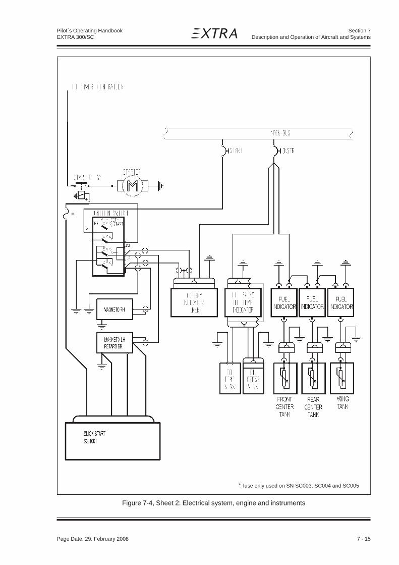
Page Date: 29. February 2008 7 - 15
Section 7Description and Operation of Aircraft and Systems
Pilot´s Operating HandbookEXTRA 300/SC
Figure 7-4, Sheet 2: Electrical system, engine and instruments
*
* fuse only used on SN SC003, SC004 and SC005

7 - 16 Page Date: 29. February 2008
Section 7Description and Operation of Aircraft and Systems
Pilot´s Operating HandbookEXTRA 300/SC
Figure 7-4, Sheet 3: Electrical system, further equipment
Page Date: 5. September 2013

Page Date: 29. February 2008 8 - 1
Section 8Handling, Servicing and Maintenance
Pilot´s Operating HandbookEXTRA 300/SC
SECTION 8
HANDLING, SERVICING AND MAINTENANCE
Table of Contents
Paragraph PageSECTION 8 HANDLING, SERVICING
8.1 INTRODUCTION................................................................................................................. 8-3
8.2 AIRPLANE INSPECTION PERIODS................................................................................... 8-3
8.3 PILOT CONDUCTED PREVENTIVE MAINTENANCE ....................................................... 8-3
8.4 ALTERATIONS OR REPAIR ............................................................................................... 8-3
8.5 SERVICING......................................................................................................................... 8-3
8.6 GROUND HANDLING......................................................................................................... 8-4

8 - 2 Page Date: 29. February 2008
Section 8Handling, Servicing and Maintenance
Pilot´s Operating HandbookEXTRA 300/SC
Left blank intentionally

Page Date: 29. February 2008 8 - 3
Section 8Handling, Servicing and Maintenance
Pilot´s Operating HandbookEXTRA 300/SC
SECTION 8
HANDLING, SERVICING AND MAINTENANCE
8.1 INTRODUCTION
a) The airplane owner should establish contact with the dealer or certified service station forservice and information.
b) All correspondence regarding the airplane must include its serial number which isstamped on a plate on the L/H rear part of the fuselage.
c) A service manual with revision service may be procured from the manufacturer.
8.2 AIRPLANE INSPECTION PERIODS
As required by national operating rules all airplanes must pass a complete annual inspectionevery twelve calendar months. In addition to the annual inspection airplanes must pass acomplete inspection after every 100 flights hours with a minor check after50 and 25 hours.
The Airworthiness Authority may require other inspections by the issuance of airworthinessdirectives applicable to the aircraft, engine, propeller and components. The owner isresponsible for compliance with all applicable airworthiness directives and periodicalinspections.
8.3 PILOT CONDUCTED PREVENTIVE MAINTENANCE
Pilots operating the airplane should refer to the regulations of the country of certification forinformation of preventive maintenance that may be performed by pilots. All othermaintenance required on the airplane is to be accomplished by appropriately licensedpersonnel. Airplane dealer should be contacted for further information
Preventive maintenance should be accomplished with an appropriate service manual.
8.4 ALTERATIONS OR REPAIR
Alterations or repairs of the airplane must be accomplished by licensed personel.
8.5 SERVICING
In addition to the airplane inspection periods (8.2) information for servicing the aircraft withproper oil and fuel is covered in Section 2 (Limitations) and Section 7 (Descriptions andOperation).

8 - 4 Page Date: 29. February 2008
Section 8Handling, Servicing and Maintenance
Pilot´s Operating HandbookEXTRA 300/SC
8.6 GROUND HANDLING
a) Due to its low weight and the free swiveling tail wheel two persons can easily move theairplane by hand.
b) If the aircraft is parked in the open, it must be protected against the effects of weather,the degree of protection depending on severity of the weather conditions and the expectedduration of the parking period. When the airplane is parked in good weather conditions forless than a half day park the aircraft headed into the wind and place wheel chocks at themain wheels.

Section 9Supplements
Page Date: 29. February 2008 9 - 1
Pilot´s Operating HandbookEXTRA 300/SC
SECTION 9
SUPPLEMENTSDoc-No. EA-0C701.1
Table of Contents
Section Pages
9 Supplements ............................................................................................................ 4 p.
901 Steerable Tail Wheel ............................................................................................... 4 p.
902 Smoke System ......................................................................................................... 8 p.
903 BECKER ATC 4401 Transponder ........................................................................... 8 p.
904 BECKER BXP 6401 Transponder ........................................................................... 10 p.
905 Digital RPM Indicator .............................................................................................. 6 p.
906 Accelerometer TL 3424_EXT .................................................................................. 6 p.
907 External Power ........................................................................................................ 4 p.
908 ARTEX ME-406 ELT .................................................................................................. 8 p.
909 Electric Pedal Adjustment ...................................................................................... 4 p.
910 Airplanes registered in Brazil and operating under theAgência Nacional de Aviação Civil requirements ............................................... 4 p.
911 f.u.n.k.e. TRT800H Transponder ............................................................................. 10 p.
912 Cabin Heating System ............................................................................................ 4 p.
913 KANNAD 406 AF COMPACT/INTEGRA ELT ............................................................. 8 p.
SECTION 9 SUPPLEMENTS
9 SUPPLEMENTS .................................................................................................................... 3
Page Date: 19. May 2014

Section 9Supplements
9 - 2 Page Date: 29. February 2008
Pilot´s Operating HandbookEXTRA 300/SC
Left blank intentionally

Section 9Supplements
Page Date: 29. February 2008 9 - 3
Pilot´s Operating HandbookEXTRA 300/SC
9 SUPPLEMENTS
9.1 INTRODUCTION
Section 9 "Supplements" of the Pilot´s Operating Handbook contains all information, neces-sary for a safe and efficient operation of the airplane when equipped with one or more of thevarious optional systems and equipment not provided with the standard airplane.
9.2 NOTES
The described systems and equipment are certified by the EASA for the EXTRA 300/SC.Pages and contents of this section may not be exchanged and alterations of or additions tothe approved contents may not be made without the EXTRA Flugzeugproduktions- undVertriebs- GmbH/EASA approval. The editor has the copyright of these Supplements and isresponsible for edition of revisions. The log of effective pages is found under section 0.4 ofthis Pilot's Operating Handbook.
Each Supplement section (e.g. steerable tailwheel) covers only a single system, device, orpiece of equipment and is a self-contained, miniature Pilot´s Operating Handbook. The owneris responsible for incorporating prescribed amendments and should make notes about theseon the records of amendments. It is responsibility of the pilot to be familiar with the contentsof relevant supplements.
POH Supplements must be in the airplane for flight operations when the subject equipment isinstalled or special operations are to be performed.
The Table of Contents shows all EXTRA Supplements available for the EXTRA 300/SC. Acheck mark in the Section column indicates that the corresponding supplement must beincluded in this POH.

Section 9Supplements
9 - 4 Page Date: 29. February 2008
Pilot´s Operating HandbookEXTRA 300/SC
Left blank intentionally

Section 901Steerable Tail Wheel
Page Date: 29. February 2008 901 - 1
Pilot´s Operating HandbookEXTRA 300/SC
SECTION 901
STEERABLE TAIL WHEEL
Table of Contents
Paragraph PageSECTION 901 STEERABLE TAIL WHEEL
901.1 GENERAL ....................................................................................................................... 901-3
901.2 LIMITATIONS .................................................................................................................. 901-3
901.3 EMERGENCY PROCEDURES ....................................................................................... 901-3
901.4 NORMAL PROCEDURES............................................................................................... 901-3
901.5 PERFORMANCE ............................................................................................................ 901-3
901.6 WEIGHT AND BALANCE ............................................................................................... 901-3
901.7 DESCRIPTION OF THE SYSTEM .................................................................................. 901-3
901.8 HANDLING, SERVICING AND MAINTENANCE ............................................................. 901-4

Section 901Steerable Tail Wheel
901 - 2 Page Date: 29. February 2008
Pilot´s Operating HandbookEXTRA 300/SC
Left blank intentionally

Section 901Steerable Tail Wheel
Page Date: 29. February 2008 901 - 3
Pilot´s Operating HandbookEXTRA 300/SC
901 STEERABLE TAIL WHEEL
901.1 GENERAL
To improve taxi and handling quality, the EXTRA 300/SC can be equipped with an optionalsteerable tailwheel. The deflection angle of this tailwheel is arranged by the rudder controlup to plus/minus 30°. When exceeding this deflection, the tailwheel has governed a full-swivel capability using a release mechanism.
901.2 LIMITATIONS
The operation limitations are not effected due to the use of the steerable tailwheel.
901.3 EMERGENCY PROCEDURES
There is no change of basic emergency procedures with the installation of the steerabletailwheel.
901.4 NORMAL PROCEDURES
There are no changes for the described normal procedures after installation of the steerabletailwheel. In addition to the existing normal procedures the light precompression of connec-tor springs and movement of the rudder have to be checked during the preflight check.
901.5 PERFORMANCE
Changes in flight performance due to installation of the steerable tailwheel are not notice-able. The given basic performance data under section 5 are still valid.
901.6 WEIGHT AND BALANCE
A change of the running empty weight and resulting C/G position after installation of thesteerable tailwheel is neglectable, because of minor differences in weight and C/G betweenstandard and optional steerable tailwheel.
901.7 DESCRIPTION OF THE SYSTEM
The 5 inch tailwheel has a solid rubber tire and is rotatable by means of a wheelfork, whichis connected to a bearing steelsleeve. This steelsleeve itself contains also the releasemechanism, which gives the wheelfork a full-swivel capability exceeding plus/minus 30°deflection. The steelsleeve is glued into the glasfiberspring, which is bolted to the tailhardpoint of the aircraft. The steering of the tailwheel is accomplished by a direct mechaniclink (rudder control cable) from the rudder pedals. The steering deflection of the tailwheel iscontrolled by the rudder movement and dampened by anti shimmy connector springs.

Section 901Steerable Tail Wheel
901 - 4 Page Date: 29. February 2008
Pilot´s Operating HandbookEXTRA 300/SC
901.8 HANDLING, SERVICING AND MAINTENANCE
During 50 hour inspection, the bearing steelsleeve has to be lubricated on the point oflubricating. Additionally all parts of the tailwheel have to be inspected visually for deforma-tions, cracks and corrosion.

Section 902Smoke System
Page Date: 29. February 2008 902 - 1
Pilot´s Operating HandbookEXTRA 300/SC
SECTION 902
SMOKE SYSTEM
Table of Contents
Paragraph PageSECTION 902 SMOKE SYSTEM
902.1 GENERAL.........................................................................................................................902-3
902.2 LIMITATIONS ...................................................................................................................902-3
902.3 EMERGENCY PROCEDURES...........................................................................................902-4
902.4 NORMAL PROCEDURES .................................................................................................902-4
902.5 PERFORMANCE ..............................................................................................................902-5
902.6 WEIGHT AND BALANCE .................................................................................................902-6
902.7 DESCRIPTION OF THE SYSTEM ....................................................................................902-6
902.8 HANDLING, SERVICING AND MAINTENANCE ................................................................902-8

Section 902Smoke System
902 - 2 Page Date: 29. February 2008
Pilot´s Operating HandbookEXTRA 300/SC
Left blank intentionally

Section 902Smoke System
Page Date: 29. February 2008 902 - 3
Pilot´s Operating HandbookEXTRA 300/SC
902 SMOKE SYSTEM
902.1 GENERAL
For performing at airshows, the EXTRA 300/SC is equipped with a smoke system.
902.2 LIMITATIONS
For safe operation of the smoke system the following limitations have to be considered:1) Specification of the smoke oil: Straight paraffin oil, viscosity 30-50 cSt at 20°C (68°F),
initial boiling point >330°C (626°F)For example: Fauth FC05, Texaco Canopus 13 or equivalent
2) Local airfield and weather conditions have to be considered:For the prevention of a fire alarm, inform the flight control before you activate thesmoke system
3) Recommended Manifold pressure: min. 20" Hg4) The activation of the smoke system on ground is only allowable for a brief system
test.5) Wearing a parachute is strongly recommended
Operating Markings & Placards:
On smoke activation switch positioned on top of the throttle leverON
OFF
SMOKESYSTEM
REFILL
ARM
OFF
SMOKESYSTEMSMOKESYSTEM
SMOKE TANK DRAIN
SMOKE REFILLSTRAIGHT PARAFFIN OIL40 CST, 23 L (6.1 US GAL)
External placard: Next to the smoke oil refill connectorat the fuselage bottom
On the instrument panel around the 3 position toggle smokesystem control switch
On the instrument panel beneath the circuit breaker
Near the center drain valve in the bottom fuselage cover
Page Date: 02. July 2012

Section 902Smoke System
902 - 4 Page Date: 29. February 2008
Pilot´s Operating HandbookEXTRA 300/SC
902.3 EMERGENCY PROCEDURES
FAILURE OF THE SMOKE-SYSTEM
1. "SMOKE SYS" Switch: OFF2. "SMOKE SYS" Circuit breaker PULL
FIRE IN FLIGHT
1. "SMOKE SYS" Switch: OFF
If the fire (after the smoke system is shut off) will not extinguish proceed as follows:
2. Mixture IDLE CUT OFF3. Fuel selector valve OFF (Pull & Turn)4. Master switch OFF5. Airspeed 90 KIAS (167 km/h), find your airspeed/
attitude that will keep the fire away from thecockpit
6. Land AS SOON AS POSSIBLE7. If fire persists or aircraft is uncontrollable
and wearing a parachute BAIL OUT
SMOKE IN THE COCKPIT
1. "SMOKE SYS" Switch: OFF2. Bad weather window OPEN3. Ventilation OPEN4. If smoke persists in the cockpit, land AS SOON AS PRACTICAL
902.4 NORMAL PROCEDURES
The smoke system includes features for refilling the smoke oil tank and smoke generation:
A) REFILL
A separate refill hose is delivered with the smoke system which has to be used for filling the smokeoil tank from the paraffin oil supply cansister or barrel.
1. Refill hose CONNECT hose nipple to quickconnector at the fuselage bottom;IMMERSE the other end into the paraffinoil in the canister/barrel
2. "SMOKE SYS" Switch: REFILL (pull to unlock)
NOTE
The refilling should start within max. 30 sec. If this is not the case, the refill lines, fittingsand filter (if installed) have to be checked for soiling or leaks. Refilling procedure canbe supported by reducing the suction height e.g. lifting the canister. The fully filled statusis sensed by the floating device which automatically switches the refilling off.

Section 902Smoke System
Page Date: 29. February 2008 902 - 5
Pilot´s Operating HandbookEXTRA 300/SC
After automatic refill shut-off :
3. "SMOKE SYS" Switch: OFF4. Refill hose DISCONNECT
CAUTION
A shut-off failure of the refill process can be recognized by smoke oil spilling out of thevent line. In this case, turn off refill switch. The floating device switch in the smoke oiltank has to be checked accordingly.
B) SMOKE GENERATION
1. Bad weather window and ventilation CLOSE2. "SMOKE SYS" Switch: ARM3. Manifold Pressure minimum 20" Hg4. Switch in the throttle lever
for smoke generation ON - OFF
NOTE
It is recommended to operate the smoke system only in forward flight, because duringreverse maneuvers (for example tail slide) smoke might enter the cockpit via the air vent.
C) SMOKE TANK DRAINING
1. Place suitable container under the smoke tank drain2. Open smoke tank drain3. Close smoke tank drain when tank is empty
902.5 PERFORMANCE
Not affected.

Section 902Smoke System
902 - 6 Page Date: 29. February 2008
Pilot´s Operating HandbookEXTRA 300/SC
902.6 WEIGHT AND BALANCE
Arm of Smoke Tank 66,5 cm (26,2");Specific Weight of the paraffin oil = 0.85 kg/Litre
NOTE
The smoke system does not feature a capacity dipstick. In the case of unknown filling,the smoke oil tank should be drained and refilled with a known quantity. If this is notpossible, the most adverse case has to be taken for CG calculation. (This may be eithercompletely full or completely empty tank).
902.7 DESCRIPTION OF THE SYSTEM
On pilot's demand the smoke system produces a trail of smoke by injection of smoke oil (straightparaffin oil) into the engine exhaust. The smoke oil is vaporised by the exhaust gas heat and isvisible as dense smoke after leaving the exhaust.
The system consists of (refer to Fig. 902-1):1 Floptube smoke oil tank2 Ventilation line3 Overpressure/check valve in smoke oil supply line to the nozzle4 Refill/Injection pump5 Two relais (changeover contact type) for pump control6 Smoke switch (ON-OFF type) on the throttle lever7 SMOKE SYS (three-position, pull-to-unlock) switch in the instrument panel8 SMOKE SYS circuit breaker in the instrument panel9 Float switch
10 Filter element in the refill line11 Smoke tank drain12 Quick connector in the belly fairing13 Distribution block (for optional Chabord exhaust "6in2" only)
The smoke oil tank is filled by a pump (reversed polarity) through a quick connector located in theaircraft belly fairing. This line includes a filter to prevent dirt to enter the smoke system. A filledsmoke oil tank is detected by a float switch placed in the tank which shuts the pump off.The same pump (normal polarity) injects the smoke oil from the smoke oil tank through anoverpressure/check valve and the injector nozzle into the hot exhaust gas to generate smoke.For refilling the smoke oil tank the "SMOKE SYS" switch has to be switched to the"REFILL"-position (pull to unlock).For smoke system activation the "SMOKE SYS" switch has to be switched to the "ARM"position. Then the smoke „ON-OFF“ toggle switch can be used to control the smoke pump
yticapaC ssaM tnemoM
ertiL lagSU gK sbl mcgK sbl-ni5 3.1 3.4 4.9 682 84201 7.2 5.8 7.81 565 09451 4 8.21 1.82 158 93702 3.5 71 5.73 1311 28932 1.6 6.91 2.34 3031 1311
Page Date: 02. July 2012

Section 902Smoke System
Page Date: 29. February 2008 902 - 7
Pilot´s Operating HandbookEXTRA 300/SC
Figure 902-1, Smoke System Overview (up to SN SC022)
Page Date: 02. July 2012

Section 902Smoke System
902 - 8 Page Date: 29. February 2008
Pilot´s Operating HandbookEXTRA 300/SC
Figure 902-2, Smoke System Overview (from SN SC023 and on);alternative routing for "6 in 2" exhaust also shown
Page Date: 02. July 2012

Section 902Smoke System
Page Date: 29. February 2008 902 - 9
Pilot´s Operating HandbookEXTRA 300/SC
902.8 HANDLING, SERVICING AND MAINTENANCE
At every refilling:
- Check automatic shut-off
Additionally during the 100h Check
- Check the system for leakage (lines, fittings, tank)- Check the smoke oil tank for proper attachment- Clean the overpressure/check valve: if required, remove oil residue- Clean the injector nozzle: if required, remove carbon debris- Clean the filter element
After each flight with activated Smoke System
- Clean the aircraft belly fairing and the rudder control cables from smoke oil residue.
CAUTION
Smoke oil contamination with foreign particle impingement will be a contributing factoron premature wear and frayed areas of the rudder control cables.
Page Date: 02. July 2012

Section 902Smoke System
902 - 10 Page Date: 29. February 2008
Pilot´s Operating HandbookEXTRA 300/SC
Page Date: 02. July 2012
Left blank intentionally

Page Date: 31. January 2006 903 - 1
Pilot´s Operating HandbookEXTRA 300/SC
Section 903BECKER ATC 4401 Transponder
SECTION 903
BECKER ATC 4401 TRANSPONDER
Table of Contents
Paragraph PageSECTION 903 BECKER ATC 4401 TRANSPONDER
903.1 GENERAL ....................................................................................................................... 903-3903.1.1 Controls and indicators .................................................................................................... 903-4903.1.2 Switching on the unit (pre-flight check) ............................................................................ 903-4903.1.3 Squawk selection ............................................................................................................ 903-5903.1.4 Flight operation in Mode A (transponder reply code only) ................................................ 903-7903.1.5 Flight operation in Mode A+C (reply code and altitude code) ........................................... 903-7903.1.6 Squawk Ident .................................................................................................................. 903-7903.1.7 Test ................................................................................................................................. 903-7903.1.8 Configuration Mode ......................................................................................................... 903-8
903.2 LIMITATIONS .................................................................................................................. 903-8
903.3 EMERGENCY PROCEDURES ....................................................................................... 903-8903.3.1 Important Codes .............................................................................................................. 903-8
903.4 NORMAL PROCEDURES............................................................................................... 903-8
903.5 PERFORMANCE ............................................................................................................ 903-8

903 - 2 Page Date: 31. January 2006
Pilot´s Operating HandbookEXTRA 300/SC
Section 903BECKER ATC 4401 Transponder
Left blank intentionally

Page Date: 31. January 2006 903 - 3
Pilot´s Operating HandbookEXTRA 300/SC
Section 903BECKER ATC 4401 Transponder
903.1 GENERAL
The Becker panel mounted ATC 4401 Transponder is a radio transmitter and receiver that fulfillsthe role of the airborne beacon equipment according to the requirements of the Air Traffic RadarBeacon System (ATCRBS). Its functionality includes replying to ATCRBS Mode A and Mode Cinterrogations.
It operates on radar frequencies, receiving ground radar interrogations at 1030 MHz andtransmitting a coded response of pulses to ground-based radar on a frequency of 1090 MHz. TheATC 4401 is equipped with IDENT capability that activates the Special Position Identification (SPI)pulse.
NOTEThe ATC 4401 owner accepts all responsibility for obtaining the proper license beforeusing the transponder. Refer to Becker Pilot's Guide.

903 - 4 Page Date: 31. January 2006
Pilot´s Operating HandbookEXTRA 300/SC
Section 903BECKER ATC 4401 Transponder
903.1.1 CONTROLS AND INDICATORS
903.1.2 SWITCHING ON THE UNIT (PRE-FLIGHT CHECK)
1 Check that the circuit breaker is set and switch on the aircraft power supply .
CAUTIONDo not switch on the transponder if the motors or engines are being started or shut down.
2 Using mode switch (A), switch the transponder from OFF to SBY. A test then follows automaticallyfor 3 seconds. The display is flashing with all digits and the unit is subject to a self-testsimultaneously.
A
TLA/NO/YBS/FFOhctiwsedomyrator
snoitisoptneted4htiw
ffodehctiwssirednopsnarT:noitisopFFO.)gnithgillenaptcepxe(
.nodehctiwssiedomybdnatS:noitisopYBS.nodehctiwssiAedoM:noitisopNO
.nodehctiwssiC+AedoM:noitisopTLA
BhctiwsgnidocyratoR
,snoitisopstneted8htiwelbatorylsuounitnoc
dleifyalpsidehtmorfrostigidedoc4ehtfoenonirosrucehtfolortnoC
ChctiwsgnidocyratoR
snoitisopstneted8htiwelbatorylsuounitnoc
.7ot0morfstigidedocehtgnitteS
D
nottub-hsuptnedITDI
nafonoissimsnartehtsreggirtsihtC+AedoMdnaAedoMnI81.xorpparofedocylperAedoMehtotlanoitiddaeslupminoitacifitnedi
CLehtfoenilmottobehtnisraeppa"tdI"emitsihtgniruD.sdnoces.yalpsid
E yalpsidCLenil-2 :)enilpot(noitacidniedoC.elbissopera7777ot0000morfsedoC
:)enilmottob(noitacidniedoM"".deyalpsidsi""YbS"":edomYBS
ehtdeyalpsidsi""TDI""yalpsidehtnisraeppa""nO"":)NO(AedoM"".noitcnufnoitacifitnediehtfonoitarud
nithgieh(levelthgilfeht,tneserpsiedutitladilavafI:)TLA(C+AedoM"onfI.sraeppa)tf00142=""142F"".g.e(Fybdedecerp)tf001fospets
yalpsidlevelthgilfehT.deyalpidsi""-ÑF"",tneserpsiedocedutitladilavehtrofdeyalpsidsi""tdI"".edomnoitarugifnocehtniffodehctiwsebnac
".noitcnufnoitacifitnediehtfonoitarud
F nottub-hsupedoC1RFV
edocRFVcificeps-resutsrifasetavitcA
G nottub-hsupedoC2RFV
.edocRFVcificeps-resudnocesasetavitcA
H noitacidniylpeRYLPER
.ylperrednopsnarTaslangiselgnairtehT
J nottub-hsuperotSOTS
nisegnahcrosedocRFVcificeps-resuserotSedomnoitarugifnoceht

Page Date: 31. January 2006 903 - 5
Pilot´s Operating HandbookEXTRA 300/SC
Section 903BECKER ATC 4401 Transponder
3 After the switch-on test has elapsed and no error-message is written in the display, thetransponder switches to the mode set on the mode switch (A).
NoteThe blind encoder is only powered if the transponder is not switched OFF (at least SBY).A blind encoder needs a warm-up time (sometimes a several minutes). Therefore althoughthe solid state transponder needs no warm-up time, turn the transponder to SBYimmediately after starting the engine.
903.1.3 SQUAWK SELECTION
1 The transponder remains switched in the standby mode until requested by the ground station(ATC) to transmit a code, e.g. „squawk alpha 6426“.
2 Using the double rotary switch (B,C) set the 4-digit code requested by ATC as follows :
a Using switch (B) move the cursor to the particular digit. Digits 0 to 7 can then be set using switch(C).
NOTESIf switch (B) is turned clockwise or counter-clockwise, the cursor is moved one positionto the right or the left. The cursor appears only in the code display and is indicated by theflashing digit. If no cursor is visible, the first digit flashes after a clockwise rotation andthe last digit after a counter-clockwise rotation. When the code is being changed in the ONor ALT position, the transponder temporarily switches to the standby mode.
The active time of the cursor and the rate of flashing can be changed in the configurationmode.
b If the cursor is not moved again within of 3 seconds (can be changed in configuration mode) orif the cursor is moved so far that it can no longer be seen in the display field or the identificationswitch is pressed (in the ON or ALT mode), the code currently set is switched active.
NOTESWhilst settings are taking place, the transmission branch of the transponder is inhibitedto prevent unintentional transmission.
If only two digits were named by ATC, e.g. „Squawk alpha 64“, then a zero is to be usedfor positions three and four, i.e. „6400“.
c The last used code is stored in each case and is also activated when the transponder is switchedon.
SPECIAL VFR CODINGS
Two user-specific VFR codes can be stored and activated on the transponder.
1 Storing a new VFR code:
a Set the code to be stored in accordance with section B.

903 - 6 Page Date: 31. January 2006
Pilot´s Operating HandbookEXTRA 300/SC
Section 903BECKER ATC 4401 Transponder
b Press store push-button STO (J), the set code then flashes.
c Press the VFR1 push-button (F) or the VFR2 push-button (G) wit-hin 3 seconds to store the codeunder the corresponding button.
d If neither button (F) or (G) is pressed within 3 seconds, the flashing stops and the storageoperation is aborted.
NOTEIf one of the two buttons (F) or (G) is pressed without the STO button having been pressedbeforehand, then the stored code allocated this button appears in the code display and isswitched to active after 3 seconds (can be changed in the configuration mode). If the samebutton is again pressed within 3 seconds, the previous code appears.
2 Activation of the VFR codes:
a Press the VFR push-button 1 or 2 (F, G). The selected code is then displayed. After 3 seconds,the displayed code becomes activate and overwrites the previously-set reply code.
b Pressing button (F) or (G) again within 3 seconds reactivates the previously-set reply code.
NOTEWhen the unit is delivered, the store buttons are not assigned a code. This means that ifthese buttons are pressed for 0.5 seconds, „——“ is shown in the code display and thetransponder then switches back to the previously-active code.
IMPORTANT CODES:
1200 The VFR code for any altitude in the US (Refer to ICAO standards elsewhere)
7000 The VFR code commonly used in Europe (Refer to ICAO standards)
0021 The VFR code commonly used in Germany (default is set to 0021 at time ofinstallation)
7500 Hijack code (Aircraft is subject to unlawful interference)
7600 Loss of communications
7700 Emergency
7777 Military interceptor operations (Never squawk this code)
0000 Military use (Not enterable)
Avoid selecting code 7500 and all codes in the 7600-7777 range. These trigger special indicatorsin automated facilities. Only the code 7500 will be decoded as the hijack code. An aircraft’stransponder code (if available) is utilized to enhance the tracking capabilities of the ATC facility,therefore care should be taken when making routine code changes.

Page Date: 31. January 2006 903 - 7
Pilot´s Operating HandbookEXTRA 300/SC
Section 903BECKER ATC 4401 Transponder
NoteUnintentional transmission of an emergency code is prevented in that the transponderreplies are inhibited whilst the code is being set. This applies particularly where the newcode is being set in the ON or ALT modes. Also if a special code is called up, notransponder reply takes place during the period in which the previous code can bereactivated (approximately 3 seconds).
903.1.4 FLIGHT OPERATION IN MODE A (TRANSPONDER REPLY CODE ONLY)
1 Select squawk as described above.
2 Set mode switch (A) from SBY to ON. The transponder immediality replies with the set code. Atriangle on the left next to the code signals the tranponder replies.
903.1.5 FLIGHT OPERATION IN MODE A+C (REPLY CODE AND ALTITUDE CODE)
1 Select squawk as described above.
2 ATC requests the transmission „alpha/charlie“ or „charlie“, switch the transponder to ALT usingmode switch (A).
3 The transponder replies using the code set and in response to mode C requests it tansmits theflight level of the aircraft to ATC. A triangle on the left next to the code signals the transponderreplies.
903.1.6 SQUAWK IDENT
After a „squawk ident“ request from ATC, press Ident button IDT (D) briefly. This transmits anadditional special pulse (SPI) for approx. 18 seconds, which enables the aircraft to be clearlyidentified on the radar screen of the controller. 'Idt' appears in the bottom line of the LC displayduring this time.
903.1.7 TEST
The following different tests are integrated in the transponder or can be triggered at thetransponder :
1 Automatic switching-on test, in which the display (E) is flashing with all digits for 3 seconds. Theunit is subject to a self-test in this time.
2 A permanent test runs in the background of the transponder operation. The built-in FPGAorganizes the required resources for this. The transmitter recognizes a missmatching or ownabnormal behavior and delivers an alarm signal to the FPGA.

903 - 8 Page Date: 31. January 2006
Pilot´s Operating HandbookEXTRA 300/SC
Section 903BECKER ATC 4401 Transponder
3 A further test of the unit is triggered, if the VFR1 button (F) and VFR2 button (G) are pressedsimultaneously. At this test all segments must flash into display (E) as long as the buttons arepushed. Additional the transmitter and evaluation are tested on correct function in the SBY, ONand ALT modes.
4 In case of a failure appears the report e.g. 'E10' in the top line of the display. Switch OFF thetransponder at such 'E' fault indications.
903.1.8 CONFIGURATION MODE
The configuration Mode is used to set the unit on the ground and must not be called up in flight.Refer to BECKER's Pilot's Guide for further information.
903.2 LIMITATIONS
Not applicable.
903.3 EMERGENCY PROCEDURES
903.3.1 IMPORTANT CODES
7600 Loss of communications.
7500 Hijacking.
7700 Emergency (All secondary surveillance radar sites are ready to receive this code at alltimes).
See the Airman’s Information Manual (AIM) for a detailed explanation of identification codes.
903.4 NORMAL PROCEDURES
Not applicable
903.5 PERFORMANCE
Not applicable

Page Date: 29. February 2008 904 - 1
Pilot´s Operating HandbookEXTRA 300/SC
Section 904BECKER ATC 6401 Transponder
SECTION 904
BECKER ATC 6401 TRANSPONDER
Table of Contents
Paragraph PageSECTION 904 BECKER ATC 6401 TRANSPONDER
904.1 GENERAL.........................................................................................................................904-3904.1.1 Controls and Indicators ..................................................................................................... 904-4904.1.2 Switching on the Unit (pre-flight check) .............................................................................904-4904.1.3 Display ............................................................................................................................. 904-5904.1.4 Squawk Selection ............................................................................................................. 904-5904.1.5 Squawk Ident ....................................................................................................................904-6904.1.6 Selftests of the Unit (BITs) ................................................................................................ 904-6904.1.7 Selection Mode .................................................................................................................904-7904.1.8 Flight Operation in Mode A/C/S (reply code and altitude code) ..........................................904-9904.1.9 VFR Code Activation ....................................................................................................... 904-10904.1.10 Configuration Mode ......................................................................................................... 904-10
904.2 LIMITATIONS ................................................................................................................. 904-10
904.3 EMERGENCY PROCEDURES......................................................................................... 904-10904.3.1 Important Codes ............................................................................................................. 904-10
904.4 NORMAL PROCEDURES ............................................................................................... 904-10
904.5 PERFORMANCE ............................................................................................................ 904-10

904 - 2 Page Date: 29. February 2008
Pilot´s Operating HandbookEXTRA 300/SC
Section 904BECKER ATC 6401 Transponder
Left blank intentionally

Page Date: 29. February 2008 904 - 3
Pilot´s Operating HandbookEXTRA 300/SC
Section 904BECKER ATC 6401 Transponder
904.1 GENERAL
The Becker panel mounted ATC 6401 Transponder is a radio transmitter and receiver that fulfillsthe role of the airborne beacon equipment according to the requirements of the Air Traffic RadarBeacon System (ATCRBS). Its functionality includes replying to ATCRBS Mode A, C and Mode Sinterrogations.
It operates on radar frequencies, receiving ground radar interrogations at 1030 MHz andtransmitting a coded response of pulses to ground-based radar on a frequency of 1090 MHz. TheATC 6401 is equipped with IDENT capability that activates the Special Position Identification (SPI)pulse.
NOTE
The ATC 6401 owner accepts all responsibility for obtaining the proper license beforeusing the transponder. Refer to Becker Pilot's Guide.

904 - 4 Page Date: 29. February 2008
Pilot´s Operating HandbookEXTRA 300/SC
Section 904BECKER ATC 6401 Transponder
904.1.1 CONTROLS AND INDICATORS
904.1.2 SWITCHING ON THE UNIT (PRE-FLIGHT CHECK)
1 Check that the circuit breaker is set and switch on the aircraft power supply .
CAUTION
Do not switch on the transponder if the motors or engines are being started or shut down.
2 Using mode selector (A), switch the transponder from OFF to SBY. A test then followsautomatically for 1 seconds. The display shows 'WAIT' and the unit is subject to a self-testsimultaneously.
3 After the switch-on test has elapsed and no error-message is written in the display, the transponderswitches to the mode set on the mode selector (A).
A rotceleSedoM 4htiwhctiwsyratoRsnoitisop
ffodehctiwssirednopsnarT:noitisopFFOnodehctiwssiedomybdnatS:noitisopYBS
noissimsnarT.nodehctiwssiS/AedoM:noitisopNOdesserppussinoitamrofniedutitlafo
ehtdnanodehctiwssiS/C/AedoM:noitisopTLA.dettimsnartsinoitamrofniedutitla
B hctiwsyratoR redocnelacitpoyratoR)Cfoedomyrator(
sgnittesegnahcothctiwsyratoR)nrutrepspets61(
C nottuB nottub-hsuP)Bfoedom(
morfrosgnittesroftigidottigidmorfpmujothsuP;txenehtotunemeno
yekretnenasadesuyllareneg
D TDI nottub-hsuP otnoitid-dani)IPS(reifitnedIlaicepSehtsetavitcAsihtgnirud;sdnoces81.xorpparofedocylpereht
yalpsidCLehtnisraeppa"DI"emit
E 1trap,yalpsiD yalpsidDCLenil-2 :snoitamrofnigniwollofehtsyalpsiDworpotehtninoitacidniedoc-
wormottobehtnilevelthgilf-wormottobehtnisnoitamrofnisuoirav-
)H.feRees(edistfelehtnosrotacidnilanoitidda-
F OTS nottub-hsuP sgnittesehtotseulavdetcelesehtserotS
G LES nottub-hsuP unemehtstcelesdnasnepO
H 2trap,yalpsiD srotacidniDCL rofDI,ylperrofR(,srotacidnilanoitiddasyalpsiDNORDPXrofNOroedomTLARDPXrofTLA,tnedI
)levelthgilfrofLF,edom
J RFV nottub-hsuP yalpsidehtfoworreppuehtniedocRFVsetavitcA
Page Date: 29. February 2008 904 - 5
Pilot´s Operating HandbookEXTRA 300/SC
Section 904BECKER ATC 6401 Transponder
NoteThe blind encoder is only powered if the transponder is not switched OFF (at least SBY).A blind encoder needs a warm-up time (sometimes a several minutes). Therefore althoughthe solid state transponder needs no warm-up time, turn the transponder to SBYimmediately after starting the engine.
904.1.3 DISPLAY
Transponder’s code is displayed in the top line using high readability font, at all times in modesSBY, ON, ALT. Depending on the configuration settings, the Aircraft Identification (AI) or FlightNumber (FN) is displayed in the bottom line. Flight level is displayed in ALT mode in the bottomline of the display (altitude= FL x 100 in ft).
904.1.4 SQUAWK SELECTION
1 The transponder remains switched in the standby mode until requested by the ground station (ATC)to transmit a code, e.g. „squawk alpha 6426“.
2 Using the rotary switch (B) and the button (C) set the 4-digit code requested by ATC as follows:
a Using switch (C) move the cursor to the particular digit. Digits 0 to 7 can then be set using the rotaryswitch (B).
NOTESWhilst settings are taking place, the transmission branch of the transponder is inhibitedto prevent unintentional transmission.
If only two digits were named by ATC, e.g. „Squawk alpha 64“, then a zero is to be usedfor positions three and four, i.e. „6400“.
b The last used code is stored in each case and is also activated when the transponder is switchedon.
IMPORTANT CODES:
1200 The VFR code for any altitude in the US (Refer to ICAO standards elsewhere)
7000 The VFR code commonly used in Europe (Refer to ICAO standards)
0021 The VFR code commonly used in Germany (default is set to 0021 at time ofinstallation)
7500 Hijack code (Aircraft is subject to unlawful interference)
7600 Loss of communications
7700 Emergency

904 - 6 Page Date: 29. February 2008
Pilot´s Operating HandbookEXTRA 300/SC
Section 904BECKER ATC 6401 Transponder
7777 Military interceptor operations (Never squawk this code)
0000 Military use (Not enterable)
Avoid selecting code 7500 and all codes in the 7600-7777 range. These trigger special indicatorsin automated facilities. Only the code 7500 will be decoded as the hijack code. An aircraft’stransponder code (if available) is utilized to enhance the tracking capabilities of the ATC facility,therefore care should be taken when making routine code changes.
NoteUnintentional transmission of an emergency code is prevented in that the transponderreplies are inhibited whilst the code is being set. This applies particularly where the newcode is being set in the ON or ALT modes. Also if a special code is called up, notransponder reply takes place during the period in which the previous code can bereactivated (approximately 3 seconds).
904.1.5 SQUAWK IDENT
After a „squawk ident“ request from ATC, press Ident button IDT (D) briefly. This transmits anadditional special pulse (SPI) for approx. 18 seconds, which enables the aircraft to be clearlyidentified on the radar screen of the controller. 'Idt' appears in the bottom line of the LC displayduring this time.
904.1.6 SELFTESTS OF THE UNIT (BITS)
The following different tests are integrated in the transponder or can be triggered at the transponder:
1 The IBIT (Initiated Built-in Test) can be activated in any mode (excluding the configuration mode)with the push of (F) and (G) at the same time. The action starts with the leading edge of the secondpushed button. The IBIT works as follows in all modes:
The test starts with all available test routines including the transmitter test routine. During the test,'IBIT' is indicated on the display.The test takes not longer than 1 second. If the IBIT wassuccessful, the XPDR switches immediately into the normal operating mode. During the IBIT anyaction from other switches is not recognized.
Negative results of the IBIT are indicated on the display with 'FAILURE'. The transponder maybe not switched into ON or ALT mode if any failure was found.
2 The CBIT (Continuous Built-in Test) works as follows:
The continuous BIT acts as a kind of watchdog during operation. Negative results of the CBIT areindicated on the display with 'FAILURE'. In this case the transponder may be not switched intoON or ALT mode (display indication of operating mode set to 'SBY') if any failure was found.
3 The PBIT (Power-on Built-in Test) works as follows:
The XPDR has a power-on BIT after switching on. During the PBIT any action from other switchesare not accepted.

Page Date: 29. February 2008 904 - 7
Pilot´s Operating HandbookEXTRA 300/SC
Section 904BECKER ATC 6401 Transponder
During the PBIT the XPDR is in the SBY mode but this is not indicated on the display. The operatingmode indication on the display starts immediately after finalisation of the PBIT.
Negative results are indicated on the display with 'FAILURE'. The transpondermay be not switchedinto ON or ALT mode if any failure was found.
The PBIT takes not longer than 1 second. If the test was successful, the XPDR switchesimmediately into the normal operating mode.
904.1.7 SELECTION MODE
Press SEL button (G) and rotate encoder (B) for selection. In selection mode additional informationis displayed in the bottom line of the display. Some of the data are editable, some are read only:
AIRCRAFT IDENTIFICATION (AI OR FN)
With flight plan:The definition out of the flight plan: e.g. Flight Number or Company Call Sign
Without flight plan (VFR):Tail Number (Call Sign)
The indication of 'AI' in the bottom line of the display is in mode SBY and ON only if selected inconfiguration menu. The Aircraft Identifier (fixed) is available in any mode after pressing SEL button(G) and turning the rotary encoder (B). The default value for AI is the Tail Number of the aircraft andis stored in the Address Module.
If a flight plan exists, it has to be checked, which AI has to be used. If a Flight Number is assignedit has to be entered. If a Company Call Sign is mentioned, this has to be entered. To enter it seebelow. It will be stored in the EEPROM of the control head. In this case the indication on the displaychanges to 'FN' (Flight Number). If the Call Sign (Tail Number) is mentioned, no change, as it isthe default setting from the Address Module.
RFV gnitteserpedoc6904 elbatide
IA reifitnedItfarcriA)rebmuNliaT(
ybdecalperebna(eludomsserddamorfylnodaer;dexif.deyalpsidsi"---------",derotssiIAdilavonfI.)NF
NF rorebmuNthgilFngiSllaCynapmoC
;elbatide"FEDIA"gnitcelesyb)dexif(IAybdecalperebnac
AA sserddAtfarcriA)OACItib-42(
eludomsserddamorfylnodaer;dexif)tfarcriahcaerofrebmuneuqinu(
AM deepsriAmumixaM eludomsserddamorfylnodaer;dexif
TA epyTtfarcriA eludomsserddamorfylnodaer;dexif
GFC noitarugifnoC ylnoedomYBSnielbaliava
SNI putesnoitallatsnI drowssapybdetcetorp;ylnoedomYBSnielbaliava

904 - 8 Page Date: 29. February 2008
Pilot´s Operating HandbookEXTRA 300/SC
Section 904BECKER ATC 6401 Transponder
SETTING THE FLIGHT NUMBER:
1 Press SEL button (G) to enter the select mode.
2 Rotate (B) until 'AI' is displayed.
3 Push (C) to switch to 'FN'. The cursor is set on the first character.
4 Rotate (B) to change this character.
5 Push (C) to set the cursor to the next character.
6 Repeat steps 4 and 5 until the flight number is entered.
7 If the flight number consists of less than 7 characters, put a space at the end to fill the remainingcharacters with spaces.
8 Store the changes with STO button (F). For leaving the setting procedure without storing, pushthe SEL button (G).
NOTEAircraft Identifier / Flight Number consists of max. 7 characters (on the left- hand sideoriented). No dashes or spaces shall be included. If the FN con- sists of less than 7characters, the remaining characters on the right side shall be filled with spaces.
SWITCHING BACK TO DEFAULT AI:
1 Press SEL button (G) to enter the select mode.
2 Rotate (B) to the indication 'FN=XXXXXXXX'.
3 First push on (C) indicates'FN=AI DEF' (inverted).
4 Can be set to 'AI=DEF' with STO button (F).
CHANGING THE FLIGHT NUMBER:
1 Press SEL button (G).
2 Rotate (B) until 'FN' is displayed.
3 Push (C) twice to enter the FN editing mode.
4 Change the FN as described above.

Page Date: 29. February 2008 904 - 9
Pilot´s Operating HandbookEXTRA 300/SC
Section 904BECKER ATC 6401 Transponder
VFR CODE PRESETTING
Press the SEL button (G) to get into configuration mode (selection is indicated in the left bottomcorner of the display under the operating mode indication).
1 Rotate (B) to the indication 'VFR=XXXX'.
2 First push to button (C) now left digit of the code is inverted.
3 Now the digit can be changed with (B).
4 Second push to button (C) now next left digit of the code is inverted.
5 The next digit can be changed with (B)
6 and the same for next digits.
7 Fifth push to button (C) now again first digit is inverted.
8 Changes can be stored with STO button (F) at any time, inversion stops in this case.
9 A VFR code that was preset in this way can be activated as described in chapter VFR CodeActivation.
10 A timeout for inversion (10 sec) is introduced if no action happens. Nothing stored, as long as (F)is not pressed.
NOTEIt is possible to leave the setting procedure with SEL button (G) at any time and normalmode is available then. Indication SEL on the display changes back to mode indication.If STO button (F) was not used, no change has been stored.
904.1.8 FLIGHT OPERATION IN MODE A/C/S (REPLY CODE AND ALTITUDE CODE)
1 When ATC requests the transmission „squawk“, switch the transponder to ALT using mode switch(A).
NOTEIn exceptions the altitude has to be turned off, i.e. switch the transponder to ON usingmode switch (A).
2 The transponder replies using the selected Code and in response to mode C interrogation ittransmits the altitude of the aircraft to ATC. A 'R' on the left next to the Code on the display signalsthe transponder replies.
NOTESwitch the transponder to Stand-by (SBY), if the Code has to be changed. Otherwise ifcould happen that a Code with a special meaning (see chapter K, e.g. highjack) will betransmitted and unwanted actions could take place.

904 - 10 Page Date: 29. February 2008
Pilot´s Operating HandbookEXTRA 300/SC
Section 904BECKER ATC 6401 Transponder
904.1.9 VFR CODE ACTIVATION
1 Press the VFR push-button (J). The preselected code is then displayed. After 3 seconds, thedisplayed code gets active and overwrites the previously-set reply code.
2 Pressing push-button (J) again within 3 seconds reactivates the previously-set reply code.
NOTEWhen the unit is delivered, the VFR button is not assigned a code. This means that if thisbutton is pressed for 0.5 seconds, „——“ is shown in the code display and the transponderthen switches back to the previously-active code.
904.1.10 CONFIGURATION MODE
The configuration mode is available from SBY mode only. To get into configuration mode pressbutton SEL (G), turn rotary encoder (B) until 'CFG' appears in the bottom row of the display. Referto BECKER’s Pilot’s Guide for available options.
904.2 LIMITATIONS
Not applicable.
904.3 EMERGENCY PROCEDURES
904.3.1 IMPORTANT CODES
7600 Loss of communications.
7500 Hijacking.
7700 Emergency (All secondary surveillance radar sites are ready to receive this code at alltimes).
See the Airman’s Information Manual (AIM) for a detailed explanation of identification codes.
904.4 NORMAL PROCEDURES
Not applicable
904.5 PERFORMANCE
Not applicable

Section 905Digital RPM Indicator
Page Date: 29. February 2008 905 - 1
Pilot´s Operating HandbookEXTRA 300/SC
SECTION 905
DIGITAL RPM INDICATOR
Table of Contents
Paragraph PageSECTION 905 DIGITAL RPM INDICATOR
905.1 GENERAL.........................................................................................................................905-3
905.2 LIMITATIONS ...................................................................................................................905-3
905.3 EMERGENCY PROCEDURES...........................................................................................905-3
905.4 NORMAL PROCEDURES .................................................................................................905-3
905.5 PERFORMANCE ..............................................................................................................905-3
905.6 WEIGHT AND BALANCE .................................................................................................905-3
905.7 DESCRIPTION AND OPERATION OF THE SYSTEM .......................................................905-4
905.8 HANDLING, SERVICING AND MAINTENANCE ................................................................905-6
Page Date: 02. July 2012

Section 905Digital RPM Indicator
905 - 2 Page Date: 29. February 2008
Pilot´s Operating HandbookEXTRA 300/SC
Left blank intentionally
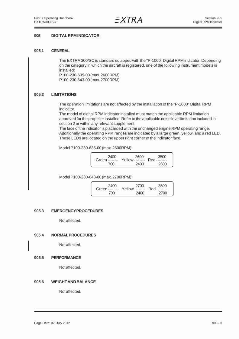
Section 905Digital RPM Indicator
Page Date: 29. February 2008 905 - 3
Pilot´s Operating HandbookEXTRA 300/SC
905 DIGITAL RPM INDICATOR
905.1 GENERAL
The EXTRA 300/SC is standard equipped with the "P-1000" Digital RPM indicator. Dependingon the category in which the aircraft is registered, one of the following instrument models isinstalled:P100-230-635-00 (max. 2600RPM)P100-230-643-00 (max. 2700RPM)
905.2 LIMITATIONS
The operation limitations are not affected by the installation of the "P-1000" Digital RPMindicator.The model of digital RPM indicator installed must match the applicable RPM limitationapproved for the propeller installed. Refer to the applicable noise level limitation included insection 2 or within any relevant supplement.The face of the indicator is placarded with the unchanged engine RPM operating range.Additionally the operating RPM ranges are indicated by a large green, yellow, and a red LED.These LEDs are located on the upper right corner of the indicator face.
Model P100-230-635-00 (max. 2600RPM):
Model P100-230-643-00 (max. 2700RPM):
905.3 EMERGENCY PROCEDURES
Not affected.
905.4 NORMAL PROCEDURES
Not affected.
905.5 PERFORMANCE
Not affected.
905.6 WEIGHT AND BALANCE
Not affected.
Green -------- Yellow -------- Red --------2400 2600 3500
700 2400 2600
Green -------- Yellow -------- Red --------2400 2700 3500
700 2400 2700
Page Date: 02. July 2012

Section 905Digital RPM Indicator
905 - 4 Page Date: 29. February 2008
Pilot´s Operating HandbookEXTRA 300/SC
905.7 DESCRIPTION AND OPERATION OF THE SYSTEM
The operation of the indicator is straight-forward. After power is supplied to the indicator, theengine is started, and the self tests are performed, the default display of the engine RPMappears on the display. The default display is insured via the use of internal timers that willrestore the display to the current RPM even in the event that one of the panel buttonsbecomes stuck or defective.Internally, two independent tachometers watch the pulses received from each magneto. Eachtachometer is accurate to less than 1 RPM and can be individually enabled/disabled viabuttons on the face of the indicator.
RPM RANGES
Engine operating ranges are indicated by the large green, yellow, and red LEDs.These LEDs are located on the upper right corner of the indicator face.
MAGNETO-CHECK
Three small LED magneto system alert indicator lights are located within the "Status" aera onthe upper left corner of the indicator face.The left and right red LED alert indicator lights, when illuminated, indicate, because of loss ofignition signal to the tachometer, a possible malfunction of the respective left or right magnetoignition system.While performing a magneto check during engine run-up, the red alert indicator lights willilluminate, thus identifying the grounding of the respective right or left magneto systems.
Magneto-Control
Operation placard:Press-and-release
Operation placard:Press-and-holdHours Clear Trap
L DIM R
Status
RPM-restriction
RPM range
buttons
Display
Page Date: 02. July 2012

Section 905Digital RPM Indicator
Page Date: 29. February 2008 905 - 5
Pilot´s Operating HandbookEXTRA 300/SC
Between the left and right magneto ignition system alert indicators is a yellow RPMsynchronization indicator. This small yellow indicator is illuminated when there is adifference of more than 50 RPM between the right and left tachometers.
This indicator also may flicker during extreme RPM excursions of the engine.
OPERATION BUTTONS
There are three panel buttons. Each button has two modes of operation.
PRESS-AND-HOLD operation mode
(press and hold for more than 2/3 of a second)
This operation mode is placarded above each button.(Hours, Clear,Trap)
Engine time (Hours)The left button, upon depression, will cause the tachometer to display the non-fractionalportion (0000.) of the current accumulated engine hours. When the button is released, thefractional part of the engine hours (.00) is displayed for a short period of time. The clock isstarted whenever the engine RPM exceeds 800 RPM and is recorded in real hours.
Clear (Clear)The middle button clears the RPM trap. During depression of the switch, the RPM trap iszeroed. When the button is released, the trap will record the current engine RPM.
Engine RPM (Trap)The right button will cause the tachometer to display the current contents of the RPM trap.This trap records the highest engine RPM achieved before the button was pressed.
PRESS-AND-RELEASE operation mode
(press and release in less than 2/3 of a second)
This operation mode is placarded below each button.( L , DIM , R )
Masks ( L , R )During normal operation, the tachometer presents the average of the left and right internaltachometers on the display. However, a mechanism exists to mask either tachometer fromthe display, leaving the remaining tachometer to determine magneto/ignition problems.
Quickly pressing and releasing the left button ( L ), causes the tachometer to mask the lefttachometer.
Page Date: 02. July 2012

Section 905Digital RPM Indicator
905 - 6 Page Date: 29. February 2008
Pilot´s Operating HandbookEXTRA 300/SC
Page Date: 02. July 2012
Quickly pressing and releasing the right button ( R ), causes the tachometer to mask theright tachometer.
Dimmer (DIM)Quickly pressing and releasing the middle button (DIM), causes the tachometer to alternatelydim or brighten the LED indicators (except the large red LED of the RPM Range).
905.8 HANDLING, SERVICING AND MAINTENANCE
Not affected.

Section 906Accelerometer TL-3424_EXT
Page Date: 29. February 2008 906 - 1
Pilot´s Operating HandbookEXTRA 300/SC
SECTION 906
ACCELEROMETER TL-3424_EXT
Table of Contents
Paragraph Page
SECTION 906 ACCELEROMETER TL-3424_EXT
906.1 GENERAL.........................................................................................................................906-3
906.2 LIMITATIONS ...................................................................................................................906-3
906.3 EMERGENCY PROCEDURES...........................................................................................906-3
906.4 NORMAL PROCEDURES .................................................................................................906-3
906.5 PERFORMANCE ..............................................................................................................906-3
906.6 WEIGHT AND BALANCE .................................................................................................906-4
906.7 DESCRIPTION .................................................................................................................906-4

Section 906Accelerometer TL-3424_EXT
906 - 2 Page Date: 29. February 2008
Pilot´s Operating HandbookEXTRA 300/SC
Left blank intentionally

Section 906Accelerometer TL-3424_EXT
Page Date: 29. February 2008 906 - 3
Pilot´s Operating HandbookEXTRA 300/SC
906 ACCELEROMETER TL-3424_EXT
906.1 GENERAL
The TL-3424_EXT accelerometer can be installed as an option in the 300/SC. It is used in a specialpassword protected configuration. This configuration helps the pilot to operate the aircraft withinlimits and allows supervising the operation by the aircraft manufacturer or e.g. an air race jury.
In detail the TL-3424_EXT accelerometer allows:
1. displaying current acceleration values,
2. displaying the minimum and maximum acceleration,
3. recording of all acceleration and speed values into the long-term memory,
4. recording of any exceedance of limits,
5. storing marks in the long-term memory,
6. warning the pilot before reaching load limits by a sound to hear on the head set,
7. indicating to the pilot, when he has exceeded a load or speed limit by a sound on the head set andthe G/V LIMITS WARNING LIGHT and
8. transferring recorded data to a computer.
906.2 LIMITATIONS
Markings and Placards: next to the red warning light.
906.3 EMERGENCY PROCEDURES
Not affected.
906.4 NORMAL PROCEDURES
Not affected.
906.5 PERFORMANCE
Not affected.
Page Date: 9. August 2007

Section 906Accelerometer TL-3424_EXT
906 - 4 Page Date: 29. February 2008
Pilot´s Operating HandbookEXTRA 300/SC
906.6 WEIGHT AND BALANCE
Refer to the Equipment List in Section 6 of this Handbook.
906.7 DESCRIPTION
The complete installation consists of:
1 TL-3424_EXT Accelerometer
2 G/V LIMITS WARNING LIGHT
3 USER BUTTON
4 CONTROL AND MARKER BUTTON
5 RS-232c (D-SUB 9 pins [female])
The TL-3424_EXT is complete weight acceleration management. The instrument incorporates ahigh-precision sensor for measuring acceleration in the vertical axis. The instrument alsoincorporates a sensor connected to the Pitot/static-system for measuring the indicated airspeed.

Section 906Accelerometer TL-3424_EXT
Page Date: 29. February 2008 906 - 5
Pilot´s Operating HandbookEXTRA 300/SC
It is possible to download the measured values from the instrument via the serial cable RS-232cinto a PC.
Pressing the Control and Marker Button enters marks into the memory records and enables theuser manual control of the memory recording.
The TL-3424_EXT checks all measured values at two levels - for a warning and an alarm limitsignalization. If the measured values are above the warning limit and below the alarm limit anintermitted sound is heard on the head set and the G/V LIMIT WARNING LIGHT flashes. If themeasured value exceeds the alarm limit a continuous sound is heard on the head set and the G/VLIMIT WARNING LIGHT illuminates continuously.
When the alarm warning has been activated, the instrument will display a service message afterthe next turn-on of the instrument to inform the user of the exceeded acceleration.
The USER BUTTON is programmed in the main set-up to display the minimum and maximumacceleration overview.
MEMORY
The following memory types are included in the TL-3424_EXT:
1.) A long-term memory storing the last recorded ~30 minutes (20,000 lines, entries every 0.1seconds).
2.) A „Scheck“-Report storing all cases of limit exceedance and the values in the immediate vicinityof this event (160 lines per case).
3.) A Line Report storing the last 64 values of limit exceedance (acceleration and speed).
A rolling type memory is used. This means, that in case the available memory capacity isexceeded, the oldest memory lines will be overwritten.
PRESETTINGS
The following values or definitions are preset in the special configuration of the TL-3424_EXT:
WARNING MAX +9.5 g
WARNING MIN -9.5 g
ALARM MAX +10.1 g
ALARM MIN -10.1 g
SPEED LIMIT 220 KIAS
Record begins at 50 KIAS
LANGUAGE English
Page Date: 9. August 2007
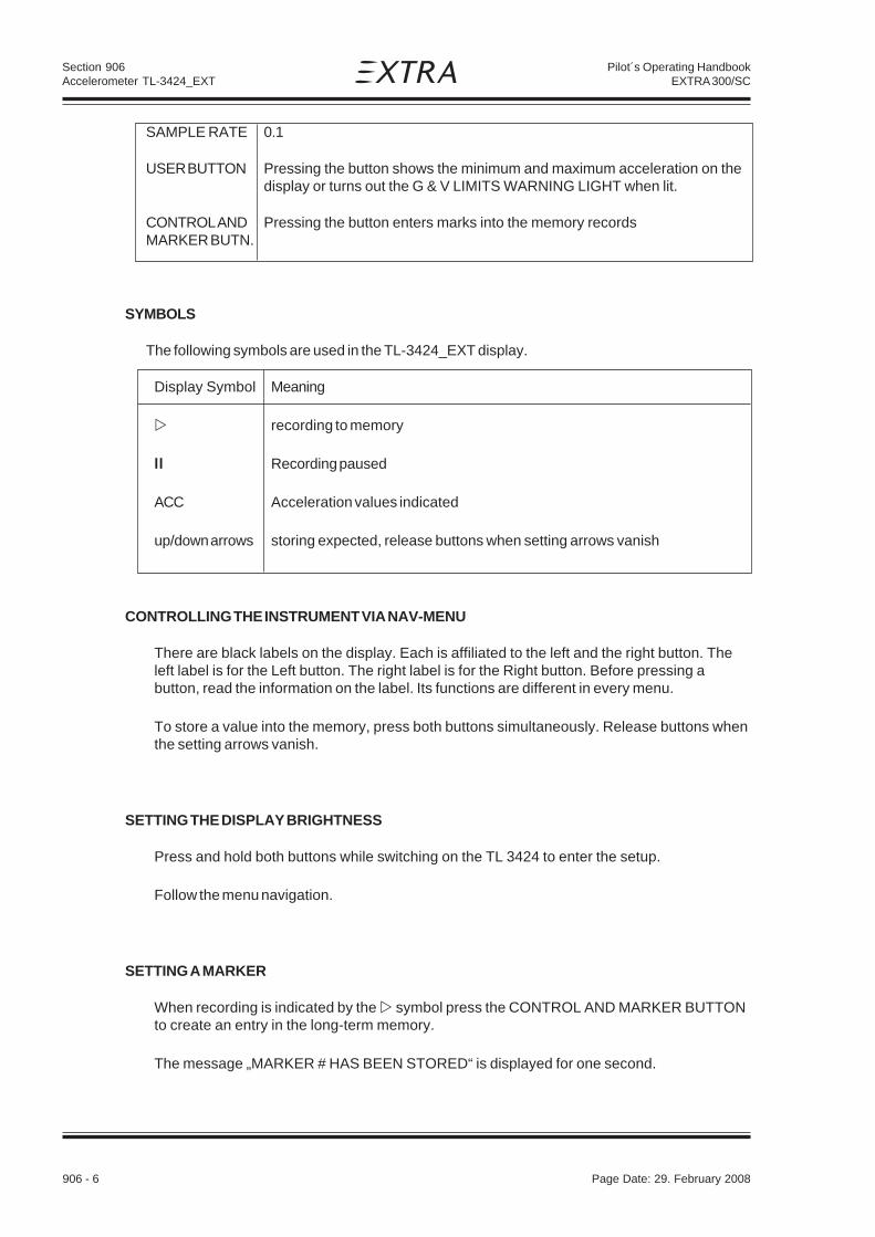
Section 906Accelerometer TL-3424_EXT
906 - 6 Page Date: 29. February 2008
Pilot´s Operating HandbookEXTRA 300/SC
SAMPLE RATE 0.1
USER BUTTON Pressing the button shows the minimum and maximum acceleration on thedisplay or turns out the G & V LIMITS WARNING LIGHT when lit.
CONTROL AND Pressing the button enters marks into the memory recordsMARKER BUTN.
SYMBOLS
The following symbols are used in the TL-3424_EXT display.
Display Symbol Meaning
recording to memory
ll Recording paused
ACC Acceleration values indicated
up/down arrows storing expected, release buttons when setting arrows vanish
CONTROLLING THE INSTRUMENT VIA NAV-MENU
There are black labels on the display. Each is affiliated to the left and the right button. Theleft label is for the Left button. The right label is for the Right button. Before pressing abutton, read the information on the label. Its functions are different in every menu.
To store a value into the memory, press both buttons simultaneously. Release buttons whenthe setting arrows vanish.
SETTING THE DISPLAY BRIGHTNESS
Press and hold both buttons while switching on the TL 3424 to enter the setup.
Follow the menu navigation.
SETTING A MARKER
When recording is indicated by the symbol press the CONTROL AND MARKER BUTTONto create an entry in the long-term memory.
The message „MARKER # HAS BEEN STORED“ is displayed for one second.

Section 907External Power
Page Date: 29. February 2008 907 - 1
Pilot´s Operating HandbookEXTRA 300/SC
SECTION 907
EXTERNAL POWER
Table of Contents
Paragraph PageSECTION 907 EXTERNAL POWER
907.1 GENERAL ....................................................................................................................... 907-3
907.2 LIMITATIONS .................................................................................................................. 907-3
907.3 EMERGENCY PROCEDURES ....................................................................................... 907-3
907.4 NORMAL PROCEDURES............................................................................................... 907-3
907.5 PERFORMANCE ............................................................................................................ 907-4
907.6 WEIGHT AND BALANCE ............................................................................................... 907-4
907.7 DESCRIPTION OF THE SYSTEM .................................................................................. 907-4
907.8 HANDLING, SERVICING AND MAINTENANCE ............................................................. 907-4

Section 907External Power
907 - 2 Page Date: 29. February 2008
Pilot´s Operating HandbookEXTRA 300/SC
Left blank intentionally

Section 907External Power
Page Date: 29. February 2008 907 - 3
Pilot´s Operating HandbookEXTRA 300/SC
907 EXTERNAL POWER
907.1 GENERAL
The EXTRA 300/SC can be equipped with an external power receptacle system. This systemprovides the capability to start the engine independent of the board battery and further allowsfeeding the electrical system for longer periods.
907.2 LIMITATIONS
The operation limitations are not affected due to the installation of the external powerreceptacle system. For the location of the external power receptacle and protection of theelectrical connection cable against overheating the following placard has to be attached onthe rear instrument panel with an indicator arrow to the receptacle:
907.3 EMERGENCY PROCEDURES
Not affected.
907.4 NORMAL PROCEDURES
The following starting procedures are recommended, however, the starting conditions maynecessitate some variation from these procedures.
1. Perform Pre-flight inspection.2. Set propeller governor control to "High RPM" position.3. Open throttle approximately 1/4 travel.
4. Master switch "OFF"
CAUTION
Risk of damage of electrical system due to reversion of polarity! Check correct polaritybefore connecting the power plug to the receptacle.
5. Put the external power plug into the board receptacle.
6. Turn boost pump "ON".
7. Move mixture control to "FULL RICH" until a slight but steady fuel flow is noted (approximately3 to 5 seconds) and return mixture control to "IDLE CUT-OFF".
Turn boost pump "OFF".
EXTERNAL POWER 12V
DO NOT CRANK FOR MORE THAN 10 SECONDS!Allow 20 seconds to cool-down between attempts. Repeat up to 6 times.
Then let starter cool for 30 minutes.

Section 907External Power
907 - 4 Page Date: 29. February 2008
Pilot´s Operating HandbookEXTRA 300/SC
CAUTION
Pay attention to objects and persons in the propeller operating area! Hold the canopytight!
8. Apply the brakes.
9. Engage starter.
10.When engine fires release the ignition switch back to "BOTH".
11.Pull the external power plug from the board receptacle.
12.Move mixture control slowly and smoothly to "FULL RICH".
13.Check the oil pressure gauge. If minimum oil pressure is not indicated within 30 seconds,shut off the engine and determine trouble.
14.Master switch "ON".
907.5 PERFORMANCE
Not affected.
907.6 WEIGHT AND BALANCE
Refer to the Equipment List in Section 6 of this Handbook.
907.7 DESCRIPTION OF THE SYSTEM
The external power receptacle with its spring-loaded door is attached left under the seatand reachable from outside. It is directly connected to the aircraft electrical system anddoes not feature an inverse-polarity protection (refer to Fig. 7-4). So it is advisable to checkcorrect polarity of the external power plug.During the engine start, the master switch has to be switched in "OFF"-position for thedisconnection of the battery from the aircraft electric circuit.
907.8 HANDLING, SERVICING AND MAINTENANCE
Not affected.

Section 908ARTEX ME-406 ELT
Page Date: 12. February 2010 908 - 1
Pilot´s Operating HandbookEXTRA 300/SC
SECTION 908
ARTEX ME-406 ELT
Table of Contents
Paragraph PageSECTION 908 ARTEX ME-406 ELT
908.1 GENERAL.........................................................................................................................908-3
908.2 LIMITATIONS ...................................................................................................................908-3
908.3 EMERGENCY PROCEDURES...........................................................................................908-4
908.4 NORMAL PROCEDURES .................................................................................................908-4
908.5 PERFORMANCE ..............................................................................................................908-4
908.6 WEIGHT & CENTER OF GRAVITY ...................................................................................908-4
908.7 SYSTEM DESCRIPTION ..................................................................................................908-5908.7.1 Switch Operation ..............................................................................................................908-5908.7.2 Self Test Mode .................................................................................................................. 908-5
908.8 HANDLING, SERVICING AND MAINTENANCE ................................................................908-6908.8.1 Transmitter Test ................................................................................................................908-6908.8.2 Self Test ...........................................................................................................................908-6

Section 908ARTEX ME-406 ELT
908 - 2 Page Date: 12. February 2010
Pilot´s Operating HandbookEXTRA 300/SC
Left blank intentionally

Section 908ARTEX ME-406 ELT
Page Date: 12. February 2010 908 - 3
Pilot´s Operating HandbookEXTRA 300/SC
908.1 GENERAL
To improve the passive security, the EXTRA 300/SC can be equipped with an optional EmergencyLocator Transmitter ARTEX ME-406.
In the event of a crash, the ME-406 activates automatically (automatic fixed „AF“ configuration), andtransmits the standard swept tone on 121.5 MHz lasting until battery power is gone. This 121.5 MHzsignal is mainly used to pinpoint the beacon during search and rescue operations. In addition, forthe first 24 hours of operation, a 406 MHz signal is transmitted at 50-second intervals. Thistransmission lasts 440 ms and contains identification data programmed into the beacon and isreceived by Cospas-Sarsat satellites. The transmitted data is referenced in a database (maintainedby the national authority responsible for ELT registration) and used to identify the beacon and owner.
When the ELT is activated, the buzzer ‘beeps’ and the panel LED pulses periodically. The timebetween pulses lengthen after a predetermined transmitter ‘on’ time.
N O T E
In October 2000 the International Cospas-Sarsat Program, announced at its 25th CouncilSession held in London, UK that it plans to terminate satellite processing of distress signalsfrom 121.5 and 243 MHz emergency beacons on February 1, 2009.
AccuracyDoppler positioning is employed using both 121.5 MHz and 406 MHz signals. Position accuracyof the 121.5 MHz signal is within an area of approximately 15-20 km radius about the transmitter.Due to the better signal integrity of the 406 MHz, its location accuracy is within about a 3 km radius.
908.2 LIMITATIONS
The operation limitations are not effected due to the installation of the ARTEX ME-406 ELT.
For the location and operation of the transmitter the following placards have to be attached to theaircraft:
(outside on the left fuselage in the vicinity of the ELT unit)
ELT (above the ELT circuit breaker; circuit breaker and placard installed up to SN SC027 only)
(next to the ELT remote switch)
(as close to the ELT remote switch as practical)
Page Date: 02. July 2012
Section 908ARTEX ME-406 ELT
908 - 4 Page Date: 12. February 2010
Pilot´s Operating HandbookEXTRA 300/SC
908.3 EMERGENCY PROCEDURES
• In case of a forced landing turn the remote switch in the rear panel to the "ON" position priorto touch down.
Although the ELT will be activated automatically after an aircraft accident or forced landing with highG-force,
• turn additionally the remote switch in the rear panel to the "ON" position.
After sighting rescue aircraft:
• Switch the remote switch to the "ARM" position to prevent radio interference.
• Attempt contact with rescue aircraft with the radio transceiver set to a frequency of 121.5MHz. If no contact is established, switch the remote switch to the "ON" positionimmediately.
If the function of the remote switch is in doubt proceed as follows:
• Use the unit master switch at the ELT unit analogously.
FUNCTION CHECK OF THE ELT
If the aircraft receiver is operable listen on 121.5 MHz for ELT transmission. Ensure that the antennais clear of obstruction.
908.4 NORMAL PROCEDURES
Not affected.
908.5 PERFORMANCE
Not affected.
908.6 WEIGHT & CENTER OF GRAVITY
Refer to the equipment list in Section 6 of this Handbook.

Section 908ARTEX ME-406 ELT
Page Date: 12. February 2010 908 - 5
Pilot´s Operating HandbookEXTRA 300/SC
908.7 SYSTEM DESCRIPTION
The ELT installation consists of the ELT unit and a buzzer, both fastened to the fuselage structurein front of the seat between the pedals, an antenna located on the main fuselage cover behind thecockpit, and a remote switch with LED indication located on the instrument panel. The switch hasthe positions ARM and ON.
908.7.1 SWITCH OPERATION
In a crash, an acceleration activated crash sensor (G-switch) turns the ELT ‘on’ automatically whenthe ELT experiences a change in velocity (or deceleration) of 4.5 fps ±0.5 fps. Activation is alsoaccomplished by means of the cockpit mounted remote switch or the switch on the ELT. Todeactivate the ELT set either switch to the ‘ON’ position, then back to ‘ARM’.
The ELT does not have an ‘OFF’ position. Instead, a jumper between two pins on the front D-subconnector must be in place for the G-switch to activate the unit. The jumper is installed on the matinghalf of the connector so that when the connector is installed, the beacon is armed. This allows thebeacon to be handled or shipped without ‘nuisance’ activation (front connector removed).
N O T E
The ELT can still be manually activated using the local switch on the front of the ELT. Careshould be taken when transporting or shipping the ELT not to move the switch or allowpacking material to become lodged such as to toggle the switch.
908.7.2 SELF TEST MODE
Upon turn-off (from „ON“ back to „ARM“ state), the ELT automatically enters a self-test mode thattransmits a 406 MHz test coded transmission that monitors certain system functions beforereturning to the ‘ARM’ mode. The transmission is ignored by any satellite that receives this signal,but the ELT requires it to check output power and correct frequency. If the ELT is left activated forapproximately 50 seconds or more, a distress signal is generated that is accepted by the satellites.
In addition to 121.5 and 406 MHz signal integrity, other operating parameters are checked duringthe self-test. Error codes are then generated if other problems are found. The error codes aredisplayed by a series of „blinks“ of the ELT LED, remote LED and audio indicator. See „InstalledTransmitter Test“ section for more details and a description of the error codes.
N O T E
Any time the ELT is activated, it is transmitting a 121.5 MHz distress signal. Therefore, allactivations of the ELT should be kept to a minimum. Local or national regulations maylimit testing of the ELT or impose special requirements or conditions to perform testing.For the „self test“, Artex recommends that the ELT be „ON“ for no more than 5 seconds.Testing should occur during the first 5 minutes after the hour.
Page Date: 02. July 2012

Section 908ARTEX ME-406 ELT
908 - 6 Page Date: 12. February 2010
Pilot´s Operating HandbookEXTRA 300/SC
908.8 HANDLING, SERVICING AND MAINTENANCE
908.8.1 TRANSMITTER TEST
ARTEX recommends that the ELT be tested every 1-2 months. Follow the steps outlined in the908.8.2 SELF TEST paragraph.
N O T E
The self-test time is accumulated in a register on the battery pack. The register recordsactivation time in 30 second increments so all activations will count as at least 30 seconds,even if the actual time is much less. Total allowable time is 60 minutes as determined byFAR 91.207 and RTCA DO-204. After this time has been accumulated a 7-flash error will bepresented after the self-test. The battery must be replaced at this point for the ELT toremain in compliance. Always follow ELT testing requirements per local or nationalauthorities.
Always perform the tests within the first 5 minutes of the hour. Notify any nearby control tower ofyour intentions, in accordance with AC 43.13. If outside of the US, always follow all local or nationalregulations for testing of ELT’s.
CAUTION
Do not allow test duration to exceed 5 seconds. A false alarm may be generated.
Any time the ELT is activated, it is transmitting a 121.5 MHz distress signal. After approximately50 seconds, a „live“ 406 MHz distress signal is transmitted and is considered valid by the satellitesystem.
Whenever the ELT is switched from „ON“ to „ARM“ a 406 MHz signal is transmitted, however, it isspecially coded as a „self test“ signal that is ignored by the COSPAS-SARSAT satellites.
908.8.2 SELF TEST
• Tune a receiver (usually the aircraft radio) to 121.5 MHz. Turn the ELT aircraft panel switch „ON“for about 1 second, then back to the „ARM“ position. The receiver should voice about 3 audiosweeps.
• At turn-off (back to ‘ARM’ state) the panel LED should present 1 pulse (buzzer will not sound for1 pulse). If more are displayed, determine the problem from the list below.
1 Flash Indicates that the system is operational and that no error conditions were found.
3 Flashes Bad load detected. Detects open or short condition on the antenna output orcable. These problems can probably be fixed by the installer.
• Check that the RF cable is connected and in good condition. Perform continuitycheck of center conductor and shield. Check for a shorted cable.
• Check for intermittent connection in the RF cable.
Page Date: 02. July 2012

Section 908ARTEX ME-406 ELT
Page Date: 12. February 2010 908 - 7
Pilot´s Operating HandbookEXTRA 300/SC
• If this error code persists there may be a problem with the antenna installation.This can be checked with a VSWR meter. Check the antenna for opens, shorts,resistive ground plane connection.
4 Flashes Low power detected. Occurs if output power is below about 33 dBm (2 watts) forthe 406 signal or 17 dBm (50 mW) for the 121.5 MHz output. Also may indicatethat 406 signal is off frequency. For this error code the ELT must be sent back forrepair or replacement.
5 Flashes Indicates that ELT has not been programmed, or is incorrectly programmed. Doesnot indicate erroneous or corrupted programmed data.
6 Flashes Indicates that the G-switch loop between pins 5 and 12 at the D-sub connector isnot installed. ELT will not activate during a crash.
• Check that the harness D-sub jumper is installed by verifying less than 1 ohm ofresistance between pins 5 and 12.
7 Flashes Indicates that the ELT battery has too much accumulated operation time (> 1hr,see below). Battery may still power ELT; however, it must be replaced to meetFAA specifications. May also indicate damage to the battery circuit.

Section 908ARTEX ME-406 ELT
908 - 8 Page Date: 12. February 2010
Pilot´s Operating HandbookEXTRA 300/SC
Left blank intentionally

Page Date: 12. February 2010 909 - 1
Section 909Electric Pedal Adjustment
Pilot´s Operating HandbookEXTRA 300/SC
SECTION 909
ELECTRIC PEDAL ADJUSTMENT
Table of Contents
Paragraph PageSECTION 909 ELECTRIC PEDAL ADJUSTMENT
909.1 GENERAL.........................................................................................................................909-3
909.2 LIMITATIONS ...................................................................................................................909-3
909.3 EMERGENCY PROCEDURES...........................................................................................909-3
909.4 NORMAL PROCEDURES .................................................................................................909-3
909.5 PERFORMANCE ..............................................................................................................909-3
909.6 WEIGHT AND BALANCE .................................................................................................909-3
909.7 DESCRIPTION OF THE SYSTEM ....................................................................................909-4
909.8 HANDLING, SERVICING AND MAINTENANCE ................................................................909-4

909 - 2 Page Date: 12. February 2010
Section 909Electric Pedal Adjustment
Pilot´s Operating HandbookEXTRA 300/SC
Left blank intentionally

Page Date: 12. February 2010 909 - 3
Section 909Electric Pedal Adjustment
Pilot´s Operating HandbookEXTRA 300/SC
909 ELECTRIC PEDAL ADJUSTMENT
909.1 GENERAL
To improve seat and control convenience, the EXTRA 300/SC can be equipped with anoptional electric pedal adjustment system. The pedal adjustment system provides an in-flightcapability to adjust the pedals according the pilots size and operation. For example a morerelaxed, stretched seating position for long cross-country flights is possible.
909.2 LIMITATIONS
An adjustment of the pedal position during takeoff and landing is not allowed. It isrecommended not to adjust the pedals when radio transmissions are made or when themagnetic direction indicator is used.
909.3 EMERGENCY PROCEDURES
Pedal Run-away
Pedal switch USE in reverse direction of run-away
if no effect:Pedal Circuit Breaker PULL
909.4 NORMAL PROCEDURES
On ground:
Rudder pedals ADJUST position using the pedal switchesCHECK full control inputs rudder and aileronCHECK full rudder deflection while braking
In flight:
Rudder pedals ADJUST position using the pedal switchesCHECK heels reach the pedal swivel axesand aileron control rods are free
909.5 PERFORMANCE
Not affected.
909.6 WEIGHT AND BALANCE
Not affected.

909 - 4 Page Date: 12. February 2010
Section 909Electric Pedal Adjustment
Pilot´s Operating HandbookEXTRA 300/SC
909.7 DESCRIPTION OF THE SYSTEM
The optional electrical pedal adjustment system which is guided on slide tubes, replaces themechanical rudder pedal adjustment. Such a pedal system consists of a foot rest and therudder pedal itself, including brake pedal and brake cylinder. An S-shaped cable leader isattached to the rudder pedal, through which the control cable runs from the rudder actuatorarm to the front cable attachment at the steel frame. The stepless pedal adjustment isrealized by electromechanical actuators which are controlled separately by switches on theinstrument panel (refer to figure below). The total travel of the system is limited to 11.8 cm(4.6'') by a front and a rear stop switch at the slide tube attachment. A full travel from themost rearward to the most forward position takes approximately 7 sec.
909.8 HANDLING, SERVICING AND MAINTENANCE
Not affected.
FORWARD
LH BACK RHPEDAL ADJUST
PEDAL-ADJUST
CONTROL SWITCHES CIRCUIT BREAKER 7,5A
7,5

Section 910AIRPLANES REGISTERED IN BRAZIL
Page Date: 5. September 2013 910- 1
Pilot´s Operating HandbookEXTRA 300SC
EASA ApprovedOn Behalf ofANAC of Brazil __________________________ Date: ___________
(Maximilian Maas)European Aviation Safety AgencyUnder EASA CSV Project Number 0010022327
SECTION 910
AIRPLANES REGISTERED IN BRAZIL AND OPERATING UNDER THEAGÊNCIA NACIONAL DE AVIAÇÃO CIVIL REQUIREMENTS
Table of Contents
Paragraph PageSECTION 910
910.1 GENERAL.........................................................................................................................910-3
910.2 LIMITATIONS ...................................................................................................................910-3910.2.1 KINDS OF OPERATIONAL LIMITS....................................................................................910-3910.2.2 OPERATING PLACARDS .................................................................................................910-4
910.3 EMERGENCY PROCEDURES...........................................................................................910-4
910.4 NORMAL PROCEDURES .................................................................................................910-4
910.5 PERFORMANCE ..............................................................................................................910-4
910.6 WEIGHT & CENTER OF GRAVITY ...................................................................................910-4
910.7 SYSTEM DESCRIPTION ..................................................................................................910-4
910.8 HANDLING, SERVICING AND MAINTENANCE ................................................................910-4

Section 910AIRPLANES REGISTERED IN BRAZIL
910 - 2 Page Date: 5. September 2013
Pilot´s Operating HandbookEXTRA 300SC
Left blank intentionally

Section 910AIRPLANES REGISTERED IN BRAZIL
Page Date: 5. September 2013 910- 3
Pilot´s Operating HandbookEXTRA 300SC
910.1 GENERAL
This supplement is approved by the EASA on behalf of the „Agência Nacional de Aviação Civil“– ANAC for Brazilian registered aircraft, in accordance with the „Regulamento Brasileiro daAviação Civil“ – RBAC 21, Section 21.29.
The information contained within this supplement is to be used in conjunction with the basic AFM/POH and supplements. The information contained herein supplements or supersedes that in thebasic manual and approved supplements only in those areas indicated.
The following POH/AFM supplements are ANAC approved:
Section Title901 Steerable Tail Wheel902 Smoke System903 BECKER ATC 4401 Transponder904 BECKER BXP 6401 Transponder905 Digital RPM Indicator906 Accelerometer TL-3424_EXT907 External Power908 ARTEX ME-406 ELT909 Electric Pedal Adjustment
Compliance with the limitations contained in the basic manual and approved supplements ismandatory.
Foreign operating rules and any references to such rules in the basic manual and approvedsupplements are not applicable in Brazil. The aircraft must be equipped and operated in accordancewith Brazilian operating requirements.
N O T E
A Kinds of Operation Equipment List may not necessarily apply in Brazil.
910.2 LIMITATIONS
910.2.1 KINDS OF OPERATIONAL LIMITS
Operation is limited to VFR-day. Use of GPS is prohibited as primary means for navigation. GPSmay only be used as supplemental means for navigation.
Wide Area Augmentation System (WAAS) functionality:
Since the WAAS is not available in Brazil, any kind of Global Navigation Satellite System (GNSS)approaches is prohibited even though a GPS System installed may be capable of receiving WAAS.
The following equipment list identifies the systems and equipment upon which certification waspredicated. The following systems and items of equipment must be installed and operable for theparticular kind of operation indicated:

Section 910AIRPLANES REGISTERED IN BRAZIL
910 - 4 Page Date: 5. September 2013
Pilot´s Operating HandbookEXTRA 300SC
NORMAL ACROBATIC
Wing-tip strobe lights 2 2
910.2.2 OPERATING PLACARDS
The following placard has to be attached to the aircraft replacing the related placard in Englishlanguage:
COMBUSTÍVEL (adjacent to both wing fuel tank filler caps as well asAVGAS 100/100LL front and rear fuselage center fuel tank filler cap)
910.3 EMERGENCY PROCEDURES
Not affected.
910.4 NORMAL PROCEDURES
Not affected.
910.5 PERFORMANCE
Not affected.
910.6 WEIGHT & CENTER OF GRAVITY
Not affected.
910.7 SYSTEM DESCRIPTION
Not affected.
910.8 HANDLING, SERVICING AND MAINTENANCE
Not affected.

Section 911f.u.n.k.e TRT800H Transponder
Page Date: 19. May 2014 911 - 1
Pilot´s Operating HandbookEXTRA 300SC
Table of Contents
Paragraph Page
SECTION 911
f.u.n.k.e. TRT800H Transponder
911.1 GENERAL......................................................................................................................... 911-3911.1.1 Features ........................................................................................................................... 911-3911.1.2 Operation .......................................................................................................................... 911-4911.1.3 Display-Contrast ............................................................................................................... 911-6911.1.4 Flight-ID (FID) ................................................................................................................... 911-6911.1.5 Display Flight-ID ............................................................................................................... 911-6911.1.6 Configure Flight-ID ............................................................................................................ 911-6911.1.7 Transponder Mode selection ............................................................................................. 911-7911.1.8 Squawk-Setting................................................................................................................. 911-7911.1.9 VFR – Squawk .................................................................................................................. 911-8911.1.10 ID – Special Position Identification (SPI): “Squawk Ident” .................................................. 911-8911.1.11 Error-Codes ...................................................................................................................... 911-8
911.2 LIMITATIONS ................................................................................................................... 911-9
911.3 EMERGENCY PROCEDURES........................................................................................... 911-9911.3.1 Important Codes ............................................................................................................... 911-9
911.4 NORMAL PROCEDURES ................................................................................................. 911-9
911.5 PERFORMANCE .............................................................................................................. 911-9

Section 911f.u.n.k.e TRT800H Transponder
911 - 2 Page Date: 19. May 2014
Pilot´s Operating HandbookEXTRA 300SC
Left blank intentionally
Section 911f.u.n.k.e TRT800H Transponder
Page Date: 19. May 2014 911 - 3
Pilot´s Operating HandbookEXTRA 300SC
911.1 GENERAL
N O T E
In order to operate the Mode S transponder it is necessary to request an ICAO 24-bit AircraftAddress at the responsible national aviation authorities. The received Code is assignedto the specific transponder/aircraft and must be configured within the transponder. The24-bit address is stored in an external memory which allows the transponder beingexchanged without requiring any further configuration.
N O T E
The TRT800H owner accepts all responsibility for obtaining the proper license beforeusing the transponder. For this purpose and for detailed and further information refer tof.u.n.k.e. TRT800H Operation and Installation Manual (Doc. No. 03.2125.010.71e).
911.1.1 FEATURES
• Class 1 Level 2es non-diversity Mode S transponder for ground based interrogations at 1030 MHzand response at 1090 MHz
• Replies to (Secondary) Radar Interrogations
Mode A replies with a Squawk (one of 4096 possible Codes; e.g. flight plan number, Squawkassigned by a controller or the VFR Squawk 7000)
Mode C replies, including encoded flight level
Mode S replies, including aircraft address and flight level
Extended Squitter, containing additional information on position and velocity
• IDENT capability for activating the „Special Position Identification“- Pulse (SPI) for 18 seconds,which is requested by the Controller „Squawk Ident“
• Display information contains Squawk code, mode of operation and pressure altitude.
• Temperature compensated high precision piezo-resistive pressure sensor
• 8 storable entries for AA-/AC-Code, FID, Ground-Switch, RI-Code and GPS-/Interface-setting(stored in external memory TRT800EMxx)

Section 911f.u.n.k.e TRT800H Transponder
911 - 4 Page Date: 19. May 2014
Pilot´s Operating HandbookEXTRA 300SC
911.1.2 OPERATION
CONTROLS

Section 911f.u.n.k.e TRT800H Transponder
Page Date: 19. May 2014 911 - 5
Pilot´s Operating HandbookEXTRA 300SC
I/O ON/OFFSwitch ON: press I/O button for approx. 0,5 sSwitch OFF: press I/O button for approx. 3 s
VFR VFRactivate/deactivate VFR Squawk (press shortly)store active Squawk as VFR/VFRW-Squawk (press button 3 s)
CHANGEchange between active and standby-Squawkworks as cursor back button (opposite function of the cursor button) during entering values andalso for navigating backwards through the configuration menu.
ID IDENT„Squawk Ident“, sends Ident marking (SPI) for 18 sEnter Flight-ID (FID) setup (in standby mode, press button for approx. 5s)
MODE MODESelect transponder operational mode
CURSORSet position of Cursor
Rotary KnobAdjust/Enter values at current cursor position, select options; set standby Squawk
DISPLAY

Section 911f.u.n.k.e TRT800H Transponder
911 - 6 Page Date: 19. May 2014
Pilot´s Operating HandbookEXTRA 300SC
911.1.3 DISPLAY-CONTRAST
In active mode (not standby) press for 2 s.
Display indicates “CON” Now adjust contrast (CON) with rotary knob.
Return to normal operation: press or wait 5 s.
911.1.4 FLIGHT-ID (FID)
The FID is an identifier required for Mode S Operation. During future application of flight plans aFID could be assigned on a per flight basis. If no FID is assigned (today’s normal case) theregistration marking of the aircraft should be used as FID. The FID should not contain dashesor blanks. The FID must not be confused with the 24-bit Aircraft Address.
911.1.5 DISPLAY FLIGHT-ID
Press MODE (repeatedly) until „STBY“ appears
Press and hold ID while a counter is shown beside the active squawk.
During a few seconds Flight Identification is displayed.
911.1.6 CONFIGURE FLIGHT-ID
Press MODE (repeatedly) until „STBY“ appears
Press and hold ID while a counter is shown beside the active squawk.
Release ID when “CHANGE FID” is displayed
N O T E
Enter FID left-aligned, without any blanks or dashes (!), e.g. 12345621DEFAV for themarking D-EFAV. The last remaining digits shall be filled with blanks.
Enter Flight-Id with and rotary knob.
Press MODE to save and return to STBY
Please refer to TRT800H Operation and Installation Manual (Doc. No. 03.2125.010.71e) Section4.5.4 for configuration of the 24-bit Address (AA) and Aircraft Category (AC).
Section 911f.u.n.k.e TRT800H Transponder
Page Date: 19. May 2014 911 - 7
Pilot´s Operating HandbookEXTRA 300SC
911.1.7 TRANSPONDER MODE SELECTION
Press MODE (repeatedly) to select from following Modes:
• STBY „Standby“
Transponder does not respond to any interrogation. Squitter and ADS-B output is not active.
• A C S „Mode A+C+S“
Standard condition; transponder responds to mode A, C and S interrogations.
• A – S „Mode A+S, no C“
Altitude is not transmitted (neither on C nor on S requests). All other Mode-S data as well as Mode-A replies are transmitted.
If no 24-bit address (AA) was defined or entered as “000000“ the transponder operates as a ModeA/C transponder, in that case the following Modes are possible apart from Standby:
• A C – „Mode A+C“
Transponder replies only on Mode A and Mode-C interrogations.
• A – – „Mode A“
Transponder replies only on Mode A interrogations.
N O T E
In STBY (Standby) mode, all transponder transmissions are disabled completely! There-fore, the transponder is not visible in this mode to air traffic control or the anti-collisionsystems onboard other aircraft.Never use the STBY mode in flight unless you are requested to do so by air traffic control.Always remember to put the transponder in active mode prior to take off!
911.1.8 SQUAWK-SETTING
The active Squawk is displayed in the upper line, while the standby Squawk is presented at the lowerline.
Setting the Standby Squawk:
• Press to set the cursor („^“), turn rotary knob to set numbers of the standby Squawk.
• Press to activate the Standby Squawk (this moves the current active Squawk into Standby)

Section 911f.u.n.k.e TRT800H Transponder
911 - 8 Page Date: 19. May 2014
Pilot´s Operating HandbookEXTRA 300SC
911.1.9 VFR – SQUAWK
The transponder features a user-defined squawk code for VFR-flight (factory setting: 7000):
• Activate VFR-Squawk:
Press VFR („VFR“ is indicated), now the active Squawk is moved into Standby but not visiblebecause the indication of the Standby Squawk is overlapped by „VFR“
• Display Standby Squawk:
Press VFR or or use the rotary knob (the VFR Squawk remains active!)
• Now the Standby Squawk can be adjusted by using the rotary knob and activated with .
• In order to store the current active Squawk as new VFR-Squawk (replacing the factory setting 7000):
Press and hold VFR until an „S“ is indicated (approx. 3 s); after releasing the button „VFR“ is shown.
911.1.10 ID – SPECIAL POSITION IDENTIFICATION (SPI): “SQUAWK IDENT”
Press ID to activate transmission of the special position identification pulse with every reply within18 seconds; “IDT” appears on the display
By pressing ID a special position identification pulse (SPI) is transmitted with every reply within 18seconds, which causes an accented marking on the controller’s screen. The „Special PositionIdentification“ has to be activated after the „Squawk Ident“ request of the controller.
911.1.11 ERROR-CODES
eulaV gninaeM skrameR
LLP rorrELLP rorrElanretnI
XRT eruliaFtimsnarT gniriwdnaannetnakcehC
CD egatlovlanretniwoL rorrelanretnI
GPF eruliaF-AGPF rorrelanretnI
TAB wolootrewoPyrettaB tluafrotareneg/yrettabebyam

Section 911f.u.n.k.e TRT800H Transponder
Page Date: 19. May 2014 911 - 9
Pilot´s Operating HandbookEXTRA 300SC
911.2 LIMITATIONS
Not applicable.
911.3 EMERGENCY PROCEDURES
911.3.1 IMPORTANT CODES
7600 Loss of communications.
7500 Hijacking.
7700 Emergency (All secondary surveillance radar sites are ready to receive this code at alltimes).
See the Airman’s Information Manual (AIM) for a detailed explanation of identification codes.
911.4 NORMAL PROCEDURES
Not applicable.
911.5 PERFORMANCE
Not applicable.

Section 911f.u.n.k.e TRT800H Transponder
911 - 10 Page Date: 19. May 2014
Pilot´s Operating HandbookEXTRA 300SC
Left blank intentionally

Section 912Cabin Heating System
Page Date: 19. May 2014 912 - 1
Pilot´s Operating HandbookEXTRA 300/SC
Table of Contents
Paragraph Page
SECTION 912
CABIN HEATING SYSTEM
912.1 GENERAL.........................................................................................................................912-3
912.2 LIMITATIONS ...................................................................................................................912-3
912.3 EMERGENCY PROCEDURES...........................................................................................912-3
912.4 NORMAL PROCEDURES .................................................................................................912-3
912.5 PERFORMANCE ..............................................................................................................912-3
912.6 WEIGHT & CENTER OF GRAVITY ...................................................................................912-3
912.7 SYSTEM DESCRIPTION ..................................................................................................912-4
912.8 HANDLING, SERVICING AND MAINTENANCE ................................................................912-4

Section 912Cabin Heating System
912 - 2 Page Date: 19. May 2014
Pilot´s Operating HandbookEXTRA 300/SC
Left blank intentionally
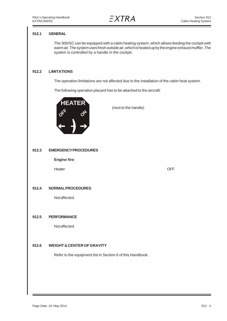
Section 912Cabin Heating System
Page Date: 19. May 2014 912 - 3
Pilot´s Operating HandbookEXTRA 300/SC
912.1 GENERAL
The 300/SC can be equipped with a cabin heating system, which allows feeding the cockpit withwarm air. The system uses fresh outside air, which is heated up by the engine exhaust muffler. Thesystem is controlled by a handle in the cockpit.
912.2 LIMITATIONS
The operation limitations are not affected due to the installation of the cabin heat system.
The following operation placard has to be attached to the aircraft:
(next to the handle)
912.3 EMERGENCY PROCEDURES
Engine fire:
Heater OFF
912.4 NORMAL PROCEDURES
Not affected.
912.5 PERFORMANCE
Not affected.
912.6 WEIGHT & CENTER OF GRAVITY
Refer to the equipment list in Section 6 of this Handbook.
HEATER
ONOFF

Section 912Cabin Heating System
912 - 4 Page Date: 19. May 2014
Pilot´s Operating HandbookEXTRA 300/SC
912.7 SYSTEM DESCRIPTION
On the left front engine baffle a 3” air intake (1, figure 1) with screen is positioned. From there freshair is routed through a 3" ducting (2) to the exhaust muffler heat shroud (3), where it is heated up.A selector box (4) is placed on the engine side of the firewall. Using the main handle (9) the warmair can there be guided into the cockpit or dumped overboard. A distribution box (5) is located onthe aft side of the firewall. The distribution box incorporates the flanges for the 2" ducting (6) to theair outlets (7) at the pilot’s feet.
Legend:1 air intake2 3" ducting3 exhaust muffler heat shroud4 selector box5 distribution box6 2" ducting7 air outlets8 Bowden cable9 control handle
Firewall
fwd
1
2
3
4
5
6
7
8
9
Figure 1
912.8 HANDLING, SERVICING AND MAINTENANCE
Not affected.

Section 913KANNAD AF 406 ELT
Page Date: 19. May 2014 913 - 1
Pilot´s Operating HandbookEXTRA 300SC
Table of Contents
Paragraph Page
SECTION 913
KANNAD 406 AF COMPACT/INTEGRA ELT
913.1 GENERAL.........................................................................................................................913-3
913.2 LIMITATIONS ...................................................................................................................913-3
913.3 EMERGENCY PROCEDURES...........................................................................................913-4
913.4 NORMAL PROCEDURES .................................................................................................913-4
913.5 PERFORMANCE ..............................................................................................................913-5
913.6 WEIGHT & CENTER OF GRAVITY ...................................................................................913-5
913.7 SYSTEM DESCRIPTION ..................................................................................................913-5913.7.1 Switch Operation ..............................................................................................................913-6
913.8 HANDLING, SERVICING AND MAINTENANCE ................................................................913-6913.8.1 Periodic Inspection ........................................................................................................... 913-6913.8.2 Battery Replacement ........................................................................................................913-7

Section 913KANNAD AF 406 ELT
913 - 2 Page Date: 19. May 2014
Pilot´s Operating HandbookEXTRA 300SC
Left blank intentionally

Section 913KANNAD AF 406 ELT
Page Date: 19. May 2014 913 - 3
Pilot´s Operating HandbookEXTRA 300SC
913.1 GENERAL
To improve the passive security, the EXTRA 300SC can be equipped with an optional EmergencyLocator Transmitter KANNAD AF 406 COMPACT or INTEGRA ELT.
In the event of a crash, the AF 406 activates automatically (automatic fixed „AF“ configuration), andtransmits the standard swept tone on 121.5 MHz lasting until the battery is depleted. This 121.5MHz signal is mainly used to pinpoint the beacon during search and rescue operations. In addition,for the first 24 hours of operation, a 406 MHz signal is transmitted at 50-second intervals. Thistransmission lasts 440 ms and contains identification data programmed into the beacon and isreceived by Cospas-Sarsat satellites. The transmitted data is referenced in a database (maintainedby the national authority responsible for ELT registration) and used to identify the beacon and owner.
When the ELT is activated, the panel LED pulses periodically. The time between pulses lengthensafter a predetermined transmitter ‘on’ time.
N O T E
In October 2000 the International Cospas-Sarsat Program, announced at its 25th CouncilSession held in London, UK that it plans to terminate satellite processing of distress signalsfrom 121.5 and 243 MHz emergency beacons on February 1, 2009.
ACCURACY
Doppler positioning is employed using both 121.5 MHz and 406 MHz signals. Position accuracyof the 121.5 MHz signal is within an area of approximately 15-20 km radius about the transmitter.Due to the better integrity of the 406 MHz signal, its location accuracy is within about a 3 km radius.
913.2 LIMITATIONS
The operation limitations are not affected by the installation of the KANNAD AF 406 COMPACT orINTEGRA ELT.
For the operation of the transmitter the following placard is on the front face of the remote switch:
(on the ELT remote switch)

Section 913KANNAD AF 406 ELT
913 - 4 Page Date: 19. May 2014
Pilot´s Operating HandbookEXTRA 300SC
913.3 EMERGENCY PROCEDURES
• In case of a forced landing switch the remote switch in the instrument panel to the "ON"position prior to touch down.
Although the ELT will be activated automatically after an aircraft accident or forced landing with highG-force,
• switch additionally the remote switch in the rear panel to the "ON" position.
After sighting rescue aircraft:
• Switch the remote switch to the "ARM" position to prevent radio interference.
• Attempt contact with rescue aircraft with the radio transceiver set to a frequency of 121.5MHz. If no contact is established, switch the remote switch to the "ON" positionimmediately.
If the function of the remote switch is in doubt proceed as follows:
• Use the master switch at the ELT unit analogously.
FUNCTION CHECK OF THE ELT
• If the aircraft receiver is operable, check ELT function by listening on 121.5 MHz for ELTtransmission. Ensure that the ELT antenna is clear of any obstructions.
913.4 NORMAL PROCEDURES
It is recommended by the manufacturer to test the ELT to detect any possible failure.
An operational check must be performed regularly by a pilot or maintenance personnel from thecockpit (Remote Control Panel). It is recommended to perform a self-test once a month but itshould not be done more than once a week.
Each self-test consumes energy from the battery. Should self-tests be carried out more often thanthe maximum allowed, the battery life-time might be shorter than specified.
SELF-TEST PROCEDURE
• Check that the antenna is correctly connected
Do not perform self-test without antenna connected.
• Tune aircraft radio to 121.5 MHz and adjust volume to ensure you can hear it.
• Switch from position „OFF“ to position „ARM“ or press RESET & TEST on the RemoteControl Panel (ensure that the ELT switch is in position „ARM“).

Section 913KANNAD AF 406 ELT
Page Date: 19. May 2014 913 - 5
Pilot´s Operating HandbookEXTRA 300SC
Close to the end of the self-test a short (3-4 sweeps) 121.5 transmission is made.
• confirm this on the aircraft radio.
• After a few seconds, the test result is displayed with the red visual indicator:
• One long flash indicates that the system is operational and that no error conditions werefound.
• A series of short flashes indicates the test has failed.
Remark: The number of flashes gives an indication of the faulty parameter detected during the self-test.
sehsalF gninaeM
1+3 egatloVyrettaBwoL
2+3 rewoPFRwoL
3+3 )ycneuqerFytluaF(gnikcoLOCVytluaF
4+3 demmargorPnoitacifitnedIoN
If self-test fails, contact the distributor as soon as possible. Unless a waiver is granted, flight shouldbe cancelled.
913.5 PERFORMANCE
Not affected.
913.6 WEIGHT & CENTER OF GRAVITY
Refer to the equipment list in Section 6 of this Handbook.
913.7 SYSTEM DESCRIPTION
The ELT installation consists of the ELT unit fastened to the fuselage structure in front of the controlstick between the pedals, an antenna located on the main fuselage cover behind the cockpit, anda remote switch with a red visual indicator (LED) located on the instrument panel. The remote switchhas the positions 'ON', 'ARMED' and 'RESET/TEST'.The switch on the ELT unit has the positions'ARM', 'OFF' and 'ON'.

Section 913KANNAD AF 406 ELT
913 - 6 Page Date: 19. May 2014
Pilot´s Operating HandbookEXTRA 300SC
913.7.1 SWITCH OPERATION
In a crash, an acceleration activated crash sensor (G-switch) turns the ELT ‘on’ automatically.Activation is also accomplished by switching the cockpit mounted remote switch or the switch onthe ELT to the 'ON' position. To deactivate the ELT switch the switch on the ELT unit to the ‘OFF’position.
N O T E
With remote switch disconnected or during transport the ELT can still be manuallyactivated using the local switch on the front of the ELT. Care should be taken whentransporting or shipping the ELT not to move the switch or allow packing material tobecome lodged such as to toggle the switch.
It is possible to stop the ELT in case of unintentional activation:
• Switch to 'OFF'.
Regulations state that no transmission must be interrupted unless all means are used to contactand inform the Air Traffic Controller of this action.
N O T E
As 406 MHz transmission is effective 50 seconds after the ELT activation, if it is switchedoff within this delay, no further radio contact will be necessary.
913.8 HANDLING, SERVICING AND MAINTENANCE
Refer to the following applicable manufacturer instructions for further detailed information or whenworking on the Kannad 406 AF ELT:
• Installation and Operation Manual 406 AF-COMPACT ELT (P/N: DOC08038E Rev. 04)
• Initial Installation Manual 406 AF-INTEGRA ELT (P/N: DOC09081C Rev. 02)
• Operation Manual 406 AF-INTEGRA ELT (P/N: DOC09078C Rev. 02)
Manufacturer:
Kannad Aviation (McMurdo Group)Orolia SASZ.I. des 5 Chemins BP 2356520 Guidel (F)
913.8.1 PERIODIC INSPECTION
Depending if the ELT is opened or not, PART 145 or FAR 145 (or equivalent) may be required. Referto local regulations.

Section 913KANNAD AF 406 ELT
Page Date: 19. May 2014 913 - 7
Pilot´s Operating HandbookEXTRA 300SC
913.8.2 BATTERY REPLACEMENT
Carried out by an accredited PART 145 or FAR 145 (or equivalent) maintenance station.
BATTERY REPLACEMENT REQUIREMENTS
Battery replacement is mandatory:
• after more than 1 hour of real transmission (cumulated duration);
• before or on the battery expiration date;
• after use in an emergency;
• after an inadvertant activation of unknown duration.
Only an original and approved battery pack included in battery KIT BAT200 (P/N S1840510-01)supplied by KANNAD must be installed. [SAFT-FRIWO , Lithium Manganese Dioxide, 2 x M20 (D-type) cells]
KANNAD refuses all responsibility and invalidates all warranty should other packs be installed.
Battery packs or KITs are available from any KANNAD distributor or dealer.
A list of distributors is available on http://www.kannad.com

Section 913KANNAD AF 406 ELT
913 - 8 Page Date: 19. May 2014
Pilot´s Operating HandbookEXTRA 300SC
Left blank intentionally