i-joist diaphragm systems: performance trends observed with full-scale testing
DESCRIPTION
The article is derived from the Summer 2010 issue of Wood Design Focus, a journal published by the Forest Products Society. To access the publication, go to www.forestprod.org/wdfTRANSCRIPT
tension/compression chords or struts. Wood struc-tural panel sheathing combines with joists to serve as
the “web” that transfers shear. Joists provide out-of-plane stiffening and load transfer between discrete panel sheathing elements. This makes sheathing-to-framing attachment a critical element that often de-
fines shear capacity of the assembly. Wood structural panel diaphragms are normally
designed in accordance with provisions of the Inter-
national Building Code (IBC) (International Code
Council 2009) and the Special Design Provisions for
Wind and Seismic (SPDWS) (American Wood Council 2008). Tables, like 2009 IBC Table 2306.2.1(1), were first developed in the 1950s and have evolved over time (Countryman 1952 and 1955, Peterson 1983, Tissell 1967, Tissell and Elliott 2004). The original rationalizations for these tables were based on an
analysis of sheathing and attachment schedules for lumber-framed diaphragms with plywood panel sheathing. They have been subsequently modified based on results from a variety of full-scale test pro-grams that introduced additional materials, failure modes, and design considerations. Original I-joist framing products used laminated
veneer lumber (LVL) or sawn lumber flanges with thicknesses of 1.5 in. or greater. These thicknesses were consistent with 2 in. nominal material typically used to “block” a lumber diaphragm and exceeded specified minimum fastener penetration require-
ments. Provided that the diaphragm configuration adhered to the manufacturer’s fastener spacing rec-ommendations to avoid splitting and the flange mate-rial could rationalize equivalent fastener performance to an appropriate sawn lumber species, it was judged that application of shear design tables like 2009 IBC Table 2306.2.1(1) could be extended to these prod-
ucts. As I-joist products are optimized, it has become
common to see LVL flange thicknesses less than 1.5 in. The industry has long recognized that reducing flange thickness beyond a certain threshold has the potential to adversely impact sheathing nail embed-
Summer 2010 9
Abstract
Pre-fabricated wood I-joists are routinely used to
construct roof and floor systems in modern light-frame wood construction. One of the primary func-
tions of a light-frame floor or roof is to serve as a dia-phragm that collects in-plane lateral load and trans-fers it to the shear walls and foundation elements. Since the existing diaphragm design provisions con-tained within the model building codes are based on
a combination of testing and analysis conducted with sawn lumber framing, designers often question
whether they can be reasonably applied to dia-phragms framed with I-joists. This article summarizes some of the rationalization and limitations associated with I-joist framing for diaphragm construction. Per-
formance trends and observations are presented based on one manufacturer’s experience with 41 full-
scale I-joist diaphragm tests conducted in accordance with ASTM E455 (ASTM 2004).
Introduction
Modern light-frame roof and floor systems rou-tinely combine pre-fabricated wood I-joists with wood structural panel sheathing. A primary function of a light-frame floor or roof is to serve as a dia-phragm that collects lateral load and transfers it to the shear walls and foundation. Diaphragm design provisions for light-frame wood construction have
been successfully employed for decades and were originally developed for lumber framing. Designers often wonder if they are equally applicable to dia-phragms framed with wood I-joists. The objective of this article is to provide some insight into how shear capacities are rationalized for I-joist diaphragms and to summarize potentially useful trends observed with
full-scale testing.
Diaphragm Design
Diaphragms are typically modeled as deep, in-plane beams. Perimeter framing is designed to act as
I-Joist Diaphragm Systems: Performance Trends
Observed with Full-Scale Testing
Ned Waltz, P.E., S.E.C.B., and Dr. J. Daniel Dolan, P.E.
10 WOOD DESIGN FOCUS
ment and split resistance to the point where dia-phragm capacity may be influenced. International Code Council Evaluation Service (ICC-ES) acceptance criterion for I-joists defines that threshold as 1-5/16 in. (ICC-ES 2010) based primarily on sheathing nail embedment calculations (APA 2007). I-joist products with flanges thinner than 1-5/16 in. are subsequently required to conduct “full-scale horizontal diaphragm
testing” to rationalize performance. At present, at least two manufacturers have con-
ducted full-scale diaphragm testing to investigate performance of I-joist product lines with flange thick-nesses less than 1-5/16 in. Both manufacturers have developed related design recommendations and limi-tations that are included in their evaluation reports.
In general, the manufacturers have proven equiva-lence to a subset of the current diaphragm design tables for sawn lumber. They generally do not permit
thinner flanged I-joist products to be used in the highest load applications that require the closest sheathing attachment schedules.
Full-Scale Testing
At present, Weyerhaeuser has conducted 41 full-scale tests on I-joist diaphragm systems framed with
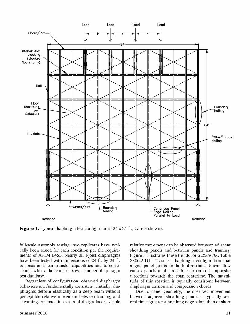
I-joists with LVL flange thicknesses between 1-1/8 and 1-1/4 in. Figures 1 and 2 illustrate test condi-tions chosen to be consistent with requirements of ASTM E455 (ASTM 2004) and benchmark testing conducted with sawn lumber (Countryman 1955). A variety of I-joist materials, sheathing products, dia-phragm configurations, sheathing fasteners, and fas-
tening schedules have been tested to verify shear transfer and deformation performance capabilities. Given the high cost and relatively low variability of
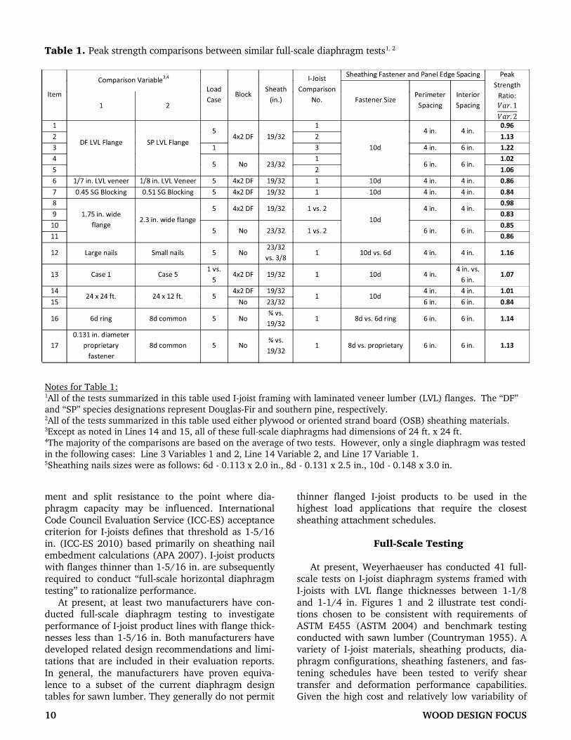
Table 1. Peak strength comparisons between similar full-scale diaphragm tests1, 2
Notes for Table 1:1All of the tests summarized in this table used I-joist framing with laminated veneer lumber (LVL) flanges. The “DF”
and “SP” species designations represent Douglas-Fir and southern pine, respectively. 2All of the tests summarized in this table used either plywood or oriented strand board (OSB) sheathing materials. 3Except as noted in Lines 14 and 15, all of these full-scale diaphragms had dimensions of 24 ft. x 24 ft. 4The majority of the comparisons are based on the average of two tests. However, only a single diaphragm was tested
in the following cases: Line 3 Variables 1 and 2, Line 14 Variable 2, and Line 17 Variable 1. 5Sheathing nails sizes were as follows: 6d - 0.113 x 2.0 in., 8d - 0.131 x 2.5 in., 10d - 0.148 x 3.0 in.
3,4
full-scale assembly testing, two replicates have typi-cally been tested for each condition per the require-ments of ASTM E455. Nearly all I-joist diaphragms have been tested with dimensions of 24 ft. by 24 ft. to focus on shear transfer capabilities and to corre-spond with a benchmark sawn lumber diaphragm
test database. Regardless of configuration, observed diaphragm
behaviors are fundamentally consistent. Initially, dia-phragms deform elastically as a deep beam without perceptible relative movement between framing and
sheathing. At loads in excess of design loads, visible
relative movement can be observed between adjacent sheathing panels and between panels and framing.
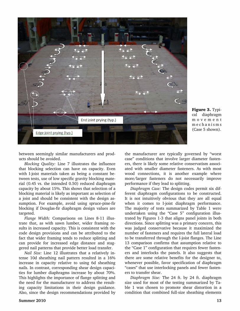
Figure 3 illustrates these trends for a 2009 IBC Table 2306.2.1(1) “Case 5” diaphragm configuration that aligns panel joints in both directions. Shear flow causes panels at the reactions to rotate in opposite directions towards the span centerline. The magni-
tude of this rotation is typically consistent between diaphragm tension and compression chords.
Due to panel geometry, the observed movement between adjacent sheathing panels is typically sev-eral times greater along long edge joints than at short
Summer 2010 11
Figure 1. Typical diaphragm test configuration (24 x 24 ft., Case 5 shown).

end joints. The large relative movement between
panel edges creates a tension perpendicular-to-grain splitting force across the framing at the fasteners for adjacent panels. At panel end joints, it induces per-pendicular-to-grain forces into the framing as panel end joints rotate and the nails induce perpendicular-to-grain prying forces into the framing. Ultimately, these deformations lead to failure in some combina-
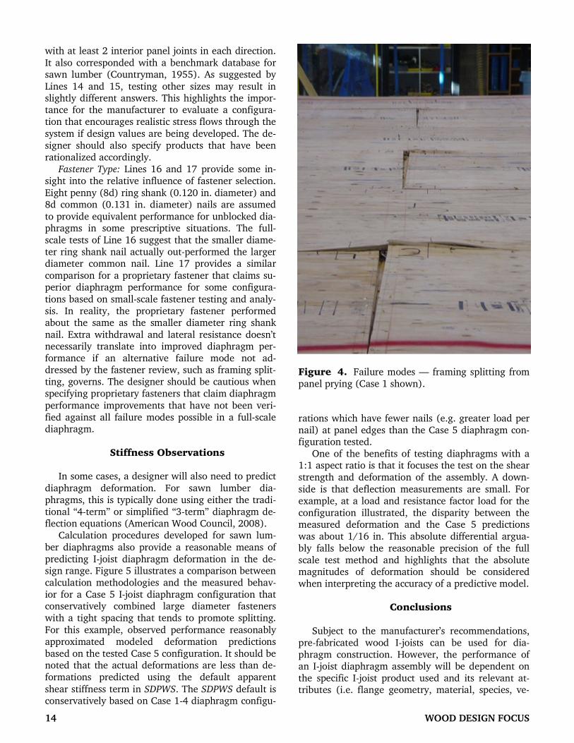
tion of panel buckling/crushing, sheathing nail with-drawal, framing splitting, and/or sheathing edge tear out. The Case 1 diaphragms tested exhibited similar behavior with the exception that panel bearing and crushing were also observed between interlocking panel rows. Figure 4 illustrates the mode of failure observed for a “blocked” Case 1 diaphragm. How-
ever, as with the benchmark sawn lumber tests, the dominant failure modes observed with I-joist dia-phragms were tension perpendicular-to-grain frac-ture of the framing and sheathing nail withdrawal. Sheathing related failure modes played a less signifi-
cant role. Given that many of the potential dia-phragm failure modes that limit capacity are not typi-cally addressed by a connection analysis, the impor-tance of test-based verification for diaphragm sys-tems that depart significantly from the historical ba-sis seems to be confirmed.
Performance Trends
The compiled database of full-scale I-joist dia-phragm tests provides an opportunity to draw com-
parisons between similar test sets. While extrapola-
tions beyond tested conditions should be approached with caution, comparisons in Table 1 suggest trends that could be useful to the designer:
Flange Species: Douglas-fir LVL flanged I-joists out-performed their southern pine counterparts in 4 out of the 5 similar diaphragm configurations tested (Lines 1-5). This trend contradicts what is expected based on a sheathing fastener connection analysis that assumes a higher specific gravity for southern
pine. This trend may be due to the difference in ten-sion perpendicular-to-grain strengths or typical ve-neer thicknesses of the LVL fabricated with each spe-cies. How well these particular commercial species combinations fit the specific gravity-based fastener
design models may also play a role. Regardless, it highlights that an I-joist manufacturer needs to evaluate the diaphragm performance of each primary
species used for flange material. It also suggests that designers should avoid applying the diaphragm rec-ommendations for one I-joist product to another.
LVL Veneer Thickness: The Line 6 comparison illus-trates what a relatively subtle difference in I-joist product composition can have on capacity. Dia-phragms framed with LVL flanges that had the same
species and grade but used a slightly thicker veneer peel had about 15% less capacity. As with the last item, this would seem to confirm that diaphragm per-formance is product dependent. It further emphasizes that extrapolation of performance recommendations
12 WOOD DESIGN FOCUS
Figure 2. Illustration of test setup (24 x 24 ft., Case 5 shown).
between seemingly similar manufacturers and prod-ucts should be avoided.
Blocking Quality: Line 7 illustrates the influence that blocking selection can have on capacity. Even with I-joist materials taken as being a constant be-tween tests, use of low specific gravity blocking mate-rial (0.45 vs. the intended 0.50) reduced diaphragm
capacity by about 15%. This shows that selection of a blocking material is likely as important as selection of
a joist and should be consistent with the design as-sumption. For example, avoid using spruce-pine-fir blocking if Douglas-fir diaphragm design values are targeted.
Flange Width: Comparisons on Lines 8-11 illus-trate that, as with sawn lumber, wider framing re-sults in increased capacity. This is consistent with the code design provisions and can be attributed to the
fact that wider framing tends to reduce splitting and can provide for increased edge distance and stag-gered nail patterns that provide better load transfer.
Nail Size: Line 12 illustrates that a relatively in-tense 10d sheathing nail pattern resulted in a 16% increase in capacity relative to using 6d sheathing nails. In contrast, corresponding shear design capaci-ties for lumber diaphragms increase by about 70%.
This highlights the importance of flange splitting and the need for the manufacturer to address the result-
ing capacity limitations in their design guidance. Also, since the design recommendations provided by
the manufacturer are typically governed by “worst case” conditions that involve larger diameter fasten-ers, there is likely some relative conservatism associ-ated with smaller diameter fasteners. As with most wood connections, it is another example where more/larger fasteners do not necessarily improve
performance if they lead to splitting.
Diaphragm Case: The design codes permit six dif-ferent diaphragm configurations to be constructed.
It is not intuitively obvious that they are all equal when it comes to I-joist diaphragm performance. The majority of tests summarized by Table 1 were undertaken using the “Case 5” configuration illus-trated by Figures 1-3 that aligns panel joints in both
directions. Since splitting was a primary concern, this was judged conservative because it maximized the number of fasteners and requires the full lateral load to be transferred through the I-joist flanges. The Line 13 comparison confirms that assumption relative to the “Case 1” configuration that requires fewer fasten-ers and interlocks the panels. It also suggests that
there are some relative benefits for the designer to, whenever possible, favor specification of diaphragm “cases” that use interlocking panels and fewer fasten-ers to transfer shear.
Diaphragm Size: The 24 ft. by 24 ft. diaphragm size used for most of the testing summarized by Ta-ble 1 was chosen to promote shear distortion in a condition that combined full-size sheathing elements
Summer 2010 13
Figure 3. Typi-cal diaphragm
m o v e m e n t m e c h a n i s m s (Case 5 shown).
with at least 2 interior panel joints in each direction.
It also corresponded with a benchmark database for sawn lumber (Countryman, 1955). As suggested by
Lines 14 and 15, testing other sizes may result in slightly different answers. This highlights the impor-tance for the manufacturer to evaluate a configura-tion that encourages realistic stress flows through the
system if design values are being developed. The de-signer should also specify products that have been rationalized accordingly.
Fastener Type: Lines 16 and 17 provide some in-sight into the relative influence of fastener selection.
Eight penny (8d) ring shank (0.120 in. diameter) and 8d common (0.131 in. diameter) nails are assumed
to provide equivalent performance for unblocked dia-phragms in some prescriptive situations. The full-scale tests of Line 16 suggest that the smaller diame-ter ring shank nail actually out-performed the larger diameter common nail. Line 17 provides a similar
comparison for a proprietary fastener that claims su-perior diaphragm performance for some configura-
tions based on small-scale fastener testing and analy-sis. In reality, the proprietary fastener performed about the same as the smaller diameter ring shank
nail. Extra withdrawal and lateral resistance doesn’t necessarily translate into improved diaphragm per-formance if an alternative failure mode not ad-dressed by the fastener review, such as framing split-ting, governs. The designer should be cautious when specifying proprietary fasteners that claim diaphragm
performance improvements that have not been veri-fied against all failure modes possible in a full-scale diaphragm.
Stiffness Observations
In some cases, a designer will also need to predict
diaphragm deformation. For sawn lumber dia-phragms, this is typically done using either the tradi-tional “4-term” or simplified “3-term” diaphragm de-flection equations (American Wood Council, 2008). Calculation procedures developed for sawn lum-
ber diaphragms also provide a reasonable means of predicting I-joist diaphragm deformation in the de-sign range. Figure 5 illustrates a comparison between calculation methodologies and the measured behav-ior for a Case 5 I-joist diaphragm configuration that conservatively combined large diameter fasteners with a tight spacing that tends to promote splitting.
For this example, observed performance reasonably approximated modeled deformation predictions based on the tested Case 5 configuration. It should be noted that the actual deformations are less than de-formations predicted using the default apparent
shear stiffness term in SDPWS. The SDPWS default is conservatively based on Case 1-4 diaphragm configu-
rations which have fewer nails (e.g. greater load per nail) at panel edges than the Case 5 diaphragm con-figuration tested. One of the benefits of testing diaphragms with a
1:1 aspect ratio is that it focuses the test on the shear strength and deformation of the assembly. A down-
side is that deflection measurements are small. For example, at a load and resistance factor load for the configuration illustrated, the disparity between the measured deformation and the Case 5 predictions was about 1/16 in. This absolute differential argua-
bly falls below the reasonable precision of the full scale test method and highlights that the absolute magnitudes of deformation should be considered when interpreting the accuracy of a predictive model.
Conclusions
Subject to the manufacturer’s recommendations, pre-fabricated wood I-joists can be used for dia-phragm construction. However, the performance of an I-joist diaphragm assembly will be dependent on the specific I-joist product used and its relevant at-tributes (i.e. flange geometry, material, species, ve-
14 WOOD DESIGN FOCUS
Figure 4. Failure modes — framing splitting from panel prying (Case 1 shown).

neer thickness for LVL flanges, etc.). Few I-joists can serve as a direct substitute for sawn-lumber framing in the full range of applications addressed by build-ing code diaphragm design provisions. The manufac-turer’s sheathing nail spacing and diaphragm design recommendations should always be considered as part of the design process.
References APA-The Engineered Wood Association. 2007. TT-
061A: 1-5/16 in. Thick I-Joist Flanges and Dia-
phragm Nail Penetration. Tacoma, WA. American Society for Testing and Materials. 2004.
E455: Standard Test Method for Static Load Testing
of Framed Floor or Roof Diaphragm Constructions
for Buildings. West Conshohocken, PA.
American Wood Council. 2005. National Design Speci-fication for Wood Construction. Washington, DC.
American Wood Council. 2008. Special Design Provi-
sions for Wind and Seismic. Washington, DC.
Countryman, David. 1952. Laboratory Report 55: Lat-eral Tests on Plywood Sheathed Diaphragms. Doug-
las Fir Plywood Association. Tacoma, WA.
Countryman, David. 1955. Laboratory Report 63a: 1954 Horizontal Plywood Diaphragm Tests. Doug-las Fir Plywood Association. Tacoma, WA.
International Code Council. 2009. International
Building Code. International Code Council. Coun-try Club Hills, IL.
International Code Council Evaluation Service. 2010.
AC14: Acceptance Criteria for Pre-Fabricated Wood
I-Joists. Whittier, CA.
Peterson, J. 1983. Bibliography on Lumber and Wood
Panel Diaphragms. Journal of Structural Engineer-
ing. 109(12):2838-2852. Tissell, J.R. and Elliott, J.R. 2004. Report 138: Ply-
wood Diaphragms. APA-The Engineered Wood As-
sociation. Tacoma, WA. Tissell, J.R. 1967. Laboratory Report 106: 1966 Hori-
zontal Plywood Diaphragm Tests. American Ply-wood Association. Tacoma, WA.
Ned Waltz, PE, SECB, Senior Engineer, Product
Evaluation, Weyerhaeuser Company, Boise, ID. Contact
him at [email protected]. J. Daniel Dolan,
P.E., Professor and Director of Codes and Standards,
Composite Materials and Engineering Center, Washing-
ton State University, Pullman, WA. Contact him at
Summer 2010 15
Figure 5. Deflection predictions.