i. friction stir welding and processing of advanced materials · pdf filei. friction stir...
TRANSCRIPT

FY 2005 Progress Report High Strength Weight Reduction Materials
I. Friction Stir Welding and Processing of Advanced Materials
Principal Investigator: Zhili Feng Oak Ridge National Laboratory 1 Bethel Valley Road, Oak Ridge, TN 37831 (865) 576-3797; fax: (865) 574-4928; e-mail: [email protected]
Chief Scientist: James J. Eberhardt (202) 586-9837; fax: (202) 587-2476; e-mail: [email protected] Field Technical Manager: Philip S. Sklad (865) 574-5069; fax:(865) 576-4963; e-mail:[email protected]
Participants: Michael L. Santella, Oak Ridge National Laboratory Tsung-Yu Pan, Ford Motor Company Russell Steel and Scott Packer, MegaStir Technologies Degen, Cassandra, South Dakota School of Mines and Technology M. Kuo and R. S. Bhatnagar, Mittal Steel USA
Contractor: Oak Ridge National Laboratory Contract No.: DE-AC05-00OR22725
Objective • Develop the technological basis for friction stir welding and processing (FSW/P) of advanced high-strength
and lightweight materials for the automotive industry.
• Gain fundamental understanding of the relationships between workpiece and tool material properties during FSW/P.
• Characterize the mechanical properties and microstructures of joints.
• Correlate the proprieties and microstructures produced by FSW/P to the process conditions.
Approach • Conduct experimental welding and processing tests on advanced materials using the state-of-the-art FSW/P
process development system.
• For particular workpiece materials, select the tool material based primarily on high-temperature strength, wear resistance, and chemical compatibility.
• Evaluate mechanical properties and their correlation with microstructures produced by FSW/P.
• Develop predictive modeling capability to study the properties as a function of process conditions.
Accomplishments • Completed a study on friction stir processing to improve properties of cast magnesium alloy AM60B.
• Demonstrated the feasibility of friction stir spot welding of advanced high-strength steels.
• Conducted friction stir processing of steel 1080 for wear resistance improvement.
• Initiated friction stir processing of Ti.
122

High Strength Weight Reduction Materials FY 2005 Progress Report
Future Direction • Investigate the effects of heat treatment on the fatigue life of FSP cast aluminum alloys.
• Develop new approaches for FSSW without the exit hole for improved structural properties of the joint.
• Carry out FSSW of other lightweight materials and dissimilar welds.
• Use transmission electron microscopy to characterize the microstructure improvements to the cast surfaces.
• Assess the ability of FSP to produce rapidly solidified surface microstructures.
Introduction Friction stir welding (FSW) is a novel solid state joining method. The process characteristics and advantages for joining materials that are difficult to join by conventional fusion welding processes were discussed in the previous annual report.
Applications of FSW to aluminum alloys have been a great success. Currently, the technology forefronts are rapidly evolving: there is tremendous interest to extend the technology to welding high-performance and high-melting-temperature materials. Other novel applications of the process are emerging. For example, it can be used to thermomechanically process a material for microstructure refinement and property improvement.
This program aims at advancing FSW/P technology to promote the increased use and adoption of highstrength lightweight materials in automotive structures, particularly heavy vehicles. This supports the goals of the Office of FreedomCAR and Vehicle Technologies to increase fuel efficiency and reduce emissions of heavy trucks by weight reduction without sacrificing strength and functionality.
In FY05, we completed studies on friction stir processing of cast Mg alloy for properties improvement, and friction stir spot welding of advanced high-strength steels. In addition, we initiated studies on friction stir processing of Ti alloys and 1080 steel. This progress report will focus on the first two activities. The progress on Ti and 1080 steel will be reported in future reports when more comprehensive results are available.
Friction Stir Spot Welding of Advanced High-Strength Steels Friction stir spot welding (FSSW), or spot friction welding, is a new process that recently has received
considerable attention from the automotive and other industries [1]. A novel variant of the “linear” friction stir welding (FSW) process, FSSW creates a spot, lap-weld without bulk melting. The appearance of the resulting weld resembles that of a resistance spot weld commonly used for auto-body assembly. The solid-state bonding and other features of the process makes it inherently attractive for body assembly and other similar applications. Today’s primary welding process for auto body structure assembly – the electric resistance spot welding (RSW) process – can be problematic for many new high-performance light weight structural materials such as Al alloys and advanced high-strength steels (AHSS) [2,3].
So far, the majority of the research and development efforts on FSSW have been on aluminum alloys. Because Al alloys are easy to deform at relatively low temperatures (below about 550°C) they are relatively easy to friction stir weld. Indeed, the development of FSSW for Al alloys has been quite successful. Mazda reported the first application of FSSW on its 2003 RX-8, a mass production car. The entire Al rear door was friction stir spot welded [4]. Other auto companies also announced introduction of FSSW to weld Al body parts. The FY04 annual report included our R&D activities on this subject.
Two distinctive variants of the FSSW process have been reported in the open literature [5-8]. The first approach, used by Mazda, employs a fixed pin tool geometry [5,7]. The protruded pin leaves a characteristic exit hole in the middle of the joint. The second approach [8] utilizes delicate relative motions of the pin and the shoulder to refill the pin hole. Based on the information available, the second approach would require relatively long processing time to accommodate the complex motions of the tool to fill the hole. In comparison, the fixed pin approach is very fast. For Al alloys, a weld can be made in less than one second [7]. Also, the welding
123

FY 2005 Progress Report
machine and control system for the fixed pin approach is simple and easy to integrate on a highvolume mass production assembly line. Mazda reported over 90 percent operation energy savings and over 40 percent capital investment reductions when compared to the conventional resistance spot welding of Al alloys.
Today, steel is still the primary material for body structures of high-volume mass-produced cars by all major car makers. The great emphasis on safety and vehicle weight reduction to improve fuel efficiency has been driving the increased use of AHSS in automobile body construction. However, welding AHSS presents some unique technical challenges to both the steel suppliers and the auto end-users. Data available so far have indicated that resistance spot welding of AHSS with the welding practices developed for conventional mild steels may not be the preferred approach to achieve the full benefits of AHSS. The biggest technology barrier inhibiting the use of RSW for AHSS is the profound weld property degradation [2, 9-11]. Due to the extremely high cooling rate in RSW, the weld nugget region of AHSS would develop highly brittle microstructures and is prone to solidification related weld cracks/defects. Such problems tend to be more prominent in higher grade AHSS with relatively high carbon and alloying element contents such as DP1000, Martensitic, and TRIP steels. The shortened electrode life is another major issue for RSW of AHSS because of the chemical reaction between the Zn coating and the copper electrode and high welding force. Alternative welding processes that minimize the weld property degradation without adversely affecting the productivity of body assembling would be extremely important to fully realize the advantages of AHSS in structure safety and fuel efficiency.
Table 1. Steel Chemistry in Wt. percent.
High Strength Weight Reduction Materials
The success of FSSW in Al alloy body structures has led to tremendous interests in applying the technology to weld advanced high strength steels. However, past research and development on linear friction stir welding have shown that steels are much more difficult to friction stir weld than Al alloys [12]. The technical difficulties stem from the very fundamental aspect of the FSW process – compared to aluminum alloys, FSW of AHSS must operate at much higher temperatures and it requires much higher mechanical loading for plunging and stirring. These technical difficulties are also expected for FSSW. The high-volume, high-speed, and costconscious requirements of auto-body assembly lines make the development of FSSW even more challenging.
In FY05, we conducted a feasibility study on FSSW of AHSS. While other forms of FSSW are being evaluated for welding steels and other high melting temperature materials [13], this study was based on the fixed pin approach, mainly because of its simplicity and relatively short welding time. The study was to explore the following: (1) the feasibility of producing FSSW in AHSS in a relatively short period of time acceptable to the industry, (2) the possibility of using existing tool materials for FSSW of AHSS, and (3) the microstructural responses of AHSS to the FSSW process.
Experimental Two types of uncoated AHSS steels were selected for this feasibility study. The first one (DP600) was a dual-phase steel with nominal strength of 600MPa, and the second one (M190) was a martensitic steel with nominal strength of 1310MPa. The thickness of the material was 1.6 mm.
Table 1 provides the chemical composition of the steels.
C Mn P S Si Cu Ni Mo Cr Cb V Ti DP600 0.084 0.94 0.011 0.006 0.313 0.02 <0.01 <0.01 0.02 <0.003 0.004 0.004 M-190 0.168 0.4 0.009 0.005 0.169 0.036 0.013 0.003 0.023 <0.003 <0.003 0.034
124

Plunging Stirring Drawing out
High Strength Weight Reduction Materials
Welding trials were performed on a laboratory friction stir welding research and development system. Figure 1 illustrates the basic process of the fixed pin approach used in this study. The welding cycle begins with a rotating tool with a protruded pin plunging into the upper sheet of the lap joint. The plunge load is supported from the bottom side with a backing plate or anvil to sustain the plunging load. The heat generated by the rotating pin softens the material and facilitates the penetration of the pin. Much more heat is generated to further soften a large region of the material underneath the tool shoulder after the tool shoulder contacts the top surface of the upper sheet. The softened material is pushed and stirred to form the metallurgical bond around the rotating pin. The forge pressure from the tool shoulder also keeps the interface between the two workpieces in intimate contact to facilitate the bonding. The tool is retracted at the end, leaving the characteristic hole in the middle of the weld.
All welds were made under displacement control mode – the tool was plunged into the material to a pre-determined depth. For all the tests conducted in this feasibility study, the tool rotation speed was fixed at 1500 rpm. The total welding time varied from 1.6 sec to 3.2 sec through changes in the plunge rate.
Plunging Stirring Drawing out
Figure 1. Principles of FSSW with fixed pin.
FY 2005 Progress Report
The tool had a tapered pin. It was 2.0-mm long. The shoulder of the tool was 10 mm in diameter.
As in the case of the linear friction stir welding, tool material is expected to be a critical technical issue for FSSW. In this work, the tool was made of polycrystalline cubic boron nitride (PCBN), a material that has been successfully used for linear friction stir welding of steel and other high melting temperature materials [14]. A single tool was used in this study. This single tool made over one hundred welds without any noticeable degradation or wear.
Tensile-shear and cross-tension mechanical testing were performed for selected welding conditions to evaluate the mechanical strength of the joints produced in this work. The tensile shear specimen was 38.1-mm wide and 127-mm long. The crosstension specimen was 50.8-mm wide and 152.4-mm long, with the distance between the loading holes at 101.6 mm. The weld was made at the center of the overlapping (38 mm) region, as shown in Figure 2.
Figure 2. Appearances of the tensile shear and the crosstension welded coupons. The welds were at the center of the overlapping region.
125

FY 2005 Progress Report High Strength Weight Reduction Materials
Results and Discussions of the stirring/mixing of the material between the
Figure 3 shows the overall cross-sectional views of two sheets. The width of the bonding ligament, a
both the M190 weld and DP600 weld made with critical factor determining the strength of the weld,
2.1 sec welding time. A close-up view in the was relatively small in this study. Additional efforts would be needed to further improve the size of bond bonding interface region of the M190 weld is given ligament. in Figure 4. Clearly, metallurgical bonding was
formed between the top and bottom workpieces To evaluate the effects of welding thermal cycle on around the penetrating pin. As in the case of Al alloy welds, the material from the bottom piece was the properties of the welds, variations in the
pushed up by the plunging action of the rotating pin, microhardness were measured across them. Figure 5
causing the workpiece interface to bend upward and shows the microhardness distributions in the top workpiece at three different depths, approximately ¼ form a “hook”. The solid-state phase transformations (0.4mm), ½ (0.8mm), and ¾ (1.2 mm) of the plate that occur in carbon steels during cooling make it thickness, as measured from the top surface. They difficult to directly observe details are labeled as ¼t, ½t, and ¾t in the figure. The location of the exit hole and the periphery of the tool shoulder are also illustrated in the figure to provide the spatial reference for the discussion of the hardness variations.
The martensitic M190 weld shows considerable softening outside the stir zone. The minimum hardness, about 200 Hv, was located about 5-mm away from the weld center, corresponding to the shoulder radius of the tool. However, the hardness in the stir zone was fully recovered back to the 430 Hv base metal level. It is important to point out that the minimum hardness location is quite far away from the bonding region at the interface. The softened region was outside the thermomechanically affected zone (TMAZ) where substantial plastic deformation and material flow occur during the welding process.
Due to the differences in chemistry, DP600 steel showed very different microhardness profiles under the same welding condition. The softening, while still measurable, was relatively insignificant compared to the base metal microhardness level. The softening was mostly outside the shoulder diameter, particularly for the ¼ t and ½ t depth. On the other hand, the stir zone appeared to be hardened. The maximum hardness was about 250 Hv, compared to the base metal average of 210 Hv.
The above variations of the microhardness can be related to the microstructural changes in the different regions of the weld. While more detailed microstructural analyses are still on-going, the results obtained so far from the optical
126
Figure 3. Cross-section of FSSW. Top: M-19; bottom: DP600. Welding time: 2.1 sec.
Figure 4. Close section view of the bonding interface region. M190 Steel, welding time: 2.1 sec.

High Strength Weight Reduction Materials
500 1/4t 1/2t 3/4t
400
300
200
100
0 0 5 10 15 20
Position (mm)
exit hole
Tool shoulder
300
250
200
150
100
50
0 0 5 10 15 20
1/4t 1/2t 3/4t
exit hole
Tool shoulder
Position (mm)
Figure 5. Micro-hardness distribution across the weld in top sheet. Top: M190; bottom: DP600. Welding time: 2.1 sec.
microstructure evaluation are presented below to help understand the hardness changes in the AHSS welds produced by FSSW.
Figures 6 and 7 show, respectively, the microstructures at three selected representative locations in the M190 and DP600 welds. The locations of these metallographic photos are schematically illustrated in Figure 3 by the corresponding labels. Label (a) indicates the base metal region, (b) the transition region exhibiting the
HV,
500
g H
V, 5
00g
FY 2005 Progress Report
reduction of hardness, and (c) the region near the bonding interface which is inside the TMAZ.
The base metal of the martensitic M190 steel has a martensitic microstructure (Figure 6 (a)). In the transition region located near the periphery of the tool shoulder, the material appeared to be heated to a peak temperature between the A1 and A3 temperature – the so-called intercritical region where the ferrite and austenite co-exist at the peak temperature. While the austenite will transform back to martensite on cooling, the ferrite remains. This results in a dual-phase (ferrite + martensite) microstructure in the intercritical region of the weld (Figure 6 (b)). The formation of the ferrite phase hence reduces the hardness from that of the complete martensite microstructure of the base metal. Outside this intercritical region, the material would experience a peak temperature below the A1 temperature. There the metastable martensite microstructure would decompose to a more stable ferrite+Fe3C microstructure, which also would reduce the hardness. In the TMAZ (labeled as (c) in Figure 3), the material would be heated to above the A3 temperature. The material in the TMAZ would therefore be fully austenitized on heating and transformed back to martensite due to the high hardenability of the martensitic steel. Consequently, the hardness of the TMAZ is expected to reach that of the base metal. Because the bonding region is located in the TMAZ, it would exhibit the similar microstructure and hardness of the base metal.
As shown in Figure 7 (a), the base metal of the DP600 steel has a dual-phase microstructure consisting of a ferritic grain matrix and considerable amounts of the hard phase (bainite and/or martensite) islands mostly decorating the boundaries of the ferrite grains. In the transition region (Figure 7 (b)), the hardened phase region undergoes phase transformation to form fine grained structures. The resultant microstructure in this region is a network of fine grained microstructure surrounding the large ferritic grains. As in the case of M190 weld, it is expected that the peak temperature in this region falls within the intercritical temperature range to form a mixture of austenite and ferrite on heating. The austenite then transforms back to hard phases on cooling. The details of these fine grained
127

FY 2005 Progress Report High Strength Weight Reduction Materials
(a)
(b)
(c)
Figure 6. M190, 2.1 sec (a) Base metal, (b) transition BM to intercritical region (on the right side of the photo), (3) TMAZ. The locations are given in Figure 3.
(a)
(b)
(c)
Figure 7. DP600. (a) base metal, (b) Transition from BM to the inter-critical region (on the left side of the photo), (3) TMAZ. The locations are given in Figure 3.
128

High Strength Weight Reduction Materials FY 2005 Progress Report
structures would not be resolved under the optical 12 microscope. In the TMAZ, the material is expected M-190 to be fully austenitized on heating. Due to the 10
relatively high hardenability of DP600 steel, an increased amount of bainite/acicular ferrite was formed on cooling, resulting in the increase in the hardness in TMAZ.
The above results suggest that, for the two advanced high-strength steels studied, the FSSW process was able to maintain, to a great extent, the hardness and the microstructure of the base metal in the bonding interface region. This could be attributed to the combination of moderate cooling rate [13] associated with the FSSW process (compared to RSW) and the relatively high hardendability of
2
0
DP600
2.1 3.2 Weld Time (Second)
Figure 8. Peak loads from tensile shear test.
Peak
Loa
d (k
N)
8
6
4
AHSS. 6
This provides the technical basis for further 5
refinement and optimization of the FSSW process to control or maintain the microstructure and properties in the bonding region of the AHSS weld.
The resulting microstructure in the bonded region also suggests the material flow and bonding takes place when the material is fully austenitized. Such information would be important for the future process and tool material development for FSSW of AHSS.
Figure 8 shows the peak loads measured by the tensile shear test. Each data point represents the average of three samples made under the same welding and material conditions. For both DP600 and M190 steel, an increase in welding time from 2.1 to 3.2 seconds resulted in increases in the peak load strength. This correlated well with the increased bonding ligament width developed in the longer welding time conditions. The cross-tension testing results are presented in Figure 9, for the 3.2 welding time condition.
It should be pointed out that only small bonding ligament widths were obtained in this feasibility study. As the bonding ligament width is a controlling factor for the strength of the joint, it is expected that substantial improvement in joint strength can be achieved if the bonding ligament width can be increased through further process development and modifications to the tool geometry.
1
0
M-190
DP600
3.2 Weld Time (Second)
Figure 9. Peak loads from cross-tension test.
Conclusion This study investigated the feasibility of friction stir spot welding advanced high-strength steel sheet metal for automotive applications. It was found that:
• It is possible to use the fixed pin approach to produce metallurgical bonding for both DP600 dual phase steel and M190 martensitic steel under 3 seconds of welding time.
• The PCBN tool material was capable of producing over a hundred welds without noticeable wear and degradation.
• The bonding region, located in the TMAZ, exhibited similar microstructure and hardness as in the base metal for both steels studied.
• The M190 steel showed considerable softening. However, this softened region is far away from
Peak
Loa
d (k
N)
4
3
2
129

FY 2005 Progress Report
the bonding region where the failure occurred during the mechanical testing.
• The welding process conditions used in this study produced relatively small bonding ligament widths, thereby limiting the tensile strength levels of the joint. It is expected that substantial improvement in joint strength can be achieved if the bonding ligament width can be increased through further process development and modifications to the tool geometry.
Friction Stir Processing AM60B Magnesium Alloy Die Cast Industry statistics show that worldwide shipments of magnesium totaled about 530,000 metric tons in 2003 with about 35% of the total being attributed to die casting. [15]. Due to the ease with which die castings are made, relatively little Mg is used in wrought products. One important industry segment where the interest in Mg die casting use is increasing is automotive. Currently, an average sized 1500 kg vehicle uses only about 5 kg of Mg, but this amount is growing at an annual rate of about 12% [15,16].
Magnesium alloys are being used in automotive applications primarily as substitutes for other lightweight materials including aluminum alloys and polymer-based materials. For manufacturing, Mg alloys have some important advantages over Al alloys. Their latent heat is only about 2/3 that of Al alloys. They have lower solubility for iron when molten and higher fluidity. For die casting processes this means that Mg alloys have shorter cycle times, they are less reactive with steels so casting dies last longer and they can be cast in thinner sections. Magnesium alloys can develop strength-to-weight ratios exceeding those of all other alloys found in automobiles including steels. They also have excellent damping properties which makes them attractive for improving noise-vibration-harshness (NVH) characteristics.
The increased use of Mg die castings for automotive applications is likely to be promoted by welding, joining, and surfacing technologies. Fusion welding of Mg die castings is likely to be problematic owing to their tendency to form excessive gas porosity in weld fusion zones [17,18]. In contrast, friction stir welding appears capable of producing sound joints
High Strength Weight Reduction Materials
with little or no porosity and good mechanical properties [19,20].
Experimental Die cast plates with dimensions of 127 x 25 x 6 mm were made of the AM60B by a cold chamber casting process under protective atmosphere. The plates nominally contained (5.4-6.1) Al + 0.13 Mn wt% and about 5% porosity on average from gas entrapped during casting. For the friction stir trials the surfaces were left in the as-cast condition.
The friction stir processing was conducted on an MTS-ISTIR system in displacement-control mode. The stir tool was made of H13 steel with a shoulder diameter of 8 mm. The pin was cylindrical with a hemispherical tip; its dimensions were 3 mm diameter x 2 mm length. The working surfaces of the stir tool were smooth. Two tool rotation speeds were used: 1250 rpm and 2500 rpm. The translation speed was fixed at 1.7 mm/s throughout the experiments. These conditions were used to make stir passes with lengths of about 100 mm. Some testing and analysis was done using single stir passes. Other plates were processed with 5-6 passes overlapped on intervals of about 2 mm. Overlapping the passes created relatively consistent stir processed volumes on the plates with dimensions of about 1.52 mm x 10 mm x 100 mm.
The room temperature properties of the friction stir processed surfaces were measured by Vickers microhardness testing, and tensile testing. The microhardness measurements were made on metallographically prepared specimens taken to view the surfaces of single stir passes. The indentations were made under a 50 g load in 200 μm x 200 μm arrays extending from the stir zones into the base metal.
The bars with the overlapped passes were used to make tensile specimens. For the tensile specimens, blanks were electrical discharge machined (EDM) from the stir zones using the shape specified in ASTM E8 for rectangular subsized specimens. Slices 2-mm-thick were then EDM cut from both surfaces of the blanks to provide one specimen of base metal and one specimen where the gage section was entirely within the friction stir processed material. The gage dimensions were 1 mm thick x
130

High Strength Weight Reduction Materials FY 2005 Progress Report
6.2 mm wide x 25 mm long. The nominal strain rate for the tensile tests was 1 x 10⁻³/s.
Results and Discussion A cross-sectional view of a single pass surfacing layer made at 2500 rpm is shown in Figure 10. Large pores are visible in the base metal, but none were found in the stir zone. This behavior was typical of stir passes made for both conditions. Also, pores were not found in prior stir passes of specimens where stir passes were overlapped. The microstructure in the stir zone is shown in Figure 11. The stir zone consists primarily of very fine equiaxed grains with size in the range of 5-10 μm. There is no evidence of solidification structure and the material in the stir zone appears to contain only relatively small second phase particles. Examination of this stir zone in a scanning electron microscope (SEM) confirmed that it was largely single-phased. The Mg17Al12 compound which is a major phase in the as-cast material was apparently dissolved in the Mg matrix during the stir processing.
An optical micrograph showing a top surface view of single friction stir pass made at 1250 rpm is shown in Figure 12. The grid used for microhardness measurement is also visible. An image representation of the hardness distribution is shown below the micrograph. The average hardness over 1239 indents in the base AM60B metal was 59.3 ± 8.6 kg/mm2. The average hardness in the stir zone over 861 indents was 71.7 ± 6.7 kg/mm2 which represents an increase of ~ 21% over that in the base metal.
Figure 10. Optical micrograph showing cross section view of single stir pass in AM60B made at 2500 rpm.
Figure 11. Optical micrograph showing microstructure of single stir pass in AM60B made at 2500 rpm.
Figure 12. Optical micrograph showing top view of a friction stir pass on the surface of an AM60B plate. Microhardness distribution is shown on the bottom.
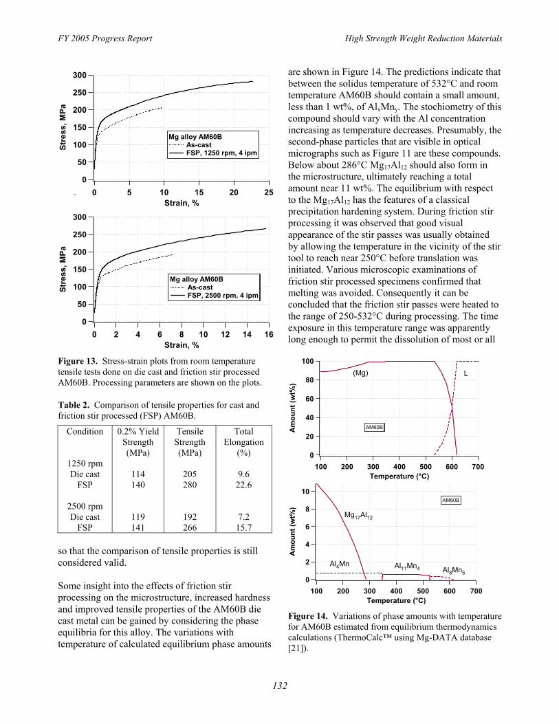
Data comparing the room temperature tensile properties of the AM60B base metal to friction stir processed metal are shown in Figure 13 and Table 2. Duplicate specimens were tested at both tool rotation speeds and the stress-strain plots are representative of the tensile behavior at each speed. Tabulated values are averages of two specimens at each condition. The friction stir processing increased each of the tensile properties over those of the die cast metal. Yield strengths were increased about 18%; tensile strengths were increased about 36%; and, ductility more than doubled. It should be noted that the die cast plates were heated by the friction stir processing. As a consequence, the die cast specimens were subjected to multiple undefined thermal excursions. These unintended heat treatments could influence property values of the cast metal. However, the stir processed material would have been subjected to similar heat treatments
131
FY 2005 Progress Report High Strength Weight Reduction Materials
300 are shown in Figure 14. The predictions indicate that between the solidus temperature of 532°C and room
250 temperature AM60B should contain a small amount,
Stre
ss, M
Pa
Stre
ss, M
Pa
200
150 Mg alloy AM60B
100 As-cast FSP, 1250 rpm, 4 ipm
50
0 0 5 10 15 20 25
Strain, %
300
250
200
150 Mg alloy AM60B
100 As-cast FSP, 2500 rpm, 4 ipm
50
0 0 2 4 6 8 10 12 14 16
Strain, %
less than 1 wt%, of AlxMny. The stochiometry of this compound should vary with the Al concentration increasing as temperature decreases. Presumably, the second-phase particles that are visible in optical micrographs such as Figure 11 are these compounds. Below about 286°C Mg17Al12 should also form in the microstructure, ultimately reaching a total amount near 11 wt%. The equilibrium with respect to the Mg17Al12 has the features of a classicalprecipitation hardening system. During friction stir processing it was observed that good visual appearance of the stir passes was usually obtained by allowing the temperature in the vicinity of the stir tool to reach near 250°C before translation was initiated. Various microscopic examinations of friction stir processed specimens confirmed that melting was avoided. Consequently it can be concluded that the friction stir passes were heated to the range of 250-532°C during processing. The time exposure in this temperature range was apparently long enough to permit the dissolution of most or all
Figure 13. Stress-strain plots from room temperature 100 tensile tests done on die cast and friction stir processed (Mg) L
80AM60B. Processing parameters are shown on the plots.
Am
ount
(wt%
) A
mou
nt (w
t%)
Table 2. Comparison of tensile properties for cast and friction stir processed (FSP) AM60B.
Condition 0.2% Yield Tensile Total Strength Strength Elongation
60
40 AM60B
20
(MPa) (MPa) (%) 0 1250 rpm 100 200 300 400 500 600 700 Die cast 114 205 9.6 Temperature (°C)
FSP 140 280 22.6 10
AM60B2500 rpm Die cast 119 192 7.2
FSP 141 266 15.7 so that the comparison of tensile properties is still
8 Mg17Al12
6
4
considered valid. Some insight into the effects of friction stir processing on the microstructure, increased hardness and improved tensile properties of the AM60B die cast metal can be gained by considering the phase equilibria for this alloy. The variations with temperature of calculated equilibrium phase amounts
2 Al4Mn Al11Mn4 Al8Mn5 0
100 200 300 400 500 600 700 Temperature (°C)
Figure 14. Variations of phase amounts with temperature for AM60B estimated from equilibrium thermodynamics calculations (ThermoCalc™ using Mg-DATA database [21]).
132

High Strength Weight Reduction Materials
of the Mg17Al12 that may have formed in the original cast structure because it was not observed in the stir zones. This observation is in agreement with those from a similar study of thixomolded AM60B [22]. The increased hardness and yield strength in the stir zones can then be attributed to a combination of solid solution hardening by Al in the Mg matrix phase, reprecipitation of Mg17Al12 as fine particles, and refinements to the grain structure. The increases of tensile strength and ductility imply that areal fraction of porosity in the stir zones was lower than that of the as-die-cast metal [23].
Conclusion The ability of friction stir processing to produce stir passes of high integrity on AM60B was demonstrated. Grain structure in the stir zones was largely equiaxed with grain sizes of 5-10 μm. The grains appeared to be all of a single phase and to contain a small amount of second-phase particles. Based on metallographic evidence and thermodynamic considerations the stir zone microstructures were assumed to consist of a Mg matrix, possibly supersaturated with Al, and AlxMny particles. Tensile testing showed that the yield strength in the stir zones was 18% higher than that of die cast metal. Tensile strength in the stir zones was in the range of 36% higher than die cast metal. Friction stir processing doubled the tensile ductility of the AM60B.
Publications Feng Z, Santella M L, David S A, Steel R J, Packer S M, Pan T-Y, Kuo M, and Bhatnagar R, S, (2005), “Friction Stir Spot Welding of Advanced High-Strength Steels - a Feasibility Study”, SAE 2005 Congress, SAE-International, Detroit, MI, Technical Paper No 2005-2001-1248.
Awang M, Mucino V, Feng Z, and David S A, (2005), “Thermo-Mechanical Modeling of Friction Stir Spot Welding (FSSW) Process: Use of an Explicit Adaptive Meshing Scheme”, SAE 2005 Congress, SAE-International, Detroit, MI, Technical Paper No 2005-2001-1251.
Arul S G, Pan T-Y, Pan J, Lin P C, Feng Z, and Santella M L, (2005), “Microstructures and Failure Mechanisms of Spot Friction Welds in Lap-Shear
FY 2005 Progress Report
Specimens of Aluminum 5754 Sheets”, SAE 2005 Congress, Detroit, MI, Technical Paper No 20052001-1256.
Santella M L, Feng Z, Degen C, and Pan T-Y, (2005), “Modifying AM60B Magnesium Alloy Die Cast Surfaces by Friction Stir Processing”, 7th International Conference on Trends in Welding Research, S. A. David (Ed.) TMS, Pine Mountain, GA.
Santella M L, Feng Z, Degen C, and Pan T-Y, (2005), “Friction Stir Processing to Improve the Surface Properties of Aluminum and Magnesium Castings”, Materials Science & Technology 2005 Conference, ASM International, Pittsburgh, PA. Santella, M. L., Engstrom, T., Storjohann, D., and
Pan T.-Y., (2005) “Effects of friction stir processing on mechanical properties of the cast aluminum alloys A319 and A356,”, Scripta Materialia, 53(2), 201-206.
Feng Z, Pan T-Y, Santella M L, and David S A, (2005), “Friction Stir Spot Welding and Its Applications”, AeroMat 2005, ASM International, Orlando, FL.
Woo W, Liaw P K, Choo H, Brown D W, Feng Z, David S A, and Hubbard C R, (2004), “D-41 Two-Dimensional Mapping of Residual Stresses in 6061-T6 Aluminum Friction Stir Welds”, Powder Diffraction, 19:(2), 202.
References 1 Hancock, R., 2004, "Friction welding of
Aluminum Cuts Energy Cost by 99%," Welding Journal, vol. 83, pp. 40.
2 Shi, S.G. and Westgate, S.A., 2003, “Resistance spot welding of high-strength steel sheet,” Corporate Research Program Report No 767/2003, The Welding Institute, Cambridge, UK.
3 Spinella, D. J., Brockenbrough, J. R., and Fridy, J. M., 2005, "Trends in Aluminum Resistance Spot Welding for the Automotive Industry," Welding Journal, 84(1), 34-40.
4 "Mazda Develops World's First Aluminum Joining Technology Using Friction Heat", Mazda News Release, February 27, 2003,
133

FY 2005 Progress Report High Strength Weight Reduction Materials
http://www.mazda.com/publicity/release/20030 17 H. Zhao and T. DebRoy, “Pore Formation 2/0227e.html. during Laser Beam Welding of Die-Cast
5 Iwashita, T. "Method and Apparatus for Magnesium Alloy AM60B – Mechanism and Joining." US Patent 6601751 B2, Aug. 5, 2003. Remedy”, Welding Journal, 80, 204-s-210-s
6 Sakano, R., Murakami, K., Yamashita, K., (2001). Hyoe, T., Fujimoto, M., Inuzuka, M., Nagao, 18 A. K. Dasgupta and J. Mazumder, “Laser Y. and Kashiki, H., 2001, "Development of Welding of AM60 Magnesium Alloy”, Spot FSW Robot System for Automobile Body Magnesium Technology 2004, ed. A. A. Luo, Members," Proc. 3rd International Symposium TMS, pp 43-48. of Friction Stir Welding, Kobe, Japan. 19 N. Li, T.-Y. Pan, R. P. Cooper, D. Q. Houston,
7 Pan, T., Joaquin, A., Wilkosz, D. E., Z. Feng, and M. L. Santella, “Friction Stir Reatherford, L., Nicholson, J. M., Feng, Z., and Welding of Magnesium AM60 Alloy”, Santella, M. L., 2004, "Spot Friction Welding Magnesium Technology 2004, ed. A. A. Luo, for Sheet Aluminum Joining," Proc. 5th TMS, pp 19-23. International Symposium on Friction Stir 20 J. I. Skar, H. Gjestland, L. D. Oosterkamp, and Welding, Metz, France. D. L. Albright, “Friction Stir Welding of
8 Allen, C. D., and Arbegast, W. J., 2005, Magnesium Die Castings,” Magnesium "Evaluation of Friction Stir Spot Welds in 2024 Technology 2004, ed. A. A. Luo, TMS, pp 25-Aluminum," SAE Technical Paper No 2005-01 30 1252, Society of Automotive Engineers. 21 N. Saunders, “Mg-DATA, a database for
9 Ferrasse, S. Verrier, P and Meesemeacker, F, thermodynamic calculations for Mg alloys,” 1998, “Resistance spot weldability of high- Thermotech Ltd., Surrey Technology Centre, strength steels for use in car industry,” Welding The Surrey Research Park, Guilford, Surrey in the World, 41(2), p177-195. GU2 7YG, U.K.
10 Yamazki, K, Sato, K, and Tukunaga, 2000, 22 J. A. Esparza, W. C. Davis, and L. E. Murr, “Static and fatigue strength of spot welded joint “Microstructure-property studies in frictionin ultra-high-strength, cold-rolled steel sheets,” stir-welded, Thixomolded magnesium alloy Welding International, 14(7), p533-541. AM60,” Journal of Materials Science, 38, pp
11 Peterson, W, 1997, “Dilution of weld metal to 941-952 (2003) eliminate interfacial fractures of spot welds in 23 J. P. Weiler, J. T. Wood, R. J. Klassen, E. high and ultra-high strength steels,” Proc. Int. Maire, R. Berkmortel, and G. Wang, Conf Advances in Welding Technology, “Relationship between internal porosity and Columbus, 17-19, Sept, 1997, p331-346. fracture strength of die-cast magnesium
12 Gould, J.E., Lienert, T.J. and Feng, Z., 1998, AM60B alloy”, Materials Science & “Recent developments in friction stir welding,” Engineering A, 395, pp 315-322 (2005) SAE Technical Paper Series 981875
13 “Development of Friction Stir Spot Welding Process,” ORNL Internal Research, 2004.
14 Packer, S. M., Nelson, T. W., Sorensen, C. D., Steel, R., and Matsunaga, M., 2003, "Tool and Equipment Requirements for Friction Stir Welding Ferrous and Other High Melting Temperature Alloys." 4th International Symposium on Friction Stir Welding, Park City, Utah.
15 American Metal Market (http://www.amm.com).
16 K. Johnson, “Magnesium Automotive Applications”, Advance Materials & Processes, 160(6), pp 62-65 (2002).
134