i creep and thermal response of long span...
TRANSCRIPT

i
CREEP AND THERMAL RESPONSE OF LONG SPAN PRESTRESSED
CONCRETE INTEGRAL ABUTMENT BRIDGE
AKILU MUHAMMAD
A thesis submitted in fulfilment of the
requirements for the award of the degree of
Doctor of Philosophy (Civil Engineering)
Faculty of Civil Engineering
Universiti Teknologi Malaysia
AUGUST 2017

iv
ACKNOWLEDGEMENT
My ultimate gratitude goes to Allah the beneficent, the merciful, who I
worship, who I ask for help and who created me a human being of sound mind and
health condition and bestowed on me uncountable bounties. Indeed without His help
I will never be able to accomplish this study. May the peace and blessings of Allah
be with my greatest human benefactor, Prophet Muhammad (S.A.W.) my spiritual
leader and guide in the worship of Allah.
My profound acknowledgement goes to my research supervisor Assoc. Prof.
Dr Redzuan Abdullah. I learnt a lot on Finite Element Modelling from him which
formed the foundation of my research. He helped me with the research concept in
line with my interest area and he sincerely guided me in the entire course of this
research. I also acknowledge my second supervisor Ir. Mohamad Salleh Yassin who
has been helpful especially in the structural design of my bridge model. I benefited
from his wealth of experience in bridge design.
I appreciate the study leave given to me by the Management of Waziri
Ummaru Federal Polytechnic, Birnin-kebbi. I thank the management of Tertiary
Education Tax Fund of the Federal Ministry of Education who provided the
research funds for my overseas training.
My profound appreciation goes to my loving wife, Hadiza and our four kids
who endured the inconvenience of living with me and supporting me while on my
study sojourn at Universiti Teknologi Malaysia.
I sincerely express my sincere appreciation to my mother for her endless
prayers for my success and I sincerely thank my guardian, Late Professor Mahdi

v
Adamu, who did his best in inculcating in me the love for scholarship to doctorate
degree level while I was a high school lever. His moral and financial support in the
course of my studies and from primary school to this level has been the pillar of my
support. May Allah reward him abundantly for his kindness.
In the course of my studies, I received numerous support and encouragement
from my relatives and friends. Prominent among them is Col. Mukhtar Adamu for
his numerous financial assistance and moral support. I also acknowledge support I
received from Abbas Tukur, Prof Hussaini Tukur, Dr. Aisha Adamu, Nasiru Adamu,
Kabiru Yauri, Ummu Tukur, Bashar Tukur, Mansur Tukur, Shehu Tukur, Sani
Balarabe Abubakar, Dr Shehu Muhammad, Dr Aliyu Barau and Dr Aliyu Aminu,
Dr Ibrahim Abdullahi and many others too numerous to mention.

vi
ABSTRACT
Integral Abutment Bridges (IAB) are getting popular due to significant cost
savings in their construction and maintenance. Many countries stipulate the use of
IABs in their new bridge construction projects but mostly the span is limited to 60
m. The limit is set considering the concerns on the long-term performance of IAB
beyond 60 m span due to complexities in its response to long-term material
behaviour, environmental loading and backfill soil conditions. This limitation
necessitates the need for research to adequately predict the long-term behaviour of
IAB particularly those with span beyond 60 m. A parametric study is carried out by
performing non-linear finite element analyses using LUSAS to determine the long-
term behaviour of continuous span prestressed concrete IAB. The parameters
considered are backfill soil type, bridge total length, thermal loading and creep.
Subsoil behind bridge abutment is varied from dense sand, loose sand, stiff clay, to
medium stiff clay. The bridge total lengths of 60 m, 90 m, 120 m, and 150 m, with
pier-to-pier spans of 20 m, 30 m, 40 m and 50 m are considered respectively. Three
dimensional models of IAB are subjected to self-weight, vehicle loading,
prestressing force, temperature load ranging from 20 0C to 36
0C and concrete creep.
The bridge response at 75 year life is examined in terms of deformations and
changes in internal forces in the abutment, prestressed beams and pile foundations.
The long term response of the IAB with different backfill soil types and span lengths
subjected to all possible loadings was successfully quantified. The results revealed
that the variation of the displacement and the internal forces in the abutment and the
bridge beam are within the constructable limit where it is possible to design and
construct the IAB beyond the length of 60 m. Seventy five years creep and
shrinkage loading is found to have significant effect on long term behaviour of the
bridge. It causes maximum loss in prestress force by 27 % resulting in reduced
moment and shear capacity of girder by 557 kNm and 321 kN respectively and
increases the girder deflection by 75 mm (160 %) in 150 m IAB. This also resulted
in incremental abutment deflection 25 mm (575 % rise), abutment moment 5410
kNm (95 %), abutment shear 440 kN (41 %), and girder stress 7.53 N/mm2 (378 %)
in 150 m long IAB. Soil-abutment interaction is found to have predominant effect in
comparison to soil-pile interaction. Bridge length has considerable effect on
magnitude of abutment moment causing 5870 kNm (112 %) incremental moment
with increase in bridge length from 60 m to 150 m in varying subsoil stiffnesses.
Results of the analyses are used in the formulation of long-term response prediction
equations for deflection, moment and shear behavior of IAB abutments. The
empirical equations have proven to be adequate and time efficient means of
predicting deformations and changes in internal forces in the IABs of similar
geometry and configurations.
vii
ABSTRAK
Pembinaan Jambatan Tembok Landas Bersepadu (IAB) semakin popular sekarang
kerana ia memberikan penjimatan kos yang ketara daripada segi pembinaan dan
penyelenggaraan. Banyak negara telah mensyaratkan pembinaan IAB bagi projek
pembinaan jambatan yang baharu, namun panjang jambatan kebanyakannya dihadkan
kepada 60 m sahaja. Pertimbangan untuk menghadkan panjang jambatan ini adalah
berdasarkan kepada ketidaktentuan prestasi bahan konkrit dalam jangka panjang,
ketidaktentuan beban yang terjana daripada persekitaran dan juga ketidaktentuan keadaan
tanah tambun di belakang tembok landas. Kekangan ini menyebabkan perlunya dijalankan
penyelidikan bagi membuat jangkaan kelakunan jangka panjang IAB, terutamanya bagi
panjang keseluruhan yang melebihi 60m. Satu kajian parameter telah dijalankan dengan
kaedah analisis unsur terhingga tidak lelurus menggunakan LUSAS bagi menentukan
kelakunan jangka panjang jambatan IAB yang dibina dengan rasuk konkrit prategasan
selanjar. Parameter yang diambil kira adalah jenis tanah tambun di belakang tembok landas,
panjang keseluruhan jambatan, beban suhu dan rayapan konkrit. Jenis tanah tambun di
belakang tembok landas diubah-ubah iaitu daripada jenis pasir tumpat, pasir gembur, tanah
liat kukuh, kepada tanah liat sederhana kukuh. Panjang keseluruhan jambatan yang
dipertimbangkan adalah 60 m, 90 m, 120 m, dan 150 m dengan jarak antara pier penyokong
adalah masing-masing 20 m, 30 m, 40 m and 50 m. Model tiga dimensi bagi IAB dikenakan
beban berat diri, beban kenderaan, daya prategasan, beban suhu dengan julat daripada 20 0C
kepada 36 0C dan juga rayapan konkrit. Kelakunan jambatan pada umur 75 tahun telah
diperiksa dengan melihat kepada nilai pesongan dan perubahan daya dalaman dalam tembok
landas, dalam rasuk prategasan dan dalam asas cerucuk. Kelakunan jangka panjang IAB
yang berinteraksi dengan pelbagai jenis tanah tambun dan panjang keseluruhan jambatan
yang berbeza-beza di bawah semua jenis beban telah diperolehi dengan jayanya.. Hasil yang
didapati adalah perubahan daya dalaman tembok landas dan rasuk prategasan bagi jambatan
IAB yang melebihi 60m adalah dalam had yang boleh direkabentuk dan boleh dibina. Beban
rayapan dan pengecutan selepas 75 tahun didapati memberi kesan yang besar ke atas
kelakunan jangka panjang jambatan. Ia menyebabkan pengurangan daya prategasan
maksimum sebanyak 27.1 % yang akhirnya mengurangkan kapasiti moment dan daya ricih
rasuk masing-masing sebanyak 557 kNm dan 321 kN serta menambahkan pesongan rasuk
sebanyak 75 mm (160 %) pada IAB 150 m panjang. Ia juga menghasilkan penambahan
pesongan tembok landas sebanyak 25 mm (575 %), momen tembok landas sebanyak 5410
kNm (95 %), ricih tembok landas 440 kN (41 %) dan tegasan rasuk 7.53 N/mm2 (378 %)
pada IAB 150 m panjang. Tinda balas yang besar berlaku antara tanah-tembok landas tetapi
tidak besar pada tanah-cerucuk. Panjang jambatan memberi kesan yang besar ke atas nilai
momen tembok landas yang berinteraksi dengan kekukuhan tanah tambun yang berubah-
ubah, iaitu pertambahan sebanyak 5870 kNm (112 %) apabila panjang jambatan bertambah
daripada 60 m kepada 150 m. Hasil daripada analisis telah diguna untuk menerbitkan rumus
bagi membuat ramalan kelakunan jangka panjang nilai pesongan, momen dan daya ricih
tembok landas IAB. Rumus empirik ini terbukti menjadi kaedah yang memadai dan
menjimatkan masa bagi membuat ramalan pesongan dan perubahan daya dalaman IAB yang
sama bentuk dan ukuran.

viii
TABLE OF CONTENTS
CHAPTER TITLE PAGE
DECLARATION ii
DEDICATION iii
ACKNOWLEDGMENT iv
ABSTRACT vi
ABSTRAK vii
TABLE OF CONTENTS viii
LIST OF TABLES xii
LIST OF FIGURES xvii
LIST OF SYMBOLS xxvi
LIST OF APPENDICES xxxii
1 INTRODUCTION 1
1.1 Background of the study 1
1.2 Overview on Integral Abutment Bridge 6
1.3 Problem Statement 11
1.4 Research Objectives 12
1.5 Scope of Research 12
1.6 Research Methodology 13
1.7 Layout of Thesis 16
2 LITERATURE REVIEW 17
2.1 Introduction 17
2.2 Structure system of IAB and Semi-IAB 18
2.2.1 Paucity of Unified Design Code for IABs 21

ix
2.2.2 Types of Integral Abutments 23
2.3 Soil-structure interaction 25
2.3.1 1.1.1 Winkler Spring Approach 26
2.3.2 1.1.2 Soil-structure Interaction in IAB 28
2.3.2.1 Soil-Pile Interaction 29
2.3.2.2 Ultimate soil resistance (uP ) of
cohesive soils 32
2.3.2.3 Development of p-y curve for
laterally loaded piles in clay 35
2.3.2.4 Ultimate soil resistance ( ultP ) of
cohesionless soils 38
2.3.2.5 Development of p-y curve in laterally
loaded piles in cohensionless Soil 39
2.3.2.6 Abutment-Backfill Interaction 44
2.4 Creep and Shrinkage 53
2.4.1 Creep 53
2.4.2 Shrinkage 57
2.4.3 CEB-FIP Creep and Shrinkage Model (1990) 59
2.4.3.1 Creep Strain Assumptions in CEB-
FIP Code 60
2.4.3.2 Creep Coefficient 61
2.4.3.3 Shrinkage Strain Assumptions in
CEB-FIP Code 63
2.4.4 Viscoelastic Behaviour of Creep 64
2.5 Thermal loading on Bridges 66
2.5.1 Uniform Temperature Change 69
2.5.2 Differential Temperature Change 70
2.5.2.1 Approach 1 71
2.5.2.2 Approach 2 72
2.5.3 Nonlinear Temperature Difference Component 72
2.5.4 Heat Transfer 73
2.6 Effect of creep loading on ultimate moment and shear
capacities of prestressed concrete girders 73

x
2.7 Finite Element Modelling in LUSAS 76
2.7.1 Straight Beam Element (BMS3) 77
2.7.2 Straight Beam Element (BTS3) 78
2.7.3 Thick Shell Element (QTS4) 79
2.8 Prior research works on IABs 80
2.8.1 Investigations on Length Limit of IAB 88
2.8.2 Investigations on Creep Loading 91
2.8.3 Superstructure and Substructure Modelling 95
2.8.4 Prior Research Works as Basis for Present
Research 96
2.9 Research Gap 98
3 RESEARCH METHODOLOGY 101
3.1 Introduction 101
3.2 Bridge Details and Loading 102
3.2.1 Bridge Loading 105
3.2.1.1 Load Combinations 111
3.3 Post-tensioned Tendon Profile and Equivalent Prestressed
Force 113
3.4 Finite Element Model 115
3.4.1 Modelling the Prestressing Force 118
3.4.2 Modelling the Soil-Structure Interaction 122
3.4.3 Abutment-Backfill Interaction 127
3.5 Parametric Study 129
3.6 Model Validation 130
3.6.1 Validation of Response from Live and Dead loads 130
3.6.2 Validation of Modelling of Prestressing Force 131
3.6.3 Thermal Result Validation 141
4 ANALYSIS RESULTS AND THE PROPOSED
EMPIRICAL EQUATIONS 143
4.1 Introduction 143
4.2 Creep and Shrinkage effect on IAB 144

xi
4.2.1 Prestress loss and Reduced Moment and Shear
Capacities of Prestressed girders after 75years 144
4.2.2 Effect of Creep on Superstructure of IABs over 75
years
157
4.2.3 Effect of Creep on Substructure of IABs Over 75
Years
166
4.2.3.1 Effect of creep on deformations in
abutment and piles 167
4.2.3.2 Effect of Creep on Internal Forces in
Abutment and Piles 173
4.2.4 Empirical Equations for predicting response of
IABs under creep loading 186
4.2.4.1 Deflection 186
4.2.4.2 Moment 191
4.2.4.3 Shear 194
4.3 Thermal analysis and results 197
4.3.1 Response of Substructure to Thermal Loading 198
4.3.1.1 Abutment and pile deflection 198
4.3.1.2 Abutment moments 205
4.3.1.3 Abutment shears 215
4.3.2 Response of Superstructure to Thermal Loading 222
4.3.2.1 Deflection in Superstructure 222
4.3.2.2 Internal forces in Superstructure 225
5 CONCLUSION AND RECOMMENDATION
5.1 Introduction 228
5.2 Summary of Findings 228
5.2.1 Creep and Shrinkage loading 229
5.2.2 Thermal loading 232
5.3 Conclusion 236
5.4 Recommendation 237
REFRENCES 238
Appendices A-B 250-252
xii
LIST OF TABLES
TABLE NO TITLE PAGE
1.1 Number of IAJB designed and built since 1995 and in-
service in U.S. 9
2.1 Summary of selected criteria used by European countries 22
2.2 Maximum allowable limits for IABs in US 23
2.3 Approximate magnitude of movement required to reach
minimum active and maximum passive earth pressure
condition
38
2.4 Properties for sandy soil (Bowles, 1996) 41
2.5 Approximate magnitude of movement required to reach
minimum active and maximum passive earth pressure
condition (Clough and Duncan 1991) 48
2.6 Characteristic of linear thick beam Element used (LUSAS,
2008b) 77
2.7 Characteristics of nonlinear thick beam Element used
(LUSAS, 2008b) 78
2.8 Characteristic of nonlinear thick shell Element used
(LUSAS, 2008b) 79
3.1 Geometric properties of the structural members of IAB
model 105
3.2 Summary of total dead load per span (50 m) 105
3.3 Summary of total live loads per span (50 m) 106
3.4 Summary of loads on girder (50 m) 106
3.5 Summary of total dead load per span (40 m) 107

xiii
3.6 Summary of total live loads per span (40 m) 107
3.7 Summary of loads on girder (40 m) 108
3.8 Summary of total dead load per span (30 m) 108
3.9 Summary of total live loads per span (30 m) 109
3.10 Summary of loads on girder (30 m) 110
3.11 Summary of total dead load per span (20 m) 110
3.12 Summary of total live loads per span (20 m) 111
3.13 Summary of loads on girder (20 m) 111
3.14 Prestress forces generated in 90 m IAB girders 120
3.15 Prestress definition to BS5400 121
3.16 Material properties of bridge girders 121
3.17 Calculated spring constant for cohesive soils 123
3.18 Spring constants for cohesionless soils 125
3.19 Calculated spring constant for backfill using soil properties
in Bowles (1996) and Michael (2001). 129
3.20 Comparison between FEA and Moment Distribution result 131
4.1 Loss in prestress force over 75years for 20 m spans (60m
IAB) with 4000 kN initial prestress force 145
4.2 Loss in prestress force over 75years for 30 m spans (90 m
IAB) with 4250 kN initial prestress force 145
4.3 Loss in prestress force over 75years for 40 m spans (120 m
IAB) with 4500 kN initial prestress force 146
4.4 Loss in prestress force over 75years for 50 m spans (150 m
IAB) with 5000 kN initial prestress force 146
4.5 Reduction in ultimate moment capacity of 20 m spans (60
m IAB) girder over 75 years 148
4.6 Reduction in ultimate moment capacity of 30 m spans (90
m IAB) girder over 75 years 148
4.7 Reduction in ultimate moment capacity of 40 m spans (120
m IAB) girder over 75 years 149
4.8 Reduction in ultimate moment capacity of 50 m spans (150
m IAB) girder over 75 years 149
4.9 Summary of applied moments and reduction in ultimate 150

xiv
moment capacity for all lengths of IAB girders over 75
years
4.10 Calculated (boldened) and Projected results by
interpolation of reduction in ultimate moment capacity for
all spans of IAB girders over 75 years 151
4.11 Reduction in ultimate shear capacity in 20 m spans (60 m
IAB) girder over 75 years 153
4.12 Reduction in ultimate shear capacity in 30 m spans (90 m
IAB) girder over 75 years 153
4.13 Reduction in ultimate shear capacity in 40 m span (120 m
IAB) girder over 75 years 154
4.14 Reduction in ultimate shear capacity in 50m span (150 m
IAB) girder over 75 years 154
4.15 Summary of applied shear and reduction in ultimate shear
capacity for all lengths of IAB girders over 75 years 155
4.16 Actual and Projected results of reduction in ultimate shear
capacity for all spans of IAB girders over 75 years 155
4.17 Effect of creep on girder and slab deflection in IAB
supported by different subsoil type 160
4.18 Summary of maximum mid-span girder stress on top
surface of slab due to 75 years creep and shrinkage loading 165
4.19 Maximum Increment in lateral deflection at top of
abutment due to 75years creep and shrinkage loading 172
4.20 Peak values of deflection at top of abutment for IABs of
varying lengths supported on substructure soils of varying
stiffness 173
4.21 Increment in abutment moment due to 75years creep and
shrinkage loading in dense sandy soil 178
4.22 Peak values of abutment moment in varying substructure
soils 178
4.23 Maximum increment in abutment shear due to creep and
shrinkage 181
4.24 Peak values of abutment shear in varying substructure soils 181

xv
and IAB lengths
4.25 Summary of deflection at top of abutment due to thermal
load increment 202
4.26 Peak values of deflection due to thermal increment at top of
abutment for IABs of varying lengths and supported on
substructure soils of varying stiffness 203
4.27 Summary of deflection at top of abutment due to
decremental thermal loading 204
4.28 Peak values of deflection due to thermal decrement at top
of abutment for IABs of varying lengths and supported on
substructure soils of varying stiffness 204
4.29 Peak values of abutment moment due to thermal load
increment in IABs of varying lengths and supported by
subsoil of varying stiffness 213
4.30 Peak values of abutment moment due to thermal load
decrement in IABs of varying lengths and supported by
subsoil of varying stiffness 213
4.31 Peak values of abutment shears due to thermal load
increment in IABs of varying lengths and supported by
subsoil of varying stiffness
221
4.32 Peak values of abutment shears due to thermal load
decrement in IABs of varying lengths and supported by
subsoil of varying stiffness
222
4.33 Effect of temperature increment on mid-span girder
deflection in IAB supported by different subsoil type. 223
4.34 Effect of temperature decrement on mid-span girder
deflection in IAB supported by different subsoil type. 224
4.35 Effect of temperature increment on girder and slab moment
in IAB 226
4.36 Effect of temperature decrement on girder and slab moment
in IAB 226
4.37 Effect of temperature increment on girder and slab shears in
IAB 227

xvi
4.38 Effect of temperature decrement on girder and slab shears
in IAB 227

xvii
LIST OF FIGURES
FIGURE NO. TITLE PAGE
1.1 Scheme of a Jointed Bridge 2
1.2 Expansion joint failures 3
1.3 Dangerous expansion joint failures 3
1.4 Dangerous expansion joint failures 4
1.5 Corrosion of bridge bearing 4
1.6 Scheme of an Integral Abutment Bridge 5
1.7 Comparison of bridge construction costs 8
1.8 Rise of IABs in the United States 8
1.9 Summary of bridge type by dates in United Kingdom 9
1.10 Flowchart of research methodology 15
2.1 (a) Jointed Bridge and (b) Integral Abutments 18
2.2 Semi-integral bridge abutment girder-connection 19
2.3 Bridge definitions by Swiss Federal Roads office 20
2.4 Types of IABs 24
2.5 Discontinuity of soil deformation in Winkler spring model 26
2.6 (a) Winker foundation (b) Actual foundation 27
2.7 Arbitrary loading on an elastically supported beam 28
2.8 Three-Dimensional Soil-Pile Interaction 30
2.9 Soil-pile interaction model 31
2.10 Linear approximation of nonlinear yp curve 32
2.11 Effect of wedge action on ultimate soil resistance 33
2.12 Backfill and embankment pressure distribution on the
abutment and the foundation 34
2.13 P-Y curve for saturated soft clay (Matlock 1970) in (Suhail,
2012) 35

xviii
2.14 P-Y curve for stiff clay with no free water (Welch and Reese
1972) in (Suhail, 2012) 37
2.15 P-Y curves for static and cyclic lateral loading in sand 40
2.16 Non-dimensional coefficient for soil resistance versus depth 42
2.17 Values of coefficients Ac and As 42
2.18 Segments of a typical P-Y curve for sandy soil 44
2.19 Relationship between wall movement and earth pressure for
(a) dense and loose sand (b) medium sandy soil 47
2.20 Relationship between wall movement and earth pressure for
(a) dense and loose sand (b) medium sandy soil 49
2.21 Relationship between wall movement and earth pressure 50
2.22 Secant Young’s modulus for granular soil, for sG =2.65 52
2.23 Concrete Strain components under sustained load 55
2.24 Recoverable and irrecoverable concrete creep components 56
2.25 Relationship between shrinkage and creep in freshly laid
concrete 57
2.26 Shrinkage and creep effects in Integral Abutment Bridges:
(a) differential shrinkage effects for composite concrete
bridges (b) creep effects for composite prestressed concrete
bridges 58
2.27 Viscoelastic Behaviour 65
2.28 Stress relaxation 65
2.29 Thermal loading on bridge 67
2.30 Effect of positive thermal gradient on bridge deck 67
2.31 Constituent components of a temperature profile 68
2.32 Correlation between minimum/maximum shade air
temperature (Tmin/Tmax) and minimum/maximum uniform
bridge temperature component (Te.min/Te.max) 70
2.33 Recommended values of linear temperature difference
component for different types of bridge decks for road, foot
and railway bridges 71
2.34 Temperature differences for concrete bridge decks according
to approach 2 72

xix
2.35 Interrelationship between causes and effects in prestress loss 75
2.36 Short and long term loss in prestress force 75
2.37 IAB simplified model showing linear springs 81
2.38 Two dimensional IAB model (b) Three dimensional IAB
model 83
2.39 Finite Element continuum model of steel pile embedded in
sand (a) pile and abutment (b) Pile without abutment 84
2.40 2D model 3D IAB model 85
2.41 Three dimensional finite element model of Rochester Bridge 86
2.42 (a) Cross-sectional view of nodes and elements for FE
modelling of concrete slab on steel girder (b) Bridge
superstructure-abutment connection detail 87
3.1 Prestressed concrete JKR girders 103
3.2 (a) Section of IAB model showing girders, piers and piles.
(b) Girder abutment integral connection 104
3.3 Bending Moments (in kNm) obtained from various load
combinations for 120 m IAB 112
3.4 Parabolic cable profile. 114
3.5 Profile of prestressing cable for three spans 115
3.6 Twenty one piles supporting bridge abutment in three rows
of seven piles in the FE model 116
3.7 FE model of symmetrical half of the 150 m IAB 117
3.8 FE model on IAB deck showing fixity in x axis at extreme
right end of bridge deck to achieve symmetry in y and z
axes. 118
3.9 Beam and Tendon model 119
3.10 Finite element model of the segment showing vertical
applied load and prestressed force application on beam from
profiled tendon symmetrical half of. (a) 150 m girder and (b)
150 m IAB 119
3.11 P-Y curve for soft clay developed for this research 122
3.12 P-Y curve for stiff clay developed this research 123
3.13 P-Y curve for dense sandy soil 124

xx
3.14 P-Y curve for medium dense sandy soil 124
3.15 P-Y curve for loose sandy soil 125
3.16 FE models of 90 m IAB showing sandy backfill of linearly
varying soil stiffness supported by clay soil of uniform
stiffness (b) details of sandy soil on clay soil model. 126
3.17 Relationship between wall movement and earth pressure 128
3.18 Single span IAB 131
3.19 Bending moment diagram for single span IAB 131
3.20 Simply supported restressed concrete beam 132
3.21 FE line model showing deflection due self and imposed load 133
3.22 FE line model showing deflection due to prestress force with
short-term losses. 137
3.23 FE line model showing deflection due to applied load and
short-term prestress force. 138
3.24 FE line model showing axial expansion due to uniform
thermal loading on bridge girder. 141
3.25 FE line model showing deflection due to applied load and
one year creep loading on post-tensioned girder. 141
4.1 Rate of loss of loss in prestress force due to creep 147
4.2 Calculated and projected rate of loss in moment capacities in
60 m to 150 m IAB lengths due to 75 years creep and
shrinkage 152
4.3 Actual and projected rate of loss in shear capacities in 60 m
to 150 m IAB lengths due to 75 years creep and shrinkage. 157
4.4 Vertical deflection on bridge girder (in mm) due to (a)
instantaneous loading alone (b) instantaneous and 75years
creep loading. 158
4.5 Variation in mid-span girder deflection over 75 years in 60
m IAB 161
4.5 Variation in mid-span girder deflection over 75 years in 60
m IAB. 161
4.6 Variation in mid-span girder deflection over 75 years in 90 161

xxi
m IAB
4.7 Variation in mid-span girder deflection over 75 years in 120
m IAB 162
4.8 Variation in mid-span girder deflection over 75 years in 150
m IAB. 162
4.9 Principal stress on top of 150 m IAB deck (N/mm2) (a) after
75years of creep loading (b) without creep loading. 164
4.10
Variation in abutment and pile deflection due to 75 years
creep and shrinkage loading in 60 m IAB in varied
foundation soils 168
4.11 Variation in abutment deflection due to 75years creep and
shrinkage loading in 60 m IAB in varied foundation soils. 168
4.12 Variation in abutment and pile deflection due to 75years
creep and shrinkage loading in 90 m IAB in varied
foundation soils 169
4.13 Variation in abutment deflection due to 75years creep and
shrinkage loading in 90 m IAB in varied foundation soils 169
4.14 Variation in abutment and pile deflection due to 75years
creep and shrinkage loading in 120 m IAB in varied
foundation soils 170
4.15 Variation in abutment deflection due to 75years creep and
shrinkage loading in 120 m IAB in varied foundation soils 170
4.16 Variation in abutment and pile deflection due to 75years
creep and shrinkage loading in 150 m IAB in varied
foundation soils 171
4.17 Variation in abutment deflection due to 75years creep and
shrinkage loading in150 IAB in varied foundation soils. 171
4.18 Variation in top and bottom abutment moment (in N/mm)
for (a) under creep load and (b) under no creep load in 60 m
IAB in dense sandy soil. 174
4.19 Variation in abutment moment due to 75years creep and
shrinkage loading in 60 m IAB under varied foundation 175
xxii
soils.
4.20 Variation in abutment moment (in N/mm) for (a) due to
creep and (b) under no creep load in 90 m IAB supported in
dense sandy soil. 175
4.21 Variation in abutment moment due to 75years creep and
shrinkage loading in 90 m IAB under varied foundation
soils. 176
4.22 Variation in abutment moment (in N/mm) for (a) due to
creep and (b) under no creep load in 120 m IAB supported
in dense sandy soil. 176
4.23 Variation in abutment moment due to 75years creep and
shrinkage loading in 120 m IAB under varied foundation
soils. 177
4.24 Variation in abutment moment (in N/mm) for (a) due to
creep and (b) under no creep load in 150 m IAB supported
in dense sandy soil. 177
4.25 Variation in abutment moment due to 75years creep and
shrinkage loading in 150 m IAB under varied foundation
soils. 178
4.26 Variation in abutment shear (in N) (a) under creep load and
(b) under no creep load in 60 m IAB supported in dense
sandy soil. 182
4.27 Variation in abutment shear (in N) due to 75years creep and
shrinkage loading in 60 m IAB under varied foundation
soils 182
4.28 Variation in abutment shear (in N) due to (a) creep load and
(b) due to no creep load in 90 m IAB supported on dense
sandy soil 183
4.29 Variation in abutment shear (in N) due to 75years creep and
shrinkage loading in 90 m IAB under varied foundation
soils 183
4.30 Variation in abutment shear (in N) due to (a) creep load and
(b) due to no creep load in 120 m IAB supported on dense 184
xxiii
sandy soil
4.31 Variation in abutment shear due to 75years creep and
shrinkage loading in 120 m IAB under varied foundation
soils. 184
4.32 Variation in abutment shear (in N) (a) due to creep load and
(b) without creep load in 150 m IAB supported by dense
sandy soil. 185
4.33 Variation in abutment and Pile shear due to 75years creep
and shrinkage loading in 150 m IAB under varied
foundation soils 185
4.34 Trend line of 75 years creep and shrinkage deflection on
abutment 188
4.35 Comparative values of validated and actual results of
abutment deflection after 75 years creep and shrinkage
loading 190
4.36 Trend line of 75 years creep and shrinkage moment on
abutment 192
4.37 Comparative values of validated and actual results of
abutment moments after 75 years creep and shrinkage
loading 193
4.38 Trend line of 75 years creep and shrinkage shear on
abutment 195
4.39 Comparative values of validated and actual results of
abutment shears after 75 years creep and shrinkage loading 196
4.40 Abutment and pile deflection due to uniform thermal
decrement in 60 m IAB 199
4.41 Abutment and pile deflection due to uniform thermal
increment in 60 m IAB 199
4.42 Abutment and pile deflection due to uniform thermal
decrement in 90 m IAB. 200
4.43 Abutment and pile deflection due to uniform thermal
increment and decrement in 90 m IAB. 200

xxiv
4.44 Abutment and pile deflection due to uniform thermal
decrement in 120 m IAB. 201
4.45 Abutment and pile deflection due to uniform thermal
increment in 120 m IAB. 201
4.46 Abutment and pile deflection due to uniform thermal
decrement in 150 m IAB. 202
4.47 Abutment moment due to uniform thermal decrement in
60 m IAB. 207
4.48 Abutment moment due to uniform thermal increment in
60 m IAB 207
4.49 Variation in abutment moment (in Nmm) due to (a) thermal
load decrement (b) no thermal load and (c) thermal load
increment in 60 m IAB supported on dense sandy soil. 208
4.50 Abutment moment due to uniform thermal decrement in
90 m IAB. 208
4.51 Abutment moment due to uniform thermal increment in
90 m IAB. 209
4.52 Variation in abutment moment (in Nmm) due to (a) thermal
load decrement (b) no thermal load and (c) thermal load
increment in 90 m IAB supported on dense sandy soil. 209
4.53 Abutment moment due to uniform thermal decrement in
120 m IAB 210
4.54 Abutment moment due to uniform thermal increment in 120
m IAB 210
4.55 Variation in abutment moment (in Nmm) due to (a) thermal
load decrement (b) no thermal load and (c) thermal load
increment in 120 m IAB supported on dense sandy soil
211
4.56 Abutment moment due to uniform thermal decrement in
150 m IAB 211
4.57 Abutment moment due to uniform thermal increment in
150 m IAB. 212
4.58 Variation in abutment moment (in Nmm) due to (a) thermal
load decrement (b) no thermal load and (c) thermal load 212

xxv
increment in 150 m IAB supported on dense sandy soil.
4.59 Abutment shears due to uniform thermal decrement in 60 m
IAB supported by soil of varying stiffness 215
4.60 Abutment shears due to uniform thermal increment in 60 m
IAB 216
4.61 Variation in abutment shear (in N) due to (a) thermal load
decrement (b) no thermal load and (c) thermal load
increment in 60 m IAB supported on dense sandy soil.
216
4.62 Abutment shears due to uniform thermal decrement in 90 m
IAB. 217
4.63 Abutment shears due to uniform thermal increment in 90 m
IAB 217
4.64 Variation in abutment shear (in N) due to (a) thermal load
decrement (b) no thermal load and (c) thermal load
increment in 90 m IAB supported on dense sandy soil. 218
4.65 Abutment shears due to uniform thermal decrement and
decrement in 120 m IAB. 218
4.66 Abutment shears due to uniform thermal increment in 120 m
IAB 219
4.67 Variation in abutment shear (in N) due to (a) thermal load
decrement (b) no thermal load and (c) thermal load
increment in 120 m IAB supported on dense sandy soil. 219
4.68 Abutment shears and pile shears due to uniform thermal
decrement in 150 m IAB 220
4.69 Abutment shears and pile shears due to uniform thermal
increment in 150 m IAB 220
4.70 Variation in abutment shear (in N) due to (a) thermal load
decrement (b) no thermal load and (c) thermal load
increment in 150 m IAB supported on dense sandy soil. 221

xxvi
LIST OF SYMBOLS
q - Reaction forces of foundation
w - deflection of the beam on elastic foundation
k - Modulus of subgrade reaction
p - Lateral soil resistance per unit length of pile
y - Lateral deflection of soil per unit length of pile
sE - Soil modulus
uP - Ultimate value of resistance of soil per unit length of pile.
- Unit weight of soil
tZ - Wedge depth of soil
uC - Undrained shear strength of clay
z - Depth of soil from ground level
ultP - Ultimate soil resistance in cohesive soil
0K - Coefficient of earth pressure at rest
aK - Minimum coefficient of active earth pressure
- Angle of wedge action along the horizontal direction
a - Angle of wedge action along the vertical direction
e - Void ratio of soil
'p - Mean confining stress less pore water pressure in the soil
atmp - Atmospheric pressure
- Shear strain of soil
d - Dry density of soil
sG - Specific gravity of soil
w - Density of water
xxvii
- Distance moved by backfill due to abutment push
H - Height of the abutment
horzk - Horizontal soil stiffness
t - Time
)(tcr - Creep strain
)(tsh - Drying or shrinkage strain.
)(t - Uncracked and uniaxially loaded concrete strain.
)(te - Instantaneous strain
)(tsh - Shrinkage strain
)(tT - Temperature strain
0c - Concrete strain components under sustained compressive
stress
0 - initial time
d - Early shrinkage strain
0 - Instantaneous increase in strain.
1 - Time when instantaneous stress is removed
)(. tdcr - Recoverable strain or delayed elastic strain
)(. tficr - The first part is recoverable strain
)(. tfbcr - Basic flow component of second part of recoverable strain
)(. tfdcr - Drying component of second part of recoverable strain
)(. tfcr - Irrecoverable part of the creep strain is called flow
sP - Axial force due to differential shrinkage
- Unrestrained differential shrinkage
slE - Elastic modulus of slab
- Elastic modulus of beam
- Cross sectional area of slab
- Cross sectional area of beam
s
bE
sA
bA
xxviii
sM - Shrinkage moment
- Horizontal shear force
se - Distance from top of beam to center of slab
y - Distance from beam neutral axis to top of beam
c
- Compressive strength
-
Initial strain at loading
- Creep strain at time
- Shrinkage strain
- Thermal strain
- Stress dependent strain
- Stress independent strain
),( 0ttJ - Creep function or creep compliance
)( 0tEc - Modulus of elasticity at the time of loading
cct - Coefficient that depends on the age of concrete
0 - Notional creep coefficient
c - Coefficient to describe the development of creep with time
after loading.
0t - Age of the concrete at loading
- Notional size of the concrete member
- Area of concrete cross section
- Length of the perimeter of the concrete section
- mean concrete compressive strength
- Relative humidity of the ambient environment (%)
)(ia - Creep compliance coefficients which is dependent on age of
loading
G - Linear spring of stiffness
sP
)( 0tci
)(tcc0tt
)(tcs
)(tcT
)(tc
)(tcn
h
cA
u
cmf
RH

xxix
- Coefficient to describe the development of shrinkage with
time
st - Age of concrete at the beginning of shrinkage
-
Incremental non-mechanical strain
MheatT - Linear temperature difference component with for warmer
top cooler bottom
McoolT - Linear temperature difference component for cooler top
warmer bottom
ET - Nonlinear temperature difference component
qz - Internal heat generated in the concrete
- Density of concrete
c - Specific heat capacity of concrete
T - Temperature
ck - Thermal conductivity of concrete
-
Design effective prestress in tendon after all losses
psf - Calculated stress in prestressing steel at section considered
and loading considered
- Characteristic strength of tendon
uM - Ultimate moment capacity of prestressed concrete girders
- Maximum compressive strain of concrete
- Characteristic strength of concrete
- Material factor of safety of concrete
C - Compressional force in concrete
T - Tensional force in concrete
pbf - Design tensile stress in tendons at beam failure
-
Ultimate strain in tendon at failure
-
Area of prestressing steel
s
m
pef
puf
u
cuf
m
pb
psA

xxx
- Effective depth of prestressed beam to centroid of tendons
- Effective width of concrete beam
-
Ultimate strain in tendon
- Effective prestrain in concrete
-
Strain in tendon due to flexure
- Effective prestrain in tendon
- Depth of neutral axis
iP - Prestress force
psE - Modulus of elasticity of tendon
xxI - Moment of inertia of girder
e - Eccentricity of cable from neutral axis of girder
cA - Area of concrete girder
cE - Modulus of elasticity of concrete
- Reduction factor for long term prestress loss
coV - Ultimate shear resistance of prestressed concrete section
tf - Allowable principal stress
- Breadth of section or width of web for T, L and I sections
oM - Moment that produces zero stress at extreme tension fiber.
ptf - Level of prestress in concrete at tensile face.
- designed concrete shear stress
M - Bending moment due to applied load
- Shear force due to applied load
cpf - Design stress at the end of prestress development length
pl - Prestress development length
- Average shear strain of soil
- Angle of internal friction
d
b
pb
ce
p
pe
x
vb
cv
V

xxxi
uy - Ultimate soil deflection
up - Ultimate soil resistance
uC - Undrained cohesion of soil
50y - Half of deflection of soil at ultimate soil resistance
50 - Strain corresponding to one-half the maximum deviator
stresses in an undrained test
a - Nodal displacement
psr - Radius of curvature
- Duct friction coefficient
- Moment due to self-weight of beam
sh - Shrinkage of concrete per unit length for outdoor exposure
cf - Stress at centroid of prestressing steel
K - Unintentional angular displacement for internal tendons
- Tendon force at a distance from the beginning of the curve
- Tendon force at end of the curve
if - Initial stress at jacking
-
Characteristic strength of strand
iM
xP
ieP
stf

xxxii
LIST OF APPENDICES
APPENDIX TITLE PAGE
A Moment Distribution Calculation 250
B Bridge Load Calculations 252

1
CHAPTER 1
INTRODUCTION
1.2 Background of the Study
Bridges have been part of any country’s infrastructural development. They
connect road and rail networks with overpass over obstacles like large bodies of
water, valleys, or existing roads. Their desirable characteristics include structural
stability and durability, simplicity of construction, minimal maintenance, smooth
riding surface, water tightness and aesthetics. Single or multi-span bridges are
usually constructed with expansion joints to accommodate expansion and
contraction of superstructure due to volumetric strains caused by thermal, creep and
shrinkage stresses. Strains from temperature load can lead to cracks development on
concrete which can result in early deterioration of concrete components. Expansion
joints are therefore provided in jointed bridges to accommodate thermal expansions
and contractions; bearings are also provided to accommodate superstructure
movement arising from live loads as shown in Figure 1.1.

2
Figure 1.1 Scheme of a Jointed Bridge
Expansion joints come with their maintenance problems. They are costly to
purchase and install and they wear with time from vehicular traction and
environmental effects (Figures 1.2, 1.3, 1.4). This can result in rough driving
surface, ingress of rain water and de-icing salts, freezing and thawing of trapped
water in joints, leaking of joints and corrosion of reinforced concrete and bearings
(Figure 1.5). Expansion joints and bearings were realised to be the major source of
bridge maintenance problems; extensive and expensive replacement works that
usually consumes a greater portion of bridge maintenance budget are carried out to
repair faulty joints and bearings (Wolde-Tinsae et al., 1988; Mistry, 2005; Sophia et
al., 2006). Leaking joints account for 70 % of defects occurring at ends of girders,
piers and abutment seats (Rodolf and Samer, 2005). Maintenance of expansion
joints and bearings, in many instances, result in disruption of traffic movement and
intra and inter city economic activities.

3
Figure 1.2 Expansion joint failures (BadwaterJournal.com, 2011)
Figure 1.3 Dangerous expansion joint failures (Emseal Infrastructure & Civil
Products, 2014)
4
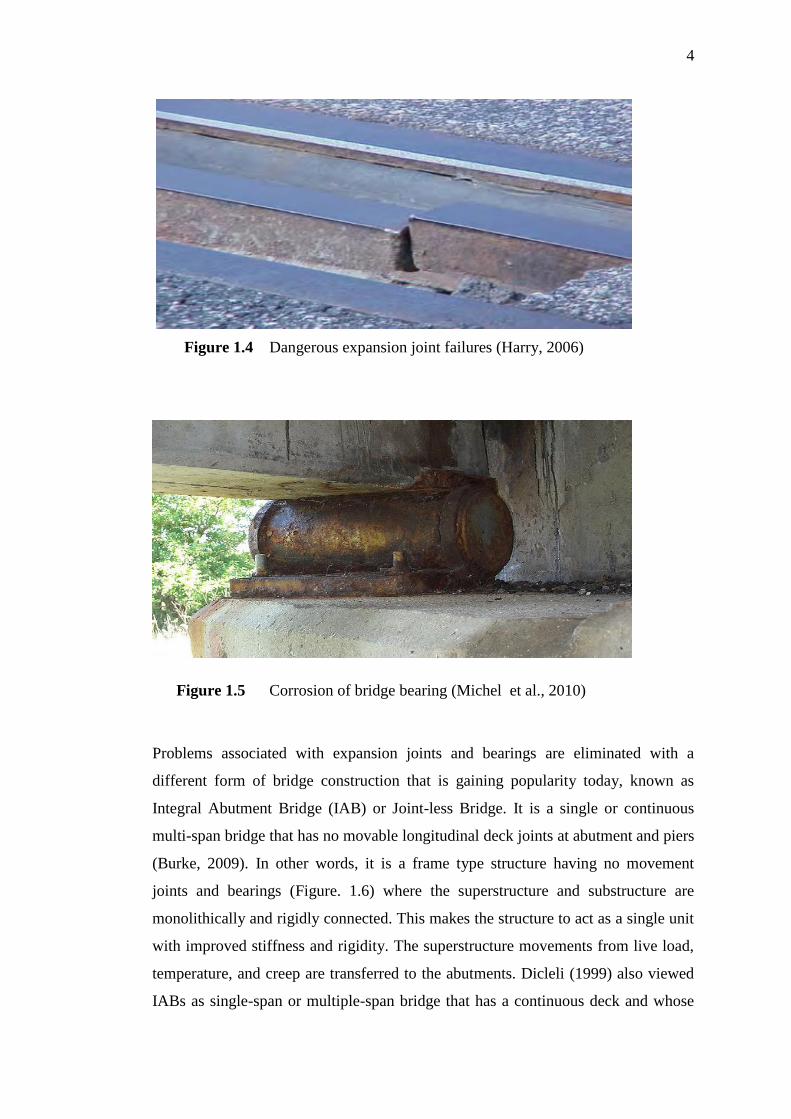
Figure 1.4 Dangerous expansion joint failures (Harry, 2006)
Problems associated with expansion joints and bearings are eliminated with a
different form of bridge construction that is gaining popularity today, known as
Integral Abutment Bridge (IAB) or Joint-less Bridge. It is a single or continuous
multi-span bridge that has no movable longitudinal deck joints at abutment and piers
(Burke, 2009). In other words, it is a frame type structure having no movement
joints and bearings (Figure. 1.6) where the superstructure and substructure are
monolithically and rigidly connected. This makes the structure to act as a single unit
with improved stiffness and rigidity. The superstructure movements from live load,
temperature, and creep are transferred to the abutments. Dicleli (1999) also viewed
IABs as single-span or multiple-span bridge that has a continuous deck and whose
Figure 1.5 Corrosion of bridge bearing (Michel et al., 2010)

5
only mechanism of movement is abutment that is supported on flexible piles. This
structural arrangement results in transferring the cyclic movement of the bridge
superstructure to all substructure components. Consequently, soil-substructure
interaction namely backfill-abutment and soil-pile foundation interaction affects the
bridge movement and has been identified as the key factor influencing the behaviour
of IABs (Faraji et al., 2001; Khodair, 2005). The stiffness of backfill provides
resistance to longitudinal bridge movement due to thermal and breaking loads
(British highway agency, 2003).
Figure 1.6 Scheme of an Integral Abutment Bridge
Integral connection of bridge superstructure and abutment in IAB eliminates the
need for joints, bearings, and the cost for their maintenance. This system simplifies
construction procedure and enhances structural performance of bridges as a result of
the rigidity of superstructure-abutment connection. IABs have therefore become
popular in many countries due to their functional and economic advantages. In UK
and Ireland in particular, bridges not exceeding 60 m span and 300 skew are now
required to be designed as IAB (O’brien and Keogh, 2005). Many transportation
agencies in the US and Canada prefer the choice of IABs (Dicleli and Erhan, 2009).

6
1.3 Overview of Integral Abutment Bridge
Bridges constructed before the 20
th century (1900) were Integral Abutment
Bridges (IABs). As bridges span longer distances in 20th century, expansion joints
or movement joints were introduced to accommodate thermal movement. Expansion
joints are now gradually removed from bridge designs to reduce the high cost of
maintenance thereby retuning back to earlier design pattern (Nicholson, 1998).
Jointless bridges began to be developed on experimental basis, with short bridges
ranging from 15 m to 30 m, during the 1930s in the United States, Australia and
New Zealand. Due to the absence of rational design guides, bridge length was
subsequently increased based empirically on successful performance of other
bridges. This led different highway transport agencies developing their own design
criteria and length limitations (Wolde-Tinsae et al., 1988).
In traditional highway bridges, movement joints and bearings are usually
provided to allow structural movement due to thermal variation, creep and shrinkage
(Arockiasamy et al., 2004). In the 1960s when traffic loads increased in volume,
weight and speed, there was increased demand for maintenance of joints and
bearings (Wolde-Tinsae et al., 1988). Maintenance and replacement works became
more regular consuming a major share of bridge maintenance budget. Gradual
deterioration of expansion joints form heavy impacts of bridge live loads, thermal
expansions and contractions, creep, shrinkage contractions and foundation
settlement leads to leakage of salt laden water form bridge surface to underneath of
bridge deck, corroding bridge girder, bearings and reinforced concrete substructures.
The problem is exacerbated in regions that experience heavy snow where de-icing
chemicals like sodium chloride and calcium chloride are commonly used (Kier,
2009). The problem is magnified when the drainage troughs are not functioning
properly due to accumulation of dirt. In addition to structural damage, leaky joints
give unpleasant aesthetic appearance requiring regular cleaning and repainting.
Studies have linked faulty expansion joints and/or the attendant maintenance
operations to road accidents and hazardous roadway condition (Rabih Haj-Najib,
2002). Elastomeric glands also become filled with water and dirt leading to its
eventual failure (Mistry, 2005). Different types of expansion joints are manufactured

7
to accommodate varied types of movements, some with improved performance over
others, but all expansion joints eventually fail with time leading to expensive repair
and replacement works.
In view of the numerous problems associated with expansion joints, jointless
bridges become an alternative to destructive effect of leaking and freezing deck
joints (Burke, 1993). In addition to reduction in high cost of maintenance,
construction process is simplified and construction cost is reduced with the removal
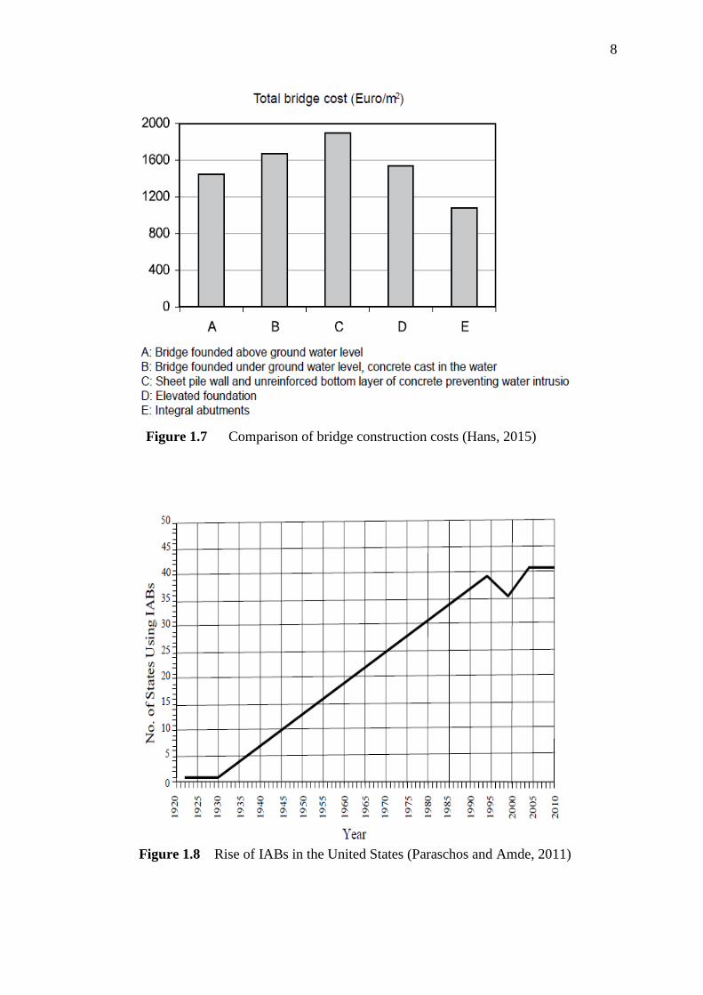
of joints and bearings (Griemann et al.,, 1986; Hans and Peter, 2006). Studies by
Hans (2015) have shown that significant savings in bridge construction costs is
achieved with the use of IABs (Figure 1.7). IABs are therefore rapidly gaining
popularity; many states in US have resorted to the removal of joints and associated
bearings in the proposed and existing bridges to save cost (Figure 1.8). Kunin and
Alampalli (1999) discovered that nearly 10,000 IABs were built by 30 bridge
agencies in United States between 1969 and 1999. The number of Integral and
Jointless Bridges (IAJB) comprising both integral and semi-integral abutment
bridges (that has abutments-girder joints) amounted to 13,000 in U.S. according to
survey conducted by Rodolf and Samer in 2005 (Table 1.1). In the ten years
preceding the survey, US had a 200 % surge in number of IABs. Over 1000 IABs
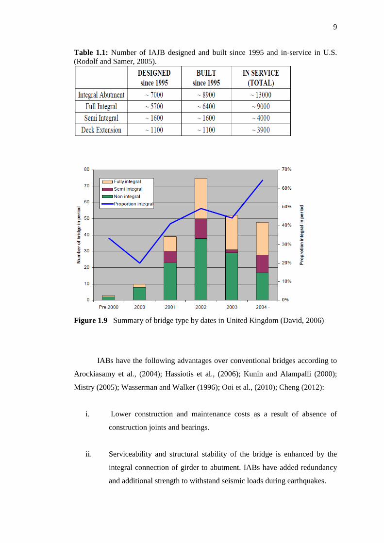
were built in Finland during recent decades (Olli et al., 2005). Figure 1.9 shows
increase in use of IABs in UK within a four year period. Bridge maintenance costs
of jointed bridges have been a source of concern for many bridge agencies.
Experience from US, Sweden and many countries have shown that IABs are a better
alternative due lower financial demand for their construction and maintenance
(Feldmann et al., 2006).
8
Figure 1.7 Comparison of bridge construction costs (Hans, 2015)
Figure 1.8 Rise of IABs in the United States (Paraschos and Amde, 2011)
9
Table 1.1: Number of IAJB designed and built since 1995 and in-service in U.S.
(Rodolf and Samer, 2005).
Figure 1.9 Summary of bridge type by dates in United Kingdom (David, 2006)
IABs have the following advantages over conventional bridges according to
Arockiasamy et al., (2004); Hassiotis et al., (2006); Kunin and Alampalli (2000);
Mistry (2005); Wasserman and Walker (1996); Ooi et al., (2010); Cheng (2012):
i. Lower construction and maintenance costs as a result of absence of
construction joints and bearings.
ii. Serviceability and structural stability of the bridge is enhanced by the
integral connection of girder to abutment. IABs have added redundancy
and additional strength to withstand seismic loads during earthquakes.
10
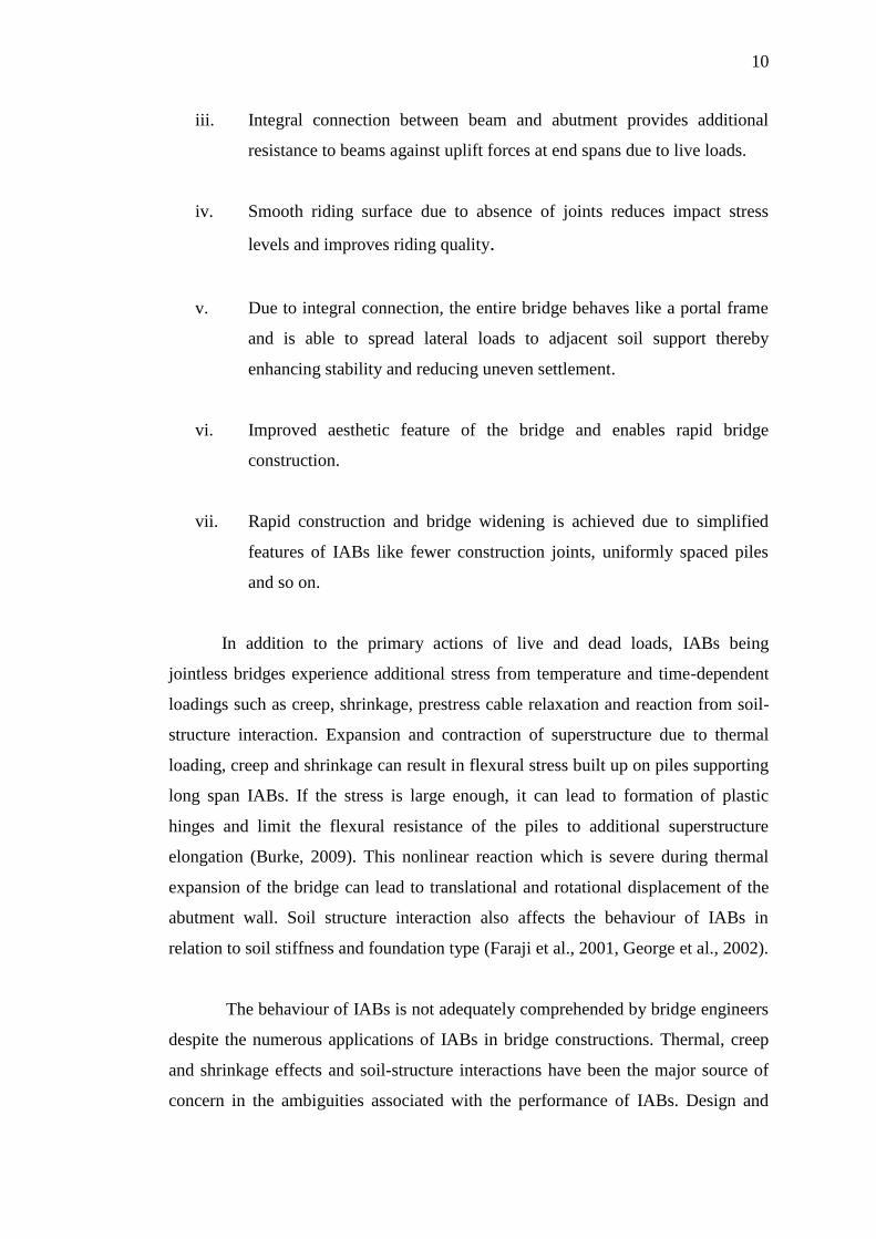
iii. Integral connection between beam and abutment provides additional
resistance to beams against uplift forces at end spans due to live loads.
iv. Smooth riding surface due to absence of joints reduces impact stress
levels and improves riding quality.
v. Due to integral connection, the entire bridge behaves like a portal frame
and is able to spread lateral loads to adjacent soil support thereby
enhancing stability and reducing uneven settlement.
vi. Improved aesthetic feature of the bridge and enables rapid bridge
construction.
vii. Rapid construction and bridge widening is achieved due to simplified
features of IABs like fewer construction joints, uniformly spaced piles
and so on.
In addition to the primary actions of live and dead loads, IABs being
jointless bridges experience additional stress from temperature and time-dependent
loadings such as creep, shrinkage, prestress cable relaxation and reaction from soil-
structure interaction. Expansion and contraction of superstructure due to thermal
loading, creep and shrinkage can result in flexural stress built up on piles supporting
long span IABs. If the stress is large enough, it can lead to formation of plastic
hinges and limit the flexural resistance of the piles to additional superstructure
elongation (Burke, 2009). This nonlinear reaction which is severe during thermal
expansion of the bridge can lead to translational and rotational displacement of the
abutment wall. Soil structure interaction also affects the behaviour of IABs in
relation to soil stiffness and foundation type (Faraji et al., 2001, George et al., 2002).
The behaviour of IABs is not adequately comprehended by bridge engineers
despite the numerous applications of IABs in bridge constructions. Thermal, creep
and shrinkage effects and soil-structure interactions have been the major source of
concern in the ambiguities associated with the performance of IABs. Design and

11
construction of IABs was therefore dependent on past experience as there is no
design guide available in the existing codes of practice for IABs (Huang et al.,
2008).
1.4 Problem Statement
In spite of IABs having functional and economic advantages over
conventional bridges, there are many uncertainties regarding their behaviour that
need to be fully understood. Most of these uncertainties arise as a result of
elimination of movement joints leading to lateral movements occurring at bridge
abutments. Removal of movement joints result in uncertainties relating to
complexities in soil-structure interaction and nonlinear material behaviour. Bridge
superstructures of IABs do experience cyclic expansion and contraction due to
thermal load variation against passive resistance of backfill behind bridge abutment.
In addition to this thermally induced superstructure and abutment displacement,
nonlinear creep and shrinkage of bridge deck and girder create additional
contraction of the superstructure and abutment against lateral resistance of piles
supporting bridge abutment. Thermal movement, time-dependent response and soil
structure-interaction makes the behaviour of IABs not fully understood (Huang et
al., 2004; Ooi et al., 2010; Arockiasamy et al., 2004).
The absence of a unified design code that clearly defines the procedure for
design of IABs is a point of concern that necessitates the need for further study on
the behaviour of IABs. The practice of design and construction of IABs is mainly
empirical in nature rather than systematic investigation (Arockiasamy and
Sivakumar, 2005). There is no clearly defined analysis method and standardised
design procedures in the current design specifications and guides; the behaviour is
therefore unknown and the design is cumbersome resulting in low utilisation of
IABs despite the enormous benefits (Kim and Laman, 2010a; Thippeswamy et al.,
2002). There is therefore the need to further enrich our present limited

12
understanding of behaviour of IABs under effects of temperature, creep and
shrinkage.
1.5 Research Objectives
The behaviour of continuous prestressed concrete girder IABs under
temperature and creep loads was studied in this research. This study has achieved
the following objectives:
i) Developing a three dimensional finite element model that effectively
predicts the effect of creep, shrinkage and thermal loadings on the
performance of long spanning IABs.
ii) Quantifying the effect of creep and shrinkage on moment and shear
capacities of prestress concrete girders of IAB.
iii) Proposing empirical model equations that can serve as guide in
predicting long term response of IABs to creep loading. The equations
should contribute to safe design of long span IABs beyond the current
practice of limiting the span of IABs to 60 m.
1.5 Scope of Research
The research is conducted through numerical analyses using Finite Element
Method. Modified Newton Raphson iteration method was used in nonlinear
transient creep analyses of prestressed concrete slab on T beam IABs using CEB-
FIP (1990) creep model for 75 years. The post tensioned IABs have no skew or
curvature. Four IABs lengths were 60 m, 90 m, 120 m and 150 m with each bridge
having pier to pier spans of 20 m, 30 m, 40 m and 50 m respectively. Linear
Thermal analyses were conducted to study the response of the bridge to thermal
loading in tropical climate. An average temperature range of 210C to 36
0C was

13
chosen within the range of Malaysian climate (Malaysian Metrological Department,
2015) which was adopted as case study of the research. Soil behind bridge piles
were varied form dense sand, medium dense sand, loose sand, stiff clay, medium
stiff clay to soft clay to study the response of backfill and piles on bridge movement
due to thermal and time-dependent loadings. Soil was modelled using linear springs
and the spring stiffness was obtained with the use of force displacement curves (P-y
curves).
1.6 Research Methodology
The Reseach was conducted through numerical analyses using finite element
method and the analyses were carried out in finite element software LUSAS.
Figure 1.10 provides flowchart of the step by step procedure followed in carrying
out the reseach. Literature was reviewed and presented in Chapter two to establish
research gap in previous studies on thermal and time-dependent behaviour
performance of integral abutment bridge due to temperature, creep and shrinkage
loadings. The research gap, as presented in Section 2.9 formed the research problem
to be solved and the overall objective of the research. Structural design of IAB
carried out using BS8110 (1997) code, was based on an existing IAB in Johor Bahru
Malaysia. Three dimensional finite element models of IABs were developed to
represent structural components of the bridge. Prestressing force was modelling
using equivalent load method and the girder and the prestresssing tendon were
modelled as single beam element. Soil-structure interaction for both backfill-
abutment and soil-pile interaction were modelled using Clough and Duncan and p-y
curve methods respectively. Nonlinear beam element with CEB-FIP 1990 code
creep and shrinkage material properties was used to model prestressed concrete
girders for the 75 years creep analyses. Linear beam elements were used to model
girders for thermal loading. Models were tested by subjecting them to thermal and
creep loadings in addition to live, dead and prestress loadings to obtain preliminary
results which were validated using analytical procedure. Parametric analyses were
carried out and the parameters considered are thermal load, creep and shrinkage,

14
bridge length and stiffness of substructure soil.Loss in prestress loss, changes in
creep coefficient, reduction in moment and shear capacities of prestress concrete
girders of IABs were computed at the end of the analyses. Results of the analyses
were used to develop empirical equations that can be used in long-term response
prediction of IABs to creep loading. The equations were tested and validated to
establish their accuracy and a conclusion was made on the usefulness of the
equations in early predictive assessment of long-term performance of IABs to creep
loading.

15
Figure 1.10 Flowchart of research methodology
Literature review and research gap identification
Problem statement and definition of research objectives
IAB design and development of 3D FE model
75 years FE simulation under creep load and analyses of parametric study results
Testing and validation of Empirical Equations
Testing and validation of FE results
Structure
Element of
IAB
Prestressing
force and
Bridge loads
Soil-
structure
interaction
Creep and
thermal
loadings
Conclusion
FE simulation under thermal load and analyses of parametric study results
Development of Empirical Equations from analyses results
Calculation of prestress loss, moment and shear capacity of IAB girders for 75
years of creep and shrinkage loading

16
1.7 Layout of Thesis
Chapter one presents the background of the research and explains the concept of
IABs and their attributes. It also discussed limitations of IABS which formed the
basis of the research problems, objectives, methodology and scope as discussed in
the chapter.
Chapter two is a review on relevant literature to provide background knowledge of
the research, prior research work conducted and what has not been adequtely
covered by previous study which formed the basis of the present study. The topics
covered include Concept and types of IAB, global approaches in its utilisation,
secondary loading effects on the bridge, temperature and creep models and soil-
structure interaction modelling.
Chapter three provides discussion on method used in finite element modelling of
post-tensioned cable profile for continuous bridge girders and other structural
elements of the bridge. Procedure followed in modelling soil-structure interaction
for abutment-backfill interaction and pile-soil interactions under varying soil types
were fully discussed. Results from finite element modelling were validated in this
chapter.
Chapter four provided parametric study results for both creep and thermal loadings
of IABs. The results of the analysis of 60 m 90 m, 120 m and 150 m, IABs are
presented and explained. Empirical equations were developed, tested and validated.
Chapter five provides concluding aspects of the research. It discusses the research
findings and achievements and provided general conclusion based on the research
findings. It also provides recommendations for further studies on IABs.
238
REFERENCES
AASHTO (2007), American Association of State Highway and Transportation
Officials, Load and Resistance Factor Design bridge design specifications.
4th Edition, Washington, DC.
ACI (1992), American concrete Institute, Prediction of Creep, Shrinkage, and
Temperature Effects in Concrete Structures, 209R-92, ACI Committee 209,
Farmington Hills, MI 48331
Antoine, E., M. (2004) Prestressed Concrete Analysis and Design Fundamentals,
Second Edition, Techno Press, Michigan.
Arockiasamy, M., Butrieng, N., and Sivakumar, M. (2004). State-of-the-art of
integral abutment bridges: Design and practice. Journal of Bridge
Engineering, 9(5), 497-506.
Arockiasamy, M., and Sivakumar, M. (2005). Time-Dependent Behaviour of
Composite Integral Abutment Bridges. Practice Periodical of Structural
Design and Construction Volume 10 No.3, .
Au, F. T. K., and Si, X. T. (2011). Accurate time-dependent analysis of concrete
bridges considering concrete creep, concrete shrinkage and cable relaxation.
Engineering Structures, 33(1), 118-126.
BadwaterJournal.com (2011) Road Salt corrosion on the Sherma Minton Bridge, 1
64 at West Louisville retrieved from http://badwaterjournal.com/Bad_ Water
_Journal/ Sherman_Minton.html.
Baptiste, K. T., Kim, W., and Laman, J. A. (2011). Parametric study and length
limitations for prestressed concrete girder integral abutment bridges.
Structural Engineering International: Journal of the International Association
for Bridge and Structural Engineering (IABSE), 21(2), 151-156.
Barker, R. M., Duncan, J. M. K., Rojiani, K. B., Ooi, P. S. K, Kim, S.G., (1991).
Manuals for the Design of Bridge Foundation, NCHRP Report 343,

239
Transportation Research Board, National Research Council, Washington,
D.C.
Bhatt, P., (2011) Pretressed Concrete Design to Eurocodes, Routledge, New York.
Bowles, J. E., (1996). Foundation Analysis and Design, 5th Edition, McGraw-Hill,
New York.
Braun, A., Seidl G., Weizennegger, M. (2006) Frame Structures in Bridge
construction, Design, Analysis and economic consideration, Proceedings of
International Workshop on the Bridges with Integral Abutments organised
by Division of Structural Engineering, Department of Civil and
Environmental Engineering, Luleå University of Technology.
BCMOT (2007) Bridge Standards and Procedures Manual, v1, supplement to
CHBDC S6-06, British Colombia Ministry of Transportation, London.
British Highway Agency (2003) BA 42/96: The Design of Integral Bridges, Design
Manual for Roads and Bridges, The stationary office, London.
British Standard Institute (1990) BS5400 Part 4 Code of practice for design of
concrete bridges, British Standards Online, bsonline.techindex.co.uk.
British Standard Institute (1997) BS58110 Part 1 Structural use of concrete, British
Standards Online, bsonline.techindex.co.uk.
Burke, M. P. (1993). Design of Integral Concrete Bridges. Concrete International,
15,6, 37-42.
Burke, M. P. (2009). Integral and Semi-Integral Bridges. Wiley-Blackwell, West
Sussex.
Canadian Standards Association, (2006). Canadian Highway Bridge Design Code.
CAN/CSA-S6-06, 10th edition, Ontario.
CEB-FIP Model code (1990), Code for concrete structures, Comite Euro-
International du Beton, Thomas Telford, London.
Chandra, S. (2014) Spring Modelling of soil behaviour, Indian Institute of
Technology, Kurukshetra, http://home.iitk.ac.in/~peeyush/mth426/Lec4_ schandra.
Cheng, L. (2012) On the performance of Super-long Integral Abutment Bridges-
Parametric Analysis and design optimisation, PhD thesis submitted to
Department of Civil and Mechanical Structural Systems, University of
Trento.

240
Civjan, S. A., Bonczar, C., Brena, S. F., Dejong, J., and Crovo, D. (2007). Integral
abutment bridge behavior: Parametric analysis of a massachusetts bridge.
Journal of Bridge Engineering, 12(1), 64-71.
Clough, G. M.and Duncan, J. M., (1991). “Chapter Six/Earth pressures” in
Foundation Engineering Handbook, pp 224-34, Edited by H. Y., Fang, 2 Nd
Edition, Chapman and Hall, New York,
Collin, P., Veljkovic, M., and Petursson, H. (2006). International Workshop on
Bridges with Integral Abutments, Lulea University of Technology, Lulea,
Sweden.
David, C. I. (2006) Integral Bridges in the UK, International Workshop on the
Bridges with Integral Abutments, Department of Civil and Environmental
Engineering, Luleå University of Technology, Sweden.
Debbarma, S.R.,and Saha, S. (2011) Behaviour of pre-stressed concrete bridge
girders due to time dependent and temperature effects, First middle east
conference on smart monitoring, assessment and rehabilitation of civil
structures, Dubai.
Dicleli, M (1999) A rational design approach for prestressed-concrete girder
Integral Bridges, Engineering Structures, 22(3):230-245, DOI: 10.1016/
S0141-0296(98)00080-7
Dicleli, M. (2000a). Simplified model for computer-aided analysis of integral
bridges. Journal of Bridge Engineering, 5(3), 240-248.
Dicleli, M. (2000b). A rational design approach for prestressed-concrete-girder
integral bridges. Engineering Structures, 22(3), 230-245.
Dicleli, M., and Albhaisi, S. M. (2003). Maximum length of integral bridges
supported on steel H-piles driven in sand. Engineering Structures, 25(12),
1491-1504.
Dicleli, M., and Albhaisi, S. M. (2004a). Performance of abutment–backfill system
under thermal variations in integral bridges built on clay. [doi:
10.1016/j.engstruct. 2004.02.014]. Engineering Structures, 26(7), 949-962.
Dicleli, M., and Albhaisi, S. M. (2004b). Estimation of length limits for integral
bridges built on clay. Journal of Bridge Engineering, 9(6), 572-581.
241
Dicleli, M. (2005). "Integral Abutment-Backfill Behavior on Sand Soil—Pushover
Analysis Approach." Journal of Bridge Engineering, 10.1061/(ASCE)1084-
0702(2005)10:3(354), 354-364.
Dicleli, M., & Erhan, S. (2009). Live load distribution formulas for single-span
prestressed concrete integral abutment bridge girders. Journal of Bridge
Engineering, 14(6), 472-486.
Dicleli, M., & Erhan, S. (2010). Effect of soil–bridge interaction on the magnitude
of internal forces in integral abutment bridge components due to live load
effects. [doi: 10.1016/j.engstruct.2009.09.001]. Engineering Structures,
32(1), 129-145.
Dongya, A., Chengming L., Jiahua Z., Jiachun C., & Tian, W. (2010). The
Engineering Practice of Elasto-plastic Dynamic Time-history Analysis on
Complex Building Structures Using Abaqus, Paper presented at the Sumulia
Customer Conference.
Duffie, J.A. and Beckman, W.A. (1980). Solar Engineering of Thermal Processes,
Second Edition, John Wiley & Son, Inc., Hoboken, New Jersey
Emseal Infrastructure & Civil Products (2014) Replacement of failed Bolt-Down
expansion joints with EMCRETE and BEJS para 1 retrieved from
http://www.emseal.com/Products/Infrastructure/BridgeJointSeals/BEJSBridg
eInFailedBoltDowns.htm
England, G., L. and Tsang, C., M. (1996) Thermally Induced Problems in Civil
Engineering Structures, Thermal stresses iv, Elsevier Science, London.
Eugene, J. O., and Damien, L. K. (1999) Bridge Deck Analysis. E & FN Spon
London.
European Committee for Standardization (2003) EN 1991 Eurocode 1: Actions on
structures - Part 1-5: General actions -Thermal actions, EN 1991-1-5: 2003
(E).
Faraji, S., Ting, J. M., Crovo, D. S., and Ernst, H. (2001). Nonlinear analysis of
integral bridges: Finite-element model. Journal of Geotechnical and
Geoenvironmental Engineering, 127(5), 454-461.
Feldmann, M., Hechler,O.and Pak, D. (2006) Economic and Durable Design of
Composite Bridges with Integral Abutments, International Workshop on
the Bridges with Integral Abutments organised by Division of Structural
242
Engineering, Department of Civil and Environmental Engineering, Luleå
University of Technology, Luleå.
Fennema, J. L., Laman, J. A., and Linzell, D. G. (2005). Predicted and measured
response of an integral abutment bridge. Journal of Bridge Engineering,
10(6), 666-677.
Freyermuth , C. L. (1969). Design of Continuous Highway Bridges with Prestressed
Concrete Girders, PCI Journal, Vol. 14 , No. 2 .
George, L. E., Tsang N. C. M., and Bush, D. I. (2002). Integral Bridges: a
fundamental approach to time temperature loading problem, Thomas
Telford, London.
Ghali, A. Favre, R. and Elbadry, M. (2002). Concrete Structures Stresses and
Deformations, (Third Edition ed.). E & FN SPON, London:
Gilbert, R. I., (1998). Time effects in concrete structure, Elsevier, Amsterdam
Greimann, L.F., Yang, P.S., and Wolde-Tinsae, A.M. (1986), Nonlinear Analysis of
Integral Abutment Bridges, Journal of Structural Engineering, ASCE, Vol.
112, No. 10, 1986, pp. 2263-2280.
Haliburton, T. A., (1971). Soil-structure Interaction; Numerical Analysis of Beams
and Beam Columns, Technical Publication No. 14, School of Civil
Engineering, Oklahoma State University, Stillwater, Oklahoma.
Hambly, E., C. (1991) Bridge Deck Behaviour, Second Edition, Taylor and Francis,
New York.
Hans, P. and Peter, C. (2006). Innovative Solutions for Integral Abutments,
International Workshop on the Bridges with Integral Abutments, Department
of Civil and Environmental Engineering Division of Structural Engineering,
University of Technology, Luleå
Hans, P., (2015). Design of Steel Piles for Integral Abutment Bridges, Doctoral
Theisis submitted to Division of Structural Engineering. Department of Civil
and Environmental Engineering, Luleå University of Technology, Luleå.
Harry L. W. (2005). Integral Abutments: The New York Experience, Proceedings
of The 2005 – FHWA Conference Integral Abutment and Jointless Bridges
organized by Constructed Facilities Center, College of Engineering and
Mineral Resources, West Virginia University.

243
Hassiotis, S. S., Khodair, Y., and Roman, E., Dehne, Y., (2006). Evaluation of
Integral Abutments, Final Report, FHWA-NJ-2005-025. New Jersey
Department of Transportation, U.S.A.
Huang, J., French, C. E.,and Shield C.K.(2004). Behavior of Concrete Integral
Abutment Bridges, Research Reports,University of Minnesota, Minneapolis.
Huang, J., Shield, C. K., and French, C. E. W. (2008). Parametric study of concrete
integral abutment bridges. Journal of Bridge Engineering, 13(5), 511-526.
Hurst, M. K., (2003) Prestressed concrete design, Second Edition, E&FN Spon,
London.
JKR (1996). The New JKR Standard beams. Unit Jambatan, Kerja Raya Malaysia
Kalayci, E., Breña, S. F., and Civjan, S. A. (2009). Curved integral abutment
bridges - thermal response predictions through finite element analysis.
Conference paper presented at Structures 2009: Don't Mess with Structural
Engineers, conference organised by American Society of Civil Engineers.
Kaufmann, W. and Alvarez, M. (2011). Swiss Federal Roads office guidelines for
Integral Bridges, Structural Engineering International, 21,2,189-194
Kenneth F. D., and Dajin L., (2007). Foundations for Integral Abutments. Practice
Periodical on Structural Design and Construction 12(1), 22-30.
Khodair, Y. A., and Hassiotis, S. (2005). Analysis of soil-pile interaction in integral
abutment. Computers and Geotechnics, 32(3), 201-209.
Kier, D., (2009) Modeling of Integral Abutment Bridges Considering Soil-Structure
Interaction Effects, PhD Theisis Submitted to University of Oklahoma
Kim, W., and Laman, J. A. (2010a). Numerical analysis method for long-term
behavior of integral abutment bridges. Engineering Structures, 32(8), 2247-
2257. [doi: 10.1016/j. engstruct. 2010.03.027].
Kim, W., and Laman, J. A. (2010b). Integral abutment bridge response under
thermal loading. Engineering Structures, 32(6), 1495-1508.
Kong, F. K. and Evans, R. H. (1987). Reinforced and prestressed concrete
incorporating BS8110 and microcomputer applications, 3rd
edition, Springer,
London.
Kong, B., Cai, C.S. & Zhang, Y. (2016). Parametric study of an integral abutment
bridge supported by prestressed precast concrete piles, Engineering
Structures, Volume 120, 1, pp 37–48, http://dx.doi.org/10.1016/j. engstruct.

244
2016.04. 034
Kong, B., Cai, C.S.,and Kong, X., (2015). Field monitoring study of an integral
abutment bridge supported by prestressed precast concrete piles on soft soils
Engineering Structures, Volume 104, Pages18–31, http://dx.doi.org/10.101
6/j.engstruct.2015.09.004
Kramer, S.L. (1998). Development of P-Y curves for analysis of laterally loaded
piles, Technical report produced by Washington state department of
transport and U.S. department of transport federal highway administration.
Kroplin, B., and Weihe, S.(1997). Aspects of fracture induced anisotropy. Proc. of
5th International conference on computational plasticity (COMPLAS5),
Barcelona, 255-279,
Kunin, J. and Alampalli, S., (1999) Integral Abutment Bridges: Current Practice in
the United States and Canada. Special Report 132, Transportation Research
and Development Bureau, New York State Department of Transportation,
Albany, New York
Kunin, J., and Alampalli, S. (2000). Integral abutment bridges: Current practice in
United States and Canada. Journal of Performance of Constructed Facilities,
14(3), 104-111.
Larsson, and Svensson, (2013) .Realistic Modelling of Thermal Effects in Concrete
Bridges, Master's degree dissertation, Division of Structural Engineering,
Lund Institute of Technology, Lund University.
Lehane, B., Keogh, D.L. and O’Brien,E.J. (1996). Soil-structure interaction analysis
for integral bridges, Advances in Computational Methods for Simulation,
Civil-Comp Press, Edinburgh, pp201-10
Lin, T.Y. and Burns, N. H. (1980). Design of prestressed concrete structures, John
Wiley, New York.
LUSAS (2008a) Theory Manual Volume1, version 14 issue1, Finite Element
Analysis Ltd, Surrey.
LUSAS (2008b) Theory Manual Volume2, version 14 issue1, Finite Element
Analysis Ltd, Surrey.
Malaysian Metrological Department (2015). Monthly weather Bulletin of Malaysian
metrological Department, Ministry of Science Technology and innovation.
245
Available:http://www.met.gov.my/web/metmalaysia/publications/bulletinpre
view/ monthlyweather
Matlock, H. (1970). Correlation for Design of Laterally Loaded Piles in Soft Clay,
Proceedings of Offshore Technology Conference, Houston, Texas, (OTC
1204). P577-594
Mattock, A. H. (1961) Precast-Prestressed concrete bridges-Creep and Shrinkage
Studies, Journal of the PCA Research and Development Laboratories,
Portland Cement Association, Vol.3, No.2.
Michel, B., Myrto, A., and Alessandro, P., (2010). Preliminary Report on Bridge
Damage from the Darfield (New Zealand) M7.1 earthquake of September 4,
2010 – Draft of 2010-09-23, retrieved from http://eqclearinghouse.org
/co/20100903-christchurch/reports-from-the-field/preliminary-report-on-
bridge-damage-from-the-darfield-new-zealand-m7-1-earthquake-of-
september-4-2010
Mistry, V. (2005) Integral Abutment and Jointless Bridges, proceedings of The 2005
– FHWA Conference, Constructed Facilities Centre College of Engineering
and Mineral Resources, West Virginia University Baltimore, Maryland
USA.
Narong, T. (2006) Curved Integral Abutment Bridges, PhD research Dissertation
submitted to the Faculty of the Graduate School of the University of
Maryland, College Park, USA.
National Cooperative Highway Research Program (NCHRP 1991). Manuals for the
design of bridge foundations, Editors, Barker RM, Duncan JM, Rojiani KB,
Ooi PSK, Tan CK, Kim SG, Rep. 343, Transportation Research Board,
Washington, D.C.;.
Nawy, E. G., (2003) Prestressed Concrete A Fundamental Approach, 4th Edition,
Prentice-Hall, New Jersey.
Nicholson, B. A., (1998) Integral abutments for Prestressed Beam Bridges,
Prestressed Concrete Association, Leicester.
Noorzaei, J., Abdulrazeg, A. A., Jaafar, M. S., and Kohnehpooshi, O. (2010)
Non-linear analysis of an integral bridge. Journal of Civil Engineering and
Management, 16(3), 387-394.

246
O’Brien E. J. and Keogh D. L., (2005). Bridge Deck Analysis, E & FN Spon,
London.
Olli, K., L. and Anssi, L (2005) Soil-Structure Interaction of Jointless Bridges,
Proceedings of FHWA Conference, Constructed Facilities Center, College of
Engineering and Mineral Resources, West Virginia University, Baltimore,
Maryland.
Ooi, P. S. K., Lin, X., and Hamada, H. S. (2010). Numerical study of an integral
abutment bridge supported on drilled shafts, Journal of Bridge Engineering,
15(1), 19-31.
Papanicolaou, G.C. and Zaoutsos, S. P. (2011). Viscoelastic constitutive modelling
of creep and stress relaxation in Polymers and polymer matrix composites,
Creep and fatigue in polymer matrix composites, Woodhead Publishing
Limited, Cambridge, UK.
Paraschos, A., and Amde, M.A., (2011). “A survey on the status of use, problems,
and costsassociated with Integral Abutment Bridges”, Better Roads
Magazine, February.
Prab, B., Thomas, J., and Ban, S. C. (2006) Reinforced Concrete Design Theory and
Examples, Taylor and Francis, New York.
Prakash, S.,and Sharma, H.D. (1990) Pile Foundations in Engineering Practice, John
Wiley, New Jersey.
Pugasap, K., Kim, W., and Laman, J. A. (2009). Long-term response
prediction of integral abutment bridges. Journal of Bridge Engineering,
14(2), 129-139.
Rabih Haj-Najib, (2002) Integral Abutment Bridges with skew angles, Doctor of
Philosophy theisis sumbmitted to Department of Civil and Environmental
Engineering University of Maryland, College Park Maryland.
Raina, V. K. (1994) Concrete bridge practice, Analysis design and economics,
Second edition, Tata McGraw-Hill, New Delhi.
Raymond, I. G., and Gianluca, R. (2011). Time Dependent Behaviour of Concrete
Structures , Spon Press, New York.
René, B., Mike, A. C., Joris, J.C.R., and Clemens, V. V. (2012) Nonlinear Finite
Element Analysis for Solid and Structure, Second Edition, John Wiley &
Sons, Sussex, United Kingdom.
247
Reese, L.C., and Van Impe, W.F., (2001). Single Piles and Pile Group under Lateral
Loading.2 Nd Edition, CRC Press Taylor & Francis, leiden.
Reese, L. C., Cox, W. R., and Koop, F. D., (1974). Analysis of Laterally Loaded
Piles in Sand, Proceedings of 6th Annual Offshore Technology Conference,
Vol. 2 paper 2020, p 473-485, Houston Texas.
Rodolf, F., M., and Samer H. P. (2005) Integral Abutments and Jointless Bridges
2004 Survey Summary, Proceedings of THE 2005 – FHWA Conference
Integral Abutment and Jointless Bridges organized by Constructed Facilities
Center, College of Engineering and Mineral Resources, West Virginia
University.
Salgado, R., (2006) The Engineering of Foundations, McGraw-Hill, New York.
Skempton, A.W., (1951). The Bearing Capacity of Clays, Proceedings of Building
Research Congress, Volume 1, London.
Sophia, H.,Yaser, K.,Eugenia, R., and Yousef, D., (2006) Evaluation of Integral
Abutment, a research report, Department of Civil, Environmental and Ocean
Engineering Stevens Institute of Technology Hoboken, N.J. 07030
Springman, S.M., Norrish, A.R.M. and Ng, C.W.W.W (1996) Cyclic loading of
Sand Behind Integral Bridge Abutment, UK Highways, TRL Report 146,
London.
Suhail, A. (2012). Effect of Substructure Stiffness on the Performance of Integral
Abutment Bridges under Thermal Loads, a PhD dissertation in Civil and
Environmental Engineering submitted to the Graduate School-New
Brunswick Rutgers, The State University of New Jersey.
Teodru, I., (2009). Beams on Elastic Foundation the Simplified Continuum
approach, Bulettin of the Polytechnic Institute, Architectural Construction
department, Gheorghe Asachi Technical University, Iasi.
Terzaghi, K. (1955). Evaluation of coefficients of subgrade reaction. Geotechnique,
Vol. 5, No. 4, pp.297-326. Harvard soil mechanics series, 51
Thippeswamy, H. K., GangaRao, H. V. S., and Franco, J. M. (2002). Performance
evaluation of Joint-less bridges. Journal of Bridge Engineering, 7(5), 276-
289.

248
University of Michigan open-source (2014) Introduction to Bio-solid Mechanics,
Constitutive Equations: Viscoelasticity, retrieved from http://www.umich.
edu/~bme332/ch7consteqviscoelasticity/bme332consteqviscoelasticity.htm
University of Texas open source (2014). Lesson 14 Mechanical Properties of
Materials, retrieved from http://wweb.uta.edu/faculty/ricard/Classes/KINE-
301/Notes/Lesson-14.html
Voyiadjis, G. Z., Cai S., Alshibli, K., Faghihi, D., Kong, B. and Yang, Y. (2016).
Integral Abutment Bridge for Louisiana’s Soft and Stiff Soils, Final Report
517, Louisiana Transportation Research Center, Department of Civil and
Environmental Engineering, Louisiana State University, Baton Rouge, LA
70803.
Walter, H. D., Amin, G., Mathew, C., Mo. S. C., and Marc A. M. (1983)
Temperature Stresses in Composite Box Girder Bridges, Journal of
Structural Engineering, Vol. 109, No. 6, ASCE, ISSN 0733-9445/83/0006-
1460. Paper No. 18064.
Wang, S.T., and Isenhower, W.M., (2010). LPile user’s manual, Version 6, A
Program for the Analysis of Piles and Drilled Shafts Under Lateral Load,
Ensoft, Inc., p 68-74.
Wassermann, E. P. and Walker, J. H. (1996). Integral Abutments for continuous
steel bridges, Workshop on Integral abutment bridges, Pittsburgh, PA, 31 p.
Welch, R.C., and Reese, L.C., (1972). Laterally loaded behavior of drilled shafts,
Research Report 3-5-65-89. Center for Highway Research. University of
Texas, Austin.
White, H. (2007) Integral Abutment Bridges: Comparison of Current Practice
Between European Countries and the United States of America, Special
Report FHWA/NY/SR-07/152, Transportation Research and Development
Bureau, State Department of Transportation. New York.
White, H., Pétursson, H., and Collin, P., (2010). Integral Abutment Bridges: The
European Way, Practice Periodical on Structural Design and Construction,
ASCE, Vol. 15, No. 3, p 201-208.
Wolde-Tinsae, Made, M. A., Klinger, J. E., and White, E. J. (1988). “Performance
of Jointless Bridges.” Journal of Performance of Construction Facilities,
ASCE, Vol. 2, No. 2, pp. 111-125.

249
Yannotti A. P., Alampalli S., and White H., (2005) New York’s State Department of
Transportation’s experience with Integral Abutment and Jointless Bridges
(IAJB2005) Baltimore, Maryland, 4149
Zdenek, P., Bazant, F. and Jenn-Chuan C., (1983), Rate-Type Concrete Creep law
with reduced time Journal of Engineering Mechanics, Vol. 110, No.3.
Zordan, T., Briseghella, B., and Lan, C. (2010). Parametric and pushover
Analyses on integral abutment bridge. Engineering Structures, 33(2), 502-
515.[doi: 10.1016/j.engstruct.2010.11.009].