i- clean homogeneous configurations
TRANSCRIPT
N A S A T E C H N I C A L NOTE
, pt.1 I ' I
I c.1
s n CII
CRITICAL MASS STUDIES WITH NASA ZERO POWER REACTOR I1
I - CLEAN HOMOGENEOUS CONFIGURATIONS
bv Thomas A. Fox, Robert A. MzceZZer, J
C. Hnbbard Ford and Donald L. AZger
Lewis Research Center CZeveZand Ohio
N A T I O N A L A E R O N A U T I C S A N D S P A C E A D M I N I S T R A T I O N W A S H I N G T O N
TECH LIBRARY KAFB, NM
NASA TN D-3097
CRITICAL MASS STUDIES WITH NASA ZERO POWER REACTOR 11
I - CLEAN HOMOGENEOUS CONFIGURATIONS
By Thomas A. Fox, Robert A. Mueller, C. Hubbard Ford, and Donald L. Alger
Lewis Research Center Cleveland, Ohio
NATIONAL AERONAUTICS AND SPACE ADMINISTRATION
For sale by the Clearinghouse for Federal Scientific and Technical Information Springfield, Virginia 22151 - Price $1.00
.. . ~~ ~~~~

CRITICAL MASS STUDIES WITH NASA ZERO POWER REACTOR I1
I - CI;EAN HOMOGENEOUS CONFIGURATIONS
by Thomas A. Fox, Robert A. Mueller, C . Hubbard Ford, and Donald L. Alger
Lewis Research Center
SUMMARY
The NASA Zero Power Reactor I1 (ZPR-11) has been used t o determine experi- men ta l ly t he c r i t i ca l masses f o r more than a tenfold range of highly enriched (93.2 percent U235) aqueous uranyl f luoride fuel concentrat ions in c lean cyl in- drical geometries. The ZF’R-I1 reactor tank permits the assembly of cy l indr ica l cores 76.2 centimeters (30 in . ) in diameter and with lengths (heights) up t o 90 centimeters ei ther bare or r ad ia l ly r e f l ec t ed by about 15 centimeters (6 in.) of water The specific range of fuel concentrations was from hydrogen t o uranium2” atom r a t i o s of about 150 (167 g U235/liter of f u e l s o l u t i o n ) t o 1650 (15 g U235/li ter) .
I n a d d i t i o n t o t h e c r i t i c a l masses, data are presented on the temperature coef f ic ien t of r e a c t i v i t y and the incremental reactivity worth a t c r i t i c a l i t y f o r a similar range of concentrations. Some of the physical properties for the fuel concentrations are presented, based on measurements made a t the Lewis Research Center. A br ie f descr ip t ion of the ZPR-I1 and the experimental proce- dures used are also included.
INTRODUCTION
The NASA Zero Power Reactor I1 (ZPR-11) was designed and b u i l t by the NASA Lewis Research Center t o provide a tool for the study of heterogeneous inserts in solut ion cr i t ical systems. This reactor uses aqueous solut ions of highly enriched ( 93.2 percent U235 ) uranyl f luoride salt (U02Fz ) i n a cyl indrical tank with a diameter of 76.2 centimeters (30 i n . ) that is e i ther unref lec ted or r ad ia l ly r e f l ec t ed by about 15 cent imeters (6 in . ) of water. A range of c r i t i - c a l assemblies can be achieved by varying the fuel solution concentration. Control consists solely of solution height manipulation, thereby clean cylin- dr ica l geometr ies for c r i t i ca l i ty de te rmina t ions are provided.
k c h previous work has been reported involving cri t ical systems that use uranyl f luor ide so lu t ion fue l (e .g . , see refs. 1 and 2 ) . This study represents new parametric information because of the particular reactor vessel geometry involved. The c r i t i c a l i t y data for c lean homogeneous configurations are pre- sented; in addition, solution temperature coefficients and incremental height
/ -ZPR-I I fuel pump
r Z P R - I I c i r c u l a t i o n /
ZPR-I dump tanks-, Reactor room I Pump ZPR- I fu l
Control room Solut ion room . . - . . . .. ... . . . . . 7.77 . I . . . * ,
CD-8064
(a) Plan view.
1 . . I ’. .
Ai” .. Control room
storage tanks -’
-2PR- I I dump tanks
CD-8063
(b) Elevation view. Figure 1. - ZPR facility.
2
r e a c t i v i t y worth measurements f o r t h e systems studied are also included.
DESCRIPTION OF NASA ZPR-I1
The ZPR-I1 is one of two c r i t i c a l systems making up what i s presently known as the NASA Zero Power Reactor Facil i ty (ZPRF). The layout of the ZPRF i s shown i n f i g u r e 1. The f a c i l i t y proper includes a cont ro l room, reactor room, solut ion room, locker room, and a connecting hallway. The reactor room or test c e l l i s constructed of reinforced poured concrete and i s located under- ground t o minimize shielding problems. A 54-inch-thick (137 cm) wal l i s pro- vided between the reac tor room and the solut ion room t o permit access to the solut ion room a t a l l times.
The ZPR-I1 shares the reactor room with the Zero Power Reactor I (ZPR-I), a schematically similar but much smaller and separate system that uses the same kind of fuel. Both reactor vessels are mounted on a stand, so tha t the reac tor midplane i s about midway between the f l oo r and the ce i l i ng of the reactor room. The reactors are also located approximately a t epicenters of the reactor room (see plan view i n f i g . l ( a ) ) . These locations are intended to keep wall e f f ec t s i n a l l d i r ec t ions t o a minimum. The reactors use a single control console and instrumentation system to assure operat ion of only one r e a c t o r a t a time. The fuel p iping systems f o r the two reactors are separate and independent, but both are connected t o the solut ion room storage system and the vacuum d i s t i l l i n g apparatus used to concentrate fuel solut ion.
The ZPR-I and ZPR-I1 are both solut ion cr i t ical systems. Each consis ts e s sen t i a l ly of a geometrically safe fuel storage system, a reactor tank where various different configurations may be assembled, and a solution manipulating system that enables the experimenter to assemble remotely the critical reactor i n a controlled manner. The assembly takes place with the reactor room closed t o provide a s e a l e d t e s t c e l l , which gives both adequate shielding from d i r ec t rad ia t ion and protection from the airborne activity associated with the opera- t i on of such systems.
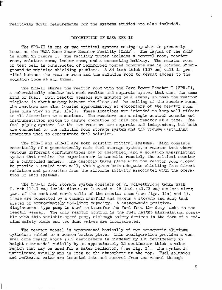
The ZPR-I1 fue l s torage system consis ts of 2 1 polyethylene tanks with 5-inch ( 1 2 . 7 cm) inside diameters located on 18-inch (45.72 cm) centers along p a r t of t he ea s t and north walls of the reactor room ( s e e f i g s . l ( a ) and 2 ) . These are connected by a common manifold and makeup a storage and dump tank system of approximately 550-liter capacity. A custom-made posi t ive- displacement type pump i s used t o t r a n s f e r the f u e l from t h e dump tanks t o the reactor vessel . The only reactor control i s the fuel height manipulation possi- b l e with this variable-speed pump, although safety devices in the form of a cad- m i u m safety blade and two dump valves are incorporated.
The reactor vessel i s constructed basically of two concentric aluminum cylinders welded t o a common bottom plate. This configuration provides a cen- t r a l core region about 76.2 centimeters i n diameter by 106 centimeters i n height surrounded radially by an approximately 15-centimeter-thick annular region that may be used for a water reflector, (see f i g . 3 ) . The system i s unref lected axial ly and is open t o t h e atmosphere a t the top. Fuel solution and re f lec tor water a re inser ted in to and removed from the vessel through
3
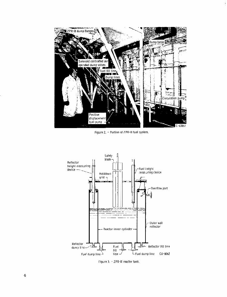
Figure 2. - Port ion of ZPR-II fuel system.
Safety n
Reactor inner cy l inder
Ref lector f i l l l ine
Fuel d u m p l i n e l i n e -/ LFuel d u m p l i n e CD-8062
Figure 3. - ZPR-II reactor tank.
4
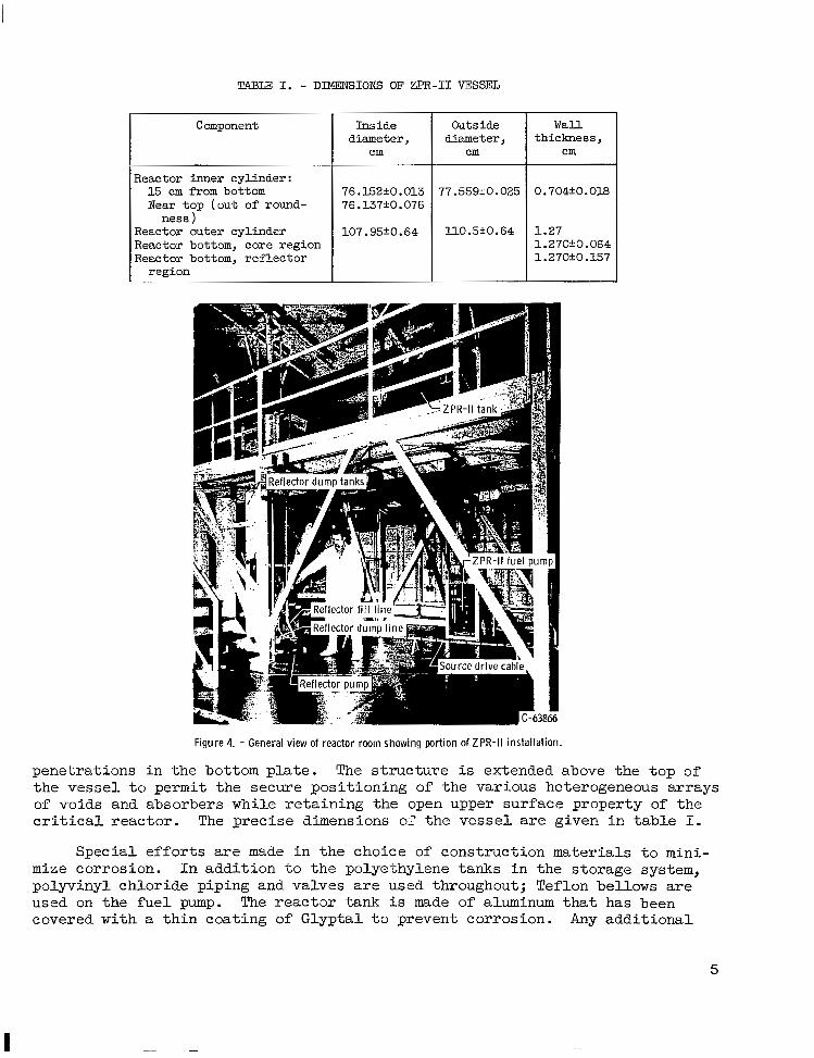
TABLE I. - DIMENSIONS OF ZPR-I1 VESSEL
Component
~
Reactor inner cyl inder : 15 cm from bottom Near t o p ( o u t of round-
ness ) Reactor outer cyl inder Reactor bottom, core region Reactor bottom, reflector
region
I n s i d e diameter ,
cm
76.152fO. 013 76.137'0.076
107.95+0.64
Outside diameter,
cm
77.559'0.025
ll0.5k0.64
Wall t h i ckness ,
cm
0.704+0.018
1.27 1.270f0.064 1.270+0.157
Figure 4. - General view of reactor rwm showing portion of ZPR-II installation.
penetrat ions in the bot tom plate . The s t ruc ture is extended above the top of the vessel to permit the secure posi t ioning of the various heterogeneous arrays of voids and absorbers while retaining the open upper surface property of the c r i t i c a l r e a c t o r . The precise dimensions of the vesse l are given in table I.
Spec ia l e f for t s are made in the choice of construction materials to mini- mize corrosion. In addition to the polyethylene tanks in the storage system, polyvinyl chloride piping and valves are used throughout; Teflon bellows are used on the fue l pump. The reac tor tank i s made of aluminum that has been covered with a thin coat ing of Gly-ptal t o prevent corrosion. Any addi t iona l
5
items coming in contact with the fie1 are either corrosion resistant or pro- tected in some similar fashion from the fuel solution.
A canned figure
reflector water system consisting of polyethylene storage tanks, a rotor pump, the agpropriate control valves, and piping can be seen in 4. This system has a capacity of about 450 liters.
The height of the fuel solution is measured by a direct current probe arrangement. This probe is actually a very fine platinum-iridium wire that is attached to the end of a precision lead screw that is motor driven and manually controlled from the control console. When the probe makes contact with the upper surface of the fuel solution, a meter deflects on the control console. At the same time a selsyn arrangement provides a position readout from the lead screw. The height measuring device is designed to read solution heights to the nearest 0.0025 centimeter (0.001 in.). This value is not to be mistaken as the accuracy of the absolute height measurements. Because of inherent difficulties in calibrating the zero height at the reactor tank bottom on a regular basis, as well as the tolerances in the tank dimensions, the absolute accuracy of the height measurements is of the order of k0.075 centimeter.
The fuel solution temperature is measured by an iron-constantan thermo- couple swaged in a stainless-steel jacket for protection from solution corro- sion. The reference junction for the thermocouple is a demineralized water-ice bath. The output from the thermocouple is measured with a precision potentiom- eter and galvanometer to the nearest 0.035' C. These measurements are relative since the thermocouples are not calibrated for absolute measurements. Compari- son checks with a calibrated thermometer indicate agreement of the order of k0.25' C. A more precise measurement of the temperature has not been necessary for the experimental work conducted to date at the ZPRF.
EXPERIMENTAL PROCEDURES
The basic measurement involved in these studies has been the determination of the critical mass of uranium 235 in the 76.2-centimeter-diameter cylindrical vessel. An accurate experimental determination of critical mass is dependent on the precision to which several variables, associated with the steady-state critical system, can be measured. These variables include concentration, volume, and temperature of the fuel solution at the steady-state critical con- dition and the determination of the steady-state critical condition itself. The determination of the steady-state critical condition is the basic operation around which the other measurements are centered.
Preparation of Fuel Solution
In any given experiment, the fuel solution of desired concentration is prepared first by adding or removing water from the existing solution. Fuel dilution or a decrease in concentration is accomplished by adding demineralized water to a particular concentration and mixing. Water removal to increase fue2. concentration is more difficult and is accomplished by evaporating water from a given solution. A vacuum evaporator-condenser arrangement is used to achieve
6
the desired water removal a t a low temperature t o minimize the corrosion ef- f ec t s on the heating and cooling elements and to ensure the integrity of the polyethylene container used.
A very important step in any fuel preparation is the thorough mixing of t he fue l so lu t ion . The multi tank array of long, small-diameter cylinders i s not conducive t o easy mixing. However, two methods fo r mixing are used in the ZPR-I1 f u e l system: the f irst i s the c i rcu la t ion of the fue l so lu t ion wi th in the storage tank array; the second is the t ransfer of a l l t h e f u e l s o l u t i o n t o be used from the storage system to tine reactor tank (loaded with poison ab- sorbers to p revent c r i t i ca l i ty ) and back several t imes. In the l a t te r method, mixing w a s more readily obtainable. By e i the r method the fue l so lu t ion w a s mixed pr ior to opera t ion , and the fuel concentrat ion was determined from a sample obtained as quickly after operation as pract icable .
Reactor Operation
The s tar tup procedures for the ZPR-I1 a re those typ ica l for so lu t ion c r i t i c a l systems. The f u e l i s assembled i n a controlled manner in the presence of a neutron source. In this case a 1-curie plutonium-beryllium neutron source i s located external ly a t the reactor tank bottom. With each increment of f u e l addi t ion there is an increase in the neutron f lux due to mu l t ip l i ca t ion of the original source neutrons. When t h e c r i t i c a l c o n d i t i o n is approached closely ( i . e . , w i th in a few centimeters of t h e c r i t i c a l h e i g h t ) t h e a c t u a l c r i t i c a l height can be predicted quite accurately from multiplication measurements. For the experimental arrangement associated with Z P R - I 1 the mult ipl icat ion must be of the order of 2 or more t o have meaning, and a good prediction of c r i t i c a l height is generally obtainable with a mult ipl icat ion of the order of 10 o r more. When the reactor reaches cr i t ical i ty , the neutron source i s withdrawn from the v ic in i ty of the core and returned to i t s s torage conts iner to ascer- t a i n if the system i s t ru ly se l f - sus ta in ing . If a reflected system is being operated, the water level i s ad jus t ed t o match the fue l so lu t ion he igh t a t c r i t i c a l i t y .
In order t o determine the steady-state condition accurately, a constant self-sustaining neutron level i s maintained for 15 minutes or longer in an e f f o r t t o assure tha t a l l fac tors which contribute to nonequilibrium in the system have been allowed t o s t a b i l i z e . These factors include surface waves, structure vibrations, reactor system kinetics, and gaseous voids due t o gas evolution and pump ag i t a t ion . The magnitude of the neutron level used i s such that the s ignal- to-noise ra t io is high on the associated control instrumen- t a t ion . The power level providing such a condition w i l l vary depending on the particular configuration and the immediate e lectr ical noise condi t ions, but it i s generally no greater than 1 w a t t thermal. Once the steady-state condition i s considered t o e x i s t , i t is del iberately dis turbed by put t ing the reactor on long positive and long negative periods that bracket the steady-state condi- t ion c lose ly . This procedure assures that the steady-state condition i s r e a l and reproducible.
7
Measurement of Fuel Solution Concentration
The experimental variable that has proved to be the l imi t ing one when making most c r i t i ca l mass determinations is that of fuel solution concentra- t ion . (For some shor t "pancake" r e a c t o r s t h e e r r o r i n c r i t i c a l mass associated with height determination may be greater. ) I n discussing highly enriched aqueous fuel solutions, the parameter most universal ly used to designate con- centrat ion is the hydrogen t o uranium 235 atom r a t i o H/X. This parameter presents a problem because the hydrogen atom concentration is d i f f i c u l t t o de- termine precisely. Inasmuch as the hydrogen atom density in the range of H/X studied has much l e s s e f f e c t on c r i t i ca l i t y ca l cu la t ions t han t he uranium atom dens i ty , t he l a t t e r i s used as the primary index for this work. The H/X ra- t i o is also presented because this parameter i s more universally used.
Since the basic properties of the fuel concentrat ion are of fundamental importance t o a l l c r i t i c a l mass s tudies a t the ZPRF, a carefu l inves t iga t ion of some of the solution properties has been carried out. This report presents only the physical properties determined for the fuel concentrat ions direct ly involved in t h i s s tudy . A brief discussion of the methods used is also pre- sented. Capabili ty has been developed t o measure fuel solut ion concentrat ion by two d i f f e ren t methods a t the ZPRF. The first method makes use of the solu- t ion dens i ty p roper t ies of t he fue l . Measurement of the fuel solut ion densi ty , though simple in p r inc ip l e , r equ i r e s g rea t ca re i n performance and p r io r knowl- edge of cer ta in physical propert ies of the fuel solut ion such as those given in reference 3. This method is favored i n many cases because it is the most d i r ec t , does not a l t e r t h e form of the fuel , and requires a minimum investment i n equipment. The ac tua l dens i ty measurement has been done by two d i f f e ren t techniques a t the ZPRF. The f i r s t is by a precision hydrometer that gives an accuracy (maximum e r r o r ) of about kO.1 percent in solut ion densi ty . A b e t t e r density measurement, with a maximum e r ro r of about k 0 . 0 3 percent, can be ob- ta ined by using calibrated volumetric f lasks of high quali ty. There i s a fundamental limitation in the density measuring method t h a t is bes t i l l u s t r a t ed by an example. A tenfold change i n H/X from 150 t o 1500 r e s u l t s i n a solu- t ion dens i ty change from about 1 . 2 1 t o 1.02 grams per cubic centimeter. Thus, density i s a rather insensi t ive index of the fuel concentration.
The second method of determining fuel concentration makes use of a chemi- cal analysis to determine the uranium content of a known volume of fue l so lu- t ion . A gravimetric method was chosen for ana lys i s in th i s case because of the absence of any elements i n t h e UOZFZ-HZO so lu t ion tha t would in te r fe re wi th such an analysis. The procedure involves addition of ammo&um hydroxide t o a known volume of fue l . A prec ip i ta te , ammonium di-uranate, i s formed and sub- sequently separated by f i l t r a t i o n . The prec ip i ta te i s then converted t o ma- nium oxide ( U 3 0 8 ) by ign i t ing the f i l t e r paper and heating the precipitate in a muffle furnace for about an hour a t 1000° C . The residue U3O8 can then be weighed with precision. This method, descr ibed in g rea te r de ta i l in re fe r - ence 4, i s advantageous because it does not require previously acquired data. Good agreement with the fuel solution data reported in reference 3 was obtained by using this analysis technique.
8
Temperature and Temperature Coefficient
The need t o measure temperature i s associated with two interrelated proper- t i e s e s s e n t i a l t o t h e c r i t i c a l mass determination. These p rope r t i e s a r e fue l solut ion densi ty and temperature coefficient of r eac t iv i ty . The general prac- t i c e a t ZPRF is t o c o r r e c t a l l d a t a t o a single temperature of 20° C (680 F) . To t h i s end, a l l solut ion densi ty measurements a r e made a t 20° C, and a l l c r i t i - c a l mass s tudies are corrected to this temperature . To co r rec t t he c r i t i ca l height to the base temperature, a study has been made of temperature coeffi- c i en t a t several values of H/X from about 150 t o 1600. The temperature span used i n t h e measurements i s of the order of 5O C, which is considered adequate t o cover the anticipated experimental program.
The ZPR-I1 is operated a t very low power and therefore undergoes no temper- a tu re change as t h e r e s u l t of heat generation within the core. The var ia t ion of fuel temperature i s caused by the change i n the reactor room a i r tempera- ture. Since the reactor room is underground, this temperature change i s p r i - marily a matter of seasonal rather than short term changes. The reactor room i s provided with a heating system and an exhaust fan for ventilation but not with any air-conditioning equipment. The general pract ice has been to achieve conditions that w i l l give short time periods a t nearly constant temperature and t o l e t t h e l o n g term variations occur naturally. By measuring the temperature and knowing the tzmperature effects, it i s poss ib le to make the necessary cor- rect ions and eliminate the need for any closer control of the environment.
The actual experimental measurement of temperature coefficient makes use of the e f fec t of room air temperature on fuel solut ion temperature to get the necessary fuel solution temperature changes. The general procedure i s t o r a i s e the roOm a i r temperature enough to ach ieve a fuel temperature increase of about 2 0 t o 5O C and then t o determine the cr i t ical height a t this fuel temperature . The f i e 1 temperature i s then reduced and the critical height determined a t the lower temperature. It has been found that the temperature coefficient is a constant over the temperature range involved within the accuracy of the meas- uring technique.
Inhour Technique f o r D.?termining Reactivity Worth
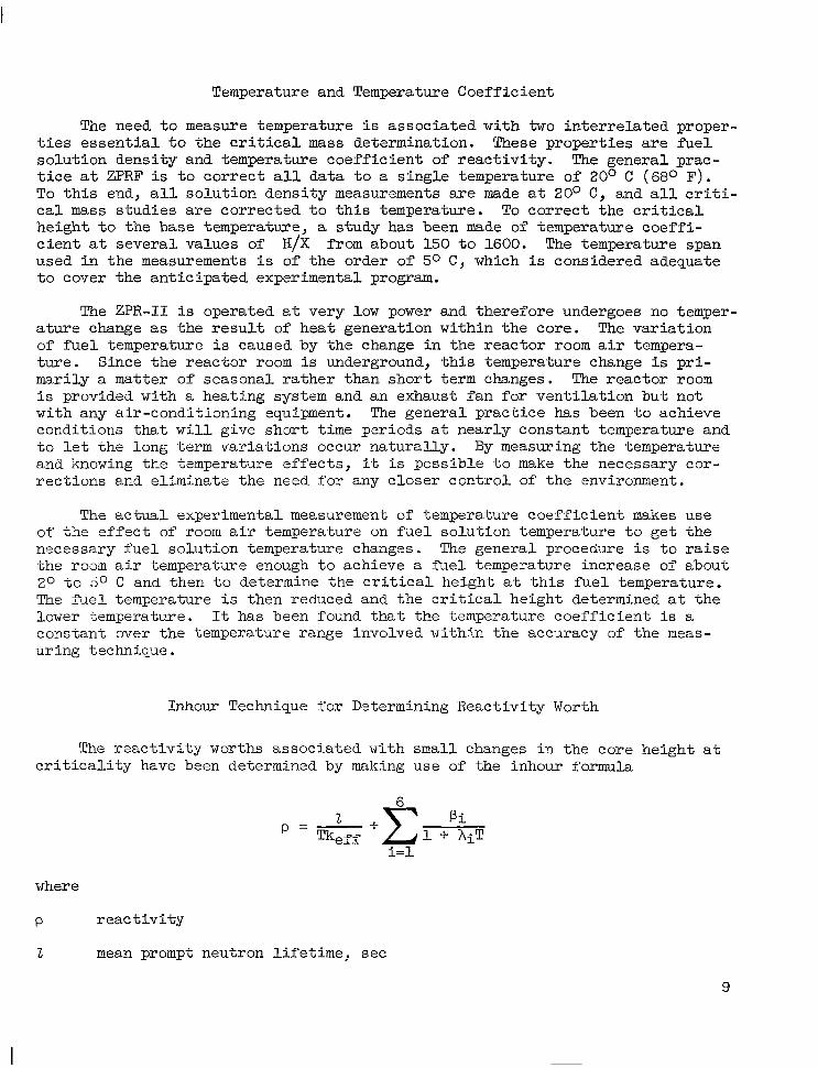
The react ivi ty worths associated with small changes in the core height a t c r i t i c a l i t y have been determined by making use of the inhour formula
where
P
2
r e a c t i v i t y
mean prompt neutron l ifetime, sec
9
T reactor period, sec
keff effect ive mult ipl icat ion factor
pi f r ac t ion o f t o t a l number of f ission neutrons belonging to ith delay group
Ai radioactive decay constant for that group, l/sec
The technique involves perturbing the s teady-state condi t ion of the c r i t i c a l system by a small amount and measuring the associated period. From th is per iod the r eac t iv i ty is determined by using the value 0.0064 for the delayed f rac- t i on p and the values for p i and A i reported in reference 5.
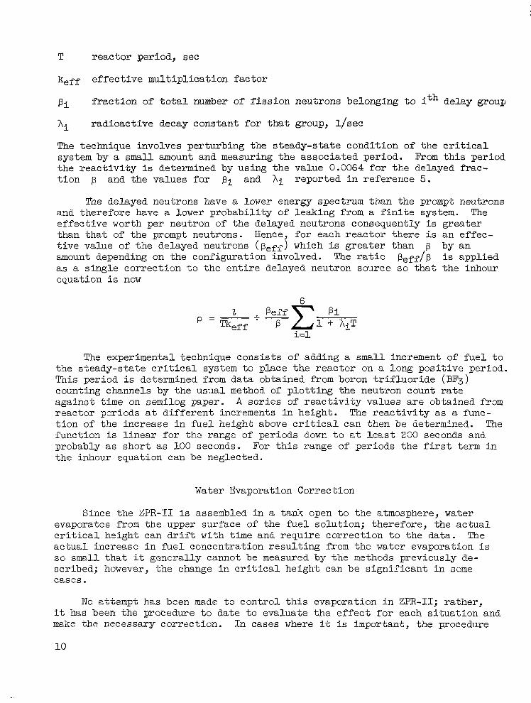
The delayed neutrons have a lower energy spectrum than the prompt neutrons and therefore have a lower probabi l i ty of leaking from a f i n i t e system. The effective worth per neutron of the delayed neutrons consequently is greater than that of the prompt neutrons. Hence, for each reactor there i s an effec- t ive value of the delayed neutrons (perf) which is greater than p by an amount depending on the configuration involved. The r a t i o pe f f /p i s applied as a single correction t o the entire delayed neutron source s o that the inhour equation i s now
The experimental technique consists of adding a small increment of f u e l t o the s teady-s ta te c r i t i ca l system t o place the reactor on a long positive period. This period i s determined from data obtained from boron t r i f l u o r i d e (BF3) counting channels by the usual method of plot t ing the neutron count ra te against time on semilog paper. A s e r i e s of react ivi ty values are obtained from reactor periods a t different increments in height. The r e a c t i v i t y a s a func- t ion of the increase in fuel height above c r i t i c a l can then be determined. The function is l inear for the range of periods down t o a t l e a s t 200 seconds and probably as short as 100 seconds. For t h i s range of periods the f i rs t term i n the inhour equation can be neglected.
Water Evaporation Correction
Since the ZPR-I1 is assembled i n a tank open t o t h e atmosphere, water evaporates from the upper surface of the fuel solution; therefore, the actual c r i t i ca l he ight can dr i f t with time and require correction to the data. The actual increase in fuel concentrat ion resul t ing from the water evaporation is s o small t ha t it generally cannot be measured by the methods previously de- scribed; however, the change in c r i t i ca l he igh t can be s ign i f i can t i n some cases.
No attempt has been made t o control t h i s evaporation in ZPR-11; ra ther , it has been the procedure t o d a t e t o evaluate the effect for each si tuation and make the necessary correction. In cases where it is important, the procedure
10
general ly resolves i tself in to running a s t anda rd c r i t i ca l ca se a t the begin- ning and end of the par t icu lar measurements and in to assuming that the change i n c r i t i c a l h e i g h t due to evaporat ion is a l inear funct ion of time during the experiment. Measurements requiring evaporation corrections usually are limited t o a s ingle work day.
Miscellaneous Reactivity Effects
Determining t h e a b s o l u t e c r i t i c a l mass i n a system such as the ZPR-I1 necessitates the consideration of the following small e f f ec t s : (I) neutron r e f l ec t ion due to the reactor tank, support stand structure, instrumentation chamber housing, and reactor room walls, ( 2 ) the nuclear effect of the reactor tank protective coating, ( 3 ) interact ion between f u e l i n the reactor tank and in the s torage tanks, and ( 4 ) f u e l i n f i l l and dump l ines ad j acen t t o t he bottom of the core.
The r e a c t i v i t y e f f e c t of neutron reflection from the support stand struc- t u r e and reactor room walls cannot be sat isfactor i ly determined but i s gener- a l l y considered to be negl igible . The worth of aluminum in the tank can be accounted f o r ana ly t ica l ly and has not been measured experimentally. The reac- t i v i t y worth of a sample of t he Gly-ptal coating has been experimentally measured i n ZPR-I as e s sen t i a l ly t ha t due to the displacement of f’uel. The in te rac t ion between f u e l i n t h e r e a c t o r and storage tank can be inferred from s o l i d angle calculat ions and has a l so been considered on the basis of past work t o be small enough t o be neglected. The one i tem that had not been evaluated in any manner previous t o th i s work was the reac t iv i ty e f fec t assoc ia ted wi th the fue l in the dump and f i l l l ines ad jacent to the bottom of the core. The e f f ec t w a s measured t o be worth a t most about 0.040 cent imeter in c r i t i ca l he ight . This e f fec t is not considered in the data reported since it involves a separate correction measurement for each concentration.
Most of the miscellaneous effects discussed are of l i t t le concern t o the research programs planned for ZPR-I1 because most of the experimental work i s of a na ture in which relative data are being determined. Any errors beyond the e r ror limits spec i f ied in the resu l t s should re f lec t a constant bias f’rom ef - fects present a t a l l times and not be of a random nature.
RESULTS AND DISCUSSION
The experimental data presented i n th i s r epor t i nc lude c r i t i ca l mass deter- minations, temperature coefficient measurements, and react ivi ty worth deter- minations carried out by using the NASA ZPR-11. The c r i t i c a l mass s tudies represent data obtained for uranyl fluoride solution systems with a d i f f e ren t geometry than previously reported. The other data are o f genera l in te res t for sa fe ty and operating considerations.
C r i t i c a l Mass Studies
C r i t i c a l mass determinations were made by using the ZPR-I1 f o r a range of
11
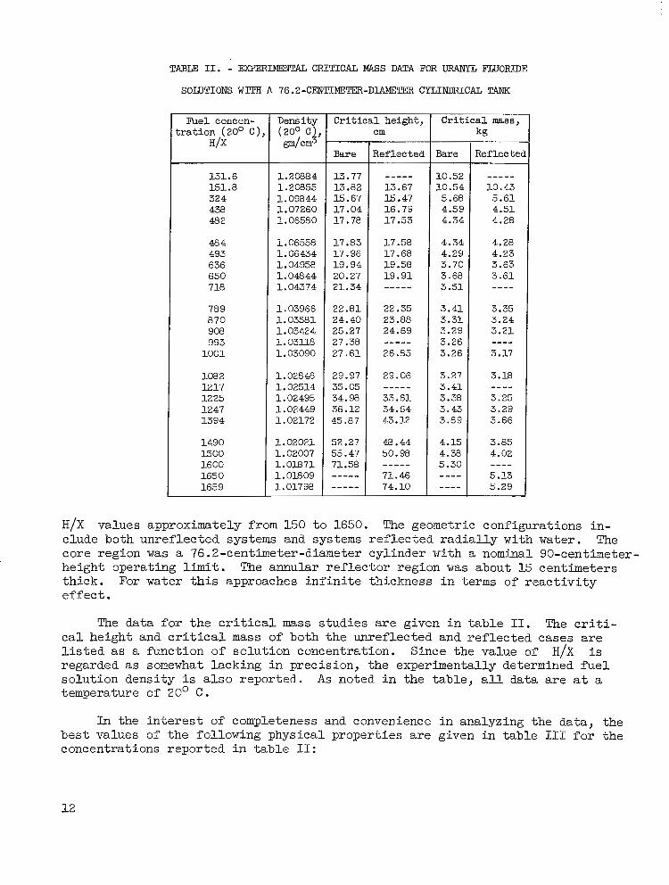
TABLE 11. - EXPERIMENTAL CRITICAL W S DATA FOR URANYL FWORIDE
SOLUTIONS W I T H A 76.2-CENTCMETEE-DIAM3TER CYLINDRICAL TANK
Fuel concen- t r a t i o n (20' c );
H I X
151.6 151.8 324 438 482
484 493 636 650 718
78 9 870 908 993 1001
1082 12 17 12 25 1247 1394
1490 1500 1600 165 0 1659
Density (200 c ) @lcm3
1.20884 1.20855 1.09844 1.07260 1.06580
1.06558 1.06434 1.04958 1.04844 1.04374
1.03966 1.03581 1.03424 1.03U8 1.03090
1.0284% 1.02514 1.02495 1.02449 1.02172
1.02021 1.02007 1.01871 1.01809 1.01798
7 C r i t i c a l h e i g h t ,
Bare
13.77 13.82 15.67 17.04 17.78
17.83 17.96 19.94 20.27 21.34
22.81 24.40 25.27 27.38 27.61
29.97 35.05 34.98 36.12 45.87
52.27 55.47 71.58 ""_ ""_
cm
Reflected
"_" 13.67 15.47 16.79 17.53
17.58 17.68 19.58 19.91 ""_ 22.35 23.88 24.69 "_" 26.85
29.06 "_" 33.61 34.64 43.12
48.44 50.98
71.46 74.10
""_
I I
Bare
10.52 10.54 5.68 4.59 4.34
4.34 4.29 3.70 3.68 3.51
3.41 3.31 3.29 3.26 3.26
3.27 3.41 3.38 3.43 3.89
4.15 4.38 5.30 ""
""
kg
Ref lec te ~~ - ~~~ ""_
10.43 5.61 4.51 4.28
4.28 4.23 3.63 3.61 ""
3.35 3.24 3.21
3.17
3.18
""
""
3.25 3.29 3.66
3.85 4.02
5.13 5.29
""
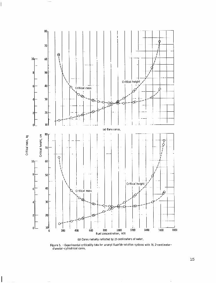
H/X values approximately from 150 to 1650. The geometric configurations in- clude both unreflected systems and systems reflected radially with water. The core region was a 76.2-centimeter-diameter cylinder with a nominal 90-centimeter- height operating limit. The annular reflector region was about 15 centimeters thick. For water this approaches infinite thickness in terms of reactivity effect.
The data for the critical mass studies are given in table 11. The criti- cal height and critical mass of both the unreflected and reflected cases are listed as a function of solution concentration. Since the value of H/X is regarded as sonewhat lacking in precision, the experimentally determined fuel solution density is also reported. As noted in the table, all data are at a temperature of 20' C.
In the interest of completeness and convenience in analyzing the data, the best values of the following physical properties are given in table 111 for the concentrations reported in table 11:
12
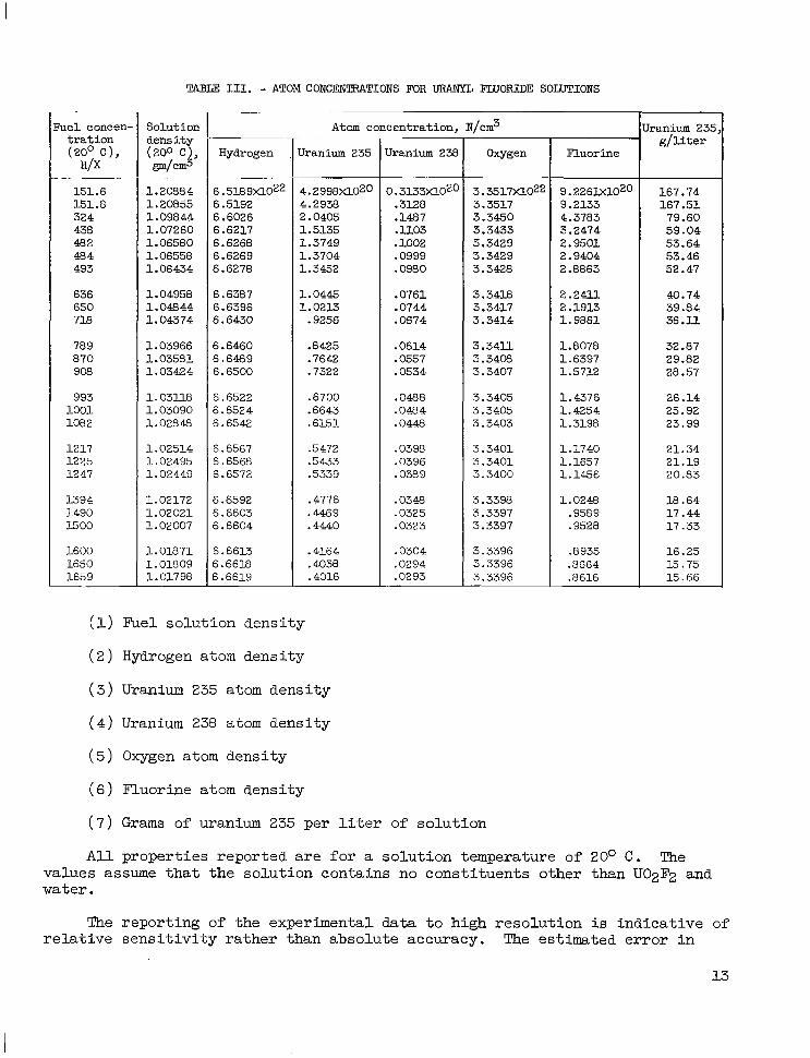
TABLE 111. - ATOM CONCENTRATIONS FOR URANYL FLUORIDE SOLUTIONS ~- ~~
h e 1 concen- t r a t i o n (20° c ) , H/X
151.6 151.8 324 438 482 484 493
636 650 738
789 a70 9oa
993 1001 108 2
1217 1225 12 47
1394 1490 15 00
1600 1650 1659
.~ ~~
Solution dens i ty (200 C), d c m 3
1.20884 1.20855 1.09844 1.07260
. ~~
1.06580 1.06558 1.06434
1.04958 1.04844 1.04374
1.03966 1.03581 1.03424
1 .03l l8 1.03090 1.02849
1.02514 1.02495 1.02449
1.02172 1.02021 1.02007
1.01871 1.01809 1.01798
T Atom concentration, N/crn3
Hydrogen Uranium 235 -1 ~
6.518 9x10²² 6.5192 6.6026 6.6217 6.6268 6.6269 6,6278
6.6381 6.6396 6.6430
6.6460 6.6489 6.6500
6.6522 6.6524 6.6542
6.6567 6.6568 6.6572
6.6592 6.6603 6.6604
~~ .~
4.2998Xl0Z0 4.2938 2.0405 1.5135 1.3749 1.3704 1.3452
1.0445 1.0213
.9256
.e425
.7642
.7322
.6700
.6643
.6151
.5 472
.5433
.5339
.4776
.4469
.4440
6.6613 .4164 6.6618 .4038 6.6619 .4016
Uranium 239
0. 3133)(1020 .3128 .1487 . U.03 .lo02 .0999 .0980
.0761
.0744
.0674
.0614
.055 7
.0534
.0488
.0484
.044%
.0398
.0396
.038 9
.0348
.0325
.0323
.0304
.0294
.0293 ~~~
Oxygen
3. 3517X1022 3.3517 3.3450 3.3433 3,3429 3.3429 3.3428
3,3418 3.3417 3.3414
3 .34 l l 3.3408 3.3407
3,3405 3.3405 3.3403
3.3401 3.3401 3.3400
3.3398 3.3397 3.3397
3.3396 3.3396 3.3396
~~ ~
Fluorine
9. 2261X1020 9.2133 4.3783 3.2474 2.9501 2.9404 2 .E863
2 .24l l 2 .1913 1.9861
1.8078 1.6397 1.5712
1.4376 1.4254 1.3198
1.1740 1.1657 1.1456
1.0249 .9589 .9528
.8 935 .e664 .E616
Jranium 235 g / l i t e r
167.74 167.51
79.60 59.04 53.64 53.46 52.47
40.74
36 .U. 32.87 29.82 28.57
26.14 25.92 23.99
21.34 21.19
39.84
20.83
18.64 17.44 17.33
16.25 15 .75 15.66
(1) Fuel solution density
(2) Hydrogen atom density
(3) Uranium 235 atom density
( 4 ) Uranium 238 atom density
( 5 ) Oxygen atom density
(6) Fluorine atom density
(7) Grams of uranium 235 per liter of solution
A l l properties reported are for a solution temperature of 20° C. The values assume that the solution contains no constituents other than U02F2 and water.
The reporting of the experimental data to high resolution is indicative of relative sensitivity rather than absolute accuracy. The estimated error in
13
c r i t i c a l mass var ies from about 0.5 percent a t an H/X of 150 t o 1.5 percent a t an H/X of 1500. It i s e s t ima ted t ha t t he abso lu t e c r i t i ca l he igh t has er ror limits of k0.075 cent imeter a t t r ibu tab le l a rge ly to dimension tolerances. The c r i t i c a l h e i g h t s r e l a t i v e t o e a c h o t h e r a r e f e l t t o be i n e r r o r by no more than k0.025 centimeter, which implies that a small constant bias error i n t h e c r i t i c a l h e i g h t due to reactor vessel d imensional tolerances could exis t . The measurement of so lu t ion dens i ty is accurate (95 percent confidence limit) t o L-0.00025 gram per cubic centimeter a t a l l dens i t ies . Thus d i f f e ren t e r ro r limits w i l l be obtained for the H/X va lues and c r i t i ca l mass values depending on the concentration. For example, an error limit of +0.00025 in dens i ty cor re- sponds to va lues of H/X of 150.0k0.2, 500k2, 1000k8, or 1600k20.
These limits a r e borne out i n gene ra l by the reproducibil i ty achieved during the studies. For example, a l though the da ta l i s ted a t va lues of H/X of 151.6 and 151.8 were obtained a t a difference in time of 6 months and in- volved s ignif icant ly different fuel temperature correct ions, they are s t i l l i n good agreement. The data a t several other values of H/X such as 482 and 484 are also separated in t ime and temperature. These data are no t in as good agreement but a re wi th in the e r ror limits.
The data of t he ba re c r i t i ca l he igh t s and c r i t i c a l masses a re p lo t t ed as a function of fue l concent ra t ion in f igure 5 (a) . S imi la r ly , the da ta for the re f lec ted cases a re p lo t ted in f igure 5 (b) . It i s of i n t e re s t t o no te that the minimum c r i t i c a l mass i s found a t about a value of H/X of 1000 f o r both the bare and reflected systems.
Temperature Coefficient
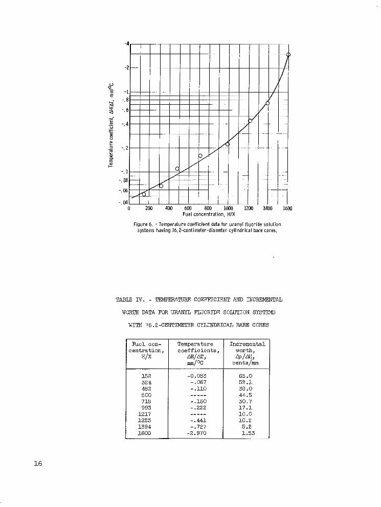
The temperature coefficient has been measured over the range of H/X from about 150 t o 1600 although not for a l l the concentrations run. This measure- ment i s time consuming and in many cases approaches the limit of reso lu t ion in the reactivity measuring technique. It i s the re fo re d i f f i cu l t t o a s s ign e r ro r limits t o the da ta tha t a re somewhat l imited. The estimated error in these data i s +20 percent although the data when p lo t t ed ( s ee f i g . 6 ) appear t o f a l l more c lose ly t han t ha t t o t he f i t t ed cu rve . These data a lso are tabulated in t ab le IV. The negative sign is used because an increase in temperature results i n a loss in r eac t iv i ty . The values used t o make the co r rec t ions i n t he c r i t i - c a l mss data were taken from the curve in f igure 6 and not from the individual data points.
The temperature cozfficient data reported have been limited t o bare systems. Enough experimental data for reflected systems have been obtained, however, t o observe that an approximate correlation of the temperature effect as a function of c r i t i c a l h e i g h t e x i s t s between the bare and reflected systems. This correlation is used, therefore, f o r the temperature correction of the ref lected data .
To make the tmpera ture coef f ic ien t more universal ly appl icable it i s reported also i n terms of r e a c t i v i t y i n f i g u r e 7. To do t h i s , it is necessary t o make use of the incremental reactivity worth data described in the next section. The product of temperature coefficient in terms of AH/m and the
14
80
70
60
M
40
?u
20
10
I
@ I I \ \ \ \
\ \
. . ”
0’” s 200
\ \ \
~~
”
\ \ \
”
Cri t i ca
/
P ’ /
.”-
”
mass
(a) Bare cores
I 60 -
-
50 - ”
40
-
N -
20 - .
1oc 0
/
Cri t ical height ,I’
”
1200 1400
-1: 43:
loo0
-. ”
?< .,
30( Fuel concentration, HIX
(b) Cores radially reflected by 15 centimeters of water.
7 !
400 600 1600 1800
F igu re 5. - Exper imental cr i t ical i ty data for uranyl f luor ide solut ion systems wi th 76.2-cent imeter- diameter-cyl indrical cores.
15
u 1200 1400 1
Fuel concentration, HIX
Figure 6. - Temperature coefficient data for uranyl fluoride solution systems having 76.2-centimeter-diameter cylindrical bare cores.
TABLE N. - TEMPERATLTRF COEFFICIENT AND INCRFMENTAL
WORTH D " N FOR URANYL FLUORIDE SOLUTION SYSTEMS
W I T H 76.2-CENTIMETER CYLINDRICAL BARE CORES
Fuel con- c e n t r a t i o n ,
H/X
Temperature c o e f f i c i e n t s ,
fwm, m / O C
Incremental worth, @/f%
cents/mm
152 32 4 482 500 718 993
1217 1225 1394 1600
-0.053 - .067 - . llo - .160 - .222
- .441 -. 727 -2.970
"_"
_""
65.0 5 2 . 1 38 .O 44.5 30.7 1 7 . 1 10.0 10.2 5.2 1.53
16
Fuel concentration, HIX
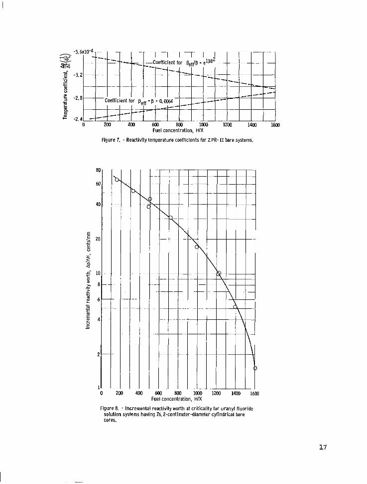
Figure 7. - Reactivity temperature coefficients for ZPR- I1 bare systems.
1Mx) M 1400 1600
Fuel concentration, HIX
Figure 8. - Incremental reactivity worth at criticality for uranyl fluoride solution systems having 76.2-centimeter-diameter cylindrical bare cores.
17
incremental reactivity worth &/AH gives the temperature coefficient in terms of &/AT.
The lower curve of figure 7 is a plot of react ivi ty worth per OC against H/X, which was obtained by taking the product of the values from the curves in f igures 6 and 8 and applying the appropriate conversion factor. Multiplying the reactivity values expressed in cents by the delayed neutron fraction 0.0064 yields the react ivi ty worth in terms of the e f fec t ive mul t ip l ica t ion f ac to r fo r a peff of 0.0064. The data follow a s t r a igh t l i ne w i th in t he e r ro r limits described.
The upper curve i n f i g u r e 7 is obtained by using a calculated value of the effective delayed neutron fraction rather than 0.0064 a t each fuel concentra- t ion . The r a t i o of Peff/P f o r the ZPR systems is approximated by exp(13B2), where the B2 used in th i s case is the geometric buckling obtained from the dimensions of t he ba re c r i t i ca l systems. This calculational method is similar t o t h e method described in reference 6. The coef f ic ien t of 13 has been derived by applying this method t o unpublished experimental data for perf measured with the ZPR-I system. It should be noted that more precise values of perf are not essent ia l to this s tudy, because the pr imary object ive i s t o show the typ ica l t rend of the data. The curves in f igure 7 a r e dashed t o show that they should not be used for working curves.
The p r inc ip l e e f f ec t t o be noted from f igure 7 is the re la t ive ly cons tan t react ivi ty values for the temperature coeff ic ient that were found f o r t h i s range of fuel concentration studies. The value for temperature coefficient appears t o be of the order of 3 ~ 1 0 ~ ~ i n 4 per OC f o r ZPR- I1 systems. This value is i n good agreement with unreported data obtained for the ZPR-I system over a range of H/X from about 300 t o 550.
Reactivity Worth Measurements
In determining the react ivi ty inser t ion ra tes a t c r i t i c a l i t y or the reac- t i v i t y worth a t c r i t i c a l i t y of a smal l per turba t ion to a c r i t i c a l system, it i s des i rab le to have a convenient method t o measure the e f fec t . For solut ion c r i t i ca l s i n cy l ind r i ca l t anks , t he most convenient parameter is cylinder height, which has been calibrated in the ZPR-I1 to g ive va lues for reac t iv i ty worth per unit increase in fuel height a t c r i t i ca l i ty for bare sys tems. The un i t s of react ivi ty are cents based on the use of p = 0.0064 in the inhour equations; however, for the reactor per iods involved in the measurements reported herein, the react ivi ty in cents is independent of the value of p t ha t i s used. The periods are long enough that the prompt term in the inhour equa- tion approaches zero and can be neglected. Thus, a u n i t of cents represents 1 percent of p regardless of what the value of the delayed f ract ion actual ly is .
The data on incremental reactivity worths a t c r i t i c a l i t y as a function of fuel concentrat ion are plot ted in f igure 8 and given in t he t h i rd column of t ab le N. These data are the compilation of measurements made over a la rge period of time and are not necessarily indicative of the bes t va lues tha t would be possible with present capabili ty. No e r ror limits are given, but it is f e l t
18
t ha t t he cmve fit of the da ta i s a good representation of the values involved and that the accuracy is quite adequate for the purposes of t h i s r e p o r t .
L e w i s Research Center, National Aeronautics and Space Administration,
Cleveland, Ohio, August 18, 1965.
1. Beck, C. K.; Callihan, A. Dixon; Morfit t , J. W.; and Murray, Raymond L.: C r i t i c a l Mass Studies . P t 111. Rep. K-343, K-25 Plant, Carbide and Carbon Chemicals Corp., Apr. 19, 1949.
2 . Fox, J. K.; Gilley, L. W . ; and Callihan, D . : C r i t i c a l Mass Studies. P t I X . Aqueous U-235 Solutions. Rep. ORNL-2367, Oak R i d g e Nat. Lab. Mar. 4, 1958.
3. Day, H . 0 . : Physical Propert ies . The U02F2 - Hz0 System. Propert ies of Aqueous Solution Systems. Engineering, vol. 2 of Reactor Handbook, J. F. Hogerton and R . C . Grass, eds. Rep. AECD-3646, AEC, May 1955,, pp. 585-593.
4. Scott, Wilfred W . , ed.: Standard Methods of Chemical Analysis. Fifth ed. , N . Howell Furman, ed. , vol. 1, D. Van Nostrand Co., Inc ., 1939, p. 1022.
5. Keepin, G . R . ; Wimett, T. F.; and Zeigler, R . K . : Delayed Neutrons from Fissionable Isotopes of Uranium, Plutonium and Thorium. Phys. Rev., vol. 107, no. 4, Aug. 1957, pp. 1044-1049.
6 . Gwin, R . ; Trubey, D. K. ; and Weinberg, A . M.: Experimental and Theoretical Studies of Unreflected Aqueous U-235 C r i t i c a l Assemblies. Reactor Physics. Vol. 1 2 of Proc. of the Second United Nations Conf. on Peaceful Uses of Atomic Energy, United Nations, 1958, pp. 529-538.
NASA-Langley, 1965 E-3025
I ~~ -. ~~
19
“The aeronautical and space activities of the United States shall be conducted so as to contribute . . . to the expansion of hrman knowl- edge of phenomena in the atmosphere and space. The Administration shall provide for the widest practicable and appropriate dissetnination of information concernilzg its activities and the results ther.eof.”
“ N A T I O N A L AERONAUTICS A N D SPACE ACT OF 1958
NASA SCIENTIFIC AND TECHNICAL PUBLICATIONS
TECHNICAL REPORTS: Scientific and technical information considered important, complete, and a lasting contribution to existing knowledge.
TECHNICAL NOTES: Information less broad in scope but nevertheless of importance as a contribution to existing knowledge.
TECHNICAL MEMORANDUMS: Information receiving limited distri- bution because of preliminary data, security classification, or other reasons.
CONTRACTOR REPORTS: Technical information generated in con- nection with a NASA contract or grant and released under NASA auspices.
TECHNICAL TRANSLATIONS: Information published in a foreign language considered to merit NASA distribution in English.
TECHNICAL REPRINTS: Information derived from NASA activities and initially published in the form of journal articles.
SPECIAL PUBLICATIONS: Information derived from or of value to NASA activities but not necessarily reporting the results -of individual NASA-programmed scientific efforts. Publications indude conference proceedings, monographs, data compilations, handbooks, sourcebooks, and special bibliographies.
Details on the availability of these publications may be obtained from:
SCIENTIFIC AND TECHNICAL INFORMATION DIVISION
NATIONAL AERONAUTICS AND SPACE ADMINISTRATION
Washington, D.C. PO546