i-8091 2-axis stepping/servo motor control card user manual · pdf filei-8091 2-axis...
TRANSCRIPT

I-8091 User Manual Version 2.0 04/2003
I-8091
2-axis stepping/servo motor control card
User Manual
Version 1.0 06/2001 Edition
Warranty: All products manufactured by ICP DAS are warranted against defective materials for one year from the date of delivery to the original purchaser Warning: ICP DAS assumes no liability for damage consequent to the use of this product. ICP DAS reserves the right to change this manual at any time without notice. The information furnished by ICP DAS is believed to be accurate and reliable. However, no responsibility is assumed by ICP DAS for it’s use, nor for any infringements of patents or other rights of third parties resulting from it’s use. Copyright Copyright 2001 by ICP DAS. All right are reserved Trademark The names used for identification only maybe registered trademarks of their respective companies.
http://www.icpdas.com 2-1 ICPDAS

I-8091 User Manual Version 2.0 04/2003
I-8091 2-axis Stepping/Servo Motor Control Card
The I-8091 card is a 2-axis command-type stepping motor control card
on I-8000 platform, it also can be used as servo motor control (pulse input
type). This card has an embedded CPU which performs motion commands
transfered from I-8000 main system to increase the system performance. A
2Kbytes-FIFO is introduced as command buffer. This buffer can provide over
700ms buffer time.
A system including I-8000(main system), I-8091(2-axis stepping/servo control card), I-8090(3-axis encoder card) can be implemented as a stand along motion controller system for low cost automatical machine.
Features I-8000 series.
2-axis independent, simultaneous stepping motor control / servo motor
control (pulse input type).
Maximum pulse rate: 1Mpps.
Maximum step counts: steps. 232 −1
DOS driver.
embedded CPU.
command type interface.
2-axis linear, 2-axis circular interpolation.
automatic trapezoidal acceleration / deceleration.
output pulse modes : CW/CCW or pulse/direction.
output polarity can be programmable.
2500Vrms optical isolated signal output.
3 optical isolated digital inputs per axis for limit switches.
programmable limit switch initial condition as normal open(N.O.) or normal
close(N.C.).
http://www.icpdas.com 2-2 ICPDAS

I-8091 User Manual Version 2.0 04/2003
I-8091 Contents _ 1. Introduction 2-4
1.1 System Block Diagram 2-4
1.2 DDA technology 2-5
2. Hardware 2-8
2.1 I-8000 hardware address 2-8
2.2 Register of I-8091 board 2-9
2.3 LED indicator 2-10
2.4 Hardware configuration 2-11
2.4.1 Limit switch configuration 2-11
2.4.2 Output pulse mode configuration 2-12
2.4.3 Direction configuration 2-12
2.4.4 Turn Servo ON/OFF (Hold ON/OFF) 2-12
2.4.5 Automatic protection 2-12
2.4.6 Set limit switch as normal close condition 2-13
2.5 Connection 2-14
2.5.1 Pin assignment of connector CN2 2-14
2.5.2 The internal circuit of CW_PULSE, CCW_DIR, HOLD 2-15
2.5.3 The internal circuit of limit switch input 2-15
2.5.4 Example of connection 2-16
3. Software 2-18
3.1 Functions 2-18
3.1.1 Setting commands 2-20
3.1.2 Stop commands 2-24
3.1.3 Simple motion commands 2-25
3.1.4 Interpolation commands 2-30
3.1.5 Others 2-35
3.2 Start up and end of program 2-37
4. Example 2-39
4.1 Detect I-8091 card 2-39
4.2 Example: DEMO.cpp 2-40
4.3 Example: DEMO1.cpp 2-40
http://www.icpdas.com 2-3 ICPDAS

I-8091 User Manual Version 2.0 04/2003
1. Introduction _
1.1 System Block Diagram The I-8091 stepping motor control card is a micro-computer controlled, 2-axis
pulse generation card. It includes a 2Kbytes-FIFO to receive motion command
from host, a micro-computer for profile generation and protection, 2-axis DDA
chip to execute DDA function when interpolation command is used, 2500Vrms
optical isolation inserted for industrial application.
2K FIFO
Interface
CPU DDA Chip
X-axis
DDA Chip
Y-axis
OpticalIsolation
Limit Switch
Input Port
ConnectorLimit Switch Signal
Profile Generation
Protection
Limit Switch
Input Port
Bus
Fig.(1) block diagram of I-8091 card
http://www.icpdas.com 2-4 ICPDAS

I-8091 User Manual Version 2.0 04/2003
1.2 DDA Technology The DDA chip is the heart of I-8091 card, it will generate equal-space
pulse train corresponding to specific pulse number during a DDA period. This mechanism is very useful to execute pulse generation and interpolation function. The DDA period can be determined by DDA cycle. Table(1) shows the relation among DDA cycle, DDA period and output pulse rate. When DDA cycle set to 1, the DDA period is equal to (1+1)x1.024ms = 2.048ms. The output pulse number can be set to 0~2047, therefore the maximum output pulse rate will be 1Mpps. The minimum output pulse rate is 3.83pps when set DDA cycle=254 (DDA period = (254+1)x1.024ms = 261.12ms).
DDA period
Z pulse = 4
Y pulse = 6
X pulse = 3
DDA cycle
Fig.(2) DDA mechanism
Table(1) The Relation among DDA cycle, DDA period and output pulse rate. DDA cycle DDA period Max. pulse
rate(n=2047) Min. pulse rate (n=1)
1 2.048ms 999511pps 488pps 2 3.072ms 666341pps 325pps 3 4.096ms . . . . . . N (N+1)*1.024ms 2047/(DDA period) 1/(DDA period) . . . .
254 261.12ms 7839pps 3.83pps The DDA cycle can be set by i8091_SET_VAR() command which decribed in charpter 3. The selection criterion of DDA cycle was described as following.
http://www.icpdas.com 2-5 ICPDAS

I-8091 User Manual Version 2.0 04/2003
(1) The required max. output pulse rate.
PRmax = Vmax*N/60
PRmax = 2047
1 1 024* .DDAcycle ms+( ) PRmax : max. output pulse rate. Vmax : max. speed (rpm). N : the pulse number of stepping motor per revolution. (pulse/rev).
2. The required speed resolution. The maximum output pulse number is Np(0~2047), therefore the speed resolution is Vmax(max. speed)/Np. The DDA cycle can be obtained by following equation.
PRmax = Np
DDAcycle ms* .+1 1 024( )
3. When choose large DDA cycle (DDA period), it will occur vibration between different pulse input which generally can be observed during acceleration or deceleration. So, the small DDA cycle , the smooth acceleration/deceleration curve as long as the speed resolution is acceptable.
Example: Stepping Motor The specification of stepping motor is 500 pulse/rev, max. speed 500 rpm, speed resolution 2 rpm. The required max. pulse rate
PRmax = 500 rpm*500/60 = 4166.67 pps The maximum output pulse
Np = 500rpm/2rpm =250 pulse number The DDA cycle can be calculated by follow equation
PRmax = Np
DDAcycle ms* .+1 1 024( )
4166.67 = 250
1 1 024* .DDAcycle ms+( ) DDA cycle = 58
http://www.icpdas.com 2-6 ICPDAS

I-8091 User Manual Version 2.0 04/2003
High Speed = 247 pulse (4166.67*58*0.001024) The above results means that maximum speed is 500rpm when send command i8091_SET_VAR(0, 58, 2, 2, 247) to I-8091 card.
Example: Pulse type input Servo Motor
The specification of servo motor is 8000 pulse/rev, max. speed 3000 rpm, speed resolution 2 rpm. The required max. pulse rate
PRmax = 3000 rpm*8000/60 = 400,000 pps The maximum output pulse
Np = 3000rpm/2rpm =1500 pulse number The DDA cycle can be calculated by follow equation
PRmax = Np
DDAcycle ms* .+1 1 024( )
400,000 = 1500
1 1 024* .DDAcycle ms+( ) DDA cycle = 3 High Speed = 1638 pulse (400,000*4*0.001024)
The above results means that maximum speed is 3000rpm when send command i8091_SET_VAR(0, 3, 2, 2, 1638) to I-8091 card.
http://www.icpdas.com 2-7 ICPDAS

I-8091 User Manual Version 2.0 04/2003
2 Hardware _ 2.1 I-8000 hardware address
The hardware address of I-8000 main system is fixed as following table. There are 4 slots I-8000 and 8 slots I-8000.
Slot 1 Slot 2 Slot 3 Slot 4 Slot 5 Slot 6 Slot 7 Slot 8 I-8000, 4 slot address
0x080 0x0A0 0x0C0 0x0E0 --- --- --- ---
I-8000, 8 slot address
0x080 0x0A0 0x0C0 0x0E0 0x140 0x160 0x180 0x1A0
Slot 1 Slot 2 Slot 3 Slot 4
Slot 8 Slot 7 Slot 6 Slot 5 Slot 4 Slot 3 Slot 2 Slot 1
88888
88888
I-8000, 4 slots
I-8000, 8 slots
Fig.(3) I-8000 hardware address
http://www.icpdas.com 2-8 ICPDAS

I-8091 User Manual Version 2.0 04/2003
2.2 Registers of I-8091 board
The I-8091 card’s registers table as following.
Register Add. R/W Bit 7 Bit 6 Bit 5 Bit 4 Bit 3 Bit 2 Bit 1 Bit 0 ID 0x00 R 0x0E LIMIT1 0x01 R /EMG /FFFF /FFEF /LS14 /LS11 /ORG1 LIMIT2 0x02 R /YSTOP /XSTOP /LS24 /LS21 /ORG2 WRFF 0x01 W Command port RSTFF 0x02 W Reset FIFO
Register Add. R/W Bit 7 Bit 6 Bit 5 Bit 4 Bit 3 Bit 2 Bit 1 Bit 0 ID 0x00 R 0x0E The ID register is read only and its value is fixed as 0x0E. User can check this register to identify I-8091 card or not.
Register Add. R/W Bit 7 Bit 6 Bit 5 Bit 4 Bit 3 Bit 2 Bit 1 Bit 0 LIMIT1 0x01 R /EMG /FFFF /FFEF /LS14 /LS11 /ORG1 /ORG1 : original point limit switch of X-axis.
/LS11, /LS14 : limit switches of X-axis, which must be configured as chapter
2.4.1.
/EMG : emergency switch.
/FFEF : active low, indicate FIFO is empty.
/FFFF : active low, indicate FIFO is full.
Register Add. R/W Bit 7 Bit 6 Bit 5 Bit 4 Bit 3 Bit 2 Bit 1 Bit 0 LIMIT2 0x02 R /YSTOP /XSTOP /LS24 /LS21 /ORG2 /ORG2 : original point switch of Y-axis.
/LS21, /LS24 : limit switches of Y-axis, which must be configured as chapter
2.4.1.
/XSTOP, /YSTOP : These signals indicate the operating situation of X, Y axis
in CPU.
1 : busy, 0 : stop
The commands i8091_WAIT_X( ) and i8091_WAIT_Y( ) just to waiting for
http://www.icpdas.com 2-9 ICPDAS

I-8091 User Manual Version 2.0 04/2003
'/XSTOP' or '/YSTOP' signal become to '0'.
Register Add. R/W Bit 7 Bit 6 Bit 5 Bit 4 Bit 3 Bit 2 Bit 1 Bit 0 WRFF 0x01 W Command port I-8091 driver will send motion command by way of this register. Please do not
use this register to write any thing, or I-8091 will not operate properly.
Register Add. R/W Bit 7 Bit 6 Bit 5 Bit 4 Bit 3 Bit 2 Bit 1 Bit 0 RSTFF 0x02 W Reset FIFO This register is used to reset FIFO for clear all of commands pending in the FIFO buffer.
2.3 LED Indicator
power
/EMG /LS21 /LS24 /ORG2 /LS14 /LS11 /ORG1
Fig.(4) I-8091 LED indicator Where
/ORG1: X-axis’s original limit switch for machine home position.
/LS11, /LS14 : X-axis’s negative and positive limit switches.
/ORG2: Y-axis’s original limit switch for machine home position.
/LS21, /LS24 : Y-axis’s negative and positive limit switches.
/EMG : system’s emergency signal input.
http://www.icpdas.com 2-10 ICPDAS

I-8091 User Manual Version 2.0 04/2003
2.4 Hardware Configuration 2.4.1 Limit switch configuration
Because the profile generation and protection is executed by the CPU
on I-8091 card, the limit switches must configure as following diagram.
The motion command just can work properly.
LS11 ORG1 LS14
CW/FWCCW/BW
Motor
EXT_GND
/LS11
/LS14
/ORG1
X axis/EMG
Emergency
ccm
Fig.(5) Limit switch configuration of X axis
LS21 ORG2 LS24
CW/FWCCW/BW
Motor
EXT_GND
/LS21
/LS24
/ORG2
Y axis
ccm
Fig.(6) Limit switch configuration of Y axis
http://www.icpdas.com 2-11 ICPDAS

I-8091 User Manual Version 2.0 04/2003
2.4.2 Output pulse mode configuration I-8091 card provide two kind output method.
(a) CW/CCW mode
(b) Pulse/Direction mode
The command i8091_SET_MODE(cardNo, modeX, modeY) provide
parameters CW_CCW (0) and PULSE_DIR (1) to define output pulse
mode.
CW
CCW
Pulse
DirectionMode = 1 (PULSE_DIR)
Mode = 0 (CW_CCW)
Fig.(7) Output pulse mode
2.4.3 Direction configuration Sometimes, the output direction of X-axis, Y-axis is not in the
desired direction due to the motor’s connection or gear train. It is recommended to unify the output direction as shown in Figure(5)(6). The CW/FW direction is defined as toward outside from motor and the CCW/BW direction is defined as toward inside to motor. The i8091_SET_DEFDIR(cardNo, defdirX, defdirY) command provides parameters NORMAL_DIR (0) and REVERSE_DIR (1) to define the rotating direction of motor.
2.4.4 Turn Servo ON/OFF (Hold ON/OFF) To turn servo motor into servo ON(OFF) state, or turn stepping motor
into hold ON(OFF) state, the command i8091_SET_SERVO_ON(cardNo,
sonX, sonY) provide parameters ON (1) and OFF (0) to turn ON or OFF.
2.4.5 Automatic protection The I-8091 card has a automatic protected system.
(a) If X-aixs command is executing and moving toward CW/FW direction,
http://www.icpdas.com 2-12 ICPDAS

I-8091 User Manual Version 2.0 04/2003
X-axis will immediately stop when LS14 is touched. To release this
protection as long as X-axis move toward CCW/BW direction.
(b) If X-aixs command is executing and moving toward CCW/BW
direction, X-axis will immediately stop when LS11 is touched. To
release this protection as long as X-axis move toward CW/FW
direction.
(c) If Y-aixs command is executing and moving toward CW/FW direction,
Y-axis will immediately stop when LS24 is touched. To release this
protection as long as Y-axis move toward CCW/BW direction.
(d) If Y-aixs command is executing and moving toward CCW/BW
direction, Y-axis will immediately stop when LS21 is touched. To
release this protection, as long as Y-axis move toward CW/FW
direction.
(e) If the signal of the emergency limit switch /EMG was found in CPU
firmware, all motion will be terminated and stop.
2.4.6 Set limit switch as normal close condition The limit switches /EMG, /LS11, /LS14, /LS21, /LS24, /ORG1, /ORG2 is
initially normal open condition, that is, these signal is active when
connect it to ground. In industrial application, it might be recommended
normal close condition, that is, these signal is active when open from
ground.
The i8091_SET_NC(cardNo, sw) command can be set sw=0 (default), for
normal open condition. When set sw=1, for normal close condition.
http://www.icpdas.com 2-13 ICPDAS

I-8091 User Manual Version 2.0 04/2003
2.5 Connection 2.5.1 Pin assignment of connector CN2
EXT_GND
EXT_VCC (12~24V)
GND
+5V
CN2DB25M-90
1325122411231022
921
820
719
618
517
416
315
214
1
LS24
ORG2
CCW_DIR2
CW_PULSE2CW_PULSE1
LS14
HOLD1
LS21LS11
HOLD2
EMG
CCW_DIR1
ORG1
Fig.(8) CN2 connector
Table of CN2 connector’s pin assignment pin name pin
number Description
+5V 1 Internal +5V power, Max. output current: 50mA CW_PULSE1 2 X-axis CW (Pulse) output pin CCW_DIR1 3 X-axis CCW (Direction) output pin
HOLD1 4 X-axis HOLD (servo on) output pin GND 5 Signal ground of pin 2,3,4
EXT_VCC 6 External power(12~24V) for limit switches /ORG1 7 X-axis original (home) limit switch /LS11 8 X-axis limit switch
9,10 No used /LS14 11 X-axis limit switch /EMG 12 Emergency input
EXT_GND 13 External ground for limit switch +5V 14 Internal +5V power, Max. output current: 50mA
CW_PULSE2 15 Y-axis CW (Pulse) output pin CCW_DIR2 16 Y-axis CCW (Direction) output pin
HOLD2 17 Y-axis HOLD (servo on) output pin GND 18 Signal ground of pin 15,16,17
http://www.icpdas.com 2-14 ICPDAS

I-8091 User Manual Version 2.0 04/2003
EXT_VCC 19 External power(12~24V) for limit switches /ORG2 20 Y-axis original (home) limit switch /LS21 21 Y-axis limit switch
22,23 No used /LS24 24 Y-axis limit switch
EXT_GND 25 External ground for limit switch
2.5.2 The internal circuit of CW_PULSE, CCW_DIR, HOLD When output these signal as 1, it can source 15mA(max.).
When output these signal as 0, it can sink 50mA(max.)
+5V
330CW_PULSE1CCW_DIR1HOLD1CW_PULSE2CCW_DIR2HOLD2
i8091
Fig.(9) internal circuit of pulse output pin
2.5.3 The internal circuit of limit switch input Initially, the limit switch inputs of I-8091 board are normal open (N.O.),
the I-8091 board will automatic protect when limit switch pin connect
to EXT_GND. The user can use the command i8091_SET_NC
(cardNo, YES) to let those limit switch input as normal close condition
at the beginning of the user’s program.
EXT_VCC (12V~24V)
4.7K
/ORG1, /LS11, /LS14
/ORG2, /LS21, /LS24
/EMG
i8091
Fig.(10) internal circuit of limit switch input pin
http://www.icpdas.com 2-15 ICPDAS

I-8091 User Manual Version 2.0 04/2003
2.5.4 Example of connection
FAN-OUT TYPE (VEXTA) DRIVER
+5V
+5V
+5V
DGND
HOLD1
CW_PULSE1
CCW_DIR1
GND
CW +
CW -
CCW +
CCW -
HOLD +
HOLD -
654
1
3
654
1
3
654
1
3
1 4
2 3
1 4
2 3
1 4
2 3
Fig.(11) fan-out type driver (VEXTA's motor driver)
SINK TYPE DRIVERDGND
+5V
+5V
+5V
GND
CCW_DIR1
HOLD1
CW_PULSE1
COM
CW/PULSE
CCW/DIR
HOLD
654
1
3
1 4
2 3
654
1
3
654
1
3
1 4
2 3
1 4
2 3
Fig.(12) Sink type driver
http://www.icpdas.com 2-16 ICPDAS

I-8091 User Manual Version 2.0 04/2003
(12V~24V)
S8090 cardS8091 card
EXT_VCC
PHOME1
PLS24
PHOME2
PLS14
PLS21
PEMG
PLS11
CN2DB25M-90
13251224112310229
218
207
196
185
174
163
152
141
CN2DB25M-90
13251224112310229
218
207
196
185
174
163
152
141
2B-
3B-
3A+
1A-
2C-
EGND
3B+
2C+
2A+
E5V
3A-
2B+
3C-3C+
2A-
E5V
EGND
E5V
EXT_GND
EXT_VCC
S5V
SGND
CW_PULSE2CCW_DIR1
EGND
1A+
CW_PULSE1 1B+
CCW_DIR2
EGND
1B-
1C-1C+
HOLD1HOLD2
Fig.(13) The connection between I-8090 and I-8091 for function testing or
pulse feedback by I-8090 encoder card.
http://www.icpdas.com 2-17 ICPDAS

I-8091 User Manual Version 2.0 04/2003
3. Software _ User’s applications could be compiled under DOS Turbo/borland C/C++
environment. It should be include i8091.h and i8091.LIB to compile the target execution file. The execution files can be downloaded under I-8000 main system (execute 7188x.exe), and then run the target execution file as under PC system. About the I-8000’s resource or environment, please refer to the manual of I-8000 system or its software programming guide.
The following section will introduce the I-8091’s functions and examples.
3.1 Functions
Constants #define i8091 0x0e
#define YES 1
#define NO 0
#define READY 0
#define BUSY 1
#define ON 1
#define OFF 0
#define CW_CCW 0
#define PULSE_DIR 1
#define NORMAL_DIR 0
#define REVERSE_DIR 1
#define FW 0
#define BW 1
#define CW 0
#define CCW 1
#define X_axis 1
#define Y_axis 2
#define Z_axis 3
I-8091 card is a automatic protected system.
(a) If X-aixs command is executing and moving toward CW/FW direction,
X-axis will immediately stop when LS14 is touched. To release this
protection as long as X-axis move toward CCW/BW direction.
http://www.icpdas.com 2-18 ICPDAS

I-8091 User Manual Version 2.0 04/2003
(b) If X-aixs command is executing and moving toward CCW/BW
direction, X-axis will immediately stop when LS11 is touched. To
release this protection as long as X-axis move toward CW/FW
direction.
(c) If Y-aixs command is executing and moving toward CW/FW direction,
Y-axis will immediately stop when LS24 is touched. To release this
protection as long as Y-axis move toward CCW/BW direction.
(d) If Y-aixs command is executing and moving toward CCW/BW
direction, Y-axis will immediately stop when LS21 is touched. To
release this protection, as long as Y-axis move toward CW/FW
direction.
http://www.icpdas.com 2-19 ICPDAS

I-8091 User Manual Version 2.0 04/2003
3.1.1 Setting commands (1) unsigned char i8091_REGISTRATION(unsigned char cardNo, unsigned int address);
In order to distinguish more than one I-8091 card in I-8000 platform, the
I-8091 cards should be registrated before using it. This command will
assign a card number=“cardNo” to I-8091 card address=”address” . If
there is not I-8091 at the given address, this command will return “NO”.
cardNo : board number 0~19.
address : select the address as well as hardware selected in chapter 2.1.
return NO : board not exist
YES : board exist
Example:
i8091_REGISTRATION(1, 0x080);
(2) i8091_RESET_SYSTEM( unsigned char cardNo ) To reset I-8091 card, this command will terminate the running command in
I-8091 card. User can use this command as software emergency stop.
i8091_RESET_SYSTEM command also will clear all of setting, so, all I-
8091 card’s parameter should be set again.
cardNo : board number 0~19.
(3) i8091_SET_VAR(unsigned char cardNo, unsigned char DDA_cycle,
unsigned char Acc_Dec, unsigned int Low_Speed, unsigned int High_Speed)
to set DDA cycle, accelerating/decelerating speed, low speed and high
speed value.
cardNo : board number 0~19.
High_Speed
Acc_Dec Acc_Dec Low_Speed
http://www.icpdas.com 2-20 ICPDAS

I-8091 User Manual Version 2.0 04/2003
Restriction: 1 2541 2001 200
2047
≤ ≤≤ ≤≤ ≤
≤ ≤
DDA cycleAcc DecLow Speed
Low Speed High Speed
___
_ _
Low_Speed >= Acc_Dec
default value
DDA_cycle = 10
Acc_Dec = 1
Low_Speed = 10
High_Speed = 100
Example:
i8091_SET_VAR(1, 5, 2, 10, 150);
where
DDA_cycle = 5 --> DDA period = (5+1)*1.024ms = 6.144ms
Acc_Dec = 2 --> Acc/Dec speed = 2/(6.144ms)^2 = 52981 p/s^2
Low_Speed = 10 --> low speed = 10/6.144ms = 1628pps
High_Speed = 150 --> high speed = 150/6.144ms = 24414pps
(4) i8091_SET_DEFDIR(unsigned char cardNo, unsigned char defdirX, unsigned char defdirY)
Sometimes, the output direction of X-axis, Y-axis is undesired
direction due to the motor’s connection or gear train. In oder to unify the
output direction as shown in Fig.(5) and Fig.(6). Where CW/FW direction is
defined as toward outside from motor, CCW/BW direction is defined as
toward inside from motor. i8091_SET_DEFDIR( ) command provide
parameters to define the rotating direction of motor.
cardNo : board number 0~19.
defdirX : X axis direction definition
defdirY : Y axis direction definition
0 : NORMAL_DIR
http://www.icpdas.com 2-21 ICPDAS

I-8091 User Manual Version 2.0 04/2003
1 : REVERSE_DIR
(5) i8091_SET_MODE(unsigned char cardNo, unsigned char modeX, unsigned char modeY)
I-8091 card provide two kind output method.
cardNo : board number 0~19.
modeX : X axis output mode
modeY : Y axis output mode
0 : CW_CCW CW/CCW mode
1 : PULSE_DIR Pulse/Direction mode
CW
CCW
Pulse
DirectionMode = 1 (PULSE_DIR)
Mode = 0 (CW_CCW)
Example:
i8091_SET_MODE(1,CW_CCW, PULSE_DIR);
(6) i8091_SET_SERVO_ON(unsigned char cardNo, unsigned char sonX, unsigned char sonY)
To turn servo motor into servo ON(OFF) state, or turn stepping motor into
hold ON(OFF) state.
cardNo : board number 0~19.
sonX : X axis servo/hold on switch
sonY : Y axis servo/hold on switch
1 : ON
0 : OFF
(7) i8091_SET_NC(unsigned char cardNo, unsigned char sw); To set all of the following limit switches as N.C.(normal close) or
N.O.(normal open). If set as N.O., those limit switches are active low. If
http://www.icpdas.com 2-22 ICPDAS

I-8091 User Manual Version 2.0 04/2003
set as N.C., those limit switches are active high. The auto-protection will
automatically change the judgement whatever it is N.O. or N.C..
Limit switches: ORG1, LS11, LS14, ORG2, LS21, LS24, EMG.
cardNo : card number 0~19.
sw: 0(NO) normal open (default).
1(YES) normal close.
http://www.icpdas.com 2-23 ICPDAS

I-8091 User Manual Version 2.0 04/2003
3.1.2 Stop Commands
(8) i8091_STOP_X(unsigned char cardNo) to stop X axis.
cardNo : board number 0~19.
(9) i8091_STOP_Y(unsigned char cardNo) to stop Y axis.
cardNo : board number 0~19.
(10) i8091_STOP_ALL(unsigned char cardNo) to stop X, Y axis immediatly.
cardNo : board number 0~19.
This command will clear all of commands pending in the FIFO.
The i8091_RESET_SYSTEM can be used as software emergency stop.
The i8091_RESET_SYSTEM command will terminate the running
command and clear all of setting, so, all I-8091 card’s parameter should be
set again after call i8091_RESET_SYSTEM command.
(11) i8091_EMG_STOP(unsigned char cardNo); This function is the same as i8091_STOP_ALL(), but i8091_ EMG_STOP()
only can be used in interrupt routine.
cardNo : card number 0~19.
This command will clear all of commands pending in the FIFO.
The i8091_RESET_SYSTEM can be used as software emergency stop.
The i8091_RESET_SYSTEM command will terminate the running
command and clear all of setting, so, all I-8091 card’s parameter should be
set again after call i8091_RESET_SYSTEM command.
http://www.icpdas.com 2-24 ICPDAS

I-8091 User Manual Version 2.0 04/2003
3.1.3 Simple motion commands
(12) i8091_LSP_ORG(unsigned char cardNo, unsigned char DIR, unsigned char AXIS)
Low speed move , and stop when ORG1/ORG2 limit switch is touched.
cardNo : board number 0~19. ORG
Low speed
Example:
i8091_LSP_ORG(1, CCW, X_axis);
i8091_LSP_ORG(1, CCW, Y_axis);
(13) i8091_HSP_ORG(unsigned char cardNo, unsigned char DIR, unsigned char AXIS)
High speed move , and stop when ORG1/ORG2 limit switch is touched.
cardNo : board number 0~19. ORG
high speed
Example:
i8091_HSP_ORG(1, CCW, X_axis);
i8091_HSP_ORG(1, CCW, Y_axis);
(14) i8091_LSP_PULSE_MOVE(unsigned char cardNo, unsigned char AXIS, long pulseN)
Low speed move #pulseN
cardNo : board number 0~19.
#pulseN
Example:
i8091_LSP_PULSE_MOVE(1, X_axis, 20000);
http://www.icpdas.com 2-25 ICPDAS

I-8091 User Manual Version 2.0 04/2003
i8091_LSP_PULSE_MOVE(1, X_axis, -2000);
i8091_LSP_PULSE_MOVE(1, Y_axis, 20000);
i8091_LSP_PULSE_MOVE(1, Y_axis, -2000);
where
when pulseN>0, move toward CW/FW direction
when pulseN<0, move toward CCW/BW direction
(15) i8091_HSP_PULSE_MOVE(unsigned char cardNo, unsigned char AXIS, long pulseN, unsigned int speed)
move #pulseN. by speed
cardNo : board number 0~19.
speed : <2040 high speed
#pulseN
Example:
i8091_HSP_PULSE_MOVE(1, X_axis, 20000,50);
i8091_HSP_PULSE_MOVE(1, X_axis, -2000,70);
i8091_HSP_PULSE_MOVE(1, Y_axis, 20000,50);
i8091_HSP_PULSE_MOVE(1, Y_axis, -2000,60);
where
when pulseN>0, move toward CW/FW direction
when pulseN<0, move toward CCW/BW direction
(16) i8091_LSP_MOVE(unsigned char cardNo, unsigned char DIR, unsigned char AXIS)
Low speed move toward direction DIR. It can be stop by i8091_STOP_X
or i8091_STOP_Y or i8091_STOP_ALL command.
cardNo : board number 0~19.
http://www.icpdas.com 2-26 ICPDAS

I-8091 User Manual Version 2.0 04/2003
Low speed
Example:
i8091_LSP_MOVE(1, CW, X_axis);
getch( );
i8091_STOP_X(1);
i8091_LSP_MOVE(1, CCW, Y_axis);
getch( );
i8091_STOP_Y(1);
(17) i8091_HSP_MOVE(unsigned char cardNo, unsigned char DIR, unsigned char AXIS)
High speed move toward direction DIR. It can be stop by i8091_STOP_X
or i8091_STOP_Y or i8091_STOP_ALL command.
cardNo : board number 0~19.
high speed
Example:
i8091_HSP_MOVE(1, CW, X_axis);
getch( );
i8091_STOP_X(1);
i8091_HSP_MOVE(1, CCW, Y_axis);
getch( );
i8091_STOP_Y(1);
(18) i8091_CSP_MOVE(unsigned char cardNo, unsigned char dir, unsigned char axis, unsigned int move_speed)
This command will accelerate/decelerate the selected axis’s motor to the
“move_speed”. This command can be continuously send to I-8091 to
dynamicly change speed. The rotating motor can be stop by the
http://www.icpdas.com 2-27 ICPDAS

I-8091 User Manual Version 2.0 04/2003
command i8091_STOP_X(), i8091_STOP_Y(), i8091_STOP_ALL(), or
i8091_SLOW_STOP().
cardNo : board number 0~19.
axis : selected axis.
1 : X axis
2 : Y axis
dir : moving direction.
0 : CW
1 : CCW
0 < move_speed <= 2040
move speedAcc_Dec
Example:
i8091_CSP_MOVE(1, CW, X_axis, 10);
delay(10000);
i8091_CSP_MOVE(1, CW, X_axis, 20);
delay(10000);
i8091_CSP_MOVE(1, CW, X_axis, 30);
delay(10000);
(19) i8091_SLOW_DOWN(unsigned char cardNo, unsigned char AXIS) to decelerate to slow speed until i8091_STOP_X( ) or i8091_STOP_Y() or
i8091_STOP_ALL is executed. SLOW_DOWN
Example:
i8091_HSP_MOVE(1, CW, X_axis);
http://www.icpdas.com 2-28 ICPDAS

I-8091 User Manual Version 2.0 04/2003
getch( );
i8091_SLOW_DOWN(1, X_axis);
getch( );
i8091_STOP_X(1);
(20) i8091_SLOW_STOP(unsigned char cardNo, unsigned char AXIS) to decelerate to stop.
cardNo : board number 0~19. SLOW_STOP
Example:
i8091_HSP_MOVE(1, CW, Y_axis);
getch( );
i8091_SLOW_STOP(1, Y_axis);
http://www.icpdas.com 2-29 ICPDAS
I-8091 User Manual Version 2.0 04/2003
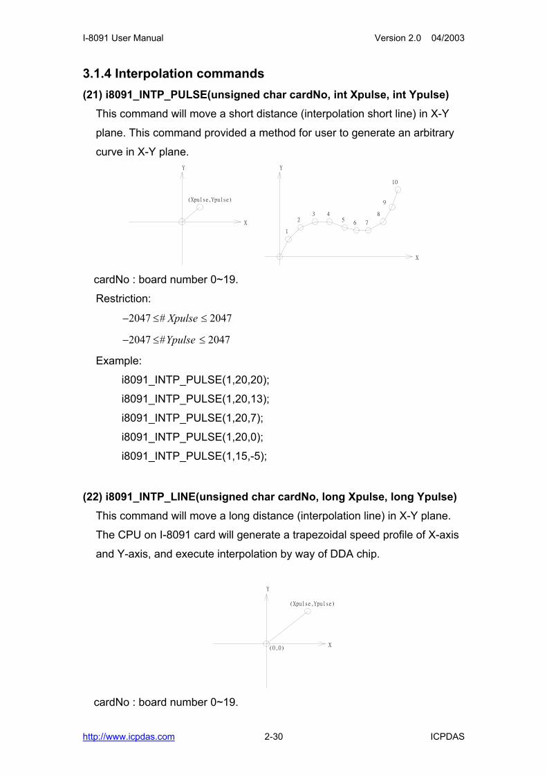
3.1.4 Interpolation commands (21) i8091_INTP_PULSE(unsigned char cardNo, int Xpulse, int Ypulse)
This command will move a short distance (interpolation short line) in X-Y
plane. This command provided a method for user to generate an arbitrary
curve in X-Y plane.
X
Y
(Xpulse,Ypulse)
X
Y
1
23 4
56 7
8
9
10
cardNo : board number 0~19.
Restriction:
− ≤ ≤2047 2047# Xpulse
− ≤ ≤2047 2047#Ypulse
Example:
i8091_INTP_PULSE(1,20,20);
i8091_INTP_PULSE(1,20,13);
i8091_INTP_PULSE(1,20,7);
i8091_INTP_PULSE(1,20,0);
i8091_INTP_PULSE(1,15,-5);
(22) i8091_INTP_LINE(unsigned char cardNo, long Xpulse, long Ypulse) This command will move a long distance (interpolation line) in X-Y plane.
The CPU on I-8091 card will generate a trapezoidal speed profile of X-axis
and Y-axis, and execute interpolation by way of DDA chip.
X
Y
(0,0)
(Xpulse,Ypulse)
cardNo : board number 0~19.
http://www.icpdas.com 2-30 ICPDAS

I-8091 User Manual Version 2.0 04/2003
Restriction:
− ≤ ≤524287 524287# Xpulse
− ≤ ≤524287 524287#Ypulse
Example:
i8091_INTP_LINE(1,2000,-3000);
i8091_INTP_LINE(1,-500,200);
(23) i8091_INTP_LINE02(unsigned char cardNo, long x, long y , unsigned int speed , unsigned char acc_mode)
This command will move a long interpolation line in X-Y plane. Host will
automaticly generate a trapezoidal speed profile of X-axis and Y-axis by
state-machine-type calculation method. The i8091_INTP_LINE02() only set
parameters into the driver. User can directly call the do { } while (i8091_INTP_STOP( ) !=READY) to execute the computing entity.
cardNo : board number 0~19.
speed : 0~2040
acc_mode: 0: enable acceleration and deceleration profile
1: disable acceleration and deceleration profile
X
Y
(0,0)
(X,Y)
Example:
i8091_INTP_LINE02(CARD1,1000,1000,100,0);
do { } while( i8091_INTP_STOP()!=READY) ; //call state machine
(24) i8091_INTP_CIRCLE02(unsigned char cardNo, long x, long y, unsigned char dir, unsigned int speed, unsigned char acc_mode)
This command will generate an interpolation circle in X-Y plane. Host will
http://www.icpdas.com 2-31 ICPDAS

I-8091 User Manual Version 2.0 04/2003
automaticly generate a trapezoidal speed profile of X-axis and Y-axis by
state-machine-type calculation method. The i8091_INTP_CIRCLE02() only
set parameters into the driver. User can directly call the do { } while (i8091_INTP_STOP( ) !=READY) to execute the computing entity.
cardNo : board number 0~19.
x, y : center point of circle relate to present position.
dir : moving direction.
0 : CW
1 : CCW
speed : 0~2040
acc_mode: 0: enable acceleration and deceleration profile
1: disable acceleration and deceleration profile
X
Y
(X,Y)
CCW
CW
where radius = sqrt(X^2 + Y^2)
Example:
i8091_INTP_CIRCLE02(CARD1,2000,2000,100,0);
do { } while( i8091_INTP_STOP()!=READY) ; //call state machine
(25) i8091_INTP_ARC02(unsigned char cardNo, long x, long y, long R, unsigned char dir, unsigned int speed, unsigned char acc_mode)
This command will generate an interpolation arc in X-Y plane. Host will
automaticly generate a trapezoidal speed profile of X-axis and Y-axis by
state-machine-type calculation method. The i8091_INTP_ARC02() only set
parameters into the driver. User can directly call the do { } while (i8091_INTP_STOP( ) !=READY) to execute the computing entity.
cardNo : board number 0~19.
http://www.icpdas.com 2-32 ICPDAS

I-8091 User Manual Version 2.0 04/2003
x, y : end point of arc relate to present position.
R : radius of arc.
if R>0 , the arc < 180degree
if R<0 , the arc > 180 degree
dir : moving direction.
0 : CW
1 : CCW
R dir path of curve
R>0 CW 'B'
R>0 CCW 'C'
R<0 CW 'A'
R<0 CCW 'D'
speed : 0~2040
acc_mode: 0: enable acceleration and deceleration profile
1: disable acceleration and deceleration profile
X
Y (X,Y)
CCW
CW
CW
CCW
'A'
'B'
'C'
'D'
Restriction:
− + ≤ ≤ −2 1 2 132 32# x
− + ≤ ≤ −2 1 2 132 32# y
− + ≤ ≤ −
≥+
2 1 2
2
32 32
2 2
# R
Rx y
1
http://www.icpdas.com 2-33 ICPDAS

I-8091 User Manual Version 2.0 04/2003
Example:
i8091_INTP_ ARC02(1,2000,-2000,2000,CW,100,0);
do { } while( i8091_INTP_STOP()!=READY) ; //call state machine
(26) unsigned char i8091_INTP_STOP() The above 3 state-machine-type interpolation commands
i8091_INTP_LINE02(), i8091_INTP_CIRCLE02() and
i8091_INTP_ARC02() must use i8091_INTP_STOP() simultaneously. The
state-machine-type interpolation commands are only set parameters into
the driver. The computing entity is in i8091_INTP_STOP(). This command will compute the interpolation profile. It will return
READY(0) for interpolation command completed. And retrun BUSY(1) for
not yet complete.
http://www.icpdas.com 2-34 ICPDAS
I-8091 User Manual Version 2.0 04/2003
3.1.5 Others (27) unsigned char i8091_LIMIT_X(unsigned char cardNo)
to request the condition of X-axis limit switches
cardNo : board number 0~19.
MSB 7 6 5 4 3 2 1 0 LSB /EMG /FFFF /FFEF /LS14 xx xx /LS11 /ORG1
/ORG1 : original point switch of X-axis, low active.
/LS11, /LS14 : limit switches of X-axis, low active, which must be
configured as Fig.(5).
/EMG : emergency switch, low active.
/FFEF : active low, FIFO is empty
/FFFF : active low, FIFO is full
Example:
unsigned char limit1;
limit1 = i8091_LIMIT_X(1);
(28) unsigned char i8091_LIMIT_Y(unsigned char cardNo) to request the condition of Y-axis limit switches
cardNo : board number 0~19.
MSB 7 6 5 4 3 2 1 0 LSB ystop xstop xx /LS24 xx xx /LS21 /ORG2
/ORG2 : original point switch of Y-axis, low active.
/LS21, /LS24 : limit switches of Y-axis, low active, which must be
configured as Fig.(6).
xstop: 1:indicate X-axis is stop
ystop: 1:indicate Y-axis is stop
Example:
unsigned char limit2;
limit2 = i8091_LIMIT_Y(1);
(29) i8091_WAIT_X(unsigned char cardNo) to wait X-axis going to STOP state.
cardNo : board number 0~19.
http://www.icpdas.com 2-35 ICPDAS

I-8091 User Manual Version 2.0 04/2003
(30) i8091_WAIT_Y(unsigned char cardNo) to wait Y-axis going to STOP state.
cardNo : board number 0~19.
(31) unsigned char i8091_IS_X_STOP(unsigned char cardNo) To check whether X axis is STOP or not. Return value 0 (NO) : not yet stop 1 (YES) : stop
(32) unsigned char i8091_IS_Y_STOP(unsigned char cardNo)
To check whether Y axis is STOP or not. Return value 0 (NO) : not yet stop 1 (YES) : stop
http://www.icpdas.com 2-36 ICPDAS

I-8091 User Manual Version 2.0 04/2003
3.2 Start up and end of program
Start up program
When you are going to use I-8091 card, there are some commands must
be implement in previous.
i8091_REGISTRATION(CARD1,0x80) set CARD1 address, (where CARD1=1)
i8091_RESET_SYSTEM(CARD1); reset system
i8091_SET_VAR(CARD1, DDA, AD, LSP, HSP); set DDA cycle, accelerating/decelerating speed, low speed and high
speed value
i8091_SET_DEFDIR(CARD1, xdir, ydir); define direction.
i8091_SET_MODE(CARD1, xmode, ymode); define output mode.
i8091_SET_SERVO_ON(CARD1, xson, yson); set servo ON/OFF.
define output mode.
i8091_SET_NC(CARD1, nc); To config limit switch as N.C. or N.O.
end of program
i8091_RESET_SYSTEM(CARD1); To reset system
Example //-----------------------------------------------------------------------------
-
#define CARD1 1
typedef struct {
int address;
unsigned char DDA,AD;
unsigned int LSP,HSP;
unsigned char xmode,ymode;
unsigned char xdir,ydir;
unsigned char xson,yson;
unsigned char NCmode;
http://www.icpdas.com 2-37 ICPDAS

I-8091 User Manual Version 2.0 04/2003
} i8091CardType;
i8091CardType card1;
//-------------------------------------------------------------------------
void main ()
{
card1.address=PortAddress[i8091Slot];
card1.DDA = 10;
card1.AD = 5;
card1.LSP = 5;
card1.HSP = 100;
card1.xmode = CW_CCW;
card1.ymode = CW_CCW;
card1.xdir = NORMAL_DIR;
card1.ydir = NORMAL_DIR;
card1.xson = ON;
card1.yson = ON;
card1.NCmode= OFF;
i8091_REGISTRATION(CARD1, card1.address);
i8091_RESET_SYSTEM(CARD1);
i8091_SET_VAR(CARD1, card1.DDA, card1.AD, card1.LSP, card1.HSP);
i8091_SET_DEFDIR(CARD1, card1.xdir, card1.ydir);
i8091_SET_MODE(CARD1, card1.xmode, card1.ymode);
i8091_SET_SERVO_ON(CARD1, card1.xson, card1.yson);
i8091_SET_NC(CARD1, card1.NCmode);
Delay(100);
.
.
//--- end of program ----------------------------
i8091_RESET_SYSTEM(CARD1);
}
http://www.icpdas.com 2-38 ICPDAS

I-8091 User Manual Version 2.0 04/2003
4. Example
4.1 Detect I-8091 card //---------------------------------------------------
// detect i8090,i8091,i8092 card
//---------------------------------------------------
#include "8000.h"
#include "s8090.h"
#define i8090 0x0d
#define i8091 0x0e
#define i8092 0x0f
#define NOCARD 0x00
#define MAX_SLOT_NO 8
unsigned int PortAddress[8]={0x080, 0x0a0, 0x0c0, 0x0e0, 0x140, 0x160,
0x180, 0x1a0};
//---------------------------------------------------
void main ()
{
unsigned char slot,temp;
for (slot=0; slot<MAX_SLOT_NO; slot++)
{
temp=inportb(PortAddress[slot]);
switch (temp)
{
case i8090: //i8090 3-axis encoder card
Print("Slot %d = i8090\r\n",SlotNum);
return i8090;
case i8091: //i8091 2-axis stepping card
Print("Slot %d = i8091\r\n",SlotNum);
return i8091;
case i8092: //i8092
Print("Slot %d = i8092\r\n",SlotNum);
http://www.icpdas.com 2-39 ICPDAS

I-8091 User Manual Version 2.0 04/2003
return i8092;
default:
Print("Slot %d = No Card\r\n",SlotNum);
return NOCARD;
};
Delay(500);
};
}
4.2 Example: DEMO.cpp //---------------------------------------------------------------------------
// demo.cpp for I-8091 card
//
// This program can test all of following command
// ----------------------I-8091 testing kit-----------------------------------
// (0)Exit (A)i8091_IS_X_STOP (K)i8091_CSP_MOVE
// (1)i8091_RESET_SYSTEM (B)i8091_IS_Y_STOP (L)i8091_SLOW_DOWN
// (2)i8091_SET_VAR (C)i8091_LIMIT_X (M)i8091_SLOW_STOP
// (3)i8091_SET_DEFDIR (D)i8091_LIMIT_Y (N)i8091_INTP_PULSE
// (4)i8091_SET_MODE (E)i8091_LSP_ORG (O)i8091_INTP_LINE
// (5)i8091_SET_SERVO_ON (F)i8091_HSP_ORG (P)i8091_INTP_LINE02
// (6)i8091_SET_NC (G)i8091_LSP_PULSE_MOVE (Q)i8091_CIRCLE02
// (7)i8091_STOP_X (H)i8091_HSP_PULSE_MOVE (R)i8091_ARC02
// (8)i8091_STOP_Y (I)i8091_LSP_MOVE (S)User Define Testing
// (9)i8091_STOP_ALL (J)i8091_HSP_MOVE
//
// The output pulse amount can be monitored from i8090 card. When directly
// connect the CW/PULSE, CCW/DIR of i8091 to i8090. The encoder value
// can be shown on the LED display. Its format as following.
// ex: 0.2 1 2 8 : X-axis encoder value
// 5 3.4 0 2 : Y-axis encoder value
// 1 0 0.1 0 : Z-axis encoder value
// the dot(.) stands for which axis.
//--------------------------------------------------------------------
4.3 Example:DEMO1.cpp //--------------------------------------------------------------------
// demo1.cpp for I-8091 card
//
// This a simple program to test I-8091 command
// i8091_INTP_LINE()
// i8091_INTP_LINE02()
//--------------------------------------------------------------------
http://www.icpdas.com 2-40 ICPDAS