i-71 nb at sr 82 eb interchange operations study … · p a g e | 8 i-71 nb at sr 82 eb interchange...
TRANSCRIPT

Prepared for: The Ohio Department of Transportation District 12 5500 Transportation Boulevard Garfield Heights, OH 44125
Prepared by:
18013 Cleveland Parkway Drive Suite 200
Cleveland, OH 44135
I-71 NB at SR 82 EB Interchange Operations Study December 2015

Contents
I. Executive Summary .......................................................................................................................... 1
II. Background ...................................................................................................................................... 4
III. Purpose & Need ............................................................................................................................... 4
IV. Study Area ........................................................................................................................................ 4
V. Existing Conditions ........................................................................................................................... 7
VI. Analysis Years ................................................................................................................................... 9
VII. Alternatives Considered ................................................................................................................. 10
VIII. Traffic Volumes .............................................................................................................................. 12
IX. Traffic Analyses .............................................................................................................................. 12
X. Cost Estimate ................................................................................................................................. 16
VIII. Environmental Overview ............................................................................................................... 17
IX. Conclusion and Recommendations ............................................................................................... 17
Figure 1 - 2035 No Build LOS Summary ........................................................................................................ 2
Figure 2 - 2035 Build LOS Summary .............................................................................................................. 3
Figure 3 - Study Area ..................................................................................................................................... 5
Figure 4 - I-71/SR 82 Interchange with Signal Spacing ................................................................................. 6
Figure 5 – 2014 ODOT HSP Priority Rankings ................................................................................................ 8
Figure 6 - Land Use Map ............................................................................................................................... 9
Figure 7 - Build Condition............................................................................................................................ 11
Figure 8 – Intersection LOS Summary ......................................................................................................... 12
Figure 9 – SR 82 Coordinated System LOS Summary .................................................................................. 13
Figure 10 – Freeway Segment LOS Summary ............................................................................................. 14
Figure 11 – Merge/Diverge LOS Summary .................................................................................................. 15
Table 1 - Functional Classification ................................................................................................................. 7
Table 2 - Build Condition Cost Estimate ...................................................................................................... 16
Appendix A – 2013 Census Data Appendix B – Certified Traffic Appendix C – Capacity Analysis Appendix D – Cost Estimate

I. Executive Summary The Ohio Department of Transportation (ODOT) commissioned Hatch Mott MacDonald (HMM) to conduct an Interchange Operations Study at the Interstate 71 (I-71) / SR 82 interchange (CUY-71-2.57) located in the City of Strongsville, Cuyahoga County, Ohio. The City of Strongsville is looking for a long-term solution to reduce congestion and decrease crashes in the study area. Several short to medium term countermeasures have been implemented or studied with little improvement to congestion or crashes. HMM evaluated the Build Condition for traffic operations, safety and to determine any impacts to the existing freeway network. The Build Condition includes widening the SR 82 EB to I-71 NB entrance ramp allowing an additional SR 82 EB lane to access I-71 NB. The proposed ramp widening will taper back to a single travel lane prior to merging with I-71. This improvement is proposed to specifically address the severe lane imbalance, congestion and rear end crashes on SR 82 EB. The proposed improvement may also have a positive impact on the overall congestion and crash problems in the study area by improving the efficiency of the adjacent I-71 SB and Howe Road signals. Based on the analyses presented in this report, the Build condition does not degrade or otherwise negatively affect freeway operations on I-71. The Build condition is expected to improve the efficiency of the SR 82 coordinated signal system and thus reduce travel times, fuel consumption, emissions, and crashes. Improving the efficiency of the SR 82 signal system may also help mitigate queues that currently extend onto the I-71 SB mainline during periods of high traffic volumes. Therefore, the Build condition is recommended.

P a g e | 2
I-71 NB at SR 82 EB Interchange Operations Study December 2015
Figure 1 - 2035 No Build LOS Summary

P a g e | 3
I-71 NB at SR 82 EB Interchange Operations Study December 2015
Figure 2 - 2035 Build LOS Summary

P a g e | 4
I-71 NB at SR 82 EB Interchange Operations Study December 2015
II. Background The Ohio Department of Transportation (ODOT) commissioned Hatch Mott MacDonald (HMM) to conduct an Interchange Operations Study (IOS) of the Interstate 71 (I-71) / SR 82 interchange (CUY-71-2.57) located in the City of Strongsville, Cuyahoga County, Ohio. This IOS expands upon the preparation of the “I-71 at SR 82 Interchange Operation Analysis” completed by HMM on April 15, 2013. The study follows IOS procedures and guidance as given by the ODOT Office of Roadway Engineering. A formal safety study was also completed by ODOT District 12 in July of 2012. The study focused on approximately one mile of SR 82 centered at the SR 82/Howe intersection, including the I-71 / SR 82 interchange. The safety study focused on short and medium term countermeasures. Several of the short-term countermeasures from the study have already been implemented by the City of Strongsville. Recently implemented short-term improvements include:
- All noted non-functioning loop detectors were repaired. - All noted non-functioning pedestrian crossings were repaired. - Signal displays on Howe Road northbound revised to be OMUTCD compliant. - Intersection dotted lines were re-positioned from the Howe Road northbound right turn lane to
SR 82 and Southpark Center Road to SR 82. - Additional left turn storage was provided along with a second left turn lane on SR 82 eastbound
at Howe Road. - A signal progression study was performed and timings were improved to reduce queuing onto
I-71 southbound to the extent possible. As part of this study, weekend and holiday timing plans were also evaluated and optimized (PID 94550).
III. Purpose & Need Congestion on SR 82 at the I-71 interchange and adjacent areas caused by high travel demand is pushing the limits of the existing transportation network. The congestion has also brought safety concerns as this area is high on ODOT’s Highway Safety Program (HSP) Priority List (see Figure 5). The purpose of this study is to examine a long term countermeasure to improve safety by reducing congestion throughout the SR 82 corridor and the I-71 / SR 82 interchange study area.
IV. Study Area The study area consists of I-71 from the SR 303 interchange to the I-80 (Ohio Turnpike) interchange and SR 82 from Howe Road through the I-71 interchange. See Figure 3 & Figure 4.

P a g e | 5
I-71 NB at SR 82 EB Interchange Operations Study December 2015
Figure 3 - Study Area

P a g e | 6
I-71 NB at SR 82 EB Interchange Operations Study December 2015
Figure 4 - I-71/SR 82 Interchange with Signal Spacing

P a g e | 7
I-71 NB at SR 82 EB Interchange Operations Study December 2015
V. Existing Conditions
a. Road Geometry & Access Locations The existing I-71 / SR 82 interchange is a full-access, partial cloverleaf interchange. SR 82 is the major east-west roadway through the area and is heavily commerical from US 42 to I-71 with large retail centers on both the north and south sides of the roadway including Southpark Mall. Areas further to the south of SR 82 are largely residential. US 42 is a major north-south arterial located about one mile west of I-71 which is also heavily commercial.
Table 1 - Functional Classification within Study Area
Functional Class Legal Speed Limit
I-71 Urban Interstate 60
SR 82 Urban Principal Arterial 35
Current ADT on SR 82 in the project area is approximately 45,000 vehicles per day. Signalized intersections along with distances between each are shown on Figure 4. SR 82 traffic signals are part of a coordinated, closed loop system.
b. Physical Conditions – Terrain The terrain is relatively flat is this area. I-71 passes under SR 82.
c. Crash Data Based on the Formal Safety Study completed in July of 2012, an analysis of traffic crashes from 2008 – 2010 reveal that 289 crashes occurred on the SR 82 corridor from MP 2.7 to 3.7 with about 25% of all crashes resulting in an injury. Rear end crashes account for over 70% of all crashes. Crash frequency is highest during the weekday PM peak hours (4:00 – 7:00 PM), on Saturdays, and during the months of November and December. The high crash frequency periods directly correlate with the highest traffic volume periods. Figure 5 on the following page shows the number of ODOT Highway Safety Program safety priority locations that are within the project area.

P a g e | 8
I-71 NB at SR 82 EB Interchange Operations Study December 2015
Green = Urban Intersection Safety Priority Location and Rank Blue = Urban Non-Freeway Safety Priority Location and Rank
Red = Urban Freeway Safety Priority Location and Rank
SR 82 / Howe Rd - Urban Intersection, HSP Priority Ranking #12 (2012), #99 (2013)
** SR 82 3.26-3.36 - Urban Non-Freeway Segment, HSP Priority Ranking #27 (2012), #32 (2013)
Figure 5 – 2014 ODOT HSP Priority Rankings
#114* #376
#178
#62**
#383
#361
#123 #366

P a g e | 9
I-71 NB at SR 82 EB Interchange Operations Study December 2015
d. Demographics Per 2013 Census data, The City of Strongsville has a total population of approximately 45,000 people while Cuyahoga County has approximately 1.26 million people. Refer to Appendix A for more detailed information.
e. Land Use The land use along SR 82 and US 42 is largely commercial. The land use adjacent to these commercial areas is mostly single family residential. See Figure 6 for land use data retrieved from the Cuyahoga County GIS.
VI. Analysis Years The current year traffic used for analysis is considered 2015 while the design year is established as 2035. Traffic analysis within this IOS uses 2035 design year volumes provided by ODOT’s Office of Statewide Planning & Research. The No Build condition is defined as the existing geometry and lane use with revised traffic signal timing and coordination. The Build condition is defined as the proposed improvement as presented in Figure 7. This includes widening the SR 82 EB to I-71 NB loop ramp to two lanes allowing an additional SR 82 EB lane to access I-71 NB by converting the outside through lane to a decision lane.
Figure 6 - Land Use Map

P a g e | 10
I-71 NB at SR 82 EB Interchange Operations Study December 2015
VII. Alternatives Considered The following alternatives have been considered as part of this or prior studies:
1. No Build – The No Build condition is defined as the existing geometry and lane use.
2. Short-Term – Several short term improvements have been implemented, are in the process of being implemented, or have been previously studied. They are as follows:
a. Pavement marking changes – based on the formal safety study from July of 2012, several pavement marking changes have occurred on SR 82 between I-71 and the Southpark Mall entrances to improve turn lane use and efficiency (ex: the SR 82 EB left turn storage capacity at Howe Road was increased by providing a dual turning lane and extending the existing turning lane based on updated traffic count information).
b. Signal timing / coordination optimization – ODOT completed a signal optimization study and implemented optimized timings for the SR 82 closed loop system which runs from US 42 through the I-71 interchange intersections. In addition, the City of Strongsville is sponsoring a city-wide traffic signal coordination and upgrade project which will include central monitoring and adaptive signal control.
3. Ramp Metering – Ramp metering was dismissed as a viable option at this interchange because the congestion and crash problem is more prevalent on SR 82 as well as the I-71 SB to SR 82 WB exit ramp and ramp storage would likely degrade operations of SR 82. In addition, metering is typically applied on a corridor wide basis and at this time there is no ramp metering in this area. Ramp metering was tried at this interchange in the past for the SR 82 WB to I-71 NB entrance ramp. The ramp metering signal was removed not long after installation.
4. SR 82 / Howe Road Intersection Reconstruction – Parsons Brinckerhoff, through ODOT District 12, evaluated alternative intersection designs at the SR 82 / Howe Road intersection such as a roundabout, continuous flow intersection (CFI), and median U-turns in a safety study dated November 2014. The close proximity of the I-71 interchange, physical site constraints, major disruption of traffic, and high construction / ROW costs prohibited these options as being viable at this time.
5. New I-71 Interchange – Several studies have been conducted in the past to explore the feasibility of constructing a new interchange on I-71 between SR 303 and SR 82. Based on a teleconference on March 2, 2015 between HMM, District 12, and the Office of Roadway Engineering, ODOT has dismissed this alternative due to high costs, ROW needs, and a lack of support by local municipalities and ODOT.
6. Additional I-71 SB Exit Ramp – As part of the SR 82 interchange, an additional I-71 SB exit ramp tying directly into Howe Road south of SR 82 is being explored in conjunction with this study.
7. Build – The Build condition studied in this report will represent the following proposed conditions: a. Widen the SR 82 EB to I-71 NB entrance loop ramp to accommodate two receiving lanes. b. Modify SR 82 EB lane configuration by making the outside through lane a decision lane. c. Optimize signal timings and coordination parameters.

P a g e | 11
I-71 NB at SR 82 EB Interchange Operations Study December 2015
One of the major identified issues associated with congestion and crashes in the project area is lane imbalance. This is particularly prevalent in the curb lane on SR 82 eastbound and for the northbound right turn movement of Howe Road at SR 82. Both conditions are directly related to the existing access to I-71 NB. Currently, the same SR 82 EB lane is the only lane that accesses both I-71 NB and SB. With only one lane for the heavy SR 82 EB to I-71 NB movement (over 1600 AM peak and 1100 PM peak vehicles), extended queues form in the curb lanes on SR 82 EB and Howe Road NB while the other lanes are under-utilized. During peak periods, the SR 82 EB curb lane queue lengths extend approximately three quarters of a mile to the western mall entrance and Howe Road NB curb lane queue lengths extend over 1000 feet in order to get into the lane that eventually accesses I-71 NB. The Build condition specifically addresses this lane imbalance with the intent to distribute SR 82 EB traffic across two lanes to access I-71 NB. Build Condition Design Standards The proposed Build condition improvements meet ODOT design standards pertaining to roadway geometrics and interchange elements. Build Condition Limits of L/A ROW All proposed work for the Build condition is within existing ROW limits.
Figure 7 - Build Condition

P a g e | 12
I-71 NB at SR 82 EB Interchange Operations Study December 2015
VIII. Traffic Volumes ODOT’s Office of Statewide Planning & Research provided certified traffic forecasts on June 19, 2013. Certified traffic was provided for AM/PM peaks, ADT’s, and truck factors for 2015 (current year) and 2035 (design year) No Build and Build conditions. See Appendix B for certified traffic.
IX. Traffic Analyses Level of Service Per the Highway Capacity Manual, a Level of Service (LOS) C is desired for the interstate/freeway system and interchange components of the Build condition. The Northeast Ohio Areawide Coordinating Agency (NOACA) accepts LOS D or better within their Metropolitan Planning Organization (MPO) boundaries. Full capacity reports are available in Appendix C. Intersections Traffic analysis was completed for the I-71 intersections with SR 82 during the AM and PM peak hours under the No Build and Build conditions. The intersections were analyzed to determine LOS given existing conditions (No Build) and to appropriately size the intersection given proposed conditions (Build). Analyses followed ODOT balancing procedures where the worst east-west approach was balanced within three seconds of the worst north-south approach where possible. Per ODOT procedures, HMM utilized Highway Capacity Software (HCS) 2010 to analyze the I-71 NB intersection while Synchro 8 was used for the I-71 SB intersection due to limitations of HCS given the geometrics and signal phasing of the intersection. The change in delay at the I-71 SB intersection was due to a change in lane utilization in the Build Condition. In addition, the signal was analyzed in Synchro 8 to measure coordination parameters and the interaction between other signals within the SR 82 closed loop system. Synchro results are shown for the SR 82/I-71 NB intersection as well as the two upstream intersections on SR 82. Note that the volumes are the same in the No Build and Build conditions.
LOS Delay LOS Delay LOS Delay LOS Delay
13 SR 82 & I-71 NB C 20.0 C 20.0 13 SR 82 & I-71 NB C 22.0 C 22.0
EB Approach B 13.0 B 13.0 EB Approach C 28.0 C 28.0
WB Approach C 21.8 C 21.8 WB Approach B 12.7 B 12.7
NB Approach C 23.7 C 23.7 NB Approach C 31.3 C 31.3
14 SR 82 & I-71 SB1 F 85.2 C 33.1 14 SR 82 & I-71 SB1 F 104.2 D 49.0
EB Approach F 111.6 C 33.3 EB Approach F 145.7 D 45.9
WB Approach C 29.8 C 32.2 WB Approach D 54.9 D 52.1
NB Approach E 60.1 C 32.0 NB Approach F 145.1 D 46.2
SB Approach F 110.0 C 34.6 SB Approach E 70.3 D 51.81 SR 82 & I-71 SB analysis completed in Synchro. Unable to analyze in HCS due to limitations of software
LocationID
AM No Build vs Build PM No Build vs Build
ID Location2035 No Build 2035 Build2035 No Build 2035 Build
Figure 8 – Intersection LOS Summary

P a g e | 13
I-71 NB at SR 82 EB Interchange Operations Study December 2015
Delay was reduced more in the Build condition for the intersections upstream of the SR 82/I-71 NB
intersection. This is a direct effect of the expected lane balancing on SR 82 EB given the Build condition.
LOS Delay LOS Delay LOS Delay LOS Delay
13 SR 82 & I-71 NB B 17.9 B 16.4 13 SR 82 & I-71 NB B 16.5 C 20.5
EB Approach A 4.7 A 7.6 EB Approach A 7.2 B 15.5
WB Approach B 11.1 B 13.5 WB Approach A 9.6 B 10.4
NB Approach E 61.8 E 66.9 NB Approach E 63.7 E 74.4
14 SR 82 & I-71 SB E 57.7 C 24.9 14 SR 82 & I-71 SB F 105.5 D 50.5
EB Approach F 80.2 A 8.0 EB Approach F 137.4 A 8.8
WB Approach C 28.3 C 32.3 WB Approach D 54.3 D 54.1
NB Approach E 58.8 E 58.8 NB Approach F 139.7 F 139.7
SB Approach D 43.9 D 42.8 SB Approach F 91.0 E 65.6
SR 82 & Howe F 125.4 D 38.2 SR 82 & Howe F 130.4 F 99.3
EB Approach F 221.4 D 35.2 EB Approach F 204.8 F 100.6
WB Approach C 34.4 C 28.6 WB Approach F 117.5 F 117.2
NB Approach F 174.2 E 62.1 NB Approach D 53.5 D 53.5
SB Approach D 51.9 D 51.9 SB Approach E 69.1 E 69.2
2035 Build
AM No Build vs Build PM No Build vs Build
ID Location2035 No Build 2035 Build
ID Location2035 No Build
Figure 9 – SR 82 Coordinated System LOS Summary

P a g e | 14
I-71 NB at SR 82 EB Interchange Operations Study December 2015
Freeway Section Analysis
HMM analyzed freeway segments on I-71 NB following ODOT methodology using HCS 2010. Segments were analyzed between interchanges and within interchanges between merge and diverge points. A summary is below. Note that no changes to the I-71 Mainline are proposed for the Build condition. Certified traffic volumes for each I-71 analysis point remained the same between the No Build and Build conditions.
In the AM, the NB section of I-71 from SR 82 to I-80 is LOS E for the No Build & Build conditions.
In the AM, the NB section of I-71 at I-80 is LOS E for No Build & Build conditions.
The proposed Build condition does not degrade freeway segment operations.
LOS Density LOS Density2 @ SR 303 3 C 20.1 C 20.1
4 SR 303 to SR 82 3 C 21.8 C 21.8
6 @ SR 82 EB 3 C 19.5 C 19.5
8 @ SR 82 WB 3 D 30.5 D 30.5
10 SR 82 to I-80 3 E 41.8 E 41.8
12 @ I-80 3 E 36.9 E 36.9
IDI-71 Northbound
SegmentLanes
AM No Build vs Build2035 No Build 2035 Build
LOS Density LOS Density2 @ SR 303 3 B 11.2 B 11.2
4 SR 303 to SR 82 3 B 13.1 B 13.1
6 @ SR 82 EB 3 A 10.2 A 10.2
8 @ SR 82 WB 3 B 16.8 B 16.8
10 SR 82 to I-80 3 C 19.0 C 19.0
12 @ I-80 3 B 16.9 B 16.9
2035 BuildID
I-71 Northbound
SegmentLanes
PM No Build vs Build2035 No Build
Figure 10 – Freeway Segment LOS Summary

P a g e | 15
I-71 NB at SR 82 EB Interchange Operations Study December 2015
Merge / Diverge Analysis HMM analyzed the LOS at merge and diverge points along I-71 NB within the project area following ODOT methodology using HCS 2010. Note that although the SR 82 EB to I-71 NB entrance ramp is widened in the Build condition, the forecasted traffic volume at the merge point after the ramp has been reduced back to a single lane remains the same. All other merge and diverge analysis points also remain the same between the No Build and Build conditions.
In the AM, the SR 82 WB entrance ramp to I-71 NB operates with a merge LOS E for the No Build and Build conditions.
The proposed Build condition does not degrade freeway operations for merge and diverge points.
LOS Density LOS Density
@ SR 303
1 Merge 1 C 22.0 C 22.0
3 Merge 2 C 21.5 C 21.5
@ SR 82
5 Diverge C 24.7 C 24.7
7 Merge 1 D 32.8 D 32.8
9 Merge 2 E 36.5 E 36.5
@ I-80
11 Diverge D 34.6 D 34.6
AM No Build vs Build
ID I-71 NB2035 No Build 2035 Build
LOS Density LOS Density
@ SR 303
1 Merge 1 B 12.4 B 12.4
3 Merge 2 B 13.7 B 13.7
@ SR 82
5 Diverge B 16.4 B 16.4
7 Merge 1 C 20.3 C 20.3
9 Merge 2 C 20.2 C 20.2
@ I-80
11 Diverge C 21.3 C 21.3
PM No Build vs Build
ID I-71 NB2035 No Build 2035 Build
Figure 11 – Merge/Diverge LOS Summary

P a g e | 16
I-71 NB at SR 82 EB Interchange Operations Study December 2015
Constrained Analysis Constrained analysis is not required as the Build condition does not cause freeway degradation as defined in the ODOT IMS Traffic Academy Manual.
X. Cost Estimate The cost estimate for the Build condition, completed by EMH&T as part of PID 99435, is approximately $857,000. A breakdown by group is provided below. A detailed cost estimate is provided in Appendix D.
Table 2 - Build Condition Cost Estimate
Group Cost
Roadway $ 205,000
Erosion Control $ 45,500
Drainage $ 35,500
Pavement $ 359,500
Lighting $ 24,500
Traffic Control $ 36,000
Maintenance of Traffic $ 86,000
Incidentals $ 41,500
Subtotal $ 833,500
Inflation (2016) 2.8 %
Total $ 857,000 This improvement is funded by a 90% federal share through the ODOT Highway Safety Improvement Program and a 10% local match by the City of Strongsville.

P a g e | 17
I-71 NB at SR 82 EB Interchange Operations Study December 2015
VIII. Environmental Overview Environmental Documentation was completed by ODOT District 12 with an Environmental Document Approval date of 8/14/2015. All proposed work will be in the public right of way. The only utility impacted by the Build condition is an electrical service cable owned by ODOT.
IX. Conclusion and Recommendations The I-71 / SR 82 interchange is heavily congested due to traffic demand from commercial areas adjacent to the interchange as well as the large residential population surrounding the commercial areas. Travel delays are high due to the congestion and a number of closely spaced signalized intersections. In addition, crash frequency is high within the study area as many locations fall under ODOT’s Highway Safety Program Priority List and have for several consecutive years. The Build Condition reduces queues on SR 82 EB by distributing traffic desiring to access I-71 NB over two lanes as opposed to one lane. By improving the lane utilization to a more balanced condition, the Build condition will allow the SR 82 coordinated signal system to operate more efficiently. Improving the existing lane imbalance on SR 82 EB is also expected to help reduce crashes. Specifically, rear end crashes are expected to decrease as a result of the reduced queue lengths in the SR 82 EB curb lane. The Build Condition does not degrade freeway operations. All intersections, freeway segments, merge and diverge locations operate with equal or improved LOS between the No Build and Build conditions. The Build Condition is expected to improve traffic operations along the SR 82 corridor and at the I-71 / SR 82 interchange. The presented Build condition provides an adequate traffic solution and is recommended to be carried forward.

Appendix A
2013 Census Data

OH - Cuyahoga County OH - Strongsville city
Total Population 1,280,122 Total Population 44,750
Total 621,763 Total 18,476
Occupied 545,056 Occupied 17,659
Owner-occupied 331,876 Owner-occupied 14,270
Population in owner-occupied Population in owner-occupied
( number of individuals ) ( number of individuals )
Renter-occupied 213,180 Renter-occupied 3,389
Population in renter-occupied Population in renter-occupied
( number of individuals ) ( number of individuals )
Households with individuals under 18 154,582 Households with individuals under 18 5,571
Vacant 76,707 Vacant 817
Vacant: for rent 32,522 Vacant: for rent 316
Vacant: for sale 9,679 Vacant: for sale 205
Male 607,362 Male 21,766
Female 672,760 Female 22,984
Under 18 290,262 Under 18 10,405
18 & over 989,860 18 & over 34,345
20 - 24 78,335 20 - 24 1,951
25 - 34 157,986 25 - 34 4,014
35 - 49 254,121 35 - 49 9,567
50 - 64 266,049 50 - 64 10,686
65 & over 198,541 65 & over 7,189
Hispanic or Latino 61,270 Hispanic or Latino 912
Non Hispanic or Latino 1,218,852 Non Hispanic or Latino 43,838
White 814,103 White 41,185
African American 380,198 African American 845
Asian 32,883 Asian 1,833
American Indian and Alaska Native 2,578 American Indian and Alaska Native 42
Native Hawaiian and Pacific Islander 285 Native Hawaiian and Pacific Islander 14
Other 23,339 Other 190
Identified by two or more 26,73 Identified by two or more 641
Population by Ethnicity
Population by Race
Population
Housing Status( in housing units unless noted )
37,978
6,468
Population by Sex/Age
Population by Ethnicity
Population by Race
Population
Housing Status( in housing units unless noted )
804,136
446,735
Population by Sex/Age

OH - Medina County OH - Brunswick city
Total Population 172,332 Total Population 34,255
Total 69,181 Total 13,600
Occupied 65,143 Occupied 12,967
Owner-occupied 52,536 Owner-occupied 10,190
Population in owner-occupied Population in owner-occupied
( number of individuals ) ( number of individuals )
Renter-occupied 12,607 Renter-occupied 2,777
Population in renter-occupied Population in renter-occupied
( number of individuals ) ( number of individuals )
Households with individuals under 18 22,966 Households with individuals under 18 4,695
Vacant 4,038 Vacant 633
Vacant: for rent 1,400 Vacant: for rent 322
Vacant: for sale 880 Vacant: for sale 135
Male 84,941 Male 16,830
Female 87,391 Female 17,425
Under 18 43,741 Under 18 8,644
18 & over 128,591 18 & over 25,611
20 - 24 7,801 20 - 24 1,738
25 - 34 17,926 25 - 34 3,983
35 - 49 39,633 35 - 49 8,040
50 - 64 36,696 50 - 64 6,949
65 & over 22,601 65 & over 4,079
Hispanic or Latino 2,747 Hispanic or Latino 790
Non Hispanic or Latino 169,585 Non Hispanic or Latino 33,465
White 165,642 White 32,706
African American 2,027 African American 422
Asian 1,660 Asian 420
American Indian and Alaska Native 247 American Indian and Alaska Native 51
Native Hawaiian and Pacific Islander 18 Native Hawaiian and Pacific Islander 6
Other 652 Other 204
Identified by two or more 2,086 Identified by two or more 44
Population by Ethnicity
Population by Race
Population
Housing Status( in housing units unless noted )
27,816
6,239
Population by Sex/Age
Population by Ethnicity
Population by Race
Population
Housing Status( in housing units unless noted )
143,720
27,414
Population by Sex/Age
Appendix B
Certified Traffic

INTER‐OFFICE COMMUNICATION
TO: Brian Blayney, P.E., Traffic Planning Engineer, District 12 FROM: Becky Salak, Transportation Planner, Office of Statewide Planning and Research SUBJECT: CUY‐71‐2.57, No PID Revised DATE: June 19, 2013 The attached plates have been revised, and replace the plates sent with the June 14, 2013 IOC. In reply to a request received May 24, 2013, plates are attached showing 2015/2035 ADT, A.M. DHV, and P.M. DHV turning movement forecasts for the no build and build scenarios. K & D factors can be calculated as needed. Truck factors are shown on a separate plate.
If you have any questions, please contact me at (614) 644‐8195. c: M. Byram, OSPR – G. Giaimo, OSPR – File


Appendix C
Capacity Analysis

Intersections
2035 AM

HCS 2010 Signalized Intersection Results Summary
General Information Intersection Information
Agency Hatch Mott MacDonald Duration, h 0.25
Analyst SJT Analysis Date Oct 20, 2015 Area Type Other
Jurisdiction Strongsville Time Period AM PHF 0.92
Intersection SR 82 @ I-71 NB Analysis Year 2035 Analysis Period 1> 7:00
File Name 13_SR82 & I-71 NB 2035 AM.xus
Project Description I-71 / SR 82 IMS
Demand Information EB WB NB SB
Approach Movement L T R L T R L T R L T R
Demand (v), veh/h 730 2040 290 0 120
Signal Information
GreenYellowRed
40.0 29.0 0.0 0.0 0.0 0.04.0 4.0 0.0 0.0 0.0 0.01.5 1.5 0.0 0.0 0.0 0.0
1 2 3 4
5 6 7
Cycle, s 80.0 Reference Phase 2
Offset, s 0 Reference Point End
Uncoordinated Yes Simult. Gap E/W On
Force Mode Fixed Simult. Gap N/S On
Timer Results EBL EBT WBL WBT NBL NBT SBL SBT
Assigned Phase 2 6 8
Case Number 8.0 8.0 10.0
Phase Duration, s 45.5 45.5 34.5
Change Period, (Y+Rc), s 5.5 5.5 5.5
Max Allow Headway (MAH), s 3.0 3.0 3.3
Queue Clearance Time (gs), s 13.7 33.6 14.6
Green Extension Time (ge), s 11.7 4.7 0.9
Phase Call Probability 1.00 1.00 1.00
Max Out Probability 0.21 0.80 0.00
Movement Group Results EB WB NB SB
Approach Movement L T R L T R L T R L T R
Assigned Movement 2 6 3 8 18
Adjusted Flow Rate (v), veh/h 793 2217 158 158
Adjusted Saturation Flow Rate (s), veh/h/ln 1756 1675 1740 1740
Queue Service Time (gs), s 11.7 31.6 5.1 5.1
Cycle Queue Clearance Time (gc), s 11.7 31.6 5.1 5.1
Green Ratio (g/C) 0.50 0.50 0.36 0.36
Capacity (c), veh/h 1756 2512 631 631
Volume-to-Capacity Ratio (X) 0.452 0.883 0.250 0.250
Available Capacity (ca), veh/h 1756 2512 631 631
Back of Queue (Q), veh/ln (50th percentile) 4.1 11.5 1.9 1.9
Queue Storage Ratio (RQ) (50th percentile) 0.00 0.00 0.20 0.20
Uniform Delay (d1), s/veh 12.9 17.9 17.9 17.9
Incremental Delay (d2), s/veh 0.1 3.9 0.1 0.1
Initial Queue Delay (d3), s/veh 0.0 0.0 0.0 0.0
Control Delay (d), s/veh 13.0 21.8 18.0 18.0
Level of Service (LOS) B C B B
Approach Delay, s/veh / LOS 13.0 B 21.8 C 23.7 C 0.0
Intersection Delay, s/veh / LOS 20.0 C
Multimodal Results EB WB NB SB
Pedestrian LOS Score / LOS
Bicycle LOS Score / LOS
Copyright © 2015 University of Florida, All Rights Reserved. HCS 2010™ Streets Version 6.50 Generated: 10/26/2015 3:30:29 PM
AM | 13

Timings2: I-71 SB Ramp & SR 82 Royalton Rd 12/11/2015
SR 82 & I-71 SB 7/11/2013 2035 AM No Build Synchro 8 ReportPage 1
Lane Group EBT EBR WBL WBT NBR2 SWR ø1 ø4Lane ConfigurationsVolume (vph) 2050 280 100 1130 370 960Turn Type NA Perm Prot NA pt+ov customProtected Phases 6 5 2 4 5 1 4 1 4Permitted Phases 6 6 2 1 4Detector Phase 6 6 5 2 4 5 1 4Switch PhaseMinimum Initial (s) 25.0 25.0 10.0 25.0 1.0 7.0Minimum Split (s) 32.0 32.0 17.0 32.0 20.0 20.0Total Split (s) 111.0 111.0 25.0 105.0 31.0 14.0Total Split (%) 74.0% 74.0% 16.7% 70.0% 21% 9%Yellow Time (s) 5.0 5.0 5.0 5.0 5.0 4.0All-Red Time (s) 2.0 2.0 2.0 2.0 2.0 2.0Lost Time Adjust (s) 0.0 0.0 0.0 0.0Total Lost Time (s) 7.0 7.0 7.0 7.0Lead/Lag Lead Lead Lag Lag LeadLead-Lag Optimize? Yes YesRecall Mode None None None None None MaxAct Effct Green (s) 104.0 104.0 18.0 98.0 33.0 38.0Actuated g/C Ratio 0.69 0.69 0.12 0.65 0.22 0.25v/c Ratio 1.22 0.27 1.03 0.40 0.68 1.09Control Delay 126.6 1.3 133.5 12.6 60.1 110.0Queue Delay 0.0 0.0 0.0 0.0 0.0 0.0Total Delay 126.6 1.3 133.5 12.6 60.1 110.0LOS F A F B E FApproach Delay 111.6 29.8Approach LOS F C
Intersection SummaryCycle Length: 150Actuated Cycle Length: 150Natural Cycle: 150Control Type: Actuated-UncoordinatedMaximum v/c Ratio: 1.22Intersection Signal Delay: 85.2 Intersection LOS: FIntersection Capacity Utilization Err% ICU Level of Service HAnalysis Period (min) 15
Splits and Phases: 2: I-71 SB Ramp & SR 82 Royalton Rd
AM No Build | 14
Timings2: I-71 SB Ramp & SR 82 Royalton Rd 12/11/2015
SR 82 & I-71 SB 7/11/2013 2035 AM Build (82EB to 71NB) Synchro 8 ReportPage 1
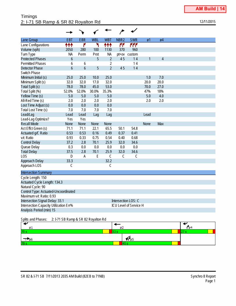
Lane Group EBT EBR WBL WBT NBR2 SWR ø1 ø4Lane ConfigurationsVolume (vph) 2050 280 100 1130 370 960Turn Type NA Perm Prot NA pt+ov customProtected Phases 6 5 2 4 5 1 4 1 4Permitted Phases 6 6 2 1 4Detector Phase 6 6 5 2 4 5 1 4Switch PhaseMinimum Initial (s) 25.0 25.0 10.0 25.0 1.0 7.0Minimum Split (s) 32.0 32.0 17.0 32.0 20.0 20.0Total Split (s) 78.0 78.0 45.0 53.0 70.0 27.0Total Split (%) 52.0% 52.0% 30.0% 35.3% 47% 18%Yellow Time (s) 5.0 5.0 5.0 5.0 5.0 4.0All-Red Time (s) 2.0 2.0 2.0 2.0 2.0 2.0Lost Time Adjust (s) 0.0 0.0 0.0 0.0Total Lost Time (s) 7.0 7.0 7.0 7.0Lead/Lag Lead Lead Lag Lag LeadLead-Lag Optimize? Yes YesRecall Mode None None None None None MaxAct Effct Green (s) 71.1 71.1 22.1 65.5 50.1 54.8Actuated g/C Ratio 0.53 0.53 0.16 0.49 0.37 0.41v/c Ratio 0.93 0.33 0.75 0.54 0.40 0.68Control Delay 37.2 2.8 70.1 25.9 32.0 34.6Queue Delay 0.3 0.0 0.0 0.0 0.0 0.0Total Delay 37.5 2.8 70.1 25.9 32.0 34.6LOS D A E C C CApproach Delay 33.3 32.2Approach LOS C C
Intersection SummaryCycle Length: 150Actuated Cycle Length: 134.3Natural Cycle: 90Control Type: Actuated-UncoordinatedMaximum v/c Ratio: 0.93Intersection Signal Delay: 33.1 Intersection LOS: CIntersection Capacity Utilization Err% ICU Level of Service HAnalysis Period (min) 15
Splits and Phases: 2: I-71 SB Ramp & SR 82 Royalton Rd
AM Build | 14

Intersections
2035 PM

HCS 2010 Signalized Intersection Results Summary
General Information Intersection Information
Agency Hatch Mott MacDonald Duration, h 0.25
Analyst SJT Analysis Date Oct 20, 2015 Area Type Other
Jurisdiction Strongsville Time Period PM PHF 0.92
Intersection SR 82 @ I-71 NB Analysis Year 2035 Analysis Period 1> 7:00
File Name 13_SR82 & I-71 NB 2035 PM.xus
Project Description I-71 / SR 82 IMS
Demand Information EB WB NB SB
Approach Movement L T R L T R L T R L T R
Demand (v), veh/h 1690 1600 330 0 190
Signal Information
GreenYellowRed
44.0 25.0 0.0 0.0 0.0 0.04.0 4.0 0.0 0.0 0.0 0.01.5 1.5 0.0 0.0 0.0 0.0
1 2 3 4
5 6 7
Cycle, s 80.0 Reference Phase 2
Offset, s 0 Reference Point End
Uncoordinated Yes Simult. Gap E/W On
Force Mode Fixed Simult. Gap N/S On
Timer Results EBL EBT WBL WBT NBL NBT SBL SBT
Assigned Phase 2 6 8
Case Number 8.0 8.0 10.0
Phase Duration, s 49.5 49.5 30.5
Change Period, (Y+Rc), s 5.5 5.5 5.5
Max Allow Headway (MAH), s 3.0 3.0 3.3
Queue Clearance Time (gs), s 41.5 21.1 20.0
Green Extension Time (ge), s 2.2 13.7 0.7
Phase Call Probability 1.00 1.00 1.00
Max Out Probability 1.00 0.43 0.41
Movement Group Results EB WB NB SB
Approach Movement L T R L T R L T R L T R
Assigned Movement 2 6 3 8 18
Adjusted Flow Rate (v), veh/h 1837 1739 179 179
Adjusted Saturation Flow Rate (s), veh/h/ln 1756 1675 1740 1740
Queue Service Time (gs), s 39.5 19.1 6.3 6.3
Cycle Queue Clearance Time (gc), s 39.5 19.1 6.3 6.3
Green Ratio (g/C) 0.55 0.55 0.31 0.31
Capacity (c), veh/h 1932 2764 544 544
Volume-to-Capacity Ratio (X) 0.951 0.629 0.330 0.330
Available Capacity (ca), veh/h 1932 2764 544 544
Back of Queue (Q), veh/ln (50th percentile) 16.2 6.2 2.5 2.5
Queue Storage Ratio (RQ) (50th percentile) 0.00 0.00 0.25 0.25
Uniform Delay (d1), s/veh 17.0 12.4 21.1 21.1
Incremental Delay (d2), s/veh 11.0 0.4 0.1 0.1
Initial Queue Delay (d3), s/veh 0.0 0.0 0.0 0.0
Control Delay (d), s/veh 28.0 12.7 21.2 21.2
Level of Service (LOS) C B C C
Approach Delay, s/veh / LOS 28.0 C 12.7 B 31.3 C 0.0
Intersection Delay, s/veh / LOS 22.0 C
Multimodal Results EB WB NB SB
Pedestrian LOS Score / LOS
Bicycle LOS Score / LOS
Copyright © 2015 University of Florida, All Rights Reserved. HCS 2010™ Streets Version 6.50 Generated: 10/26/2015 3:31:32 PM
PM | 13

Timings2: I-71 SB Ramp & SR 82 Royalton Rd 12/11/2015
SR 82 & I-71 SB 7/11/2013 2035 PM No Build Synchro 8 ReportPage 1
Lane Group EBT EBR WBL WBT NBR2 SWR ø1 ø4Lane ConfigurationsVolume (vph) 2030 450 100 1400 840 1850Turn Type NA Perm Prot NA pt+ov customProtected Phases 6 5 2 4 5 1 4 1 4Permitted Phases 6 6 2 1 4Detector Phase 6 6 5 2 4 5 1 4Switch PhaseMinimum Initial (s) 25.0 25.0 10.0 25.0 1.0 7.0Minimum Split (s) 32.0 32.0 17.0 32.0 20.0 20.0Total Split (s) 101.5 101.5 25.0 66.0 60.0 23.5Total Split (%) 67.7% 67.7% 16.7% 44.0% 40% 16%Yellow Time (s) 5.0 5.0 5.0 5.0 5.0 4.0All-Red Time (s) 2.0 2.0 2.0 2.0 2.0 2.0Lost Time Adjust (s) 0.0 0.0 0.0 0.0Total Lost Time (s) 7.0 7.0 7.0 7.0Lead/Lag Lead Lead Lag Lag LeadLead-Lag Optimize? Yes YesRecall Mode None None None None None MaxAct Effct Green (s) 94.5 94.5 18.0 59.5 42.5 76.5Actuated g/C Ratio 0.63 0.63 0.12 0.40 0.28 0.51v/c Ratio 1.33 0.44 1.03 0.82 1.19 1.05Control Delay 177.5 2.6 133.5 44.5 145.1 70.3Queue Delay 0.0 0.0 0.0 0.0 0.0 0.0Total Delay 177.5 2.6 133.5 44.5 145.1 70.3LOS F A F D F EApproach Delay 145.7 54.9Approach LOS F D
Intersection SummaryCycle Length: 150Actuated Cycle Length: 150Natural Cycle: 150Control Type: Actuated-UncoordinatedMaximum v/c Ratio: 1.33Intersection Signal Delay: 104.2 Intersection LOS: FIntersection Capacity Utilization Err% ICU Level of Service HAnalysis Period (min) 15
Splits and Phases: 2: I-71 SB Ramp & SR 82 Royalton Rd
PM No Build | 14

Timings2: I-71 SB Ramp & SR 82 Royalton Rd 12/11/2015
SR 82 & I-71 SB 7/11/2013 2035 PM Build (82EB to 71NB) Synchro 8 ReportPage 1
Lane Group EBT EBR WBL WBT NBR2 SWR ø1 ø4Lane ConfigurationsVolume (vph) 2030 450 100 1400 840 1850Turn Type NA Perm Prot NA pt+ov customProtected Phases 6 5 2 4 5 1 4 1 4Permitted Phases 6 6 2 1 4Detector Phase 6 6 5 2 4 5 1 4Switch PhaseMinimum Initial (s) 25.0 25.0 10.0 25.0 1.0 7.0Minimum Split (s) 32.0 32.0 17.0 32.0 20.0 20.0Total Split (s) 82.0 82.0 40.0 62.0 60.0 28.0Total Split (%) 54.7% 54.7% 26.7% 41.3% 40% 19%Yellow Time (s) 5.0 5.0 5.0 5.0 5.0 4.0All-Red Time (s) 2.0 2.0 2.0 2.0 2.0 2.0Lost Time Adjust (s) 0.0 0.0 0.0 0.0Total Lost Time (s) 7.0 7.0 7.0 7.0Lead/Lag Lead Lead Lag Lag LeadLead-Lag Optimize? Yes YesRecall Mode None None None None None MaxAct Effct Green (s) 75.0 75.0 33.0 55.0 62.0 81.0Actuated g/C Ratio 0.50 0.50 0.22 0.37 0.41 0.54v/c Ratio 0.97 0.49 0.56 0.88 0.82 0.99Control Delay 49.1 3.3 58.6 51.2 46.2 51.8Queue Delay 6.3 0.0 0.0 0.0 0.0 0.0Total Delay 55.4 3.3 58.6 51.2 46.2 51.8LOS E A E D D DApproach Delay 45.9 52.1Approach LOS D D
Intersection SummaryCycle Length: 150Actuated Cycle Length: 150Natural Cycle: 90Control Type: Actuated-UncoordinatedMaximum v/c Ratio: 0.99Intersection Signal Delay: 49.0 Intersection LOS: DIntersection Capacity Utilization Err% ICU Level of Service HAnalysis Period (min) 15
Splits and Phases: 2: I-71 SB Ramp & SR 82 Royalton Rd
PM Build | 14

SR 82 Corridor

No Build
2035 AM

Timings1: I-71 NB Off Ramp 10/23/2015
SR 82 Royalton Road 11/9/2012 AM 2035 No Build Optimized Timings Synchro 8 ReportPage 1
Lane Group EBT WBT NBLLane ConfigurationsVolume (vph) 730 2040 290Turn Type NA NA ProtProtected Phases 2 6 8Permitted PhasesDetector Phase 2 6 8Switch PhaseMinimum Initial (s) 32.0 32.0 10.0Minimum Split (s) 53.0 38.0 20.0Total Split (s) 102.0 102.0 48.0Total Split (%) 68.0% 68.0% 32.0%Yellow Time (s) 3.6 3.6 3.0All-Red Time (s) 2.2 2.2 3.0Lost Time Adjust (s) -1.4 -2.0 -1.4Total Lost Time (s) 4.4 3.8 4.6Lead/LagLead-Lag Optimize?Recall Mode C-Max C-Max NoneAct Effct Green (s) 109.1 109.7 31.9Actuated g/C Ratio 0.73 0.73 0.21v/c Ratio 0.31 0.61 0.81Control Delay 4.7 11.1 61.8Queue Delay 0.0 0.0 0.0Total Delay 4.7 11.1 61.8LOS A B EApproach Delay 4.7 11.1 61.8Approach LOS A B E
Intersection SummaryCycle Length: 150Actuated Cycle Length: 150Offset: 42 (28%), Referenced to phase 2:EBT and 6:WBT, Start of YellowNatural Cycle: 75Control Type: Actuated-CoordinatedMaximum v/c Ratio: 0.81Intersection Signal Delay: 17.9 Intersection LOS: BIntersection Capacity Utilization 58.6% ICU Level of Service BAnalysis Period (min) 15
Splits and Phases: 1: I-71 NB Off Ramp

Timings2: I-71 SB Ramp & SR 82 Royalton Rd 10/23/2015
SR 82 Royalton Road 11/9/2012 AM 2035 No Build Optimized Timings Synchro 8 ReportPage 2
Lane Group EBT EBR WBL WBT NBR2 SWR ø1 ø4Lane ConfigurationsVolume (vph) 2050 280 100 1130 370 960Turn Type NA custom Prot NA pt+ov customProtected Phases 6 7 5 2 4 5 1 4 1 4Permitted Phases 6 6 7 2 1 4Detector Phase 6 7 5 2 4 5 1 4Switch PhaseMinimum Initial (s) 25.0 4.0 10.0 25.0 1.0 7.0Minimum Split (s) 32.0 10.6 17.0 32.0 20.0 20.0Total Split (s) 110.0 20.0 20.0 80.0 50.0 20.0Total Split (%) 73.3% 13.3% 13.3% 53.3% 33% 13%Yellow Time (s) 3.6 3.6 3.6 3.6 3.6 3.0All-Red Time (s) 3.0 3.0 3.0 3.0 3.0 3.0Lost Time Adjust (s) 0.0 0.0 0.0 0.0Total Lost Time (s) 6.6 6.6 6.6 6.6Lead/Lag Lead Lag Lag LeadLead-Lag Optimize?Recall Mode None None None C-Max None MaxAct Effct Green (s) 103.4 123.4 13.4 75.9 34.0 60.9Actuated g/C Ratio 0.69 0.82 0.09 0.51 0.23 0.41v/c Ratio 1.14 0.27 0.85 0.58 0.67 0.80Control Delay 91.9 2.9 96.8 22.0 58.8 43.9Queue Delay 0.0 0.0 0.0 0.2 0.0 0.0Total Delay 91.9 2.9 96.8 22.2 58.8 43.9LOS F A F C E DApproach Delay 80.2 28.3Approach LOS F C
Intersection SummaryCycle Length: 150Actuated Cycle Length: 150Offset: 148 (99%), Referenced to phase 2:WBT, Start of YellowNatural Cycle: 150Control Type: Actuated-CoordinatedMaximum v/c Ratio: 1.14Intersection Signal Delay: 57.7 Intersection LOS: EIntersection Capacity Utilization Err% ICU Level of Service HAnalysis Period (min) 15
Splits and Phases: 2: I-71 SB Ramp & SR 82 Royalton Rd

Timings3: Howe Road & SR 82 Royalton Rd 10/23/2015
SR 82 Royalton Road 11/9/2012 AM 2035 No Build Optimized Timings Synchro 8 ReportPage 3
Lane Group EBL EBT WBL WBT WBR NBL NBT NBR SBL SBT SBRLane ConfigurationsVolume (vph) 30 1400 420 1620 50 120 30 890 40 10 10Turn Type Prot NA Prot NA pm+ov Split NA pm+ov Split NA pm+ovProtected Phases 5 2 1 6 4 8 8 1 4 4 5Permitted Phases 6 8 4Detector Phase 5 2 1 6 4 8 8 1 4 4 5Switch PhaseMinimum Initial (s) 4.0 27.0 10.0 27.0 10.0 10.0 10.0 10.0 10.0 10.0 4.0Minimum Split (s) 8.0 40.6 16.0 46.6 41.6 20.0 20.0 16.0 41.6 41.6 8.0Total Split (s) 19.0 73.0 30.0 84.0 17.0 30.0 30.0 30.0 17.0 17.0 19.0Total Split (%) 12.7% 48.7% 20.0% 56.0% 11.3% 20.0% 20.0% 20.0% 11.3% 11.3% 12.7%Yellow Time (s) 3.5 3.6 3.0 3.6 3.6 3.6 3.6 3.0 3.6 3.6 3.5All-Red Time (s) 0.5 3.0 3.0 3.0 3.0 3.0 3.0 3.0 3.0 3.0 0.5Lost Time Adjust (s) -2.0 -2.0 -2.0 -2.0 -2.0 -1.6 -1.6 -1.6 -1.6 -1.6 -1.6Total Lost Time (s) 2.0 4.6 4.0 4.6 4.6 5.0 5.0 4.4 5.0 5.0 2.4Lead/Lag Lag Lag Lead Lead Lead LagLead-Lag Optimize?Recall Mode None C-Max None C-Max None None None None None None NoneAct Effct Green (s) 15.1 68.4 35.5 92.7 105.6 15.9 15.9 56.0 11.6 11.6 30.8Actuated g/C Ratio 0.10 0.46 0.24 0.62 0.70 0.11 0.11 0.37 0.08 0.08 0.21v/c Ratio 0.11 1.42 0.64 0.86 0.05 0.55 0.55 1.33 0.18 0.18 0.05Control Delay 53.2 225.0 58.8 28.8 1.0 74.6 74.2 194.9 66.6 68.0 0.2Queue Delay 0.0 0.0 0.0 0.0 0.0 0.0 0.0 0.0 0.0 0.0 0.0Total Delay 53.2 225.0 58.8 28.8 1.0 74.6 74.2 194.9 66.6 68.0 0.2LOS D F E C A E E F E E AApproach Delay 221.4 34.4 174.2 51.9Approach LOS F C F D
Intersection SummaryCycle Length: 150Actuated Cycle Length: 150Offset: 0 (0%), Referenced to phase 2:EBT and 6:WBT, Start of YellowNatural Cycle: 150Control Type: Actuated-CoordinatedMaximum v/c Ratio: 1.42Intersection Signal Delay: 125.4 Intersection LOS: FIntersection Capacity Utilization 79.5% ICU Level of Service DAnalysis Period (min) 15
Splits and Phases: 3: Howe Road & SR 82 Royalton Rd

No Build
2035 PM

Timings1: I-71 NB Off Ramp 10/23/2015
SR 82 Royalton Road 11/9/2012 PM 2035 No Build Optimized Timing Synchro 8 ReportPage 1
Lane Group EBT WBT NBLLane ConfigurationsVolume (vph) 1690 1600 330Turn Type NA NA ProtProtected Phases 2 6 8Permitted PhasesDetector Phase 2 6 8Switch PhaseMinimum Initial (s) 32.0 32.0 10.0Minimum Split (s) 53.0 38.0 20.0Total Split (s) 107.0 107.0 43.0Total Split (%) 71.3% 71.3% 28.7%Yellow Time (s) 3.6 3.6 3.0All-Red Time (s) 2.2 2.2 3.0Lost Time Adjust (s) -1.4 -2.0 -1.4Total Lost Time (s) 4.4 3.8 4.6Lead/LagLead-Lag Optimize?Recall Mode C-Max C-Max NoneAct Effct Green (s) 108.0 108.6 33.0Actuated g/C Ratio 0.72 0.72 0.22v/c Ratio 0.73 0.47 0.84Control Delay 7.2 9.6 63.7Queue Delay 0.0 0.0 0.0Total Delay 7.2 9.6 63.7LOS A A EApproach Delay 7.2 9.6 63.7Approach LOS A A E
Intersection SummaryCycle Length: 150Actuated Cycle Length: 150Offset: 136 (91%), Referenced to phase 2:EBT and 6:WBT, Start of YellowNatural Cycle: 75Control Type: Actuated-CoordinatedMaximum v/c Ratio: 0.84Intersection Signal Delay: 16.5 Intersection LOS: BIntersection Capacity Utilization 69.6% ICU Level of Service CAnalysis Period (min) 15
Splits and Phases: 1: I-71 NB Off Ramp

Timings2: I-71 SB Ramp & SR 82 Royalton Rd 10/23/2015
SR 82 Royalton Road 11/9/2012 PM 2035 No Build Optimized Timing Synchro 8 ReportPage 2
Lane Group EBT EBR WBL WBT NBR2 SWR ø1 ø4Lane ConfigurationsVolume (vph) 2030 450 100 1400 840 1850Turn Type NA Perm Prot NA pt+ov customProtected Phases 6 5 2 4 5 1 4 1 4Permitted Phases 6 6 2 1 4Detector Phase 6 6 5 2 4 5 1 4Switch PhaseMinimum Initial (s) 25.0 25.0 10.0 25.0 1.0 7.0Minimum Split (s) 32.0 32.0 17.0 32.0 20.0 20.0Total Split (s) 101.0 101.0 23.0 62.0 62.0 26.0Total Split (%) 67.3% 67.3% 15.3% 41.3% 41% 17%Yellow Time (s) 3.6 3.6 3.6 3.6 3.6 3.0All-Red Time (s) 3.0 3.0 3.0 3.0 3.0 3.0Lost Time Adjust (s) 0.0 0.0 0.0 0.0Total Lost Time (s) 6.6 6.6 6.6 6.6Lead/Lag Lead Lead Lag Lag LeadLead-Lag Optimize?Recall Mode None None None C-Max None MaxAct Effct Green (s) 94.4 94.4 16.4 55.4 43.0 81.4Actuated g/C Ratio 0.63 0.63 0.11 0.37 0.29 0.54v/c Ratio 1.33 0.44 1.14 0.88 1.18 0.98Control Delay 167.8 0.3 154.2 40.9 139.7 50.4Queue Delay 0.0 0.0 0.0 0.0 0.0 40.6Total Delay 167.8 0.3 154.2 40.9 139.7 91.0LOS F A F D F FApproach Delay 137.4 54.3Approach LOS F D
Intersection SummaryCycle Length: 150Actuated Cycle Length: 150Offset: 86 (57%), Referenced to phase 2:WBT, Start of YellowNatural Cycle: 150Control Type: Actuated-CoordinatedMaximum v/c Ratio: 1.33Intersection Signal Delay: 105.5 Intersection LOS: FIntersection Capacity Utilization Err% ICU Level of Service HAnalysis Period (min) 15
Splits and Phases: 2: I-71 SB Ramp & SR 82 Royalton Rd

Timings3: Howe Road & SR 82 Royalton Rd 10/23/2015
SR 82 Royalton Road 11/9/2012 PM 2035 No Build Optimized Timing Synchro 8 ReportPage 3
Lane Group EBL EBT WBL WBT WBR NBL NBT NBR SBL SBT SBRLane ConfigurationsVolume (vph) 190 1640 930 1930 390 170 100 630 210 150 270Turn Type Prot NA Prot NA pm+ov Split NA pm+ov Split NA pm+ovProtected Phases 5 2 1 6 4 8 8 1 4 4 5Permitted Phases 6 8 4Detector Phase 5 2 1 6 4 8 8 1 4 4 5Switch PhaseMinimum Initial (s) 7.0 27.0 10.0 27.0 10.0 10.0 10.0 10.0 10.0 10.0 7.0Minimum Split (s) 13.0 40.6 16.0 46.6 41.6 20.0 20.0 16.0 41.6 41.6 13.0Total Split (s) 16.0 64.0 39.0 87.0 23.0 24.0 24.0 39.0 23.0 23.0 16.0Total Split (%) 10.7% 42.7% 26.0% 58.0% 15.3% 16.0% 16.0% 26.0% 15.3% 15.3% 10.7%Yellow Time (s) 3.0 3.6 3.0 3.6 3.6 3.6 3.6 3.0 3.6 3.6 3.0All-Red Time (s) 3.0 3.0 3.0 3.0 3.0 3.0 3.0 3.0 3.0 3.0 3.0Lost Time Adjust (s) -2.0 -2.0 -2.0 -2.0 -2.0 -1.6 -1.6 -1.6 -1.6 -1.6 -1.6Total Lost Time (s) 4.0 4.6 4.0 4.6 4.6 5.0 5.0 4.4 5.0 5.0 4.4Lead/Lag Lag Lag Lead Lead Lead LagLead-Lag Optimize?Recall Mode None C-Max None C-Max None None None None None None NoneAct Effct Green (s) 12.0 59.4 35.8 83.2 101.3 18.5 18.5 58.9 17.7 17.7 34.3Actuated g/C Ratio 0.08 0.40 0.24 0.55 0.68 0.12 0.12 0.39 0.12 0.12 0.23v/c Ratio 0.79 1.41 1.42 1.03 0.49 0.84 0.49 0.63 0.64 0.82 0.86Control Delay 71.7 218.2 232.2 56.7 4.7 94.5 69.1 40.1 70.9 92.0 57.1Queue Delay 0.0 0.0 0.0 26.6 0.0 0.0 0.0 0.0 0.0 0.0 0.2Total Delay 71.7 218.2 232.2 83.3 4.7 94.5 69.1 40.1 70.9 92.0 57.3LOS E F F F A F E D E F EApproach Delay 204.8 117.5 53.5 69.1Approach LOS F F D E
Intersection SummaryCycle Length: 150Actuated Cycle Length: 150Offset: 28 (19%), Referenced to phase 2:EBT and 6:WBT, Start of YellowNatural Cycle: 145Control Type: Actuated-CoordinatedMaximum v/c Ratio: 1.42Intersection Signal Delay: 130.4 Intersection LOS: FIntersection Capacity Utilization 93.2% ICU Level of Service FAnalysis Period (min) 15
Splits and Phases: 3: Howe Road & SR 82 Royalton Rd

Build
2035 AM

Timings1: I-71 NB Off Ramp 12/10/2015
SR 82 Royalton Road 11/9/2012 AM 2035 Build Optimized Timings Synchro 9 ReportPage 1
Lane Group EBT EBR WBT NBL2 NBLLane ConfigurationsTraffic Volume (vph) 730 1690 940 290 0Future Volume (vph) 730 1690 940 290 0Turn Type NA Free NA Prot PermProtected Phases 2 6 8Permitted Phases Free 8Detector Phase 2 6 8 8Switch PhaseMinimum Initial (s) 32.0 32.0 10.0 10.0Minimum Split (s) 53.0 38.0 20.0 20.0Total Split (s) 102.0 102.0 48.0 48.0Total Split (%) 68.0% 68.0% 32.0% 32.0%Yellow Time (s) 3.6 3.6 3.0 3.0All-Red Time (s) 2.2 2.2 3.0 3.0Lost Time Adjust (s) -1.4 -2.0 -1.4 0.0Total Lost Time (s) 4.4 3.8 4.6 6.0Lead/LagLead-Lag Optimize?Recall Mode C-Max C-Max None NoneAct Effct Green (s) 107.2 150.0 107.8 33.8 32.4Actuated g/C Ratio 0.71 1.00 0.72 0.23 0.22v/c Ratio 0.75 0.65 1.03dr 0.82 0.77Control Delay 8.7 5.7 13.5 72.1 61.2Queue Delay 0.0 0.0 0.0 0.0 0.0Total Delay 8.7 5.7 13.5 72.1 61.2LOS A A B E EApproach Delay 7.6 13.5 66.9Approach LOS A B E
Intersection SummaryCycle Length: 150Actuated Cycle Length: 150Offset: 95 (63%), Referenced to phase 2:EBT and 6:WBT, Start of YellowNatural Cycle: 75Control Type: Actuated-CoordinatedMaximum v/c Ratio: 0.82Intersection Signal Delay: 16.4 Intersection LOS: BIntersection Capacity Utilization 62.9% ICU Level of Service BAnalysis Period (min) 15dr Defacto Right Lane. Recode with 1 though lane as a right lane.
Splits and Phases: 1: I-71 NB Off Ramp

Timings2: I-71 SB Ramp & SR 82 Royalton Rd 12/10/2015
SR 82 Royalton Road 11/9/2012 AM 2035 Build Optimized Timings Synchro 9 ReportPage 2
Lane Group EBT EBR WBL WBT NBR2 SWR ø1 ø4Lane ConfigurationsTraffic Volume (vph) 2050 280 100 1130 370 960Future Volume (vph) 2050 280 100 1130 370 960Turn Type NA custom Prot NA pt+ov customProtected Phases 6 7 5 2 4 5 1 4 1 4Permitted Phases 6 6 7 2 1 4Detector Phase 6 7 5 2 4 5 1 4Switch PhaseMinimum Initial (s) 25.0 4.0 10.0 25.0 1.0 7.0Minimum Split (s) 32.0 10.6 17.0 32.0 20.0 20.0Total Split (s) 110.0 20.0 20.0 80.0 50.0 20.0Total Split (%) 73.3% 13.3% 13.3% 53.3% 33% 13%Yellow Time (s) 3.6 3.6 3.6 3.6 3.6 3.0All-Red Time (s) 3.0 3.0 3.0 3.0 3.0 3.0Lost Time Adjust (s) 0.0 0.0 0.0 0.0Total Lost Time (s) 6.6 6.6 6.6 6.6Lead/Lag Lead Lag Lag LeadLead-Lag Optimize?Recall Mode None None None C-Max None MaxAct Effct Green (s) 103.4 123.4 13.4 78.9 34.0 57.9Actuated g/C Ratio 0.69 0.82 0.09 0.53 0.23 0.39v/c Ratio 0.73 0.27 0.85 0.55 0.67 0.74Control Delay 8.8 1.7 100.2 26.1 58.8 42.6Queue Delay 0.2 0.0 0.0 0.0 0.0 0.2Total Delay 9.0 1.7 100.2 26.1 58.8 42.8LOS A A F C E DApproach Delay 8.0 32.3Approach LOS A C
Intersection SummaryCycle Length: 150Actuated Cycle Length: 150Offset: 149 (99%), Referenced to phase 2:WBT, Start of YellowNatural Cycle: 90Control Type: Actuated-CoordinatedMaximum v/c Ratio: 0.85Intersection Signal Delay: 24.9 Intersection LOS: CIntersection Capacity Utilization Err% ICU Level of Service HAnalysis Period (min) 15
Splits and Phases: 2: I-71 SB Ramp & SR 82 Royalton Rd

Timings3: Howe Road & SR 82 Royalton Rd 12/10/2015
SR 82 Royalton Road 11/9/2012 AM 2035 Build Optimized Timings Synchro 9 ReportPage 3
Lane Group EBL EBT WBL WBT WBR NBL NBT NBR SBL SBT SBRLane ConfigurationsTraffic Volume (vph) 30 1400 420 1620 50 120 30 890 40 10 10Future Volume (vph) 30 1400 420 1620 50 120 30 890 40 10 10Turn Type Prot NA Prot NA pm+ov Split NA pm+ov Split NA pm+ovProtected Phases 5 2 1 6 4 8 8 1 4 4 5Permitted Phases 6 8 4Detector Phase 5 2 1 6 4 8 8 1 4 4 5Switch PhaseMinimum Initial (s) 4.0 27.0 10.0 27.0 10.0 10.0 10.0 10.0 10.0 10.0 4.0Minimum Split (s) 8.0 40.6 16.0 46.6 41.6 20.0 20.0 16.0 41.6 41.6 8.0Total Split (s) 19.0 73.0 30.0 84.0 17.0 30.0 30.0 30.0 17.0 17.0 19.0Total Split (%) 12.7% 48.7% 20.0% 56.0% 11.3% 20.0% 20.0% 20.0% 11.3% 11.3% 12.7%Yellow Time (s) 3.5 3.6 3.0 3.6 3.6 3.6 3.6 3.0 3.6 3.6 3.5All-Red Time (s) 0.5 3.0 3.0 3.0 3.0 3.0 3.0 3.0 3.0 3.0 0.5Lost Time Adjust (s) -2.0 -2.0 -2.0 -2.0 -2.0 -1.6 -1.6 -1.6 -1.6 -1.6 -1.6Total Lost Time (s) 2.0 4.6 4.0 4.6 4.6 5.0 5.0 4.4 5.0 5.0 2.4Lead/Lag Lag Lag Lead Lead Lead LagLead-Lag Optimize?Recall Mode None C-Max None C-Max None None None None None None NoneAct Effct Green (s) 15.1 68.5 35.4 92.7 105.6 15.9 15.9 55.9 11.6 11.6 30.8Actuated g/C Ratio 0.10 0.46 0.24 0.62 0.70 0.11 0.11 0.37 0.08 0.08 0.21v/c Ratio 0.11 0.83 0.64 0.86 0.06 0.55 0.55 0.92 0.18 0.18 0.05Control Delay 55.1 34.7 50.5 23.5 0.9 74.6 74.2 59.5 66.6 68.0 0.2Queue Delay 0.0 0.0 0.0 0.0 0.0 0.0 0.0 0.0 0.0 0.0 0.0Total Delay 55.1 34.7 50.5 23.5 0.9 74.6 74.2 59.5 66.6 68.0 0.2LOS E C D C A E E E E E AApproach Delay 35.2 28.6 62.1 51.9Approach LOS D C E D
Intersection SummaryCycle Length: 150Actuated Cycle Length: 150Offset: 114 (76%), Referenced to phase 2:EBT and 6:WBT, Start of YellowNatural Cycle: 150Control Type: Actuated-CoordinatedMaximum v/c Ratio: 0.92Intersection Signal Delay: 38.2 Intersection LOS: DIntersection Capacity Utilization 79.5% ICU Level of Service DAnalysis Period (min) 15
Splits and Phases: 3: Howe Road & SR 82 Royalton Rd

Build
2035 PM

Timings1: I-71 NB Off Ramp 12/10/2015
SR 82 Royalton Road 11/9/2012 PM 2035 Build Optimized Timing Synchro 8 ReportPage 1
Lane Group EBT EBR WBT NBL2 NBLLane ConfigurationsTraffic Volume (vph) 1690 1180 1180 330 0Future Volume (vph) 1690 1180 1180 330 0Turn Type NA Free NA Prot PermProtected Phases 2 6 8Permitted Phases Free 8Detector Phase 2 6 8 8Switch PhaseMinimum Initial (s) 32.0 32.0 10.0 10.0Minimum Split (s) 53.0 38.0 20.0 20.0Total Split (s) 107.0 107.0 43.0 43.0Total Split (%) 71.3% 71.3% 28.7% 28.7%Yellow Time (s) 3.6 3.6 3.0 3.0All-Red Time (s) 2.2 2.2 3.0 3.0Lost Time Adjust (s) -1.4 -2.0 -1.4 0.0Total Lost Time (s) 4.4 3.8 4.6 6.0Lead/LagLead-Lag Optimize?Recall Mode C-Max C-Max None NoneAct Effct Green (s) 107.0 150.0 107.6 34.0 32.6Actuated g/C Ratio 0.71 1.00 0.72 0.23 0.22v/c Ratio 0.92 0.67 0.50 0.87 0.83Control Delay 18.0 9.5 10.4 78.0 70.4Queue Delay 0.2 0.0 0.0 0.0 0.0Total Delay 18.2 9.5 10.4 78.0 70.4LOS B A B E EApproach Delay 15.5 10.4 74.4Approach LOS B B E
Intersection SummaryCycle Length: 150Actuated Cycle Length: 150Offset: 127 (85%), Referenced to phase 2:EBT and 6:WBT, Start of YellowNatural Cycle: 90Control Type: Actuated-CoordinatedMaximum v/c Ratio: 0.92Intersection Signal Delay: 20.5 Intersection LOS: CIntersection Capacity Utilization 82.9% ICU Level of Service EAnalysis Period (min) 15
Splits and Phases: 1: I-71 NB Off Ramp

Timings2: I-71 SB Ramp & SR 82 Royalton Rd 12/10/2015
SR 82 Royalton Road 11/9/2012 PM 2035 Build Optimized Timing Synchro 8 ReportPage 2
Lane Group EBT EBR WBL WBT NBR2 SWR ø1 ø4Lane ConfigurationsTraffic Volume (vph) 2030 450 100 1400 840 1850Future Volume (vph) 2030 450 100 1400 840 1850Turn Type NA Perm Prot NA pt+ov customProtected Phases 6 5 2 4 5 1 4 1 4Permitted Phases 6 6 2 1 4Detector Phase 6 6 5 2 4 5 1 4Switch PhaseMinimum Initial (s) 25.0 25.0 10.0 25.0 1.0 7.0Minimum Split (s) 32.0 32.0 17.0 32.0 20.0 20.0Total Split (s) 101.0 101.0 23.0 62.0 62.0 26.0Total Split (%) 67.3% 67.3% 15.3% 41.3% 41% 17%Yellow Time (s) 3.6 3.6 3.6 3.6 3.6 3.0All-Red Time (s) 3.0 3.0 3.0 3.0 3.0 3.0Lost Time Adjust (s) 0.0 0.0 0.0 0.0Total Lost Time (s) 6.6 6.6 6.6 6.6Lead/Lag Lead Lead Lag Lag LeadLead-Lag Optimize?Recall Mode None None None C-Max None MaxAct Effct Green (s) 94.4 94.4 16.4 55.8 43.0 81.0Actuated g/C Ratio 0.63 0.63 0.11 0.37 0.29 0.54v/c Ratio 0.77 0.44 1.14 0.87 1.18 0.87Control Delay 9.8 0.3 153.8 40.8 139.7 35.7Queue Delay 0.8 0.0 0.0 0.0 0.0 29.9Total Delay 10.6 0.3 153.8 40.8 139.7 65.6LOS B A F D F EApproach Delay 8.8 54.1Approach LOS A D
Intersection SummaryCycle Length: 150Actuated Cycle Length: 150Offset: 74 (49%), Referenced to phase 2:WBT, Start of YellowNatural Cycle: 90Control Type: Actuated-CoordinatedMaximum v/c Ratio: 1.18Intersection Signal Delay: 50.5 Intersection LOS: DIntersection Capacity Utilization Err% ICU Level of Service HAnalysis Period (min) 15
Splits and Phases: 2: I-71 SB Ramp & SR 82 Royalton Rd

Timings3: Howe Road & SR 82 Royalton Rd 12/10/2015
SR 82 Royalton Road 11/9/2012 PM 2035 Build Optimized Timing Synchro 8 ReportPage 3
Lane Group EBL EBT WBL WBT WBR NBL NBT NBR SBL SBT SBRLane ConfigurationsTraffic Volume (vph) 190 1640 930 1930 390 170 100 630 210 150 270Future Volume (vph) 190 1640 930 1930 390 170 100 630 210 150 270Turn Type Prot NA Prot NA pm+ov Split NA pm+ov Split NA pm+ovProtected Phases 5 2 1 6 4 8 8 1 4 4 5Permitted Phases 6 8 4Detector Phase 5 2 1 6 4 8 8 1 4 4 5Switch PhaseMinimum Initial (s) 7.0 27.0 10.0 27.0 10.0 10.0 10.0 10.0 10.0 10.0 7.0Minimum Split (s) 13.0 40.6 16.0 46.6 41.6 20.0 20.0 16.0 41.6 41.6 13.0Total Split (s) 16.0 64.0 39.0 87.0 23.0 24.0 24.0 39.0 23.0 23.0 16.0Total Split (%) 10.7% 42.7% 26.0% 58.0% 15.3% 16.0% 16.0% 26.0% 15.3% 15.3% 10.7%Yellow Time (s) 3.0 3.6 3.0 3.6 3.6 3.6 3.6 3.0 3.6 3.6 3.0All-Red Time (s) 3.0 3.0 3.0 3.0 3.0 3.0 3.0 3.0 3.0 3.0 3.0Lost Time Adjust (s) -2.0 -2.0 -2.0 -2.0 -2.0 -1.6 -1.6 -1.6 -1.6 -1.6 -1.6Total Lost Time (s) 4.0 4.6 4.0 4.6 4.6 5.0 5.0 4.4 5.0 5.0 4.4Lead/Lag Lag Lag Lead Lead Lead LagLead-Lag Optimize?Recall Mode None C-Max None C-Max None None None None None None NoneAct Effct Green (s) 12.0 59.4 35.8 83.2 101.3 18.5 18.5 58.9 17.7 17.7 34.3Actuated g/C Ratio 0.08 0.40 0.24 0.55 0.68 0.12 0.12 0.39 0.12 0.12 0.23v/c Ratio 0.79 1.15 1.42 1.03 0.49 0.84 0.49 0.63 0.64 0.82 0.86Control Delay 70.7 103.6 233.8 55.3 5.5 94.5 69.1 40.1 71.0 92.0 57.1Queue Delay 0.0 0.0 0.0 26.5 0.0 0.0 0.0 0.0 0.0 0.0 0.3Total Delay 70.7 103.6 233.8 81.9 5.5 94.5 69.1 40.1 71.0 92.0 57.4LOS E F F F A F E D E F EApproach Delay 100.6 117.4 53.5 69.2Approach LOS F F D E
Intersection SummaryCycle Length: 150Actuated Cycle Length: 150Offset: 6 (4%), Referenced to phase 2:EBT and 6:WBT, Start of YellowNatural Cycle: 145Control Type: Actuated-CoordinatedMaximum v/c Ratio: 1.42Intersection Signal Delay: 99.3 Intersection LOS: FIntersection Capacity Utilization 93.2% ICU Level of Service FAnalysis Period (min) 15
Splits and Phases: 3: Howe Road & SR 82 Royalton Rd

Freeway Segments
2035 AM

BASIC FREEWAY SEGMENTS WORKSHEET
General Information Site Information Analyst SJT Highway/Direction of Travel NB Agency or Company Hatch Mott MacDonald From/To @ SR 303 Date Performed 5/27/2015 JurisdictionAnalysis Time Period AM Analysis Year 2035
Project Description I-71 / SR 82 IMS
Oper.(LOS) Des.(N) Planning Data
Flow Inputs
Volume, V 3620 veh/h Peak-Hour Factor, PHF 0.94 AADT veh/day %Trucks and Buses, PT 4
Peak-Hr Prop. of AADT, K %RVs, PR 0 Peak-Hr Direction Prop, D General Terrain: Level DDHV = AADT x K x D veh/h Grade % Length mi
Up/Down %
Calculate Flow Adjustments
fp 1.00 ER 1.2
ET 1.5 fHV = 1/[1+PT(ET - 1) + PR(ER - 1)] 0.980
Speed Inputs Calc Speed Adj and FFS
Lane Width ft
Rt-Side Lat. Clearance ft
Number of Lanes, N 3
Total Ramp Density, TRD ramps/mi
FFS (measured) 65.0 mph
Base free-flow Speed, BFFS mph
fLW mph
fLC mph
TRD Adjustment mph
FFS 65.0 mph
LOS and Performance Measures Design (N)
Operational (LOS)vp = (V or DDHV) / (PHF x N x fHV x fp) 1309 pc/h/ln
S 65.0 mph
D = vp / S 20.1 pc/mi/ln
LOS C
Design (N)
Design LOSvp = (V or DDHV) / (PHF x N x fHV x fp) pc/h/ln
S mph
D = vp / S pc/mi/ln
Required Number of Lanes, N
Glossary Factor Location
N - Number of lanes S - Speed
V - Hourly volume D - Densityvp - Flow rate FFS - Free-flow speed
LOS - Level of service BFFS - Base free-flow speed
DDHV - Directional design hour volume
ER - Exhibits 11-10, 11-12 fLW - Exhibit 11-8
ET - Exhibits 11-10, 11-11, 11-13 fLC - Exhibit 11-9
fp - Page 11-18 TRD - Page 11-11
LOS, S, FFS, vp - Exhibits 11-2, 11-3
Copyright © 2013 University of Florida, All Rights Reserved HCS 2010TM Version 6.50 Generated: 10/26/2015 2:44 PM
Page 1 of 1BASIC FREEWAY WORKSHEET
10/26/2015file:///C:/Users/bob64314/AppData/Local/Temp/f2k50A8.tmp
AM | 02

BASIC FREEWAY SEGMENTS WORKSHEET
General Information Site Information Analyst SJT Highway/Direction of Travel NB Agency or Company Hatch Mott MacDonald From/To SR 303 to SR 82 Date Performed 5/27/2015 JurisdictionAnalysis Time Period AM Analysis Year 2035
Project Description I-71 / SR 82 IMS
Oper.(LOS) Des.(N) Planning Data
Flow Inputs
Volume, V 3920 veh/h Peak-Hour Factor, PHF 0.94 AADT veh/day %Trucks and Buses, PT 4
Peak-Hr Prop. of AADT, K %RVs, PR 0 Peak-Hr Direction Prop, D General Terrain: Level DDHV = AADT x K x D veh/h Grade % Length mi
Up/Down %
Calculate Flow Adjustments
fp 1.00 ER 1.2
ET 1.5 fHV = 1/[1+PT(ET - 1) + PR(ER - 1)] 0.980
Speed Inputs Calc Speed Adj and FFS
Lane Width ft
Rt-Side Lat. Clearance ft
Number of Lanes, N 3
Total Ramp Density, TRD ramps/mi
FFS (measured) 65.0 mph
Base free-flow Speed, BFFS mph
fLW mph
fLC mph
TRD Adjustment mph
FFS 65.0 mph
LOS and Performance Measures Design (N)
Operational (LOS)vp = (V or DDHV) / (PHF x N x fHV x fp) 1418 pc/h/ln
S 65.0 mph
D = vp / S 21.8 pc/mi/ln
LOS C
Design (N)
Design LOSvp = (V or DDHV) / (PHF x N x fHV x fp) pc/h/ln
S mph
D = vp / S pc/mi/ln
Required Number of Lanes, N
Glossary Factor Location
N - Number of lanes S - Speed
V - Hourly volume D - Densityvp - Flow rate FFS - Free-flow speed
LOS - Level of service BFFS - Base free-flow speed
DDHV - Directional design hour volume
ER - Exhibits 11-10, 11-12 fLW - Exhibit 11-8
ET - Exhibits 11-10, 11-11, 11-13 fLC - Exhibit 11-9
fp - Page 11-18 TRD - Page 11-11
LOS, S, FFS, vp - Exhibits 11-2, 11-3
Copyright © 2013 University of Florida, All Rights Reserved HCS 2010TM Version 6.50 Generated: 10/26/2015 2:45 PM
Page 1 of 1BASIC FREEWAY WORKSHEET
10/26/2015file:///C:/Users/bob64314/AppData/Local/Temp/f2kD2E8.tmp
AM | 04

BASIC FREEWAY SEGMENTS WORKSHEET
General Information Site Information Analyst SJT Highway/Direction of Travel NB Agency or Company Hatch Mott MacDonald From/To @ SR 82 EB Date Performed 5/27/2015 JurisdictionAnalysis Time Period AM Analysis Year 2035
Project Description I-71 / SR 82 IMS
Oper.(LOS) Des.(N) Planning Data
Flow Inputs
Volume, V 3510 veh/h Peak-Hour Factor, PHF 0.94 AADT veh/day %Trucks and Buses, PT 4
Peak-Hr Prop. of AADT, K %RVs, PR 0 Peak-Hr Direction Prop, D General Terrain: Level DDHV = AADT x K x D veh/h Grade % Length mi
Up/Down %
Calculate Flow Adjustments
fp 1.00 ER 1.2
ET 1.5 fHV = 1/[1+PT(ET - 1) + PR(ER - 1)] 0.980
Speed Inputs Calc Speed Adj and FFS
Lane Width ft
Rt-Side Lat. Clearance ft
Number of Lanes, N 3
Total Ramp Density, TRD ramps/mi
FFS (measured) 65.0 mph
Base free-flow Speed, BFFS mph
fLW mph
fLC mph
TRD Adjustment mph
FFS 65.0 mph
LOS and Performance Measures Design (N)
Operational (LOS)vp = (V or DDHV) / (PHF x N x fHV x fp) 1270 pc/h/ln
S 65.0 mph
D = vp / S 19.5 pc/mi/ln
LOS C
Design (N)
Design LOSvp = (V or DDHV) / (PHF x N x fHV x fp) pc/h/ln
S mph
D = vp / S pc/mi/ln
Required Number of Lanes, N
Glossary Factor Location
N - Number of lanes S - Speed
V - Hourly volume D - Densityvp - Flow rate FFS - Free-flow speed
LOS - Level of service BFFS - Base free-flow speed
DDHV - Directional design hour volume
ER - Exhibits 11-10, 11-12 fLW - Exhibit 11-8
ET - Exhibits 11-10, 11-11, 11-13 fLC - Exhibit 11-9
fp - Page 11-18 TRD - Page 11-11
LOS, S, FFS, vp - Exhibits 11-2, 11-3
Copyright © 2013 University of Florida, All Rights Reserved HCS 2010TM Version 6.50 Generated: 10/26/2015 2:46 PM
Page 1 of 1BASIC FREEWAY WORKSHEET
10/26/2015file:///C:/Users/bob64314/AppData/Local/Temp/f2k285D.tmp
AM | 06

BASIC FREEWAY SEGMENTS WORKSHEET
General Information Site Information Analyst SJT Highway/Direction of Travel NB Agency or Company Hatch Mott MacDonald From/To @ SR 82 WB Date Performed 5/27/2015 JurisdictionAnalysis Time Period AM Analysis Year 2035
Project Description I-71 / SR 82 IMS
Oper.(LOS) Des.(N) Planning Data
Flow Inputs
Volume, V 5200 veh/h Peak-Hour Factor, PHF 0.94 AADT veh/day %Trucks and Buses, PT 4
Peak-Hr Prop. of AADT, K %RVs, PR 0 Peak-Hr Direction Prop, D General Terrain: Level DDHV = AADT x K x D veh/h Grade % Length mi
Up/Down %
Calculate Flow Adjustments
fp 1.00 ER 1.2
ET 1.5 fHV = 1/[1+PT(ET - 1) + PR(ER - 1)] 0.980
Speed Inputs Calc Speed Adj and FFS
Lane Width ft
Rt-Side Lat. Clearance ft
Number of Lanes, N 3
Total Ramp Density, TRD ramps/mi
FFS (measured) 65.0 mph
Base free-flow Speed, BFFS mph
fLW mph
fLC mph
TRD Adjustment mph
FFS 65.0 mph
LOS and Performance Measures Design (N)
Operational (LOS)vp = (V or DDHV) / (PHF x N x fHV x fp) 1881 pc/h/ln
S 61.7 mph
D = vp / S 30.5 pc/mi/ln
LOS D
Design (N)
Design LOSvp = (V or DDHV) / (PHF x N x fHV x fp) pc/h/ln
S mph
D = vp / S pc/mi/ln
Required Number of Lanes, N
Glossary Factor Location
N - Number of lanes S - Speed
V - Hourly volume D - Densityvp - Flow rate FFS - Free-flow speed
LOS - Level of service BFFS - Base free-flow speed
DDHV - Directional design hour volume
ER - Exhibits 11-10, 11-12 fLW - Exhibit 11-8
ET - Exhibits 11-10, 11-11, 11-13 fLC - Exhibit 11-9
fp - Page 11-18 TRD - Page 11-11
LOS, S, FFS, vp - Exhibits 11-2, 11-3
Copyright © 2013 University of Florida, All Rights Reserved HCS 2010TM Version 6.50 Generated: 10/26/2015 2:46 PM
Page 1 of 1BASIC FREEWAY WORKSHEET
10/26/2015file:///C:/Users/bob64314/AppData/Local/Temp/f2kB881.tmp
AM | 08

BASIC FREEWAY SEGMENTS WORKSHEET
General Information Site Information Analyst SJT Highway/Direction of Travel NB Agency or Company Hatch Mott MacDonald From/To SR 82 to I-80 Date Performed 5/27/2015 JurisdictionAnalysis Time Period AM Analysis Year 2035
Project Description I-71 / SR 82 IMS
Oper.(LOS) Des.(N) Planning Data
Flow Inputs
Volume, V 6300 veh/h Peak-Hour Factor, PHF 0.94 AADT veh/day %Trucks and Buses, PT 3
Peak-Hr Prop. of AADT, K %RVs, PR 0 Peak-Hr Direction Prop, D General Terrain: Level DDHV = AADT x K x D veh/h Grade % Length mi
Up/Down %
Calculate Flow Adjustments
fp 1.00 ER 1.2
ET 1.5 fHV = 1/[1+PT(ET - 1) + PR(ER - 1)] 0.985
Speed Inputs Calc Speed Adj and FFS
Lane Width ft
Rt-Side Lat. Clearance ft
Number of Lanes, N 3
Total Ramp Density, TRD ramps/mi
FFS (measured) 65.0 mph
Base free-flow Speed, BFFS mph
fLW mph
fLC mph
TRD Adjustment mph
FFS 65.0 mph
LOS and Performance Measures Design (N)
Operational (LOS)vp = (V or DDHV) / (PHF x N x fHV x fp) 2268 pc/h/ln
S 54.3 mph
D = vp / S 41.8 pc/mi/ln
LOS E
Design (N)
Design LOSvp = (V or DDHV) / (PHF x N x fHV x fp) pc/h/ln
S mph
D = vp / S pc/mi/ln
Required Number of Lanes, N
Glossary Factor Location
N - Number of lanes S - Speed
V - Hourly volume D - Densityvp - Flow rate FFS - Free-flow speed
LOS - Level of service BFFS - Base free-flow speed
DDHV - Directional design hour volume
ER - Exhibits 11-10, 11-12 fLW - Exhibit 11-8
ET - Exhibits 11-10, 11-11, 11-13 fLC - Exhibit 11-9
fp - Page 11-18 TRD - Page 11-11
LOS, S, FFS, vp - Exhibits 11-2, 11-3
Copyright © 2013 University of Florida, All Rights Reserved HCS 2010TM Version 6.50 Generated: 10/26/2015 2:47 PM
Page 1 of 1BASIC FREEWAY WORKSHEET
10/26/2015file:///C:/Users/bob64314/AppData/Local/Temp/f2k256D.tmp
AM | 10

BASIC FREEWAY SEGMENTS WORKSHEET
General Information Site Information Analyst SJT Highway/Direction of Travel NB Agency or Company Hatch Mott MacDonald From/To @ I-80 Date Performed 5/27/2015 JurisdictionAnalysis Time Period AM Analysis Year 2035
Project Description I-71 / SR 82 IMS
Oper.(LOS) Des.(N) Planning Data
Flow Inputs
Volume, V 5900 veh/h Peak-Hour Factor, PHF 0.94 AADT veh/day %Trucks and Buses, PT 3
Peak-Hr Prop. of AADT, K %RVs, PR 0 Peak-Hr Direction Prop, D General Terrain: Level DDHV = AADT x K x D veh/h Grade % Length mi
Up/Down %
Calculate Flow Adjustments
fp 1.00 ER 1.2
ET 1.5 fHV = 1/[1+PT(ET - 1) + PR(ER - 1)] 0.985
Speed Inputs Calc Speed Adj and FFS
Lane Width ft
Rt-Side Lat. Clearance ft
Number of Lanes, N 3
Total Ramp Density, TRD ramps/mi
FFS (measured) 65.0 mph
Base free-flow Speed, BFFS mph
fLW mph
fLC mph
TRD Adjustment mph
FFS 65.0 mph
LOS and Performance Measures Design (N)
Operational (LOS)vp = (V or DDHV) / (PHF x N x fHV x fp) 2124 pc/h/ln
S 57.6 mph
D = vp / S 36.9 pc/mi/ln
LOS E
Design (N)
Design LOSvp = (V or DDHV) / (PHF x N x fHV x fp) pc/h/ln
S mph
D = vp / S pc/mi/ln
Required Number of Lanes, N
Glossary Factor Location
N - Number of lanes S - Speed
V - Hourly volume D - Densityvp - Flow rate FFS - Free-flow speed
LOS - Level of service BFFS - Base free-flow speed
DDHV - Directional design hour volume
ER - Exhibits 11-10, 11-12 fLW - Exhibit 11-8
ET - Exhibits 11-10, 11-11, 11-13 fLC - Exhibit 11-9
fp - Page 11-18 TRD - Page 11-11
LOS, S, FFS, vp - Exhibits 11-2, 11-3
Copyright © 2013 University of Florida, All Rights Reserved HCS 2010TM Version 6.50 Generated: 10/26/2015 2:47 PM
Page 1 of 1BASIC FREEWAY WORKSHEET
10/26/2015file:///C:/Users/bob64314/AppData/Local/Temp/f2kA387.tmp
AM | 12

Freeway Segment
2035 PM

BASIC FREEWAY SEGMENTS WORKSHEET
General Information Site Information Analyst SJT Highway/Direction of Travel NB Agency or Company Hatch Mott MacDonald From/To @ SR 303 Date Performed 5/27/2015 JurisdictionAnalysis Time Period PM Analysis Year 2035
Project Description I-71 / SR 82 IMS
Oper.(LOS) Des.(N) Planning Data
Flow Inputs
Volume, V 2010 veh/h Peak-Hour Factor, PHF 0.94 AADT veh/day %Trucks and Buses, PT 4
Peak-Hr Prop. of AADT, K %RVs, PR 0 Peak-Hr Direction Prop, D General Terrain: Level DDHV = AADT x K x D veh/h Grade % Length mi
Up/Down %
Calculate Flow Adjustments
fp 1.00 ER 1.2
ET 1.5 fHV = 1/[1+PT(ET - 1) + PR(ER - 1)] 0.980
Speed Inputs Calc Speed Adj and FFS
Lane Width ft
Rt-Side Lat. Clearance ft
Number of Lanes, N 3
Total Ramp Density, TRD ramps/mi
FFS (measured) 65.0 mph
Base free-flow Speed, BFFS mph
fLW mph
fLC mph
TRD Adjustment mph
FFS 65.0 mph
LOS and Performance Measures Design (N)
Operational (LOS)vp = (V or DDHV) / (PHF x N x fHV x fp) 727 pc/h/ln
S 65.0 mph
D = vp / S 11.2 pc/mi/ln
LOS B
Design (N)
Design LOSvp = (V or DDHV) / (PHF x N x fHV x fp) pc/h/ln
S mph
D = vp / S pc/mi/ln
Required Number of Lanes, N
Glossary Factor Location
N - Number of lanes S - Speed
V - Hourly volume D - Densityvp - Flow rate FFS - Free-flow speed
LOS - Level of service BFFS - Base free-flow speed
DDHV - Directional design hour volume
ER - Exhibits 11-10, 11-12 fLW - Exhibit 11-8
ET - Exhibits 11-10, 11-11, 11-13 fLC - Exhibit 11-9
fp - Page 11-18 TRD - Page 11-11
LOS, S, FFS, vp - Exhibits 11-2, 11-3
Copyright © 2013 University of Florida, All Rights Reserved HCS 2010TM Version 6.50 Generated: 10/26/2015 2:45 PM
Page 1 of 1BASIC FREEWAY WORKSHEET
10/26/2015file:///C:/Users/bob64314/AppData/Local/Temp/f2k99FA.tmp
PM | 02

BASIC FREEWAY SEGMENTS WORKSHEET
General Information Site Information Analyst SJT Highway/Direction of Travel NB Agency or Company Hatch Mott MacDonald From/To SR 303 to SR 82 Date Performed 5/27/2015 JurisdictionAnalysis Time Period PM Analysis Year 2035
Project Description I-71 / SR 82 IMS
Oper.(LOS) Des.(N) Planning Data
Flow Inputs
Volume, V 2350 veh/h Peak-Hour Factor, PHF 0.94 AADT veh/day %Trucks and Buses, PT 4
Peak-Hr Prop. of AADT, K %RVs, PR 0 Peak-Hr Direction Prop, D General Terrain: Level DDHV = AADT x K x D veh/h Grade % Length mi
Up/Down %
Calculate Flow Adjustments
fp 1.00 ER 1.2
ET 1.5 fHV = 1/[1+PT(ET - 1) + PR(ER - 1)] 0.980
Speed Inputs Calc Speed Adj and FFS
Lane Width ft
Rt-Side Lat. Clearance ft
Number of Lanes, N 3
Total Ramp Density, TRD ramps/mi
FFS (measured) 65.0 mph
Base free-flow Speed, BFFS mph
fLW mph
fLC mph
TRD Adjustment mph
FFS 65.0 mph
LOS and Performance Measures Design (N)
Operational (LOS)vp = (V or DDHV) / (PHF x N x fHV x fp) 850 pc/h/ln
S 65.0 mph
D = vp / S 13.1 pc/mi/ln
LOS B
Design (N)
Design LOSvp = (V or DDHV) / (PHF x N x fHV x fp) pc/h/ln
S mph
D = vp / S pc/mi/ln
Required Number of Lanes, N
Glossary Factor Location
N - Number of lanes S - Speed
V - Hourly volume D - Densityvp - Flow rate FFS - Free-flow speed
LOS - Level of service BFFS - Base free-flow speed
DDHV - Directional design hour volume
ER - Exhibits 11-10, 11-12 fLW - Exhibit 11-8
ET - Exhibits 11-10, 11-11, 11-13 fLC - Exhibit 11-9
fp - Page 11-18 TRD - Page 11-11
LOS, S, FFS, vp - Exhibits 11-2, 11-3
Copyright © 2013 University of Florida, All Rights Reserved HCS 2010TM Version 6.50 Generated: 10/26/2015 2:46 PM
Page 1 of 1BASIC FREEWAY WORKSHEET
10/26/2015file:///C:/Users/bob64314/AppData/Local/Temp/f2k11C.tmp
PM | 04

BASIC FREEWAY SEGMENTS WORKSHEET
General Information Site Information Analyst SJT Highway/Direction of Travel NB Agency or Company Hatch Mott MacDonald From/To @ SR 82 EB Date Performed 5/27/2015 JurisdictionAnalysis Time Period PM Analysis Year 2035
Project Description I-71 / SR 82 IMS
Oper.(LOS) Des.(N) Planning Data
Flow Inputs
Volume, V 1830 veh/h Peak-Hour Factor, PHF 0.94 AADT veh/day %Trucks and Buses, PT 4
Peak-Hr Prop. of AADT, K %RVs, PR 0 Peak-Hr Direction Prop, D General Terrain: Level DDHV = AADT x K x D veh/h Grade % Length mi
Up/Down %
Calculate Flow Adjustments
fp 1.00 ER 1.2
ET 1.5 fHV = 1/[1+PT(ET - 1) + PR(ER - 1)] 0.980
Speed Inputs Calc Speed Adj and FFS
Lane Width ft
Rt-Side Lat. Clearance ft
Number of Lanes, N 3
Total Ramp Density, TRD ramps/mi
FFS (measured) 65.0 mph
Base free-flow Speed, BFFS mph
fLW mph
fLC mph
TRD Adjustment mph
FFS 65.0 mph
LOS and Performance Measures Design (N)
Operational (LOS)vp = (V or DDHV) / (PHF x N x fHV x fp) 662 pc/h/ln
S 65.0 mph
D = vp / S 10.2 pc/mi/ln
LOS A
Design (N)
Design LOSvp = (V or DDHV) / (PHF x N x fHV x fp) pc/h/ln
S mph
D = vp / S pc/mi/ln
Required Number of Lanes, N
Glossary Factor Location
N - Number of lanes S - Speed
V - Hourly volume D - Densityvp - Flow rate FFS - Free-flow speed
LOS - Level of service BFFS - Base free-flow speed
DDHV - Directional design hour volume
ER - Exhibits 11-10, 11-12 fLW - Exhibit 11-8
ET - Exhibits 11-10, 11-11, 11-13 fLC - Exhibit 11-9
fp - Page 11-18 TRD - Page 11-11
LOS, S, FFS, vp - Exhibits 11-2, 11-3
Copyright © 2013 University of Florida, All Rights Reserved HCS 2010TM Version 6.50 Generated: 10/26/2015 2:46 PM
Page 1 of 1BASIC FREEWAY WORKSHEET
10/26/2015file:///C:/Users/bob64314/AppData/Local/Temp/f2k89E0.tmp
PM | 06

BASIC FREEWAY SEGMENTS WORKSHEET
General Information Site Information Analyst SJT Highway/Direction of Travel NB Agency or Company Hatch Mott MacDonald From/To @ SR 82 WB Date Performed 5/27/2015 JurisdictionAnalysis Time Period PM Analysis Year 2035
Project Description I-71 / SR 82 IMS
Oper.(LOS) Des.(N) Planning Data
Flow Inputs
Volume, V 3010 veh/h Peak-Hour Factor, PHF 0.94 AADT veh/day %Trucks and Buses, PT 4
Peak-Hr Prop. of AADT, K %RVs, PR 0 Peak-Hr Direction Prop, D General Terrain: Level DDHV = AADT x K x D veh/h Grade % Length mi
Up/Down %
Calculate Flow Adjustments
fp 1.00 ER 1.2
ET 1.5 fHV = 1/[1+PT(ET - 1) + PR(ER - 1)] 0.980
Speed Inputs Calc Speed Adj and FFS
Lane Width ft
Rt-Side Lat. Clearance ft
Number of Lanes, N 3
Total Ramp Density, TRD ramps/mi
FFS (measured) 65.0 mph
Base free-flow Speed, BFFS mph
fLW mph
fLC mph
TRD Adjustment mph
FFS 65.0 mph
LOS and Performance Measures Design (N)
Operational (LOS)vp = (V or DDHV) / (PHF x N x fHV x fp) 1089 pc/h/ln
S 65.0 mph
D = vp / S 16.8 pc/mi/ln
LOS B
Design (N)
Design LOSvp = (V or DDHV) / (PHF x N x fHV x fp) pc/h/ln
S mph
D = vp / S pc/mi/ln
Required Number of Lanes, N
Glossary Factor Location
N - Number of lanes S - Speed
V - Hourly volume D - Densityvp - Flow rate FFS - Free-flow speed
LOS - Level of service BFFS - Base free-flow speed
DDHV - Directional design hour volume
ER - Exhibits 11-10, 11-12 fLW - Exhibit 11-8
ET - Exhibits 11-10, 11-11, 11-13 fLC - Exhibit 11-9
fp - Page 11-18 TRD - Page 11-11
LOS, S, FFS, vp - Exhibits 11-2, 11-3
Copyright © 2013 University of Florida, All Rights Reserved HCS 2010TM Version 6.50 Generated: 10/26/2015 2:47 PM
Page 1 of 1BASIC FREEWAY WORKSHEET
10/26/2015file:///C:/Users/bob64314/AppData/Local/Temp/f2kFA55.tmp
PM | 08

BASIC FREEWAY SEGMENTS WORKSHEET
General Information Site Information Analyst SJT Highway/Direction of Travel NB Agency or Company Hatch Mott MacDonald From/To SR 82 to I-80 Date Performed 5/27/2015 JurisdictionAnalysis Time Period PM Analysis Year 2035
Project Description I-71 / SR 82 IMS
Oper.(LOS) Des.(N) Planning Data
Flow Inputs
Volume, V 3440 veh/h Peak-Hour Factor, PHF 0.94 AADT veh/day %Trucks and Buses, PT 3
Peak-Hr Prop. of AADT, K %RVs, PR 0 Peak-Hr Direction Prop, D General Terrain: Level DDHV = AADT x K x D veh/h Grade % Length mi
Up/Down %
Calculate Flow Adjustments
fp 1.00 ER 1.2
ET 1.5 fHV = 1/[1+PT(ET - 1) + PR(ER - 1)] 0.985
Speed Inputs Calc Speed Adj and FFS
Lane Width ft
Rt-Side Lat. Clearance ft
Number of Lanes, N 3
Total Ramp Density, TRD ramps/mi
FFS (measured) 65.0 mph
Base free-flow Speed, BFFS mph
fLW mph
fLC mph
TRD Adjustment mph
FFS 65.0 mph
LOS and Performance Measures Design (N)
Operational (LOS)vp = (V or DDHV) / (PHF x N x fHV x fp) 1238 pc/h/ln
S 65.0 mph
D = vp / S 19.0 pc/mi/ln
LOS C
Design (N)
Design LOSvp = (V or DDHV) / (PHF x N x fHV x fp) pc/h/ln
S mph
D = vp / S pc/mi/ln
Required Number of Lanes, N
Glossary Factor Location
N - Number of lanes S - Speed
V - Hourly volume D - Densityvp - Flow rate FFS - Free-flow speed
LOS - Level of service BFFS - Base free-flow speed
DDHV - Directional design hour volume
ER - Exhibits 11-10, 11-12 fLW - Exhibit 11-8
ET - Exhibits 11-10, 11-11, 11-13 fLC - Exhibit 11-9
fp - Page 11-18 TRD - Page 11-11
LOS, S, FFS, vp - Exhibits 11-2, 11-3
Copyright © 2013 University of Florida, All Rights Reserved HCS 2010TM Version 6.50 Generated: 10/26/2015 2:47 PM
Page 1 of 1BASIC FREEWAY WORKSHEET
10/26/2015file:///C:/Users/bob64314/AppData/Local/Temp/f2k6E90.tmp
PM | 10

BASIC FREEWAY SEGMENTS WORKSHEET
General Information Site Information Analyst SJT Highway/Direction of Travel NB Agency or Company Hatch Mott MacDonald From/To @ I-80 Date Performed 5/27/2015 JurisdictionAnalysis Time Period PM Analysis Year 2035
Project Description I-71 / SR 82 IMS
Oper.(LOS) Des.(N) Planning Data
Flow Inputs
Volume, V 3060 veh/h Peak-Hour Factor, PHF 0.94 AADT veh/day %Trucks and Buses, PT 3
Peak-Hr Prop. of AADT, K %RVs, PR 0 Peak-Hr Direction Prop, D General Terrain: Level DDHV = AADT x K x D veh/h Grade % Length mi
Up/Down %
Calculate Flow Adjustments
fp 1.00 ER 1.2
ET 1.5 fHV = 1/[1+PT(ET - 1) + PR(ER - 1)] 0.985
Speed Inputs Calc Speed Adj and FFS
Lane Width ft
Rt-Side Lat. Clearance ft
Number of Lanes, N 3
Total Ramp Density, TRD ramps/mi
FFS (measured) 65.0 mph
Base free-flow Speed, BFFS mph
fLW mph
fLC mph
TRD Adjustment mph
FFS 65.0 mph
LOS and Performance Measures Design (N)
Operational (LOS)vp = (V or DDHV) / (PHF x N x fHV x fp) 1101 pc/h/ln
S 65.0 mph
D = vp / S 16.9 pc/mi/ln
LOS B
Design (N)
Design LOSvp = (V or DDHV) / (PHF x N x fHV x fp) pc/h/ln
S mph
D = vp / S pc/mi/ln
Required Number of Lanes, N
Glossary Factor Location
N - Number of lanes S - Speed
V - Hourly volume D - Densityvp - Flow rate FFS - Free-flow speed
LOS - Level of service BFFS - Base free-flow speed
DDHV - Directional design hour volume
ER - Exhibits 11-10, 11-12 fLW - Exhibit 11-8
ET - Exhibits 11-10, 11-11, 11-13 fLC - Exhibit 11-9
fp - Page 11-18 TRD - Page 11-11
LOS, S, FFS, vp - Exhibits 11-2, 11-3
Copyright © 2013 University of Florida, All Rights Reserved HCS 2010TM Version 6.50 Generated: 10/26/2015 2:48 PM
Page 1 of 1BASIC FREEWAY WORKSHEET
10/26/2015file:///C:/Users/bob64314/AppData/Local/Temp/f2kCCBC.tmp
PM | 12

Freeway Merges / Diverges
2035 AM

RAMPS AND RAMP JUNCTIONS WORKSHEETGeneral Information Site Information Analyst SJT Freeway/Dir of Travel I-71 NBAgency or Company Hatch Mott MacDonald Junction SR 303 EBDate Performed 5/27/2015 JurisdictionAnalysis Time Period AM Analysis Year 2035Project Description I-71 / SR 82 IMS InputsUpstream Adj Ramp
Yes On
No Off
Lup = ft
Vu = veh/h
Freeway Number of Lanes, N 3 Ramp Number of Lanes, N 1 Acceleration Lane Length, LA 750 Deceleration Lane Length LD
Freeway Volume, VF 2640 Ramp Volume, VR 980 Freeway Free-Flow Speed, SFF 65.0 Ramp Free-Flow Speed, SFR 40.0
Downstream Adj Ramp
Yes On
No Off
Ldown = 1500 ft
VD = 300 veh/h
Conversion to pc/h Under Base Conditions (pc/h) V
(Veh/hr) PHF Terrain %Truck %Rv fHV fp v = V/PHF x fHV x fp
Freeway 2640 0.94 Level 4 0 0.980 1.00 2865Ramp 980 0.94 Level 6 0 0.971 1.00 1074UpStreamDownStream 300 0.94 Level 5 0 0.976 1.00 327
Merge Areas Diverge AreasEstimation of v12 Estimation of v12
V12 = VF ( PFM )LEQ = (Equation 13-6 or 13-7)PFM = 0.599 using Equation (Exhibit 13-6) V12 = 1715 pc/h V3 or Vav34 1150 pc/h (Equation 13-14 or 13-17)Is V3 or Vav34 > 2,700 pc/h? Yes No
Is V3 or Vav34 > 1.5 * V12/2 Yes No
If Yes,V12a = 1715 pc/h (Equation 13-16, 13-18, or 13-19)
V12 = VR + (VF - VR)PFDLEQ = (Equation 13-12 or 13-13) PFD = using Equation (Exhibit 13-7) V12 = pc/h V3 or Vav34 pc/h (Equation 13-14 or 13-17)Is V3 or Vav34 > 2,700 pc/h? Yes NoIs V3 or Vav34 > 1.5 * V12/2 Yes No
If Yes,V12a = pc/h (Equation 13-16, 13-18, or 13-19)
Capacity Checks Capacity ChecksActual Capacity LOS F? Actual Capacity LOS F?
VFO 3939 Exhibit 13-8 No VF Exhibit 13-8
VFO = VF - VR Exhibit 13-8VR Exhibit 13-10
Flow Entering Merge Influence Area Flow Entering Diverge Influence AreaActual Max Desirable Violation? Actual Max Desirable Violation?
VR12 2789 Exhibit 13-8 4600:All No V12 Exhibit 13-8Level of Service Determination (if not F) Level of Service Determination (if not F)
DR = 5.475 + 0.00734 v R + 0.0078 V12 - 0.00627 LA
DR = 22.0 (pc/mi/ln)
LOS = C (Exhibit 13-2)
DR = 4.252 + 0.0086 V12 - 0.009 LD
DR = (pc/mi/ln)
LOS = (Exhibit 13-2)
Speed Determination Speed DeterminationMS = 0.324 (Exibit 13-11) SR= 57.5 mph (Exhibit 13-11) S0= 62.7 mph (Exhibit 13-11) S = 58.9 mph (Exhibit 13-13)
Ds = (Exhibit 13-12) SR= mph (Exhibit 13-12) S0= mph (Exhibit 13-12)
S = mph (Exhibit 13-13) Copyright © 2013 University of Florida, All Rights Reserved HCS2010TM Version 6.50 Generated: 10/26/2015 2:39 PM
Page 1 of 1RAMPS AND RAMP JUNCTIONS WORKSHEET
10/26/2015file:///C:/Users/bob64314/AppData/Local/Temp/r2k75E4.tmp
AM | 01

RAMPS AND RAMP JUNCTIONS WORKSHEETGeneral Information Site Information Analyst SJT Freeway/Dir of Travel I-71 NBAgency or Company Hatch Mott MacDonald Junction SR 303 WBDate Performed 5/27/2015 JurisdictionAnalysis Time Period AM Analysis Year 2035Project Description I-71 / SR 82 IMS InputsUpstream Adj Ramp
Yes On
No Off
Lup = 1500 ft
Vu = 980 veh/h
Freeway Number of Lanes, N 3 Ramp Number of Lanes, N 1 Acceleration Lane Length, LA 750 Deceleration Lane Length LD
Freeway Volume, VF 3620 Ramp Volume, VR 300 Freeway Free-Flow Speed, SFF 65.0 Ramp Free-Flow Speed, SFR 50.0
Downstream Adj Ramp
Yes On
No Off
Ldown = ft
VD = veh/h
Conversion to pc/h Under Base Conditions (pc/h) V
(Veh/hr) PHF Terrain %Truck %Rv fHV fp v = V/PHF x fHV x fp
Freeway 3620 0.94 Level 4 0 0.980 1.00 3928Ramp 300 0.94 Level 5 0 0.976 1.00 327UpStream 980 0.94 Level 6 0 0.971 1.00 1074DownStream
Merge Areas Diverge AreasEstimation of v12 Estimation of v12
V12 = VF ( PFM )LEQ = (Equation 13-6 or 13-7)PFM = 0.599 using Equation (Exhibit 13-6) V12 = 2351 pc/h V3 or Vav34 1577 pc/h (Equation 13-14 or 13-17)Is V3 or Vav34 > 2,700 pc/h? Yes No
Is V3 or Vav34 > 1.5 * V12/2 Yes No
If Yes,V12a = 2351 pc/h (Equation 13-16, 13-18, or 13-19)
V12 = VR + (VF - VR)PFDLEQ = (Equation 13-12 or 13-13) PFD = using Equation (Exhibit 13-7) V12 = pc/h V3 or Vav34 pc/h (Equation 13-14 or 13-17)Is V3 or Vav34 > 2,700 pc/h? Yes NoIs V3 or Vav34 > 1.5 * V12/2 Yes No
If Yes,V12a = pc/h (Equation 13-16, 13-18, or 13-19)
Capacity Checks Capacity ChecksActual Capacity LOS F? Actual Capacity LOS F?
VFO 4255 Exhibit 13-8 No VF Exhibit 13-8
VFO = VF - VR Exhibit 13-8VR Exhibit 13-10
Flow Entering Merge Influence Area Flow Entering Diverge Influence AreaActual Max Desirable Violation? Actual Max Desirable Violation?
VR12 2678 Exhibit 13-8 4600:All No V12 Exhibit 13-8Level of Service Determination (if not F) Level of Service Determination (if not F)
DR = 5.475 + 0.00734 v R + 0.0078 V12 - 0.00627 LA
DR = 21.5 (pc/mi/ln)
LOS = C (Exhibit 13-2)
DR = 4.252 + 0.0086 V12 - 0.009 LD
DR = (pc/mi/ln)
LOS = (Exhibit 13-2)
Speed Determination Speed DeterminationMS = 0.303 (Exibit 13-11) SR= 58.0 mph (Exhibit 13-11) S0= 61.1 mph (Exhibit 13-11) S = 59.1 mph (Exhibit 13-13)
Ds = (Exhibit 13-12) SR= mph (Exhibit 13-12) S0= mph (Exhibit 13-12)
S = mph (Exhibit 13-13) Copyright © 2013 University of Florida, All Rights Reserved HCS2010TM Version 6.50 Generated: 10/26/2015 2:41 PM
Page 1 of 1RAMPS AND RAMP JUNCTIONS WORKSHEET
10/26/2015file:///C:/Users/bob64314/AppData/Local/Temp/r2k75BB.tmp
AM | 03

RAMPS AND RAMP JUNCTIONS WORKSHEETGeneral Information Site Information Analyst SJT Freeway/Dir of Travel I-71 NBAgency or Company Hatch Mott MacDonald Junction SR 82Date Performed 5/27/2015 JurisdictionAnalysis Time Period AM Analysis Year 2035Project Description I-71 / SR 82 IMS Inputs
Upstream Adj Ramp
Yes On
No Off
Lup = ft
Vu = veh/h
Freeway Number of Lanes, N 3 Ramp Number of Lanes, N 1 Acceleration Lane Length, LA
Deceleration Lane Length LD 460 Freeway Volume, VF 3920 Ramp Volume, VR 410 Freeway Free-Flow Speed, SFF 65.0 Ramp Free-Flow Speed, SFR 50.0
Downstream Adj Ramp
Yes On
No Off
Ldown = 1800 ft
VD = 1690 veh/h
Conversion to pc/h Under Base Conditions (pc/h) V
(Veh/hr) PHF Terrain %Truck %Rv fHV fp v = V/PHF x fHV x fp
Freeway 3920 0.94 Level 4 0 0.980 1.00 4254 Ramp 410 0.94 Level 4 0 0.980 1.00 445 UpStream DownStream 1690 0.94 Level 4 0 0.980 1.00 1834
Merge Areas Diverge AreasEstimation of v12 Estimation of v12
V12 = VF ( PFM )LEQ = (Equation 13-6 or 13-7)PFM = using Equation (Exhibit 13-6) V12 = pc/h V3 or Vav34 pc/h (Equation 13-14 or 13-17) Is V3 or Vav34 > 2,700 pc/h? Yes No Is V3 or Vav34 > 1.5 * V12/2 Yes No
If Yes,V12a = pc/h (Equation 13-16, 13-18, or 13-19)
V12 = VR + (VF - VR)PFDLEQ = (Equation 13-12 or 13-13) PFD = 0.633 using Equation (Exhibit 13-7) V12 = 2857 pc/h V3 or Vav34 1397 pc/h (Equation 13-14 or 13-17) Is V3 or Vav34 > 2,700 pc/h? Yes No
Is V3 or Vav34 > 1.5 * V12/2 Yes No
If Yes,V12a = pc/h (Equation 13-16, 13-18, or 13-19)
Capacity Checks Capacity ChecksActual Capacity LOS F? Actual Capacity LOS F?
VFO Exhibit 13-8VF 4254 Exhibit 13-8 7050 No
VFO = VF - VR 3809 Exhibit 13-8 7050 NoVR 445 Exhibit 13-10 2100 No
Flow Entering Merge Influence Area Flow Entering Diverge Influence AreaActual Max Desirable Violation? Actual Max Desirable Violation?
VR12 Exhibit 13-8 V12 2857 Exhibit 13-8 4400:All NoLevel of Service Determination (if not F) Level of Service Determination (if not F)
DR = 5.475 + 0.00734 v R + 0.0078 V12 - 0.00627 LA
DR = (pc/mi/ln)
LOS = (Exhibit 13-2)
DR = 4.252 + 0.0086 V12 - 0.009 LD
DR = 24.7 (pc/mi/ln)
LOS = C (Exhibit 13-2)
Speed Determination Speed DeterminationMS = (Exibit 13-11)
SR= mph (Exhibit 13-11)
S0= mph (Exhibit 13-11) S = mph (Exhibit 13-13)
Ds = 0.273 (Exhibit 13-12) SR= 58.7 mph (Exhibit 13-12) S0= 69.8 mph (Exhibit 13-12)
S = 61.9 mph (Exhibit 13-13) Copyright © 2013 University of Florida, All Rights Reserved HCS2010TM Version 6.50 Generated: 10/26/2015 2:41 PM
Page 1 of 1RAMPS AND RAMP JUNCTIONS WORKSHEET
10/26/2015file:///C:/Users/bob64314/AppData/Local/Temp/r2kEF73.tmp
AM | 05

RAMPS AND RAMP JUNCTIONS WORKSHEETGeneral Information Site Information Analyst SJT Freeway/Dir of Travel I-71 NBAgency or Company Hatch Mott MacDonald Junction SR 82 EBDate Performed 5/27/2015 JurisdictionAnalysis Time Period AM Analysis Year 2035Project Description I-71 / SR 82 IMS InputsUpstream Adj Ramp
Yes On
No Off
Lup = ft
Vu = veh/h
Freeway Number of Lanes, N 3 Ramp Number of Lanes, N 1 Acceleration Lane Length, LA 600 Deceleration Lane Length LD
Freeway Volume, VF 3510 Ramp Volume, VR 1690 Freeway Free-Flow Speed, SFF 65.0 Ramp Free-Flow Speed, SFR 40.0
Downstream Adj Ramp
Yes On
No Off
Ldown = 1400 ft
VD = 1100 veh/h
Conversion to pc/h Under Base Conditions (pc/h) V
(Veh/hr) PHF Terrain %Truck %Rv fHV fp v = V/PHF x fHV x fp
Freeway 3510 0.94 Level 4 0 0.980 1.00 3809Ramp 1690 0.94 Level 4 0 0.980 1.00 1834UpStreamDownStream 1100 0.94 Level 1 0 0.995 1.00 1176
Merge Areas Diverge AreasEstimation of v12 Estimation of v12
V12 = VF ( PFM )LEQ = (Equation 13-6 or 13-7)PFM = 0.594 using Equation (Exhibit 13-6) V12 = 2264 pc/h V3 or Vav34 1545 pc/h (Equation 13-14 or 13-17)Is V3 or Vav34 > 2,700 pc/h? Yes No
Is V3 or Vav34 > 1.5 * V12/2 Yes No
If Yes,V12a = 2264 pc/h (Equation 13-16, 13-18, or 13-19)
V12 = VR + (VF - VR)PFDLEQ = (Equation 13-12 or 13-13) PFD = using Equation (Exhibit 13-7) V12 = pc/h V3 or Vav34 pc/h (Equation 13-14 or 13-17)Is V3 or Vav34 > 2,700 pc/h? Yes NoIs V3 or Vav34 > 1.5 * V12/2 Yes No
If Yes,V12a = pc/h (Equation 13-16, 13-18, or 13-19)
Capacity Checks Capacity ChecksActual Capacity LOS F? Actual Capacity LOS F?
VFO 5643 Exhibit 13-8 No VF Exhibit 13-8
VFO = VF - VR Exhibit 13-8VR Exhibit 13-10
Flow Entering Merge Influence Area Flow Entering Diverge Influence AreaActual Max Desirable Violation? Actual Max Desirable Violation?
VR12 4098 Exhibit 13-8 4600:All No V12 Exhibit 13-8Level of Service Determination (if not F) Level of Service Determination (if not F)
DR = 5.475 + 0.00734 v R + 0.0078 V12 - 0.00627 LA
DR = 32.8 (pc/mi/ln)
LOS = D (Exhibit 13-2)
DR = 4.252 + 0.0086 V12 - 0.009 LD
DR = (pc/mi/ln)
LOS = (Exhibit 13-2)
Speed Determination Speed DeterminationMS = 0.508 (Exibit 13-11) SR= 53.3 mph (Exhibit 13-11) S0= 61.2 mph (Exhibit 13-11) S = 55.3 mph (Exhibit 13-13)
Ds = (Exhibit 13-12) SR= mph (Exhibit 13-12) S0= mph (Exhibit 13-12)
S = mph (Exhibit 13-13) Copyright © 2013 University of Florida, All Rights Reserved HCS2010TM Version 6.50 Generated: 10/26/2015 2:42 PM
Page 1 of 1RAMPS AND RAMP JUNCTIONS WORKSHEET
10/26/2015file:///C:/Users/bob64314/AppData/Local/Temp/r2k6708.tmp
AM | 07

RAMPS AND RAMP JUNCTIONS WORKSHEETGeneral Information Site Information Analyst SJT Freeway/Dir of Travel I-71 NBAgency or Company Hatch Mott MacDonald Junction SR 82 WBDate Performed 5/27/2015 JurisdictionAnalysis Time Period AM Analysis Year 2035Project Description I-71 / SR 82 IMS InputsUpstream Adj Ramp
Yes On
No Off
Lup = 1400 ft
Vu = 1690 veh/h
Freeway Number of Lanes, N 3 Ramp Number of Lanes, N 1 Acceleration Lane Length, LA 600 Deceleration Lane Length LD
Freeway Volume, VF 5200 Ramp Volume, VR 1100 Freeway Free-Flow Speed, SFF 65.0 Ramp Free-Flow Speed, SFR 50.0
Downstream Adj Ramp
Yes On
No Off
Ldown = ft
VD = veh/h
Conversion to pc/h Under Base Conditions (pc/h) V
(Veh/hr) PHF Terrain %Truck %Rv fHV fp v = V/PHF x fHV x fp
Freeway 5200 0.94 Level 4 0 0.980 1.00 5643Ramp 1100 0.94 Level 1 0 0.995 1.00 1176UpStream 1690 0.94 Level 4 0 0.980 1.00 1834DownStream
Merge Areas Diverge AreasEstimation of v12 Estimation of v12
V12 = VF ( PFM )LEQ = (Equation 13-6 or 13-7)PFM = 0.594 using Equation (Exhibit 13-6) V12 = 3354 pc/h V3 or Vav34 2289 pc/h (Equation 13-14 or 13-17)Is V3 or Vav34 > 2,700 pc/h? Yes No
Is V3 or Vav34 > 1.5 * V12/2 Yes No
If Yes,V12a = 3354 pc/h (Equation 13-16, 13-18, or 13-19)
V12 = VR + (VF - VR)PFDLEQ = (Equation 13-12 or 13-13) PFD = using Equation (Exhibit 13-7) V12 = pc/h V3 or Vav34 pc/h (Equation 13-14 or 13-17)Is V3 or Vav34 > 2,700 pc/h? Yes NoIs V3 or Vav34 > 1.5 * V12/2 Yes No
If Yes,V12a = pc/h (Equation 13-16, 13-18, or 13-19)
Capacity Checks Capacity ChecksActual Capacity LOS F? Actual Capacity LOS F?
VFO 6819 Exhibit 13-8 No VF Exhibit 13-8
VFO = VF - VR Exhibit 13-8VR Exhibit 13-10
Flow Entering Merge Influence Area Flow Entering Diverge Influence AreaActual Max Desirable Violation? Actual Max Desirable Violation?
VR12 4530 Exhibit 13-8 4600:All No V12 Exhibit 13-8Level of Service Determination (if not F) Level of Service Determination (if not F)
DR = 5.475 + 0.00734 v R + 0.0078 V12 - 0.00627 LA
DR = 36.5 (pc/mi/ln)
LOS = E (Exhibit 13-2)
DR = 4.252 + 0.0086 V12 - 0.009 LD
DR = (pc/mi/ln)
LOS = (Exhibit 13-2)
Speed Determination Speed DeterminationMS = 0.623 (Exibit 13-11) SR= 50.7 mph (Exhibit 13-11) S0= 58.6 mph (Exhibit 13-11) S = 53.1 mph (Exhibit 13-13)
Ds = (Exhibit 13-12) SR= mph (Exhibit 13-12) S0= mph (Exhibit 13-12)
S = mph (Exhibit 13-13) Copyright © 2013 University of Florida, All Rights Reserved HCS2010TM Version 6.50 Generated: 10/26/2015 2:42 PM
Page 1 of 1RAMPS AND RAMP JUNCTIONS WORKSHEET
10/26/2015file:///C:/Users/bob64314/AppData/Local/Temp/r2k2734.tmp
AM | 09

RAMPS AND RAMP JUNCTIONS WORKSHEETGeneral Information Site Information Analyst SJT Freeway/Dir of Travel I-71 NBAgency or Company Hatch Mott MacDonald Junction I-80Date Performed 5/27/2015 JurisdictionAnalysis Time Period AM Analysis Year 2035Project Description I-71 / SR 82 IMS Inputs
Upstream Adj Ramp
Yes On
No Off
Lup = ft
Vu = veh/h
Freeway Number of Lanes, N 3 Ramp Number of Lanes, N 1 Acceleration Lane Length, LA
Deceleration Lane Length LD 550 Freeway Volume, VF 6300 Ramp Volume, VR 400 Freeway Free-Flow Speed, SFF 65.0 Ramp Free-Flow Speed, SFR 50.0
Downstream Adj Ramp
Yes On
No Off
Ldown = ft
VD = veh/h
Conversion to pc/h Under Base Conditions (pc/h) V
(Veh/hr) PHF Terrain %Truck %Rv fHV fp v = V/PHF x fHV x fp
Freeway 6300 0.94 Level 3 0 0.985 1.00 6803 Ramp 400 0.94 Level 7 0 0.966 1.00 440 UpStream DownStream
Merge Areas Diverge AreasEstimation of v12 Estimation of v12
V12 = VF ( PFM )LEQ = (Equation 13-6 or 13-7)PFM = using Equation (Exhibit 13-6) V12 = pc/h V3 or Vav34 pc/h (Equation 13-14 or 13-17) Is V3 or Vav34 > 2,700 pc/h? Yes No Is V3 or Vav34 > 1.5 * V12/2 Yes No
If Yes,V12a = pc/h (Equation 13-16, 13-18, or 13-19)
V12 = VR + (VF - VR)PFDLEQ = (Equation 13-12 or 13-13) PFD = 0.570 using Equation (Exhibit 13-7) V12 = 4065 pc/h V3 or Vav34 2738 pc/h (Equation 13-14 or 13-17) Is V3 or Vav34 > 2,700 pc/h? Yes No
Is V3 or Vav34 > 1.5 * V12/2 Yes No
If Yes,V12a = 4103 pc/h (Equation 13-16, 13-18, or 13-19)
Capacity Checks Capacity ChecksActual Capacity LOS F? Actual Capacity LOS F?
VFO Exhibit 13-8VF 6803 Exhibit 13-8 7050 No
VFO = VF - VR 6363 Exhibit 13-8 7050 NoVR 440 Exhibit 13-10 2100 No
Flow Entering Merge Influence Area Flow Entering Diverge Influence AreaActual Max Desirable Violation? Actual Max Desirable Violation?
VR12 Exhibit 13-8 V12 4065 Exhibit 13-8 4400:All NoLevel of Service Determination (if not F) Level of Service Determination (if not F)
DR = 5.475 + 0.00734 v R + 0.0078 V12 - 0.00627 LA
DR = (pc/mi/ln)
LOS = (Exhibit 13-2)
DR = 4.252 + 0.0086 V12 - 0.009 LD
DR = 34.6 (pc/mi/ln)
LOS = D (Exhibit 13-2)
Speed Determination Speed DeterminationMS = (Exibit 13-11)
SR= mph (Exhibit 13-11)
S0= mph (Exhibit 13-11) S = mph (Exhibit 13-13)
Ds = 0.273 (Exhibit 13-12) SR= 58.7 mph (Exhibit 13-12) S0= 64.7 mph (Exhibit 13-12)
S = 61.0 mph (Exhibit 13-13) Copyright © 2013 University of Florida, All Rights Reserved HCS2010TM Version 6.50 Generated: 10/26/2015 2:43 PM
Page 1 of 1RAMPS AND RAMP JUNCTIONS WORKSHEET
10/26/2015file:///C:/Users/bob64314/AppData/Local/Temp/r2k8DBA.tmp
AM | 11

Freeway Merges / Diverges
2035 PM

RAMPS AND RAMP JUNCTIONS WORKSHEETGeneral Information Site Information Analyst SJT Freeway/Dir of Travel I-71 NBAgency or Company Hatch Mott MacDonald Junction SR 303 EBDate Performed 5/27/2015 JurisdictionAnalysis Time Period PM Analysis Year 2035Project Description I-71 / SR 82 IMS InputsUpstream Adj Ramp
Yes On
No Off
Lup = ft
Vu = veh/h
Freeway Number of Lanes, N 3 Ramp Number of Lanes, N 1 Acceleration Lane Length, LA 750 Deceleration Lane Length LD
Freeway Volume, VF 1520 Ramp Volume, VR 490 Freeway Free-Flow Speed, SFF 65.0 Ramp Free-Flow Speed, SFR 40.0
Downstream Adj Ramp
Yes On
No Off
Ldown = 1500 ft
VD = 340 veh/h
Conversion to pc/h Under Base Conditions (pc/h) V
(Veh/hr) PHF Terrain %Truck %Rv fHV fp v = V/PHF x fHV x fp
Freeway 1520 0.94 Level 4 0 0.980 1.00 1649Ramp 490 0.94 Level 6 0 0.971 1.00 537UpStreamDownStream 340 0.94 Level 5 0 0.976 1.00 371
Merge Areas Diverge AreasEstimation of v12 Estimation of v12
V12 = VF ( PFM )LEQ = (Equation 13-6 or 13-7)PFM = 0.599 using Equation (Exhibit 13-6) V12 = 987 pc/h V3 or Vav34 662 pc/h (Equation 13-14 or 13-17)Is V3 or Vav34 > 2,700 pc/h? Yes No
Is V3 or Vav34 > 1.5 * V12/2 Yes No
If Yes,V12a = pc/h (Equation 13-16, 13-18, or 13-19)
V12 = VR + (VF - VR)PFDLEQ = (Equation 13-12 or 13-13) PFD = using Equation (Exhibit 13-7) V12 = pc/h V3 or Vav34 pc/h (Equation 13-14 or 13-17)Is V3 or Vav34 > 2,700 pc/h? Yes NoIs V3 or Vav34 > 1.5 * V12/2 Yes No
If Yes,V12a = pc/h (Equation 13-16, 13-18, or 13-19)
Capacity Checks Capacity ChecksActual Capacity LOS F? Actual Capacity LOS F?
VFO 2186 Exhibit 13-8 No VF Exhibit 13-8
VFO = VF - VR Exhibit 13-8VR Exhibit 13-10
Flow Entering Merge Influence Area Flow Entering Diverge Influence AreaActual Max Desirable Violation? Actual Max Desirable Violation?
VR12 1524 Exhibit 13-8 4600:All No V12 Exhibit 13-8Level of Service Determination (if not F) Level of Service Determination (if not F)
DR = 5.475 + 0.00734 v R + 0.0078 V12 - 0.00627 LA
DR = 12.4 (pc/mi/ln)
LOS = B (Exhibit 13-2)
DR = 4.252 + 0.0086 V12 - 0.009 LD
DR = (pc/mi/ln)
LOS = (Exhibit 13-2)
Speed Determination Speed DeterminationMS = 0.279 (Exibit 13-11) SR= 58.6 mph (Exhibit 13-11) S0= 64.4 mph (Exhibit 13-11) S = 60.2 mph (Exhibit 13-13)
Ds = (Exhibit 13-12) SR= mph (Exhibit 13-12) S0= mph (Exhibit 13-12)
S = mph (Exhibit 13-13) Copyright © 2013 University of Florida, All Rights Reserved HCS2010TM Version 6.50 Generated: 10/26/2015 2:40 PM
Page 1 of 1RAMPS AND RAMP JUNCTIONS WORKSHEET
10/26/2015file:///C:/Users/bob64314/AppData/Local/Temp/r2kA466.tmp
PM | 01

RAMPS AND RAMP JUNCTIONS WORKSHEETGeneral Information Site Information Analyst SJT Freeway/Dir of Travel I-71 NBAgency or Company Hatch Mott MacDonald Junction SR 303 WBDate Performed 5/27/2015 JurisdictionAnalysis Time Period PM Analysis Year 2035Project Description I-71 / SR 82 IMS InputsUpstream Adj Ramp
Yes On
No Off
Lup = 1500 ft
Vu = 490 veh/h
Freeway Number of Lanes, N 3 Ramp Number of Lanes, N 1 Acceleration Lane Length, LA 750 Deceleration Lane Length LD
Freeway Volume, VF 2010 Ramp Volume, VR 340 Freeway Free-Flow Speed, SFF 65.0 Ramp Free-Flow Speed, SFR 50.0
Downstream Adj Ramp
Yes On
No Off
Ldown = ft
VD = veh/h
Conversion to pc/h Under Base Conditions (pc/h) V
(Veh/hr) PHF Terrain %Truck %Rv fHV fp v = V/PHF x fHV x fp
Freeway 2010 0.94 Level 4 0 0.980 1.00 2181Ramp 340 0.94 Level 5 0 0.976 1.00 371UpStream 490 0.94 Level 6 0 0.971 1.00 537DownStream
Merge Areas Diverge AreasEstimation of v12 Estimation of v12
V12 = VF ( PFM )LEQ = (Equation 13-6 or 13-7)PFM = 0.599 using Equation (Exhibit 13-6) V12 = 1305 pc/h V3 or Vav34 876 pc/h (Equation 13-14 or 13-17)Is V3 or Vav34 > 2,700 pc/h? Yes No
Is V3 or Vav34 > 1.5 * V12/2 Yes No
If Yes,V12a = 1305 pc/h (Equation 13-16, 13-18, or 13-19)
V12 = VR + (VF - VR)PFDLEQ = (Equation 13-12 or 13-13) PFD = using Equation (Exhibit 13-7) V12 = pc/h V3 or Vav34 pc/h (Equation 13-14 or 13-17)Is V3 or Vav34 > 2,700 pc/h? Yes NoIs V3 or Vav34 > 1.5 * V12/2 Yes No
If Yes,V12a = pc/h (Equation 13-16, 13-18, or 13-19)
Capacity Checks Capacity ChecksActual Capacity LOS F? Actual Capacity LOS F?
VFO 2552 Exhibit 13-8 No VF Exhibit 13-8
VFO = VF - VR Exhibit 13-8VR Exhibit 13-10
Flow Entering Merge Influence Area Flow Entering Diverge Influence AreaActual Max Desirable Violation? Actual Max Desirable Violation?
VR12 1676 Exhibit 13-8 4600:All No V12 Exhibit 13-8Level of Service Determination (if not F) Level of Service Determination (if not F)
DR = 5.475 + 0.00734 v R + 0.0078 V12 - 0.00627 LA
DR = 13.7 (pc/mi/ln)
LOS = B (Exhibit 13-2)
DR = 4.252 + 0.0086 V12 - 0.009 LD
DR = (pc/mi/ln)
LOS = (Exhibit 13-2)
Speed Determination Speed DeterminationMS = 0.267 (Exibit 13-11) SR= 58.9 mph (Exhibit 13-11) S0= 63.6 mph (Exhibit 13-11) S = 60.4 mph (Exhibit 13-13)
Ds = (Exhibit 13-12) SR= mph (Exhibit 13-12) S0= mph (Exhibit 13-12)
S = mph (Exhibit 13-13) Copyright © 2013 University of Florida, All Rights Reserved HCS2010TM Version 6.50 Generated: 10/26/2015 2:41 PM
Page 1 of 1RAMPS AND RAMP JUNCTIONS WORKSHEET
10/26/2015file:///C:/Users/bob64314/AppData/Local/Temp/r2kB04E.tmp
PM | 03

RAMPS AND RAMP JUNCTIONS WORKSHEETGeneral Information Site Information Analyst SJT Freeway/Dir of Travel I-71 NBAgency or Company Hatch Mott MacDonald Junction SR 82Date Performed 5/27/2015 JurisdictionAnalysis Time Period PM Analysis Year 2035Project Description I-71 / SR 82 IMS Inputs
Upstream Adj Ramp
Yes On
No Off
Lup = ft
Vu = veh/h
Freeway Number of Lanes, N 3 Ramp Number of Lanes, N 1 Acceleration Lane Length, LA
Deceleration Lane Length LD 460 Freeway Volume, VF 2350 Ramp Volume, VR 520 Freeway Free-Flow Speed, SFF 65.0 Ramp Free-Flow Speed, SFR 50.0
Downstream Adj Ramp
Yes On
No Off
Ldown = 1800 ft
VD = 1180 veh/h
Conversion to pc/h Under Base Conditions (pc/h) V
(Veh/hr) PHF Terrain %Truck %Rv fHV fp v = V/PHF x fHV x fp
Freeway 2350 0.94 Level 4 0 0.980 1.00 2550 Ramp 520 0.94 Level 4 0 0.980 1.00 564 UpStream DownStream 1180 0.94 Level 4 0 0.980 1.00 1280
Merge Areas Diverge AreasEstimation of v12 Estimation of v12
V12 = VF ( PFM )LEQ = (Equation 13-6 or 13-7)PFM = using Equation (Exhibit 13-6) V12 = pc/h V3 or Vav34 pc/h (Equation 13-14 or 13-17) Is V3 or Vav34 > 2,700 pc/h? Yes No Is V3 or Vav34 > 1.5 * V12/2 Yes No
If Yes,V12a = pc/h (Equation 13-16, 13-18, or 13-19)
V12 = VR + (VF - VR)PFDLEQ = (Equation 13-12 or 13-13) PFD = 0.670 using Equation (Exhibit 13-7) V12 = 1895 pc/h V3 or Vav34 655 pc/h (Equation 13-14 or 13-17) Is V3 or Vav34 > 2,700 pc/h? Yes No
Is V3 or Vav34 > 1.5 * V12/2 Yes No
If Yes,V12a = pc/h (Equation 13-16, 13-18, or 13-19)
Capacity Checks Capacity ChecksActual Capacity LOS F? Actual Capacity LOS F?
VFO Exhibit 13-8VF 2550 Exhibit 13-8 7050 No
VFO = VF - VR 1986 Exhibit 13-8 7050 NoVR 564 Exhibit 13-10 2100 No
Flow Entering Merge Influence Area Flow Entering Diverge Influence AreaActual Max Desirable Violation? Actual Max Desirable Violation?
VR12 Exhibit 13-8 V12 1895 Exhibit 13-8 4400:All NoLevel of Service Determination (if not F) Level of Service Determination (if not F)
DR = 5.475 + 0.00734 v R + 0.0078 V12 - 0.00627 LA
DR = (pc/mi/ln)
LOS = (Exhibit 13-2)
DR = 4.252 + 0.0086 V12 - 0.009 LD
DR = 16.4 (pc/mi/ln)
LOS = B (Exhibit 13-2)
Speed Determination Speed DeterminationMS = (Exibit 13-11)
SR= mph (Exhibit 13-11)
S0= mph (Exhibit 13-11) S = mph (Exhibit 13-13)
Ds = 0.284 (Exhibit 13-12) SR= 58.5 mph (Exhibit 13-12) S0= 71.3 mph (Exhibit 13-12)
S = 61.3 mph (Exhibit 13-13) Copyright © 2013 University of Florida, All Rights Reserved HCS2010TM Version 6.50 Generated: 10/26/2015 2:41 PM
Page 1 of 1RAMPS AND RAMP JUNCTIONS WORKSHEET
10/26/2015file:///C:/Users/bob64314/AppData/Local/Temp/r2k261F.tmp
PM | 05

RAMPS AND RAMP JUNCTIONS WORKSHEETGeneral Information Site Information Analyst SJT Freeway/Dir of Travel I-71 NBAgency or Company Hatch Mott MacDonald Junction SR 82 EBDate Performed 5/27/2015 JurisdictionAnalysis Time Period PM Analysis Year 2035Project Description I-71 / SR 82 IMS InputsUpstream Adj Ramp
Yes On
No Off
Lup = ft
Vu = veh/h
Freeway Number of Lanes, N 3 Ramp Number of Lanes, N 1 Acceleration Lane Length, LA 600 Deceleration Lane Length LD
Freeway Volume, VF 1830 Ramp Volume, VR 1180 Freeway Free-Flow Speed, SFF 65.0 Ramp Free-Flow Speed, SFR 40.0
Downstream Adj Ramp
Yes On
No Off
Ldown = 1400 ft
VD = 430 veh/h
Conversion to pc/h Under Base Conditions (pc/h) V
(Veh/hr) PHF Terrain %Truck %Rv fHV fp v = V/PHF x fHV x fp
Freeway 1830 0.94 Level 4 0 0.980 1.00 1986Ramp 1180 0.94 Level 4 0 0.980 1.00 1280UpStreamDownStream 430 0.94 Level 1 0 0.995 1.00 460
Merge Areas Diverge AreasEstimation of v12 Estimation of v12
V12 = VF ( PFM )LEQ = (Equation 13-6 or 13-7)PFM = 0.594 using Equation (Exhibit 13-6) V12 = 1180 pc/h V3 or Vav34 806 pc/h (Equation 13-14 or 13-17)Is V3 or Vav34 > 2,700 pc/h? Yes No
Is V3 or Vav34 > 1.5 * V12/2 Yes No
If Yes,V12a = 1180 pc/h (Equation 13-16, 13-18, or 13-19)
V12 = VR + (VF - VR)PFDLEQ = (Equation 13-12 or 13-13) PFD = using Equation (Exhibit 13-7) V12 = pc/h V3 or Vav34 pc/h (Equation 13-14 or 13-17)Is V3 or Vav34 > 2,700 pc/h? Yes NoIs V3 or Vav34 > 1.5 * V12/2 Yes No
If Yes,V12a = pc/h (Equation 13-16, 13-18, or 13-19)
Capacity Checks Capacity ChecksActual Capacity LOS F? Actual Capacity LOS F?
VFO 3266 Exhibit 13-8 No VF Exhibit 13-8
VFO = VF - VR Exhibit 13-8VR Exhibit 13-10
Flow Entering Merge Influence Area Flow Entering Diverge Influence AreaActual Max Desirable Violation? Actual Max Desirable Violation?
VR12 2460 Exhibit 13-8 4600:All No V12 Exhibit 13-8Level of Service Determination (if not F) Level of Service Determination (if not F)
DR = 5.475 + 0.00734 v R + 0.0078 V12 - 0.00627 LA
DR = 20.3 (pc/mi/ln)
LOS = C (Exhibit 13-2)
DR = 4.252 + 0.0086 V12 - 0.009 LD
DR = (pc/mi/ln)
LOS = (Exhibit 13-2)
Speed Determination Speed DeterminationMS = 0.319 (Exibit 13-11) SR= 57.7 mph (Exhibit 13-11) S0= 63.9 mph (Exhibit 13-11) S = 59.1 mph (Exhibit 13-13)
Ds = (Exhibit 13-12) SR= mph (Exhibit 13-12) S0= mph (Exhibit 13-12)
S = mph (Exhibit 13-13) Copyright © 2013 University of Florida, All Rights Reserved HCS2010TM Version 6.50 Generated: 10/26/2015 2:42 PM
Page 1 of 1RAMPS AND RAMP JUNCTIONS WORKSHEET
10/26/2015file:///C:/Users/bob64314/AppData/Local/Temp/r2kE88C.tmp
PM | 07

RAMPS AND RAMP JUNCTIONS WORKSHEETGeneral Information Site Information Analyst SJT Freeway/Dir of Travel I-71 NBAgency or Company Hatch Mott MacDonald Junction SR 82 WBDate Performed 5/27/2015 JurisdictionAnalysis Time Period PM Analysis Year 2035Project Description I-71 / SR 82 IMS InputsUpstream Adj Ramp
Yes On
No Off
Lup = 1400 ft
Vu = 1180 veh/h
Freeway Number of Lanes, N 3 Ramp Number of Lanes, N 1 Acceleration Lane Length, LA 600 Deceleration Lane Length LD
Freeway Volume, VF 3010 Ramp Volume, VR 430 Freeway Free-Flow Speed, SFF 65.0 Ramp Free-Flow Speed, SFR 50.0
Downstream Adj Ramp
Yes On
No Off
Ldown = ft
VD = veh/h
Conversion to pc/h Under Base Conditions (pc/h) V
(Veh/hr) PHF Terrain %Truck %Rv fHV fp v = V/PHF x fHV x fp
Freeway 3010 0.94 Level 4 0 0.980 1.00 3266Ramp 430 0.94 Level 1 0 0.995 1.00 460UpStream 1180 0.94 Level 4 0 0.980 1.00 1280DownStream
Merge Areas Diverge AreasEstimation of v12 Estimation of v12
V12 = VF ( PFM )LEQ = (Equation 13-6 or 13-7)PFM = 0.594 using Equation (Exhibit 13-6) V12 = 1941 pc/h V3 or Vav34 1325 pc/h (Equation 13-14 or 13-17)Is V3 or Vav34 > 2,700 pc/h? Yes No
Is V3 or Vav34 > 1.5 * V12/2 Yes No
If Yes,V12a = 1941 pc/h (Equation 13-16, 13-18, or 13-19)
V12 = VR + (VF - VR)PFDLEQ = (Equation 13-12 or 13-13) PFD = using Equation (Exhibit 13-7) V12 = pc/h V3 or Vav34 pc/h (Equation 13-14 or 13-17)Is V3 or Vav34 > 2,700 pc/h? Yes NoIs V3 or Vav34 > 1.5 * V12/2 Yes No
If Yes,V12a = pc/h (Equation 13-16, 13-18, or 13-19)
Capacity Checks Capacity ChecksActual Capacity LOS F? Actual Capacity LOS F?
VFO 3726 Exhibit 13-8 No VF Exhibit 13-8
VFO = VF - VR Exhibit 13-8VR Exhibit 13-10
Flow Entering Merge Influence Area Flow Entering Diverge Influence AreaActual Max Desirable Violation? Actual Max Desirable Violation?
VR12 2401 Exhibit 13-8 4600:All No V12 Exhibit 13-8Level of Service Determination (if not F) Level of Service Determination (if not F)
DR = 5.475 + 0.00734 v R + 0.0078 V12 - 0.00627 LA
DR = 20.2 (pc/mi/ln)
LOS = C (Exhibit 13-2)
DR = 4.252 + 0.0086 V12 - 0.009 LD
DR = (pc/mi/ln)
LOS = (Exhibit 13-2)
Speed Determination Speed DeterminationMS = 0.304 (Exibit 13-11) SR= 58.0 mph (Exhibit 13-11) S0= 62.0 mph (Exhibit 13-11) S = 59.4 mph (Exhibit 13-13)
Ds = (Exhibit 13-12) SR= mph (Exhibit 13-12) S0= mph (Exhibit 13-12)
S = mph (Exhibit 13-13) Copyright © 2013 University of Florida, All Rights Reserved HCS2010TM Version 6.50 Generated: 10/26/2015 2:43 PM
Page 1 of 1RAMPS AND RAMP JUNCTIONS WORKSHEET
10/26/2015file:///C:/Users/bob64314/AppData/Local/Temp/r2k5A77.tmp
PM | 09

RAMPS AND RAMP JUNCTIONS WORKSHEETGeneral Information Site Information Analyst SJT Freeway/Dir of Travel I-71 NBAgency or Company Hatch Mott MacDonald Junction I-80Date Performed 5/27/2015 JurisdictionAnalysis Time Period PM Analysis Year 2035Project Description I-71 / SR 82 IMS Inputs
Upstream Adj Ramp
Yes On
No Off
Lup = ft
Vu = veh/h
Freeway Number of Lanes, N 3 Ramp Number of Lanes, N 1 Acceleration Lane Length, LA
Deceleration Lane Length LD 550 Freeway Volume, VF 3440 Ramp Volume, VR 380 Freeway Free-Flow Speed, SFF 65.0 Ramp Free-Flow Speed, SFR 50.0
Downstream Adj Ramp
Yes On
No Off
Ldown = ft
VD = veh/h
Conversion to pc/h Under Base Conditions (pc/h) V
(Veh/hr) PHF Terrain %Truck %Rv fHV fp v = V/PHF x fHV x fp
Freeway 3440 0.94 Level 3 0 0.985 1.00 3714 Ramp 380 0.94 Level 7 0 0.966 1.00 418 UpStream DownStream
Merge Areas Diverge AreasEstimation of v12 Estimation of v12
V12 = VF ( PFM )LEQ = (Equation 13-6 or 13-7)PFM = using Equation (Exhibit 13-6) V12 = pc/h V3 or Vav34 pc/h (Equation 13-14 or 13-17) Is V3 or Vav34 > 2,700 pc/h? Yes No Is V3 or Vav34 > 1.5 * V12/2 Yes No
If Yes,V12a = pc/h (Equation 13-16, 13-18, or 13-19)
V12 = VR + (VF - VR)PFDLEQ = (Equation 13-12 or 13-13) PFD = 0.648 using Equation (Exhibit 13-7) V12 = 2554 pc/h V3 or Vav34 1160 pc/h (Equation 13-14 or 13-17)Is V3 or Vav34 > 2,700 pc/h? Yes No
Is V3 or Vav34 > 1.5 * V12/2 Yes No
If Yes,V12a = pc/h (Equation 13-16, 13-18, or 13-19)
Capacity Checks Capacity ChecksActual Capacity LOS F? Actual Capacity LOS F?
VFO Exhibit 13-8VF 3714 Exhibit 13-8 7050 No
VFO = VF - VR 3296 Exhibit 13-8 7050 NoVR 418 Exhibit 13-10 2100 No
Flow Entering Merge Influence Area Flow Entering Diverge Influence AreaActual Max Desirable Violation? Actual Max Desirable Violation?
VR12 Exhibit 13-8 V12 2554 Exhibit 13-8 4400:All NoLevel of Service Determination (if not F) Level of Service Determination (if not F)
DR = 5.475 + 0.00734 v R + 0.0078 V12 - 0.00627 LA
DR = (pc/mi/ln)
LOS = (Exhibit 13-2)
DR = 4.252 + 0.0086 V12 - 0.009 LD
DR = 21.3 (pc/mi/ln)
LOS = C (Exhibit 13-2)
Speed Determination Speed DeterminationMS = (Exibit 13-11)
SR= mph (Exhibit 13-11) S0= mph (Exhibit 13-11) S = mph (Exhibit 13-13)
Ds = 0.271 (Exhibit 13-12) SR= 58.8 mph (Exhibit 13-12) S0= 70.7 mph (Exhibit 13-12)
S = 62.0 mph (Exhibit 13-13) Copyright © 2013 University of Florida, All Rights Reserved HCS2010TM Version 6.50 Generated: 10/26/2015 2:43 PM
Page 1 of 1RAMPS AND RAMP JUNCTIONS WORKSHEET
10/26/2015file:///C:/Users/bob64314/AppData/Local/Temp/r2kC0FC.tmp
PM | 11

Appendix D
Cost Estimate

EMH&T Inc.
Estimate CUY-82-3.54
Estimated Cost:$833,485.10
Contingency: 2.80%
Estimated Total: $856,822.68
STAGE 3 ESTIMATE
County: CUYAHOGA
Season: SUMMER
Urban/Rural Type: URBAN CLASS
Highway Type: 448 ON 304
Work Type: ASPHALT
Unit System: E
Spec Year: 13
Base Date: 09/17/15
Midpoint of Latitude: 411845
Midpoint of Longitude: 0814835
District: 12
Federal/State Project Number: E150253/527095
Prepared by Dan ReinkeChecked by Ed Kagel

Line # Item Number Quantity Units
EMH&T Inc.Estimate: CUY-82-3.54
Unit Price Extension
Description Supplemental Description
Group 0100: ROADWAY0001 201E11000 1.000 LS $10,000.00000 $10,000.00
CLEARING AND GRUBBING0002 202E23000 3,891.000 SY $11.80248 $45,923.45
PAVEMENT REMOVED0003 202E30000 1,957.000 SF $1.65955 $3,247.74
WALK REMOVED0004 202E30500 220.000 FT $10.88808 $2,395.38
CONCRETE MEDIAN REMOVED0005 202E30600 20.000 SY $29.88857 $597.77
CONCRETE MEDIAN REMOVED0006 202E32000 493.000 FT $3.67812 $1,813.31
CURB REMOVED0007 202E38000 170.000 FT $2.39120 $406.50
GUARDRAIL REMOVED0008 202E98100 1.000 EACH $3,000.00000 $3,000.00
REMOVAL MISC.: CATCH BASIN CASTING AND GRATE REMOVED AND STORED
0009 204E10000 6,310.000 SY $1.66745 $10,521.61SUBGRADE COMPACTION
0010 204E45000 4.000 HOUR $195.58211 $782.33PROOF ROLLING
0011 203E10000 3,666.000 CY $12.69058 $46,523.67EXCAVATION
0012 203E20000 36.000 CY $27.71233 $997.64EMBANKMENT
0013 606E15050 325.000 FT $16.18728 $5,260.87GUARDRAIL, TYPE MGS
0014 606E26000 1.000 EACH $1,505.66298 $1,505.66ANCHOR ASSEMBLY, TYPE B
0015 606E26550 1.000 EACH $774.62623 $774.63ANCHOR ASSEMBLY, MGS TYPE T
0016 606E60028 2.000 EACH $17,132.13740 $34,264.27IMPACT ATTENUATOR, TYPE 2 (BIDIRECTIONAL), 25MPH, 28"
0017 608E10000 1,603.000 SF $5.69782 $9,133.614" CONCRETE WALK
0018 608E52000 314.000 SF $13.54756 $4,253.93CURB RAMP
0019 622E10060 240.000 FT $61.27924 $14,707.02CONCRETE BARRIER, SINGLE SLOPE, TYPE B
0020 622E24840 2.000 EACH $4,471.75630 $8,943.51CONCRETE BARRIER END SECTION, TYPE B
Total for Group 0100:$205,052.90
Group 0200: EROSION CONTROL0021 601E21050 2.000 SY $177.17301 $354.35
TIED CONCRETE BLOCK MAT, TYPE 10022 601E21060 5.000 SY $150.00000 $750.00
TIED CONCRETE BLOCK MAT, TYPE 20023 659E00100 2.000 EACH $64.93874 $129.88
SOIL ANALYSIS TEST0024 659E00300 635.000 CY $21.19174 $13,456.75
TOPSOIL0025 659E10000 5,104.000 SY $0.96420 $4,921.28
SEEDING AND MULCHING0026 659E14000 255.000 SY $0.70310 $179.29
Page 2 of 5 8:35:30AMFriday, September 18, 2015

Line # Item Number Quantity Units
EMH&T Inc.Estimate: CUY-82-3.54
Unit Price Extension
Description Supplemental Description
REPAIR SEEDING AND MULCHING0027 659E15000 255.000 SY $0.29026 $74.02
INTER-SEEDING0028 659E20000 1.150 TON $937.00000 $1,077.55
COMMERCIAL FERTILIZER0029 659E31000 1.050 ACRE $122.00000 $128.10
LIME0030 659E35000 29.000 MGAL $1.08640 $31.51
WATER0031 659E40000 11.000 MSF $1.84347 $20.28
MOWING0032 670E00700 952.000 SY $1.82739 $1,739.68
DITCH EROSION PROTECTION0033 832E15000 1.000 LS $2,500.00000 $2,500.00
STORM WATER POLLUTION PREVENTION PLAN0034 832E30000 20,394.000 EACH $1.00000 $20,394.00
EROSION CONTROL
Total for Group 0200:$45,756.69
Group 0300: DRAINAGE0035 605E11110 1,293.000 FT $11.09101 $14,340.68
6" SHALLOW PIPE UNDERDRAINS WITH FABRIC WRAP0036 605E13410 35.000 FT $20.00000 $700.00
6" UNCLASSIFIED PIPE UNDERDRAINS WITH FABRIC WRAP0037 605E14020 1,345.000 FT $13.48606 $18,138.75
6" BASE PIPE UNDERDRAINS WITH FABRIC WRAP0038 611E00510 84.000 FT $16.66513 $1,399.87
6" CONDUIT, TYPE F FOR UNDERDRAIN OUTLETS0039 611E99710 2.000 EACH $220.21585 $440.43
PRECAST REINFORCED CONCRETE OUTLET0040 611E98651 1.000 EACH $600.00000 $600.00
CATCH BASIN FRAME AND GRATE, AS PER PLAN
Total for Group 0300:$35,619.73
Group 0400: PAVEMENT0041 302E46000 1,542.000 CY $130.77235 $201,650.96
ASPHALT CONCRETE BASE, PG64-220042 304E20000 1,052.000 CY $49.67938 $52,262.71
AGGREGATE BASE0043 407E14000 239.000 GAL $3.43646 $821.31
TACK COAT FOR INTERMEDIATE COURSE0044 441E50101 249.000 CY $190.00000 $47,310.00
ASPHALT CONCRETE SURFACE COURSE, TYPE 1, (448), AS PER PLAN, (PG64-22)
0045 441E50300 291.000 CY $168.35237 $48,990.54ASPHALT CONCRETE INTERMEDIATE COURSE, TYPE 2, (448)
0046 609E12000 153.000 FT $28.47955 $4,357.37COMBINATION CURB AND GUTTER, TYPE 2
0047 609E16000 217.000 FT $14.30588 $3,104.38CURB, TYPE 2-B
0048 609E72000 7.000 SY $135.36414 $947.55CONCRETE MEDIAN
Total for Group 0400:$359,444.82
Group 0700: LIGHTING
Page 3 of 5 8:35:30AMFriday, September 18, 2015

Line # Item Number Quantity Units
EMH&T Inc.Estimate: CUY-82-3.54
Unit Price Extension
Description Supplemental Description
0049 625E00480 3.000 EACH $89.07792 $267.23CONNECTION, UNFUSED PERMANENT
0050 625E23200 2,037.000 FT $2.64357 $5,384.95NO. 4 AWG 5000 VOLT DISTRIBUTION CABLE
0051 625E25500 639.000 FT $15.94876 $10,191.26CONDUIT, 3", 725.04
0052 625E29000 639.000 FT $6.05661 $3,870.17TRENCH
0053 625E30700 4.000 EACH $630.73427 $2,522.94PULL BOX, 725.08, 18"
0054 625E31510 6.000 EACH $122.52870 $735.17PULL BOX REMOVED
0055 625E36000 639.000 FT $0.32924 $210.38PLASTIC CAUTION TAPE
0056 625E75500 1.000 EACH $323.99742 $324.00LIGHT POLE FOUNDATION REMOVED
0057 625E75550 1,047.000 FT $0.41313 $432.55DISTRIBUTION CABLE REMOVED
0058 625E75800 3.000 EACH $147.17833 $441.53DISCONNECT CIRCUIT
Total for Group 0700:$24,380.18
Group 1100: TRAFFIC CONTROL0059 620E00500 42.000 EACH $39.55324 $1,661.24
DELINEATOR, POST MOUNTED0060 620E31200 45.000 EACH $2.43463 $109.56
REMOVAL OF DELINEATOR0061 621E00100 31.000 EACH $65.22324 $2,021.92
RPM, (WHITE/RED), (YELLOW/RED)
0062 630E03100 99.000 FT $7.88772 $780.88GROUND MOUNTED SUPPORT, NO. 3 POST
0063 630E80100 49.000 SF $15.88906 $778.56SIGN, FLAT SHEET
0064 630E80400 29.000 SF $20.73823 $601.41SIGN, PERMANENT OVERLAY
0065 630E84900 3.000 EACH $15.67638 $47.03REMOVAL OF GROUND MOUNTED SIGN AND DISPOSAL
0066 630E86002 3.000 EACH $19.11292 $57.34REMOVAL OF GROUND MOUNTED POST SUPPORT AND DISPOSAL
0067 646E10010 0.540 MILE $8,763.73031 $4,732.41EDGE LINE, 6"
0068 646E10110 0.300 MILE $15,000.00000 $4,500.00LANE LINE, 6"
0069 646E10300 1,441.000 FT $1.45592 $2,097.98CHANNELIZING LINE, 8"
0070 646E10500 72.000 FT $5.45239 $392.57CROSSWALK LINE
0071 646E10600 59.000 FT $6.11262 $360.64TRANSVERSE/DIAGONAL LINE, (WHITE)
0072 646E20300 10.000 EACH $140.00154 $1,400.02LANE ARROW
0073 646E20350 2.000 EACH $260.00000 $520.00LANE REDUCTION ARROW
0074 646E20504 400.000 FT $8.00000 $3,200.00DOTTED LINE, 6"
0075 646E50000 3.000 EACH $200.00000 $600.00
Page 4 of 5 8:35:30AMFriday, September 18, 2015

Line # Item Number Quantity Units
EMH&T Inc.Estimate: CUY-82-3.54
Unit Price Extension
Description Supplemental Description
REMOVAL OF PAVEMENT MARKING0076 630E97700 2.000 EACH $6,000.00000 $12,000.00
SIGNING, MISC.:SOLAR POWERED RECTANGULAR RAPID FLASHING BEACON (RRFB) SIGN ASSEMBLY
Total for Group 1100:$35,861.56
Group 2100: MAINTENANCE OF TRAFFIC0077 614E11110 50.000 HOUR $61.36704 $3,068.35
LAW ENFORCEMENT OFFICER WITH PATROL CAR FOR ASSISTANCE0078 614E12336 4.000 EACH $2,187.11571 $8,748.46
WORK ZONE IMPACT ATTENUATOR (UNIDIRECTIONAL)0079 614E13300 74.000 EACH $6.16128 $455.93
BARRIER REFLECTOR, TYPE B0080 614E13350 74.000 EACH $11.62547 $860.28
OBJECT MARKER, ONE WAY0081 614E22100 1.830 MILE $1,336.02782 $2,444.93
WORK ZONE EDGE LINE, CLASS I, 642 PAINT0082 614E23200 780.000 FT $0.61211 $477.45
WORK ZONE CHANNELIZING LINE, CLASS I, 642 PAINT0083 614E25200 66.000 FT $2.50000 $165.00
WORK ZONE TRANSVERSE/DIAGONAL LINE, CLASS I, 642 PAINT0084 615E10000 1.000 LS $2,200.00000 $2,200.00
ROADS FOR MAINTAINING TRAFFIC0085 615E20000 344.000 SY $59.61958 $20,509.14
PAVEMENT FOR MAINTAINING TRAFFIC, CLASS A0086 622E41000 3,670.000 FT $12.33814 $45,280.97
PORTABLE BARRIER, 32"0087 622E41050 1.000 EACH $1,670.82777 $1,670.83
PORTABLE BARRIER, "Y" CONNECTOR
Total for Group 2100:$85,881.34
Group 2300: INCIDENTALS0088 619E16010 6.000 MNTH $1,197.97980 $7,187.88
FIELD OFFICE, TYPE B0089 623E10000 1.000 LS $5,300.00000 $5,300.00
CONSTRUCTION LAYOUT STAKES AND SURVEYING0090 624E10000 1.000 LS $20,000.00000 $20,000.00
MOBILIZATION0091 614E11001 1.000 LS $9,000.00000 $9,000.00
MAINTAINING TRAFFIC, AS PER PLAN
Total for Group 2300:$41,487.88
Page 5 of 5 8:35:30AMFriday, September 18, 2015