hyundai wia next-generation high-speed compact tapping
TRANSCRIPT
4000/4500
HYUNDAI WIA Next-generation High-speed Compact Tapping Center
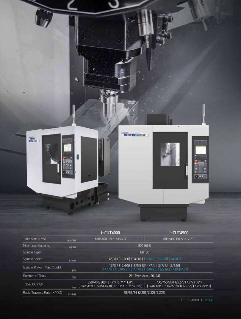
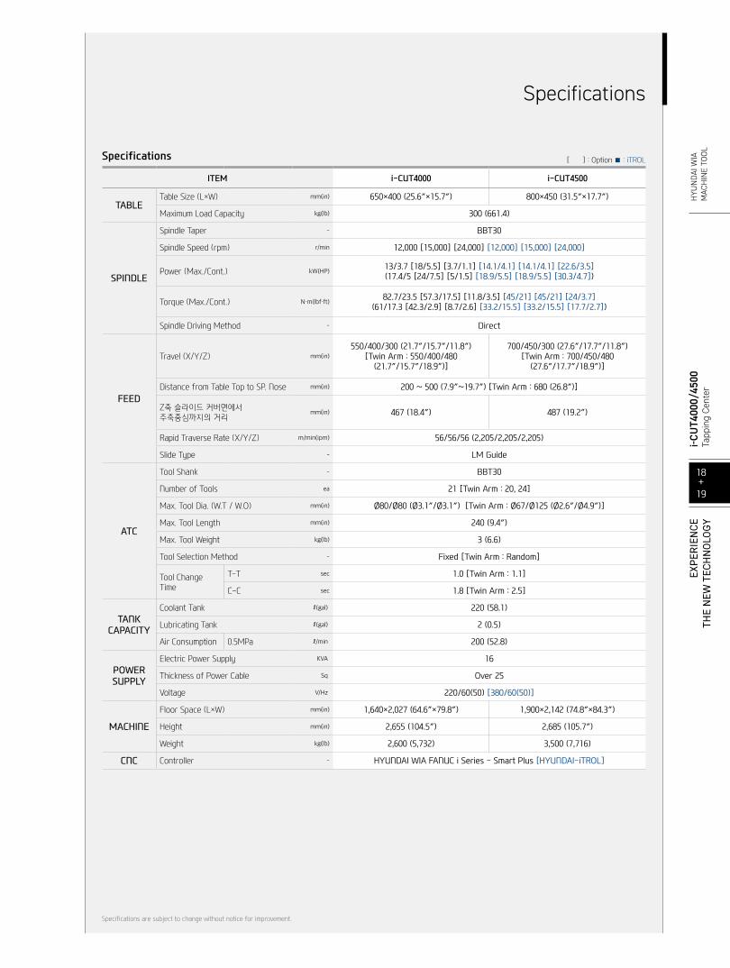
i-CUT4000 i-CUT4500Table Size (L×W) mm(in) 650×400 (25.6″×15.7″) 800×450 (31.5″×17.7″)
Max. Load Capacity kg(lb) 300 (661)
Spindle Taper - BBT30
Spindle Speed r/min 12,000 [15,000] [24,000] [12,000] [15,000] [24,000]
Spindle Power (Max./Cont.)kW
13/3.7 (17.4/5) [18/5.5 (24.1/7.4)] [3.7/1.1 (5/1.5)][14.1/4.1 (18.9/5.5)] [14.1/4.1 (18.9/5.5)] [22.6/3.5 (30.3/4.7)]
Number of Tools EA 21 [Twin Arm : 20, 24]
Travel (X/Y/Z)mm
550/400/300 (21.7″/15.7″/11.8″)[Twin Arm : 550/400/480 (21.7″/15.7″/18.9″)]
700/450/300 (29.5″/17.7″/11.8″)[Twin Arm : 700/450/480 (29.5″/17.7″/18.9″)]
Rapid Traverse Rate (X/Y/Z) m/min 56/56/56 (2,205/2,205/2,205)
[ ] : Option ■ : iTROL
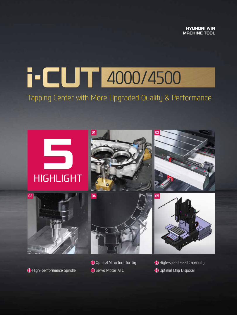
➊ ➊ Optimal Structure for Jig ➋➋ High-speed Feed Capability
➌➌ High-performance Spindle ➍➍ Servo Motor ATC ➎➎ Optimal Chip Disposal
4000/4500Tapping Center with More Upgraded Quality & Performance
HYUNDAI WIAMACHINE TOOL
01
04
02
03 05
5HIGHLIGHT
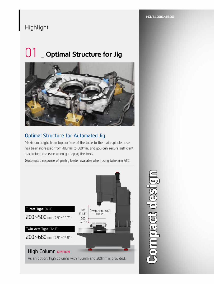
Optimal Structure for Automated JigMaximum height from top surface of the table to the main spindle nose has been increased from 480mm to 500mm, and you can secure sufficient machining area even when you apply the tools.
(Automated response of gantry loader available when using twin-arm ATC)
High Column As an option, high columns with 150mm and 300mm is provided.
Turret Type (A~B)
200~500 mm (7.9″~19.7″)
Twin Arm Type (A~B)
200~680 mm (7.9″~26.8″)
Highlight
01 _ Optimal Structure for Jig
Com
pact
des
ign
Com
pact
des
ign
300(11.8″)
[Twin Arm : 480](18.9″)
200(7.9″)
04+05
i-CUT4
000/
4500
Tapp
ing
Cent
erEX
PER
IEN
CETH
E N
EW T
ECH
NO
LOGY
H
YUN
DAI W
IAM
ACH
INE
TOOL
Highlight
02 _ High-speed Feed Capability
Rapid Traverse Rate (X/Y/Z)
56/56/56 m/min (2,205/2,205/2,205 ipm)
Travel (X/Y/Z) [ ] : Option
i-CUT4000
550/400/300 mm (21.7″/15.7″/11.8″)[Twin Arm : 550/400/480 (21.7″/15.7″/18.9″)]
i-CUT4500
700/450/300 mm (27.6″/17.7″/13″)[Twin Arm : 700/450/480 (27.6″/17.7″/18.9″)]
Ball ScrewLubricating ball screw support bearings with oil helps improve the durability of the bearing.
High-performance Double-seal Type LM GuideApplication of high-performance LM guide featuring double-seal attachment structure has significantly improved the durability of LM guide.56
/56/
56 m
in56
/56/
56 m
in
Highlight
03 _ High-performance Spindle
Direct SpindleIt has excellent power transmission capability from applying a direct-drive spindle which directly connects the motor and spindle, and it achieves a maximum rotation speed of 24,000r/min to allow for a wide range of machining.
Spindle Air Purge ApplicationThe main shaft motor cover prevents coolant from flowing into the head. In addition, by designing the spindle air purge through the spindle, the ability to remove chips from the spindle is improved.
Spindle Thru Coolant As an option, 20/30/70 bar through spindle coolant is available.
Dual Contact SpindleThe Big Plus spindle system provides dual contact between the spindle face and the flange face of the tool holder. Max
. 24,
000
rpm
Max
. 24,
000
rpm
06+07
i-CUT4
000/
4500
Tapp
ing
Cent
erEX
PER
IEN
CETH
E N
EW T
ECH
NO
LOGY
H
YUN
DAI W
IAM
ACH
INE
TOOL
Highlight
04 _ Servo Motor ATC
Servo ATCServo motor is applied on the ATC to reduce tool change time. Also, accurate tool positioning control increases cutting stability.
(Turret Type : Servo Motor / Twin Arm Type : Inverter Motor)
Best-in-class Tool Change Times
Turret Type MagazineUnlike the previous models that featured a 14-tool magazine, the i-CUT4000/4500 adopted a 21-tool magazine as standard to expand the tooling range.
Twin Arm Type For i-CUT4000/4500, twin-arm type ATC comes as option for gantry automation. (Turret type ATC : Gantry automation cannot be implemented due to interference with the magazine.)
0.3 sec reduction
2.1 sec
1.8 sec
Previous Model
i-CUT4000
C-C
C-C
Existing 14 tool → 21 tool increase
21 T
ool /
C-C
: 1.
8 se
c21
Too
l / C
-C :
1.8
sec
Highlight
05 _ Optimal Chip Disposal
Improvement of Chip Disposal CapabilityThe chip disposal capability has been significantly improved compared to the previous equipment with standard application of two shower coolants, bed coolants, improvement of chip disposal tilt angle of the bed, and improvement of flood coolant position.
ITEM i-CUT4000/4500 Previous Model
❶❶ Shower Coolant Standard Option
❷❷ Bed Flushing Coolant Standard : 2EA Non Applicable
❸❸ Flood Coolant
3 Locations on both sides of the equipment(Concentrated spraying on
workpiece possible)
4 Locations at the bot-tom of the spindle
(Concentrated spraying on workpiece possible)
❶❶
❷❷
❸❸
Chip Conveyor
HingeChip Type : Roughing Chip, Long Chip, Chip complex
Highly efficient when disposing a lot of chips. Capable of han-dling stringy chips.
ScraperChip Type : Finely broken chip blown out
Convenient for shortly cut chips.
❖ Drum FilterChip Type : Powder, Micro Chip
Advantageous in precision, as the chips do not flow in to the coolant nozzle.
08+09
i-CUT4
000/
4500
Tapp
ing
Cent
erEX
PER
IEN
CETH
E N
EW T
ECH
NO
LOGY
H
YUN
DAI W
IAM
ACH
INE
TOOL
Cutting Possibility
FACE MILL (Material : S45C (Carbon steel)〉
Tool dia. Ø63×5F
Spindle speed 3,000 r/min
Rapid feed rate 5,700 mm/min
Cutting width 50 mm
Cutting depth 4 mm
Chip quantity 1,140 cc/min
DRILL (Material : S45C (Carbon steel)〉
Tool dia. Ø43
Spindle speed 199 r/min
Rapid feed rate 39 mm/min
Cutting width 43 mm
Cutting depth 60 mm
Chip quantity 57 cc/min
TAP (Material : S45C (Carbon steel)〉
Tool dia. M27×P3.0
Spindle speed 320 r/min
Rapid feed rate 960 mm/min
Cutting width 36 mm
Chip quantity 54 mm
Cutting Possibility
❖ The above results might be different based on your processing circumstances.
1,14
0 cc
/min
1,14
0 cc
/min
Optimal Structure for Electric Car Battery Case machining
Convenience
NC Rotary Table & Hydraulic SupplyVarious shapes of products can be processed when using NC Rotary Table. In addition, 100 bar of high pressure hydraulic unit for the fixture increases the tightening power of the teeth.
MQL (Minimal Quantity Lubrication)
The goal of this system is to spray only the amount of lubricant required to prevent heat and chip build up at the cutting tool or work piece face.
Lubrication SystemBy applying lubricant only when the machines axis are moving lubrication consumption is reduced by compared to standard systems.
Oil SkimmerAn oil skimmer can increase coolant and tool life by removing tramp oil contaminants.
Touch SensorWorkpiece coordinate values can be set automatically using the optional spindle probe.
TLMTool lengths and diameters can be set automatically using the optional tool setter.This can also be used to monitor attrition and detect broken tools.
Mist CollectorMist Collector reduces the amount of smoke and oil mist in the air. This helps build a safe and comfortable working environment and improve durability.
Precision & Ecosystem
10+11
i-CUT4
000/
4500
Tapp
ing
Cent
erEX
PER
IEN
CETH
E N
EW T
ECH
NO
LOGY
H
YUN
DAI W
IAM
ACH
INE
TOOL
Automation System
Gantry Loader SystemGantry loader transfers raw material from in-stocker to machine automatically, starting machining process. Gantry automation provides good equipment access during operation and easy work monitoring, program modification and maintenance. In addition, small installation area facilitates optimized factory layout.
Robot SystemWith its know-how and experience, Hyundai WIA is globally recognized in the field of automation. Robot automation features flexible responsive-ness, convenience and maintenance regardless of type for automation construction.
Automation System
Dialogue Program (Smart Guide-i) This software offers maximum user convenience through a dialogue program from
setup to machining. This includes writing machining programs and simulation checks.
HYUNDAI WIA FANUC - SMART PLUS
FANUC 0i Plus Series● Customization functions are already included and offer an easy way to
create HMI screens that are tailored to the application.
● The advantage being that existing programs can be used immediately and that new programs can be developed without the need for costly redundancies.
● Providing the high-performance offered by FANUC servo technology, this CNC also offers the same user-friendly convenience over the complete range.
10.4″ Monitor as a Standard
Smart Machine ControlFast Cycle Time Technology
Fine Surface Technology
AI Contour Control AICC-2 (200 blocks)
Smooth Tolerance Control 0.1μm command and specify tolerance
JERK Control Diminished vibration by controllingacceleration speed
Machining ConditionSelection
Designated machining level based on speed & quality
Machining Quality Control Function Smooth Tolerance+ integrated support
Part Program Storage 5120M (2MB)
No. of Registerable Programs 1000 EA
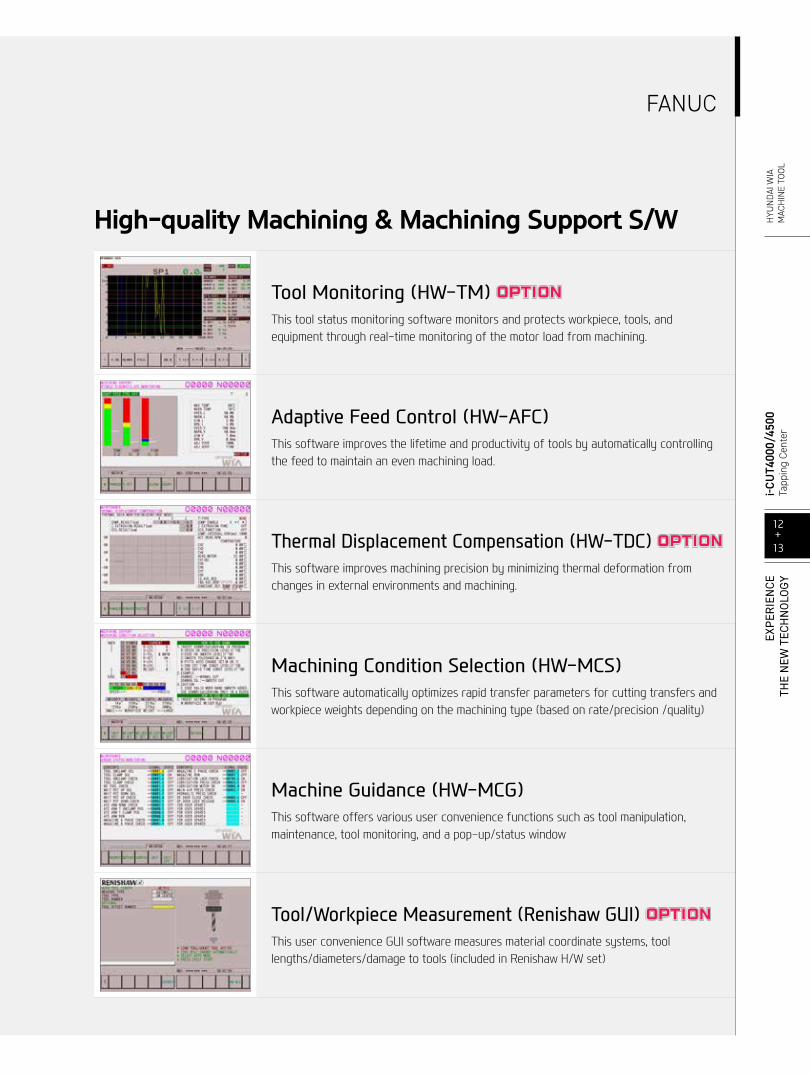
Tool Monitoring (HW-TM) This tool status monitoring software monitors and protects workpiece, tools, and equipment through real-time monitoring of the motor load from machining.
Adaptive Feed Control (HW-AFC)This software improves the lifetime and productivity of tools by automatically controlling the feed to maintain an even machining load.
Thermal Displacement Compensation (HW-TDC) This software improves machining precision by minimizing thermal deformation from changes in external environments and machining.
Machining Condition Selection (HW-MCS)This software automatically optimizes rapid transfer parameters for cutting transfers and workpiece weights depending on the machining type (based on rate/precision /quality)
Machine Guidance (HW-MCG)This software offers various user convenience functions such as tool manipulation, maintenance, tool monitoring, and a pop-up/status window
Tool/Workpiece Measurement (Renishaw GUI) This user convenience GUI software measures material coordinate systems, toollengths/diameters/damage to tools (included in Renishaw H/W set)
High-quality Machining & Machining Support S/W
12+13
i-CUT4
000/
4500
Tapp
ing
Cent
erEX
PER
IEN
CETH
E N
EW T
ECH
NO
LOGY
H
YUN
DAI W
IAM
ACH
INE
TOOL
FANUC
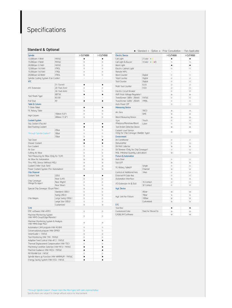
Specifications
Spindle i-CUT4000 i-CUT450012,000rpm (13kW) FANUC ● ●15,000rpm (15kW) FANUC ○ ○24,000rpm (3.7kW) FANUC ○ ○12,000rpm (14.1kW) iTROL ○ ○15,000rpm (14.1kW) iTROL ○ ○24,000rpm (22.6kW) iTROL ○ ○Spindle Cooling System (Fan Cooller) - -ATC
ATC Extension21 (Turret) ● ●20 (Twin Arm) ○ ○24 (Twin Arm) ○ ○
Tool Shank TypeBBT30 ● ●BCV30 - -
Pull Stud 45° ● ●Table & ColumnT-Slote Pallet ● ●NC Rotary Table ☆ ☆
High Column150mm (5.9″) ○ ○300mm (11.8″) ○ ○
Coolant SystemStd. Coolant (Nozzle) ● ●Bed Flushing Coolant ● ●
Through Spindle Coolant*20bar ○ ○30bar ○ ○70bar ○ ○
Top Cover ● ●Shower Coolant ● ●Gun Coolant ○ ○Air Gun ○ ○Cutting Air Blow ○ ○Tool Measuring Air Blow (Only for TLM) ○ ○Air Blow for Automation ☆ ☆Thru MQL Device (Without MQL) ☆ ☆Coolant Chiller (Sub Tank) ☆ ☆Power Coolant System (For Automation) ☆ ☆Chip DisposalCoolant Tank 220ℓ ● ●
Chip Conveyor(Hinge/Scraper)
Rear (Left) ○ ○Rear (Right) ○ ○Rear (Rear) ○ ○
Special Chip Conveyor (Drum Filter) ☆ ☆
Chip Wagon
Standard (180ℓ) ○ ○Swing (200ℓ) ○ ○Large Swing (290ℓ) ○ ○Large Size (330ℓ) ○ ○Customized ☆ ☆
S/WDNC software (HW-eDNC) ○ ○
Machine Monitoring System(HW-MMS Cloud/Edge/Remote) ○ ○
Machine Monitoring System & Analysis(HW-MMS Edge Plus) ☆ ☆
Automation CAM program (HW-ACAM) ○ ○Conversational program (HW-DPRO) ○ ○SmartGuide-i : FANUC ○ ○Tool Monitoring (HW-TM) : FANUC ○ ○Adaptive Feed Control (HW-AFC) : FANUC ● ●Thermal Displacement Compensation (HW-TDC) ○ ○Machining Condition Selection (HW-MCS) : FANUC ● ●Machine Guidance (HW-MCG) : FANUC ● ●RENISHAW GUI : FANUC ○ ○Spindle Warm up Function (HW-WARMUP) : FANUC ● ●Energy Saving System (HW-ESS) : FANUC ● ●
Electric Device i-CUT4000 i-CUT4500Call Light 2 Color : ■■ ● ●Call Light & Buzzer 3 Color : ■■■B ○ ○Work Light ● ●Electric Cabinet Light ○ ○Remote MPG - -Work Counter Digital ○ ○Total Counter Digital ○ ○Tool Counter Digital ○ ○
Multi Tool Counter6 EA ○ ○9 EA ○ ○
Electric Circuit Breaker ○ ○AVR (Auto Voltage Regulator) ☆ ☆Transformer (380V : 20kVA) FANUC ○ ○Transformer (220V : 25kVA) iTROL ○ ○Auto Power Off ○ ○Measuring Device
Air ZeroTACO ☆ ☆SMC ☆ ☆
Work Measuring Device ☆ ☆
TLM(Marposs/Renishaw/Blum)
Touch ○ ○Laser ○ ○
Tool Broken Detective Device ☆ ☆
Coolant Level Sensor (Only for Chip Conveyor, Bladder Type) ☆ ☆
EnviornmentAir Conditioner ○ ○Dehumidifier ○ ○Oil Mist Collector ☆ ☆Oil Skimmer (Only for Chip Conveyor) ○ ○MQL (Minimal Quantity Lubrication) ☆ ☆Fixture & AutomationAuto Door ○ ○Sub O/P ☆ ☆
NC Rotary TableI/FSingle ○ ○Channel ☆ ☆
Control of Additional Axis 1Axis ○ ○External M Code 4ea ○ ○Automation Interface ☆ ☆
I/O Extension (In & Out)16 Contact ○ ○32 Contact ○ ○
Hyd. Device
Hyd. Unit for Fixture
45bar ☆ ☆70bar ☆ ☆100bar ☆ ☆Customized ☆ ☆
ETCTool Box ● ●Customized Color Need for Munsel No. ☆ ☆CAD&CAM Software ☆ ☆
Standard & Optional ● : Standard ○ : Option ☆ : Prior Consultation - : Non Applicable
*Through Spindle Coolant : Please check the filter types with sales representative.Specifications are subject to change without notice for improvement.
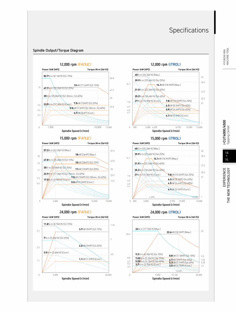
Spindle Output/Torque Diagram
Power (kW [HP]) Torque (N·m [lbf·ft])
Spindle Speed (r/min)
14.1
4.1
7.8
6.2
4.9
0 3,000500 4,290 8,790 10,090 12,000
45
21
39.9
31.5
25.2
1
45N·m [33.2lbf·ft] (Max.)
14.1kW [18.9HP] (Max.)
7.8kW [10.5HP] (S6 25%)
6.2kW [8.3HP] (S6 40%)
4.9kW [6.6HP] (S6 60%)
4.1kW [5.5HP] (Cont.)
21N·m [15.5lbf·ft] (Cont.)
25.2N·m [18.6lbf·ft] (S6 60%)
31.5N·m [23.2lbf·ft] (S6 40%)
39.9N·m [29.4lbf·ft] (S6 25%)
Power (kW [HP]) Torque (N·m [lbf·ft])
Spindle Speed (r/min)
22.6
9,000 15,120
16,600
24,000
24
9.3
7.035.553.73.5
5.36.7
8.8
22.6kW [30.3HP] (Max.)
0
24N·m [17.7lbf·ft] (Max.)
9.3N·m [6.9lbf·ft] (S6 10%) 8.8kW [11.8HP] (S6 10%)
6.7kW [9HP] (S6 25%)5.3kW [7.1HP] (S6 40%)3.5kW [4.7HP] (Cont.)
7.03N·m [5.2lbf·ft] (S6 25%)5.55N·m [4.1lbf·ft] (S6 40%)3.7N·m [2.7lbf·ft] (Cont.)
14.1
4.1
7.8
6.2
4.9
0
4,290
8,790 10,090
45
21
39.9
31.5
25.2
Power (kW [HP]) Torque (N·m [lbf·ft])
Spindle Speed (r/min)3,000500 15,000
1
45N·m [33.2lbf·ft] (Max.)
14.1kW [18.9HP] (Max.)
14,650
7.8kW [10.5HP] (S6 25%)
6.2kW [8.3HP] (S6 40%)
4.9kW [6.6HP] (S6 60%)
4.1kW [5.5HP] (Cont.)
21N·m [15.5lbf·ft] (Cont.)
25.2N·m [18.6lbf·ft] (S6 60%)
31.5N·m [23.2lbf·ft] (S6 40%)
39.9N·m [29.4lbf·ft] (S6 25%)
Power (kW [HP]) Torque (N·m [lbf·ft])
Spindle Speed (r/min)
3.7
2.2
1.1
3,000 24,000
11.8
7
3.5
0
18
15
7.5
11
5.5
0 12,000
57.3
17.5
47.8
35
23.9
Power (kW [HP]) Torque (N·m [lbf·ft])
Spindle Speed (r/min)3,000 15,000
Power (kW [HP]) Torque (N·m [lbf·ft])
Spindle Speed (r/min)0
13
7.5
5.5
3.7
1,500 10,000 12,000
82.8
35
47.7
23.5
13kW [17.4HP] (S3 15%)
7.5kW [10HP] (S3 25%)
5.5kW [7.5HP] (S2 30min, S3 60%)
3.7kW [5HP] (Cont.)
82.7N·m [61 lbf·ft] (S3 15%)
47.7N·m [35.2lbf·ft] (S3 25%)
35N·m [25.8lbf·ft] (S2 30min, S3 60%)
23.5N·m [17.3lbf·ft] (Cont.)
47.8N·m [35.3lbf·ft] (S3 15%)
57.3N·m [42.3lbf·ft] (Max.)
35N·m [25.8lbf·ft] (S3 25%)
23.9N·m [17.6lbf·ft] (S2 30min, S3 60%)
17.5N·m [2.9lbf·ft] (Cont.)
18kW [24HP] (Max.)
15kW [20HP] (S3 15%)
11kW [15HP] (S3 25%)
7.5kW [10HP] (S2 30min, S3 60%)
5.5kW [7.5HP] (Cont.)
11.8N·m [8.7lbf·ft] (S3 15%)
7N·m [5.2lbf·ft] (S3 25%)
3.5N·m [2.6lbf·ft] (Cont.)
3.7kW [5HP] (S3 15%)
2.2kW [3HP] (S3 25%)
1.1kW [1.5HP] (Cont.)
12,000 rpm (FANUC)
15,000 rpm (FANUC)
24,000 rpm (FANUC)
12,000 rpm (iTROL)
15,000 rpm (iTROL)
24,000 rpm (iTROL)
Specifications
14+15
i-CUT4
000/
4500
Tapp
ing
Cent
erEX
PER
IEN
CETH
E N
EW T
ECH
NO
LOGY
H
YUN
DAI W
IAM
ACH
INE
TOOL
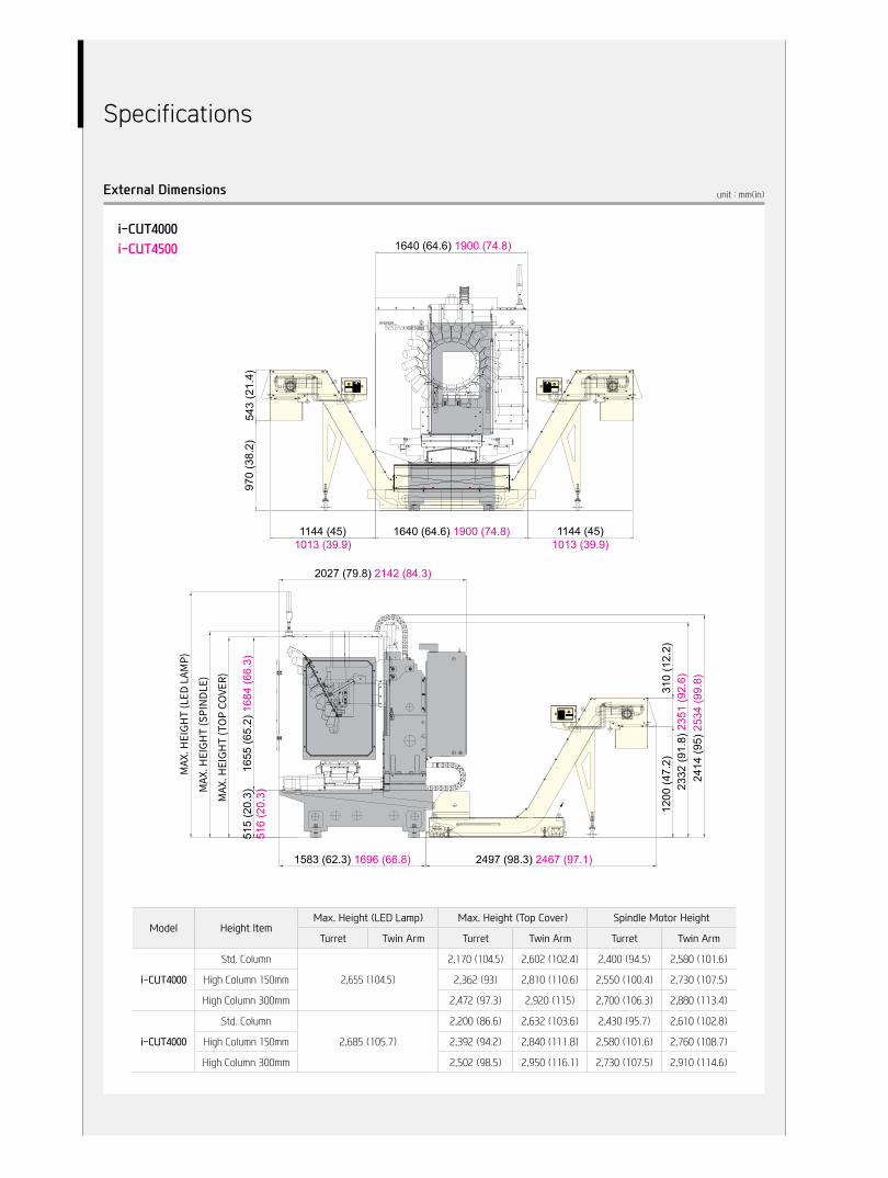
1640 (64.6) 1900 (74.8)
1144 (45)1013 (39.9)
970
(38.
2)54
3 (2
1.4)
1640 (64.6) 1900 (74.8) 1144 (45)1013 (39.9)
515
(20.
3)51
6 (2
0.3)
1655
(65.
2) 1
684
(66.
3)
1583 (62.3) 1696 (66.8)
1200
(47.
2)31
0 (1
2.2)
2027 (79.8) 2142 (84.3)
2497 (98.3) 2467 (97.1)
2332
(91.
8) 2
351
(92.
6)24
14 (9
5) 2
534
(99.
8)
Model Height ItemMax. Height (LED Lamp) Max. Height (Top Cover) Spindle Motor Height
Turret Twin Arm Turret Twin Arm Turret Twin Arm
i-CUT4000
Std. Column
2,655 (104.5)
2,170 (104.5) 2,602 (102.4) 2,400 (94.5) 2,580 (101.6)
High Column 150mm 2,362 (93) 2,810 (110.6) 2,550 (100.4) 2,730 (107.5)
High Column 300mm 2,472 (97.3) 2,920 (115) 2,700 (106.3) 2,880 (113.4)
i-CUT4000
Std. Column
2,685 (105.7)
2,200 (86.6) 2,632 (103.6) 2,430 (95.7) 2,610 (102.8)
High Column 150mm 2,392 (94.2) 2,840 (111.8) 2,580 (101.6) 2,760 (108.7)
High Column 300mm 2,502 (98.5) 2,950 (116.1) 2,730 (107.5) 2,910 (114.6)
unit : mm(in)External Dimensions
i-CUT4000i-CUT4500
Specifications
16.4(0.64″)
19.7(0.77″)
Ø46
.05(
Ø1.
8″)
30°7/24
15.92(0.6″)
Ø32
(Ø1.
2″)
Ø39
.25(
Ø1.
5″)
60°3.18(0.12″)
15.9(0.6″)
R0.75
M12x1.75
43.55(1.7″)25(1″)
47.8(1.9″)
Ø14
.5(Ø
0.57
″)
Ø31
.75
(Ø1.
25″)
Ø12
.4(Ø
0.5″
)
19.1(0.7″)
±15'
4.25(0.16″)35(1.4″)
16.1
(0.6
3″)
4.75(0.18″)
2.75(0.1″)35°
8.15(0.32″)
1.25(0.04″)
1.8(0.07″)
29(1.14″)
Ø4.15(Ø0.16″)
13(0.5″)2.5x45°
R2.15
Ø13
.35
(Ø0.
52″)
Ø16
.5(Ø
0.65
″)
M12x1.75
Ø9.
3(Ø
0.36
″)
30° ±1
45° ±15'
17(0.6″)
16.3(0.6″)
16.1
(0.6
″)
16.3(0.6″)
24(0.9″)
70.4(2.7″)48.4(1.9″)±0.2
13.6(0.5″)±0.120
(0.8″)2±0.4(0.08″)
7(0.3″)
Ø12
.5(Ø
0.5″
)(Ø
14)
([Ø0.
5″])
Ø17
(Ø0.
6″)
Ø9.
5(Ø
0.4″
)
Ø12
.5(Ø
0.5″
)
Ø7
(Ø0.
3″)
Ø13(Ø0.5″)
2.5(0.1″)
2.5(0.1″)
5(0.2″)
20(0.8″) 23(0.9″)
43(1.7″)
4(0.15″)
3(0.11″)
13(0.5″)
Ø11
(Ø0.
4″)
(Ø2.
5)([Ø
0.01
″])
Ø46
(Ø1.
8″)
Ø38
(Ø1.
5″)
Ø31
.75
(Ø1.
25″)
(Ø17
.6)
([Ø0.
7″])
8(0.3″)
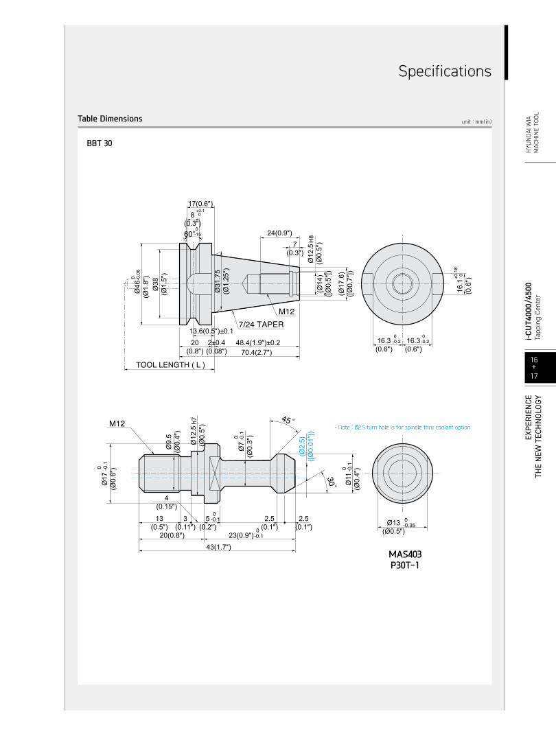
MAS403P30T-1
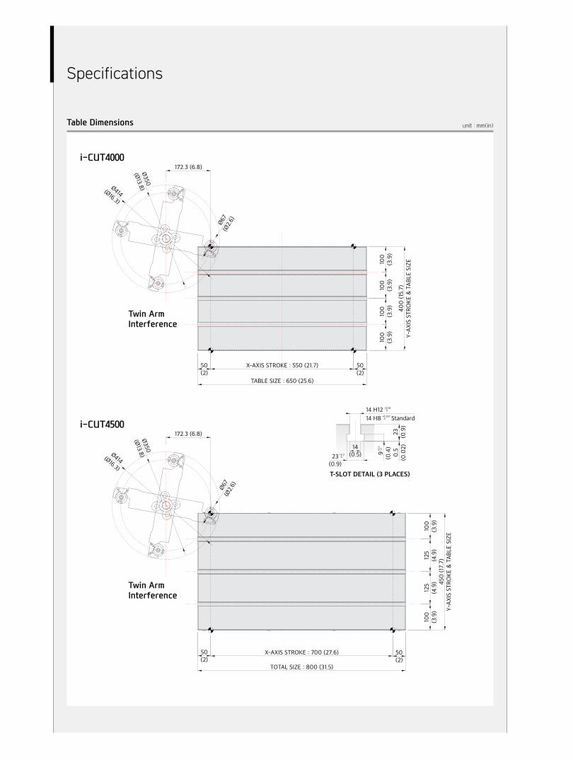
unit : mm(in)Table Dimensions
16+17
i-CUT4
000/
4500
Tapp
ing
Cent
erEX
PER
IEN
CETH
E N
EW T
ECH
NO
LOGY
H
YUN
DAI W
IAM
ACH
INE
TOOL
Specifications
BBT 30
•Note : Ø2.5 turn hole is for spindle thru coolant option
unit : mm(in)Table Dimensions
T-SLOT DETAIL (3 PLACES)
14 H1214 H8
+0.180
+0.0270
+0.20
+0.20
9(0.4)
0.5
(0.02)
23 (0.9)
14(0.5)23
(0.9)
Ø67
(Ø2.6)
172.3 (6.8)Ø350
(Ø13.8)Ø414(Ø16.3)
Ø67
(Ø2.6)
172.3 (6.8)Ø350
(Ø13.8)Ø414(Ø16.3)
50(2)
X-AXIS STROKE : 550 (21.7) 50(2)
100
(3.9)
100
(3.9)
100
(3.9)
100
(3.9)
400 (15.7)
Y-AXIS STROKE & TABLE SIZE
TABLE SIZE : 650 (25.6)
450 (17.7)
Y-AXIS STROKE & TABLE SIZE
100
(3.9)
125
(4.9)
125
(4.9)
100
(3.9)
50(2)
TOTAL SIZE : 800 (31.5)
X-AXIS STROKE : 700 (27.6) 50(2)
Standard
i-CUT4000
i-CUT4500
Twin Arm Interference
Twin Arm Interference
Specifications
Specifications are subject to change without notice for improvement.
Specifications [ ] : Option ◼︎ : iTROL
18+19
i-CUT4
000/
4500
Tapp
ing
Cent
erEX
PER
IEN
CETH
E N
EW T
ECH
NO
LOGY
H
YUN
DAI W
IAM
ACH
INE
TOOL
Specifications
ITEM i-CUT4000 i-CUT4500
TABLETable Size (L×W) mm(in) 650×400 (25.6″×15.7″) 800×450 (31.5″×17.7″)
Maximum Load Capacity kg(lb) 300 (661.4)
SPINDLE
Spindle Taper - BBT30
Spindle Speed (rpm) r/min 12,000 [15,000] [24,000] [12,000] [15,000] [24,000]
Power (Max./Cont.) kW(HP)13/3.7 [18/5.5] [3.7/1.1] [14.1/4.1] [14.1/4.1] [22.6/3.5](17.4/5 [24/7.5] [5/1.5] [18.9/5.5] [18.9/5.5] [30.3/4.7])
Torque (Max./Cont.) N・m(lbf・ft)82.7/23.5 [57.3/17.5] [11.8/3.5] [45/21] [45/21] [24/3.7]
(61/17.3 [42.3/2.9] [8.7/2.6] [33.2/15.5] [33.2/15.5] [17.7/2.7])
Spindle Driving Method - Direct
FEED
Travel (X/Y/Z) mm(in)550/400/300 (21.7″/15.7″/11.8″)
[Twin Arm : 550/400/480 (21.7″/15.7″/18.9″)]
700/450/300 (27.6″/17.7″/11.8″)[Twin Arm : 700/450/480
(27.6″/17.7″/18.9″)]
Distance from Table Top to SP. Nose mm(in) 200 ~ 500 (7.9″~19.7″) [Twin Arm : 680 (26.8″)]
Z축 슬라이드 커버면에서 주축중심까지의 거리
mm(in) 467 (18.4″) 487 (19.2″)
Rapid Traverse Rate (X/Y/Z) m/min(ipm) 56/56/56 (2,205/2,205/2,205)
Slide Type - LM Guide
ATC
Tool Shank - BBT30
Number of Tools ea 21 [Twin Arm : 20, 24]
Max. Tool Dia. (W.T / W.O) mm(in) Ø80/Ø80 (Ø3.1″/Ø3.1″) [Twin Arm : Ø67/Ø125 (Ø2.6″/Ø4.9″)]
Max. Tool Length mm(in) 240 (9.4″)
Max. Tool Weight kg(lb) 3 (6.6)
Tool Selection Method - Fixed [Twin Arm : Random]
Tool Change Time
T-T sec 1.0 [Twin Arm : 1.1]
C-C sec 1.8 [Twin Arm : 2.5]
TANKCAPACITY
Coolant Tank ℓ(gal) 220 (58.1)
Lubricating Tank ℓ(gal) 2 (0.5)
Air Consumption 0.5MPa ℓ/min 200 (52.8)
POWERSUPPLY
Electric Power Supply KVA 16
Thickness of Power Cable Sq Over 25
Voltage V/Hz 220/60(50) [380/60(50)]
MACHINE
Floor Space (L×W) mm(in) 1,640×2,027 (64.6″×79.8″) 1,900×2,142 (74.8″×84.3″)
Height mm(in) 2,655 (104.5″) 2,685 (105.7″)
Weight kg(lb) 2,600 (5,732) 3,500 (7,716)
CNC Controller - HYUNDAI WIA FANUC i Series - Smart Plus [HYUNDAI-iTROL]
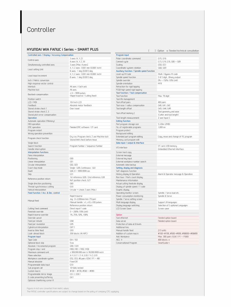
HYUNDAI WIA FANUC i Series - SMART PLUS
Figures in inch are converted from metric values.The FANUC controller specifications are subject to change based on the policy of company CNC supplying.
Controlled axis / Display / Accuracy Compensation
Control axes3 axes (X, Y, Z)4 axes (X, Y, Z, B)
Simultaneously controlled axes 3 axes [Max. 4 axes]
Least setting UnitX, Y, Z axes : 0.001 mm (0.0001 inch)B axes : 1 deg [0.001] deg
Least input incrementX, Y, Z axes : 0.001 mm (0.0001 inch)B axes : 1 deg [0.001] deg
Inch / Metric conversionHigh response vector controlInterlock All axes / Each axisMachine lock All axes
Backlash compensation ± 0 ~ 9999 pulses(Rapid traverse / Cutting feed)
Position switchLCD / MDI 10.4 inch LCDFeedback Absolute motor feedback Stored stroke check 1 Over travel Stored stroke check 2, 3Stored pitch error compensationOperationAutomatic operation (Memory)MDI operationDNC operation Needed DNC software / CF cardProgram restartWrong operation prevention
Program check functionDry run, Program check, Z axe Machine lockStored limit check before move
Single blockSearch function Program Number / Sequence NumberHandle interruptionInterpolation functionsNano interpolationPositioning G00 Linear interpolation G01 Circular interpolation G02, G03 Exact stop mode Single : G09, Continuous : G61Dwell G04, 0 ~ 9999.9999 sec Skip G31
Reference position return1st reference, G28 / 2nd reference, G30Ref. position check, G27
Single direction positioning G60 Thread synchronous cutting G33 Helical interpolation Circular + Linear 2 axes (Max.) Feed function / Acc. & Dec. control
Manual feed
Rapid traverseJog : 0~2,000mm/min (79 ipm)Manual handle : x1, x10, x100 pulsesReference position return
Cutting Feed command Direct input F codeFeedrate override 0 ~ 200% (10% Unit)Rapid traverse override 1%, 25%, 50%, 100%Override cancelFeed per minute G94 Feed per revolution G95 Cylindrical interpolation G07.1 Inverse time feed G93 Look-ahead block 200 blocks (AI APC) Program inputTape Code EIA / ISO Optional block skip 9 ea Absolute / Incremental program G90 / G91 Program stop / end M00, M01 / M02, M30 Maximum command unit ± 999,999.999 mm (± 99,999.9999 inch)Plane selection X-Y, G17 / Z-X, G18 / Y-Z, G19Workpiece coordinate system G52, G53, 48 pairs (G54.1 P1 ~ 48) Manual absolute Fixed ONProgrammable data input G10 Sub program call 10 folds nestedCustom macro #100 ~ #199, #500 ~ #999Programmable mirror image G51.1, G50.1 G code preventing buffering G4.1 Optional chamfering corner R
[ ] : Option ☆ Needed technical consultation
Program inputPolar coordinate command G15, G16 Canned cycle G73, G74, G76, G80 ~ G89Scaling G50, G51 Coordinate system rotation G68, G69 Auxiliary function / Spindle speed functionLevel-up M Code Multi / Bypass M codeSpindle speed function S & 5 digit , Binary outputSpindle override 0% ~ 150% (10% Unit) Spindle orientation M19Retraction for rigid tapping FSSB high speed rigid tappingTool function / Tool compensationTool function Max. T8 digit Tool life managementTool offset pairs 400 pairs Tool nose / radius compensation G40, G41, G42 Tool length offset G43, G44, G49
Tool offset memory CTool geometry and wear(Cutter and tool length)
Tool length measurement Z axe Input C Editing functionPart program storage size 5,120m (2MB)No. of registerable programs 1,000 eaProgram protectBackground editingExtended part program editing Copy, move and change of NC programMemory card program editData input / output & Interface
I/O interfaceCF card, USB memoryEmbedded Ethernet interface
Screen hard copyExternal messageExternal key inputExternal workpiece number searchAutomatic data backupSetting, display and diagnosisSelf-diagnosis functionHistory display & Operation Alarm & Operator message & OperationRun hour / Parts count displayMaintenance informationActual cutting feedrate displayDisplay of spindle speed / T codeGraphic displayOperating monitor screen Spindle / Servo load etc.Power consumption monitoring Spindle & ServoSpindle / Servo setting screenMulti language display Support 24 languagesDisplay language switching Selection of 5 optional LanguagesLCD Screen Saver Screen saver
OptionFast ethernet Needed option boardData server Needed option boardProtection of data at 8 levelsAdditional AxisManual handle feed 2/3 units Addition of custom macro #100~#199, #500~#999, #98000~#98499Add. Workpiece Max. 300 pairs (G54.1 P1 ~ P300)AICC Ⅱ 400 blocks ☆ Conversational Program SmartGuide-i
Controller
HYUNDAI-iTROL (SIEMENS 828D)
Figures in inch are converted from metric values. | Specifications are subject to change without notice for improvement.
Auxiliary function / Spindle speed functionAuxiliary function M Code 4 digitSpindle speed function S Code 5 digitSpindle override 0% ~ 150% (10% Unit)Spindle orientation SPOSRigid tappingAutometic mode Interchange Spindle / Axis modeConstant surface speed control G96, G97Spindle speed limitation LIMSTool function / Tool compensation
Tool functionTool number & Tool nameTool : T + Offset : D
Tool life management
Tools in tool list256 ea768 ea : (SW28X Mold)
Cutting Edges in tool list512 ea1,536 ea : (SW28X Mold)
Tool radius compensation ISO (G40, G41, G42)Tool length offsetGeometry / Wear compensationMeasurement of tool lengthTool management functionEditing function
Part program storage size5MB10MB : (SW28X Mold)
No. of registerable programs 750 eaExternal Strorage devices Local network, Server, USB, Flash driveBackground editingExtended part program editing Copy, move and change of NC programMemory card program edit Data input / output & Interface
I/O interfaceCF card interface (ONLY 10.4”) USB memory interfaceEmbedded Ethernet memory interface
ScreenshotSetting, display and diagnosisSelf-diagnosis function History display & Operation Alarm & Operator message & OperationRun hour / Parts count displayMaintenance informationActual cutting feedrate displayDisplay of spindle speed / T codeGraphic displayOperating monitor screen Spindle / Servo load etc.
Multi language display
Support 9 languages Chinese (Simplified/Traditional), English, French, German, Italian, Korean, Portuguese, Spanish
[☆ 22 Support languages : Inquiry need]LCD Screen Saver Screen saver & Motion sensing
OptionAdditional optional block skip 10 eaAdditional axis controlContour handwheel3D simulationReal time simulationShopMill Machining step programming for milling
Controlled axis / Display / Accuracy Compensation
Control axes3 axes (X, Y, Z)[4 axes (X, Y, Z, A)][5 axes (X, Y, Z, A, C)]
Simultaneously controlled axes Max. 4 axes
Least setting UnitX, Y, Z axes : 0.001 mm (0.0001 inch)[A, C (B) axes : 1 deg [0.001] deg]
Least input incrementX, Y, Z축 : 0.001 mm (0.0001 inch)[A, C (B) axes : 1 deg [0.001] deg]
Inch / Metric changeover G70 (inch) / G71 (metric)Interlock All axes / Each axisPitch error compensation Feedforward control
LCD / MDI10.4 inch color LCD[15 inch color LCD (With Touch panel)]
Keyboard QWERTY full keyboardStored stroke check Over travelOperationAutomatic operationMDI operationProgram restartProgram check function Dry run / Program check / Machine lockSingle blockBlock search Block searchRepositionWorking area limit Working area limitationsInterpolation functionsPositioning G00Linear interpolation G01
Circular interpolationCircular Interpolation CW (G02)Circular Interpolation CCW (G03)
Exact position stopSingle block exact stop (G09)Exact stop G60 (G601, G602, G603)
Dwell Dwell (G04)
Reference position returnReturn to reference pointReturn to 2nd reference point
Helical interpolationSpline interpolation Non-uniform rational B splines
Compressor for 3-axis machining(Improving machining quality) Compcad /Compcurv (Cycle 832)
Feed function / Acc. & Dec. control
Manual feed
Rapid traverseJogManual handleReference position return
Cutting Feed command Direct input F codeFeedrate override 0 ~ 200% (10% Unit)Rapid traverse override 1%, 25%, 50%, 100%Feed per minute G94Feed per revolution G95
Look-ahead block300 block450 block : (SW28X Mold)[600 block]
Program input
ISO correspondenceG291(ISO)/G290 (SIEMENS)(ISO G Code system-A)
Optional block skip 2Program stop / end M00, M01 / M02, M30Maximum command unit ± 999,999.999 mm, ± 99,999.9999 inchPlane selection X-Y : G17, X-Z : G18, Y-Z : G19
Workpiece coordinate system
G54 ~ G57, G505~G549G500 (Basic frame - setable zero offset)G53 (Work offset non modal)G153 (basic frame non modal)
Sub program call 11 folds nestedG code preventing buffering STOPREDrilling/Milling cycle Programing (Cycle 82, 83, 84, 840)User cycle
[ ] : Option ☆ Needed technical consultation
20+21
i-CUT4
000/
4500
Tapp
ing
Cent
erEX
PER
IEN
CETH
E N
EW T
ECH
NO
LOGY
H
YUN
DAI W
IAM
ACH
INE
TOOL
Controller
2021-07 001.002 KOR
With its top-quality HYUNDAI WIA machine tool creates a new and better world.
HEADQUARTERChangwon Technical Center/R&D Center/Factory 153, Jeongdong-ro, Seongsan-gu, Changwon-si, Gyeongsangnam-do, Korea TEL : +82 55 280 9114 FAX : +82 55 282 9114
Overseas Sales Team /R&D Center 37, Cheoldobangmulgwan-ro, Uiwang-si, Gyeonggi-do, Korea TEL : +82 31 8090 2539
OVERSEAS OFFICESHYUNDAI WIA Machine America corp. 450 Commerce Blvd, Carlstadt, NJ 07072, USA TEL : +1-201-987-7298
HYUNDAI WIA Europe GmbH Alexander-Fleming-Ring 57, 65428 Rüsselsheim Germany TEL : +49-0-6142-9256-0
HYUNDAI WIA Machine Tools China 2-3F, Bldg6, No.1535 Hongmei Road, Xuhui District, Shanghai, China TEL : +86-21-6427-9885
India Branch Office #4/169, 1st Floor, LOTTE BLDG, Rajiv Gandhi Salai, (OMR), Kandanchavadi, Chennai - 600096, Tamilnadu, India TEL : +91-76-0490-3348
Vietnam Branch Office Flat number 05, Service and Trade Center of Viet Huong Industrial Zone, Highway 13, Thuan Giao , Thuan An, Binh Duong, Vietnam TEL : +84-3-5399-5099
HYUNDAI WIA MT
www.youtube.com/HYUNDAIWIAMT