hypervelocity impact on rock - semantic scholar · 2015-07-28 · 1 chapter 32 hypervelocity impact...
TRANSCRIPT
1
Chapter 32
HYPERVELOCITY IMPACT ON ROCKby G. B. Clark, C. J. Haas, J.W Brown, and D. A. Summers
ABSTRACT
Concerted research efforts are being made to find new means of rock disintegration for more
rapid, efficient excavation. Water jets, metallic jets and hypervelocity projectiles have been found
to cut or break rock with varying degrees of efficiency depending upon several parameters, which
are being defined by research in Russia, Britain and the United States. Optimum performance of
high velocity impact agents is an important engineering factor. A concise review of research data is
presented together with a correlation and analysis of current theory and experimental results.
G. B. Clark is Director, and C. J. Haas, J.W. Brown, and D. A. Summers are Research Associates, Rock Mechanics
and Explosives Research Center; University of Missouri-Rolla;
2INTRODUCTION
While significant advances have been made in excavation of rock, largely in improvements
in drilling, blasting, loading and haulage, conventional operations have been improved until little
feasible increase in efficiency or rate of advance appears possible. Tunnel boring machines have
been developed which will excavate at rapid rates in soft to medium hard rock. Hypervelocity
impact is being intensively investigated as possible means of cutting and breaking rock, as well as
lasers, electric current, explosive drilling, high frequency vibration, etc. The current development
and use of high velocity small diameter water jets, metallic jets and projectiles of various materials
involve ultrahigh pressure phenomena of fundamental interest.
Rock disintegration by water jets has been investigated in the USSR for over a decade.
Large diameter jets of low velocity are used to mine coal, and high velocity capillary jets will cut
and break rocks under laboratory conditions. Velocity ranges for breaking and cutting are
dependent upon rock and jet properties, and pulsed jets break some rocks more easily than
continuous jets. Spectacular laboratory results have been reported for breakage of unconfined
blocks of some types of rocks. Compressors, pressure multipliers, gas explosion chambers and
water cannons have been used to generate jets. Jet properties, such as continuity, unit pressure,
total pressure, and stability have been measured. Results agree with theory, although the latter has
been established only for relatively low velocity flow. Diameter, speed of traversing and frequency
of pulsed jets affect rock response. Investigations in Britain have only recently begun
consideration of harder rocks and higher velocities, although water jet cores have been found to be
more continuous at lower velocities than previously believed. Lower limits of: jet velocity for rock
cutting were established for the rocks investigated.
Shaped charge jets employing liners have proved very effective for armor penetration, and
have found industrial application in tapping iron furnaces and perforating oil well casings.
Cursory attempts to use them for mining or excavating rock in the late 1940's were discouraging,
largely because of high costs. Only two basic studies of rock penetration have been reported since.
Hypervelocity projectile impact was studied mainly because of the interest in the impact of
meteorites upon space vehicles and upon rocks on the moon. The phenomena of particle impact on
rock and metal are similar in some respects, most metals tend to flow, and craters in rock are
larger because of the brittleness and low tensile strength of rock. Projectiles are usually accelerated
by means of light gas guns, although other means are employed.
3EQUATIONS OF STATE
Hypervelocity impact studies involve pressures, from one atmosphere to those in the
megabar range for gases, liquids and solids. Hence, it is desirable to be able to define equations of
state for the substances involved throughout the pertinent ranges of temperature and pressure.
Most high pressure data for water and minerals are for static conditions, although shock
parameters are tabulated for both. Several equations of state have been proposed for gases,
including the virial equation, KWB equation and a modified Abel equation, all for application to
gaseous products of the detonation of high (chemical) explosives.
Shock waves may be either non-reactive or reactive (a detonation) . The physical-
mathematical treatment is identical for both types except for the energy equation, and is restricted
largely to plane waves in most analyses. For weak shocks in gases the ideal equation of state is
usually employed. For detonations an equation of state should take into account the imperfections
of gases at high temperatures and pressures.
Equations of state for shock conditions in solids may take various forms. Empirical data
used for establishing Hugoniot curves for various materials is obtained (Ref. 1) from velocity
measurements. In early research shock and particle velocities were measured simultaneously and
the hydrodynamic conservation equations employed to compute pressure, volume and
thermodynamic relationships. A recently developed impedance match method requires
measurement of only the shock velocity. Density changes are observed using X-ray, and
piezoelectric techniques can be applied up to 40 kilobars. Shocks are generated with explosives,
impactor plates and gun impactor devices, and several techniques are used to measure wave front
velocities.
For a large number of substances shock and particle velocities are linearly related:
v = a + bu (1)
where
v is the shock velocity
u the particle velocity,
and a and b are constants for a given material.
Equation (1) applies to ionic, molecular, and metallic crystals and includes liquids, solids and
alloys. (Sand has been found to be an exception.) The slope changes with a phase change.
High Pressure Freezing of Water
Although some investigators have proposed that water will freeze when shocked at high
pressures, others indicate in a study of p-v data and shock Hugoniots that freezing will not take
place under critical high pressure conditions (Ref. 2). Results of Bridgman's high pressure p-v-T

4measurements on water (Ref. 3) may be plotted in the p-v and p-T planes with the Hugoniots from
Walsh and Rice (Ref. 4). The Hugoniot approaches the phase boundary of ice VII at about 30
kbars but does not intersect. Hence, it is concluded that ice will not form under these conditions.
On the other hand, in the p-T plane if two isentropes are drawn from about 200C and 380C,
they intersect the ice VI phase line at 16 and 27 kilobars. The actual path of non-shock
compression is between the isentrope and the Hugoniot. It is concluded therefore that freezing may
occur at 16 kilvobars or above.
Snay and Rosenbaum (Ref. 5) have made an analysis of shock wave parameters in fresh
water up to 95 kilobars , in connection with studies of detonation of high explosives under water.
For the Rankine-Hugoniot relations to be evaluated the equation of state must be known, and
several have been proposed by investigators for different ranges of pressure. At the present time it
does not appear that either reservoir, pump, or shock pressures encountered in the production of
usable water jets will be high enough to cause the formation of ice.
Jet Pressure Generation
Liquid jets can be divided into three categories:
(1) continuous liquid jets
(2) intermittent jets
(3) single event pulses.
Continuous liquid jets of diameter of the order of 1 mm can be generated by commercially
available pumps, up to pressures of 30,000 psi, in the United States. In Britain continuous jets
have been created at pressures up to 9000 psi (Summers, Leach and Walker, Refs. 6,7); in Russia
investigations have been reported (Konyashin, Ref. 8) at pressures of up to 30,000 psi, while
Vereschagin (Ref. 9) reports a jet pressure of 45,000 psi but gives no details as to the continuity of
the system used.
The usual procedure above 45,000 psi is to use pressure multipliers to raise the pressure to
the order of 70,000 psi, although Exotech (Ref. 2) has recently reported a Hydro-ram, which is
claimed to give a peak jet pressure of 145,000 psi when applied to a fluid at a pressure of 30,000
psi. Above this range, at velocities of around 2,000 m/s, jets are commonly generated by ballistic
methods. Earliest systems, such as those of Bowden and Brunton (Ref. 10) used the impact of a
flat-nosed slug onto a liquid, driving it through a nozzle aperture at a speed varying with bullet
velocity and chamber dimension, producing velocities up to 2000 m/s.
5Cooley (Ref. 2) further developed this system using a 20 mm. gun to fire "bullets" of
length 4.42 and 9.42 inches into an enclosed volume of water and was able to generate peak
pressures to 100,000 psi for periods of 0.56 to 0.7 m/s.
High pressure generation of short duration can also be accomplished by the use of burning
powder or liquids in a chamber behind a liquid reservoir. Ostrovskii (Ref. 11) reported use of such
a system to create pressures of 42,000 to 113,500 psi behind the liquid which, when formed
through a 2 mm, diameter nozzle, gave a jet impact pressure of 48,600 psi. A more novel
technique by Yutkin (Ref. 12) used a 1 kW source to generate a pulse in liquid equivalent to
100,000 kW with a spark discharge. Arrangement of the electrodes along the base of cannon
barrel, with the negative poles toward the discharge end is stated to have the possibility of creating
liquid jets at pressures of the order of 100,000 psi.
Fluid Jet Augmentation
Research has been performed on external augmentation of jets of water by shaping and
fixing the relative directions of two water "slugs" of square cross-section and plane fronts (Ref.
13) such that they collide causing formation of a smaller slug of higher velocity. Application of
Bernoulli's theorem gives the same two-dimensional velocity relationship as is found for shaped
charge jets.
Jet Nozzle Design
Research in the Soviet Union (Ref. 14), the United States (Ref. 13), and England (Ref. 7)
indicates that the most promising nozzle shape is that with an inclined section of half angle β
between 6o and 20o followed by a straight section of 2 to 4 nozzle diameters (see Fig. 12).
Farmer and Attewell (Ref. 15) and Leach and Walker (Ref. 7) have shown that optimum
results for velocities to 300 m/s are found with conical sections below 20o, while Neradka, et al,
(Ref. 16) report an increase in performance with cone angle between 0.5o and 8 o. The most
efficient angle would appear (Ref. 7) to be dependent upon the internal shaping of the nozzle
section. Where the inlet to the cone is rounded, a 6 o section is optimum, whereas with sharp inlet
and exit sections from the cone a 20 o angle is best for the velocities investigated.
To approximate the effect of friction (Ref. 17) in small nozzles water was collected and its
temperature measured after flow through four sizes of nozzles at varying pressures to 2000 atm.
Friction effects are small below 700 atm (Fig. 1). It was concluded that nozzle friction may be
neglected for diameters larger than 1. 25 mm or below 700 atm pressure, and is dependent upon
diameter and pressure.
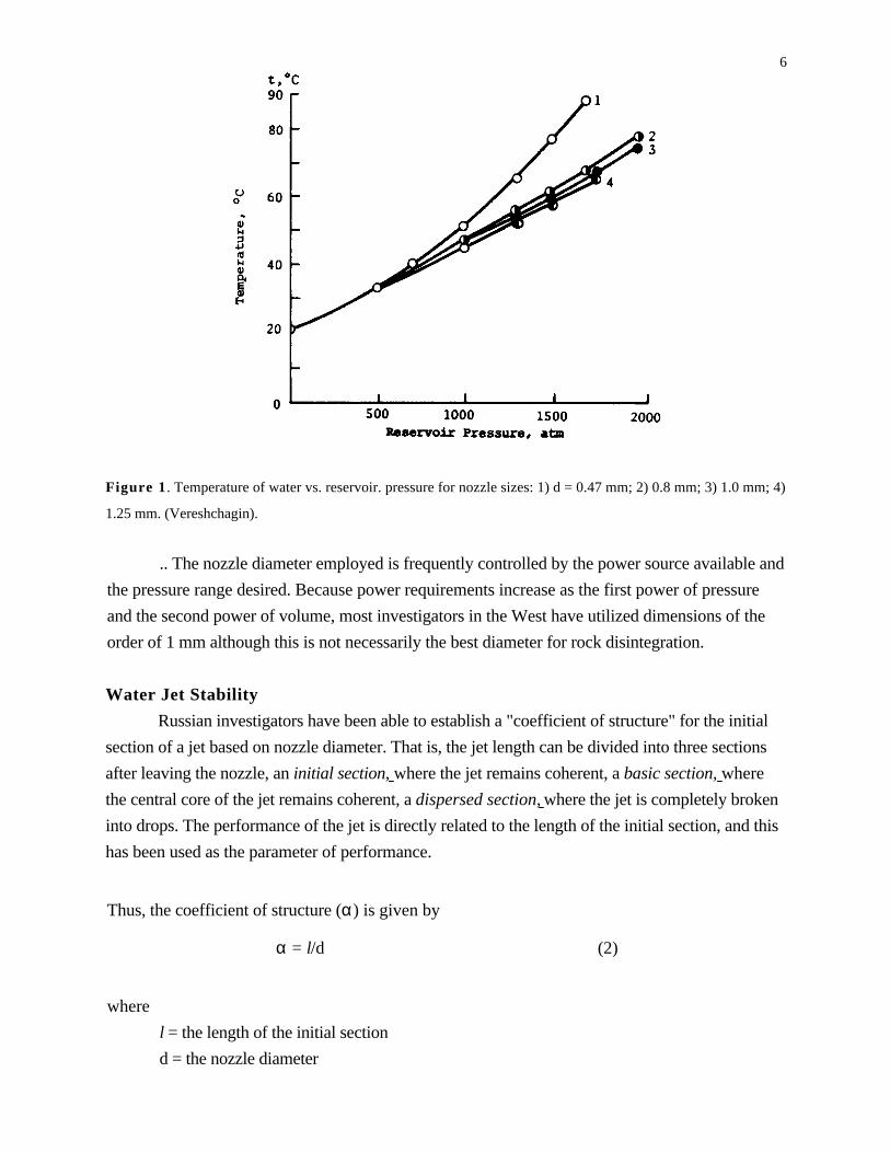
6
Figure 1 . Temperature of water vs. reservoir. pressure for nozzle sizes: 1) d = 0.47 mm; 2) 0.8 mm; 3) 1.0 mm; 4)
1.25 mm. (Vereshchagin).
.. The nozzle diameter employed is frequently controlled by the power source available and
the pressure range desired. Because power requirements increase as the first power of pressure
and the second power of volume, most investigators in the West have utilized dimensions of the
order of 1 mm although this is not necessarily the best diameter for rock disintegration.
Water Jet Stability
Russian investigators have been able to establish a "coefficient of structure" for the initial
section of a jet based on nozzle diameter. That is, the jet length can be divided into three sections
after leaving the nozzle, an initial section, where the jet remains coherent, a basic section, where
the central core of the jet remains coherent, a dispersed section, where the jet is completely broken
into drops. The performance of the jet is directly related to the length of the initial section, and this
has been used as the parameter of performance.
Thus, the coefficient of structure (α) is given by
α = l/d (2)
where
l = the length of the initial section
d = the nozzle diameter
7
At low pressures and large nozzle diameters (50 - 200 mm) Royer (Ref. 18) found that α is
approximately equal to a constant value (20). Khynkin (Ref. 19) modified this to the form
α = A - B x R (3)
where A and B are constants of order 75 to 100 and 10 to 25 x 10-6 respectively and R is the
Reynolds number of the jet.
At higher pressures the equation is similar, but the values of the constants change, Kuklin
and Shtukaturov (Ref. 20) giving:
α = 0.25α1 + 1.2 x 10⁻⁸ α2 R (4)
where
α1 = the hydraulic quantity coefficient of the nozzle
α 2 = the hydraulic quantity coefficient of the delivery system
The basic causes of hypervelocity jet instability are not clearly defined.Pai (Ref. 21) has
summarized theoretical analyses of several types of jets and their stability, including: (1) ideal
inviscid, noncompressible subsonic flow; (2) inviscid compressible subsonic flow, (3) laminar,
incompressible, viscous flow, (4) turbulent, incompressible flow, (5) turbulent, compressible
flow, and (6) supersonic, compressible, inviscid flow, including shock waves and neglecting heat
conduction. Only the latter (6) appears to be applicable to hypervelocity jets.
Supersonic (inviscid compressible) flow occurs when the medium/reservoir pressure ratio
is lower than a critical value, and the expansion and compression waves are accompanied by shock
waves. Sauer (Ref. 22) notes that when jet velocities are large and there is an increase in the ratio
of the stream velocity to the velocity of sound, the influence of the compressibility on the stream
lines becomes stronger. When the jet velocity exceeds the velocity of sound new phenomena
appear. Disturbances no longer propagate through the whole field of flow, but only in the
downstream region. There are continuous velocity and pressure changes, as well as continuous
changes of state characterized by "compression shocks". A mathematical difference lies in the fact
that the potential equation for subsonic flow is elliptic (for compressible media) and that for
supersonic flow is hyperbolic. Pai (Ref. 21) treats the case of a supersonic axisymmetric circular
jet. The flow equation is derived and a solution obtained in terms of Bessel functions.
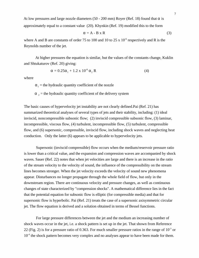
For large pressure differences between the jet and the medium an increasing number of
shock waves occur in the jet, i.e. a shock pattern is set up in the jet. That shown from Reference
22 (Fig. 2) is for a pressure ratio of 0.363. For much smaller pressure ratios in the range of 10-3 or
10-4 the shock pattern becomes very complex and no analyses appear to have been made for them.
8Such shocks undoubtedly contribute markedly to jet instability. Thus, while no complete theory
has been developed for large Mach numbers, (1) turbulence, (2) air friction, and (3) shock waves
in the jet are critical factors in jet stability.
Figure 2. Supersonic parallel axisymmetric jet into medium at lower pressure at Mach 1.305 showing generated
and reflected shock waves.
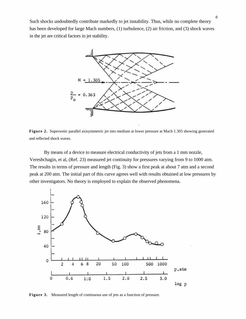
By means of a device to measure electrical conductivity of jets from a 1 mm nozzle,
Vereshchagin, et al, (Ref. 23) measured jet continuity for pressures varying from 9 to 1000 atm.
The results in terms of pressure and length (Fig. 3) show a first peak at about 7 atm and a second
peak at 200 atm. The initial part of this curve agrees well with results obtained at low pressures by
other investigators. No theory is employed to explain the observed phenomena.
Figure 3. Measured length of continuous use of jets as a function of pressure.
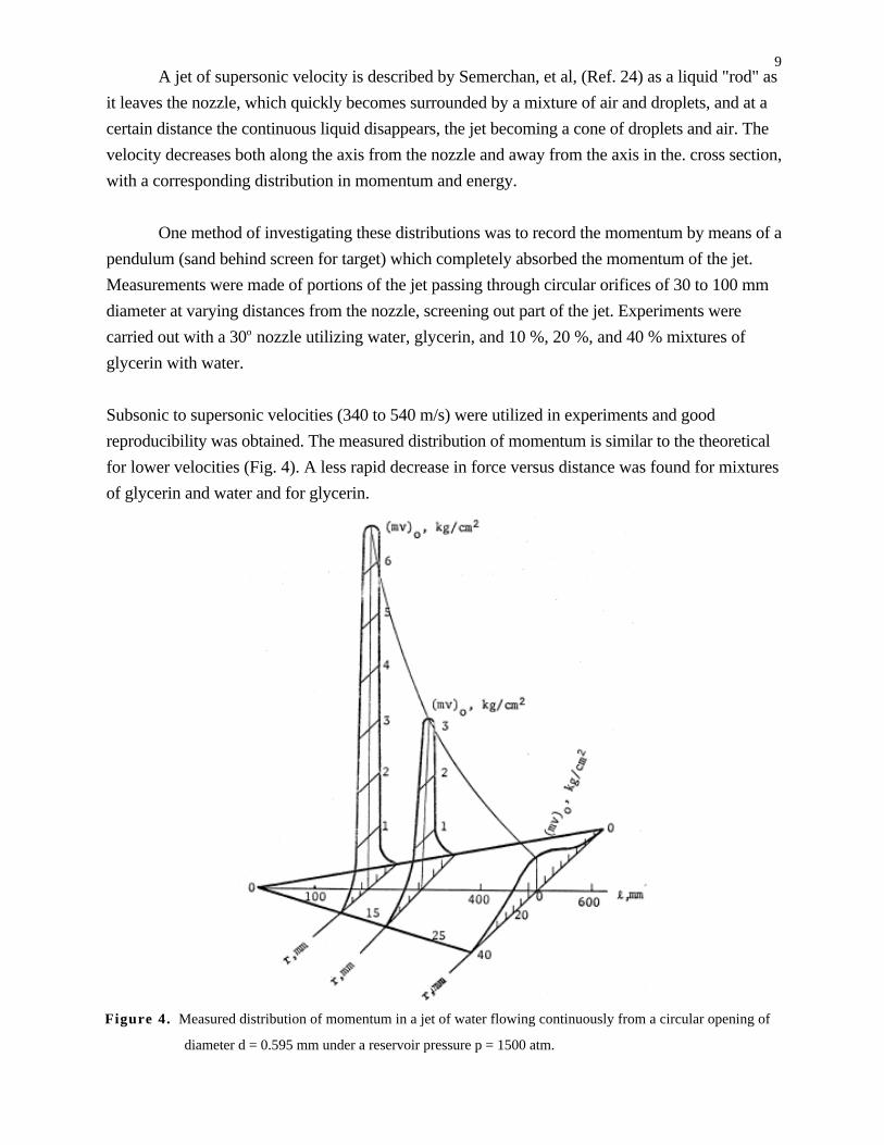
9A jet of supersonic velocity is described by Semerchan, et al, (Ref. 24) as a liquid "rod" as
it leaves the nozzle, which quickly becomes surrounded by a mixture of air and droplets, and at a
certain distance the continuous liquid disappears, the jet becoming a cone of droplets and air. The
velocity decreases both along the axis from the nozzle and away from the axis in the. cross section,
with a corresponding distribution in momentum and energy.
One method of investigating these distributions was to record the momentum by means of a
pendulum (sand behind screen for target) which completely absorbed the momentum of the jet.
Measurements were made of portions of the jet passing through circular orifices of 30 to 100 mm
diameter at varying distances from the nozzle, screening out part of the jet. Experiments were
carried out with a 30o nozzle utilizing water, glycerin, and 10 %, 20 %, and 40 % mixtures of
glycerin with water.
Subsonic to supersonic velocities (340 to 540 m/s) were utilized in experiments and good
reproducibility was obtained. The measured distribution of momentum is similar to the theoretical
for lower velocities (Fig. 4). A less rapid decrease in force versus distance was found for mixtures
of glycerin and water and for glycerin.
Figure 4. Measured distribution of momentum in a jet of water flowing continuously from a circular opening of
diameter d = 0.595 mm under a reservoir pressure p = 1500 atm.
10Leach and Walker (Ref. 7) studied the stability of jets from a 1 mm nozzle at pressures of 130 and
600 atm. Flash tube and spark photography showed a dispersing jet. X-ray photos, however,
indicated a continuous central core which contained most of the mass of the water, which confirms
the findings of Vereshchagin (Fig. 4). The pressure distribution of the cross section of the jet was
found (Ref. 7) to be represented by:
p = po +1
2⋅u2 1 − 3
r
R
2
+ 2r
R
3
(5)
where
ρ = water density
p = pressure at target
po= ambient pressure
r = radial distance
u = mean jet velocity
R = distance from where p =po
Which was in substantial agreement with their measured values and in qualitative agreement with
theories for low velocity jets.
In spite of dispersion and mixing, total impact pressure of jets was foundto be
approximately constant with distance by Zelenin (Ref. 14) for receiver pressures up to 1000 atm
(Table 1). However, for jets from a nozzle of 0.595 mm and a pressure of 1500 atm, Semerchan,
et al, (Ref. 24) found that the momentum and unit pressure decreased rapidly with distance (Fig.
4) in general agreement with theory. Thus, water jets should be most effective at or near zero
standoff.
Receiver Distance from Nozzle
Pressure, Atm 3 cm 5 cm 12 cm 25 cm 45 cm.
300 4.0 7.0 3.5 3.4 3.5
500 9.0 7.0 7.0 7.5 10.0
700 10.0 11.0 11.5 111.0 12.0
1,000 15.0 14.0 14.0 15.5 15.0
Table 1 Total Pressure of Jet with distance.
Rock Penetration
In 1960 Ostrovskii (Ref. 11) made a summary of developments in Russian methods of
drilling, with fragmentary information on high velocity jets. Tests were reported on limestone and
11dolomite with reservoir pressures of 5000 kg/cm2 and velocities to 1000 m/s. It was stated that
breaking of rocks by high velocity jets depends upon the physical-mechanical properties (not
defined), mineral composition, and small scale structural features. Strong (resistant) rocks such as
granite (Fig. 5), limestones and dolomites were slabbed off in larger fragments, resulting in the
formation of conical craters of apex angle greater than 90o. Sandstone was shattered without
appreciable spalling, resulting in a cylindrical crater, and the effects in clays were similar. Blocks
of hard rock (1 x 1.5 x 1 m) impacted by a pulsed jet were fractured as well as cratered.
Figure 5. Relation of volume of excavated cavity in granite to nozzle diameter by jets through a layer of water.
The effect of standoff on penetration of jets in air and in water for a granite target with a
uniaxial compressive strength of 2,000 kg/cm 2 (Fig. 6) indicates that the peak penetration is
obtained with 55 mm standoff for a combustion chamber pressure of 3,500 kg/cm 2, jet diameter
3.15 mm in air and 3.10 through a layer of water.
Figure 6. Depth of cut in granite vs. standoff, with water jets travelling in air and through a layer of water (nozzle
diameter, 3.15 mm).

12However, Farmer, et al, (Ref. 25) found that the greatest penetration at a rock-air interface
was achieved at zero standoff (Fig. 7), which differs from Russian results, possibly due to the
presence of the water layer.
Figure 7. Loss of penetration at increased standoff.
Crater diameters increased with an increase in stand-of f (Fig. 8) At low velocities there is
also a marked dependence of penetration on compressive strength (Fig. 9) . Water velocities had a
mean value of 2800 ft/sec, for these experiments, and the impact pressure, calculated f rom p =
ρcv, was 14 kilobars (p is density, c is sound velocity and v is particle velocity).
Figure 8. Increase in crater diameter with standoff.
Figure 9. Relationship between penetration and “static” compressive strength for rock at zero standoff.
13For three relatively soft rocks for velocities between .200 and 500 m/s (Fig. 10) transition
velocities were found between 250 and believed to be due to turbulence in the crater. It was found
that above a certain critical velocity the rate of penetration was less for higher velocities. The
penetration equation for the region above 300 m/s was found to be
h = kdc (vo/c) 2/3 (6)
In a comparison of jets and low velocity projectiles, Farmer, et al, (Ref. 15) suggest that
penetration is proportional to momentum:
h =k
am ⋅ vo (7)
where
m = mass of projectile
v0 = impact velocity
a = cross section of projectile
k = constant dependent on projectile and target properties
For relatively low pressures Maurer (Ref. 26) notes that the data of Farmer and Attewell
(Ref. 25) shows that (Table 2) the drilling rate increases and the specific drilling energy decreases
rapidly with increase of nozzle diameter from 1.19 mm but levels off just above 4.76 mm for
sandstone. Specific energy passes through a minimum at 6500 psi (Table 3) for Darley Dale
sandstone and about the same for Berea sandstone. Optimum pressure and nozzle diameter appear
to be functions of grain size, the strength of grain cementing materials and other factors.
Nozzle Diameter Water Pressure Hole Diameter Drilling Rate Power Output Specific Energy
(mm) (psi) (in) (ips) Hp Ft-lb/cu.in.
1.19 17,400 0.11 6.3 88 800,000
1.59 18,100 0.20 15.0 167 200,000
2.38 18,400 0.35 43.0 380 30,000
3.17 18,400 0.52 79.0 680 23,000
4.76 19,200 1.10 51.0 1640 18,000
Table 2 Effect of Nozzle Diameter on Hydraulic Drilling Rate in Darley Dale Sandstone. (Data from Farmer and
Attewell)
14
Figure 10. Rock penetration by water jet impact for three types of rock with varying nozzle diameters.
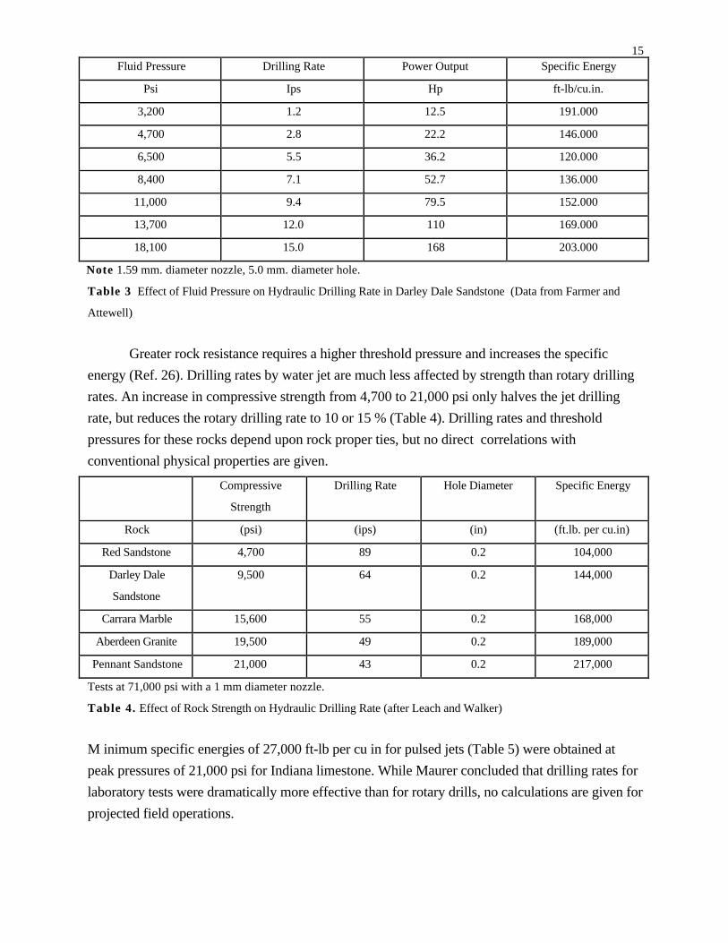
15Fluid Pressure Drilling Rate Power Output Specific Energy
Psi Ips Hp ft-lb/cu.in.
3,200 1.2 12.5 191.000
4,700 2.8 22.2 146.000
6,500 5.5 36.2 120.000
8,400 7.1 52.7 136.000
11,000 9.4 79.5 152.000
13,700 12.0 110 169.000
18,100 15.0 168 203.000
Note 1.59 mm. diameter nozzle, 5.0 mm. diameter hole.
Table 3 Effect of Fluid Pressure on Hydraulic Drilling Rate in Darley Dale Sandstone (Data from Farmer and
Attewell)
Greater rock resistance requires a higher threshold pressure and increases the specific
energy (Ref. 26). Drilling rates by water jet are much less affected by strength than rotary drilling
rates. An increase in compressive strength from 4,700 to 21,000 psi only halves the jet drilling
rate, but reduces the rotary drilling rate to 10 or 15 % (Table 4). Drilling rates and threshold
pressures for these rocks depend upon rock proper ties, but no direct correlations with
conventional physical properties are given.
Compressive
Strength
Drilling Rate Hole Diameter Specific Energy
Rock (psi) (ips) (in) (ft.lb. per cu.in)
Red Sandstone 4,700 89 0.2 104,000
Darley Dale
Sandstone
9,500 64 0.2 144,000
Carrara Marble 15,600 55 0.2 168,000
Aberdeen Granite 19,500 49 0.2 189,000
Pennant Sandstone 21,000 43 0.2 217,000
Tests at 71,000 psi with a 1 mm diameter nozzle.
Table 4. Effect of Rock Strength on Hydraulic Drilling Rate (after Leach and Walker)
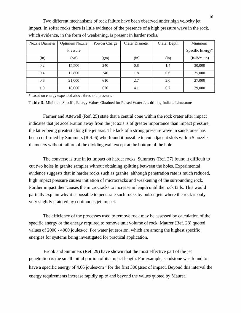
M inimum specific energies of 27,000 ft-lb per cu in for pulsed jets (Table 5) were obtained at
peak pressures of 21,000 psi for Indiana limestone. While Maurer concluded that drilling rates for
laboratory tests were dramatically more effective than for rotary drills, no calculations are given for
projected field operations.
16Two different mechanisms of rock failure have been observed under high velocity jet
impact. In softer rocks there is little evidence of the presence of a high pressure wave in the rock,
which evidence, in the form of weakening, is present in harder rocks.
Nozzle Diameter Optimum Nozzle
Pressure
Powder Charge Crater Diameter Crater Depth Minimum
Specific Energy*
(in) (psi) (gm) (in) (in) (ft-lb/cu.in)
0.2 15,500 240 0.8 1.4 30,000
0.4 12,800 340 1.8 0.6 35,000
0.6 21,000 610 2.7 2.0 27,000
1.0 18,000 670 4.1 0.7 29,000
* based on energy expended above threshold pressure.
Table 5. Minimum Specific Energy Values Obtained for Pulsed Water Jets drilling Indiana Limestone
Farmer and Attewell (Ref. 25) state that a central cone within the rock crater after impact
indicates that jet acceleration away from the jet axis is of greater importance than impact pressure,
the latter being greatest along the jet axis. The lack of a strong pressure wave in sandstones has
been confirmed by Summers (Ref. 6) who found it possible to cut adjacent slots within 5 nozzle
diameters without failure of the dividing wall except at the bottom of the hole.
The converse is true in jet impact on harder rocks. Summers (Ref. 27) found it difficult to
cut two holes in granite samples without obtaining splitting between the holes. Experimental
evidence suggests that in harder rocks such as granite, although penetration rate is much reduced,
high impact pressure causes initiation of microcracks and weakening of the surrounding rock.
Further impact then causes the microcracks to increase in length until the rock fails. This would
partially explain why it is possible to penetrate such rocks by pulsed jets where the rock is only
very slightly cratered by continuous jet impact.
The efficiency of the processes used to remove rock may be assessed by calculation of the
specific energy or the energy required to remove unit volume of rock. Maurer (Ref. 28) quoted
values of 2000 - 4000 joules/cc. For water jet erosion, which are among the highest specific
energies for systems being investigated for practical application.
Brook and Summers (Ref. 29) have shown that the most effective part of the jet
penetration is the small initial portion of its impact length. For example, sandstone was found to
have a specific energy of 4.06 joules/cm 3 for the first 300 µsec of impact. Beyond this interval the
energy requirements increase rapidly up to and beyond the values quoted by Maurer.
17The results Singh (Ref. 30) reported from Voytsekhovskii (Ref. 31) and Cooley (Ref. 2)
also show that low values of between 60 and 320 joules/cm 3 are obtained for very short duration
jets. Singh quotes specific energies of 8 x 10 4 to 8 x 10 6 joules/cm 3 for hydraulic erosion, a
process similar to continuous jet penetration. This suggests that pulsed jets are more likely to be
effective than continuous jets and this has been verified experimentally by Konyashin and Veselev
(Ref. 8), and Brook and Summers (Ref. 29).
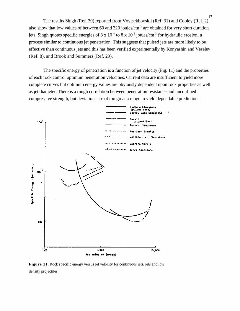
The specific energy of penetration is a function of jet velocity (Fig. 11) and the properties
of each rock control optimum penetration velocities. Current data are insufficient to yield more
complete curves but optimum energy values are obviously dependent upon rock properties as well
as jet diameter. There is a rough correlation between penetration resistance and unconfined
compressive strength, but deviations are of too great a range to yield dependable predictions.
Figure 11 . Rock specific energy versus jet velocity for continuous jets, jets and low
density projectiles.
18Rock Cutting and Breakage
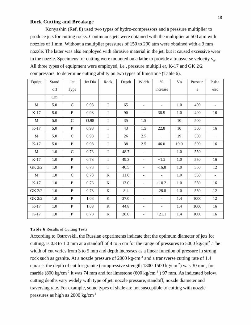
Konyashin (Ref. 8) used two types of hydro-compressors and a pressure multiplier to
produce jets for cutting rocks. Continuous jets were obtained with the multiplier at 500 atm with
nozzles of 1 mm. Without a multiplier pressures of 150 to 200 atm were obtained with a 3 mm
nozzle. The latter was also employed with abrasive material in the jet, but it caused excessive wear
in the nozzle. Specimens for cutting were mounted on a lathe to provide a transverse velocity vn.
All three types of equipment were employed, i.e., pressure multipli er, K-17 and GK 2/2
compressors, to determine cutting ability on two types of limestone (Table 6).
Equipt. Stand
off
Jet
Type
Jet Dia Rock Depth Width %
increase
Vn Pressur
e
Pulse
/sec
Cm
M 5.0 C 0.98 I 65 - - 1.0 400 -
K-17 5.0 P 0.98 I 90 - 38.5 1.0 400 16
M 5.0 C O.98 I 35 1.5 - 10 500 -
K-17 5.0 P 0.98 I 43 1.5 22.8 10 500 16
M 5.0 C 0.98 I 26 2.5 _ 19 500 _
K-17 5.0 P 0.98 I 38 2.5 46.0 19.0 500 16
M 1.0 C 0.73 I 48.7 - - 1.0 550 -
K-17 1.0 P 0.73 I 49.3 - +1.2 1.0 550 16
GK 2/2 1.0 P 0.73 I 40.5 - -16.8 1.0 550 12
M 1.0 C 0.73 K 11.8 - - 1.0 550 -
K-17 1.0 P 0.73 K 13.0 - +10.2 1.0 550 16
GK 2/2 1.0 P 0.73 K 8.4 - -28.8 1.0 550 12
GK 2/2 1.0 P 1.08 K 37.0 - - 1.4 1000 12
K-17 1.0 P 1.08 K 44.8 - - 1.4 1000 16
K-17 1.0 P 0.78 K 28.0 - +21.1 1.4 1000 16
Table 6 Results of Cutting Tests
According to Ostrovskii, the Russian experiments indicate that the optimum diameter of jets for
cutting, is 0.8 to 1.0 mm at a standoff of 4 to 5 cm for the range of pressures to 5000 kg/cm2 .The
width of cut varies from 3 to 5 mm and depth increases as a linear function of pressure in strong
rock such as granite. At a nozzle pressure of 2000 kg/cm 2 and a transverse cutting rate of 1.4
cm/sec. the depth of cut for granite (compressive strength 1300-1500 kg/cm 2) was 30 mm, for
marble (800 kg/cm 2 it was 74 mm and for limestone (600 kg/cm 2 ) 97 mm. As indicated below,
cutting depths vary widely with type of jet, nozzle pressure, standoff, nozzle diameter and
traversing rate. For example, some types of shale are not susceptible to cutting with nozzle
pressures as high as 2000 kg/cm 2
19The breaking power of jets was also investigated with nozzles of 1.11 and 0.98 mm at
1,000 atm pressure and a standoff of 5 cm. Tough limestones were not broken, but holes were
drilled. Granite and sandstone blocks 5 by 30 by 10 cm were broken by a jet impacting at the
center of the larger face. Marble blocks 40 by 30 by 30 cm, were likewise broken. However, some
hard and brittle rocks were not broken by jets impacting from 30 to 60 seconds.
For a given traversing speed there is a critical specific pressure for a given rock at which slot
cutting is initiated, which is directly proportional to the Protodyakonov coefficient of hardness of
the rock (5), i.e.
Pmin = 13 f (8)
and the corresponding critical receiver pressure is
PC = 25 f (9)
It was also found that the product of the working area of a jet, wl, and the cut depth h is constant
for a given material and is independent of standoff. Also, h x w1 is inversely proportional to f.
Thus, for P = 1000 atm, v =1 cm/sec. and d=1 mm, for rocks of f = 5 to 16,
h w f = 0.5 (10)
The K-1-7 pulsating jets gave better results than the constant jets from the multiplier, and
pulsating jets from the GK 2/2 were poorer than both the others. Further tests were conducted with
the K-17 without a receiver (last 1ine Table 6). Due to the loss through release valves the actual
relative power or efficiency of the jet could not be obtained. When vn was increased to about 20
cm/sec only conical holes were formed with pulsating jets. For such high transverse speeds higher
jet velocities were recommended. It was concluded that pulsed jets may be inadequate for cutting
rock, but may be better for rock breakage. The production of pulsed jets directly by compressors
was found to increase the breakage of machinery parts.
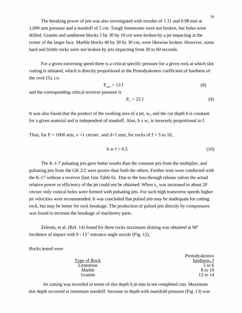
Zelenin, et al, (Ref. 14) found for three rocks maximum slotting was obtained at 90o
incidence of impact with 9 - 13 o entrance angle nozzle (Fig. 12).
Rocks tested were
Protodyakonov Type of Rock hardness, f
Limestone 5 to 6Marble 8 to 10Granite 12 to 14
Jet cutting was recorded in terms of slot depth h in mm in ten completed cuts. Maximum
slot depth occurred at minimum standoff. Increase in depth with manifold pressure (Fig. 13) was
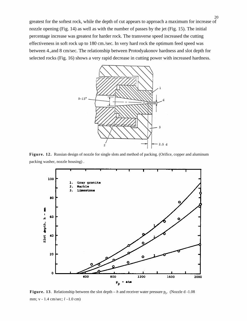
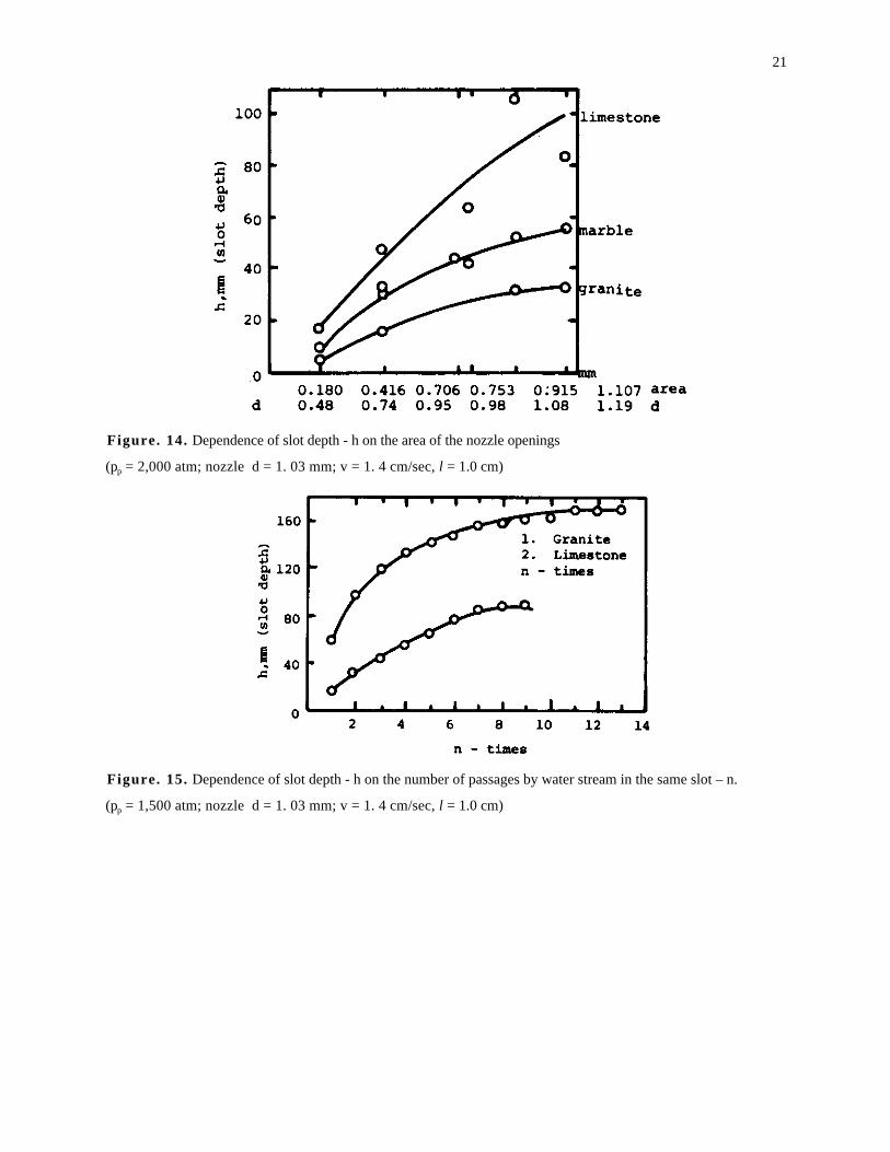
20greatest for the softest rock, while the depth of cut appears to approach a maximum for increase of
nozzle opening (Fig. 14) as well as with the number of passes by the jet (Fig. 15). The initial
percentage increase was greatest for harder rock. The transverse speed increased the cutting
effectiveness in soft rock up to 180 cm./sec. In very hard rock the optimum feed speed was
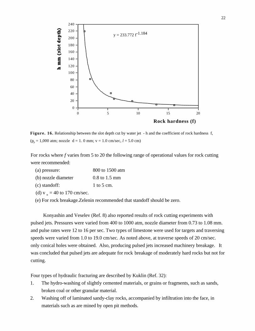
between 4.,and 8 cm/sec. The relationship between Protodyakonov hardness and slot depth for
selected rocks (Fig. 16) shows a very rapid decrease in cutting power with increased hardness.
Figure. 12. Russian design of nozzle for single slots and method of packing. (Orifice, copper and aluminum
packing washer, nozzle housing) .
Figure. 13 . Relationship between the slot depth – h and receiver water pressure pp. (Nozzle d -1.08
mm; v - 1.4 cm/sec; l –1.0 cm)
21
Figure. 14. Dependence of slot depth - h on the area of the nozzle openings
(pp = 2,000 atm; nozzle d = 1. 03 mm; v = 1. 4 cm/sec, l = 1.0 cm)
Figure. 15. Dependence of slot depth - h on the number of passages by water stream in the same slot – n.
(pp = 1,500 atm; nozzle d = 1. 03 mm; v = 1. 4 cm/sec, l = 1.0 cm)
22
0
20
40
60
80
100
120
140
160
180
200
220
240
0 5 10 15 20
Rock hardness (f)
y = 233.772 f-1.184
Figure. 16. Relationship between the slot depth cut by water jet - h and the coefficient of rock hardness f,
(pp = 1,000 atm; nozzle d = 1. 0 mm; v = 1.0 cm/sec, l = 5.0 cm)
For rocks where f varies from 5 to 20 the following range of operational values for rock cutting
were recommended:
(a) pressure: 800 to 1500 atm
(b) nozzle diameter 0.8 to 1.5 mm
(c) standoff: 1 to 5 cm.
(d) v n = 40 to 170 cm/sec.
(e) For rock breakage.Zelenin recommended that standoff should be zero.
Konyashin and Veselev (Ref. 8) also reported results of rock cutting experiments with
pulsed jets. Pressures were varied from 400 to 1000 atm, nozzle diameter from 0.73 to 1.08 mm.
and pulse rates were 12 to 16 per sec. Two types of limestone were used for targets and traversing
speeds were varied from 1.0 to 19.0 cm/sec. As noted above, at traverse speeds of 20 cm/sec.
only conical holes were obtained. Also, producing pulsed jets increased machinery breakage. It
was concluded that pulsed jets are adequate for rock breakage of moderately hard rocks but not for
cutting.
Four types of hydraulic fracturing are described by Kuklin (Ref. 32):
1. The hydro-washing of slightly cemented materials, or grains or fragments, such as sands,
broken coal or other granular material.
2. Washing off of laminated sandy-clay rocks, accompanied by infiltration into the face, in
materials such as are mined by open pit methods.

233. Hydrofracturing of cracked or fragile rocks due to cutting action and pressure, particularly by
pulsed jets, characterized by large spalls or fragments.
4. The cutting of dense or lengthy fractional rocks by pulsed or continuous jets, characterized by
formation of small fragments, utilizing pressures to 2500 atmospheres.
Leach and Walker (Ref. 7) studied the effect of 1 mm water jets at about 1000 m/sec (Mach
number 3.5) on cubes of three sandstones, a marble and a granite. Compressive strength of the red
sandstone (Rss) 330 atm; Darley Dale sandstone (DDss) 670 atm, Pennant sandstone (Pss)1460
atm, Carrara marble (Cm)1100 atm, and Aberdeen granite (Ag) 1370 atm.
Jets usually produced a hole, with occasional large cracks or shallow craters. The holes for
all rocks were 5 ± 1 mm diameter. For harder rocks penetration did not take place below a critical
pressure of 2000 atm. Hole diameter did not vary significantly with depth.
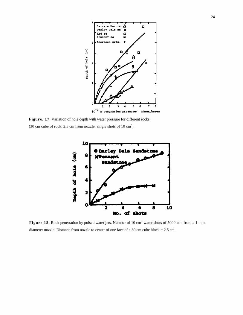
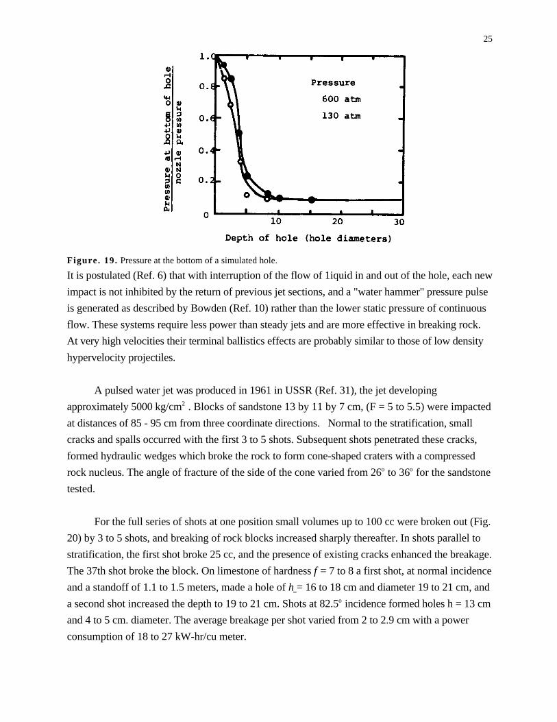
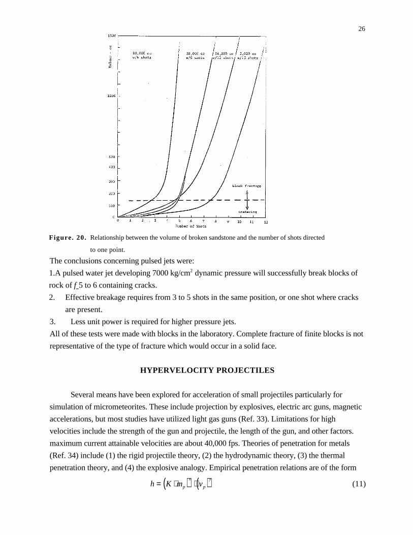
Rock strength affects hole depth, which increases with pressure (Fig. 17). Repeated shots at
5000 atm suggest a critical depth for DDss, (Fig. 18). Simulated pressures (Fig. 19) at the hole
bottoms were measured for 130 and 600 atm nozzles with a special device and were found to
decrease to a constant value of about one-tenth the pump pressure for hole depth greater than 10
hole diameters. A similar phenomenon is thought to occur for pressures of 2000 atm to account for
limiting hole depths.
Assuming spaced geometrical water jet cutting normal and parallel to a face of rock, an
estimate of 40 kg/min for Rss was estimated, which production was not as great as mechanical
methods for the same horsepower (500) at the nozzle outlet.
Aside from the report of breakage of rock by pulsed jets by Zelenin (Ref. 14), Brook and
Summers (Ref. 29), and Cooley (Ref. 2) there is no detailed description of the mechanics of
pulsed jet production or theory available in the literature. Two types of pulsed jets have been used,
those where the pressure of a continuous jet is allowed to fluctuate, controlled either by use of a
small pump manifold or mechanically, and where the jet flow is intermittently broken. Also, very
high ballistically generated jets may be considered to be single pulses.
24
Figure. 17 . Variation of hole depth with water pressure for different rocks.
(30 cm cube of rock, 2.5 cm from nozzle, single shots of 10 cm3).
Figure 18. Rock penetration by pulsed water jets. Number of 10 cm3 water shots of 5000 atm from a 1 mm,
diameter nozzle. Distance from nozzle to center of one face of a 30 cm cube block = 2.5 cm.
25
Figure. 19. Pressure at the bottom of a simulated hole.
It is postulated (Ref. 6) that with interruption of the flow of 1iquid in and out of the hole, each new
impact is not inhibited by the return of previous jet sections, and a "water hammer" pressure pulse
is generated as described by Bowden (Ref. 10) rather than the lower static pressure of continuous
flow. These systems require less power than steady jets and are more effective in breaking rock.
At very high velocities their terminal ballistics effects are probably similar to those of low density
hypervelocity projectiles.
A pulsed water jet was produced in 1961 in USSR (Ref. 31), the jet developing
approximately 5000 kg/cm2 . Blocks of sandstone 13 by 11 by 7 cm, (F = 5 to 5.5) were impacted
at distances of 85 - 95 cm from three coordinate directions. Normal to the stratification, small
cracks and spalls occurred with the first 3 to 5 shots. Subsequent shots penetrated these cracks,
formed hydraulic wedges which broke the rock to form cone-shaped craters with a compressed
rock nucleus. The angle of fracture of the side of the cone varied from 26o to 36o for the sandstone
tested.
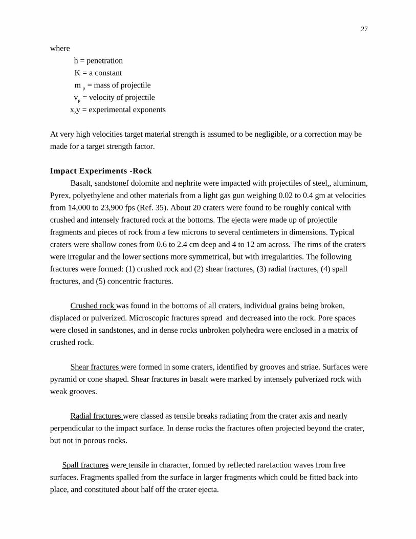
For the full series of shots at one position small volumes up to 100 cc were broken out (Fig.
20) by 3 to 5 shots, and breaking of rock blocks increased sharply thereafter. In shots parallel to
stratification, the first shot broke 25 cc, and the presence of existing cracks enhanced the breakage.
The 37th shot broke the block. On limestone of hardness f = 7 to 8 a first shot, at normal incidence
and a standoff of 1.1 to 1.5 meters, made a hole of h = 16 to 18 cm and diameter 19 to 21 cm, and
a second shot increased the depth to 19 to 21 cm. Shots at 82.5o incidence formed holes h = 13 cm
and 4 to 5 cm. diameter. The average breakage per shot varied from 2 to 2.9 cm with a power
consumption of 18 to 27 kW-hr/cu meter.
26
Figure. 20. Relationship between the volume of broken sandstone and the number of shots directed
to one point.
The conclusions concerning pulsed jets were:
1.A pulsed water jet developing 7000 kg/cm2 dynamic pressure will successfully break blocks of
rock of f 5 to 6 containing cracks.
2. Effective breakage requires from 3 to 5 shots in the same position, or one shot where cracks
are present.
3. Less unit power is required for higher pressure jets.
All of these tests were made with blocks in the laboratory. Complete fracture of finite blocks is not
representative of the type of fracture which would occur in a solid face.
HYPERVELOCITY PROJECTILES
Several means have been explored for acceleration of small projectiles particularly for
simulation of micrometeorites. These include projection by explosives, electric arc guns, magnetic
accelerations, but most studies have utilized light gas guns (Ref. 33). Limitations for high
velocities include the strength of the gun and projectile, the length of the gun, and other factors.
maximum current attainable velocities are about 40,000 fps. Theories of penetration for metals
(Ref. 34) include (1) the rigid projectile theory, (2) the hydrodynamic theory, (3) the thermal
penetration theory, and (4) the explosive analogy. Empirical penetration relations are of the form
h = K ⋅ mp( )x⋅ vp( )y
(11)
27
where
h = penetration
K = a constant
m p = mass of projectile
vp = velocity of projectile
x,y = experimental exponents
At very high velocities target material strength is assumed to be negligible, or a correction may be
made for a target strength factor.
Impact Experiments -Rock
Basalt, sandstonef dolomite and nephrite were impacted with projectiles of steel,, aluminum,
Pyrex, polyethylene and other materials from a light gas gun weighing 0.02 to 0.4 gm at velocities
from 14,000 to 23,900 fps (Ref. 35). About 20 craters were found to be roughly conical with
crushed and intensely fractured rock at the bottoms. The ejecta were made up of projectile
fragments and pieces of rock from a few microns to several centimeters in dimensions. Typical
craters were shallow cones from 0.6 to 2.4 cm deep and 4 to 12 am across. The rims of the craters
were irregular and the lower sections more symmetrical, but with irregularities. The following
fractures were formed: (1) crushed rock and (2) shear fractures, (3) radial fractures, (4) spall
fractures, and (5) concentric fractures.
Crushed rock was found in the bottoms of all craters, individual grains being broken,
displaced or pulverized. Microscopic fractures spread and decreased into the rock. Pore spaces
were closed in sandstones, and in dense rocks unbroken polyhedra were enclosed in a matrix of
crushed rock.
Shear fractures were formed in some craters, identified by grooves and striae. Surfaces were
pyramid or cone shaped. Shear fractures in basalt were marked by intensely pulverized rock with
weak grooves.
Radial fractures were classed as tensile breaks radiating from the crater axis and nearly
perpendicular to the impact surface. In dense rocks the fractures often projected beyond the crater,
but not in porous rocks.
Spall fractures were tensile in character, formed by reflected rarefaction waves from free
surfaces. Fragments spalled from the surface in larger fragments which could be fitted back into
place, and constituted about half off the crater ejecta.
28Concentric fractures were present about the rims of some craters, and extended only a fraction of a
millimeter below the rock surface.
High speed photography indicated that luminescence was generated at the moment of
impact, and as the projectile penetrated a bowl-shaped spray of ejecta grew rapidly with a speed
comparable to that of the projectile. The base of the ejecta expanded into a dome which exhibited
irregularities related to the large spall fragments, the outermost of which were sometimes not
ejected from the crater.
Penetration was postulated to be by means of plastic flow, crushing and shearing, under
hydrodynamic conditions. Tensile fractures were formed later and spalling subsequent to reflection
of waves. Many of the features described are also present in craters created by high explosives.
Gault and Heitowit (Ref. 36) made an approximate analysis of the energy partitioning in the
impact of aluminum projectiles on basalt. Their observations and calculations indicate th e fallacy
of explosion theory of impact, i.e. that when the kinetic energy of the projectile is equal to the
energy of vaporization an explosion occurs. Experiments show that only a small portion of the
energy is trapped as heat of fusion and/or vaporization. Analyses were based upon both theory
and observations with a high speed camera.
The initial stage of impact is considered to be a problem in one-dimensional flow which is
described by the Rankine-Hugoniot equations. From these and Hugoniot data for aluminum and
basalt the energy retained by the projectile and that delivered to the target are expressed in terms of
velocities and shock parameters. The resulting equations indicate that, except for impact of similar
materials, the retained projectile energy will never equal that delivered to the target, but for higher
density projectiles the fraction of energy delivered becomes smaller.
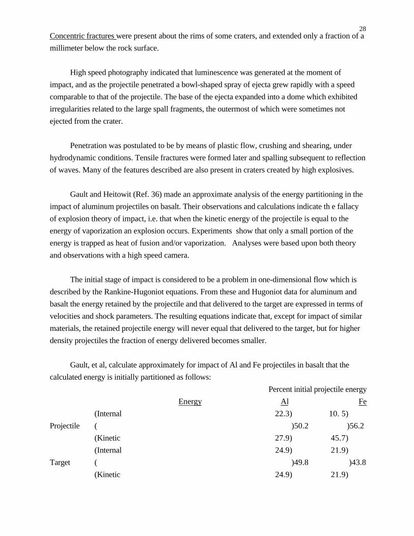
Gault, et al, calculate approximately for impact of Al and Fe projectiles in basalt that the
calculated energy is initially partitioned as follows:
Percent initial projectile energy
Energy Al Fe
(Internal 22.3) 10. 5)
Projectile ( )50.2 )56.2
(Kinetic 27.9) 45.7)
(Internal 24.9) 21.9)
Target ( )49.8 )43.8
(Kinetic 24.9) 21.9)
29After the initial partitioning, the process is assumed to be analogous to the compression of a
spring. Once the force of the projectile is spent the compressed target mass expands in release of
the compression (rarefaction.)
By further use of the Hugoniot curve and isentrope it is shown that for a velocity of 6.25
km/sec, 19 percent of the increase in specific internal energy, or 4 percent of the total kinetic
energy, is, expended in irreversible heating. This is enough to partially melt the projectile.
Observed melting of projectiles indicates that the above procedure predicts about one-third of the
melting which actually takes place. For the target a hemispherical shock is assumed and combined
with an appropriate experimental Hugoniot. A pressure gradient is approximated and irreversible
heat calculated from appropriate equations by numerical methods. The estimated amounts of heat
are sufficient to fuse minerals in basalt, but not to vaporize them.
Comminution of the target consumes an important faction of the projectile kinetic energy.
This is approximated by calculating the new surface energy from a screen analysis of the particle
sizes of crater ejecta, and an approximation of the fracturing of target material around the crater. A
specific surface energy was assumed for basalt from known values for quartz and limestone. For a
given test it was found that about ten percent of the projectile energy was used in comminution of
ejected material. Additional crushing and fracturing of the target was estimated at a maximum of
ten percent.
Ejecta velocity distribution was estimated from high speed framing records. A numerical
summation process indicated that about 48 ±5 % of the kinetic energy of the projectile was
retained in the ejecta. The spallation of the rear of the target, together with the tensile strength of
basalt permitted calculation of elastic energy as being less than one percent of the total projectile
energy.
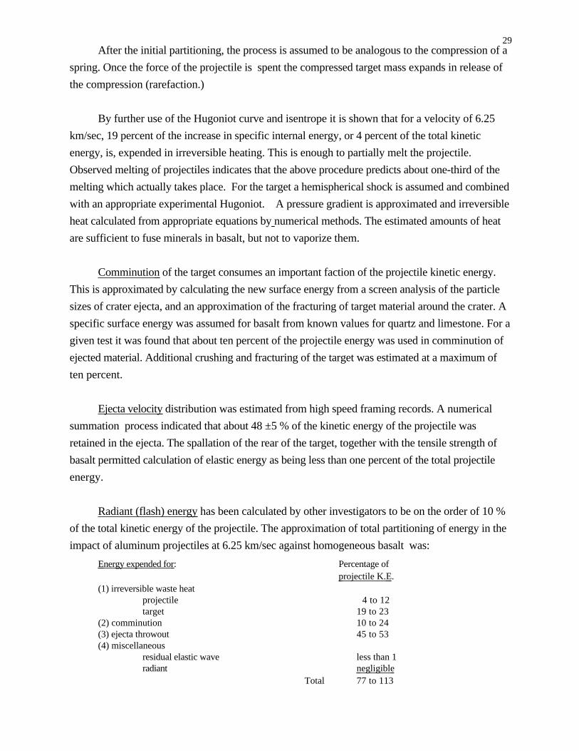
Radiant (flash) energy has been calculated by other investigators to be on the order of 10 %
of the total kinetic energy of the projectile. The approximation of total partitioning of energy in the
impact of aluminum projectiles at 6.25 km/sec against homogeneous basalt was:
Energy expended for : Percentage of projectile K.E .
(1) irreversible waste heatprojectile 4 to 12target 19 to 23
(2) comminution 10 to 24(3) ejecta throwout 45 to 53(4) miscellaneous
residual elastic wave less than 1radiant negligible
Total 77 to 113

30If the above approximations are reasonably accurate, then hypervelocity projectiles provide an
inefficient means of fracturing by elastic stress waves. Likewise, if ejecta is fine material,
considerable energy is consumed in comminution.
Moore, et al (Ref. 37) conducted a series of 38 impact experiments in basalt at normal incidence.
Aluminum, steel, and polyethylene projectiles of weight 0.0058 to 4.051 gm. were fired from
light gas guns, velocities varying from 0.88 to 7.3 km/sec and kinetic energies from 4.9 x 10⁸ to
7.4 x 10¹¹ erg.
Basalt properties were:
density 2.70 to 2.89 g/cm 3
compressive strength 1.56 to 3.69 x 10⁹ dynes/cm2
tensile strength 0.90 to 2.32 x 10⁸ dynes/cm 2
shear strength average computed 8.6 x 10⁸ dynes/cm 2
acoustic velocity 4.9 to 5.5 km/sec
A least squares fit of the data gave the following equation:
Me = 10−10.613 p
t
0.5
⋅ Ep
1.189 (12)
where
M e = mass of ejecta
ρ p = density of projectile
ρt = density of target
E p = energy of projectile
Target failure conditions were considered to be complex, and a comparison of cratering in
basalt with that in metals and water led Moore, et al, to the conclusion that tensile fracture plays a
dominant role in cratering in basalt. Spalling creates craters in rock, which are about ten times as
large as those in metal. Fluid impact theory predicts that the crater volume or ejected mass for
given materials should be proportional to the projectile energy. However, the results of these
experiments indicate that the ejected mass varies as the energy to 1.2 power. In other words, the
effective strength of basalt apparently decreases with crater size.
Moore, et al, (Ref . 38) compared the results of impact cratering in lead, copper, aluminum,
diatomaceous earth, water and basalt on an energy basis, for the same kinetic energy. The crater
volume for diatomaceous earth was largest, basalt next, then copper, aluminum and lead. If the
projectile energy is normalized adjusting for density and target strength, the basalt

31volumes are about three times the others, probably due to tensile spalling. Target strength at
high confining pressures is utilized as a criterion, although few data are available for the high
pressures involved (above 49 kilobars).
One theory of strength-size effects stipulates that rupture strength R is proportional to the
inverse of characteristic length to the inverse square root power for material with flaws:
R α l-0.5 (13)
or is proportional to mass M to the (-0.167) power:
R α M 0.167 (14)
Following the Charters-Summers theory (Ref. 39):
Me =Ep
2⋅Pt
s (15)
where
E p = projectile energy
Pt = target density
s = deformation strength of target
Equation (15) is modified for density ratios to give
Me = p
t
0.5
⋅Ep
2
⋅
t
s
(16)
Combining equation (15) with (14) gives
S = k ⋅ Me−0.167 (17)
where
k constant
and with equation (16)
Me0.833 = p
t
0.5
⋅Ep
2
⋅
t
k
(18)
which is in close agreement with the experimentally determined values.
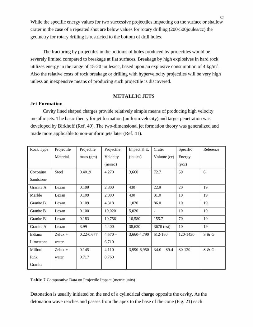
In a recent study Singh and Gregson (Ref. 30) impacted Indiana limestone and Milford pink
granite with low density Zelux projectiles containing water. Velocities varied from 4119 to 8760
m/s. The data obtained were compared with those from other sources (Refs. 6 and 20, Table 7)
and with rotary drilling.. Specific energies varied from 10 to about 200 joules/cc for effective
shots. Values of second shots in a crater gave energies comparable to first shots. Most of the
breakage by projectiles was found by Gault and Heitowit to be due to surface tensile slabbing.
32While the specific energy values for two successive projectiles impacting on the surface or shallow
crater in the case of a repeated shot are below values for rotary drilling (200-500joules/cc) the
geometry for rotary drilling is restricted to the bottom of drill holes.
The fracturing by projectiles in the bottoms of holes produced by projectiles would be
severely limited compared to breakage at flat surfaces. Breakage by high explosives in hard rock
utilizes energy in the range of 15-20 joules/cc, based upon an explosive consumption of 4 kg/m3.
Also the relative costs of rock breakage or drilling with hypervelocity projectiles will be very high
unless an inexpensive means of producing such projectile is discovered.
METALLIC JETS
Jet Formation
Cavity lined shaped charges provide relatively simple means of producing high velocity
metallic jets. The basic theory for jet formation (uniform velocity) and target penetration was
developed by Birkhoff (Ref. 40). The two-dimensional jet formation theory was generalized and
made more applicable to non-uniform jets later (Ref. 41).
Rock Type Projectile
Material
Projectile
mass (gm)
Projectile
Velocity
(m/sec)
Impact K.E.
(joules)
Crater
Volume (cc)
Specific
Energy
(j/cc)
Reference
Coconino
Sandstone
Steel 0.4019 4,270 3,660 72.7 50 6
Granite A Lexan 0.109 2,800 430 22.9 20 19
Marble Lexan 0.109 2,800 430 31.0 10 19
Granite B Lexan 0.109 4,318 1,020 86.0 10 19
Granite B Lexan 0.100 10,020 5,020 - 10 19
Granite B Lexan 0.183 10,756 10,580 155.7 70 19
Granite A Lexan 3.99 4,400 38,620 3670 (est) 10 19
Indiana
Limestone
Zelux +
water
0.22-0.677 4,570 –
6,710
3,660-4,790 512-180 120-1430 S & G
Milford
Pink
Granite
Zelux +
water
0.145 –
0.717
4,110 –
8,760
3,990-6,950 34.0 – 89.4 80-120 S & G
Table 7 Comparative Data on Projectile Impact (metric units)
Detonation is usually initiated on the end of a cylindrical charge opposite the cavity. As the
detonation wave reaches and passes from the apex to the base of the cone (Fig. 21) each

33successive element of the liner collapses under the pressure, moving at high velocity nearly
perpendicular to the original disintegrated liner. Flow converges to a junction on the cone axis,
then divides into two jets along the axis because the absolute velocity of both jets is in the direction
of detonation wave travel, and the divergence of the two jets results in a relatively slow velocity
one called the slug, and the fast jet is responsible for the penetration.
Figure. 21. Formation of jet and slug from a cone or. wedge- shaped liner whose sides collapse with constant
velocity Vo as a result of the explosion of a charge that was in contact with the outer surface. The solid lines show
conditions at an early instant of time, and the dotted lines show conditions after the walls have moved a distance
equal to the velocity V0 , for unit time.
The detonation pressure is many times the strength of the liner which is treated as an
incompressible ideal fluid. The velocity of a liner element is assumed to be constant throughout the
collapse process, and to change in direction only. at the junction. Bernoulli's equation may be
applied and application of conservation of mass, energy, and momentum yields for fast jet
velocity V
V V 0 csc (β/2) cos (α +δ-β/2) (19)
where
Vo is the collapse velocity and
α, β, and δ are the angles in Fig. 22.
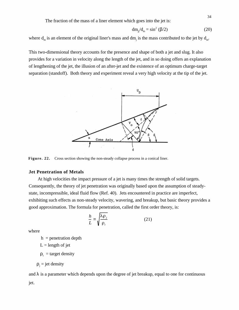
34The fraction of the mass of a liner element which goes into the jet is:
dmjj/dm = sin2 (β/2) (20)
where dm is an element of the original liner's mass and dmj is the mass contributed to the jet by dm.
This two-dimensional theory accounts for the presence and shape of both a jet and slug. It also
provides for a variation in velocity along the length of the jet, and in so doing offers an explanation
of lengthening of the jet, the illusion of an after-jet and the existence of an optimum charge-target
separation (standoff). Both theory and experiment reveal a very high velocity at the tip of the jet.
Figure. 22. Cross section showing the non-steady collapse process in a conical liner.
Jet Penetration of Metals
At high velocities the impact pressure of a jet is many times the strength of solid targets.
Consequently, the theory of jet penetration was originally based upon the assumption of steady-
state, incompressible, ideal fluid flow (Ref. 40). Jets encountered in practice are imperfect,
exhibiting such effects as non-steady velocity, wavering, and breakup, but basic theory provides a
good approximation. The formula for penetration, called the first order theory, is:
h
L= j
t
(21)
where
h = penetration depth
L = length of jet
ρt = target density
ρj = jet density
and λ is a parameter which depends upon the degree of jet breakup, equal to one for continuous
jet.
35The most obvious result of neglecting target strength is the implication that penetration is
independent of jet velocity and depends only on jet length. However, experiments have shown
that target strength does affect penetration. The rear of the jet travels at a relatively low velocity and
so exerts a relatively low pressure, which has been treated in various ways by Pack and Evans
(Ref. 42), and others (Refs. 43,44,45). The effect of heat losses also was considered by Cook
(Ref. 46). A very high radial pressure gradient outward from the jet as it penetrates is postulated.
Cook also extended these theories to determine the radius of the hole by assuming that the impulse
transferred to the target expands the hole laterally. However, most rocks do not yield in a
permanent plastic manner, hence, these theories do not apply.
Various recent theoretical developments account for such additional phenomena as optimum
standoff and approximate linear scaling of penetration with charge diameter. A reasonably accurate
prediction of penetration in many metals is possible for common standoff distances, and similar
laws will probably apply to rock and other brittle materials.
Design factors affecting the performance of shaped charges include explosive properties,
length of charge, liner material, liner thicknesses, apex angle, defects in liner, standoff and other
factors (Ref. 45).
Jet Penetration of Rock
The similarities which exist between impact effects of projectiles and jets are limited to the
initial portion of a jet approximately equal to a cylindrical projectile of the same mass and
geometry. In the development of some theories of penetration both spherical and cylindrical
projectiles have been considered as short jets. For projectiles at the instant of impact a shock wave
is propagated from the point of impact into both the target and the projectile. For a jet of metallic
particles the stream is made up of separated discrete segments and is not capable of propagating a
shock back into the jet, which forms a deep tapered hole in the target. In contrast very high
velocity projectiles form a hemispherical crater in ductile metals, while craters in rock are enlarged
by tensile spalling around the rim.
Lined shaped charges have been investigated (Ref. 47) to evaluate their effect in breaking
concrete blocks. Breakage by jets was less than that achieved by the same amount of explosives in
contact with the block, and considerably less than the same amount of explosive with a mud cap.
Hopkins and Kolsky (Ref. 48) point out that in penetration of jets into lucite, the velocity of both
the jet and penetration interface was so great that penetration was complete before a stress wave of
appreciable magnitude and duration would be initiated in the target. These observations indicate
that while the high speed jets are effective for penetration they may not be effective in breakage for
reasons similar to those proposed for hypervelocity projectiles.

36No detailed research data on the scaling of shaped charge penetration appear to have been
published, although developed equations, which are in fair agreement with observations, indicate
that the penetration depth should increase with the linear dimension of the charge. That is, the
familiar cube root law of explosives applies, which in turn implies energy scaling.
Rock penetration data from Austin (Refs. 49 and 50) and from experiments by Lewis and
Clark (Ref. 51) for which the density of target materials varies from approximately 1.0 to 9.0
show that (Fig. 23) the penetration increases more rapidly than the curve based upon the first order
theory. These data also tend to confirm the postulate that the effective strength appears to decrease
with crater size, that is, properties other than density have a strong effect upon penetrability.
Draper, et al, (Ref. 52) made a series of tests with standard M-2A3 and M3 military breaking
charges against greenstone and epidosite targets to determine possible applicability in conventional
drilling and blasting (Table 8). Depths of penetration were 12 to 14 inches in epidosite and 15 to
19 inches in greenstone for the M-2A3, and 32 inches and 29 inches, respectively, for the M3.
Both types of rock were unusually dense and of high strength. Greenstone had a density of 2.96
g/cc and a compressive strength of 44,200 psi and epidosite, 3.26 g/cc and 63,100 psi
respectively. Both rocks were also unusually hard to drill with both diamond drills and pneumatic
drills.

37
Fig. 23. Normalized rock penetration by shaped charge jets vs. square root of density ratio.
Nos. 1-25 4" diameter cast iron cones ρ p = 7.2;
Nos. 26-29 7" and 9.5” glass cones, ρp = 2.6. P = penetration, D charge diameter, ρ,, = jet
density, ρ t = target density, L = jet length.
Table 8 Charge Descriptions M- 2A3 M3
Wt. - total lbs. 15 40Wt. of explosive lbs. 11.5 28.5Type of explosive 50-50 pentoliteCone material glass steelCone angle ? ?Diameter 7 inches 9.5 inchesLength 12 inches 15.5~ inchesDesign Beehive BeehiveStandoff, normal 5.5 inches 15 inches

38Preliminary tests were made with shaped charges by the authors (1968) on a dolomite of
density 2.57 and a compressive strength of 11,900 psi. Selected results of the tests by the United
States Bureau of Mines, University of Missouri-Rolla and those by Austin (Ref. 50) are tabulated
as follows:
AUSTIN'S TESTS
Charge Description:Wt. of explosive 5.5Type of explosive C-3Cone material Cast ironCone angle 550Diameter 4 inchesLength ?Design Cylindrical and beehiveStandoff, normal 8± inches
Penetration: Cylindrical:Rhyolite 11-24 inchesQuartz mon. 16-34 inchesLimestone 8-10 inchesSandstone 23-26 inches
Beehive:Rhyolite 16-17
UNIVERSITY OF MISSOURI-ROLLA TESTS
Charge Description:Wt. of explosive 11 ounces and 3 poundsType of explosive C-4Cone material Cast ironCone angle 450 and 550
Diameter 1.5 and 3 inches*Length 4.5 and 6 inchesDesign Cylindricalk/d ratio 4 and 3*3 inch is a beehive shapePenetration Dolomite:
Charge Diameter, Explosive Weight l/d ratio Penetration1.5 11 oz. 4 10-12.5 in. (450)2 1 lb. 3 8-12.5 in. (550)3 2 lb. (beehive) 21-24 in. (550)
An examination of the above results indicates that:
(1) The M2A3 charge may be ineffective because of the low density glass liner.
(2) The U.S. Bureau of Mines tests were made on hard, dense, tough rocks and are much
stronger than average rocks encountered.
(3) With a steel liner the M3 charge was relatively effective in drilling holes..
(4) Factors other than density play a dominant role in penetration.

39(5) Cast iron and steel liners are not the most effective types that can be used. Copper and
other metals may give somewhat higher penetration.
(6) The military beehive charge is not necessarily an optimum design for commercial drilling
performance.
(7) Tests in dolomite showed penetrations of 1-1/8 inch diameter holes of up to 12 in/lb. M3
penetration varies from 0 .8 to 1. 0 inches per pound for 2-1/2 inch diameter holes and Austin's
tests showed from 2 to 7 inches of depth per pound.
The partitioning of the released explosive energy from a shaped charge has not been
quantitatively evaluated. For an unconfined explosive charge the kinetic energy of the products of
detonation is utilized in (1) deforming the cavity liner, (2) imparting kinetic energy to the jet and
liner, (3) in expanding against atmosphere pressure, and (4) in lost heat. A very small portion of
the total explosive energy in a charge is utilized in forming the jet, although no measurements have
been made. If the behavior of jets is similar to high velocity projectiles, much of the energy is
utilized in the reflected jet, the ejecta and crushing. Only a small amount is retained by the rock as
elastic wave energy. As the confinement of explosive is increased from zero, there is only a small
increase in the jet performance (Ref. 45).
Other methods of utilizing cumulation on a small scale (Ref. 53) and of shaped charges to
form large high velocity slugs (Ref. 54) are reported and may be of future interest.
SUMMARY
Three methods of hypervelocity attack on rock have been studied by various investigators.
High velocity water jet research has been carried out extensively in Russia and to a lesser degree in
Britain and the United States. Although the specific energy of rock disintegration is relatively small
and is comparable to conventional drilling, the cost of producing the jets and the heavy equipment
required have not lent themselves to application. Jet breakage, either by continuous or pulsed jets,
has not been shown to be effective on hard abrasive rocks in situ.
Hypervelocity projectiles of low and high densities have been employed to create small
craters in medium hard and hard rocks. Specific energy values again are comparable with
conventional drilling. However, rock breakage in situ would require very large numbers of shots,
and inexpensive adaptable means of producing projectiles have not been investigated.
Shaped charge jets have good penetrability and are relatively inexpensive to produce. Such
jets are not effective for breaking rock in situ,but show promise for drilling and blasting
procedures. Specific energy values have not been measured.
40In all of the above methods conventional properties of rock do not give accurate means of
predicting resistance to disintegration, although unconfined compressive strength is an
approximate measure for many types of rock.
REFERENCES
1. Rinehart, J.S., "Compilation of Dynamic Equation of State Data for Solids and Liquids,"
NOTS TP 3798,,May 1965.
2. Cooley, W.C., et al, "Design Studies of High Velocity Liquid Jet Equipment," Exotech Inc.,
Rept. TR-RD-021, Vol. 1, 1967.
3. Bridgman, P.W., "The Phase Diagram of Water to 45,060 kg/cm2 Jl. of Chem. Phys., Vol.
5, December 1937.
4. Walsh, J.M., and Rice, M.H., "Dynamic Compression of Liquids from Measurements of
Strong Shock Waves," Jl. of Chem. Phys., Vol. 26, April 1957.
5. Snay, H.G., and Rosenbaum, J.H., "Shock Wave Parameters in Fresh Water for Pressures
up to 95 Kilobars," NAVORD Report, 2383, 1952.
6. Summers, D.A., "Disintegration of Rock by High Pressure Jets," Ph.D. thesis, University of
Leeds, Leeds, England, 1968.
7. Leach, S.J., and Walker, G.L., "The Application of High Speed Liquid Jets to Cutting -
Some Aspects of Rock Cutting by High Speed Water Jets," Phil. Trans., Roy. Soc., London,
Vol. 260, 1966.
8. Konyashin, Yu G., and Veselev, G.M. , "Concerning the Use of Impulse Jets," Sci. Info.,
Inst. of Min.,,Vol. 20, 1963.
9. Vereshchagin, L.F., et al, "Effect of the Reservoir on the Flow of a Stream of Water at
Supersonic Speed," Soviet Physics-Tech. Physics, 1957.
10. Bowden, F.P., et al, "A Discussion on Deformation of Solids by the Impact of Liquids and
its Relation to Rain Drop Damage in Aircraft and Missiles, to Blade Erosion in Steam
Turbine, and to Erosion," Phil. Trans. Roy. Soc. of London, A, Vol. 260, July 1966.
11. Ostrovskii, A.P., "Deep Hole Drilling with Explosives," Gostoptikhizat, Moscow, 1960.
12. Yutkin, L., "Electrohydraulic Effect and Its Application in Mining," Stroitel nyye Materialy,
Izdeliya i Konstruktsii, 9, 1955.
13. Sims, J.S., et al, "A Study of External Augmentation of the Velocity of Fluid Jets," Bowles
Eng. Corp., December 1967.
14. Zelenin, A.N., et al, "Rock Breaking with Jet Stream under Pressure up to 2000 atm," in
Problems of Mining, Moscow, 1958.
15. Farmer, I.W., and Attewell, P.B., "Rock Penetration by High Velocity
Water Jet," Intl. Jl. Rock Mech. Min. Sci., Vol. 2, July 1965.

4116. Neradka, Walston W., et al, "Hypersonic Jet Drive Study," Bowles EngrgCorp., BEC-R-4-
22-68,.PB 179 547.
17. Vereshchagin, L.F., et al, '.'On the Problem of Friction of a Stream of Water Against the
Walls of a Nozzle at Ultrasonic Speeds," Soviet Physics, Vol. 2, 1957.
18. Royer, G.N., "Methods of Calculating the Economic Parameters of Jet in Hydromonitor
Works," Issue 52, OBTI, Moscow, 1957.
19. Khynkin, V.F., "Compactness of the Hydromonitor Jet and the Choice of Optimum Nozzle
Diameter," Ugol, No. 3, 1964.
20. Kuklin, I., Shtukaturov, K.M., "The Influence of the Initial Diameter and the Jet Pressure
on its Cohesions, " Acad. of Science, - (Urals) USSR, No. 3, 1962.
21. Pai, Shih-I, Fluid Dynamics of Jets, D. Van Nostrand Co., Inc., New York, 1954.
22. Sauer, Robert, Introduction to Theoretical Gas Dynamics, Edwards, 1947.'
23. Vereshchagin, L.E., et al, "On the Problem of the Breakup of High Speed Jets of Water,"
Soviet Physics-Tech. Physics, Vol. 4, No. 1.
24. Semerchan, A.A., et al, "Distribution of Momentum in a Continuous Liquid Jet of
Supersonic Velocity," Soviet Physics, Vol. 3, 1958.
25. Fanner, I.W., and Attewell, P.B., "Experiments with Water as a Pressure Medium," Mine
and Quarry Eng., December 1963.
26. Maurer, W.C., and Heilhiecker, J.K., "Hydraulic Jet Drilling," Paper SPE2434, 4th Conf.
on Drilling and Rock Mechanics, Texas,January 1969.
27. Summers, D.A., unpublished research results, University of Missouri-Rolla, .1969.
28. Maurer, Wm. C., Novel Drilling Techniques, Pergamon Press, New York,
1968.
29. Brook, N., and Summers, D.A., "Penetration of Rock by High Speed Water Jets," Intl. Jl.
of Rock Mechanics and Mining Science, Vol. 6, No. 3, May 1969, pp. 249-259.
30. Singh, Madan M., and Gregson, Victor G., Jr., "Rock Breakage by Light Gas Gun
Projectiles!' IITRI Final Report, Project No. D6000, 1969.
31. Voytsekhovskii, V.P., et al, "Some Results of the Destruction of Rocks by Means of a
Pulsed Water Jet," News of the Siberian Dept. of Acad. of Sci., USSR, Series of Tech.
Sci., No. 1, Novosibirsk, pp. 7-11.
32. Kuklin, I.S., and Shtukaturov, K.M., "Advances in the Methods of Studying the Structure
of Hydromonitor Jets," Works of the Inst. of Min., Acad. of Sci., USSR, Issue 3, 1962.
33. Siegel, A.E., "The Theory of High Speed Guns," AGARDOGRAPH 91, May 1965.
34. Herrmann, W., and Jones, A.H., "Survey of Hypervelocity Impact Information," MIT,
ASRL Rept. 99-1, AD 267 289, September 1961.
35. Moore, H.J., and Lugn, R.V., "Experimental Hypervelocity Impact Craters in Rock," 5th
Symp. on Hypervelocity Impact, Vol. I, Pt. 2, pp. 625-643, April 1962.

4236. Gault, D.E., and Hietowit, E.D., "The Partition of Energy for Hypervelocity Impact Craters
Formed in Rock," 6th Symp. on Hypervelocity Impact, Vol. II, Pt. 2, August 1963.
37. Moore, H.J., et al, "Change of Effective Target Strength with Increasing Size of
Hypervelocity Craters," 7th Hypervelocity Impact Symp., Vol. IV, pp. 35-46, February
1965.
38. Moore, H.J., et al, "Fluid Impact Craters and Hypervelocity High Velocity Impact
Experiments in Metals and Rock," 6th Symp. on Hypervelocity Impact, Vol. II, Pt. 2, pp.
367-400, August 1963.
39. Summers, J.L.,, 'Investigation of High-Speed Impact-Regions of Impact and Impact at
Oblique Angles," U.S. Natl. Aeronautics and Space Administration.
40. Birkhoff, Garrett, et al, "Explosives with Lined Cavities," Jl. of Appl. Phys., Vol. 19, pp.
563-582, June 1948.
41. Pugh, E.M., et al, "Theory of Jet Formation by Charges with Lined Conical Cavities," Jl,of
Appl. Phys., Vol. 23, No. 5, pp. 532-536, May 1962.
42. Pack, D.C., and Evans, W.M., "Penetration by High-velocity (Munroe) Jets:,"Proc. Phys.
Soc., Vol. 64, pp..298-302, 1951.
43. Rostoker, Norman, "The Formation of Craters by High Speed Particles," Meteoritics, Vol.
I, p. 11, 1953.
44. Eichelberger, R.J., and ' Pugh, E.M., "Experimental Verification of the Theory of Jet
Formation by Charges with Lined Conical Cavities," J1. of Applied Physics, Vol. 23, No.
5, pp. 537-542, May 1952.
45. Brimmer, R.A., "Manual for Shaped Charge Design,." NAVORD Rept. 1248, NOTS 311,
August 1950.
46. Cook, Melvin A., "Mechanism of Cratering in Ultra High Velocity Impact," Inst. of Metals
& Explos. Res., U. of Utah, AF OSR-TN-59-50, AD- 209 413, January 1959.
47. Clark, G.B., "Studies of the Design of Shaped Explosive 'Charges and Their Effect in
Breaking Concrete Blocks," AIME Tech. Publ. No. 2157, May 1947.
48. Hopkins, H.G., and Kolsky, H., "Mechanics of Hypervelocity Impact Solids," 5th Symp.
Hypervelocity Impact, Vol. I, Pt. 1, 1960.
49. Austin, C.F., "Lined Cavity Shaped Charges and Their Use in Rock and Earth
Materials,".Bull. 69, Bur. of M & M Res., New Mexico Inst. of Min. & Tech., 1959.
50. Austin, C.F., "Use of Shaped Charges in Mining, 11 Mining Congress Journal, pp. 56-61,
July 1964.
51. Lewis, R.S., and Clark, G.B., "Application of Explosive Charges to Mining Operations:
Tests on Steel and Rock," Bull. No. 1, U. of Utah, Vol. 37, No. 5, 1946.
52. Draper, H.C., et al, "Shaped Charges Applied to Mining, Pt.- I, Drilling Holes for
Blasting," Bur. of Mines, RI 4371, November 1948.
53. Cooley, W.C., et al, "Design Studies of High Velocity Liquid Jet Equipment," Exotech Inc.,
Rept. TR-RD-021, Vol. 1, 1967.

43
54. Merendino, A., et al, "A Method of Obtaining a Massive Hypervelocity Pellet from a Shaped
Charge Jet," BRL Mem. Rept. MP/1508, August 1963.