hypertherm operation - koike dross low-speed dross forms when the torch’s cutting speed is too...
TRANSCRIPT

98 MAXPRO200 Instruction Manual 807700 Revision 2
Operation
Dross
Low-speed dross forms when the torch’s cutting speed is too slow and the arc shoots ahead. It forms as a heavy, bubbly deposit at the bottom of the cut and can be removed easily. Increase the speed to reduce the dross.
High-speed dross forms when the cutting speed is too fast and the arc lags behind. It forms as a thin, linear bead of solid metal attached very closely to the cut. It is welded to the bottom of the cut and is difficult to remove. To reduce high-speed dross:
• Decrease the cutting speed. • Decrease arc voltage to decrease the torch-to-work distance.
Notes:
• Dross is more likely to form on warm or hot metal than on cool metal. The first cut in a series of cuts will likely produce the least dross. As the workpiece heats up, more dross may form during subsequent cuts.
• Dross is more likely to form on mild steel than on stainless steel or aluminum.• Worn or damaged consumables may produce intermittent dross.
Straightness of the cut surface
A typical plasma cut surface is slightly concave.
The cut surface may become more concave, or convex. Correct torch height is required to keep the cut surface acceptably close to straight.
A strongly concave cut surface occurs when the torch-to-work distance is too low. Increase the arc voltage to increase the torch-to-work distance and straighten the cut surface.
A convex cut surface occurs when the cut height is too great or the cutting current is too high. First, reduce the arc voltage, then reduce the cutting current. If there is overlap between different cutting currents for that thickness, try the consumables designed for the lower current.
How to increase cutting speed
To increase cutting speed, you can decrease the torch-to-work distance. However, decreasing this distance will increase the negative cut angle.
For mechanized applications the torch must not touch the workpiece while piercing or cutting.
For hand held applications the shield can be touching the workpiece to provide stability during cutting.
Hypertherm

MAXPRO200
Instruction Manual
807700R
evision 299
Operation
Estimated kerf-width compensationThe kerf widths in the following charts are for reference. Differences between installations and material composition may cause actual results to vary from those shown in the tables.
Metric
Mild steelThickness (mm)
0.5 0.8 1 1.2 1.5 2 2.5 3 4 5 6 8 10 12 15 20 25 32 38 44 5050A Air / Air 1.72 1.51 1.46 1.52 1.62 1.58 1.53 1.47 1.44 1.5750A O2 / Air 1.36 1.35 1.36 1.37 1.39 1.41 1.42 1.44 1.51 1.52130A Air / Air 2.08 2.21 2.38 2.45 2.48 2.68 3.08 3.46 3.98130A O2 / Air 2.29 2.35 2.40 2.56 2.63 2.92 3.45 3.82 4.33 4.78200A Air / Air 2.68 2.90 2.98 2.95 3.12 3.53 3.98 4.20 4.37 5.02 5.69200A O2 / Air 2.55 2.95 3.11 3.04 3.13 3.44 3.96 4.60 5.15 5.77 6.40
Stainless steelThickness (mm)
0.5 0.8 1 1.2 1.5 2 2.5 3 4 5 6 8 10 12 15 20 25 32 38 44 5050A Air / Air 1.45 1.71 1.77 1.68 1.56 1.52 1.50 1.55 1.66 1.71130A Air / Air 2.57 2.70 2.74 2.90 3.19130A N2 / N2 2.56 2.40 2.43 2.40 2.59 2.97200A Air / Air 3.03 2.76 2.76 2.76 2.98 3.35 3.42 3.64 3.85 4.67200A N2 / N2 3.36 3.20 2.94 2.95 3.32 3.92 3.71 4.22 4.70
AluminumThickness (mm)
0.5 0.8 1 1.2 1.5 2 2.5 3 4 5 6 8 10 12 15 20 25 32 38 44 5050A Air / Air 1.40 1.40 1.40 1.40 1.40 1.47 1.50 1.52 1.55 1.58130A Air / Air 2.84 2.80 2.78 2.76 2.77 2.88130A N2 / N2 2.73 2.57 2.62 2.46 2.61 3.00200A Air / Air 3.73 3.94 3.44 3.42 3.51 3.73 4.03 4.29 5.38200A N2 / N2 3.55 3.35 3.04 3.02 3.16 3.52 4.00 4.57 5.04
Hypertherm
100M
AXPRO200Instruction M
anual807700
Revision 2
Operation
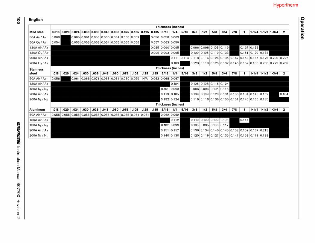
English
Mild steel
Thickness (inches)
0.018 0.020 0.024 0.030 0.036 0.048 0.060 0.075 0.105 0.125 0.135 3/16 1/4 5/16 3/8 1/2 5/8 3/4 7/8 1 1-1/4 1-1/2 1-3/4 2
50A Air / Air 0.069 0.065 0.061 0.056 0.060 0.064 0.063 0.059 0.056 0.058 0.063
50A O2 / Air 0.054 0.053 0.053 0.053 0.054 0.055 0.055 0.056 0.057 0.063 0.059
130A Air / Air 0.085 0.090 0.095 0.096 0.098 0.108 0.119 0.137 0.156
130A O2 / Air 0.092 0.093 0.095 0.100 0.105 0.119 0.133 0.151 0.170 0.188
200A Air / Air 0.111 0.114 0.118 0.116 0.126 0.135 0.147 0.158 0.165 0.172 0.200 0.227
200A O2 / Air 0.109 0.123 0.119 0.125 0.132 0.145 0.157 0.180 0.203 0.229 0.255
Stainless steel
Thickness (inches)
.018 .020 .024 .030 .036 .048 .060 .075 .105 .125 .135 3/16 1/4 5/16 3/8 1/2 5/8 3/4 7/8 1 1-1/4 1-1/2 1-3/4 2
50A Air / Air 0.056 0.061 0.066 0.071 0.066 0.061 0.060 0.059 N/A 0.063 0.068 0.067
130A Air / Air 0.104 0.106 0.108 0.116 0.124
130A N2 / N2 0.101 0.093 0.096 0.094 0.105 0.116
200A Air / Air 0.119 0.105 0.109 0.109 0.120 0.131 0.135 0.134 0.143 0.152 0.184
200A N2 / N2 0.132 0.124 0.116 0.116 0.136 0.156 0.151 0.145 0.165 0.185
Aluminum
Thickness (inches)
.018 .020 .024 .030 .036 .048 .060 .075 .105 .125 .135 3/16 1/4 5/16 3/8 1/2 5/8 3/4 7/8 1 1-1/4 1-1/2 1-3/4 2
50A Air / Air 0.055 0.055 0.055 0.055 0.055 0.055 0.055 0.055 0.061 0.061 0.062 0.062
130A Air / Air 0.112 0.110 0.109 0.109 0.108 0.114
130A N2 / N2 0.107 0.099 0.105 0.095 0.106 0.117
200A Air / Air 0.151 0.157 0.136 0.134 0.140 0.145 0.152 0.159 0.167 0.213
200A N2 / N2 0.140 0.130 0.120 0.119 0.127 0.135 0.147 0.159 0.179 0.199
Hypertherm
MAXPRO200 Instruction Manual 807700 Revision 2 101
Operation
Cut chartsThe following cut charts for the MAXPRO200 show the consumable parts, cutting speeds, and the gas and torch settings required for each process, allowing for differences in the lead length. While you can use these parameters for cutting with both mechanized and handheld torches, the consumable part numbers listed with each cut chart are specific to mechanized torches. Refer to Hand held cutting and gouging consumable selection on page 87 for the consumables to use for handheld torches for each process.
The cut chart values in this document are recommended to provide high quality cuts with minimal dross. Because of differences between installations and material composition, adjustments may be required to obtain desired results.
Hypertherm

102 MAXPRO200 Instruction Manual 807700 Revision 2
Operation
Metric
Mild steelAir Plasma / Air Shield
50 A Cutting
Flow rates – lpm/scfh
Air (Plasma) Air (Shield)
12/25 103/218
Note: Gas pressure values are set automatically by the system when the process is chosen. The arc voltage settings in these cut charts were measured with a lead length of 30.5 meters (100 feet). Adjustments to arc voltage settings may be needed for shorter lead lengths.
Plasma Cutflow Shield Cutflow Material Thickness
Arc Voltage
Cut Height
Cutting Speed Pierce Height Pierce
Delay
7.6 m Lead
15.3 m Lead
22 9 m Lead
30.5 m Lead
7.6 m Lead
15.3 m Lead
22.9 m Lead
30.5 m Lead mm Volts mm mm/min mm Factor % Seconds
62 63 63 63 39 42 45 47
0.5 112 1.5 9400 3.0 200 0.00.8 111 1.5 8510 3.0 200 0.01.0 111 1.5 8050 3.0 200 0.11.2 110 1.8 7625 3.6 200 0.11.5 110 1.8 7370 3.6 200 0.12.0 110 1.8 6735 3.6 200 0.12.5 111 2.0 5080 4.0 200 0.23.0 111 2.0 3760 4.0 200 0.34.0 113 2.3 2415 4.6 200 0.46.0 118 2.5 1600 5.0 200 0.5
English
Plasma Cutflow Shield Cutflow Material Thickness
Arc Voltage
Cut Height
Cutting Speed Pierce Height Pierce
Delay
25 ft Lead
50 ft Lead
75 ft Lead
100 ft Lead
25 ft Lead
50 ft Lead
75 ft Lead
100 ft Lead in Volts in ipm in Factor % Seconds
62 63 63 63 39 42 45 47
0.018 112 0.06 375 0.12 200 0.00.024 112 0.06 350 0.12 200 0.00.030 111 0.06 340 0.12 200 0.00.036 111 0.06 325 0.12 200 0.10.048 110 0.07 300 0.14 200 0.10.060 110 0.07 290 0.14 200 0.10.075 110 0.07 275 0.14 200 0.10.105 111 0.08 180 0.16 200 0.20.135 111 0.08 110 0.16 200 0.33/16 116 0.09 75 0.18 200 0.41/4 118 0.10 60 0.20 200 0.5
*with IHS tab / **without IHS tab
220532 220890 220529 220528220936* / 220935**
Hypertherm

MAXPRO200 Instruction Manual 807700 Revision 2 103
Operation
Note: Gas pressure values are set automatically by the system when the process is chosen. The arc voltage settings in these cut charts were measured with a lead length of 30.5 meters (100 feet). Adjustments to arc voltage settings may be needed for shorter lead length.
Metric
Plasma Cutflow Shield Cutflow Material Thickness
Arc Voltage
Cut Height
Cutting Speed Pierce Height Pierce
Delay
7.6 m Lead
15.3 m Lead
22 9 m Lead
30.5 m Lead
7.6 m Lead
15.3 m Lead
22.9 m Lead
30.5 m Lead mm Volts mm mm/min mm Factor % Seconds
68 68 69 69 25 27 29 31
0.5 98 1.5 7550 3.0 200 0.00.8 96 1.5 7050 3.0 200 0.01.0 90 1.5 6775 3.0 200 0.11.2 94 1.5 6600 3.6 200 0.11.5 99 1.5 6150 3.6 200 0.12.0 99 1.5 5400 3.6 200 0.12.5 99 1.8 4300 4.0 200 0.23.0 99 1.8 3650 4.0 200 0.34.0 101 2.0 2800 4.6 200 0.46.0 103 2.5 1750 5.0 200 0.5
English
Plasma Cutflow Shield Cutflow Material Thickness
Arc Voltage
Cut Height
Cutting Speed Pierce Height Pierce
Delay
25 ft Lead
50 ft Lead
75 ft Lead
100 ft Lead
25 ft Lead
50 ft Lead
75 ft Lead
100 ft Lead in Volts in ipm in Factor % Seconds
68 68 69 69 25 27 29 31
0.018 98 0.06 300 0.12 200 0.00.024 98 0.06 290 0.12 200 0.00.030 98 0.06 280 0.12 200 0.00.036 89 0.06 270 0.12 200 0.10.048 94 0.06 260 0.12 200 0.10.060 99 0.06 240 0.12 200 0.10.075 99 0.06 220 0.12 200 0.10.105 99 0.07 160 0.14 200 0.20.135 99 0.07 130 0.14 200 0.33/16 103 0.09 85 0.15 150 0.41/4 103 0.10 65 0.15 150 0.5
*with IHS tab / **without IHS tab
Mild steelO2 Plasma / Air Shield
50 A Cutting
220532 220891 220529 220528220936* / 220935**
Flow rates – lpm/scfhO2 (Plasma) Air (Shield)
12/25 73/155
Hypertherm

104 MAXPRO200 Instruction Manual 807700 Revision 2
Operation
Note: Gas pressure values are set automatically by the system when the process is chosen. The arc voltage settings in these cut charts were measured with a lead length of 30.5 meters (100 feet). Adjustments to arc voltage settings may be needed for shorter lead lengths.
Metric
Plasma Cutflow Shield Cutflow Material Thickness
Arc Voltage
Cut Height
Cutting Speed Pierce Height Pierce
Delay
7.6 m Lead
15.3 m Lead
22 9 m Lead
30.5 m Lead
7.6 m Lead
15.3 m Lead
22.9 m Lead
30.5 m Lead mm Volts mm mm/min mm Factor % Seconds
68 69 70 71 22 24 26 28
3.0 149 3.0 5350 6.0 200 0.14.0 147 3.0 4630 6.0 200 0.26.0 142 2.4 3865 7.2 300 0.310.0 152 4.1 2445 8.2 200 0.512.0 154 4.1 2045 8.2 200 0.515.0 155 4.4 1445 8.8 200 0.820.0 158 4.6 815 9.6 210 1.225.0 166 4.6 415
Edge start32.0 178 5.1 250
English
Plasma Cutflow Shield Cutflow Material Thickness
Arc Voltage
Cut Height
Cutting Speed Pierce Height Pierce
Delay
25 ft Lead
50 ft Lead
75 ft Lead
100 ft Lead
25 ft Lead
50 ft Lead
75 ft Lead
100 ft Lead in Volts in ipm in Factor % Seconds
68 69 70 71 22 24 26 28
0.135 149 0.12 220 0.24 200 0.13/16 145 0.12 160 0.24 200 0.21/4 141 0.10 150 0.28 300 0.33/8 151 0.16 100 0.32 200 0.51/2 154 0.16 75 0.32 200 0.55/8 155 0.18 50 0.36 200 0.83/4 156 0.18 35 0.38 210 1.21 167 0.18 15
Edge start1-1/4 178 0.20 10
*with IHS tab / **without IHS tab
Mild steelAir Plasma / Air Shield
130 A Cutting
220536 220892 220488 220487220936* / 220935**
Flow rates – lpm/scfhAir (Plasma) Air (Shield)
33/70 68/145
Hypertherm

MAXPRO200 Instruction Manual 807700 Revision 2 105
Operation
Note: Gas pressure values are set automatically by the system when the process is chosen. The arc voltage settings in these cut charts were measured with a lead length of 30.5 meters (100 feet). Adjustments to arc voltage settings may be needed for shorter lead lengths.
Metric
Plasma Cutflow Shield Cutflow Material Thickness
Arc Voltage
Cut Height
Cutting Speed Pierce Height Pierce
Delay
7.6 m Lead
15.3 m Lead
22 9 m Lead
30.5 m Lead
7.6 m Lead
15.3 m Lead
22.9 m Lead
30.5 m Lead mm Volts mm mm/min mm Factor % Seconds
62 62 64 64 30 32 35 37
3.0 130 2.6 5900 5.2 200 0.14.0 131 2.7 5325 5.4 200 0.26.0 134 2.8 3925 5.6 200 0.310.0 136 3.0 2680 6.0 200 0.412.0 138 3.0 2200 6.0 200 0.515.0 140 3.6 1665 7.2 200 0.720.0 145 3.9 1195 7.8 200 1.025.0 151 4.1 685
Edge start32.0 158 4.6 51538.0 163 4.6 310
English
Plasma Cutflow Shield Cutflow Material Thickness
Arc Voltage
Cut Height
Cutting Speed Pierce Height Pierce
Delay
25 ft Lead
50 ft Lead
75 ft Lead
100 ft Lead
25 ft Lead
50 ft Lead
75 ft Lead
100 ft Lead in Volts in ipm in Factor % Seconds
62 62 64 64 30 32 35 37
0.135 130 0.10 240 0.20 200 0.13/16 132 0.11 190 0.22 200 0.21/4 134 0.11 150 0.22 200 0.33/8 136 0.12 110 0.24 200 0.31/2 138 0.12 80 0.24 200 0.55/8 141 0.15 60 0.30 200 0.73/4 144 0.15 50 0.30 200 1.01 151 0.16 25
Edge start1-1/4 158 0.18 201-1/2 163 0.18 12
*with IHS tab / **without IHS tab
Mild steelO2 Plasma / Air Shield
130 A Cutting
220491 220893 220488 220487220936* / 220935**
Flow rates – lpm/scfhO2 (Plasma) Air (Shield)
20/42 86/183
Hypertherm

106 MAXPRO200 Instruction Manual 807700 Revision 2
Operation
Note: Gas pressure values are set automatically by the system when the process is chosen. The arc voltage settings in these cut charts were measured with a lead length of 30.5 meters (100 feet). Adjustments to arc voltage settings may be needed for shorter lead lengths.
Metric
Plasma Cutflow Shield Cutflow Material Thickness
Arc Voltage
Cut Height
Cutting Speed Pierce Height Pierce
Delay
7.6 m Lead
15.3 m Lead
22 9 m Lead
30.5 m Lead
7.6 m Lead
15.3 m Lead
22.9 m Lead
30.5 m Lead mm Volts mm mm/min mm Factor % Seconds
52 54 55 56 48 50 54 58
6.0 147 1.0 4885 3.0 300 0.38.0 148 1.3 4515 3.9 300 0.510.0 151 3.0 3556 5.2 200 0.812.0 153 3.0 2794 6.0 200 0.915.0 158 4.3 2265 8.6 200 1.020.0 165 4.8 1415 9.6 200 1.425.0 172 6.4 940 12.8 200 1.732.0 176 6.4 630 12.8 200 2.338.0 179 6.4 510
Edge start44.0 189 6.4 32050.0 199 6.4 215
English
Plasma Cutflow Shield Cutflow Material Thickness
Arc Voltage
Cut Height
Cutting Speed Pierce Height Pierce
Delay
25 ft Lead
50 ft Lead
75 ft Lead
100 ft Lead
25 ft Lead
50 ft Lead
75 ft Lead
100 ft Lead in Volts in ipm in Factor % Seconds
52 54 55 56 48 50 54 58
1/4 145 0.04 190 0.12 300 0.35/16 148 0.05 180 0.15 300 0.53/8 151 0.10 140 0.20 200 0.81/2 154 0.13 110 0.25 200 0.95/8 159 0.19 85 0.38 200 1.03/4 164 0.19 60 0.38 200 1.27/8 169 0.19 50 0.38 200 1.41 173 0.25 35 0.45 180 1.7
1-1/4 176 0.25 25 0.45 180 2.31-1/2 179 0.25 20
Edge start1-3/4 190 0.25 122 200 0.25 8
*with IHS tab / **without IHS tab
Mild steelAir Plasma / Air Shield
200 A Cutting
420045 420044 220488 220937220936* / 220935**
Flow rates – lpm/scfhAir (Plasma) Air (Shield)
32/68 123/260
Hypertherm
MAXPRO200 Instruction Manual 807700 Revision 2 107
Operation
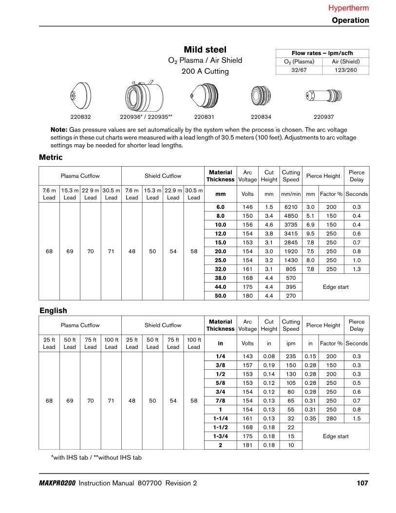
Note: Gas pressure values are set automatically by the system when the process is chosen. The arc voltage settings in these cut charts were measured with a lead length of 30.5 meters (100 feet). Adjustments to arc voltage settings may be needed for shorter lead lengths.
Metric
Plasma Cutflow Shield Cutflow Material Thickness
Arc Voltage
Cut Height
Cutting Speed Pierce Height Pierce
Delay
7.6 m Lead
15.3 m Lead
22 9 m Lead
30.5 m Lead
7.6 m Lead
15.3 m Lead
22.9 m Lead
30.5 m Lead mm Volts mm mm/min mm Factor % Seconds
68 69 70 71 48 50 54 58
6.0 146 1.5 6210 3.0 200 0.38.0 150 3.4 4850 5.1 150 0.410.0 156 4.6 3735 6.9 150 0.412.0 154 3.8 3415 9.5 250 0.615.0 153 3.1 2845 7.8 250 0.720.0 154 3.0 1920 7.5 250 0.825.0 154 3.2 1430 8.0 250 1.032.0 161 3.1 805 7.8 250 1.338.0 168 4.4 570
Edge start44.0 175 4.4 39550.0 180 4.4 270
English
Plasma Cutflow Shield Cutflow Material Thickness
Arc Voltage
Cut Height
Cutting Speed Pierce Height Pierce
Delay
25 ft Lead
50 ft Lead
75 ft Lead
100 ft Lead
25 ft Lead
50 ft Lead
75 ft Lead
100 ft Lead in Volts in ipm in Factor % Seconds
68 69 70 71 48 50 54 58
1/4 143 0.08 235 0.15 200 0.33/8 157 0.19 150 0.28 150 0.31/2 153 0.14 130 0.28 200 0.35/8 153 0.12 105 0.28 250 0.53/4 154 0.12 80 0.28 250 0.67/8 154 0.13 65 0.31 250 0.71 154 0.13 55 0.31 250 0.8
1-1/4 161 0.13 32 0.35 280 1.51-1/2 168 0.18 22
Edge start1-3/4 175 0.18 152 181 0.18 10
*with IHS tab / **without IHS tab
Mild steelO2 Plasma / Air Shield
200 A Cutting
220832 220831 220834 220937220936* / 220935**
Flow rates – lpm/scfhO2 (Plasma) Air (Shield)
32/67 123/260
Hypertherm

108 MAXPRO200 Instruction Manual 807700 Revision 2
Operation
Note: Gas pressure values are set automatically by the system when the process is chosen. The arc voltage settings in these cut charts were measured with a lead length of 30.5 meters (100 feet). Adjustments to arc voltage settings may be needed for shorter lead lengths.
Metric
Plasma Cutflow Shield Cutflow Material Thickness
Arc Voltage
Cut Height
Cutting Speed Pierce Height Pierce
Delay
7.6 m Lead
15.3 m Lead
22 9 m Lead
30.5 m Lead
7.6 m Lead
15.3 m Lead
22.9 m Lead
30.5 m Lead mm Volts mm mm/min mm Factor % Seconds
62 63 63 63 39 42 45 47
0.5 101 1.5 8000 3.0 200 0.00.8 102 1.6 7750 3.2 200 0.01.0 102 1.8 7115 3.6 200 0.11.2 103 1.8 6350 3.6 200 0.11.5 106 1.8 5335 3.6 200 0.12.0 108 2.0 4200 4.0 200 0.12.5 111 2.0 3300 4.0 200 0.23.0 112 2.0 2800 4.0 200 0.34.0 116 2.2 2300 4.4 200 0.46.0 123 2.5 1400 5.0 200 0.5
English
Plasma Cutflow Shield Cutflow Material Thickness
Arc Voltage
Cut Height
Cutting Speed Pierce Height Pierce
Delay
25 ft Lead
50 ft Lead
75 ft Lead
100 ft Lead
25 ft Lead
50 ft Lead
75 ft Lead
100 ft Lead in Volts in ipm in Factor % Seconds
62 63 63 63 39 42 45 47
0.018 101 0.06 300 0.12 200 0.00.024 101 0.06 275 0.12 200 0.00.030 102 0.06 265 0.12 200 0.00.036 102 0.06 250 0.12 200 0.10.048 103 0.07 225 0.14 200 0.10.060 106 0.07 190 0.14 200 0.10.075 107 0.07 165 0.14 200 0.10.105 112 0.08 125 0.16 200 0.20.135 113 0.08 85 0.16 200 0.33/16 119 0.09 55 0.18 200 0.41/4 124 0.10 45 0.20 200 0.5
*with IHS tab / **without IHS tab
Stainless steelAir Plasma / Air Shield
50 A Cutting
220532 220890 220529 220528220936* / 220935**
Flow rates – lpm/scfhAir (Plasma) Air (Shield)
12/25 103/218
Hypertherm

MAXPRO200 Instruction Manual 807700 Revision 2 109
Operation
Note: Gas pressure values are set automatically by the system when the process is chosen. The arc voltage settings in these cut charts were measured with a lead length of 30.5 meters (100 feet). Adjustments to arc voltage settings may be needed for shorter lead lengths.
Metric
Plasma Cutflow Shield Cutflow Material Thickness
Arc Voltage
Cut Height
Cutting Speed Pierce Height Pierce
Delay
7.6 m Lead
15.3 m Lead
22 9 m Lead
30.5 m Lead
7.6 m Lead
15.3 m Lead
22.9 m Lead
30.5 m Lead mm Volts mm mm/min mm Factor % Seconds
68 69 70 71 22 24 26 28
6.0 147 3.5 2625 7.0 200 0.310.0 153 4.1 1700 8.2 200 0.512.0 155 4.1 1380 8.2 200 0.815.0 160 4.4 900
Edge start20.0 170 4.6 430
English
Plasma Cutflow Shield Cutflow Material Thickness
Arc Voltage
Cut Height
Cutting Speed Pierce Height Pierce
Delay
25 ft Lead
50 ft Lead
75 ft Lead
100 ft Lead
25 ft Lead
50 ft Lead
75 ft Lead
100 ft Lead in Volts in ipm in Factor % Seconds
68 69 70 71 22 24 26 28
1/4 148 0.14 100 0.28 200 0.33/8 152 0.16 70 0.32 200 0.51/2 156 0.16 50 0.32 200 0.85/8 162 0.18 30
Edge start3/4 168 0.18 20
*with IHS tab / **without IHS tab
Stainless steelAir Plasma / Air Shield
130 A Cutting
220536 220892 220488 220487220936* / 220935**
Flow rates – lpm/scfhAir (Plasma) Air (Shield)
33/70 69/145
Hypertherm

110 MAXPRO200 Instruction Manual 807700 Revision 2
Operation
Note: Gas pressure values are set automatically by the system when the process is chosen. The arc voltage settings in these cut charts were measured with a lead length of 30.5 meters (100 feet). Adjustments to arc voltage settings may be needed for shorter lead lengths.
Metric
Plasma Cutflow Shield Cutflow Material Thickness
Arc Voltage
Cut Height
Cutting Speed Pierce Height Pierce
Delay
7.6 m Lead
15.3 m Lead
22 9 m Lead
30.5 m Lead
7.6 m Lead
15.3 m Lead
22.9 m Lead
30.5 m Lead mm Volts mm mm/min mm Factor % Seconds
68 69 70 71 36 39 42 44
5.0 148 3.0 3140 6.1 200 0.36.0 151 3.0 2980 6.1 200 0.310.0 152 3.3 1830 6.6 200 0.512.0 154 3.3 1510 6.6 200 0.815.0 158 3.6 1120
Edge start20.0 166 3.8 470
English
Plasma Cutflow Shield Cutflow Material Thickness
Arc Voltage
Cut Height
Cutting Speed Pierce Height Pierce
Delay
25 ft Lead
50 ft Lead
75 ft Lead
100 ft Lead
25 ft Lead
50 ft Lead
75 ft Lead
100 ft Lead in Volts in ipm in Factor % Seconds
68 69 70 71 36 39 42 44
3/16 149 0.12 125 0.24 200 0.31/4 151 0.12 115 0.24 200 0.33/8 152 0.13 75 0.26 200 0.51/2 154 0.13 55 0.26 200 0.85/8 159 0.14 40
Edge start3/4 165 0.15 25
*with IHS tab / **without IHS tab
Stainless steelN2 Plasma / N2 Shield
130 A Cutting
220536 220892 220529 020415220936* / 220935**
Flow rates – lpm/scfhN2 (Plasma) N2 (Shield)
32/68 104/218
Hypertherm
MAXPRO200 Instruction Manual 807700 Revision 2 111
Operation
Note: Gas pressure values are set automatically by the system when the process is chosen. The arc voltage settings in these cut charts were measured with a lead length of 30.5 meters (100 feet). Adjustments to arc voltage settings may be needed for shorter lead lengths.
Metric
Plasma Cutflow Shield Cutflow Material Thickness
Arc Voltage
Cut Height
Cutting Speed Pierce Height Pierce
Delay
7.6 m Lead
15.3 m Lead
22 9 m Lead
30.5 m Lead
7.6 m Lead
15.3 m Lead
22.9 m Lead
30.5 m Lead mm Volts mm mm/min mm Factor % Seconds
52 54 55 56 48 50 54 58
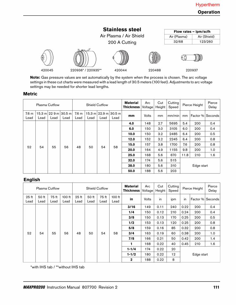
4.0 148 2.7 5695 5.4 200 0.46.0 150 3.0 3105 6.0 200 0.410.0 150 3.2 2485 6.4 200 0.512.0 152 3.2 2245 6.4 200 0.815.0 157 3.8 1700 7.6 200 0.820.0 164 4.9 1155 9.8 200 1.025.0 168 5.6 670 11.8 210 1.632.0 174 5.6 515
Edge start38.0 180 5.6 31050.0 188 5.6 203
English
Plasma Cutflow Shield Cutflow Material Thickness
Arc Voltage
Cut Height
Cutting Speed Pierce Height Pierce
Delay
25 ft Lead
50 ft Lead
75 ft Lead
100 ft Lead
25 ft Lead
50 ft Lead
75 ft Lead
100 ft Lead in Volts in ipm in Factor % Seconds
52 54 55 56 48 50 54 58
3/16 149 0.11 240 0.22 200 0.41/4 150 0.12 210 0.24 200 0.43/8 150 0.13 170 0.25 200 0.51/2 153 0.13 120 0.25 200 0.85/8 159 0.16 85 0.32 200 0.83/4 163 0.19 60 0.38 200 1.07/8 166 0.21 50 0.42 200 1.41 168 0.22 40 0.45 210 1.6
1-1/4 174 0.22 20Edge start1-1/2 180 0.22 12
2 188 0.22 8
*with IHS tab / **without IHS tab
Stainless steelAir Plasma / Air Shield
200 A Cutting
420045 420044 220488 220937220936* / 220935**
Flow rates – lpm/scfhAir (Plasma) Air (Shield)
32/68 123/260
Hypertherm

112 MAXPRO200 Instruction Manual 807700 Revision 2
Operation
Note: Gas pressure values are set automatically by the system when the process is chosen. The arc voltage settings in these cut charts were measured with a lead length of 30.5 meters (100 feet). Adjustments to arc voltage settings may be needed for shorter lead lengths.
Metric
Plasma Cutflow Shield Cutflow Material Thickness
Arc Voltage
Cut Height
Cutting Speed Pierce Height Pierce
Delay
7.6 m Lead
15.3 m Lead
22 9 m Lead
30.5 m Lead
7.6 m Lead
15.3 m Lead
22.9 m Lead
30.5 m Lead mm Volts mm mm/min mm Factor % Seconds
69 70 71 72 42 45 48 51
5.0 156 3.2 4460 6.4 200 0.46.0 159 3.2 3980 6.4 200 0.410.0 160 3.2 2900 6.4 200 0.512.0 162 3.2 2260 6.4 200 0.815.0 165 3.4 1760 7.9 230 0.920.0 172 4.2 1190 10.1 240 1.125.0 185 6.4 790 11.4 180 2.032.0 191 6.4 520
Edge start38.0 197 6.4 310
English
Plasma Cutflow Shield Cutflow Material Thickness
Arc Voltage
Cut Height
Cutting Speed Pierce Height Pierce
Delay
25 ft Lead
50 ft Lead
75 ft Lead
100 ft Lead
25 ft Lead
50 ft Lead
75 ft Lead
100 ft Lead in Volts in ipm in Factor % Seconds
69 70 71 72 42 45 48 51
3/16 159 0.13 180 0.25 200 0.41/4 159 0.13 150 0.25 200 0.43/8 160 0.13 120 0.25 200 0.51/2 163 0.13 80 0.25 200 0.85/8 166 0.14 65 0.32 230 0.93/4 170 0.16 50 0.38 240 1.07/8 178 0.19 40 0.38 200 1.51 186 0.25 30 0.45 180 2.0
1-1/4 191 0.25 21Edge start
1-1/2 197 0.25 12
*with IHS tab / **without IHS tab
Stainless steelN2 Plasma / N2 Shield
200 A Cutting
220936* / 220935**420045 420044 220529 020415
Flow rates – lpm/scfhN2 (Plasma) N2 (Shield)
37/79 107/225
Hypertherm

MAXPRO200 Instruction Manual 807700 Revision 2 113
Operation
Note: Gas pressure values are set automatically by the system when the process is chosen. The arc voltage settings in these cut charts were measured with a lead length of 30.5 meters (100 feet). Adjustments to arc voltage settings may be needed for shorter lead lengths.
Metric
Plasma Cutflow Shield Cutflow Material Thickness
Arc Voltage
Cut Height
Cutting Speed Pierce Height Pierce
Delay
7.6 m Lead
15.3 m Lead
22 9 m Lead
30.5 m Lead
7.6 m Lead
15.3 m Lead
22.9 m Lead
30.5 m Lead mm Volts mm mm/min mm Factor % Seconds
62 63 63 63 39 42 45 47
0.5 112 1.5 8000 3.0 200 0.00.8 113 1.6 7750 3.2 200 0.01.0 114 1.8 7115 3.6 200 0.11.2 114 1.8 6350 3.6 200 0.11.5 115 1.8 5335 3.6 200 0.12.0 120 2.0 4200 4.0 200 0.12.5 123 2.0 3300 4.0 200 0.23.0 124 2.0 2800 4.0 200 0.34.0 125 2.2 2300 4.4 200 0.46.0 130 2.5 1400 5.0 200 0.5
English
Plasma Cutflow Shield Cutflow Material Thickness
Arc Voltage
Cut Height
Cutting Speed Pierce Height Pierce
Delay
25 ft Lead
50 ft Lead
75 ft Lead
100 ft Lead
25 ft Lead
50 ft Lead
75 ft Lead
100 ft Lead in Volts in ipm in Factor % Seconds
62 63 63 63 39 42 45 47
0.018 112 0.06 325 0.12 200 0.00.020 112 0.06 315 0.12 200 0.00.024 112 0.06 305 0.12 200 0.00.030 113 0.06 295 0.12 200 0.10.036 114 0.07 280 0.14 200 0.10.048 114 0.07 230 0.14 200 0.20.060 115 0.07 195 0.14 200 0.20.075 120 0.08 160 0.16 200 0.20.105 123 0.08 120 0.16 200 0.30.125 124 0.08 100 0.16 200 0.33/16 126 0.09 75 0.18 200 0.41/4 131 0.10 50 0.20 200 0.5
*with IHS tab / **without IHS tab
AluminumAir Plasma / Air Shield
50 A Cutting
220532 220890 220529 220528220936* / 220935**
Flow rates – lpm/scfhAir (Plasma) Air (Shield)
12/25 104/218
Hypertherm