hyperiontm split systems - trane.com · gaf/gat/gam _____ 11 performance data cooling ... 2 = 12 5...
TRANSCRIPT

Split Systems Air Conditioning (Ducted Type)3.0 - 5.0 Tons - R410a - 50Hz
HyperionTM Split Systems
SSA-PRC011A-E4
Indoor Units GAF2A0A36S3ASAGAT2A0C48S4ASAGAT2A0C60S5ASAGAM2A0C48S4ASBGAM2A0C60S5ASB
Outdoor Units 4TTB3018AA4TTB3024AA4TTB3030AA4TTB3036AA4TTA3030AD4TTA3036AD4TTA3042AD4TTA3048AD4TTA3060AD


Contents
Features and Benefits _____________________________________________________ 04
Nomenclature ____________________________________________________________ 05
General Data 4TTB __________________________________________________________ 08
4TTA __________________________________________________________ 09 GAF/GAT/GAM __________________________________________________ 11
Performance Data Cooling _________________________________________________ 15
Electrical Data __________________________________________________________ 19
Wiring Diagram _________________________________________________________ 23
Dimensions 4TTB __________________________________________________________ 28 GAF __________________________________________________________ 30 GAT/GAM ______________________________________________________ 32
Mechanical Specifications 4TTB __________________________________________________________ 34 4TTA __________________________________________________________ 35
3

Features and Benefits
Indoor convertible airhandler GAT/GAM• Unique Cabinet Design - Double Wall Foamed and Formed Cabinet System - Water Proof Cabinet Design - R-4.2 Insulating Value (Avg. Insulating Value R-8.2) - Composite Foamed Cabinet Doors - Sweat Eliminating Cabinet Design - Loose Fiber Eliminating Cabinet Design - Smooth Cleanable Cabinet Design - 2% or Less air leakage - Precision Applied Durable Door Seals - Tool-free Fasteners on Blower/Filter Door - Modular Cabinet - Loose Fiber Eliminating Cabinet Design - Smooth Cleanable Cabinet Design - 2% or Less air leakage - Precision Applied Durable Door Seals - Tool-free Fasteners on Blower/Filter Door - Modular Cabinet • Multi-Position Upflow/ Horizontal Left / Horizontal Right• Braze in Refrigerant Connection • Primary/Secondary Condensate Connections • Premarked Conduit Connection Locations• Vortica Blower with Integrated Slide Deck for Easy Removal• Polarized Plug connections on Blower• Control Protection Pocket• Aluminum Coil with Integrated Slide Deck for Easy Removal• Slide in Electric Heaters• Polarized Plug connections for Electric Heater• Labeled Panels and connections• 1-1/4" to 1" And 3/4" to 1/2" Conduit connection on Left, Right and Top• Molded in 1" Standard Filter rail • R-410A Thermal Expansion Valve (TXV)• Convertible to R-22 using optional accessory TXV conversion kit.• Low Voltage Terminal Connection Point• Enhanced Coil Fin Patented• Blow Through Design• PSC 3 Speed Motor on 3.5 & 4 ton models• Constant torque ECM Motor on 5 ton model• Maximum Width of 23.5"• Compact 20.8" depth with doors removed• Integrated Horizontal Drain pans• Single Color• Fused 24V Power• Safety Door Switch
Indoor convertible air handler GAF• Unique Cabinet Design - Double Wall Foamed and Formed Cabinet System - Water Proof Cabinet Design - R-4.2 Insulating Value (Avg. Insulating Value R-8) - Composite Foamed Cabinet Doors - Sweat Eliminating Cabinet Design - Loose Fiber Eliminating Cabinet Design - Smooth Cleanable Cabinet Design - 2% or Less air leakage - Precision Applied Durable Door Seals• Multi-Position Upflow/ Horizontal Left / Horizontal Right• Front Return Option• Braze in Refrigerant Connection • Primary/Secondary Condensate Connections • Vortica Blower with Integrated Slide Deck for Easy Removal• Polarized Plug connections on Blower• Aluminum Coil with Integrated Slide Deck for Easy Removal• Slide in Electric Heaters• Polarized Plug connections for Electric Heater• Labeled Panels and connections• Guide for 1-1/4" to 1" And 3/4" to 1/2" Conduit connection on Top• R-410A Thermal Expansion Valve (TXV)• Convertible to R-22 using optional accessory TXV conversion kit.• Low Voltage Color Coded Wires• Enhanced Coil Fin Patented• Blow Through Design• PSC 3 Speed Motor • Maximum Width of 17.5"• Compact 20.8" depth with doors removed• Integrated Horizontal Drain pans• Single Color• Fused 24V Power
Outdoor unit 4TTB • Scroll compressor• Efficiency up to 13 S E E R• All aluminum SPINE FIN ™ coil• WEATHERGUARD™ fasteners• QUICK-SESS ™ cabinet, service access and refrigerant connections with full coil protection• DURATUFF ™ base, fast complete drain, weatherproof
• COMFORT-R ™ mode approved• Glossy corrosion resistant finish• Internal compressor high/low pressure & temperature protection• Liquidline filter supplied for field installations• Polyslategray cabinet with anthracite gray badge and cap• High pressure control• Low pressure control• Sump Heater/Crankcase Heater• Service valve cover• R-410A refrigerant• S.E.E.T. design testing• 100% line run test• Low ambient cooling to 30°F with AY28X079• Low ambient cooling to 55°F as shipped
Outdoor unit 4TTA • Scroll compressor• Efficiency up to 13 S E E R• All aluminum SPINE FIN ™ coil• WEATHERGUARD™ fasteners• QUICK-SESS ™ cabinet, service access and refrigerant connections with full coil protection• DURATUFF ™ base, fast complete drain, weatherproof
• COMFORT-R ™ mode approved• Glossy corrosion resistant finish• Internal compressor high/low pressure & temperature protection• Liquidline filter supplied for field installations• Polyslate gray cabinet with anthracite gray badge and cap• High pressure control• Low pressure control• Sump Heater/Crankcase Heater• Service valve cover• R-410A refrigerant• S.E.E.T. design testing• 100% line run test• Low ambient cooling to 30°F with AY28X079• Low ambient cooling to 55°F as shipped
4

G A F 2 A 0 B 3 6 M 3 1 S A A
BrandT = BetterG = Good
Product TypeA = Air Handler
Product Tier2 = Good, Entry Level Feature Set4 = Better, Retail Replacement Mid Effy.5 = Better, Entry Level High Effy., Multi-Speed7 = Best, Retail Replacement High Effy., Variable-Speed8 = Best, Retail Ultimate High Effy., Variable-Speed
Major Design Change
Minor Design ChangeUnit Parts Identifier
Airflow Type & CapabilityS = Low Effy PSC, 1-5 - nom. Tonnage (cfm/ton)M = Mid Effy Multi-Speed, 1-5 - nom. Tonnage (cfm/ton)H = High Effy Multi-Speed, 1-5 - nom. Tonnage (cfm/ton)V = High Effy Variable, 1-5 - nom. Tonnage (cfm/ton)
No Descriptor0 = Air Handler / Coil
System Control TypeS = Standard - 24 VACC = CLII 13.8 VDC
Size (Footprint)A = 17.5 x 21.5B = 21.0 x 21.5C = 23.5 x 21.5
Cooling Size: Air Handler or Coil0-9 = AH Coil - 1000 BTU’s (36, 48, 60)
Power Supply220 - 240/1/50
ConvertabilityM = Multi-poise 4-wayF = Upflow Front Return, 3-wayT = 3-way
Air Handler
Refrigerant Type2 = R-224 = R-410A
TRANE
Product TypeW = Split Heat PumpT = Split Cooling
Product FamilyZ = Leadership – Two StageX = LeadershipR = Replacement/RetailB = BasicA = Light Commercial
Family SEER0 = 10 3 = 13 6 = 161 = 11 4 = 14 8 = 182 = 12 5 = 15 9 = 19
Split System Connections 1-6 Tons0 = Brazed
Nominal Capacity in 000s of BTUs
Major Design Modifications
Power Supply
Secondary Function
Minor Design Modifications
Unit Parts Identifier
Outdoor Units4 T T B 3 0 3 6 A A 0 0 0 A A
Refrigerant Type2 = R-224 = R-410A
TRANE
Product TypeW = Split Heat PumpT = Split Cooling
Product FamilyZ = Leadership – Two StageX = LeadershipR = Replacement/RetailB = BasicA = Light Commercial
Family SEER0 = 10 3 = 13 6 = 161 = 11 4 = 14 8 = 182 = 12 5 = 15 9 = 19
Split System Connections 1-6 Tons0 = Brazed
Nominal Capacity in 000s of BTUs
Major Design Modifications
Power SupplyA = 220-240/1/50 H D = 380-415/3/50
Secondary Function
Minor Design Modifications
Unit Parts Identifier
Outdoor Units4 T T A 3 0 3 6 A D 0 0 0 A A
A = 220-240/1/50 H D = 380-415/3/50
Nomenclature
5
A

6
Unique Cabinet DesignFeatures and Benefits GAF
5 Conduit Connection Location
r Integrated Horizontal Drain Pans
e Compact 20.8” Depth with Doors Removed
1 Unique Cabinet Design
2 Precision Durable Door Seals
q Thermal Expansion Valve (TXV)
3 Refrigeration Connections
9 All Aluminum Coil
4 Condensate Connections
w Maximum width is 17.5”
8 VorticaTM Blower and Deck
0 Labeled Panels and Connections
1 Unique Cabinet Design - Double wall foamed cabinet system - Waterproof Cabinet Design - R-4.2 Insulating Value (Avg. Insulating Value R-8) - Composite Foamed Cabinet Doors - Sweat Eliminating Cabinet Design - Loose Fiber Eliminating Design - Smooth Cleanable Cabinet Design - 2% or Less air leakage2 Precision Durable Door Seals3 Brazed Refrigeration Connections4 Primary/Secondary Condensate Connections5 Conduit Connection - Conduit Connection on Top7 PSC 3 Speed Motor8 VorticaTM Blower and Deck - Polarized Plug on Blower
9 All Aluminum Coil - Integrated Slide Deck for Easy Removal - Polarized Plug connections on Coil TXV - Patented Enhanced Coil Fin0 Labeled Panels and Connectionsq R-410A Thermal Expansion Valve (TXV)w Maximum width is 17.5”e Compact 20.8” Depth with Doors Removedr Integrated Horizontal Drain Pans
7 PSC 3 Speed Motor

7
Unique Cabinet Design Features & Benefits GAT/GAM
5 Conduit Connections
e Integrated Horizontal Drain Pans
6 Tool-less Door Fasteners
w Compact 20.8” Depth with Doors Removed
1 Unique Cabinet Design2 Precision Durable
Door Seals
0 Thermal Expansion Valve (TXV)
3 Refrigeration Connections
8 All Aluminum Coil
r Safety Door Switch
4 Condensate Connections
q Maximum width is 23.5”
7 VorticaTM Blower and Deck
9 Labeled Panels and Connections
1 Unique Cabinet Design - Double wall foamed cabinet system - Waterproof Cabinet Design - R-4.2 Insulating Value (Avg Insulating Value R-8.2) - Composite Foamed Cabinet Doors - Sweat Eliminating Cabinet Design - Loose Fiber Eliminating Design - Smooth Cleanable Cabinet Design2 Precision Durable Door Seals3 Refrigeration Connections4 Condensate Connections5 Premarked Conduit Connection Locations - Conduit
Connections on Left, Right, and Top6 Tool-less Door Fasteners7 VorticaTM Blower and Deck - Polarized Plug on Blower
8 All Aluminum Coil - Integrated Slide Deck for Easy Removal - Polarized Plug connections on Coil EEV - Patented Enhanced Coil Fin9 Labeled Panels and Connections0 R-410A Thermal Expansion Valve (TXV)q Maximum width is 23.5”w Compact 20.8” Depth with Doors Removede Integrated Horizontal Drain Pansr Safety Door Switch - Fused 24V Powert Modular Cabinet
8
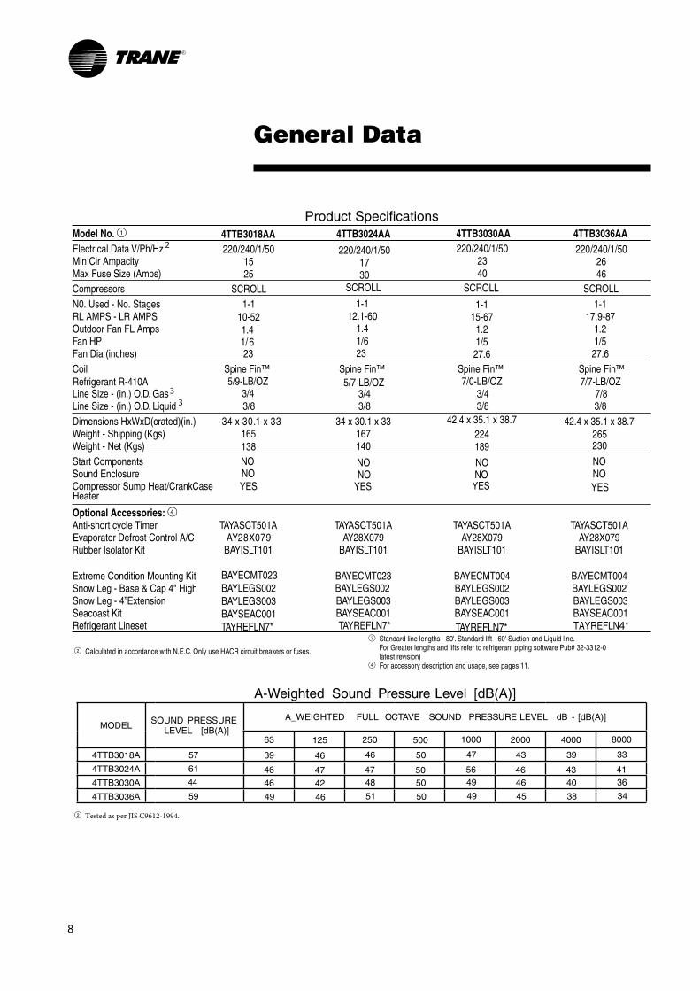
Product Model No. 1Electrical Data V/Ph/Hz Min Cir Ampacity Max Fuse Size (Amps)CompressorsN0. Used - No. Stages 1-1
10-521.4
RL AMPS - LR AMPS Outdoor Fan FL AmpsFan HP 1/ 6Fan Dia (inches) 23 Coil Spine Fin™ Spine Fin™ Spine Fin™ Spine Fin™
5/9-LB/OZ 7/0-LB/OZLine Size - (in.) O.D. GasRefrigerant R-410A
3/4Line Size - (in.) O.D. Liquid 3/8 3/8 3/8Dimensions HxWxD(crated)(in.) 34 x 30.1 x 33 34 x 30.1 x 33 42.4 x 35.1 x 38.7Weight - Shipping (Kgs) 167
140165138
224 Weight - Net (Kgs) 189 230
265
Start Components NOSound Enclosure NOCompressor Sump Heat/CrankCase YES
Optional Accessories: 4Anti-short cycle Timer TAYASCT501ATAYASCT501A TAYASCT501A TAYASCT501A
AY28X079 AY28X079 AY28X079 AY28X079BAYISLT101 BAYISLT101 BAYISLT101 BAYISLT101
BAYECMT023 BAYECMT004 BAYECMT004Extreme Condition Mounting Kit Snow Leg - Base & Cap 4" High BAYLEGS002 BAYLEGS002Snow Leg - 4”Extension BAYLEGS003 BAYLEGS003 BAYLEGS003Seacoast Kit BAYSEAC001 BAYSEAC001 BAYSEAC001Refrigerant Lineset TAYREFLN7* TAYREFLN *
General Data
A-Weighted Sound Pressure Level [dB(A)]
MODEL SOUND PRESSURE LEVEL [dB(A)]
A_WEIGHTED FULL OCTAVE SOUND PRESSURE LEVEL dB - [dB(A)]
4TTB 018
4TTB 024
57
4TTB 030
4TTB 036 9
2 Calculated in accordance with N.E.C. Only use HACR circuit breakers or fuses.
3 Standard line lengths - 80'. Standard lift - 60' Suction and Liquid line.For Greater lengths and lifts refer to refrigerant piping software Pub# 32-3312-0latest revision)
4 For accessory description and usage, see pages 11.
42.4 x 35.1 x 38.7
2 Tested as per JIS C9612-1994.
TAYREFLN7*
33
2
6144
4TTB3018AA 4TTB3024AA 4TTB3030AA 4TTB3036AA
Heater
220/240/1/501525
220/240/1/501730
220/240/1/502340
220/240/1/502646
3/4
NONO
Evaporator Defrost Control A/CRubber Isolator Kit
BAYLEGS002
YES
5/7-LB/OZ3/43/8
7/7-LB/OZ7/8
YES YES
SCROLL SCROLL SCROLL SCROLL1-1
12.1-601.41/623
1-115-67
1.21/527.6
1-117.9-87
1.21/527.6
NONO
NONO
63 125 250 500 1000 2000
46 50 47 4339 46
46 47 47 50 56 46 48 50 49 4646 42
51 50 49 4549 46
4000 8000
39 33
43 41 40 36
38 34
BAYECMT023BAYLEGS002BAYLEGS003BAYSEAC001TAYREFLN7*

9
General Data
Product
4TTA3036AD4TTA3030AD 4TTA3042AD 4TTA3048AD380-415/3/50380-415/3/50
915
6.1 - 38 6.7 - 43 6.9 - 52 7.6 - 51.5
1119
380-415/3/50 380-415/3/501221
1221
1-1 1-1 1-1 1-1
0.7 0.7 0.7 0.71-1/6 1-1/6 1-1/6 1-1/6
27.6 - 1
7/7 LB/OZ 8/5 LB/OZ 8/4 LB/OZ 9/8 LB/OZ
27.6 - 1 27.6 - 1 27.6 - 1Spine Fin™ Spine Fin™ Spine Fin™ Spine Fin™
7/8 7/8 7/83/43/8 3/8 3/8 3/8
42.4 x 35.1 x 38.7 42.4 x 35.1 x 38.7 51 x 35.1 x 38.7 254
219217182
277 240 255
292
TAYASCT501ATAYASCT501A TAYASCT501A TAYASCT501AAY28X079 AY28X079 AY28X079 AY28X079BAYISLT101 BAYISLT101 BAYISLT101 BAYISLT101
BAYECMT023 BAYECMT004 BAYECMT004BAYLEGS002 BAYLEGS002
BAYLEGS003 BAYLEGS003 BAYLEGS003BAYSEAC001 BAYSEAC001 BAYSEAC001TAYREFLN4* TAYREFLN4 *
A-Weighted Sound Pressure Level [dB(A)]
MODEL SOUND PRESSURE LEVEL [dB(A)]
A_WEIGHTED FULL OCTAVE SOUND PRESSURE LEVEL dB - [dB(A)]
63 125 250 500 1000 200 4000
4TTA3030AD
4TTA3036AD
60 51 42 52 50 54 43 38 3352 49 46
5251 52 48 46 41
55 47 52 52 46 40 364926
42 51 52 51 48 424TTB3042AD
4TTA3048AD 6559
2 Calculated in accordance with N.E.C. Only use HACR circuit breakers or fuses.
3 Standard line lengths - 80'. Standard lift - 60' Suction and Liquid line.For Greater lengths and lifts refer to refrigerant piping software Pub# 32-3312-0latest revision)
4 For accessory description and usage, see pages 11.
46.4 x 35.1 x 38.7
2 Tested as per JIS C9612-1994.
TAYREFLN4*
6170
SCROLL SCROLL SCROLL SCROLL
NONOYES
NONOYES
NONOYES
NONOYES
Model No. 1Electrical Data V/Ph/HzMin Cir Ampacity Max Fuse Size (Amps)CompressorsN0. Used - No. StagesRL AMPS - LR AMPS Outdoor Fan FL AmpsFan HPFan Dia (inches)Coil
Line Size - (in.) O.D. GasRefrigerant R-410A
Line Size - (in.) O.D. LiquidDimensions HxWxD(crated)(in.)Weight - Shipping (Lbs)Weight - Net (Lbs)Start ComponentsSound EnclosureCompressor Sump Heat/CrankCase
Optional Accessories: Anti-short cycle Timer
Extreme Condition Mounting Kit Snow Leg - Base & Cap 4" High Snow Leg - 4”ExtensionSeacoast KitRefrigerant Lineset
33
2
Heater
Evaporator Defrost Control A/CRubber Isolator Kit
4TTA3060AD
8.9 - 67.1
380-415/3/501425
1-1
0.71-1/6
9/14 LB/OZ
27.6 - 1Spine Fin™
7/83/8
51 x 35.1 x 38.7
260297
TAYASCT501AAY28X079
BAYISLT101
BAYECMT004BAYLEGS002BAYLEGS003BAYSEAC001TAYREFLN4 *
SCROLL
NONOYES
BAYLEGS002
4TTA3060AD 31 39 47 48 46 444935
BAYECMT023BAYLEGS002 BAYLEGS003BAYSEAC001TAYREFLN7*
8000

10
General Data 4TTA/4TTB
AHRI Standard Capacity Rating Conditions
AHRI STANDARD 210/240 RATING CONDITIONS —(A) Cooling 80°F DB, 67°F WB air entering indoor coil,95°F DB air entering outdoor coil.
Accessory Description and Usage
Anti-Short Cycle Timer - Solid state timing device that prevents compressor recycling until 5 minutes have elapsed after satisfying call or power interruptions. Use in area with questionable power delivery, commercial applications, long lineset, etc.
Evaporator Defrost Control — SPST Temperature actuated switch that cycles the condeser off as indoor coil reaches freeze-up conditions. Used for low ambient cooling to 30°F with TXV. Rubber Isolators — 5 large rubber donuts to isolatecondensing unit from transmitting energy into mounting frameor pad. Use on any application where sound transmission needs to be minimized.
Extreme Condition Mount Kit — Bracket kits to securelymount condensing unit to a frame or pad without removing any panels. Use in areas with high winds, or on commercial roof tops, etc.

General Data GAF/GAT/GAM
1 3/4" Male Plastic Pipe (Ref.: ASTM 1785-76)2 Constant torque Motor3 R-22 requires TXV change. Use R-22 TXV conversion kit BAYATXV1836A.4 R-22 requires TXV change. Use R-22 TXV conversion kit BAYATXV4248A.5 R-22 requires TXV change. Use R-22 TXV conversion kit BAYATXV6060A.
PRODUCT SPECIFICATIONS
MODEL
RATED VOLTS/PH/HZ. RATINGS INDOOR COIL — Type Rows — F.P.I. Face Area (sq. ft.) Tube Size (in.) Refrigerant Control Drain Conn. Size (in.) 1 DUCT CONNECTIONS INDOOR FAN — Type Diameter-Width (In.) No. Used Drive - No. Speeds CFM vs. in. w.g. No. Motors — H.P. Motor Speed RPM Volts/Ph/Hz F.L. Amps - L.R. Amps FILTERFilter Furnished? Type Recommended No.-Size-Thickness REFRIGERANT Ref. Line Connections Coupling or Conn. Size — in. Gas Coupling or Conn. Size — in. Liq. DIMENSIONS Crated (In.) Uncrated WEIGHTShipping (Lbs.) / Net (Lbs.)
GAT2A0C48S4ASA
220-240/1/50See O.D. Specifications
Plate Fin3 - 145.503/8TXV
3/4 NPTSee Outline Drawing
Centrifugal11 X 10
1Direct - 3
See Fan Performance Table1 - 1/21075
220-240/1/503.1 - 5.5
NoThrowaway
1 - 20 X 22 - 1 in.R-410A 4
Brazed7/83/8
H x W x D58 x 25.5 x 24.5
56.9 x 23.5 x 21.8
155/143
GAT2A0C60S5ASA
220-240/1/50See O.D. Specifications
Plate Fin4 - 145.503/8TXV
3/4 NPTSee Outline Drawing
Centrifugal11 X 10
1Direct - 5 2
See Fan Performance Table1 - 11050
220-240/1/507.6 - n/a
NoThrowaway
1 - 20 X 22 - 1 in.R-410A 5
Brazed7/83/8
H x W x D62.8 x 25.5 x 24.561.7 x 23.5 x 21.8
171/159
GAF2A0A36S3ASA
220-240/1/50See O.D. Specifications
Plate Fin3 - 143.213/8TXV
3/4 NPTSee Outline Drawing
Centrifugal11 X 8
1Direct - 3
See Fan Performance Table1 - 1/21075
220-240/1/502.4 - 3.8
NoThrowaway
1 - 16 X 20 - 1 in.R-410A 3
Brazed3/43/8
H x W x D40.5 x 20 x 24.5
39.5 x 17.5 x 21.8
122/112
GAM2A0C48S4ASB GAM2A0C60S5ASB-
11

12
Performance Data GAF
GAF2A0A36 AIRFLOW PERFORMANCE TABLE
Note: Heating and cooling speeds are the same, factory set at Speed Tap #2.
AIRFLOW PERFORMANCE
GAF2A0A36S3ASA
EXTERNAL STATIC (in w.g)
Speed Taps - 220 VOLTS (50Hz)
3 2 † 1
0 1040 1010 983
0.1 1024 998 975
0.2 978 955 927
0.3 925 900 880
0.4 869 845 819
0.5 808 780 757
0.6 734 715 692
0.7 651 625 593
0.8 545 520 498
0.9 439 415 395
1.0 247 241 224
NOTES:1. Values are with wet coil and without filters.2. Contact your particular filter manufacturer for pressure drop data3. † Factory Setting

Performance Data GAT/GAM
13
GAT2A0C48/GAM2A0C48 AIRFLOW PERFORMANCE TABLE
Note: Heating and cooling speeds are the same, factory set at Speed Tap #2.
AIRFLOW PERFORMANCE
GAT2A0C48S4ASA/GAM2A0C48S4ASBA
EXTERNAL STATIC (in w.g)
AIRFLOW (CFM)
Speed Taps - 220 VOLTS (50Hz)
3 2 † 1
0 1897 1815 1728
0.1 1827 1757 1676
0.2 1756 1687 1615
0.3 1682 1617 1552
0.4 1568 1532 1475
0.5 1476 1441 1390
0.6 1379 1340 1291
0.7 1258 1220 1150
0.8 1090 1050 984
0.9 915 891 783
1 682
NOTES:1. Values are with wet coil and without filters.2. Contact your particular filter manufacturer for pressure drop data.3. † Factory Setting

14
Performance Data GAT/GAM
GAT2A0C60/GAM2A0C60 AIRFLOW PERFORMANCE TABLE
AIRFLOW PERFORMANCE
GAT2A0C60S5ASA/GAM2A0C60S5ASB
EXTERNAL STATIC (in w.g)
AIRFLOW (CFM)
Speed Taps - 220 VOLTS (50Hz)
5 4 † 3 2 1
0 2161 1925 1885 1673 1624
0.1 2140 1903 1842 1635 1578
0.2 2110 1871 1807 1593 1540
0.3 2073 1833 1771 1552 1502
0.4 2023 1805 1728 1513 1457
0.5 1963 1766 1691 1468 1417
0.6 1900 1725 1650 1433 1373
0.7 1829 1688 1612 1397 1332
0.8 1742 1633 1572 1354 1290
0.9 1648 1579 1530 1314 1245
1.0 1547 1528 1493 1274 1206
NOTES:1. Values are with wet coil and without filters.2. Contact your particular filter manufacturer for pressure drop data. 3. † Factory Setting
Note: Heating and cooling speeds are the same, factory set at Speed Tap #4 for the CTM motor.

Performance DataCooling
4TTB3030AA WITH GAF2A0A36S3ASAA AT 974 CFM ** NET CAPACITY IN BTU/H X 1000
VALUES AT ARI RATING CONDITIONSNET CAPACITY= 29,200 BTUHAIRFLOW = 974 CFMCOMPRESSOR POWER = 1812 WATTSI.D. FAN POWER = 336 WATTSO.D. FAN POWER = 182 WATTS
E.E.R. = 12.5 BTUH/WCOP = 3.66
CORRECTION FACTORS - OTHER AIRFLOWS(Multiply or Add as indicated)AIRFLOW 900 1050TOTALCAP. x 0.98 x 1.02SENS. CAP.COMPRESSOR KW
x 0.93x 0.99 x 1.01
x 1.07
All temperatures in Degree F
*** Performance at selected design conditions
* Dry coil condition (Total Capacity = Sensible Capacity)
Total capacity, compressor kW and app. dew point valid only for wetcoil
Rated with 25 Feet 3/4 suction 3/8 liquid lines
Compressor Watts = 2,463 @ 118.4F
4TTB3036AA WITH GAF2A0A36S3ASAA AT 974 CFM ** NET CAPACITY IN BTU/H X 1000
VALUES AT ARI RATING CONDITIONSNET CAPACITY= 32,920 BTUHAIRFLOW = 974 CFMCOMPRESSOR POWER = 2257 WATTSI.D. FAN POWER = 377 WATTSO.D. FAN POWER = 182 WATTS
E.E.R. = 11.7 BTUH/WCOP = 3.43
CORRECTION FACTORS - OTHER AIRFLOWS(Multiply or Add as indicated)AIRFLOW 900 1050TOTALCAP. x 0.98 x 1.02SENS. CAP.COMPRESSOR KW
x 0.93x 0.99 x 1.01
x 1.07
.
O.D.D.B. I.D.W.B.TOTAL
CAPACITYSYSTEM
72 75 78 80 kW
59 30.85 24.38 27.43 30.43 30.85 2.471
63 32.73 19.68 22.85 25.95 28.13 2.482
67 34.78 14.68 18.03 21.23 24.20 2.494
59 29.40 23.66 26.74 29.16 29.40 2.755
63 30.96 18.95 22.13 25.32 27.33 2.764
67 32.92 14.16 17.32 20.52 23.47 2.816
63 29.22 18.19 21.33 24.53 26.64 3.082
67 31.01 13.35 16.62 19.67 22.74 3.095
71 33.08 8.42 11.63 14.87 17.05 3.109
63 27.38 17.50 20.65 23.82 25.90 3.440
67 29.03 12.71 15.89 19.06 22.00 3.454
71 30.96 7.86 11.03 14.18 16.32 3.469
118.4 67 28.36 12.49 15.70 18.77 21.80 3.620
63 26.48 17.07 20.27 23.45 25.54 3.639
67 27.97 12.38 15.53 18.65 21.59 3.652
71 29.88 7.38 10.65 13.85 16.01 3.668
63 25.50 16.73 19.90 23.12 24.97 3.850
67 26.93 12.02 15.16 18.35 21.25 3.862
71 28.75 7.08 10.30 13.51 15.66 3.877
125.6 67 26.81 11.92 15.12 18.30 21.02 3.888
*** 95 67 32.92 IDDB= 80.00 23.47 2.816
125
SENSIBLE CAPACITY
85
95
105
115
120
All temperatures in Degree F
*** Performance at selected design conditions
* Dry coil condition (Total Capacity = Sensible Capacity)
Total capacity, compressor kW and app. dew point valid only for wetcoil
Rated with 25 Feet 7/8 suction 3/8 liquid lines
Compressor Watts = 3,079 @ 118.4F
O.D.D.B. I.D.W.B.TOTAL
CAPACITYSYSTEM
72 75 78 80 kW
59 27.79 22.79 25.92 27.19 27.79 2.076
63 29.05 18.11 21.28 24.41 26.62 2.083
67 30.71 13.32 16.56 19.66 21.76 2.092
59 26.65 22.18 25.23 26.00 26.65 2.313
63 27.58 17.55 20.68 23.85 25.96 2.319
67 29.20 12.80 15.95 19.06 21.19 2.329
63 26.14 16.98 20.11 23.24 25.35 2.586
67 27.57 12.18 15.41 18.57 20.63 2.596
71 29.38 7.20 10.50 13.71 15.83 2.611
63 24.57 16.30 19.50 22.67 24.42 2.893
67 25.86 11.57 14.77 17.92 20.07 2.901
71 27.55 6.72 9.90 13.14 15.18 2.914
118.4 67 25.26 11.39 14.60 17.74 19.86 3.015
63 23.67 16.00 19.17 22.30 23.64 3.062
67 24.97 11.28 14.50 17.64 19.77 3.070
71 26.60 6.34 9.65 12.86 14.96 3.082
63 22.76 15.68 18.83 21.85 22.76 3.245
67 24.01 10.97 14.18 17.34 19.44 3.252
71 25.63 6.12 9.38 12.56 14.71 3.263
125.6 67 23.90 10.93 14.11 17.30 19.41 3.274
*** 95 67 29.20 IDDB= 80.00 21.19 2.329
125
SENSIBLE CAPACITY
85
95
105
115
120
15

16
Performance DataCooling
4TTA3030AD WITH GAF2A0A36S3ASAA AT 974 CFM ** NET CAPACITY IN BTU/H X 1000
VALUES AT ARI RATING CONDITIONSNET CAPACITY= 29,660 BTUHAIRFLOW = 974 CFMCOMPRESSOR POWER = 1994 WATTSI.D. FAN POWER = 336 WATTSO.D. FAN POWER = 211 WATTS
E.E.R. = 11.67 BTUH/WCOP = 3.42
CORRECTION FACTORS - OTHER AIRFLOWS(Multiply or Add as indicated)AIRFLOW 900 1050TOTALCAP. x 0.98 x 1.02SENS. CAP.COMPRESSOR KW
x 0.93x 0.99 x 1.01
x 1.07
All temperatures in Degree F
*** Performance at selected design conditions
* Dry coil condition (Total Capacity = Sensible Capacity)
Total capacity, compressor kW and app. dew point valid only for wetcoil
Rated with 25 Feet 3/4 suction 3/8 liquid lines
Compressor Watts = 2,645 @ 118.4F
4TTA3036AD WITH GAF2A0A36S3ASAA AT 974 CFM ** NET CAPACITY IN BTU/H X 1000
VALUES AT ARI RATING CONDITIONSNET CAPACITY= 34,640 BTUHAIRFLOW = 974 CFMCOMPRESSOR POWER = 2437 WATTSI.D. FAN POWER = 336WATTSO.D. FAN POWER = 211 WATTS
E.E.R. = 11.61 BTUH/WCOP = 3.41
CORRECTION FACTORS - OTHER AIRFLOWS(Multiply or Add as indicated)AIRFLOW 900 1050TOTALCAP. x 0.98 x 1.02SENS. CAP.COMPRESSOR KW
x 0.93x 0.99 x 1.01
x 1.07
.
O.D.D.B. I.D.W.B.TOTAL
CAPACITYSYSTEM
72 75 78 80 kW
59 32.63 25.00 28.35 31.69 32.62 2.672
63 34.34 19.96 23.35 26.73 28.95 2.680
67 36.52 14.79 18.18 21.58 24.98 2.691
59 30.85 24.19 27.61 30.63 30.85 2.694
63 32.60 19.20 22.58 25.91 28.21 2.973
67 34.64 14.14 17.47 20.80 24.18 2.984
63 30.78 18.43 21.79 25.16 27.41 3.311
67 32.68 13.24 16.69 20.08 23.41 3.320
71 34.84 8.07 11.47 14.89 17.05 3.332
63 28.86 17.64 21.00 24.38 26.63 3.702
67 30.58 12.59 15.95 19.29 22.55 3.712
71 32.66 7.47 10.80 14.11 16.32 3.722
118.4 67 29.88 12.38 15.68 19.05 22.31 3.859
63 27.84 17.21 20.59 24.00 26.16 3.923
67 29.54 12.21 15.56 18.93 22.20 3.931
71 31.53 7.02 10.45 13.74 15.97 3.940
63 26.88 16.81 20.19 23.59 25.82 4.161
67 28.44 11.81 15.21 18.49 21.80 4.166
71 30.34 6.62 10.11 13.37 15.62 4.178
125.6 67 28.28 11.8 15.1 18.5 20.7 4.196
*** 95 67 34.64 IDDB= 80.00 23.03 2.984
125
SENSIBLE CAPACITY
85
95
105
115
120
All temperatures in Degree F
*** Performance at selected design conditions
* Dry coil condition (Total Capacity = Sensible Capacity)
Total capacity, compressor kW and app. dew point valid only for wetcoil
Rated with 25 Feet 7/8 suction 3/8 liquid lines
Compressor Watts = 3,288 @ 118.4F
O.D.D.B. I.D.W.B.TOTAL
CAPACITYSYSTEM
72 75 78 80 kW
59 28.23 22.99 26.12 27.85 28.23 2.281
63 29.53 18.37 21.46 24.55 26.63 2.285
67 31.28 13.56 16.70 19.83 21.88 2.291
59 27.03 22.34 25.43 26.40 27.03 2.530
63 28.01 17.72 20.84 23.96 26.01 2.534
67 29.66 12.93 16.06 19.27 21.29 2.541
63 26.51 17.05 20.20 23.39 25.45 2.813
67 27.96 12.30 15.48 18.61 20.70 2.822
71 29.78 7.35 10.60 13.81 15.91 2.834
63 24.85 16.41 19.60 22.63 24.51 3.124
67 26.20 11.70 14.86 18.00 20.12 3.133
71 27.90 6.80 10.01 13.21 15.34 3.147
118.4 67 25.58 11.47 14.67 17.79 19.92 3.248
63 24.01 16.08 19.28 22.41 23.92 3.292
67 25.28 11.38 14.58 17.69 19.81 3.303
71 26.90 6.47 9.71 12.92 15.00 3.316
63 23.12 15.77 18.95 21.94 23.11 3.470
67 24.34 11.06 14.26 17.39 19.51 3.480
71 25.89 6.00 9.47 12.62 14.75 3.494
125.6 67 24.23 11.10 14.20 17.40 19.50 3.502
*** 95 67 29.66 IDDB= 80.00 21.29 2.541
125
SENSIBLE CAPACITY
85
95
105
115
120

Performance DataCooling
4TTA3042AD WITH GAT2A0C48S4ASA/GAM2A0C48S4ASB AT 1575 CFM ** NET CAPACITY IN BTU/H X 1000
VALUES AT 95/80/67 RATING CONDITIONSNET CAPACITY= 44,580 BTUHAIRFLOW = 1581 CFMCOMPRESSOR POWER = 2944 WATTSI.D. FAN POWER = 535 WATTSO.D. FAN POWER = 182 WATTS
E.E.R. = 12.18 BTUH/WCOP = 3.57
CORRECTION FACTORS - OTHER AIRFLOWS(Multiply or Add as indicated)AIRFLOW 1500 1650TOTALCAP. x 0.98 x 1.02SENS. CAP.COMPRESSOR KW
x 0.93x 0.99 x 1.01
x 1.07
All temperatures in Degree F
*** Performance at selected design conditions
* Dry coil condition (Total Capacity = Sensible Capacity)
Total capacity, compressor kW and app. dew point valid only for wetcoil
Rated with 25 Feet 7/8 suction 3/8 liquid lines
Compressor Watts =3,869 @ 118.4F
4TTA3048AD WITH GAT2A0C48S4ASA/GAM2A0C48S4ASB AT 1581 CFM ** NET CAPACITY IN BTU/H X 1000
VALUES AT ARI RATING CONDITIONSNET CAPACITY= 47,330 BTUHAIRFLOW = 1581 CFMCOMPRESSOR POWER = 3307 WATTSI.D. FAN POWER = 535 WATTSO.D. FAN POWER = 180 WATTS
E.E.R. = 11.77 BTUH/WCOP = 3.44
CORRECTION FACTORS - OTHER AIRFLOWS(Multiply or Add as indicated)AIRFLOW 1500 1650TOTALCAP. x 0.99 x 1.00SENS. CAP.COMPRESSOR KW
x 0.97x 0.99 x 1.002
x 1.02
.
O.D.D.B. I.D.W.B.TOTAL
CAPACITYSYSTEM
72 75 78 80 kW
59 45.98 37.98 43.09 44.93 45.98 3.606
63 47.41 29.47 35.02 40.81 44.42 3.618
67 49.90 21.10 26.55 32.05 35.81 3.638
59 43.96 37.03 41.68 42.95 43.96 3.990
63 44.99 28.47 34.09 39.86 43.26 3.999
67 47.33 19.99 25.56 31.11 34.89 4.022
63 42.53 27.47 33.13 38.78 41.91 4.428
67 44.65 19.16 24.68 30.19 33.95 4.452
71 47.19 10.63 16.06 21.64 25.26 4.481
63 39.86 26.48 32.13 37.69 39.80 4.907
67 41.89 18.12 23.63 29.23 33.05 4.933
71 44.18 9.76 15.40 20.67 24.36 4.964
118.4 67 40.86 17.78 23.34 28.91 32.66 5.109
63 38.45 25.98 31.67 37.01 38.45 5.164
67 40.41 17.59 23.18 28.77 32.59 5.195
71 42.67 9.19 14.71 20.25 23.96 5.226
63 37.12 25.43 31.14 36.22 37.12 5.442
67 38.92 17.08 22.64 28.28 32.12 5.468
71 41.01 8.78 14.16 19.72 23.43 5.498
125.6 67 38.73 17.0 22.6 28.2 32.1 5.502
*** 95 67 47.33 IDDB= 80.00 34.89 4.022
125
SENSIBLE CAPACITY
85
95
105
115
120
All temperatures in Degree F
*** Performance at selected design conditions
* Dry coil condition (Total Capacity = Sensible Capacity)
Total capacity, compressor kW and app. dew point valid only for wetcoil
Rated with 25 Feet 7/8 suction 3/8 liquid lines
Compressor Watts = 4,439 @ 118.4F
O.D.D.B. I.D.W.B.TOTAL
CAPACITYSYSTEM
72 75 78 80 kW
59 43.75 37.05 41.55 42.78 43.75 3.285
63 44.72 28.56 34.20 39.88 43.18 3.293
67 47.09 20.37 25.78 31.20 34.96 3.313
59 41.79 36.01 39.49 40.82 41.79 3.633
63 42.43 27.65 33.28 38.85 41.91 3.639
67 44.58 19.49 24.95 30.36 34.09 3.660
63 39.95 26.75 32.42 37.83 39.91 4.028
67 42.03 18.58 23.97 29.49 33.27 4.050
71 44.46 10.39 15.74 21.24 27.79 4.077
63 37.52 25.79 31.51 36.57 37.52 4.465
67 39.35 17.67 23.08 28.66 32.37 4.487
71 41.61 9.51 14.82 20.39 23.84 4.515
118.4 67 38.45 17.35 22.78 28.31 32.13 4.647
63 36.38 25.37 31.05 35.68 36.38 4.704
67 38.01 17.21 22.64 28.21 32.02 4.723
71 40.15 8.96 14.45 19.96 23.46 4.752
63 35.19 24.88 30.58 34.49 35.19 4.956
67 36.59 16.73 22.17 27.76 31.59 4.974
71 38.61 8.67 14.12 19.51 22.99 5.001
125.6 67 36.41 16.7 22.1 27.7 31.51 5.004
*** 95 67 44.58 IDDB= 80.00 34.09 3.660
125
SENSIBLE CAPACITY
85
95
105
115
120
17

Performance DataCooling
4TTA3060AD WITH GAT2A0C60S5ASA/GAM2A0C60S5ASB AT 1750 CFM ** NET CAPACITY IN BTU/H X 1000
VALUES AT 95/80/67 RATING CONDITIONSNET CAPACITY= 55,420 BTUHAIRFLOW = 1750 CFMCOMPRESSOR POWER = 4006 WATTSI.D. FAN POWER = 585 WATTSO.D. FAN POWER = 180 WATTS
E.E.R. = 11.62 BTUH/WCOP = 3.40
CORRECTION FACTORS - OTHER AIRFLOWS(Multiply or Add as indicated)AIRFLOW 1650 1850TOTALCAP. x 0.99 x 1.08SENS. CAP.COMPRESSOR KW
x 0.98x 0.98 x 0.97
x 1.01
All temperatures in Degree F
*** Performance at selected design conditions
* Dry coil condition (Total Capacity = Sensible Capacity)
Total capacity, compressor kW and app. dew point valid only for wetcoil
Rated with 25 Feet 7/8 suction 3/8 liquid lines
Compressor Watts = 5,249 @ 118.4F
O.D.D.B. I.D.W.B.TOTAL
CAPACITYSYSTEM
72 75 78 80 kW
59 53.57 44.32 50.35 54.04 55.22 4.246
63 55.22 35.41 41.26 47.43 51.39 4.267
67 58.46 26.39 32.38 38.18 42.29 4.307
59 51.17 43.01 48.99 51.523 52.75 4.713
63 52.32 34.11 40.10 46.15 50.15 4.729
67 55.42 25.20 31.12 37.00 41.15 4.771
63 49.40 32.75 38.86 44.90 48.91 5.251
67 52.25 23.81 29.93 35.84 39.92 5.294
71 55.51 15.17 20.99 27.03 30.85 5.345
63 46.30 31.42 37.53 43.56 47.23 5.831
67 48.85 22.70 28.71 34.65 38.58 5.874
71 51.96 13.91 19.82 25.73 29.71 5.927
118.4 67 47.63 22.32 28.24 34.20 38.14 6.084
63 44.57 30.82 36.85 42.78 45.88 6.140
67 44.57 22.02 27.99 33.88 37.92 6.184
71 50.04 13.21 19.11 25.09 29.09 6.237
63 42.85 29.99 36.14 42.09 44.17 6.462
67 45.10 21.30 27.30 33.21 37.21 6.503
71 48.01 12.64 18.40 24.43 28.35 6.559
125.6 67 44.90 21.2 27.3 33.1 37.2 6.544
*** 95 67 55.42 IDDB= 80.00 41.15 4.771
125
SENSIBLE CAPACITY
85
95
105
115
120
18

19
Electrical Data
4TTB3018, 4TTB3024, 4TTB3030, 4TTB 3036

20
Electrical Data

21
Electrical Data
4TTA3030AD, 4TTA3036AD, 4TTA3042AD, 4TTA3048AD, 4TTA3060AD

22
Electrical Data

23
SSA-PRCXXX-E4
WIR
ING
DIA
GR
AM
FO
R G
AF
2A0A
36S
AIR
HA
ND
LE
RS

24
WIR
ING
DIA
GR
AM
FO
R G
AT
2A0C
48/G
AM
2A0C
48 A
IR H
AN
DL
ER
S

25
WIR
ING
DIA
GR
AM
FO
R G
AT
2A0C
60/G
AM
2A0C
60 A
IR H
AN
DL
ER
S

26
Field Wiring
GAF2, GAT2 AND GAM2 50 HZ AIR HANDLERS WITH SINGLE SPEED COOLING
Air Handler Hook-up DiagramCooling
Red
YellowGreenWhite
Blue
YellowGreenWhite
Blue BB - Blue
BlueWGY
Y - Yellow
Yellow
RRedOOrange
Comfort ControlAir Handler Air Conditioner
Field wiring
Red
Blue
Green
W2 PinkW3 Brown
W1 White
• GAF2 does not have W2 and W3

27
Convertibility GAF / GAT / GAM
Upflow Condensate Drains
Refrigerant Connections
Upflow Configuration
Low Voltage Connections inside unit
Air
flo
w
Horizontal Right Configuration
Refrigerant Connections
Horizontal Left Condensate Drains
Low Voltage Connections inside unit
Refrigerant Connections
Horizontal Left ConfigurationLow Voltage Connections inside unit
Horizontal Right Condensate Drains
Airflow Airflow
* Note: No internal modifications required for any position. Badge rotation will keep brand in correct position

28
Dimensions
From Dwg. D156010
4TTB3
A B
4TTB 018 3 730 (28-3/4) 829 (32-5/8) 756 (29-3/4) 3/8 127 (5) 76 (3) 197 (7-3/4) 57 (2-1/4) 508 (20)
4TTB 024 3 730 (28-3/4) 829 (32-5/8) 756 (29-3/4) 3/4 3/8 127 (5) 76 (3) 197 (7-3/4) 57 (2-1/4) 508 (20)
4TTB 030 4 946 (37-1/4) 870 (34-1/4) 3/4 3/8 152 (6) 98 (3-7/8) 219 (8-5/8) 86 (3-3/8) 508 (20)
4TTB 036 4 943 (37-1/8) 946 (37-1/4) 870 (34-1/4) 7/8 3/8 152 (6) 98 (3-7/8) 219 (8-5/8) 86 (3-3/8) 508 (20)
943 (37-1/8)

29
Dimensions
4TTA3 Outline DrawingNote : All dimensions are in MM (Inches)
A B
4TTA3030A 4 943 (37-1/8) 946 (37-1/4) 870 (34-1/4) 3/8 152 (6) 98 (3-7/8) 219 (8-5/8) 86 (3-3/8) 508 (20)
4TTA3036A 4 946 (37-1/4) 870 (34-1/4) 7/8 3/8 152 (6) 98 (3-7/8) 508 (20)
4TTA3042A 4 946 (37-1/4) 870 (34-1/4) 7/8 3/8 152 (6) 98 (3-7/8) 86 (3-3/8) 508 (20)
4TTA3048A 4 1147 (45-1/8) 946 (37-1/4) 870 (34-1/4) 7/8 3/8 152 (6) 98 (3-7/8) 86 (3-3/8) 508 (20)
1045 (41-1/8)
943 (37-1/8) 219 (8-5/8)
219 (8-5/8)
219 (8-5/8)
86 (3-3/8)
4TTA3060A 4 1147 (45-1/8) 946 (37-1/4) 870 (34-1/4) 7/8 3/8 (6) 98 (3-7/8) 86 (3-3/8) 508 (20)219 (8-5/8)152

30
Dimensions GAF
GAF2 AIR HANDLER DIMENSIONAL DATA
H
W
D
GAF2 AIR HANDLERS ARE ALL ONE PIECE CABINETS.
Model Number
H x W x D in.
Unit Net Weight
lbs.
GAF2A0A36S3ASA 39 x 17.5 x 22 112

31
GAF2 OUTLINE DRAWING
GAF2

32
GAF2 AIR HANDLER DIMENSIONAL DATA
Dimensions GAT/GAM
D
H
W
Model Number
H x D x W in.
**Blower Compartment
in.
Unit Net Weight
lbs.
GAT2A0C48S4ASA/GAM2A0C48S4ASBA 56.9 x 23.5 x 21.8 22 143
GAT2A0C60S5ASA/GAM2A0C60S5ASBA 61.7 x 23.5 x 21.8 22 159
** Subtract from total height to get Coil and Heater compartment height.
GAT2/GAM2 AIR HANDLERS ARE ALL TWO PIECE CABINETS.

33
GAT2/GAM2 OUTLINE DRAWING
MODEL NO. A B C D E F H FLOW CONTROL
GAS LINE BRAZE
GAT2A0C48S4ASA 56.9 46.7 20.5 23.5 20.5 10.3 24.2 TXV 7/8
GAT2A0C60S5ASA 61.7 51.5 20.5 23.5 20.5 10.3 27.0 TXV 7/8
GAT2/GAM2
GAM2A0C48S4ASBA 56.9 46.7 20.5 23.5 20.5 10.3 24.2 TXV 7/8
GAM2A0C60S5ASBA 51.5 20.5 23.5 20.5 10.3 27.0 TXV 7/861.7

Mechanical Specifications - 4TTB
General
The 4TTB3 is fully charged from the factory for up to 25 feet of piping. This unit is designed to operate at outdoor ambient temperatures as high as 125°F. Cooling capacities are matched with a wide selection of air handlers and furnace coils that are tested in accor-dance to AHRI and UL 1995.
Casing
Unit casing is constructed of heavy gauge, G90 galvanized steel and painted with a weather-resistant powder paint on all louvers, panels, prepaint on all other panels. Corrosion and weatherproof CMBP-G30 DuraTuff™ base.
Refrigerant Controls
Refrigeration system controls include condenser fan and compressor contactor. High and low pressure controls are inherent to the compressor. Liquid line drier is shipped separately with the unit for field installation.
Compressor
The Scroll compressor features internal
over temperature and pressure protection and total dipped hermetic motor and thermostatically controlled sump/crankcase heater . Other features include: centrifugal oil pump and low vibration and noise.
Condenser Coil
The outdoor coil provides low airflow resistance and efficient heat transfer. The coil is protected on all four sides by louvered panels.
Low Ambient Cooling
As manufactured, this unit has a cooling capability to 55°F. The addition of an evaporator defrost control with TXV permits low ambient cooling to 30°
Accessories
Thermostats — Cooling only and heat/cooling (manual and automatic changeover). Sub-base to match thermostat and locking thermostat cover.
34
Optional Accessories:

Mechanical Specifications - 4TTA
General
The 4TTA3 is fully charged from the factory for up to 25 feet of piping. This unit is designed to operate at outdoor ambient temperatures as high as 125°F. Cooling capacities are matched with a wide selection of air handlers and furnace coils that are tested in accor-dance to AHRI and UL 1995.
Casing
Unit casing is constructed of heavy gauge, G90 galvanized steel and painted with a weather-resistant powder paint on all louvers, panels, prepaint on all other panels. Corrosion and weatherproof CMBP-G30 DuraTuff™ base.
Refrigerant Controls
Refrigeration system controls include condenser fan and compressor contactor. High and low pressure controls are inherent to the compressor. Liquid line drier is shipped separately with the unit for field installation.
Compressor
The Scroll compressor features internal
over temperature and pressure protection and total dipped hermetic motor and thermostatically controlled sump/crankcase heater . Other features include: centrifugal oil pump and low vibration and noise.
Condenser Coil
The outdoor coil provides low airflow resistance and efficient heat transfer. The coil is protected on all four sides by louvered panels.
Low Ambient Cooling
As manufactured, this unit has a cooling capability to 55°F. The addition of an evaporator defrost control with TXV permits low ambient cooling to 30° F.
Accessories
Thermostats — Cooling only and heat/cooling (manual and automatic changeover). Sub-base to match thermostat and locking thermostat cover.
35
Optional Accessories:

Trane optimizes the performance of homes and buildings around the world. A business of Ingersoll Rand, the leader in creating and sustaining safe, comfortable and energy efficient environments, Trane offers a broad portfolio of advanced controls and HVAC systems, comprehensive building services, and parts. For more information, visit www.Trane.com.
Trane has a policy of continuous product and product data improvement and reserves the right to change design and specifications without notice.
© 2014 Trane All rights reservedSSA-PRC011A-E4 February 2014
We are committed to usingenvironmentally conscious printpractices that reduce waste.