hyoung suk kim knu korea ccast ilc accelerator workshop and 1st asian ilc r&d seminar under jsps...
TRANSCRIPT

Hyoung Suk KIM
KNU
KOREACCAST ILC Accelerator Workshop and
1st Asian ILC R&D Seminar under JSPS Core University
November 7, 2007
Design Status of IOT for ILC
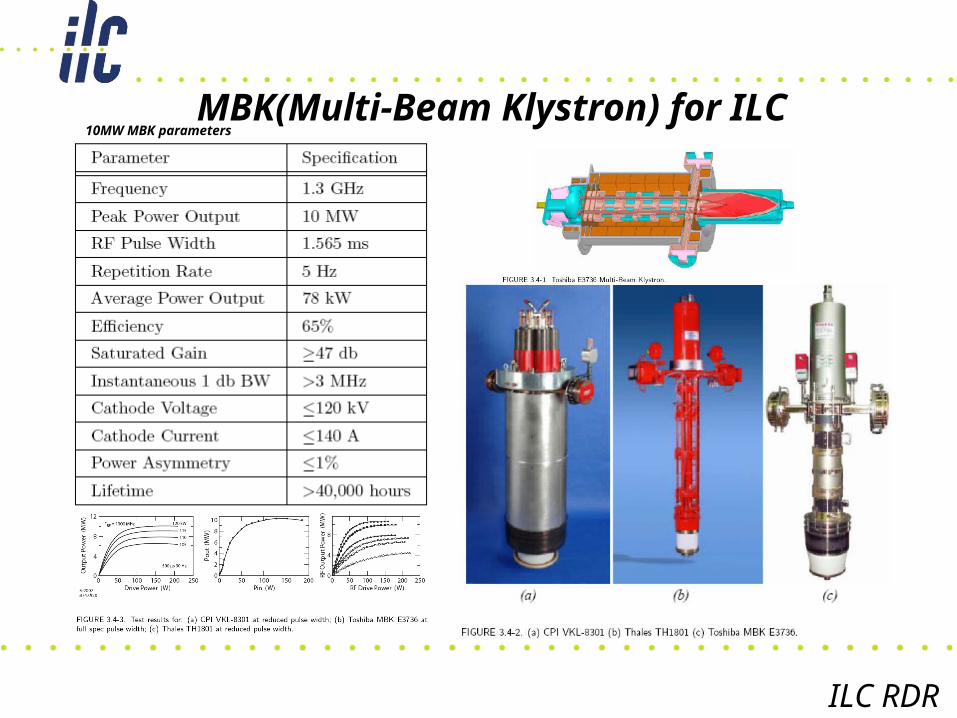
10MW MBK parametersMBK(Multi-Beam Klystron) for ILC
ILC RDR

10MW SBK 5MW IOT 10MW MBK (64kV)

Pros. and Cons.
Pros. Cons.
- Low cost
- Easy installation in the
tunnel
- No expensive modulator
- Economic maintainability
- No L-band yet
- Not easy to increase freq.
- Need fund to make
prototype and industrialize
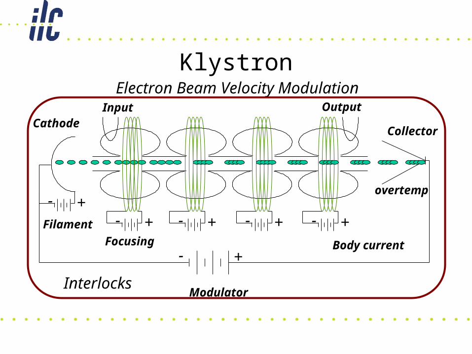
Klystron
CathodeCollector
Electron Beam Velocity Modulation
+-
Modulator
Input Output
+- +- +- +-Focusing
+-Filament
Body current
overtemp
Interlocks

IOTElectron Beam Density Modulation
Cathode
+-
Power Supply
Input
Bias Voltage
+-Filament
Interlocks
Collector
Output
+-
Body current
overtemp
+ -

What’s new?
• Planar IOT (Inductive Output Tube)• Horizontal Design• L-band (1.3GHz) 5MW Tube• Calculation of Design Parameters• Feasible RF interaction Cavity

Equivalent Circuit Approximation
• Capacitance– from Gauss’ Law
• Inductance– from Ampere’s Law
• Resonance Frequency
• Unloaded Q
Lumped-constant circuit
i(t)
V(t) C R L

HOM IOT
Ez field in the interaction region H field in the interaction region
L-band HOM IOT Cavity S-parameters of L-band HOM IOT
Ez field in the interaction regionf(cold)=1.1GHz (MAGIC)

Beam Voltage 55 kV (nom)
Beam Current 123 A (nom)
Frequency 1.3 GHz
Gain - dB (min)
Efficiency ~70 % (nom)
Cathode Loading <1.0 A/cm2
Design Specifications

Pre-modulated Electron Beam
T/2 T 3T/2 2T 5T/2t
I0
I
0Pre-modulated electron beam in current v.s. time ; cut-off sinusoidal current which is used in class B operation, I = I0 MAX(sinwt, 0).
Electron Gun

Cavity Design
Electric field intensity in RF resonator on the gap-centered cross section. This shows the cavity has TM01-mode where the resonator frequency is 1.255GHz in the absence of conductivity of cavity and electron beam.
S-parameters of the RF resonator ; real (red) and imaginary (blue) values which shows us its cold frequency is 1.255GHz. (TM01-mode)
cathode area = 300cm2
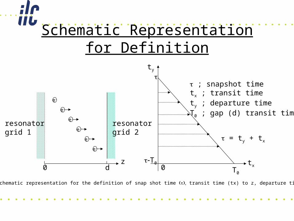
Schematic Representation for Definition
ty
tx
T0
T00
; snapshot timetx ; transit timety ; departure timeT0 ; gap (d) transit time
= ty + tx
e-
e-
e-
e-
e-
e-
resonatorgrid 1
resonatorgrid 2
zd0
Schematic representation for the definition of snap shot time transit time (tx) to z, departure time (ty).
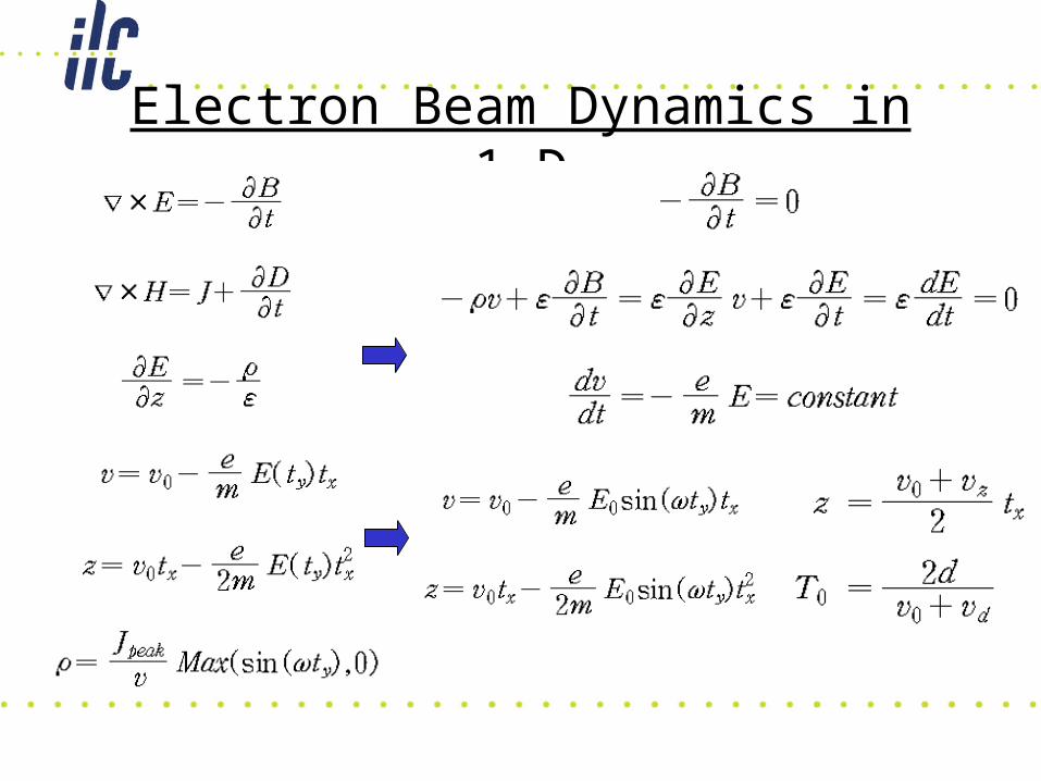
Electron Beam Dynamics in 1-D

Output Power & Gap Field

Gap Field & Efficiency
From resonator field theory,

Design efforts for IOT (ILC) started.
This feasibility study to design IOT for ILC looks very positive.
Design parameters are calculated along with its performance.
Final electrical design will be released soon. And industrialization will be considered. (Toshiba,CPI,…)
After fund is available, more flexible design will be performed and more resources will be put in.
SUMMARY