hygienic air handling units according to din...
TRANSCRIPT

Hygienic Air Handling Units according toDIN 1646-4

Casing
• Interior parts of the air handling unit shall be suitable for cleaning. Non-
smooth surfaces are not allowed.
• Within an air handling unit, all metal parts shall be corrosion-resistant.
• Standard Systemair application;
• 304 quality (AISI/ASTM/UNS) (EN 1.4301) stainless steel is usedfor standard application for inner surfaces.
• 100 micron Epoxy-Polyester painted 275 g/m² galvanized sheet for outer surfaces.
Casing
• All plastic parts located at supply air side
should be selected and used non-microbical
and without non-smooth surfaces according to
ISO 846 (Evaluation of the action of
microorganisms)

Casing
• Casing materials which come in contact with the
air flow shall be resistant to disinfectants.
• Twin wall observation glasses shall be supplied for
fan, filter and humidifier sections with at least
150 mm diameter. Inner parts of the obs. glass
shall be smooth.

Casing
• Humidifier, filter and fan sections shall be accompanied with light fixtures. In order to prevent contamination within the air handling unit, electrical installations shall be located at topside. Light fixtures also shall not contain any non-smooth surface.
• For cleaning purposes, all air handling unit components shall be accessible from both upstream and downstream.
Casing
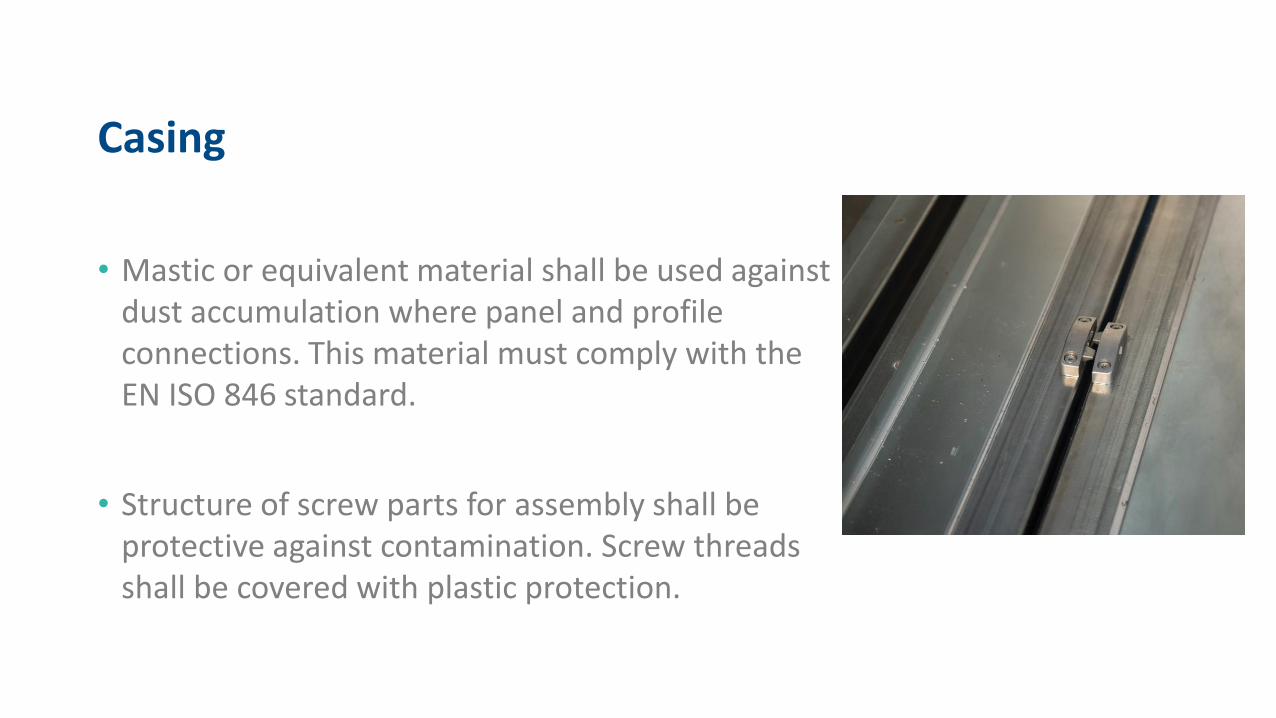
• Mastic or equivalent material shall be used against dust accumulation where panel and profile connections. This material must comply with theEN ISO 846 standard.
• Structure of screw parts for assembly shall be protective against contamination. Screw threads shall be covered with plastic protection.

Casing
• According to EN 1886* standard, casing shall comply with the
following class requirements,
DIN 1946-4 Requirement
Market Requirement
Mechanical Strength D2 D1
Casing Air Leakage Rate L2 L1
Filter Bypass LeakageRate
F9 F9
Thermal Transmittance T3 T2
Thermal Bridging TB3 TB2* EN 1886Ventilation for buildings. Air handling units. Mechanical performance

Drain Pans• Drain pans shall be made of 304 type stainless steel or equivalent material.
• Drain pan shall be provided for;
-Fresh air inlet
-Cooling Coil
-Humidifier/Dehumidifier
-Heat Recovery Unit (Both for supply and extract inlets)
• Diameter of drainage pipes shall be minimum 40 mm and connected to siphon in order to prevent back flow.
• Drain pan shall be tested on negative pressure to ensure that 5 lt/m2 of water can be drained within 10 minutes.
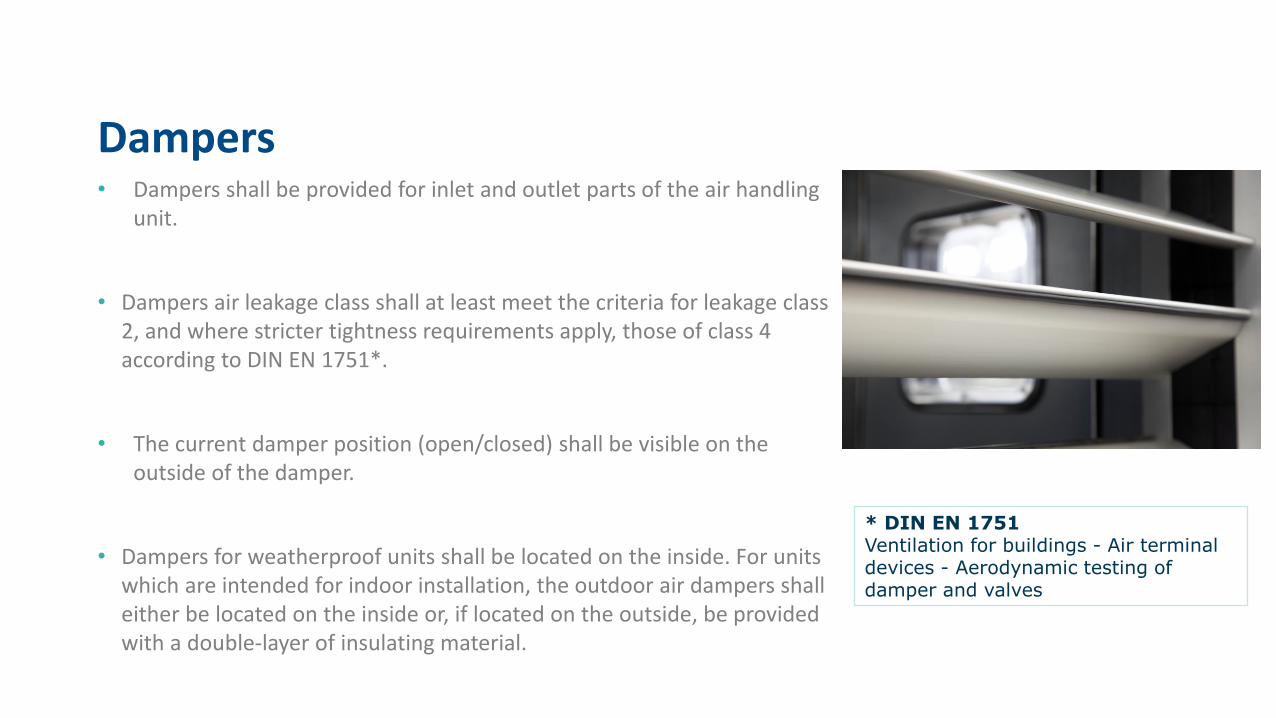
Dampers• Dampers shall be provided for inlet and outlet parts of the air handling
unit.
• Dampers air leakage class shall at least meet the criteria for leakage class 2, and where stricter tightness requirements apply, those of class 4according to DIN EN 1751*.
• The current damper position (open/closed) shall be visible on the outside of the damper.
• Dampers for weatherproof units shall be located on the inside. For units which are intended for indoor installation, the outdoor air dampers shall either be located on the inside or, if located on the outside, be provided with a double-layer of insulating material.
* DIN EN 1751Ventilation for buildings - Air terminal devices - Aerodynamic testing of damper and valves
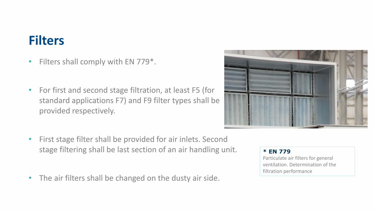
Filters
• Filters shall comply with EN 779*.
• For first and second stage filtration, at least F5 (for standard applications F7) and F9 filter types shall be provided respectively.
• First stage filter shall be provided for air inlets. Second stage filtering shall be last section of an air handling unit.
• The air filters shall be changed on the dusty air side.
* EN 779Particulate air filters for general ventilation. Determination of the filtration performance

Filters
• Differential pressure switches for filter applications shall be provided on the exterior of an air handling unit.
• Within the first stage filtration, in the case of air temperature and relative humidity values are higher than 0 °C whereas %80 and relative humidity value is higher than %90 for any temperature value, electrical heater shall be provided to increase air temperature up to 3 °C.
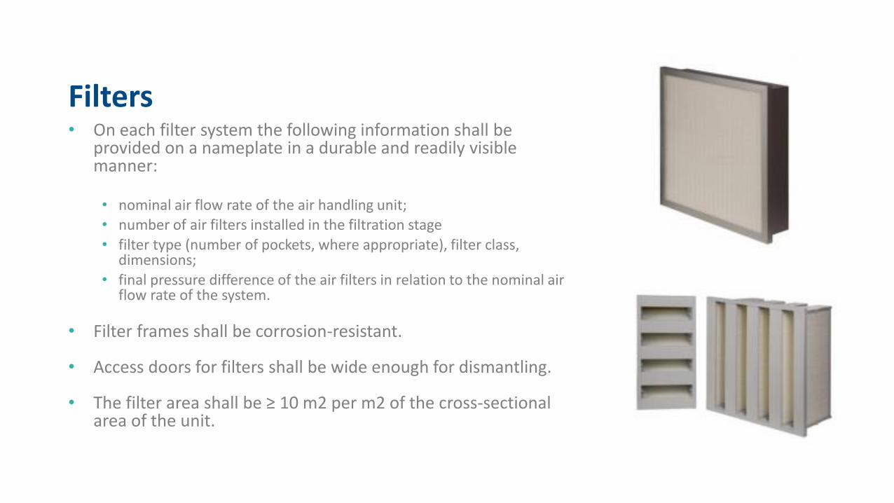
Filters• On each filter system the following information shall be
provided on a nameplate in a durable and readily visiblemanner:
• nominal air flow rate of the air handling unit;• number of air filters installed in the filtration stage
• filter type (number of pockets, where appropriate), filter class, dimensions;
• final pressure difference of the air filters in relation to the nominal air flow rate of the system.
• Filter frames shall be corrosion-resistant.
• Access doors for filters shall be wide enough for dismantling.
• The filter area shall be ≥ 10 m2 per m2 of the cross-sectional area of the unit.
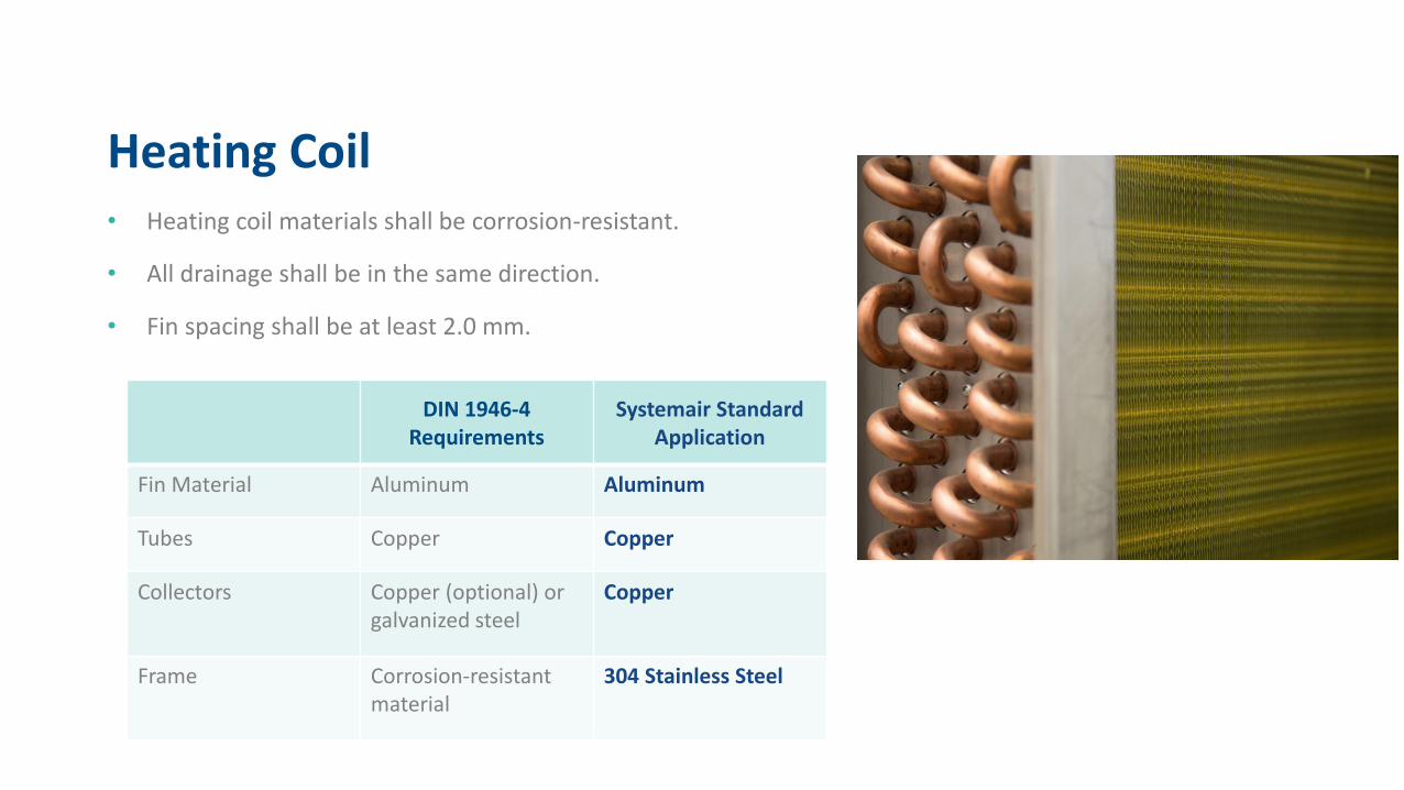
Heating Coil• Heating coil materials shall be corrosion-resistant.
• All drainage shall be in the same direction.
• Fin spacing shall be at least 2.0 mm.
DIN 1946-4 Requirements
Systemair StandardApplication
Fin Material Aluminum Aluminum
Tubes Copper Copper
Collectors Copper (optional) or galvanized steel
Copper
Frame Corrosion-resistantmaterial
304 Stainless Steel

Cooling Coil• Cooling coil materials shall be corrosion-resistant.
• All drainage shall be in the same direction.
• Fin spacing shall be at least 2.5 mm.
• Cooling coil shall be provided before the second stage filtration.
• Within a cooling coil, number of fin rows shall not exceed 10 and fin depth shall be 300 mm max.
DIN 1946-4 Requirements
Systemair Standard Application
Fin Material Aluminum Aluminum
Tubes Copper Copper
Collectors Copper Copper
Frame 304 Stainless Steel 304 Stainless Steel

Cooling Coil – Droplet Seperators
• In order to prevent water flow within the sections where air flow is above 2.8 m/s, droplet seperatorsshall be provided. At least 120°C fire-resistant material shall be provided for droplet eliminators.
• Service doors or removable panels shall be provided with the droplet eliminators for easy maintenance.
• Collector opening diameter shall be wide enough to apply polyurethane foam to avoid condensation within the collector-panel connection.

Heat Recovery
• All requirements for cooling and heating coilapplications shall also be valid for heat recovery units.
• Heat recovery systems shall be provided after the firststage filtration.
• Condensation pans shall be supplied both sides of a heat recovery systems. (Inlet and outlet)

Fans• Plug fans should be preferred. However, centrifugal fans
with a drainage opening and an observation glass can also be selected for hygienic applications. (Std. App. Plug Fan )
• Fans shall be located between the first and last filter sections.
• Necessary empty section shall be provided where humidifier is supplied before the fans in order to avoid humidified air suction.
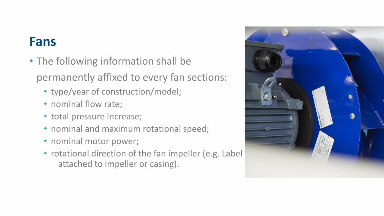
Fans
• The following information shall be
permanently affixed to every fan sections:• type/year of construction/model;
• nominal flow rate;
• total pressure increase;
• nominal and maximum rotational speed;
• nominal motor power;
• rotational direction of the fan impeller (e.g. Labelattached to impeller or casing).

Humidifiers
• Humidifiers shall be provided before the second grade
filtration.
• Relative humidity at outlet air of humidifiers shall not
exceed %90.
• Absorbtion distance shall be complied with humidifier
manufacturers technical documentations.

Attenuators
• Casing material shall be 304 stainless steel.
• Attenuators shall be provided between the first and second grade filtration.
• Attenuators shall not be provided before a humidifier or a cooling coil for dehumidification.

Thank you for listening!