hydropneumatic spring & damper assy sheet size · pdf fileunless otherwise noted: 1 2 all...
TRANSCRIPT
21Unless otherwise noted:
All edges to be deburredAll dimensions in mmSurface roughness, Ra in um:Dimension tolerances according to ISO 2768-1 class:
UIS_MTVR-ASM003-02-B
Sheet: of
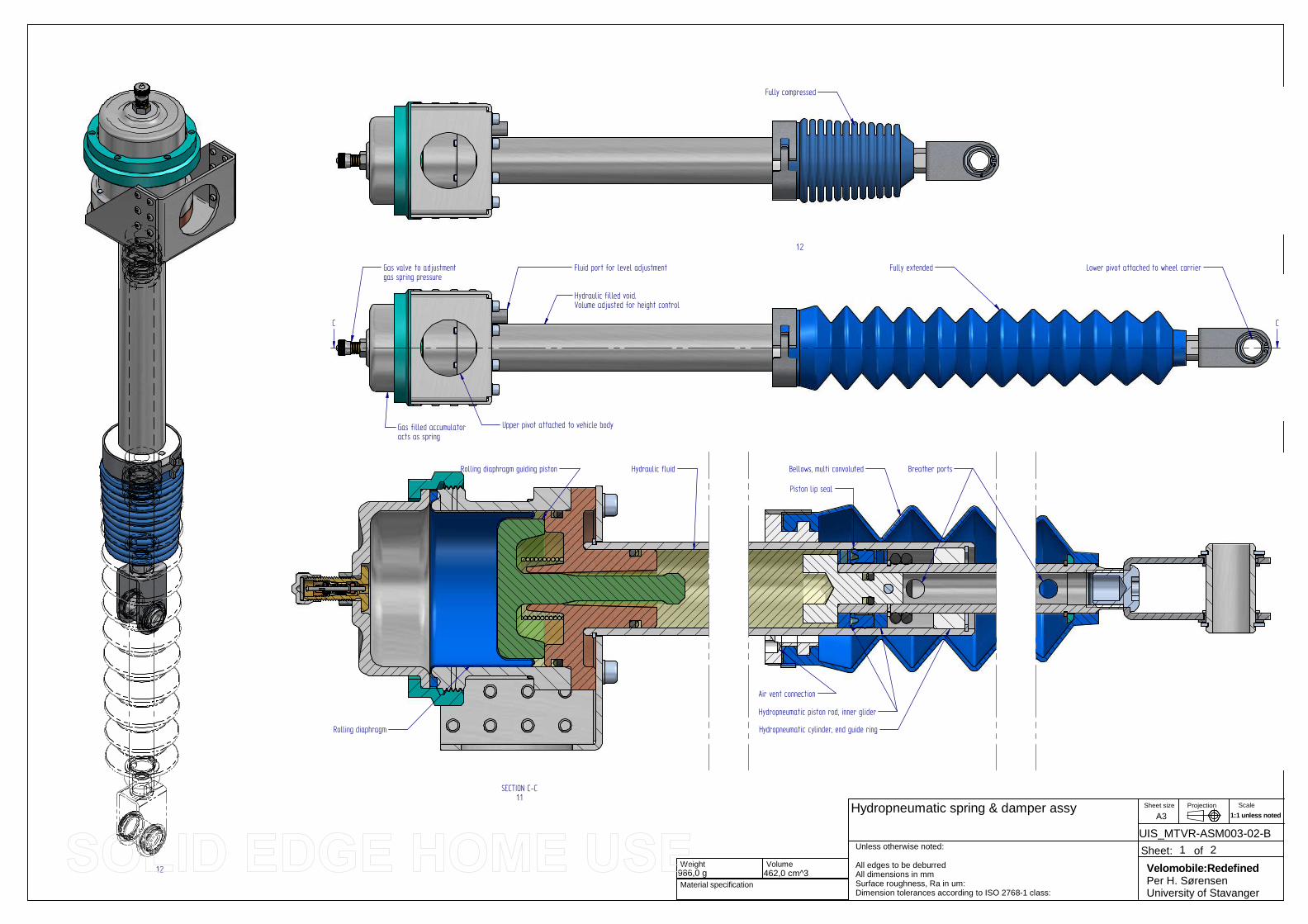
Hydropneumatic spring & damper assy
986,0 g Material specification
462,0 cm^3 Volume
Weight
ProjectionSheet size
A3Scale
1:1 unless noted
Velomobile:RedefinedPer H. SørensenUniversity of Stavanger
C C
SECTION C-C1:1
Gas valve to adjustmentgas spring pressure
Rolling diaphragm guiding piston
Rolling diaphragm
Fluid port for level adjustment
Bellows, multi convoluted
Hydropneumatic cylinder, end guide ring
Piston lip seal
Hydropneumatic piston rod, inner glider
Breather ports
Gas filled accumulatoracts as spring
Hydraulic filled void.Volume adjusted for height control
Lower pivot attached to wheel carrier
Upper pivot attached to vehicle body
1:2
1:2
Fully compressed
Fully extended
Air vent connection
Hydraulic fluid

22Unless otherwise noted:
All edges to be deburredAll dimensions in mmSurface roughness, Ra in um:Dimension tolerances according to ISO 2768-1 class:
UIS_MTVR-ASM003-02-B
Sheet: of
Hydropneumatic spring & damper assy
986,0 g Material specification
462,0 cm^3 Volume
Weight
ProjectionSheet size
A3Scale
1:1 unless noted
Velomobile:RedefinedPer H. SørensenUniversity of Stavanger
516
341
175
601
72
A
A
SECTION A-A
Item Title Document Number Qty Material Material grade Mass(Item)
Mass(Qty)
1 Schrader 50bar valve assy Schrader OEM 1 9,2 g 9,2 g
2 Hydropneumatic cylinder, ID25 UIS_MTVR-PAR104 1 Aluminum, 5050 145,1 g 145,1 g
3 Blind rivet Popnail Ø3.2 L6 16 Aluminum, 5050 0,3 g 4,8 g
4 Hydropneumatic spring & damper, top bracket UIS_MTVR-PSM101 1 Aluminum, 5050 70,5 g 70,5 g
5 Hydropneumatic accumulator, center UIS_MTVR-PAR101 1 Aluminum, 6061-T6 107,4 g 107,4 g
6 Hydropneumatic accumulator, top UIS_MTVR-PAR102 1 Aluminum, 6061-T6 54,0 g 54,0 g
7 Hydropneumatic accumulator, screw ring UIS_MTVR-PAR103 1 Aluminum, 6061-T6 46,7 g 46,7 g
8 Hydropneumatic piston rod UIS_MTVR-PAR109 1 Aluminum, 6061-T6 81,1 g 81,1 g
9 Hydropneumatic piston rod, end bracket bolt UIS_MTVR-PAR112 1 Aluminum, 6061-T6 6,5 g 6,5 g
10 Hydropneumatic accumulator, base UIS_MTVR-PAR114 1 Aluminum, 6061-T6 97,5 g 97,5 g
11 Scharder valve, external nut NA 1 Brass, yellow brass 1,5 g 1,5 g
12 Hydraulic fluid TBD 1 Hydraulic fluid 102,7 g 102,7 g
13 seal o-ring 1 NBR 1,1 g 1,1 g
14 seal o-ring 20x2.6 1 NBR 0,5 g 0,5 g
15 Rolling diaphragm Simrit BFA 50 45 40 2365 1 NBR 50 NBR 253 6,4 g 6,4 g
16 o-ring o-ring 15.47 x 3.53 2 NBR N674-70 0,7 g 1,4 g
17 o-ring O-ring 5,23x2,62 1 NBR N747-75 0,2 g 0,2 g
18 o-ring, Parker 2-008, 4,47x1,78 Parker # 2-008 1 NBR, 70 sh N674-70 0,1 g 0,1 g
19 Polymer slide bearing, Ø17, for sheet T=2 IGUS MCM 16-02 2 Nylon, general purpose 0,3 g 0,6 g
20 Guide piston for diaphragm UIS_MTVR-PAR107 1 Nylon, general purpose 24,1 g 24,1 g
21 Bellows holder, with vent port UIS_MTVR-PAR108 1 Nylon, general purpose 15,1 g 15,1 g
22 Hydropneumatic piston, end plug UIS_MTVR-PAR110 1 Nylon, general purpose 5,9 g 5,9 g
23 Bellows, multi convoluted Simrit V6-404 428849 1 Polychloroprene 77,7 g 77,7 g
24 Piston lip seal OD 30 1 Polyurethene 1,8 g 1,8 g
25 Hydropneumatic cylinder, end guide ring UIS_MTVR-PAR106 1 PTFE Unfilled 4,0 g 4,0 g
26 Hydropneumatic piston rod, inner glider UIS_MTVR-PAR111 2 PTFE Unfilled 1,2 g 2,4 g
27 Guide piston spring UIS_MTVR-PAR115 1 Stainless steel Spring temper 5,3 g 5,3 g
28 lock ring, external DIN 471 Ø16 4 Stainless steel Spring temper 0,7 g 2,9 g
29 Lock ring, external, Ø30 DIN 471 Ø30 1 Stainless steel Spring temper 1,5 g 1,5 g
30 Seeger ring, for bore, 19mm DIN 472 19mm 1 Stainless steel Spring temper 1,6 g 1,6 g
31 Hose clamp, self energized, Ø48 1 Stainless Steel, 304 23,7 g 23,7 g
32 Parallel Pin DIN 7, OD5 L15 1 Stainless Steel, 304 0,8 g 0,8 g
33 Fluid port hose connection UIS_MTVR-PAR105 1 Stainless Steel, 304 7,2 g 7,2 g
34 bolt DIN 912 M4x25 8 Stainless Steel, 316 3,5 g 28,2 g
35 Bolt, M12x1.5 L12, for rod end UIS_MTVR-PAR113 1 Stainless Steel, 316 9,7 g 9,7 g
36 Hydropneumatic piston rod, end bracket UIS_MTVR-PSM102 1 Stainless Steel, 316 31,9 g 31,9 g
37 Spring Washer DIN 127 M4 8 Stainless Steel, 316 A4 0,2 g 1,8 g
38 Washer with rounded outer edge Washer ID16 OD20 1 Stainless Steel, 316 A4-80 2,5 g 2,5 g
B
DETAIL B
O75
52
34
32
37
28
29
19
111
15
16
4
8
10
20
6
5
7
25
2
22
14
13
24
36
9
35
26
31
30
23
21
38
17
18
33
3
27
12

21Unless otherwise noted:
All edges to be deburredAll dimensions in mmSurface roughness, Ra in um:Dimension tolerances according to ISO 2768-1 class:
UIS_MTVR-ASM001-11-B
Sheet: of
Rear Suspension assembly, right
5831.3 g Material specification
8671.4 cm^3 Volume
Weight
ProjectionSheet size
A3Scale
1:1 unless noted
Velomobile:RedefinedPer H. SørensenUniversity of Stavanger
AA
SECTION A-A
295 161
3
O504
O16
9
072
,521
119,8
127,
1 142,
2
47
3,15
169
261
742
3358
130
13
O 30
O 28,6
B
DETAIL B
7,3
26,7
22,4
23,8
49

22Unless otherwise noted:
All edges to be deburredAll dimensions in mmSurface roughness, Ra in um:Dimension tolerances according to ISO 2768-1 class:
UIS_MTVR-ASM001-11-B
Sheet: of
Rear Suspension assembly, right
5831.3 g Material specification
8671.4 cm^3 Volume
Weight
ProjectionSheet size
A3Scale
1:1 unless noted
Velomobile:RedefinedPer H. SørensenUniversity of Stavanger
1:2.5
1:2.5
1
17
19
3
16
5
157
12
10
913
11
18
2
14
20
Item Title Document Number Material Qty Mass (Item) Mass (Qty)
Rear Suspension assembly, right UIS_MTVR-ASM001 5872,1 g 5872,1 g
1 Ball bearing, cycle, fork, bottom A118SAK_BOT Steel 1 52,7 g 52,7 g
2 Ball bearing, cycle, fork, top A118SAK TOP Steel 1 83,4 g 83,4 g
3 Bolt DIN912 M6x45 A4 80 2 13,4 g 26,7 g
4 Brake caliper assy, minimoto Unspecified 1 288,3 g 288,3 g
5 Hexagon Socket Head Cap Screws,din912
DIN 912 M6x20 A4 2 7,6 g 15,3 g
6 hub motor torque arm, "e" UIS_MTVR-PSM0300 Stainless Steel, 316 1 41,0 g 41,0 g
7 Polymer bearing, spherical Ø16 IGUS ESTM-16-1 Nylon, general purpose 1 16,7 g 16,7 g
8 Rear motor & wheel assembly UIS_MTVR_ASM002 1 4238,3 g 4238,3 g
9 Rear suspension, damper bearingholder
UIS_MTVR-PSM0201 Aluminum, 5050 1 58,6 g 58,6 g
10 Rear suspension, inside, left UIS_MTVR-PAR0112 Aluminum, 6061-T6 1 376,6 g 376,6 g
11 Rear suspension, inside, left UIS_MTVR-PSM0200 Aluminum, 5050 1 100,1 g 100,1 g
12 Rear suspension, inside, right UIS_MTVR-PAR0113 Aluminum, 6061-T6 1 376,7 g 376,7 g
13 Rear suspension, profiled stiffener UIS_MTVR-PSM0202 Aluminum, 5050 1 86,2 g 86,2 g
14 Rivet nut, thin plate MINOFF M6-008-4MM-Z Stainless steel 2 2,7 g 5,3 g
15 Rivet nut, thin plate MINOFF M5-008-4MM-Z Stainless steel 8 1,4 g 11,1 g
16 Rivet Ø3,2 Rivet SS 316 70 0,6 g 38,9 g
17 Screw UNI ISO 7380 M5 x 16 Steel 8 3,3 g 26,7 g
18 Suspension bearing reinforcement UIS_MTVR-PAR0301 Aluminum, 6061-T6 1 25,1 g 25,1 g
19 Washer DIN 125 M6 A4 2 1,0 g 2,0 g
20 Wedge nut, hand grinded to adddraft
Square nut Aluminum, 5050 1 2,3 g 2,3 g
68
4
1:6

11
3D filename:
Unless otherwise noted:
All edges to be deburredAll dimensions in mmSurface roughness, Ra in um:Dimension tolerances according to ISO 2768-1 class:
UIS_MTVR-ASM301-00-A
Sheet: of
UIS_MTVR-ASM301 Blow thermoforming of canopy
0,000 g Material specification
Finish
0,0 cm^3 Volume
Density
Weight
07.06.2014 3D last edited: 3D doc. number:
Canopy production-00.asm
ProjectionSheet size
A3Scale
1:1 unless noted
Velomobile:Redefined
University of Stavanger
1:10
241
100
617
2 mm PETG - UV stabilized
Air inlet
2378
19 mm plywood
19 mm plywood
R50
56
800
2309(projected length after bending)
Cutout shape extracted from CAD model
1:20
1:20
Spacing and size of bolts depend on blow pressure.Illustration shows 100 mm between M10 bolts suitable for 1 bar (0.1 MPa)This result in approx 13 ton of total force on blow mold or around 250 kg for each bolt.
Area approx 1.3 m^2

O44
Disc r
otor B
CD
M5(6X
)
O3,5
Spoke holes
(2 x 18 holes)
To keep dishing, or offset between hub and rim to a minimum:Use narrow spacing between minimotor and fork on this sidewith disk brake bolts)
Shim the gap between minimotor and fork only on this side (Wire side). Typically 2 mm shim is needed
98 typical
Centerline for 100 mm wide fork withshims on right side only.
14,9 28,8
50
Base of disc brake rotor
6,4
Hub dimensions necessary for building wheels: GM minimotor (Front hub)
O 130Spoke hole CD
Housing ball bearing 6001-2RS
Lid ball bearing 16003-2RSPlease observe that some lids has beensupplied with 16003Z which is not water proof!
Hexagon socket head cap screw DIN 912 - M4x10
The illustrations containsdimensions for the current minimotor.
Spoke related dimensions for the oldblack minimotor hub can be found in thetable in the lower right corner.
The black minimotor also differs byusing 6003 bearing and philips M4screws on lid and 20% wider plasticplanet gears. Both old and newmotor/gear assy will however fit eitherhousing.
LidHousing
Disc rotor isusually 2mm leaving notmore than approx 4 mmfor rotor bolt heads

100
4.7uH
3.3n
3.3n
22u
100
4.7uH
3.3n
3.3n
22u
100
4.7uH
3.3n
3.3n
22u
100
4.7uH
3.3n
3.3n
22u
100
4.7uH
3.3n
3.3n
22u
100
4.7uH
3.3n
3.3n
22u
100
4.7uH
20k
3.3n
3.3n
22u
100
4.7uH
20k
3.3n
3.3n
22u
100
4.7uH
3.3n
3.3n
22u
100
4.7uH
20k
3.3n
3.3n
22u
100
4.7uH
3.3n
3.3n
22u
22u
0.1u
0.1u
0.1u
0.1u
0.1u
0.1u
0.1u
0.1u
0.1u
0.1u
0.1u
5.6V
5.6V
5.6V
5.6V
5.6V
5.6V
5.6V
5.6V
5.6V
5.6V
5.6V
5.6V
0.1u
10u
10u
10u
10u
10u
10u
10u
10u
10u
10u
10u
10u
MA
21D
380G
MA
21D
380G
5.6V
0.1u 10u
5.6V
0.1u 10u
5.6V
0.1u 10u
5.6V
0.1u 10u
100
4.7uH
3.3n
3.3n
22u
100
4.7uH
3.3n
3.3n
22u
100
4.7uH
3.3n
3.3n
22u
100
4.7uH
3.3n
3.3n
22u
10n
10n
10n
10n
10n
10n
10n
10n
10n
10n
10n
10n
10n
10n
10n
T1ANT1AP
R3A
L1A
R1A
R2A
C1A
C2A
C3A
T1BNT1BP
R3B
L1B
R1B
R2B
C1B
C2B
C3B
T1CNT1CP
R3C
L1C
R1C
R2C
C1C
C2C
C3C
T1DNT1DP
R3D
L1D
R1D
R2DC
1DC
2D
C3D
T1ENT1EP
R3E
L1E
R1E
R2E
C1E
C2E
C3E
T1FNT1FP
R3F
L1F
R1F
R2F
C1F
C2F
C3F
T1GNT1GP
R3G
L1G
R1G
R2G
C1G
C2G
C3G
T1HNT1HP
R3H
L1H
R1H
R2H
C1H
C2H
C3H
T1INT1IP
R3I
L1I
R1I
R2I
C1I
C2I
C3I
T1PNT1PP
R3P
L1P
R1P
R2P
C1P
C2P
C3Q
T1JNT1JP
R3J
L1J
R1J
R2J
C1J
C2J
C3J
C3P
C4A
C4B
C4C
C4D
C4E
C4F
C4G
C4H
C4I
C4J
C4K
D2A
D2B
D2C
D2D
D2E
D2F
D2G
D2H
D2I
D2J
D2K
D2L
C4L
C5A
C5B
C5C
C5D
C5E
C5F
C5G
C5H
C5I
C5J
C5K
C5L
D3A
D1A
D3P
D3J
D3I
D3H
D3G
D3F
D3E
D3D
D3C
D3B
D1B
D1C
D1D
D1E
D1F
D1G
D1H
D1I
D1J
D1P
FID1FID2
FID4
D2M
C4M C5M
D2N
C4N C5N
D2P
C4P C5P
D2Q
C4Q C5Q
T1NNT1NP
R3N
L1N
R1N
R2N
C1N
C2N
C3N
D3N
D1N
T1MNT1MP
R3M
L1M
R1M
R2M
C1M
C2M
C3M
D3M
D1M
T1LNT1LP
R3L
L1L
R1L
R2L
C1L
C2L
C3L
D3L
D1L
T1KNT1KP
R3K
L1K
R2K
C1K
C2K
C3K
D3K
D1K
C6P
C6N
C6M
C6L
C6K
C6J
C6I
C6G
C6F
C6E
C6D
C6C
C6B
C6A
C6H
TP
-V0
BUS_BAT:V[0..16],TEMP[1..4]
P1NP1N/3.4D
P5SP5S/2.7D
P5NP5N/2.7D
P6SP6S/2.7D
V0V0
V1V1
V2
V2
V3
V3
V4
V4
V12
V12
P7SP7S/2.7C
P7NP7N/2.7C
P8SP8S/2.7C
P9SP9S/2.7B
P9NP9N/2.7A
P10SP10S/2.7A
V5
V5
V6
V6
V7
V7
V8
V8
V9
V9
V9
V11
V11
V10
V10
V10
P11SP11S/2.5D
P4NP4N/3.4C
P4SP4S/3.5C
P3NP3N/3.4C
P3SP3S/3.5C
P2NP2N/3.4D
P2S/3.5D
P10N/2.7A P10N
P8N/2.7B
P6N/2.7D
V15
V15
V16
V16
V14
V14
V13
V13
P12N/2.5D P12N
P13N/2.5C
P14SP14S/2.5B
P12SP12S/2.5D
P11N/2.5D P11N
P15NP15N/2.5A
P16SP16S/2.5A
P15SP15S/2.5A
P14N/2.5B
P13SP13S/2.5C
A
B
C
D
E
1 2 3 4 5 6 7 8
A
B
C
D
E
1 2 3 4 5 6 7 8
C4x and D2x near connectorC5x near IC pins
Temp1
Temp3
Temp2
10n
10n
10u
10u
1N41
48
1n
10n
10n
10n
10n
10u
10u
10u
10u
1N41
48
1n
1N41
48
1n
1N41
48
1n
Thermally connected to heatsink
POWERFET temp sensor
C15
C13
C14
C12
DT
4
CT4
J1-1
J1-2
J2-1
J2-2
J3-1
J3-2
C23
C21
C19
C17
C22
C20
C18
C16
J5-4
J5-5
J5-6
J5-7
J5-8
J5-9
J5-10
J5-11
J5-12
J5-13
J5-14
J5-15
J5-16
J5-17
J5-18
J5-19
J5-20
J5-21
J5-22
J5-23
J5-24
J5-25
J5-26
J5-28
J5-29
J5-30
J5-31
J5-32
J5-33
J5-34
J5-27
J5-1
J5-2
J5-3
TMD11
TCK10
TDI3
T213
T114
V212
V115
VSS1 TAB
TAB
VLDO 2
VPP 16
SDI 4
SDO 9
P1S 5
P1N 6
P2S 7
P2N 8
U11BQ76PL102_NOVIASNO_VIAS
TMD11
TCK10
TDI3
T213
T114
V212
V115
VSS1 TAB
TAB
VLDO 2
VPP 16
SDI 4
SDO 9
P1S 5
P1N 6
P2S 7
P2N 8
U12BQ76PL102_NOVIASNO_VIAS
TMD11
TCK10
TDI3
T213
T114
V212
V115
VSS1 TAB
TAB
VLDO 2
VPP 16
SDI 4
SDO 9
P1S 5
P1N 6
P2S 7
P2N 8
U13BQ76PL102_NOVIASNO_VIAS
TMD11
TCK10
TDI3
T213
T114
V212
V115
VSS1 TAB
TAB
VLDO 2
VPP 16
SDI 4
SDO 9
P1S 5
P1N 6
P2S 7
P2N 8
U14BQ76PL102_NOVIASNO_VIAS
TMD11
TCK10
TDI3
T213
T114
V212
V115
VSS1 TAB
TAB
VLDO 2
VPP 16
SDI 4
SDO 9
P1S 5
P1N 6
P2S 7
P2N 8
U15BQ76PL102_NOVIASNO_VIAS
TMD11
TCK10
TDI3
T213
T114
V212
V115
VSS1 TAB
TAB
VLDO 2
VPP 16
SDI 4
SDO 9
P1S 5
P1N 6
P2S 7
P2N 8
U16BQ76PL102_NOVIASNO_VIAS
DT1
CT1
TEMP11
REF11
DT2
CT2
TEMP12
REF12
DT3
CT3
TEMP13
REF13
BUS_BAT:V[0..16],TEMP[1..4]
V0
V0
V0V0
V2
V2
V2V2
V4
V4V4
V12
V12
V12V12
V5
V5V5
V6
V6
V6V6
V7
V7V7
V8
V8
V8V8
V9
V9V9
V11
V11V11
V10
V10
V10V10
V15V15V15
V16
V16V16
V14
V14
V14V14
V13
V13V13
TEMP3
TEMP4
TEMP2
TEMP1
P13S/1.6C
P13N/1.6B
P14S/1.6B
P14N/1.6B
P15S/1.6B
P15N/1.6A
P16S/1.6A
P5S/1.3C
P5N/1.3C
P6S/1.3B
P7S/1.3B
P7N/1.3B
P8S/1.3A
P9S/1.3A
P9N/1.6E
P10S/1.6D
P12S/1.6C
P11S/1.6D
P11N/1.6D
P10N/1.6D
P8N/1.3A
P6N/1.3BP12N/1.6C
SDO.U1/3.6C
V3V3
V1V1
A
B
C
D
E
1 2 3 4 5 6 7 8
A
B
C
D
E
1 2 3 4 5 6 7 8

BAT STAT (Reed switch)
J4
Precharge current limit
2512 50 ppm/°C
D2PAKD2PAK
Discharge switch Charge switchPrecharge switchBattery filter & fuse Noise filter and overvoltage protection
Kickstart
10n
1u
4.7k
4.7k
0.1u10u
10k
10n
10n
100k
10u
1M
1M
4.7k
270
1M
100
100
100
5.6V
5.6V
100
100
1M 1M
1M
1M
100n 100V 100n 100V
1M
5.6V4.7k 4.7k
1M
1n
SM
CJ4
8CA1K 1W
1K 1W
short!
5.6V
100n 100V200V
10A
1M
LM50
50-1
LM5050-1
100V 100mA
100n 100V
100n 100V
4.7k
BSS84
BSS63
100k
100k
1n
BSS123
BSS123 10M
1M
1M
BSS123
BSS123
1 milliohm 2W
MOUNT-HOLE3.0
MOUNT-HOLE3.0
MOUNT-HOLE3.0
100k
FQT7N10-SOT223_4
5.6V
5.6V
1n
4.7k
1M
10u
1M
10M
10M
D12
5 D12
4
D12
3
D12
2
D12
1
C11
0C
111
R11
9
R11
8
C109
C108
R117
C107
C10
6
R116
C10
5
R126
R127
R124
R121
R111
R11
5
R133
R132
D11
8
D11
7
R129
R128
R13
0
R13
1
T108
R114
R101
C104 C103
R108
D116
R123 R125
R12
2
C113
D10
4
SW1
R104
R105
CE
LLS
+
B.+
LOA
D+
P.+
LOA
D-
P.-
B.-
CE
LLS
-
J4G$1
J4G$2
J4G$3
J4G$4
21SJ1
P4S22
P3N21
P3S20
P2N17
P2S16
P1N15
SDO013
SDI114
SDO218
SDI319
VLDO18
RSTN25
P4N23
V147V244
V439
VLDO243
SPROT30
PRE3
CHG1
DSC
V342
XT4 40
XT3 41
XT2 45
XT1 46
LED5 36
LED4 35
LED3 34
LED2 33
LED1 32
PSH 31
FIELD 29
P-LAN 24
EFCID 5
EFCIC 4
SERCLK 26
SERDIN 27
SERDOUT 28
SMBCLK 37
SMBDAT 38
TABTABVSS48
OSCI 11
OSCO 12
CS
BA
T9
CC
BA
T6
CC
PA
CK
7
CS
PA
CK
10
U103BQ78PL114
D101
C114
D10
3
R102
OFF3
GN
D2
GA
TE
5
IN4
OU
T6
VS 1
U102
T102
OFF3
GN
D2
GA
TE
5
IN4
OU
T6
VS 1
U101
D102
C102
C101
R112
T111
T109
R11
0R
109
C112
T103
T110
R11
3
R103
R106
T106
T105
R120
T101T107
SPROT
H1
H2
H3TP_CSBAT TP_CSPACK
TP_VLD01
TP_V0
TP_PE
TP
_CE
LLS
-
R10
7
Q1
D1
D120
C1114
R135
R13
4
C100
R100
J6-1
J6-2
R13
7
R13
6
F1
BU
S_B
AT:
V[0
..16]
,TE
MP
[1..4
]
BUS_BAT:V[0..16],TEMP[1..4]
P1N/1.3E
P4N/1.3CP4S/1.3D
P3N/1.3DP3S/1.3D
P2N/1.3DP2S/1.3E
V1
V1
V2
V2
V3V4
TEMP1TEMP2TEMP3TEMP4
VLDO1(+2.5V)
SDO.U1/2.7E
PE
SMBDAT
SMBCLK
DS
C
LOAD+
IEFCIC
CELLS+
CELLSF PWRRAIL
PWRRAIL
CS
PA
CK
CS
BA
T
CELLS-
V0
IEFCID XEFCID
XEFCIC
A
B
C
D
E
1 2 3 4 5 6 7 8
A
B
C
D
E
1 2 3 4 5 6 7 8
16S Ebike BMS for Li-ion
0A30A bidir, 50A peak
TBMS-2-2011/PHS
Max 150mA

1
1225
36
R3A
L1A
R1AR2A
C1A
C2A
C3A
R3B
L1B
R1B
R2B
C1B
C2B
C3B
R3C
L1C
R1CR2C
C1C
C2C
C3C
R3D
L1D
R1DR2D
C1D
C2D
C3D
R3E
L1E
R1ER2E
C1E
C2E
C3E
R3F
L1F
R1F
R2F
C1F
C2F
C3F
R3G
L1G
R1GR2G
C1G
C2G
C3G
R3H
L1H
R1HR2H
C1H
C2H
C3H
R3I
L1I
R1IR2I
C1I
C2I
C3I
R3P
L1P
R1P
R2P
C1P
C2P
C3Q
R3J
L1J
R1JR2J
C1J
C2J
C3JC3PC4A
C4B
C4C
C4D
C4E
C4F
C4G
C4H
C4I
C4JC4K
D2AD2B
D2C D2D
D2E
D2F
D2GD2H
D2ID2J
D2K
D2L C4L
C5A
C5BC5C
C5DC5E
C5FC5GC5HC5IC5JC5KC5L
C11
0
C111
R11
9R
118
C10
9
C10
8
R117C107
C106
R116
C10
5
R12
6R
127
R12
4
R121
R11
1
R115
R13
3
R13
2
D11
8
D11
7
R129
R12
8R
130
R131
T108
R11
4
R101
C10
4C103
R10
8
D11
6
R123
R12
5
R122
C113
D104
D3A
D1A
D3P D3J D3I D3H D3G D3F D3E D3D D3C D3B
D1BD1CD1DD1ED1FD1GD1HD1ID1JD1P
Fid
Fid Fid
D2M
C4M
C5M
D2N
C4N
C5ND2P
C4P
C5P
D2QC4Q
C5Q
R3N
L1N
R1NR2N
C1N
C2N
C3N
D3N
D1N
R3M
L1M
R1MR2M
C1M
C2M
C3M
D3M
D1M
R3L
L1L
R1LR2L
C1L
C2L
C3L
D3L
D1L
R3K
L1K
R1KR2K
C1K
C2K
C3K
D3K
D1K
C6P C6N C6M C6L C6K C6J C6I C6G C6F C6E C6D C6C C6B C6AC6H
C15C13
C14C12
DT4CT
4
C23C21C19C17
C22
C20C18
C16
U11U12U13U14U15U16
U103 D10
1
C114
D103
R102
U10
2
T102
U10
1
D102
C102C10
1
R112
T11
1T
109
R110
R109
C112
T103
T110
R113
R10
3
R10
6
T10
6
T105
R120
T101
T107
DT1CT1
TE
MP
11R
EF
11
DT2CT2
TE
MP
12R
EF
12
DT3CT3
TE
MP
13R
EF
13
R10
7
Q1
D1
D12
0C1114
R13
5
R13
4
C10
0
R10
0
R13
7
R136
100
4.7uH
20k20k
3.3n3.3n
22u
100
4.7uH
20k
20k
3.3n
3.3n
22u
100
4.7uH
20k20k
3.3n3.3n
22u
100
4.7uH
20k20k
3.3n3.3n
22u
100
4.7uH
20k20k
3.3n3.3n
22u
100
4.7uH
20k20k
3.3n3.3n
22u
100
4.7uH
20k20k
3.3n3.3n
22u
100
4.7uH
20k20k
3.3n3.3n
22u
100
20k20k
3.3n3.3n
22u
100
4.7uH
20k20k
3.3n3.3n
22u
100
20k20k
3.3n3.3n
22u22u
0.1u
0.1u
0.1u
0.1u
0.1u
0.1u
0.1u
0.1u
0.1u
0.1u0.
1u
5.6V5.6V
5.6V 5.6V
5.6V
5.6V
5.6V5.6V
5.6V
5.6V5.6V
5.6V
0.1u
10u
10u10u
10u10u
10u10u10u10u10u10u10u
10n
1u
4.7k
4.7k
0.1u
10u
10k10n
10n
100k
10u
1M1M
4.7k
270
1M
100
100
100
5.6V 5.6V
100
100
1M1M
1M
1M
100n
100
V
100n 100V
1M
5.6V
4.7k
4.7k
1M
1n
SM
CJ4
8CA
MA21D380G
MA
21D
380G
MA21D380G MA21D380GMA21D380G MA21D380GMA21D380G MA21D380G MA21D380G
MA21D380GMA21D380GMA21D380G
MA21D380GMA21D380GMA21D380GMA21D380GMA21D380GMA21D380GMA21D380GMA21D380G
MA21D380GMA21D380G
5.6V
0.1u
10u
5.6V 0.
1u
10u
5.6V
0.1u
10u
5.6V0.1u
10u
100
20k20k
3.3n3.3n
22u
MA21D380G
MA21D380G
100
20k20k
3.3n3.3n
22u
MA21D380G
MA21D380G
100
20k20k
3.3n3.3n
22u
MA21D380G
MA21D380G
100
20k20k
3.3n3.3n
22u
MA21D380G
MA21D380G
10n 10n 10n 10n 10n 10n 10n 10n 10n 10n 10n 10n 10n 10n10n
10n10n
10u
10u
1N41
481n
10n10n10n10n
10u
10u
10u
10u
BQ76PL102_NOVIASNO_VIASBQ76PL102_NOVIASNO_VIASBQ76PL102_NOVIASNO_VIASBQ76PL102_NOVIASNO_VIASBQ76PL102_NOVIASNO_VIASBQ76PL102_NOVIASNO_VIAS BQ78PL114
5.6V
100n 100V
200V 10A
1M
LM50
50-1
IPB100N10S3-0
LM50
50-1
100V 100mA
100n 100V100n
100
V
4.7k
BSS84
BS
S63
100k100k
1nBSS123
BS
S12
3 10M
1M
1M
BS
S12
3
BS
S12
3
1 milliohm 2W
IPB100N10S3-0
IPB100N10S3-0
1N4148
1n
1N4148
1n
1N4148
1n
100k
FQ
T7N
10-S
OT
223_
4
5.6V
5.6V
1n
4.7k
1M
10u
1M
10M
10M
3,0
3,0
3,0


VELOMOBILE: redefined
Appendix C
Flow simulations
Two different types of flow simulations has been performed within this thesis work. The major
work has been on reducing aerodynamic drag of the velomobile body by iterative redesigning of
the 3D geometry based on CFD drag calculation of preceding design. Also a single simulation of
ventilation flow has been performed to find base values of ventilation mass and volume flow.
This was necessary for evaluating if ventilation is sufficient for the expected heat flow in the
cabin of the velomobile. Also a ventilation simulation involving flow over human body was tried.
This failed due to too complex 3D model of human body, even after several modification to
simplify geometry.
References: Background in CFD [1], base information on aerodynamics of vehicles [2], and ultra-
streamlining of land vehicles [3].
Simulations has been performed using the following:
Software:
Caedium Professional 5.2 from Symscape, a unified CFD simulation environment based on a port
of OpenFOAM 2.1 to windows. Models has been constructed in Solid Edge versions ST4, ST5 and
ST6 from Siemens. OS has been Windows 8.0 64-bit
Hardware:
Software has been running on a home built PC workstation with X79 motherboard, Intel i7 3920k
6-core CPU and 32 Gbyte RAM. Graphics coprocessor has been NVIDIA GeForce GTX770 with 2
Gbyte RAM and 1536 shader cores capable of working as CFD coprocessors. 3Tbyte 7200 RPM
SATA disk.
Initial parameters:
The automatic meshing in Caedium use three parameters that can be applied to each entity
(surfaces and volume), namely;
• Growth rate - the mesh element growth rate moving away from geometric entity
• Max element size - Maximum size of element
• Resolution - The number of mesh intervals on an entity
The surface mesh edge size is the smallest of either edge length/resolution or max element size
The volume mesh edge size is the smallest of either maximum edge (or bounding box diagonal if
no edge exists) / resolution or max element size. Wind tunnel surfaces has been set to:
• Growth rate 1.2
• max element size not limited (1e9 m)
• resolution 5 (minimum five elements per surface edge)
Surface mesh settings for velomobile body surfaces varies from run to run, see table 1. Most of
the simulation runs use the following settings:

Appendix C - flow simulations VELOMOBILE: redefined
C2
• growth rate 1.1
• max element size 0.02 m
• resolution 5
Simulation is for air as fluid with density 1.205 kg/m3 with 10 m/s initial velocity in direction of
vehicle axis and wind tunnel axis. Wind tunnel road surface set to linear velocity of 10 m/s to
simulate constant speed of vehicle at 36 km/h with no wind.
Body iterations start with VELO14 and continue up to VELO23. Ventilation simulation was
performed on a modified VELO17 body (WT17-07).
Table 1 on the following page give an overview of all the VELO CFD simulations and the drag
results. The table 1 columns contains the following information:
GEOMETRY: Name of base model, i.e., VELO14 to VELO23
A: Frontal area of half model [m2]
Change...: Comment on what has been changed from preceding simulation
3D (STEP): Filename of the STEP file containing the 3D-model of 1/2 of vehicle
.SYM: Simulation file. This can be opened using free Caedium software1.
Growth: Growth rate - the mesh element growth rate moving away from geometric entity
Max: Maximum length of a 2D mesh edge
Res: The minimum number of mesh elements on a model edge
Min E. r.: The ratio of the shortest to longest edge in 2D mesh elements. Cannot exceed 1, cells with lower than 0.2 in E ratio is often indicative of bad mesh [4]
Min Vol r.: The ratio of the shortest to longest edge in 3D mesh elements. Cannot exceed 1, cells with Vol ratio less than 0.01 should be investigated [4]
Min y+: The minimum y+ value found on the volume cells attached to the VELOn surface.
Max y+: The maximum y+ value found on the volume cells attached to the VELOn surface. For suitable accuracy meshing has been refined if this value exceeded 300.
Elements: The number of cells in the volume mesh
Drag: The fluid drag force on 1/2 VELO body along X axis [N]
Lift: The lift on 1/2 VELO body along Y axis caused by fluid flow [N]
CdA/2: The CdA calculated from drag and area on simulated 1/2 model of vehicle
CdA: Two times the calculated CdA representative for the 1/1vehicle
Cd: Calculated drag coefficient for the 1/1 vehicle
1 When used as a viewer the Caedium software is free and can be downloaded from www.sysmscape.com/product/downloads It is available for Windows, MAC and Linux platforms.

Appendix C - flow simulations VELOMOBILE: redefined
C3
Base
model FrontA Comment on model CAD file Data file Finest mesh settings
Geometry A
[m^3] Changed from previous simulation 3D (STEP)
.SYM (results) Growth Max [m] Res
VELO14 0,3992 Base model WT14 WT14-04 1,1 0.001 35
VELO14 0,3992 finer mesh WT14 WT14-05 1,1 0,007 35
VELO14 0,3992 finer mesh WT14 WT14-06 1,1 0,005 35
VELO14 0,3992 fluent verification WT14 Fluent
VELO15 0,3788 streaml. ang. vel. on wheel WT15 WT15-02 1,1 0,002 26
VELO15 0,3788 no angular velocity WT15 WT15-04 1,1 0,002 26
VELO16 0,3261 Added wheel carrier rear WT16-04 WT16-04 1,1 0,02 1
VELO16 0,3261 Refined geometry WT16-04 WT16-041 1,1 0,01 1
VELO16 0,3261 Refined geometry WT16-04 WT16-042 1,1 0,005 1
VELO17 0,3264 With ventilation WT17-07 WT17-07 1,1 0,01 1
VELO17 0,3264 Refined mesh WT17-07 WT17-071 1,1 0,01 2
VELO17 0,3264 Refined mesh WT17-07 WT17-072 1,1 0,007 2
VELO17 0,3264 Refined geometry WT17-08 WT17-08 1,1 0,02 1
VELO17 0,3264 Refined mesh WT17-08 WT17-08 1,1 0,02 5
VELO17 0,3264 Refined geometry, mesh WT17-09 WT17-091 1,3 0,005 5
VELO18 0,3268 Streamlined WT18-03 WT18-03 1,1 0,02 1
VELO18 0,3268 Refined mesh WT18-03 WT18-03 1,1 0,02 5
VELO18 0,3268 Refined geometry WT18-04 WT18-04 1,1 0,02 1
VELO18 0,3268 Refined geometry, mesh WT18-05 WT18-05 1,2 0,01 1
VELO18 0,3268 Refined mesh WT18-05 WT18-051 1,1 0,005 1
VELO 19 0,3289 Added ventilation ports WT19-00 WT19-00 1,2 0,01 1
VELO 19 0,3289 Merged surfaces WT19-00 WT19-001 1,2 0,02 1
VELO 19 0,3289 Refined mesh WT19-00 WT19-002 1,2 0,01 1
VELO20 0,3289 Added person in cabin WT20-00
VELO21 0,3254
Streamlined underside, plugged vent WT21-00 WT21-00 1,2 0,02 1
VELO21 0,3254 refined mesh WT21-00 WT21-001 1,1 0,02 1
VELO21 0,3254 refined mesh WT21-00 WT21-002 1,1 0,015 1
VELO22 0,3232 Flat underside WT22-01 WT22-01 1,2 0,02 1
VELO22 0,3232 Rounded canopy edge R=7mm WT22-02 WT22-02 1,2 unlim. 5
VELO22 0,3232 Rounded canopy edge R=7mm WT22-02 WT22-021 1,2 0,02 1
VELO23 0,3283 3% camber (front raised 50 mm) WT23-00 WT23-00 1,2 0,02 1
VELO23 0,3283 refined mesh WT23-00 WT23-001 1,2 0,015 1
VELO23 0,3283 refined mesh WT23-00 WT23-002 1,1 0,015 1
VELO23 0,3283 refined mesh, adj. relax f. WT23-00 WT23-003 1,1 0,012 1
VELO23 0,3283 refined mesh, adj. relax f. WT23-00 WT23-004 1,1 0,005 26

Appendix C - flow simulations VELOMOBILE: redefined
C4
Data file Mesh quality Tetmesh
.SYM (results) min E r.
min Vol r. min y+ max y+ elements
WT14-04 0,168 0,104 0,974 141 2 158 585
WT14-05 0,035 0 120 4 166 290
WT14-06 0,196 0,062 1,18 106 7 604 731
Fluent 0,0076 19,1
WT15-02 0,178 0,035 3,42 231 938 658
WT15-04 0,178 0,035 3,42 231
WT16-04 0,37 0,145 4,12 271 594 990
WT16-041 0,39 0,144 2,74 166 2 025 928
WT16-042 0,12 0,013 0,82 96,9 7 821 153
WT17-07 0,11 0,0033
WT17-071 0,11 0,0033 2 121 498
WT17-072 0,12 failed vol mesh
WT17-08 0,125 failed vol mesh
WT17-08 ? failed vol mesh
WT17-091 0,112 0,104 2,42 285 751 370
WT18-03 0,06 Stretched surface cells
WT18-03 0,012 Stretched surface cells
WT18-04 0,197 failed vol mesh
WT18-05 0,155 0,122 0,484 167 1 224 251
WT18-051 0,152 0,05 0,12 98,5 7 657 831
WT19-00 0,153 0,074 0,78 1 307 728
WT19-001 0,167 0,105 2 270 307 403
WT19-002 0,194 0,137 0,2 159 1 264 938
WT21-00 0,092 0,099 0,12 316 461 835
WT21-001 0,125 0,073 0,12 306 679 887
WT21-002 0,125 0,072 0,12 222 1 037 107
WT22-01 0,118 failed vol mesh
WT22-02 0,158 0,137 7,79 834 101 266
WT22-021 0,19 0,109 0 285 313 035
WT23-00 0,191 0,101 0,13 312 392 073
WT23-001 0,187 0,109 0,129 233 629 066
WT23-002 0,189 0,108 0,131 211 1 016 721
WT23-003 0,185 0,078 0,131 158 1 778 174
WT23-004 0,168 0,05 0,13 113 8 363 506

Appendix C - flow simulations VELOMOBILE: redefined
C5
Data file
.SYM (results) Drag [N] Lift [N] CdA Cd Comments
WT14-04 14,5 5,7 0,48 0,603 Simplest geometry that fit
WT14-05 13,3 5,5 0,44 0,553 For verification
WT14-06 13,5 5,3 0,45 0,561 For verification
Fluent 13,2 8,5 0,44 0,549 Base case
WT15-02 10 -2,2 0,33 0,438 Not needed, see txt
WT15-04 12 -1,8 0,40 0,526
WT16-04 9,7 0,2 0,32 0,494
WT16-041 9,2 -1,25 0,31 0,468
WT16-042 8,8 -1,1 0,29 0,448
WT17-07 NA Did not finish
WT17-071 NA Did not finish
WT17-072 NA Did not finish
WT17-08 NA Did not finish
WT17-08 NA Did not finish
WT17-091 9,8 0,2 0,33 0,498
WT18-03 NA Did not finish
WT18-03 NA Did not finish
WT18-04 NA Did not finish
WT18-05 8,5 -0,8 0,28 0,432 Strange osc in residuals
WT18-051 7,3 0,2 0,24 0,371 did not help on residuals
WT19-00
NA Did not finish
WT19-001 9,25 -2,2 0,31 0,467
WT19-002 8,25 -0,5 0,27 0,416
NA
Meshing failed, complex 3D model human body
WT21-00 NA
Too high y+ (limit 300)
WT21-001 8,5 8,75 0,28 0,434
Accepted, less than 2% above limit, and only few cells
WT21-002 8,2 -9,2 0,27 0,418
WT22-01
NA 0,000 Did not finish
WT22-02 9 -9 0,30 0,462 Much too high y+
WT22-021 8 -6 0,27 0,411
WT23-00 8,25 -8 0,27 0,417 Too high y+ (limit 300)
WT23-001 8 -8 0,27 0,404
WT23-002 7,2 -7,5 0,24 0,364
WT23-003 6,5 -5 0,22 0,329 Changed to less agressive relaxation factors
WT23-004 6 0 0,20 0,303 Tuned relaxation, many iterations
Table 1 - summary of CFD results

Appendix C - flow simulations VELOMOBILE: redefined
C6
VELO14
First body used in simulation. Half body has a frontal area of 0.3992 m2 as shown in Figure A.
Figure A
The CFD model is actually a wind tunnel (WT) 22 m long, 6 m tall and 3 m (half body) wide where
the velo14 body is subtracted from the WT. Velo's origo, the riders hip point, is located 6 m
downstream in WT, as illustrated in Figure B:
Figure B
Figure C shows an initial mesh with max element size 0.01 m on VELO14 body. It was
subsequently doubled in element size and made more coarse to reduce simulation time. A total
of four different simulation runs were done on VELO14, the last was done as a verification in

VELOMOBILE: redefined
ANSYS Fluent which is a different software package
worked as professor at NTNU
Figure C
To check the mesh quality an E ratio plot
(infinite )and 1 (no) indicate state of cell
lowest E Ratio value is 0.168
very few and small cells.
Appendix C
C7
a different software package. This was done by Morten Kjeldsen
NTNU and is an expert in Fluent [5].
To check the mesh quality an E ratio plot was done as shown in Figure D. Values between 0
(infinite )and 1 (no) indicate state of cell elongation ratio. Almost entire surface is a
lowest E Ratio value is 0.168. This is favourable, acceptable is 0.1 , even less if it involves only
Appendix C - flow simulations
Morten Kjeldsen who has
. Values between 0
Almost entire surface is above 0.5 and
able is 0.1 , even less if it involves only

VELOMOBILE: redefined
Figure D
To check for the mesh suitability for the CFD simulation a y+ plot, showing
the boundary layer model match the grid resolution. It should ideally be between 3 and 300.
Figure E show values down to 1.079 so a more detailed view is needed.
Figure E
In Figure F only surface grid cells having y+ values less than 15 is shown. One area in front at the
stagnation point, and two larger areas in the turbulent area behind vehicle.
Appendix C
C8
To check for the mesh suitability for the CFD simulation a y+ plot, showing indication of
the boundary layer model match the grid resolution. It should ideally be between 3 and 300.
show values down to 1.079 so a more detailed view is needed.
only surface grid cells having y+ values less than 15 is shown. One area in front at the
t, and two larger areas in the turbulent area behind vehicle.
Appendix C - flow simulations
indication of how well
the boundary layer model match the grid resolution. It should ideally be between 3 and 300.
only surface grid cells having y+ values less than 15 is shown. One area in front at the

VELOMOBILE: redefined
Figure F
As the areas with low y+ are not important now, the grid was deemed to be of sufficient quality
and a complete simulation run was performed.
Figure G
The u plot is shown in Figure
vehicle.
Appendix C
C9
with low y+ are not important now, the grid was deemed to be of sufficient quality
and a complete simulation run was performed.
Figure G taken from side of vehicle. It is easy to se turbulent area behind
Appendix C - flow simulations
with low y+ are not important now, the grid was deemed to be of sufficient quality
t is easy to se turbulent area behind

VELOMOBILE: redefined
Figure H
Figure H shows pressure plot on the surface of vehicle.
Figure I
Figure I show residuals during the simulation run.
defined.
Appendix C
C10
on the surface of vehicle. Pressure build up in front as expected.
show residuals during the simulation run. It shows good convergence of the problem as
Appendix C - flow simulations
Pressure build up in front as expected.
It shows good convergence of the problem as

VELOMOBILE: redefined
Figure J
The next figure, Figure J, show drag is
equal to Force times velocity
Air drag is given by:
� � ����
��� , where ρ is air density. Using
simulation give CdA of:
With frontal area of 0.3992 m
A verification simulation in FLUENT
lift. As can be seen from screenshots, the resolution is quite high. The screenshots also include
comprehensive description so the pictures speak for themselves:
Appendix C
C11
, show drag is very high, 14.5 N for half body, 29 N for full body. Power is
equal to Force times velocity resulting in 290 W drag loss for velomobile at v
is air density. Using the value for ρ from simulation (1.205 kg/m
��� �2�
��� 2
29
120.5��
���
� 0.481��
With frontal area of 0.3992 m2 for half body, the calculated dimensionless VELO14 C
A verification simulation in FLUENT of the same VELO14 model resulted in 13.2 N drag and 8.5 N
lift. As can be seen from screenshots, the resolution is quite high. The screenshots also include
ion so the pictures speak for themselves:
Appendix C - flow simulations
body, 29 N for full body. Power is
v = 10 m/s.
from simulation (1.205 kg/m3) the
ulated dimensionless VELO14 Cd is 0.603
of the same VELO14 model resulted in 13.2 N drag and 8.5 N
lift. As can be seen from screenshots, the resolution is quite high. The screenshots also include

Appendix C - flow simulations VELOMOBILE: redefined
C12

Appendix C - flow simulations VELOMOBILE: redefined
C13

Appendix C - flow simulations VELOMOBILE: redefined
C14

Appendix C - flow simulations VELOMOBILE: redefined
C15
The result from FLUENT was a bit lower drag than from the first simulation run and motivated to
two consecutive simulations within Caedium with higher resolution. The first one increased
resolution from 2M to 4M cells. Then drag became 13.3 N, very close to the FLUENT result. A
final 7.6M cells simulation run resulted in drag increasing again to 13.5 N.

VELOMOBILE: redefined
VELO15
Figure K
VELO 15 differs from VELO 14 in having wheel cav
Figure K. Mesh is shown in Figure
Figure L
Appendix C
C16
VELO 15 differs from VELO 14 in having wheel cavities and a much rounder shape as shown in
Figure L with details of wheel in Figure M
Appendix C - flow simulations
ities and a much rounder shape as shown in

VELOMOBILE: redefined
Figure M
Figure N
Appendix C
C17
Appendix C - flow simulations

VELOMOBILE: redefined
In Figure N the quality of surface mesh is inspected by plotting E ratio.
Figure O
Y+ is within recommended range, 3
performed, with a plot of surfaces in the volume mesh having Vol ratio less than 0.1 in
Figure P
Appendix C
C18
the quality of surface mesh is inspected by plotting E ratio.
Y+ is within recommended range, 3-300, as shown in Figure O. A volume mesh control was
performed, with a plot of surfaces in the volume mesh having Vol ratio less than 0.1 in
Appendix C - flow simulations
. A volume mesh control was
performed, with a plot of surfaces in the volume mesh having Vol ratio less than 0.1 in Figure P.

VELOMOBILE: redefined
Initially, a simulation run was performed
ground speed of 10 m/s. The drag result is shown
Figure Q
It was then compared to a second run with no rotation on wheels shown in
Figure R
Appendix C
C19
Initially, a simulation run was performed with rotational surfaces on the wheels matching
ground speed of 10 m/s. The drag result is shown Figure Q.
It was then compared to a second run with no rotation on wheels shown in
Appendix C - flow simulations
with rotational surfaces on the wheels matching
It was then compared to a second run with no rotation on wheels shown in Figure R

VELOMOBILE: redefined
The increase in drag can be said to be
that they found lower drag on rotating wheels but no practical difference in simulations and
wind tunnel testing of drag with and witho
with rotating wheels was compensated by increase of drag due to air pumping effect. In their
application (solar cars) they used wheel fairings having a closed volume around the wheel where
wheel spinning acted as an air pump increasing drag on wheel rotation. The VELO 15 simulation
does not take into account energy required to keep wheel rotating, missing air pump drag.
Residuals show good convergence, as shown in
Figure S
Appendix C
C20
can be said to be consistent with information from [3]. In his book he writes
that they found lower drag on rotating wheels but no practical difference in simulations and
wind tunnel testing of drag with and without rotating wheels. This was due to decrease in drag
with rotating wheels was compensated by increase of drag due to air pumping effect. In their
application (solar cars) they used wheel fairings having a closed volume around the wheel where
ng acted as an air pump increasing drag on wheel rotation. The VELO 15 simulation
does not take into account energy required to keep wheel rotating, missing air pump drag.
Residuals show good convergence, as shown in Figure S
Appendix C - flow simulations
. In his book he writes
that they found lower drag on rotating wheels but no practical difference in simulations and
ut rotating wheels. This was due to decrease in drag
with rotating wheels was compensated by increase of drag due to air pumping effect. In their
application (solar cars) they used wheel fairings having a closed volume around the wheel where
ng acted as an air pump increasing drag on wheel rotation. The VELO 15 simulation
does not take into account energy required to keep wheel rotating, missing air pump drag.

VELOMOBILE: redefined
VELO 16
A new design iteration having
Initially some problems were caused by sliver surfaces in the model as seen in centre of
Figure T
Figure U
Adding a 7 mm chamfer to the edge between canopy and rear side made the meshing algorithm
work its magic resulting in a nice surface mesh a
Appendix C
C21
A new design iteration having closer resemblance to design model can be seen
Initially some problems were caused by sliver surfaces in the model as seen in centre of
Adding a 7 mm chamfer to the edge between canopy and rear side made the meshing algorithm
work its magic resulting in a nice surface mesh as shown in Figure V. Altough nice, it was not nice
Appendix C - flow simulations
closer resemblance to design model can be seen in Figure T.
Initially some problems were caused by sliver surfaces in the model as seen in centre of Figure U.
Adding a 7 mm chamfer to the edge between canopy and rear side made the meshing algorithm
Altough nice, it was not nice

VELOMOBILE: redefined
enough, causing the volume mesh to fail
found on certain surfaces, as indicated by some cells having an E ratio < 0.1.
these surfaces improved the E ratio
Figure V
Figure W
Appendix C
C22
, causing the volume mesh to fail. After closer examination some very sharp corners
on certain surfaces, as indicated by some cells having an E ratio < 0.1. Slightly altering
E ratio, as evident in Figure W.
Appendix C - flow simulations
. After closer examination some very sharp corners were
ghtly altering

VELOMOBILE: redefined
Three different meshes were used.
2M cells and gave a drag of 9.2 N. Finally WT16
first simulation run where the velomobile body is having less air resistance than a race cyclist.
Mesh details can be seen in
Figure X
The high resolution used in the last simulations takes too much time for efficient development
so reducing the resolution and still achieving reasonable results was
changing meshing parameters.
Appendix C
C23
Three different meshes were used. WT16-04 had a drag of 9.7 N with 0.59M
2M cells and gave a drag of 9.2 N. Finally WT16-042 with 7.8M cells gave a drag of 8.8 N and the
first simulation run where the velomobile body is having less air resistance than a race cyclist.
can be seen in Figure X.
The high resolution used in the last simulations takes too much time for efficient development
so reducing the resolution and still achieving reasonable results was consequently adopted
nging meshing parameters.
Appendix C - flow simulations
59M cells. WT16-041 had
042 with 7.8M cells gave a drag of 8.8 N and the
first simulation run where the velomobile body is having less air resistance than a race cyclist.
The high resolution used in the last simulations takes too much time for efficient development
consequently adopted by

VELOMOBILE: redefined
VELO17
The next iteration is identical to VELO16 but has an internal channel for simulating ventilation.
Inlet is at stagnation point in front and exit is at upper rear edge of canopy, see
Figure Y
Inlet has a rounding radius of 50mm while ventilation shaft has an inner diameter of 150 mm.
Coefficient of pressure, Cp is shown in
Figure Z
Appendix C
C24
is identical to VELO16 but has an internal channel for simulating ventilation.
Inlet is at stagnation point in front and exit is at upper rear edge of canopy, see Fi
radius of 50mm while ventilation shaft has an inner diameter of 150 mm.
is shown in Figure Z and the velocity in Figure AA
Appendix C - flow simulations
is identical to VELO16 but has an internal channel for simulating ventilation.
Figure Y
radius of 50mm while ventilation shaft has an inner diameter of 150 mm.

VELOMOBILE: redefined
Figure AA
Appendix C
C25
Appendix C - flow simulations

VELOMOBILE: redefined
VELO18
The first attempt on making the body as initially planned
look with associations from a 1930's era
rear wheel, drag is reduced by gradually reducing centre cross section from all sides. It took
several tries before meshing succeded.
finetuning 3D model to have suitable surfaces f
Figure BB
The front was more aggressive since it was much easier to model, see
Figure Å
Appendix C
C26
he first attempt on making the body as initially planned was VELO18, with a classic boat tail
look with associations from a 1930's era Auburn Speedster. Having slim wheel housings for each
rear wheel, drag is reduced by gradually reducing centre cross section from all sides. It took
several tries before meshing succeded. Line length inspection was an important tool for
finetuning 3D model to have suitable surfaces for the mesher, see Figure BB.
more aggressive since it was much easier to model, see Figure Å and
Appendix C - flow simulations
, with a classic boat tail
m wheel housings for each
rear wheel, drag is reduced by gradually reducing centre cross section from all sides. It took
Line length inspection was an important tool for
and Figure DD.

VELOMOBILE: redefined
Figure DD
There are still some turbulence that can be avoided. The merging of flow over and under does
not merge where it ideally should, at the edge of the canopy. The air flows merge at the low
velocity zone underneath the edge, see
Figure EE
Appendix C
C27
There are still some turbulence that can be avoided. The merging of flow over and under does
not merge where it ideally should, at the edge of the canopy. The air flows merge at the low
elocity zone underneath the edge, see Figure EE
Appendix C - flow simulations
There are still some turbulence that can be avoided. The merging of flow over and under does
not merge where it ideally should, at the edge of the canopy. The air flows merge at the low

VELOMOBILE: redefined
Some strange fluctuations showed u
fluctuations on the residuals were still there, as
Figure FF
Still, the results converged, lowering drag to 7.3 N, the lowest so far, see
Figure GG
Appendix C
C28
Some strange fluctuations showed up in the residuals, and a finer mesh was tried but the
fluctuations on the residuals were still there, as shown in Figure FF.
, lowering drag to 7.3 N, the lowest so far, see Figure GG
Appendix C - flow simulations
p in the residuals, and a finer mesh was tried but the
GG.

VELOMOBILE: redefined
VELO19
The addition of ventilation port to VELO18 is VELO19. The ventilation geometry is slightly
different from VELO17 due to different rear end. The
less ventilation flow, see Figure
Figure EE
Figure II
Appendix C
C29
ition of ventilation port to VELO18 is VELO19. The ventilation geometry is slightly
different from VELO17 due to different rear end. The ressure plot and the velocity plot indicates
Figure EE and Figure II.
Appendix C - flow simulations
ition of ventilation port to VELO18 is VELO19. The ventilation geometry is slightly
ressure plot and the velocity plot indicates

VELOMOBILE: redefined
VELO20
Cooling of the cyclist is important. VELO20 is a thin walled version of VELO19 with a cyclist
added, see Figure JJ.
Figure JJ
To find air velocity over body helps evaluating the cooling efficiency of the ventilation.
Unfortunately the meshing program never completed a valid volume mesh despite several tries.
It was then decided to not complete this simulation.
VELO21
This iteration used VELO19 with a
The aim was to try to move the merging area for air flow behind the canopy higher. As can be
seen from the flow vectors in the velocity plot
Figure KK
Appendix C
C30
Cooling of the cyclist is important. VELO20 is a thin walled version of VELO19 with a cyclist
To find air velocity over body helps evaluating the cooling efficiency of the ventilation.
Unfortunately the meshing program never completed a valid volume mesh despite several tries.
not complete this simulation.
This iteration used VELO19 with a modified underbody to try to make it as smooth as possible
the merging area for air flow behind the canopy higher. As can be
e velocity plot Figure KK , this did not fully succeed.
Appendix C - flow simulations
Cooling of the cyclist is important. VELO20 is a thin walled version of VELO19 with a cyclist
To find air velocity over body helps evaluating the cooling efficiency of the ventilation.
Unfortunately the meshing program never completed a valid volume mesh despite several tries.
to try to make it as smooth as possible.
the merging area for air flow behind the canopy higher. As can be
, this did not fully succeed.

VELOMOBILE: redefined
Also the rather high velocity
and the rear wheel extension is problematic and need to be adressed. Simulation ran smooth, as
shown in the force and residuals monitors
Figure II
Figure MM
The relatively high forces was disappointing
Data in table 1 accumulated from the
requires a finer mesh for accurate results. The best would be to us
for easier comparison. Unfortunately the meshing software requires fine tuning of the settings
for each consecutive iteration to make a successful mesh.
Appendix C
C31
high velocity visible in red pointing upwards in Figure KK between the m
ar wheel extension is problematic and need to be adressed. Simulation ran smooth, as
shown in the force and residuals monitors Figure II and Figure MM.
high forces was disappointing, especially the lift.
Data in table 1 accumulated from the previous simulations indicate that both drag and lift
requires a finer mesh for accurate results. The best would be to use same meshing paramet
for easier comparison. Unfortunately the meshing software requires fine tuning of the settings
for each consecutive iteration to make a successful mesh.
Appendix C - flow simulations
between the main body
ar wheel extension is problematic and need to be adressed. Simulation ran smooth, as
simulations indicate that both drag and lift
e same meshing parameters
for easier comparison. Unfortunately the meshing software requires fine tuning of the settings

VELOMOBILE: redefined
VELO22
To try to reduce drag further some details were
canopy and overbody. But the rear airstream joining area still stays too low, see
Figure NN
VELO23
In chapter three in Tamai's book
vehicle to have a continously increasing airspeed maintaining laminar flow over a longer
distance, suggesting 2-4 % angle from ground plane
mentioned in his book have much higher ground clearance
3.3.3)., while the veloquad use 100 mm. But to try to reduce drag further the
lowered 50 mm resulting in 150 mm ground clearance in front. This resulted in
VELO23.
Velocity contours from front and with flow vectors
from the rear show the flow line on the inside of the rear wheel cover in
figure also shows clearly the angle towards ground.
Appendix C
C32
some details were improved, like rounding the joint between
canopy and overbody. But the rear airstream joining area still stays too low, see
Tamai's book [3], it is suggested to have a slight angle on the bottom of the
e a continously increasing airspeed maintaining laminar flow over a longer
4 % angle from ground plane. But the ultra streamlined vehicles
mentioned in his book have much higher ground clearance, between 180 and 300 mm (table
, while the veloquad use 100 mm. But to try to reduce drag further the front wheel is
150 mm ground clearance in front. This resulted in 3%
from front and with flow vectors are shown in Figure LL, and velocity
the flow line on the inside of the rear wheel cover in Figure MM
figure also shows clearly the angle towards ground.
Appendix C - flow simulations
g the joint between
canopy and overbody. But the rear airstream joining area still stays too low, see Figure NN.
it is suggested to have a slight angle on the bottom of the
e a continously increasing airspeed maintaining laminar flow over a longer
vehicles
between 180 and 300 mm (table
front wheel is
3% angle on
and velocity contours
MM. The last

VELOMOBILE: redefined
Figure LL
Figure MM
Appendix C
C33
Appendix C - flow simulations

VELOMOBILE: redefined
Figure QQ
As shows in Figure QQ, the drag is
m2 which has been achieved. The secondar
achieved yet, but the design is not far away. It should be achievable with fine tuning current
body.
For further reduction of drag, a wall shear stress plot of the veloquad surface give some
indications on where too focus. The three plots
shear stress..
Figure OO
Appendix C
C34
, the drag is starting to get low. The primary target is CdA of less than 0.3
which has been achieved. The secondary target is to get CdA to less than 0.2 m
achieved yet, but the design is not far away. It should be achievable with fine tuning current
, a wall shear stress plot of the veloquad surface give some
ons on where too focus. The three plots Figure OO, Figure PP, and Figure
Appendix C - flow simulations
primary target is CdA of less than 0.3
0.2 m2. This is not
achieved yet, but the design is not far away. It should be achievable with fine tuning current
, a wall shear stress plot of the veloquad surface give some
Figure TT show τ, or

VELOMOBILE: redefined
Figure PP
Figure TT
Appendix C
C35
Appendix C - flow simulations

Appendix C - flow simulations VELOMOBILE: redefined
C36
References:
1. Versteeg, H. and W. Malalasekera, An Introduction to Computational Fluid Dynamics:The
Finite Volume Method. 2nd ed. 2007: Prentice Hall. 520. 2. Hucho, W.-H., et al., Aerodynamics of Road Vehicles. Fourth Edition ed. 1998: SAE
International. 918. 3. Tamai, G., The Leading Edge - Aerodynamic Design of Ultra-streamlined Land Vehicles.
1999, Cambridge, MA, USA: Bentley Publishers. 4. Sysmcape. How to check for skewed elements in surface mesh. 2014 2014-06-12]. 5. Kjeldsen, M., Verification run of VELO14 in FLuent using k-omega SST, P.H. Sørensen,
Editor. 2014.