hydrogeology of a spring i -i in a glacial terrane ?i near
TRANSCRIPT

Hydrogeology of a Spring I In a Glacial Terrane-i ?
i Near Ashland. Ohio* 7
? GEOLOGICAL SURVEY WATER-SUPPLY PAPER 1619-A
i
g Prepared in cooperation withI ?Ae OA/o Department of Naturalf Resources, Division of ff^ater
EB 519ft
Hydrogeology of a Spring In a Glacial Terrane Near Ashland, OhioBy STANLEY E. NORRIS
CONTRIBUTIONS TO THE HYDROLOGY OF THE UNITED STATES
GEOLOGICAL SURVEY WATER-SUPPLY PAPER 1619-A
Prepared in cooperation with the Ohio Department of Natural Resources, Division of Water
UNITED STATES GOVERNMENT PRINTING OFFICE, WASHINGTON : 1961
UNITED STATES DEPARTMENT OF THE INTERIOR
STEWART L. UDALL, Secretary
GEOLOGICAL SURVEY
Thomas B. Nolan, Director
For sale by the Superintendent of Documents, U.S. Government Printing Office Washington 25, D.C.

CONTENTSPage
Abstract.-____________________________________________________ A-1Introduction. _____________________________________________________ 1Geography ________________________________________________________ 2
Site of the spring-_____________________________________________ 2Ground-water supply in the area._______________________________ 6
Geology _---_----_____-_-__-_-___________--_____-____--__--_--._-__ 6Consolidated rocks (bedrock) of Mississippian age_________________ 6Unconsolidated deposits (glacial drift) of Pleistocene age___________ 8Character of the aquifer that sustains the spring.__________----___- 10
Hydrology of the "big spring"_--__--_--__---__----___----------_-_- 13Conclusions.______________________________________________________ 15References._______________________________________________________ 16
ILLUSTRATIONS
FIGURE 1. Topographic map of "big spring" area.____________________ 32. "Big spring" looking west across Interstate Route 71 ________ 43. "Big spring" as it looked before sides of cut were graded. ____ 54. Orifice of the "big spring" after sides of cut were graded and
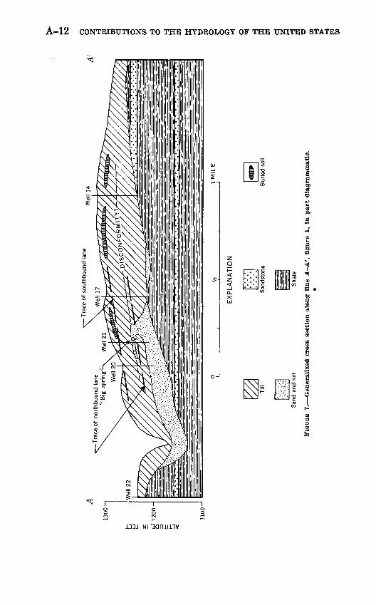
riprapped.-----_--__----------__-----------_------_--- 55. Sandstone unit exposed in ravine below the spring___________ 76. Map of "big spring" area showing contours on bedrock surface. 97. Generalized cross section-________________________________ 128. Map of "big spring" area showing contours on water table____ 14
TABLES
TABLE 1. Records of wells in the "big spring" area_____-_______-_-_-_- 162. Drillers' logs of wells in the "big spring" area._______________ 17
in

CONTRIBUTIONS TO THE HYDROLOGY OF THE UNITED STATES
HYDROGEOLOGY OF A SPRING IN A GLACIAL TERRANE NEAR ASHLAND, OHIO
By STANLEY E. NORRIS
ABSTRACT
In November 1958, near Ashland, Ohio, a spring having a discharge of about 165 gallons per minute was opened by a power shovel during construction of Interstate Route 71. The spring is on the side of a small tributary valley, a little below the level of the upland. The water flows from a glacial outwash deposit of silt and sand that contains a minor amount of coarse gravel and is interbedded with thick till. At the spring orifice this permeable deposit may occur at a disconformity between till sheets of different age; beneath the upland immediately north and northwest of the spring the outwash lies on the bedrock. Higher on the upland, about half a mile from the spring, the deposit of silt, sand, and gravel pinches out of the stratigraphic sequence, and thin till generally overlies the bedrock.
The silt, sand, and gravel, together with the underlying or closely associated sandstone and shale bedrock, constitute an important aquifer which extends over a large area. The discharge from the spring, which is replenished by drainage from the overlying till, lowered the water table from 1 to 5 feet in an area of approximately 0.7 square mile during the period November 1958 to July 1959.
The sustained large discharge of the spring occurs in what is commonly considered a water-short area; it shows vividly that large quantities of water can be transmitted through glacial materials of generally low permeability.
INTRODUCTION
About the middle of November 1958, construction of Interstate Koute 71 (called locally the North-South Freeway) was temporarily halted in the vicinity of Ashland, Ohio, when excavators, making a deep cut in glacial till, opened a large spring on the northwest side of the cut. Water from the spring, which highway engineers esti mated flowed at the rate of 165 gpm (gallons per minute), saturated the cut over a distance of several hundred feet and halted grading operations in that area until the flow was controlled. Unsuccessful attempts to stop the flow were made by bulldozing earth over the ori-
A-l

A-2 CONTRIBUTIONS TO THE HYDROLOGY OF THE UNITED STATES
fice. When this failed, the water was diverted into an underdrain through which it discharges into a small tributary valley. The spring flowed continuously through the summer of 1959, and when last observed, in late 1959, the flow appeared nearly as large as when it was estimated by highway engineers.
Such a large flow occurring in what generally is thought of as a poor area for development of wells received much local attention; the origin of the spring became also a matter of scientific interest, not only because of its high discharge, but also because the geologic and hydrologic features to which it is due probably occur in similar combination in other areas where large ground-water supplies gener ally are difficult to obtain. The spring is important locally in the movement of ground water and indicates that large quantities of water can be transmitted through glacial materials of generally low permeability.
The investigation on which this report is based was made as part of the state-wide cooperative water-resources program of the U.S. Geological Survey and the Division of Water, Ohio Department of Natural Resources. Field data were collected in the summer of 1959 and these were supplemented by drillers' logs from the files of the Ohio Divisions of Water and of Geological Survey. The writer is in debted to J. J. Schmidt of the Ohio Division of Water and Stephen DeVol of the Ohio Department of Highways for data on the geology of the spring area. Mr. Schmidt made helpful suggestions relative to the origin of the spring, as did G. W. White and J. L. Kau of the U.S. Geological Survey.
GEOGRAPHY
SITE OF THE SPUING
The "big spring," as it is known both to local residents and to the highway engineers who were faced with the problem of its control, is 4^/2 miles southwest of the center of Ashland, in the NE^NE^ sec. 2, T. 23 N., R. 17 W., Mifflin Township, Ashland County, Ohio, in the glaciated Allegheny Mountain section of the Appalachian Pla teaus physiographic province. The altitude of the upland in the vicinity of the spring is a little more than 1,300 feet, about 300 feet higher than the bottom of the nearby valley of the Black Fork of the Mohican River, the principal stream in the area. The upland sur face is gentle to moderately rolling; the strongest relief in the vicinity of the spring is in a 2- to 3-mile-wide band along the Black Fork where the spurs and ridges of the strongly dissected bedrock have been only partly covered by glacial deposits. Minor postglacial dissection by short, steep tributary streams also has taken place. The spring is

HYDROGEOLOGY OF A SPRING NEAR ASHLAND, OHIO A-3
near the head of one of these tributaries, at an altitude of 1,244 feet, about 70 feet below the highest point on the adjacent upland (figs. 1 and 2).
When the spring was opened, most of the water issued at the main orifice; however, considerable seepage occurred elsewhere along the
R. 16 W.
CONTOUR INTERVAL 40 FEET DATUM IS MEAN SEA LEVEL
Topography from U. S. Geological Survey Ashland quadrangle
EXPLANATION
o? Location of well or wejls listed in table 1
Geologic cross section shown on figure 7
FIGURE 1. 'Topographic map of the "big spring" area near Ashland, Ohio.

A-4 CONTRIBUTIONS TO THE HYDROLOGY OF THE UNITED STATES
FIGURE 2. The "big spring" near Ashland, Ohio, looking west across northbound lane of Interstate Route 71. Arrow points to spring.
highway cut, and saturated a sizeable area. At the time of the writer's first visit in June 1959, before grading operations had been completed, nearly all the flow appeared to come from the main orifice. The orifice was poorly defined; the water issued from the till at several places and wet an area about 20 feet wide (fig. 3). The main flow came from a 1^-inch-diameter pipe which had been driven into the place of the strongest discharge, and the pipe thus served as the main orifice. Water was discharged from the pipe, which is not visible in figure 3, at a point about 5 feet above grade level on the northwest side of the northbound lane of the new high way. When the slopes of the cut were graded the pipe was removed and the orifice was riprapped with large stones that restricted the flow to a small zone (fig. 4). The northbound and southbound high way lanes are separated in the spring area, their respective center lines being about 220 feet apart. At the spring the southbound lane is about 30 feet higher than the northbound lane, and consequently most of the water discharged at the spring flows under the south bound lane (fig. 7).

HYDROGEOLOGY OF A SPRING NEAR ASHLAND, OHIO A-5
FIGURE 3. 'The "big spring" as it looked before the sides of the cut were graded.
FIGURE 4. .Orifice of the "big spring" after the sides of the cut were graded and riprapped.
603288 O 61 2

A-6 CONTRIBUTIONS TO THE HYDROLOGY OF THE UNITED STATES
GROUND-WATER SUPPLY IN THE AREA
Until recent years when drilled wells became fairly common, most rural water supplies in the Ashland area were from shallow dug wells, cisterns arid, in a few places, springs. Today the majority of farms have drilled wells. Some of these wells supply all the water needed, but some supply only enough water for household purposes and dug wells may be used for stock. A few farms and suburban homes still use dug wells exclusively as their source of water supply, or augment them, especially in time of drought, with cisterns.
Typical dug wells range in depth from 15 to 25 feet, and many of them terminate in sand and gravel deposits, which either lie on the bedrock or occur as layers or lenses enclosed within the glacial till. The drilled wells generally range from 60 to 125 feet in depth and terminate in sand and gravel near the bedrock surface, or they may penetrate the uppermost few feet of the bedrock. Most drilled wells are equipped with deep-well pump and pressure systems and yield 4 to 6 gpm. Most of the dug wells are equipped with hand pumps of small capacity. No wells having yields substantially larger than that required for household and general farm use have been drilled in the immediate area of the "big spring."
GEOLOGY
CONSOLIDATED ROCKS (BEDROCK) OF MISSISSIPPIAN AGE
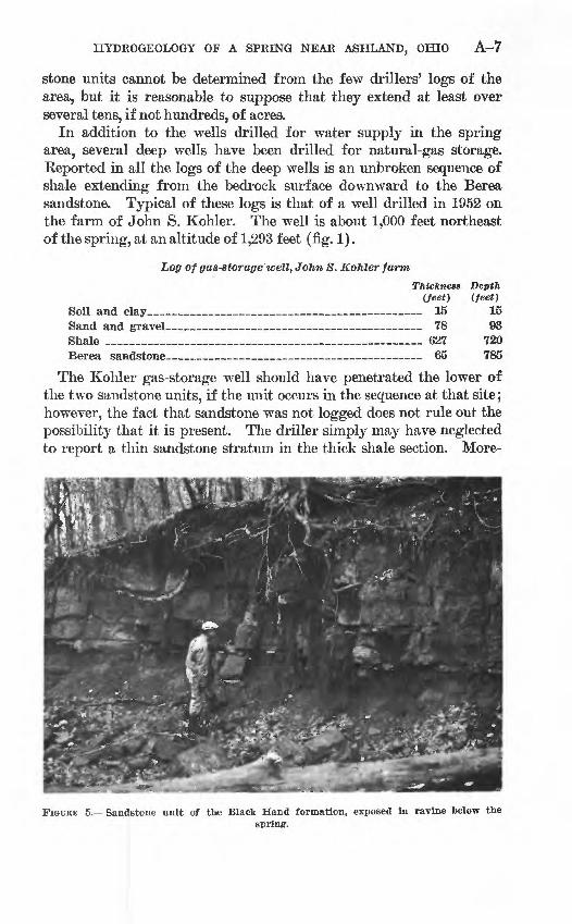
The consolidated rocks in the spring area belong to the Black Hand formation of Early Mississippian age, which ranges laterally in Ohio from sandstone to shale. In the Ashland area the rocks of the Black Hand formation were deposited as a delta, and lateral variations in their lithologic character are abrupt. In the vicinity of the spring the Black Hand consists principally of shale, but some sandstone units occur. In the cut made for the new highway, 300 to 400 feet southwest of the spring and about 10 feet lower than the orifice, about 20 feet of thin-bedded fine-grained sandstone, interbedded with shale, is exposed. Shale is exposed generally in the lower parts of two small ravines that head near the spring; however, in one of these ravines, at altitude about 1,150 feet, another sandstone unit is exposed. This lower unit (fig. 5) consists of about 8 feet of thickly bedded, blocky, somewhat friable sandstone. Both of the exposed sandstone units are probably capable of transmitting water at rates sufficient to sustain home or farm wells. The upper sandstone immediately underlies the glacial drift in parts of the upland near the spring and probably is the source of water to several wells which are reported by their owners to be dug to the top of the bedrock. The area! extent of the sand-
HYDROGEOLOGY OF A SPRING NEAR ASHLAND, OHIO A-7
stone units cannot be determined from the few drillers' logs of the area, but it is reasonable to suppose that they extend at least over several tens, if not hundreds, of acres.
In addition to the wells drilled for water supply in the spring area, several deep wells have been drilled for natural-gas storage. Keported in all the logs of the deep wells is an unbroken sequence of shale extending from the bedrock surface downward to the Berea sandstone. Typical of these logs is that of a well drilled in 1952 on the farm of John S. Kohler. The well is about 1,000 feet northeast of the spring, at an altitude of 1,293 feet (fig. 1).
Log of gas-storage well, John 8. Kohler farmThickness Depth
(feet) (feet)Soil and clay_____________________________ 15 15Sand and gravel____________________________ 78 93Shale _________________________________ 627 720Berea sandstone_____ ___________ - 65 785
The Kohler gas-storage well should have penetrated the lower of the two sandstone units, if the unit occurs in the sequence at that site; however, the fact that sandstone was not logged does not rule out the possibility that it is present. The driller simply may have neglected to report a thin sandstone stratum in the thick shale section. More-
FIGUEB 5. Sandstone unit of the Black Hand formation, exposed in ravine below thespring.

A-8 CONTRIBUTIONS TO THE HYDROLOGY OF THE UNITED STATES
over, this log seems in error in showing such a thick sand and gravel section above the bedrock. Data from other wells and surface ex posures indicate that the unconsolidated deposits in that area consist chiefly of glacial till.
UNCONSOLIDATED DEPOSITS (GLACIAL DRIFT) OP PLEISTOCENE AGE
In preglacial times the consolidated rocks in the Ashland area were eroded by streams that carved a system of steep, narrow valleys. This pre-Pleistocene stream system was similar in size and direction of flow to the modern drainage system, and the courses of the modern streams coincide generally with those of the preglacial valleys. Figure 4 shows that the "big spring" is located near the head of a small preglacial stream system whose main stem is south of the spring and roughly parallel to the new highway. The spring is on the north side of a formerly southwest-flowing tributary that probably rose, as does its modern counterpart, on the nearby upland to the north and east.
The contour map of the bedrock surface (fig. 6), which is based largely on the records of wells, shows that the preglacial streams had cut their valleys to about 1,100 feet altitude in the general area of the spring. The altitude of the bedrock at the spring, as computed from the map, is about 1,160 feet; the depth to bedrock, therefore, is about 80 feet.
Glaciers advanced and retreated several times over the Ashland area and generally deposited till, a compact mixture of clay, silt, sand, and stones, which in places is interbedded with or underlain by silt, sand, and gravel. Some of the till deposits have been differentiated and related to specific glacial episodes. Near Ashland, G. W. White, (1959, oral communication), recognized at least two tills, each trace able over wide areas as distinct stratigraphic units, which were deposited during successive ice advances. These two tills are sepa rated generally by remnants of a soil which was formed during an interval between the glacial advances, when the area was free of ice.
The buried soil, which is evident in the Ashland area as a reddish streak in fresh drift exposures, was discernible at several places along the new highway while construction was in progress. It was briefly exposed near the spring, in June of 1959, near the top of the highway cut, about 25 feet above the orifice. Over wide areas the buried soil is absent, having been removed by abrasion of the ice which deposited the upper till. Locally, though not in the immediate area of the spring, a thin, poorly sorted gravel lies at the contact of the buried soil and the overlying till.

HYDROGEOLOGY OF A SPRING NEAR ASHLAND, OHIO A-9
The buried soil is clear evidence of a widespread disconformity in the glacial sequence. Other disconformities, not so clearly marked, occur in the till sequence, below the buried soil. Permeable zones formed by silt, soil, and gravel occur at some of these disconformities. The till at the "big spring" was not exposed clearly enough to show
R. 17 W
Location of wellTop number refers to we/1 listed in table
1 Middle number gives depth to bed rock. Plus sign indicates that bedrock was not reached. Bottom number is altitude of bedrock
Location of bedrock exposure
Axes of buried valleys
CONTOUR INTERVAL 50 FEET DATUM IS MEAN SEA LEVELTopography from U S Geologica
Survey Ashland quadrangle
FIQCKB 6. Map of the "big spring" area showing contours on bedrock surface.

A-10 CONTRIBUTIONS TO THE HYDROLOGY OF THE UNITED STATES
definitely that the permeable zone from which the spring discharges occurs at a disconformity, though evidence from nearby areas strongly suggests this. White (1959, written communication) stated:In Richland County several miles southwest of the "big spring," deep cuts for the superhighway exposed a persistent layer of silt, sand, and gravel from a few inches to ten feet or more in thickness. This stratum appears to separate two tills, which lie below a buried soil correlated with that lying 25 feet or so above the "big spring." It is therefore probable that the aquifer here described also occurs at a disconformity at a similar stratigraphic position.
The sustained high discharge of the spring shows that the aquifer that feeds it is of wide areal extent. The same evidence indicates that the aquifer is of fairly high permeability and of considerable thickness.
CHARACTER OF THE AQUIFER THAT SUSTAINS THE SPRING
The "big spring" flows from a permeable zone in the lower of the two till units recognized by White. When first observed by the writer, several months after the cut had been roughly graded (fig. 3), the water issued principally from a 4-inch-thick bed of sand and gravel which formed a local discontinuity in an otherwise homogeneous- appearing deposit of brownish-gray till. This sand and gravel stratum appeared to descend sharply into the till, and the water to rise to the level of the discharge point.
The gravel fraction of the material exposed at the orifice consisted of poorly sorted angular to subangular pebbles, which apparently have been washed from the surrounding till. J. J. Schmidt (written communication, 1960), who observed the spring soon after the cut was made, said the flow originally was from a permeable zone formed entirely of fine sand and silt and containing no gravel. Schmidt further described the flow as coming from "blue till, perhaps 3 inches below the contact with the upper yellow till"; his description indicates that the orifice occurs near the top of the unoxidized zone in the lower till unit.
Test borings made by highway engineers indicate that the sand and silt formerly exposed at the orifice is part of a much larger deposit that underlies the highway at shallow depth in the vicinity of the spring. Soon after the spring was opened, the engineers sunk 13 bore holes on and along the highway in the immediate vicinity of the spring. The depth of the bore holes ranged from 5 to 41 feet; however, because the holes either were located well above the spring on the highway embank ment or because drilling ceased whenever water-bearing silt or sand and gravel was penetrated, none reached to more than a few feet below the level of the orifice. Coarse sand and gravel were reported from only two of the test holes; in one of these holes water rose abruptly, when the sand and gravel unit was reached, to an altitude of 1,242 feet, about 2 feet below the level of the orifice. The other test borings

HYDROGEOLOGY OF A SPRING NEAR ASHLAND, OHIO A-ll
terminated in what the highway engineers called "silt" or "sandy silt." According to Schmidt, who was present during the test boring, this material was homogeneous in appearance, was uniform in com position, and probably represented a stratified deposit, similar to that exposed at the orifice.
The sandy silt that underlies the highway in the vicinity of the spring is, in all probability, part of the fine sand and silt deposit formerly exposed at the orifice (fig. 7). Had the highway cut been but a few feet deeper, the silt would have been exposed at grade level and the main discharge no doubt would have been from there, rather than from the present orifice. As it was, water in the underlying silt caused what the engineers termed "sand boils" to occur for 300 feet along the grade northeast of the spring. The sand boils were prob ably caused by hydrostatic pressure that forced the water in the silt upward through a thin cover of till.
A study of well records from the area north of the spring shows that the sand and silt unit is not of widespread distribution; it appears to be confined principally to a shallow depression in the bedrock, the center of which lies a few hundred feet northwest of the orifice. Logs of wells 16, 20, and 21 (table 2) report sand or sand and gravel at altitudes ranging from 1,215 to 1,236 feet, not far beneath the altitude of the'orifice. Sand and gravel were not reported from well 17, drilled at the John Kohler residence about 1,000 feet northeast of the spring, nor from wells 9,13, and 14, drilled farther from the spring in the same general area. Furthermore, as stated previously, the report that sand and gravel occurred between depths of 15 and 93 feet at the site of the gas-storage well drilled on the John Kohler farm is believed in error; the sand and gravel reported in that well probably are stony till. However, even if a sand and gravel deposit as thick as reported does occur at the site of the gas-storage well, such occurrence does not appreciably alter the evidence which points to a restricted deposit of stratified material in the vicinity of the spring. This stratified deposit probably originated as glacial outwash laid down by melt- water confined to a local basin. Such a basin may have been formed by a tongue of ice damming the tributary bedrock valley over which the spring occurs.
If the silt, sand, and gravel deposit is relatively small in areal extent, it can constitute only a small part of the aquifer that sustains the spring; the whole aquifer probably includes the upper part of the bedrock. The silt, sand, and gravel unit lies on the bedrock in the area immediately north and northwest of the spring where it evidently received much or most of the water discharged at the orifice. It acts very much as a farmer's field-drain tile in collecting and con ducting water from a large area to the orifice.
A-12 CONTRIBUTIONS TO THE HYDROLOGY OF THE UNITED STATES
133J NI 'aaniinv
HYDROGEOLOGY OF A SPRING NEAR ASHLAND, OHIO A-13
HYDROLOGY OF THE "BIG SPRING"
The "big spring" represents a conspicuous point of discharge of an aquifier, of wide areal extent, that consists mostly of silt and sand part of which is exposed at the orifice and the upper part of the shale and sandstone bedrock. Before the spring was opened, the aquifer probably discharged naturally in the same area through springs and seeps, though at a much slower rate. Opening the spring was like opening wider a valve in a water- supply system, the result being to increase the rate of natural discharge. This discharge af fected ground-water levels over a wide area, as shown by measure ments made July 7-8, 1959, in 19 wells in the vicinity of the spring. The water-table contour map (fig. 8), which is based on these measure ments, reveals an elongated cone of depression having its apex at the spring and extending nearly a mile to the north and northeast. The cone of depression underlies an area of approximately 0.7 square mile.
It may at first seem paradoxical that the major development of the cone of depression occurred in the area north and northeast of the spring, rather than in the area to the north and northwest where the silt, sand, and gravel deposit is thickest. The principal reason for this seeming contradiction is that the tei'rane is highest north and northeast of the spring, and the slope of the land generally determines the direction of natural drainage in the area. The slope of the water table, which is governed by the altitude o:E the outlet at the orifice, is relatively steep in that direction and, consequently, most of the flow at the spring is sustained by drainage from the higher areas to the north and northeast. The ground water flows generally southwest- ward into the buried silt, sand, and gravel deposit through which it is conducted, probably with little additional head loss, to the orifice. This deposit functions as a detention reservoir in stabilizing the discharge from the spring.
Water-table conditions prevail generally in upland areas where thin till overlies the bedrock, and artesian conditions prevail in the areas where thick till overlies the silt, sand., and gravel deposit. Most of the wells measured in the vicinity of the spring are shallow water- table wells dug in the till. The cone of depression thus indicates the area where the greatest amount of head-lowering due to leakage from the till takes place.
The amount of lowering of the ground-water level is not uniform in the area underlain by the cone of depression, and the water level in wells near the spring, as would be expected, declines much more than that in wells near the periphery of the cone of depression. For example, measurements made at the beginning and at the end of a

A-14 CONTRIBUTIONS TO THE HYDROLOGY OF THE UNITED STATES
99-day period between May 13 and August 20, 1959, in three wells located near the axis of the cone of depression, about three-fourths mile north of the spring, show that the water table declined 4 feet in well 9 and more than 7 feet in wells 10 and 12. Both the latter wells were dry at the time of the final measurement, on August 20,
R. 17 W R.16W.
CONTOUR INTERVAL 10 FEET DATUM IS MEAN SEA LEVEL
Topography from U S Geological Survey Ashland quadrangle
EXPLANATION
1128 +
Location of wellTop number refers to well listed in tobli
1. Middle number gives depth to wate
Plus sign indicates well was dry. Eotton number is altitude of water table
Dashed line encloses area affected by spring on July 7-8, 1959
FIGURE 8. Map of the "big spring" area showing contours on water table, based on measurements made July 7-8, 1959.

HYDROGEOLOGY OF A SPRING NEAR ASHLAND, OHIO A-15
1959, and the actual amount of lowering of the ground-water level at those sites is not known. According to the owners, these wells had never gone dry before during their observations which extended back over many years.
In the period May 13 to August 20 the average decline in ground- water levels in the 0.7 square mile area underlain by the cone of depression would have been 1.1 feet if a total outflow at the spring of approximately 23 million gallons and a specific yield of 15 percent for the sediments being drained are assumed.
Of course not all the lowering of the ground-water level in the area was due to the discharge at the spring. The period of observa tion was one of little or no recharge in 'Ohio, during which ground- water levels would normally decline generally. Records maintained by the Ohio Division of Water show that the water levels in four shal low wells, widely scattered but nevertheless typical of the wells in the spring area, declined from 2 to about 6.5 feet in the period May 13 to August 20. The average decline in these four observation wells over the specified period was 2.6 feet. On the basis of these com parisons, it seems probable that the discharge at the spring has lowered water levels 5 or more feet in some wells.
CONCLUSIONS
Deposits of silt or sand and gravel commonly occur in till, many of them at disconformities between till sheets of different ages. This relationship in northeastern Ohio has been described by White (1960), in east-central Indiana by Gamble (1958, p. 37), and in other areas by other geologists. Buried sand and gravel deposits that originated as an outwash plain may be several tens of feet thick and may under lie several square miles, as they do in parts of western and central Ohio (Goldthwait, R. P., 1948, p. 34; 1950, p. 18; Norris, 1959, p. 343). Such deposits that originated as valley-train deposits and that were laid down in definite channels extending away from the ice front are correspondingly linear in shape and may be highly variable in thickness. These buried sand and gravel deposits con stitute zones of high permeability in the glacial deposits, and are highly important in ground-water circulatory systems in areas of glacial terrane. They function much as do open joints and solution cavities in limestone in conducting water through an otherwise poorly permeable medium.
The "big spring" illustrates the special effects on the regional hydrology of a permeable deposit bedded in till. Here the deposit functions principally as a conduit through which water from the more extensive bedrock part of the aquifer is discharged to the sur-

A-16 CONTRIBUTIONS TO THE HYDROLOGY OF THE UNITED STATES
face. The large quantity of water transmitted indicates the potential importance of many such interbedded deposits as sources of ground water in areas of glacial terrane.
REFERENCES
Gamble, E. E., 1958, Descriptions and interpretations of some Pleistocene sec tions in Wayne County, Indiana: Richmond, Earlham College Sci. Bull. 3, 41 p.
Goldthwait, R. P., 1948, Glacial geology in Water resources of Montgomery County, Ohio: Ohio Water Res. Board Bull. 12, p. 32-36.
1950, Wisconsin glacial deposits, in The water resources of Greene County, Ohio: Ohio Dept. Nat. Res., Div. Water Bull. 19, p. 13-19.
Norris, S. E., Buried topography and its relation to an important aquifer in Franklin County, Ohio: Ohio Jour. Sci., v. 59, p. 341-343.
White, G. W., 1960, Classification of Wisconsin glacial deposits in northeastern Ohio: U.S. Geol. Survey Bull. 1121-A.
TABLE 1. Records of wells in the "big spring" area
Well
1 2 3 4 5 6 7 8
>9 10 11 12
113 U4
15 116 117
18 19
120 121
22 123
24
Owner
Mrs. Hiller... __ .. ...
Chester Swank __ .. ...-do..... ... Dale Dohner.. ........ C. E. Roland .........
Jas. Van Bremen ...... A. H. Wickham .......
Henry Ohl ............
-do . John Kohler.-.. ......
F. W. White. __ ....
D. Brandt ______J. C. Shannon .........
Altitude above sea level (feet)
1,282 1,282 1,275 1,280 1,280 1,260 1,280 1,285 1,298 1,300 1,305 1,2981,300 1,302 1,282 1,283 1,285 1,3081,250 1,265 1,285 1,235 1,282 1,282
Type of well
Dug .. do __ .... ..... do... ...... do .. -do. ........ do... ... ... Drilled.. Dag...... .Drilled.... .Dug... do..... - -do Drilled -do Dug..... DrilloH
-do .do .... .Dug..... .Drilled.. do
Drilled .
Depth of well (feet)
18 16 16 26 20 20 32 21 43 25 28 18 88 93 19 87
122 67 17 98 76 21
198 25
Depth to which well is cased (feet)
18 16 16 26 20 20 32 21 30 25 28 18 42 62 19 87
118 ?
17 98 76 21
198 25
Water level
Feet below surface
15.6 7.6 9.2
15.5 18.2 8.6
14.9 8.7
28.2 24.0 Dry 13.8 30.2 34.1 8.0
12.5
16.4 47.5 16.5
Date of measure
ment
7-8-59 7-8-59 7-8-59 7-8-59 7-8-59 7-8-59 7-8-59 7-8-59 7-7-59 7-7-597-7-59 7-7-59 7-7-59 7-7-59 7-8-59
7-8-59
7-8-59 7-8-59 7-8-59
> Log given in table 2.

HYDROGEOLOGY OF A SPRING NEAR ASHLAND, OHIO A-17
TABLE 2. Drillers' logs of wells in the "big spring" area[Wells described in table 1, located in fig. 1]
Thick- nets Depth
Well 9 (feet) (feet)Clay -_-______-_________-___________-_-_-_---__-__-___ 11 11Clay and gravel_---_-_____-___-_-___-_____-___-_________-_ 14 25Gray clay..__________________________.___ 5 30Gray shale (water at 37 ft)_-_-_---_-____-__------_--___-_ 13 43
Well 13Clay______________._______._--___-___----_--_--__._-_-- 42 42Rock..__________________._.._____.______ 46 88
Well 14 Clay.....________________________________________________ 62 62Rock____________________.______________ 31 93
Well 16Clay...-._-_....._...__..__._.._._......_...._._._...... 6 6Gravel»_._._...__..._.__._.__.._..___.__....__..._.._.._ 12 18Gray sand--_-__-_--_____-_-_-_--__..___________._-_____--. 47 65Gravel._________________..______________ 15 80Gray sand.___-________.___._..____________-.-__- 6 86Water sand (coarse)________________________________________ 1 87
Well 17Clay__.....-______.__ __ ..__ _ ___ 118 118Rock______________________________.______________________ 4 122
Well 20Clay __ _ _ __ .. . _ -- 4 4Clay and gravel._____________-_--_-.___-__-_____--_----_-_ 45 49Sand_______.___________..______________ 6 55Claysand__________________________________ 40 95Gravel..... _ ____ _ _ __________ 3 98
Well 21 Clay and gravel______-________-_---.--_--.---.----------_---- 70 70White sand________________. ______ _ _______ 6 76
Well 23» Clay--_--__--__________-_---_------_--_---_--_-__-------- 45 45
euicksand . _._ __. . _ ___ ..._______________-__ 150 195 ravel......____-__---_-___---_..-----_--_---_-_------ 3 198» Possibly till.1 Log given by Mr. Shannon from memory.
O