hydrogen/methanol production in a novel multifunctional reactor with in situ ...
TRANSCRIPT

Hydrogen/methanol production in a novelmultifunctional reactor with in situ adsorption:modeling and optimizationM. Bayat, M. Hamidi, Z. Dehghani, M. R. Rahimpour*,† and A. Shariati
Department of Chemical Engineering, School of Chemical and Petroleum Engineering, Shiraz University, Shiraz, Iran
SUMMARY
This work proposes a novel multifunctional reactor for simultaneous production of hydrogen and methanol in which zeolite 4Ais considered as water adsorbent. For this purpose, in the exothermic side of the proposed configuration, a gas-flowing solid-fixed bed reactor (GFSFBR) is used. The remarkable advantage of GFSFBR over the conventional sorption-enhanced reactionprocess is the continuous adsorbent regeneration in this novel reactor. MR takes the advantages of adsorption and couple tech-nique simultaneously. The new configuration is designed as a double pipe reactor where highly exothermic methanol synthesisreactions in the exothermic side are coupled with dehydrogenation of cyclohexane. A one-dimensional, steady-state heteroge-neous model is used to simulate the proposed reactor configuration. Simulation result demonstrates that selective adsorption ofwater in the exothermic side leads to 22.5%, 9.85% and 7.1% enhancement in methanol, benzene and hydrogen production,respectively, compared with the zero solid mass flux condition. Subsequently, the aforementioned reactor is optimized usingdifferential evolution algorithm to maximize the hydrogen mole fraction in the endothermic side as well as the methanol yieldin the exothermic side. Copyright © 2013 John Wiley & Sons, Ltd.
KEY WORDS
hydrogen production; methanol synthesis; zeolite 4A; water vapor adsorption; gas-flowing solids-fixed bed reactor; optimization;recuperative coupling
Correspondence
*M. R. Rahimpour, Department of Chemical Engineering, School of Chemical and Petroleum Engineering, Shiraz University, Shiraz71345, Iran.†E-mail: [email protected]
Received 16 April 2013; Revised 5 July 2013; Accepted 7 July 2013
1. INTRODUCTION
Most of the energy used today is produced from fossilfuels, which are nonrenewable energy sources. Neverthe-less, the world’s dependence on fossil fuels as an energysource leads to serious environmental problems such asthe depletion of natural resources, greenhouse gas emis-sions and air pollution. Because of these issues, it seemsvital to search for alternative methods to produce energy.
Hydrogen is a promising, effective and clean energycarrier. It can be prepared in several different ways, such asdehydrogenation, steam-methane reforming, thermo chemi-cal water splitting and high temperature electrolysis [1].Between these methods, dehydrogenation is an attractivechoice for hydrogen production because of its essentiallyzero carbon dioxide impact, resulting in safe contributionsto the environment [2].
Methanol is a basic building block for hundreds ofessential chemical commodities and is a transportation
fuel, a hydrogen carrier for fuel cell technologies, and anefficient fuel for electric power generation. It is one ofthe cleanest burning fuels and versatile enough to be usedalmost anywhere. Utilization of methanol in current-technology vehicles has some distinct advantages and dis-advantages. It has a higher octane rating than gasoline.Methanol’s high heat of vaporization results in lower peakflame temperatures than gasoline and lower nitrogen oxideemissions. Its greater tolerance to lean combustion higherair-to-fuel equivalence ratio results in generally loweroverall emissions and higher energy efficiency. However,energy density of methanol is about half that of gasoline,reducing the range a vehicle can travel on an equivalenttank of fuel [3].
Numerous studies have been conducted in an attempt toimprove the efficiency of industrial methanol synthesisreactor. In 2009, Khademi et al. presented a membranethermally coupled reactor consist of three sides: methanolsynthesis, cyclohexane dehydrogenation and hydrogen
INTERNATIONAL JOURNAL OF ENERGY RESEARCHInt. J. Energy Res. (2013)
Published online in Wiley Online Library (wileyonlinelibrary.com). DOI: 10.1002/er.3092
Copyright © 2013 John Wiley & Sons, Ltd.

production [4]. Methanol synthesis takes place in theexothermic side and provides the necessary heat for theendothermic dehydrogenation of cyclohexane reaction.Afterwards, they optimized this coupled configuration bythe DE method [5] to achieve the optimal operating condi-tions and enhance methanol, benzene and hydrogenproduction rates in a membrane thermally coupled reactor.Rezaie et al. presented results of heterogeneous model withcomparison to homogeneous model through a dynamicsimulation that similar predictions were reported [6].Rahimpour and Pourazadi compared hydrogen andmethanol production rates in a thermally coupled mem-brane reactor for co-current and counter-current flows [7].Recently, Bayat et al. [8] proposed a steady-state mathe-matical model of a gas-flowing solid-fixed bed reactor(GFSFBR) for methanol synthesis and a multi-objectiveoptimization of GFSFBR operating conditions with thepurpose of maximizing methanol production rate andselectivity using NSGA-II.
In this work, the considered process intensification ideawould be to introduce a third phase (flowing solids) in theexothermic side, which are selective adsorbents for H2O.In this type of equipment, fine solid particles (adsorbents)and gas flow counter-currently (or co-currently) throughthe column packed with other solid phase (catalysts). Theremarkable advantage of this system (GFSFBR) over theconventional sorption-enhanced process is the continuousadsorption-regeneration system of GFSFBR. The discon-tinuous operation of the sorption-enhanced reactionprocess is the main problem because at the equilibriumof the adsorbent, the separation effect is lost, and as aconsequence, a periodic regeneration of the adsorbentis needed.
Introducing an additional flowing phase (the adsorbentsolids) to the gas phase changes the transport characteris-tics of the catalytic packed bed reactor considerably. Theflow pattern is more complicated because of the presenceof the flowing solids and their contact with the gas andpacking elements. Consequently, a GFSFBR is operation-ally more demanding than a classical reactor [9].
GFSFBRs can be considered as two-phase or three-phase systems [10]. In this paper, a model of three-phase system is proposed, and the third active phaseis zeolite 4A, which is applied as the adsorbent. Zeolite4A is a solid particle, with the composition of Na12(Si12Al12O48).27H2O. It has high adsorption affinityand capacity for water, which makes it interesting inwater removal or separation [11].
GFSFBR can be used as equipment for a wide range ofprocesses owing to favorable properties such as a lowpressure drop, high mass and heat transfer rates, low axialdispersion in both flowing phases and continuous adsorp-tion-regeneration system. The latter one is the mainadvantage of GFSFBR over the other sorption-enhancedreaction processes. The regeneration of zeolite 4A isbased on desorption of water vapor. The dehydration ofzeolites is usually conducted under vacuum, or in a flowof the carrier gas, with a simultaneous raising of the
temperature to 300–400ºC [12]. The thermal stability ofzeolite 4A crystals is rather good and only above 1073K, the change of its structure occurs, accompanied by areduced water capacity [11].
The concept of contacting gas and fine solid particles(flowing solids) inside a packed bed was patented nearly60 years ago [13]. Kuczynski et al. [14] have investigatedan experimental study of methanol synthesis in a counter-current gas-solid-solid trickle flow reactor. The resultsshow that the reactant’s conversion was higher when theproduct was removed from the reactor. In 1988, the inten-sified process was compared with the conventional metha-nol synthesis in an optimized Lurgi process [15]. Becauseof the reduction in recirculation rate and pressure drop inthe reactor, a significant energy saving in the synthesisloop was reported. A steady-state mathematical model ofammonia synthesis with in situ adsorption in a co-currentGFSFBR has been developed. The simulation results showthat the conversion stays higher than those in the classicalreactor even if much lower temperatures and pressures areused [16]. An isothermal, unsteady-state model has beendeveloped by Iliuta et al. [17] to evaluate the performanceof a sorption-enhanced DME synthesis reactor. The simu-lated results indicate that, under water removal conditions,the methanol yield and DME yield and selectivity arefavored, and the fraction of unconverted methanol isreduced.
In the proposed reactor, the solids stream entering thereactor should be heated up to the reaction temperature;thus, a solid preheater is needed to be installed above thereactor section. Besides the heating costs, investment costsin materials that withstand the high pressures of operationincreases with respect to the conventional reactor (CR).In addition, the solid regenerator, which usually requiresthe high investment and operational costs such as the otherregeneration processes adds to the expenses.
Despite the above-mentioned costs, the reactor haseconomic benefits. Because the capacity of the methanolsynthesis plant is usually very high, even a small enhance-ment in the plant operation can generate major income. Inthis work, the novel reactor boosts methanol, hydrogen andbenzene compared with the CR.
In this paper, the application of multifunctional reactor(MR) for simultaneous production of hydrogen andmethanol is investigated by using mathematical modelingand optimization strategies. The motivation is to combinethe energy efficient concept of the coupling of endother-mic-exothermic reactions and introducing an additionalflowing phase (the adsorbent solids) to the exothermicside of the novel reactor. The underlying goals of thiswork are to develop a steady-state, one-dimensionalmodel for MR to enhance methanol synthesis andcyclohexane dehydrogenation. In the exothermic side ofproposed configuration, a gas-flowing solid-fixed bedreactor (GFSFBR) is used. The operating condition ofan actual fixed-bed reactor is considered as a basis forsimulating the MR. Afterward, the differential evolutionmethod, as a strong and powerful optimization method
Multifunctional sorption-enhanced methanol reactorM. Bayat et al.
Int. J. Energy Res. (2013) © 2013 John Wiley & Sons, Ltd.DOI: 10.1002/er

is used to determine the optimal reactor operatingconditions for MR concept. Ultimately, the simulationand optimization results are compared with the ones inthermally coupled reactor (TCR) and CR.
2. REACTION SCHEME ANDKINETICS
2.1. Methanol synthesis
In the conversion of synthesis gas to methanol, threeoverall reactions are mainly involved: hydrogenation ofCO, hydrogenation of CO2, and reversed water-gas shiftreaction, which represented as follow:
COþ 2H2↔CH3OH ΔH298 ¼ �90:55kJ mol�1 (1)
CO2 þ 3H2↔CH3OH þ H2O ΔH298 ¼ �49:43kJ mol�1 (2)
CO2 þ H2↔COþ H2O ΔH298 ¼ þ41:12kJ mol�1 (3)
Reactions (1)–(3) are not independent, and the secondone is a linear combination of the others. In the currentstudy, the rate expressions have been selected from Graafet al. [18] with the temperature range of 200–265oC, whichis more common kinetics of methanol synthesis in indus-trial scale. The kinetics rate expressions based on Graaf’sexperiments are as follows:
r1 ¼k1KCO f COf
3=2H2
� f CH3OH= f 1=2H2KP1
� �h i1þ KCOf CO þ KCO2 f CO2
� �f 1=2H2
þ kf H2O
h i (4)
r2 ¼k2KCO2 f CO2
f 3=2H2� f CH3OHf H2O= f 3=2H2
KP2
� �h i1þ KCOf CO þ KCO2 f CO2
� �f 1=2H2
þ kf H2O
h i (5)
r3 ¼k3KCO2 f CO2
f H2� f H2Of CO=KP3
� �1þ KCOf CO þ KCO2 f CO2
� �f 1=2H2
þ kf H2O
h i (6)
The reaction rate constants, adsorption equilibriumconstants and reaction equilibrium constants, which occurin the formulation of kinetic expressions, are tabulated inTables I–III, respectively.
2.2. Benzene synthesis (dehydrogenation ofcyclohexane)
The reaction scheme for the dehydrogenation of cyclohexaneto benzene is as follows:
C6H12↔C6H6 þ 3H2 ΔH298 ¼ þ206:2kJ=mol (7)
The rate expression has been selected from Itoh [20]:
rc ¼�k KPPC=P3
H2� PB
� �1þ KBKPPC=P3
H2
� � (8)
where k, KB and KP are the reaction rate constant, theadsorption equilibrium constant for benzene and the reactionequilibrium constant, respectively, that are tabulated inTable IV. Pi is the partial pressure of component i in Pa.The range of temperature is 423–523 ºK, and the totalpressure in the reactor is maintained at 1 atm. The catalystis Pt/Al2O3 [21].
3. PROCESS DESCRIPTION
The methanol synthesis has been investigated in CR,thermally coupled reactor (TCR) and MR, particularlyMR, as will be described further.
Table I. Reaction rate constants [18].
k ¼ A exp BRT
� �A B
k1 (4.89±0.29) × 107 � 113000±300k2 (1.09±0.07) × 105 � 87500±300k3 (9.64±7.30) × 1011 � 152900±11800
Table II. Adsorption equilibrium constants [18].
K ¼ A exp BRT
� �A B
KCO (2.16±0.44) × 10�5 (46800±800)KCO2 (7.05±1.39) × 10�7 (61700±800)KH2O=KH2
1=2
� �(6.37±2.88) × 10�9 (84000±1400)
Table III. Reaction equilibrium constants [19].
KP ¼ 10A
T= Þ�BÞðð A B
KP1 5139 12.621KP2 3066 10.592KP3 �2073 �2.029
Table IV. The reaction rate constant, adsorption equilibriumconstant and reaction equilibrium constant for dehydrogenation
of cyclohexane.
k=Aexp(B/T) A B
k 0.221 �4270KB 2.03×10⁻¹⁰ 6270KP 4.89×1035 3190
Multifunctional sorption-enhanced methanol reactor M. Bayat et al.
Int. J. Energy Res. (2013) © 2013 John Wiley & Sons, Ltd.DOI: 10.1002/er
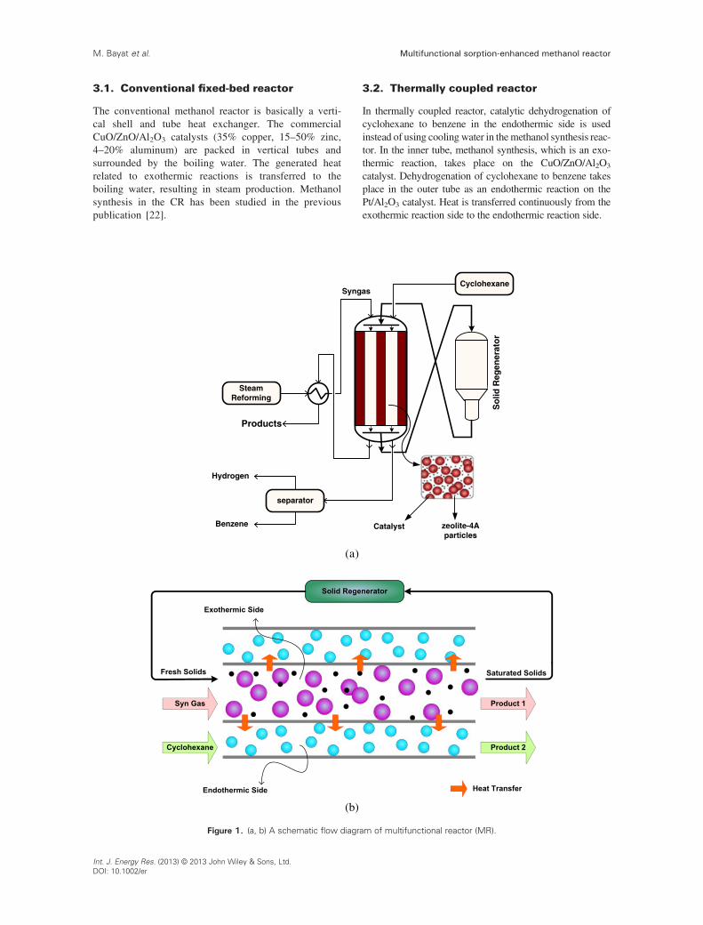
3.1. Conventional fixed-bed reactor
The conventional methanol reactor is basically a verti-cal shell and tube heat exchanger. The commercialCuO/ZnO/Al2O3 catalysts (35% copper, 15–50% zinc,4–20% aluminum) are packed in vertical tubes andsurrounded by the boiling water. The generated heatrelated to exothermic reactions is transferred to theboiling water, resulting in steam production. Methanolsynthesis in the CR has been studied in the previouspublication [22].
3.2. Thermally coupled reactor
In thermally coupled reactor, catalytic dehydrogenation ofcyclohexane to benzene in the endothermic side is usedinstead of using cooling water in the methanol synthesis reac-tor. In the inner tube, methanol synthesis, which is an exo-thermic reaction, takes place on the CuO/ZnO/Al2O3
catalyst. Dehydrogenation of cyclohexane to benzene takesplace in the outer tube as an endothermic reaction on thePt/Al2O3 catalyst. Heat is transferred continuously from theexothermic reaction side to the endothermic reaction side.
Figure 1. (a, b) A schematic flow diagram of multifunctional reactor (MR).
Multifunctional sorption-enhanced methanol reactorM. Bayat et al.
Int. J. Energy Res. (2013) © 2013 John Wiley & Sons, Ltd.DOI: 10.1002/er
3.3. Multifunctional reactor
A conceptual schematic of MR is shown in Figure 1(a).Catalytic dehydrogenation of cyclohexane to benzene isassumed to take place in the endothermic side, whereasmethanol synthesis occurs inside the exothermic side. Heatis transferred continuously from the exothermic side to theendothermic side. The exothermic side consist of flowingsolid (zeolite 4A) as adsorbent for water. The flowingsolids are continuously fed into the top of the reactor, passthrough the tube and adsorb water vapor, then removedfrom the lower end. Afterward, regenerate in the solidregenerator and subsequently fresh adsorbents are fed tothe exothermic side of the reactor again. Figure 1(b) showsan element volume of the MR.
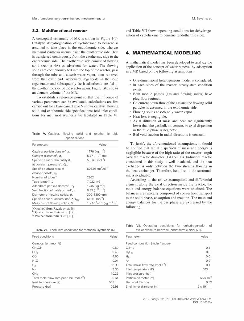
To establish a reference point so that the influence ofvarious parameters can be evaluated, calculations are firstcarried out for a base case. Table V shows catalyst, flowingsolid and exothermic side specifications; feed inlet condi-tions for methanol synthesis are tabulated in Table VI,
and Table VII shows operating conditions for dehydroge-nation of cyclohexane to benzene (endothermic side).
4. MATHEMATICAL MODELING
A mathematical model has been developed to analyze theapplication of the concept of water removal by adsorptionin a MR based on the following assumptions:
• One-dimensional heterogeneous model is considered.• In each sides of the reactor, steady-state conditionexists.
• Both mobile phases (gas and flowing solids) haveplug flow regimes.
• Co-current down-flow of the gas and the flowing solidparticles is assumed in the exothermic side.
• Flowing solids adsorb only water vapor.• Heat loss is negligible.• Axial diffusion of mass and heat are significantlylower than the gas bulk movement, so axial dispersionin the fluid phase is neglected.
• Bed void fraction in radial directions is constant.
To justify the aforementioned assumptions, it shouldbe notified that radial dispersion of mass and energy isnegligible because of the high ratio of the reactor lengthover the reactor diameter (L/D> 100). Industrial reactorconsidered in this study is well insulated, and the heatexchange is only between the two streams flowing inthe heat exchanger. Therefore, heat loss to the surround-ing is negligible.
According to the above assumptions and differentialelement along the axial direction inside the reactor, themole and energy balance equations were obtained. Thebalances are typically composed of convection, transportto the solid phase, adsorption and reaction. The mass andenergy balances for the gas phase are expressed by thefollowing:
Table V. Catalyst, flowing solid and exothermic sidespecifications.
Parameters Value
Catalyst particle densitya, ρs 1770 (kg.m-3)Catalyst diametera, ds 5.47×10⁻³ (m)Specific heat of the catalystat constant pressurea, Cps
5.0 (kJ.mol-1)
Specific surface area ofcatalyst pelleta, as
626.98 (m2.m-3)
Number of tubesa 2962Tube lengtha, L 7.022 (m)Adsorbent particle densityb, ρ′S 1245 (kg.m-3)Void fraction of catalytic beda, ε 0.39 (m3.m-3)Diameter of flowing solids, d′s 300–1300 (μm)Specific heat of adsorptionc, ΔHads 64 (kJ.mol-1)Mass flux of flowing solids, S 1×10⁻⁴–0.1 (kg.m-2.s-1)aObtained from Rezaie et al. [6].bObtained from Iliuta et al. [17].cObtained from Zhu et al. [11].
Table VI. Feed inlet conditions for methanol synthesis [6].
Feed conditions Value
Composition (mol %)CH3OH 0.50CO2 9.40CO 4.60H2O 0.04H2 65.90N2 9.30CH4 10.26Total molar flow rate per tube (mol s-1) 0.64Inlet temperature (K) 503Pressure (bar) 76.98
Table VII. Operating conditions for dehydrogenation ofcyclohexane to benzene (endothermic side) [23].
Parameter value
Feed composition (mole fraction)C2H12 0.1C6H6 0.0H2 0.0Ar 0.9Total molar flow rate (mol s-1) 0.1Inlet temperature (K) 503Inlet pressure (bar) 1Particle diameter (m) 3.55×10⁻³
Bed void fraction 0.39Shell inner diameter (m) 6×10⁻²
Multifunctional sorption-enhanced methanol reactor M. Bayat et al.
Int. J. Energy Res. (2013) © 2013 John Wiley & Sons, Ltd.DOI: 10.1002/er

� 1Ac
dFi;j
dzþ asj:cj:kgi;j ysi;j � yi;j
� �� γ:k′g:a′s:ρ′s qe � qð Þ ¼ 0
i ¼ 1; 2; 3;…;N
(9)
� 1Ac
Cpgjd FtjTgj
� �dz
þ asj:hfj: Tsj � Tgj
� �
±πDi
Ac:U Tg1 � Tg2� �� βh′f a′s Tg1 � T ′
s
� � ¼ 0
(10)
where ysi,j and yi,j are the catalyst phase and gas-phasei-component mole fraction in j side of reactor, respec-tively. In Equation (9), γ is equal to 1 for H2O compo-nent and inner tube (j = 1); it is zero for the othersituations. In Equation (10), β is equal to 1 for the innertube (j = 1) and zero for the outer tube (j = 2). Thefollowing two conservation equations are written forthe catalyst pellets:
asj:cj:kgi;j yi;j � ysi;j� �þ ρsj:ηj:ris;j ¼ 0 i ¼ 1; 2; 3;…;N (11)
asj:hfj: Tgj � Tsj
� �þ ηj:ρsj:∑n
i¼1ris;j: �ΔHf ;i
� � ¼ 0 (12)
where ris,j is evaluated at the conditions present at theexternal surface of the catalyst pellet. η is the effective-ness factor (the ratio of the reaction rate observed to thereal rate of reaction), which is obtained from the calcula-tions for a dusty gas model [18]. The boundary conditionsfor the catalyst and gas phases are as follows:
Boundary conditions : yi ¼ yi0;Tg ¼ Tg0
at z ¼ 0 j ¼ 1; 2
(13)
The corresponding balances for the flowing solid phasewill be discussed later.
Concentration of H2O in the flowing adsorbent particlesis increasing along the reactor. The material balance for adifferential volume of the flowing solids is as follows:
u′sdq
dz¼ k′ga
′s qe � qð Þ (14)
where q is the concentration of H2O in the flowingsolids, a′s is the external specific surface of the solids,and u′s is the real solids velocity. The well-knownMarshall correlation for the gas-flowing solid masstransport is used for calculating the mass transfercoefficient (kg) [24]. The Unilan equation developedby Zhu et al. [11] was used to describe the adsorp-tion/desorption isotherm of H2O on zeolite-4A particles(qe). This equation is a three-parameter isothermequation that is commonly used to correlate the adsorp-tion equilibrium data of many solids, such as activatedcarbon and zeolite [25].
qe ¼qm2s
ln1þ esKPH2O
1þ e�sKPH2O
� (15)
where qm is the saturation capacity, K is the adsorptionequilibrium constant and s is the parameter to character-ize the heterogeneity of the system. In the Unilanisotherm, the parameters K and s are temperaturedependent, with the parameter K taking the usual van’tHoff equation for the adsorption affinity that can beformulated as follows [11]:
K ¼ K0 expEads
RT0
T0
T� 1
� �(16)
where K0 and Eads are the adsorption affinity atreference temperature (T0 ) and the average energy ofadsorption, respectively. The parameter s has the fol-lowing functional form of temperature dependence [11]:
s ¼ s0T0
T(17)
The Unilan model parameters are given in Table VIII.The energy balance for the flowing solid phase contains
the term for the heat released by adsorption (ΔHads) and theterm for the heat transfer between the gas and the flowingsolid phase:
u′sρ′sCp′sdT ′
s
dz¼ �ΔHadsSa
′s qe � qð Þ þ h′f a
′s Tg1 � T ′
s
� �(18)
The Ergun momentum balance equation is used to givethe pressure drop along the outer tube (endothermic side):
dP
dz¼ 150
1� εð Þ2μugε3d2p
þ 1:751� εð Þug2ρ
ε3dp(19)
where the pressure drop is in Pascal.For the case of GFSFBRs, there are two major contribu-
tions for overall pressure drop: (i) the resistance of thepacked bed (modified Ergun equation); and (ii) the dragowing to the co-current flow and complex interactions
Table VIII. Adsorption/desorption isotherm of H2O on zeolite4A particles-Unilan model parameters [17].
Unilan model parameters Value
Saturation capacity, qm 15.81×10⁻³kmol/kgAdsorption affinity at referencetemperature, K0
4.722 kPa-1
Average energy of adsorption, Eads 56.23 kJ/molReference temperature, T0 340.6 KParameter, s0 4.67
Multifunctional sorption-enhanced methanol reactorM. Bayat et al.
Int. J. Energy Res. (2013) © 2013 John Wiley & Sons, Ltd.DOI: 10.1002/er

between the particles (adsorbents) and the gas [16].-Therefore, the overall pressure drop in the inner tube isas follows:
dp
dz¼ � 150
Resþ 1:75
� u2gρgdeq
1� ε′� �
ε′3� 34
Cdβdρgu2r
d′sε′(20)
The flowing solids holdup, β, is mainly defined as a sumof the dynamic holdup (βd) and the static holdup (βs).Dynamic holdup represents the fraction of flowing solidsthat is suspended in the voids between the packingelements. These fine solid particles will flow out aftershutting down the solid and gas flows. The dynamicholdup has been calculated using empirical correlations:
βd ¼ 9:67:Re′1:123s :Ar�0:486:
S2
ρ′s:ρg:u2g
!0:453
:deqDi
� �0:647
:ε�0:404: 1� εð Þ0:726
(21)
Static holdup represents the fraction of fine particles reston the packing elements. After shutting simultaneously the
flowing solids and gas, the mass of solids that remain in thebed gives the static holdup. The following empirical corre-lation is used for the calculation [16]:
βs ¼ 0:0295:β0:214d :deqds
� �1:82
:ϕ�2:69:ε�0:31 1� εð Þ1:61 (22)
To complete the simulation, auxiliary correlationsshould be added to the model. In the heterogeneousmodel, because of transfer phenomena, the correla-tions of estimation of heat and mass transfer betweenthree phases, physical properties of chemical species,and overall heat transfer coefficient for gas, catalystand flowing solid phases should be considered. Thecorrelations used for physical properties and massand heat transfer coefficients are summarized inTable IX.
5. OPTIMIZATION PROBLEM
After developing process models, optimization approachcan be used to find the optimal parameters of
Table IX. Physical properties, mass and heat transfer correlations.
Parameter Equation Reference
Component heat capacity Cpgi ¼ aþ bT þ cT 2 þ dT3
Mixture heat capacity Cpg ¼ ∑yiCpgi
Viscosity μ ¼ C1TC2
1þC3T þ
C4T2
Perry [26]
Mass transfer coefficient betweengas and packing elements
kgi ¼ 1:17Re�0:42s Sc�0:67
i ugñ103 Cussler [27]
Res ¼ dequgρg1�εð Þμ
Sci ¼ μρgDimñ10�4
Dim ¼ 1�yi
∑i¼j
yiDij
Wilke [28]
Dij ¼ 1:43ñ10�7T3=2ffiffiffiffiffiffiffiffiffiffiffiffiffiffiffiffiffiffi1=Miþ1=Mj
pffiffi2
pP v1=3ci þv1=3cjð Þ2 Reid et al. [29]
Overall heat transfer coefficient 1U ¼ 1
hiþ Ai ln Do=Dið Þ
2πLKwþ Ai
Ao
1ho
Heat transfer coefficient between gasphase and reactor wall
hiCpgρgμ
CpgμK
� �2=3¼ 0:458
ερgugds
μ
� ��0:407Smith [30]
Heat capacity of flowing solids Cp′s ¼ 0:2þ0:0119 T�273ð Þþ4:2W1þW Tather and Erdem-senatalar [31]
Drag coefficient Cd ¼ 24Re′ s
1þ 0:173Re′s0:6567� �þ 0:413
1þ16300Re′ s�1:09 Dudukovic et al. [32]
Multifunctional sorption-enhanced methanol reactor M. Bayat et al.
Int. J. Energy Res. (2013) © 2013 John Wiley & Sons, Ltd.DOI: 10.1002/er

manufacturing processes. The aim of optimization is todetermine the values of decision variables, which providethe maximum or minimum of one or more desired objec-tives. Typical important parameters, which are selected tobe optimized for plant optimization, are equipment size,recycle flows and operating conditions such as concentra-tion, pressure and temperature. An optimum design isbased on the best or most desired conditions. Processoptimization and control have a significant effect on pro-duction cost reduction and desired product enhancement.Optimization of chemical and related processes needs amathematical model that describes and predicts the processbehavior [33].
5.1. Differential evolution method
Differential evolution, a new evolutionary algorithm, is astochastic direct search and global optimization algorithm.Three most important advantages of this algorithm are asfollows: finding the true global minimum regardless ofthe initial parameter values, fast convergence and using afew control parameters. Being simple, easy to use, fast,very easily adaptable for integer and discrete optimization,quite effective in non-linear constraint optimization includ-ing penalty functions and useful for optimizing multimodalsearch spaces are the other important features of DE [34].Choosing population size, scaling factor and crossoverconstant depends on the particular problem applied andare often difficult; however, some general guidelines areavailable. More details of differential evolution, its strate-gies and selection of operating parameters are reported byPrice and Storn [35].
5.2. Objective function and constraints
In this process, the goal is to maximize the methanol andbenzene mole fractions simultaneously in the reactor’s out-let as desired products. The objective is as follows:
J ¼ yCH3OH þ yC6H6(23)
Five decision variables, namely, inlet temperature ofexothermic side Texo, inlet temperature of endothermic sideTend, temperature of flowing solid phase, flowing solidsdiameter and mass flux of flowing solids are consideredfor optimization. The ranges of decision variables are asfollows:
495 < Texo < 535K (24)
423 < Tend < 523K (25)
495 < T ′s < 535K (26)
300 < d′s < 1300μm (27)
0:001 < S < 0:1kgm�2 s�1 (28)
For the exothermic side (inner tube), temperatureshould be less than 535 ºK during methanol synthesis toavoid catalyst deactivation. Moreover, to ensure that theinlet temperature of feed gas, Texo is not too low for themethanol synthesis reaction, the lower bound on inlettemperature of exothermic side is considered 495 ºK. Thetemperature of the endothermic side (outer tube) is in therange of 423–523 ºK [21].
Two constraints are also considered for optimization:
Tg2 < Tg1 (29)
Tg1 < 543K (30)
to have enough driving force for the heat transfer betweeninner tube and outer tube, the temperature of the exother-mic side (inner tube) should be more than the temperaturein the endothermic side (outer tube); 543 ºK is consideredas a constraint for the temperature of catalytic bed alongthe reactor because of the catalyst deactivation at highertemperatures.
The constraints should be considered in the optimiza-tion process. To insert these constraints, a penalty functionmethod has been used. The penalty function method isemployed to automatically eliminate the unacceptableresults. In this study, 107 is considered as the penaltyparameter; however, this value depends on the order ofmagnitude of the variables in the problem.
The objective function considered for minimization,finally, is thus as follows:
OF ¼ �J þ 107∑N
i¼1G2
i (31)
where
G1 ¼ max 0;Tg2 � Tg1� �
(32)
G2 ¼ max 0; 495� Tg1� �
(33)
G3 ¼ max 0; Tg1 � 543� �
(34)
G4 ¼ max 0; 423� Tg2� �
(35)
G5 ¼ max 0; Tg2 � 523� �
(36)
6. NUMERICAL SOLUTION
The governing equations of MR model consisting of a setof differential algebraic equations including the equationsof mass and energy balance their boundary conditions.These equations are coupled with non-linear algebraicequations of the kinetic model, Unilan equation, holdupequations, transport property correlations and other
Multifunctional sorption-enhanced methanol reactorM. Bayat et al.
Int. J. Energy Res. (2013) © 2013 John Wiley & Sons, Ltd.DOI: 10.1002/er

auxiliary correlations. To solve the aforementionedequations (the set of non-linear differential-algebraicequations) at the steady-state condition, backward finitedifference approximation was applied to the system ofordinary differential equations. Then, the reactor length isdivided into 100 separate sections, and the Gauss-Newtonmethod in MATLAB programming environment isemployed to solve the non-linear algebraic equations ineach section.
7. MODEL VALIDATION
The exothermic side of MR for the amount of solid massflux equal to zero (S = 0 kg m� 2s� 1) was validated againstconventional methanol reactor (Shiraz PetrochemicalComplex) under the design specifications and input datalisted in Table X. As seen, the novel configurationperforms satisfactorily well under industrial conditions,and the simulation data are in good agreement with theobserved plant data.
8. RESULTS AND DISCUSSION
8.1. Simulation
Figure 2 shows the influence of flowing solid mass flux onthe temperature profile in the exothermic side of the pro-posed configuration. Utilization of flowing solid particlesresults in water adsorption, which increases the reactionrate, improves the performance of the reactor and releasesmore heat of reaction in exothermic side of MR. In addi-tion, the process of adsorption is always exothermic. So,as can be seen in Figure 2, higher flowing solids mass fluxresults in more water adsorption and, as a consequence,higher axial temperature in exothermic side of MR.
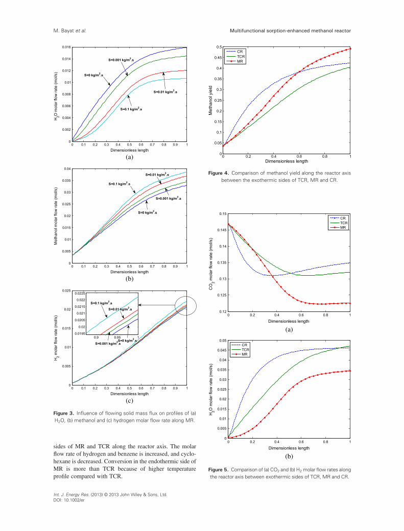
Figure 3 shows the molar flow rates of H2O and meth-anol in the inner tube and hydrogen molar flow rate inthe outer tube of MR considering the effect of flowing
solid mass flux. The simulation result of Figure 3(a) illus-trates that H2O molar flow rate is lower for higher flowingsolid mass flux, which removes more water vapor from thereactor. The increase of flowing solid mass flux results inhigher methanol molar flow rate (see Figure 3(b)) becauseof higher water removal and shifting the reaction to theproduct side. Variation of flowing solids mass flux in theinner tube influences H2 molar flow rate in the outer tube.Utilization of higher mass fluxes leads to more generatedheat in exothermic side and more transferred heat to theendothermic side. Therefore, the temperature in the endo-thermic side is higher, and as a result, more hydrogen canbe achieved in the reactor outlet (Figure 3(c)).
Figure 4 shows the comparison of methanol yield in theexothermic side of MR (this reactor is shown in Figure 1)with thermally coupled reactor (TCR) and CR. Methanolyield in MR is lower than that in CR before a certain posi-tion but increases after that and is higher than CR, whereasthe methanol yield in proposed configuration is higher thanthat in TCR for the entire reactor length. As the axiallength increases, the methanol production in MR, wherewater adsorption takes place will be significantly higherthan two other reactors. This result is attributed to thepositive effect of utilizing adsorbents in MR because wateradsorption increases the reaction rate and methanolproduction considerably.
Figure 5(a) and (b) shows the comparison of molar flowrate of CO2 and H2O in the exothermic side of MR withTCR and CR. The CO2 molar flow rate in the MR config-uration is lower than the ones in TCR and CR (Figure 5(a)). Water removal shifts the WGS reaction to the rightside, and CO2 is consumed. CO2 is one of the main airpollutants; therefore, the decrease of CO2 is beneficial forthe environment. The H2O molar flow rate profile in theMR configuration is lower than the other reactors owingto adsorption of water by flowing solids (Figure 5(b)).
Figure 6 is simultaneous plots of molar flow rate forcyclohexane, benzene and hydrogen in the endothermic
Table X. Comparison between model prediction for S=0kg m�2s� 1 and experimental data.
Reactorinlet
Reactor outlet
Exp. MR Error%
Composition (mol %)CO2 3.45 2.18 2.26 �3.67CO 4.66 1.44 1.5 �4.167H2 79.55 75.71 76.37 �0.87CH4 11.72 12.98 12.88 0.77N2 0.032 0.16 0.15 6.66H2O 0.08 1.74 1.66 4.598CH3OH 0.032 5.49 5.23 4.736Feed flow rate(mols-1) 0.565 0.51 0.5 1.96Temperature(K) 503 528 524.3 0.7
Figure 2. Influence of flowing solid mass flux on temperatureprofile in the exothermic side of MR.
Multifunctional sorption-enhanced methanol reactor M. Bayat et al.
Int. J. Energy Res. (2013) © 2013 John Wiley & Sons, Ltd.DOI: 10.1002/er
sides of MR and TCR along the reactor axis. The molarflow rate of hydrogen and benzene is increased, and cyclo-hexane is decreased. Conversion in the endothermic side ofMR is more than TCR because of higher temperatureprofile compared with TCR.
(a)
(b)
(c)
Figure 3. Influence of flowing solid mass flux on profiles of (a)H2O, (b) methanol and (c) hydrogen molar flow rate along MR.
Figure 4. Comparison of methanol yield along the reactor axisbetween the exothermic sides of TCR, MR and CR.
(a)
(b)
Figure 5. Comparison of (a) CO2 and (b) H2 molar flow rates alongthe reactor axis between exothermic sides of TCR, MR and CR.
Multifunctional sorption-enhanced methanol reactorM. Bayat et al.
Int. J. Energy Res. (2013) © 2013 John Wiley & Sons, Ltd.DOI: 10.1002/er

Figure 7(a) and (b) reveals the axial temperature profilesin the exothermic and endothermic sides of CR, TCR andMR. Heat is generated in the exothermic side, and thehighest temperature is observed in this side. The tempera-ture of the exothermic side (inner tube) is always higherthan that of the endothermic side (outer tube) to make adriving force for heat transfer. Along the exothermic side,temperature increases, reaches to a hot spot and thendecreases. In coupled reactors, the hot spots are lower thanthat of CR. Hot spot reduces the catalyst activity andproduct yields. Lower peak in the temperature profile ofcoupled reactors increases the lifetime of catalyst andmakes it more efficient in comparison with the CR. Utiliza-tion of flowing solid particles results in water adsorption,which increases the reaction rate, improves the perfor-mance of the reactor and releases more heat of reaction inthe exothermic side of MR. Therefore, higher gas phasetemperature profile in both sides of MR in comparison withTCR will be the outcome of this change (see Figure 7(a)and (b)).
One of the main tasks in GFSFBR is the measurementof pressure along the bed to decrease the costs of the
system. This information is important in designing pumpsand compressors for the fluids. Figure 8 shows the pressureprofile along the exothermic side of MR and TCR. As itwas previously mentioned, for gas-flowing solid-fixedbed contactors, the pressure drop equation consists of themodified Ergun equation and the additional term of dragcaused by the co-current flow of the particles and the gas.The lower pressure profile in MR for S = 0.1 kg m� 2 s� 1
in comparison with TCR (S = 0 kgm� 2 s� 1) can beexplained based on this additional term, which is consid-ered in pressure drop equation of MR.
Figure 9 shows the variation of reaction rate for innerand outer tubes of MR and TCR. Reaction rates in bothexothermic and endothermic sides of MR are higher thanthose in TCR. Flowing solids in the inner tube adsorbwater vapor and shift the reaction to the product side,which accelerates the reaction rate. As a result, reactionrates in the exothermic side of MR are significantly higherthan those of TCR (Figure 9(a)). Higher reaction rate in the
(a)
(b)
Figure 6. Comparison of (a) cyclohexane, benzene and (b) hy-drogen molar flow rates along the reactor axis between endo-
thermic sides of TCR and MR.
(a)
(b)
Figure 7. Comparison of temperature profiles (a) in the exother-mic side and (b) in the endothermic side of MR, TCR and CR.
Multifunctional sorption-enhanced methanol reactor M. Bayat et al.
Int. J. Energy Res. (2013) © 2013 John Wiley & Sons, Ltd.DOI: 10.1002/er

exothermic side results in more generated heat andmore transferred heat to the endothermic side; therefore,the temperature profile of MR is higher than that ofTCR in the endothermic side (see Figure 7(b)). Highertemperature profile of MR results in higher reaction rate(Figure 9(b)).
In Figure 10, the MR performance is studied fordifferent molar flow rates of the exothermic stream.Figure 10(a) and (b) illustrates the effect of molar flowrate of the exothermic stream on methanol yield andcyclohexane conversion, respectively. By increasing themolar flow rate, the amount of reactants going throughthe exothermic side increases per unit catalyst volume,and consequently, the methanol yield will reduce, whichis due to lower residence time (see Figure 10(a)). Increaseof molar flow rate in the exothermic side of MR leads toan increase in the cyclohexane conversion and then leads
(a)
(b)
Figure 9. Comparison of reaction rate (a) in the exothermic sideand (b) in the endothermic side of MR and TCR.
(a)
(b)
Figure 10. Influence of molar flow rate of the exothermicstream on (a) methanol yield and (b) cyclohexane conversion
along the reactor length for MR.
Figure 8. Pressure profile for MR and TCR.
Multifunctional sorption-enhanced methanol reactorM. Bayat et al.
Int. J. Energy Res. (2013) © 2013 John Wiley & Sons, Ltd.DOI: 10.1002/er

to a decrease. It is because of the difference between totaltransferred heat flux from the solid wall and total con-sumed heat flux in the endothermic side (see Figure 10(b)). As seen, there will be an optimum in the exothermicmolar flow rate for MR.
Figure 11 studies the influence of molar flow rate of theendothermic stream on methanol yield and cyclohexaneconversion along the reactor length. As can be seen inFigure 11(a), methanol yield changes only a little for vari-ation of flow rate in the endothermic stream. By increasingthe molar flow rate of the endothermic side, the amount ofcyclohexane going through the outer tube increases perunit catalyst volume, and consequently, the cyclohexaneproduction will reduce (Figure 11(b)).
8.2. Optimization
The optimization of the MR is conducted by the use ofdifferential evolution (DE) method in MATLAB program-ming environment, and the corresponding results are
presented in Table XI. In this table, Texo, Tend T′s, d′s andS are inlet temperature of the exothermic side, inlet temper-ature of the endothermic side, temperature of the flowingsolid phase, flowing solid diameter and mass flux offlowing solids, respectively.
Using optimal operating conditions enhances theperformance of the reactor significantly by improving thedesired production rates. The optimized MR (OMR) issimulated based on the optimization results in Table XI.Corresponding results of simulation and optimization havebeen shown and discussed in the following figures:
Figure 12 shows the comparison of methanol yield andH2O molar flow rate in the exothermic side of OMR with
(a)
(b)
Figure 11. Influence of molar flow rate of the endothermicstream on (a) methanol yield and (b) cyclohexane conversion
along the reactor length for MR.
(b)
(a)
Figure 12. (a) Methanol yield and (b) H2O molar flow rate alongthe exothermic side of MR and OMR.
Table XI. The optimized parameters for the proposedmultifunctional reactor.
Texo(K) Tend(K) T′s(K) d′s(μm) S(kg.m� 2. s�1)
535 423 499.7 1300 0.1
Multifunctional sorption-enhanced methanol reactor M. Bayat et al.
Int. J. Energy Res. (2013) © 2013 John Wiley & Sons, Ltd.DOI: 10.1002/er

MR. Using optimum conditions leads to higher conversionin OMR. Utilization of larger adsorbent particles inoptimized reactor increases water adsorption and leadsto lower water molar flow rate in output of OMR(Figure 12(b)). Because water adsorption increases thereaction rate in the exothermic side of the reactor, metha-nol yield in OMR will be higher than that of MR(Figure 12(a)).
Figure 13(a) and (b) shows axial temperature profilesin the inner and outer tubes (exothermic and endothermicsides) of OMR and MR. One of the main issues inmethanol synthesis reactors is using a higher temperaturein the first part of the reactor for higher reaction rate andthen decreasing temperature at the second part of thereactor for increasing thermodynamic equilibrium. InOMR configuration, the inlet temperature of the exother-mic side is higher than MR becuase of utilization of opti-mum inlet temperature in this side. In the OMR entrance,the generated heat in the exothermic side is lower than the
transferred heat from the solid wall to the endothermic side;thus, temperature decreases rapidly, and a cold spotdevelops. Afterward, the produced heat in the exothermicside is more than the consumed heat by the endothermic side;thus, temperature increases and makes a hot spot. At last, thetemperature decreases to 516 K in consequence of fueldepletion (Figure 13(a)). The inlet temperature of theendothermic side in OMR is lower than that of MR becauseof utilization of optimum inlet temperature. In OMR, at theentrance of outer tube (dehydrogenation side), the tempera-ture increases rapidly, and a hot spot form and then thetemperature decreases (Figure 13(b)).
Figure 14 demonstrates the comparison of cyclo-hexane, benzene and hydrogen molar flow rates in theendothermic side of OMR with MR. Using optimumoperating conditions causes the endothermic streamspends in higher temperature and shifts the reaction tobenzene production; hence, higher benzene and hydrogenmolar flow rates are achieved in OMR.
(a)
(b)
Figure 13. Variation of temperature for (a) exothermic and (b)endothermic side of OMR and MR along the reactor axis.
(a)
(b)
Figure 14. (a) cyclohexane, benzene and (b) hydrogen molarflow rates along the endothermic side of MR and OMR.
Multifunctional sorption-enhanced methanol reactorM. Bayat et al.
Int. J. Energy Res. (2013) © 2013 John Wiley & Sons, Ltd.DOI: 10.1002/er
9. CONCLUSION
A steady-state mathematical description is given toevaluate the potential of an MR with in situ wateradsorption in the exothermic side of the reactor. Zeolite4A is considered as H2O adsorbent owing to its high wateradsorption capacity. The novel configuration is designed asa double pipe reactor where highly exothermic methanolsynthesis reactions in the exothermic side are coupled withdehydrogenation of cyclohexane. In the exothermic side ofthe proposed configuration, a gas-flowing solid-fixed bedreactor (GFSFBR) is used. Simulation result indicates22.5%, 9.85% and 7.1% enhancement for methanol,benzene and hydrogen productions in MR (under H2Oremoval condition) in comparison with the zero solid massflux condition. Afterward, optimization of MR is perfor-med using the DE algorithm as a robust method tomaximize hydrogen mole fraction and methanol yield.Operating under the optimized conditions shows thehighest methanol yield and hydrogen mole fraction forMR. These features suggest that the concept of in situwater adsorption is an attractive candidate for simultaneousproduction of hydrogen and methanol.
NOMENCLATURE
Ac = Cross section area of each tube (m2)Ai = Inside area of inner tube (m2)Ao = Outside area of inner tube (m2)Ar = Archimedes number for flowing solid
particles, ¼ d3pρg ρp�ρgð Þg.μ2
� as = Specific surface area of catalyst
pellet (m2 m-3)a′s = Specific surface area of flowing
solid (m2 m-3)Cd = Drag coefficientCpg = Specific heat of the gas at constant
pressure (J mol-1 K-1)Cps = Specific heat of the catalyst at constant
pressure (J mol-1 K-1)Cp′s = Specific heat of the flowing solid at
constant pressure (J mol-1 K-1)c = Total concentration (mol m-3)Di = Tube inside diameter (m)Dij = Binary diffusion coefficient of component
i in j (m2 s-1)Dim = Diffusion coefficient of component i in
the mixture (m2 s-1)Do = Tube outside diameter (m)deq = Equivalent diameter of packing particles,
¼ 6 1� εð Þ= as þ 4D
� �� �(m)
ds = Catalyst diameter (m)d′s = Flowing solid diameter (m)Fi = Molar flow of species i (mole s-1)Ft = Total molar flow rate (mole s-1)
G = Mass flux of gas (kg m-2 s-1)ΔHads = Specific heat of adsorption (J mol-1)ΔHf,i = Enthalpy of formation of component
i (J mol-1)ΔH298 = Enthalpy of reaction at 298 °K (J mol-1)hf = Gas-catalyst heat transfer coefficient
(W m-2 K-1)h′f = Gas-solid heat transfer coefficient
(W m-2 K-1)hi = Heat transfer coefficient between fluid
phase and reactor wall in the inner tube(W m-2 K-1)
ho = Heat transfer coefficient between fluidphase and reactor wall in the outer tube(W m-2 K-1)
K = Conductivity of fluid phase S (W m K-1)kgi = Gas-catalyst mass transfer coefficient for
component i (m s-1)k′g = Gas-solid mass transfer coefficient (m s-1)L = Length of reactor (m)Mi = Molecular weight of component i
(g mol-1)N = Number of components used in the model
(Nexo = 7,Nend = 4)P = Total pressure (bar)q = Concentration of water adsorbed in
flowing solids (mol kg-1)qe = Equilibrium concentration of adsorbed
water (mol kg-1)R = Universal gas constant (J mol-1 K-1)Res = Reynolds number of packing elementsRe′s = Reynolds number of flowing solidsri = Reaction rate of component i (mol kg-1 s-1)S = Mass flux of flowing solids (kg m-2 s-1)Tg = Bulk gas phase temperature (K)Ts = Temperature of catalyst pellet (K)T′s = Temperature of flowing solids (K)U = Overall heat transfer coefficient between
two sides (W m-2 K-1)Ug = Real gas velocity, ¼ G
ρgε′
. ��(m s-1)
ug = Superficial gas velocity (m s-1)ur = Relative velocity for co-current flow of
gas and flowing solids, (=Ug� u′s) (m s-1)u′s = Real flowing solids velocity, ¼ S
ρ′sβ ��
(m s-1)yi = Mole fraction of component i in the fluid
phase(mol mol-1)ysi = Mole fraction of component i on catalyst
phase (mol mol-1)z = Axial reactor coordinate (m)
Greek letter
β = Flowing solids holdup (=βd + βs)βd = Dynamic flowing solids holdup (-)βs = Static flowing solids holdup
Multifunctional sorption-enhanced methanol reactor M. Bayat et al.
Int. J. Energy Res. (2013) © 2013 John Wiley & Sons, Ltd.DOI: 10.1002/er
ε = Void fraction of catalytic bed (m3 m-3)ε′ = Void fraction corrected due to presence of
the flowing solids, (=ε� β) (m3 m-3)φ = Sphericity of packed bed elementη = Effectiveness factorμ = Dynamic viscosity (pa s)ρB = Catalytic bed density (Kg m-3)ρg = Gas density (Kg m-3)ρS = Catalyst density (Kg m-3)ρ′S = Flowing solid density (Kg m-3)
Subscripts
0 = Entrance of reactori = Numerator for componentj = Numerator for tube (1: inner tube, 2:
outer tube)
Abbreviations
CR = Conventional reactorTCR = Thermally coupled reactorMR = Multifunctional reactorGFSFBR = Gas-flowing solids-fixed bed reactor
REFERENCES
1. Demir N. Hydrogen production via steam-methanereforming in a SOMBRERO fusion breeder withceramic fuel particles. International journal of hydro-gen energy 2012; 38:853–860.
2. Bayat M, Rahimpour MR. Production of hydrogen andmethanol enhancement via a novel optimized ther-mally coupled two-membrane reactor. Internationaljournal of energy research 2012; 37:105–120.
3. Rahimpour MR, Bayat M. A novel cascade membranereactor concept for methanol synthesis in the presenceof long-term catalyst deactivation. Internationaljournal of energy research 2010; 34:1356–1371.
4. Khademi MH, Jahanmiri A, Rahimpour MR. A novelconfiguration for Hydrogen production from couplingof methanol and benzene synthesis in a hydrogen permselective membrane reactor. International Journal ofHydrogen Energy 2009; 34:5091–5107.
5. Khademi MH, Rahimpour MR, Jahanmiri A. Differen-tial evolution (DE) strategy for optimization of hydro-gen production, cyclohexane dehydrogenation andmethanol synthesis in a hydrogen-permselective mem-brane thermally coupled reactor. International Journalof Hydrogen Energy 2010; 35:1936–1950.
6. Rezaie N, Jahanmiri A, Moghtaderi B, RahimpourMR. A comparison of homogeneous and heteroge-neous dynamic models for industrial methanol reactorsin the presence of catalyst deactivation. ChemicalEngineering and Processing 2005; 44:911–921.
7. Rahimpour MR, Pourazadi E. A comparison ofhydrogen and methanol production in a thermallycoupled membrane reactor for co current and countercurrent flows. International Journal of EnergyResearch 2011; 35:863–882.
8. Bayat M, Dehghani Z, Hamidi M, Rahimpour MR.Methanol synthesis via sorption-enhanced reactionprocess–Modeling and multi-objective optimization.Journal of the Taiwan Institute Chemical Engineering.http://dx.doi.org/10.1016/j.jtice.2013.06.013.
9. Roes AWM, van Swaaij WMP. Hydrodynamicbehavior of a gas-solid counter-current packed columnat trickle flow. Chemical Engineering Journal 1979;17:81–89.
10. Nikacevic N, Dudukovic A. Fluid dynamic of gas-flowing solids-fixed bed contactors. Chemical Industryand Chemical Engineering Quarterly 2007; 13:151–162.
11. Zhu W, Gora L, van den Berg AWC, Kapteijn F,Jansen JC, Moulijn JA. Water separation frompermanent gases by a zeolite 4A membrane. Journalof Membrane Science 2005; 253:57–66.
12. Timofeev DP, Kabanova ON. Kinetics of thedesorption of water vapors from molded zeolites,types A and X. Bulletin of the Academy of Sciencesof the USSR, Division of Chemical Science 1966;4:610–614.
13. Directie Staatsmijnen. French Patent 978287; 1948.14. Kuczynski N, Oyevaar MH, Pieters RT, Wisterterp
KR. Methanol synthesis in a countercurrent gas-solid-solid trickle flow reactor. An experimental study.Chemical Engineering Science 1987; 42:1887–1898.
15. Westerterp KR, Bodewes TN, Vrijiland MS,Kuczynski MA. Two New Methanol Converters.Hydrocarbon Processing 1988; 67:69–73.
16. Nikacevic N, Jovanovic M, Petkovska M. Enhancedammonia synthesis in multifunctional reactor with in-situ adsorption. Chemical Engineering Research andDesign 2011; 89:398–404.
17. Iliuta I, Iliuta MC, Larachi F. Sorption-enhanceddimethyl ether synthesis—Multiscale reactor modeling.Chemical Engineering Science 2011; 66:2241–2251.
18. Graaf GH, Scholtens H, Stamhuis EJ, BeenackersAACM. Intra-particle diffusion limitations in low-pressure methanol synthesis. Chemical EngineeringScience 1990; 45:773–783.
19. Graaf GH, Sijtsema PJJM, Stamhuis EJ, Joosten GEH.Chemical equilibrium in methanol synthesis. ChemicalEngineering Science 1986; 41:2883–2890.
Multifunctional sorption-enhanced methanol reactorM. Bayat et al.
Int. J. Energy Res. (2013) © 2013 John Wiley & Sons, Ltd.DOI: 10.1002/er

20. Itoh N. A membrane reactor using palladium. AICHEJournal 1987; 33:1576–8.
21. Jeong BH, Sotowa KI, Kusakabe K. Catalyticdehydrogenation of cyclohexane in an FAU-typezeolite membrane reactor. Journal of MembraneScience 2003; 224:151–158.
22. Bayat M, Rahimpour MR. Simultaneous utilization oftwo different membranes for intensification ofultrapure hydrogen production from recuperative cou-pling autothermal multitubular reactor. InternationalJournal of Hydrogen Energy 2011; 36:7310–7325.
23. Jeong BH, Sotowa KI, Kusakabe K. Modeling of anFAU type zeolite membrane reactor for the catalyticdehydrogenation of cyclohexane. Chemical Engineer-ing Journal 2004; 103:69–75.
24. Ranz WE, Marshall WR. Evaporation from drops II.Chemical Engineering Progress 1952; 48:173–180.
25. Do DD. Adsorption analysis: Equilibria and kinetics.Imperial College Press, London; 1998, vol. 2, p. 72.
26. Perry RH, Green DW, Maloney JO. Perry’s chemi-cal engineers’handbook (7th edn). McGraw-Hill:NewYork, 1977.
27. Cussler EL. Diffusion, mass transfer in fluid systems.Cambridge University Press: Cambridge, 1984.
28. Wilke CR. Estimation of liquid diffusion coefficients.Chemical Engineering Progress 1949; 45:218–224.
29. Reid RC, Sherwood TK, Prausnitz J. The properties ofgases and liquids (3rd edn). McGraw-Hill: New York,1977.
30. Smith JM. Chemical engineering kinetics. McGraw-Hill: New York, 1980.
31. Tather M, Erdem-senatalar A. Optimization of thecycle durations of adsorption heat pumps employingzeolite coatings synthesized on metal supports.Microporous Mesoporous Mater 2000; 34:23–30.
32. Dudukovic AP, Nikacevic NM, Petrovicand DL,Predojevic ZJ. Solids holdup and pressure drop ingas-flowing solids-fixed bed contactors. Industrialand Engineering Chemistry Research 2003;42:2530–2535.
33. Pandu Rangaiah G. Multi-objective optimization: tech-niques and applications in chemical engineering, vol.1. World Scientific Publishing Company, Singapore;2008.
34. Farsi M, Khademi MH, Jahanmiri A, Rahimpour MR.Optimal conditions for hydrogen production fromcoupling of dimethyl ether and benzene synthesis.International Journal of Hydrogen Energy 2010;36:299–310.
35. Price K, Storn R. Differential Evolution- a simpleevolution strategy for fast optimization. Dr. Dobb’sJournal 1997; 22:18–24.
Multifunctional sorption-enhanced methanol reactor M. Bayat et al.
Int. J. Energy Res. (2013) © 2013 John Wiley & Sons, Ltd.DOI: 10.1002/er