hydraulics of 3d plunge pool scour
TRANSCRIPT

Dow
nloa
ded
from
asc
elib
rary
.org
by
MIS
SOU
RI,
UN
IV O
F/C
OL
UM
BIA
on
04/1
8/13
. Cop
yrig
ht A
SCE
. For
per
sona
l use
onl
y; a
ll ri
ghts
res
erve
d.
Hydraulics of 3D Plunge Pool ScourStefano Pagliara1; Massimiliano Amidei2; and Willi H. Hager, F.ASCE3
Abstract: The main flow features of three-dimensional plunge pool scour are explored in this experimental research for steady flowconditions. These include the maximum depth of the scour hole, its streamwise geometry, and the maximum width, the maximum heightof the ridge, its shape in plan view, and its profile. Expressions for all these parameters are presented in terms of the basic scour variables,including the approach flow densimetric Froude number, the jet impact angle, the jet diameter, and the tailwater elevation above theoriginally horizontal sediment bed. This research is based on a previous work relating to two-dimensional plunge pool scour. Differencesbetween the two phenomena are outlined, and the results are discussed in terms of engineering applications. The results of the two worksallow for the prediction of the most salient features of plunge pool scour for both the dynamic and the static scour holes.
DOI: 10.1061/�ASCE�0733-9429�2008�134:9�1275�
CE Database subject headings: Hydraulics; Hydraulic structures; Scour; Sediment; Spillways; Water flow.
Introduction
Plunge pools are a common feature of dam engineering. They arelocated at the terminal zone of energy dissipation for trajectoryspillways. Predicting the main features of a plunge pool is impor-tant in terms of structural stability, tailwater submergence, andridge geometry, i.e., the aggradation excavated by the high-speedjet. The latter is typically an air–water mixture flow, as waspreviously accounted for by Pagliara et al. �2006�. Together withthe experimental study by Canepa and Hager �2003�, the featuresof the two-dimensional �2D� scour hole were analyzed, basedon an experimental campaign conducted at Versuchsanstalt fürWasserbau, Hydrologie und Glaziologie VAW, of the Swiss Fed-eral Institute of Technology ETH, Zurich.
The present work extends previous results on 2D to three-dimensional �3D� plunge pool scour. Given the large number ofbasic parameters, some of the previously investigated effects werenot further considered herein. These include the sediment charac-teristics and the effect of air, the addition of an upstream baseflow into the plunge pool zone, and the submerged jet flow con-figuration. Therefore, all present data refer to one sediment andunsubmerged blackwater jets. The equations describing the 3Dplunge pool scour are based on the previously established findingsof Pagliara et al. �2006� for 2D plunge pool scour.
The main parameter of a 3D plunge pool scour is the scourwidth ratio �=bm /b with bm as the maximum scour hole widthdetermined in the following as a function of the basic parametersand b as the channel width. Accordingly, only the parameter �determines whether a scour hole may be considered 2D or 3D.The latter has the particular plan shape shown in Fig. 1, includingan elliptical base and a half-moon-shaped ridge surrounding the
1Professor, Univ. di Pisa, Via Gabba 22, I-56100 Pisa, Italy.2Research Assistant, Univ. di Pisa, Via Gabba 22, I-56100 Pisa, Italy.3Professor, VAW, ETH-Zurich, CH-8092 Zurich, Switzerland.Note. Discussion open until February 1, 2009. Separate discussions
must be submitted for individual papers. The manuscript for this paperwas submitted for review and possible publication on March 23, 2006;approved on January 31, 2008. This paper is part of the Journal ofHydraulic Engineering, Vol. 134, No. 9, September 1, 2008. ©ASCE,
ISSN 0733-9429/2008/9-1275–1284/$25.00.JOURNAL
J. Hydraul. Eng. 2008.1
scour hole. In contrast, the 2D scour hole has both a cylindricalscour hole and ridge geometry. The presence of the ridge, both forthe 2D and the 3D plunge pool arrangements, is important, be-cause of the flow recirculation developed in the scour hole. Aridge removal results in a deeper scour hole associated with asmaller tailwater, as demonstrated by Pagliara et al. �2006� andreconsidered in the present work.
3D plunge pool scour has received little attention in the past.As for other topics in hydraulic engineering, studies were mainlydirected to particular site conditions that do not allow for a gen-eralized approach. A notable exception are the works of ProfessorRajaratnam, Univ. of Alberta, Canada. Rajaratnam and Berry�1977� for instance used air jet nozzle diameters of 0.925 and0.25 in. �23.5 and 6.3 mm� to investigate the scour hole featuresof sand and polystyrene beds. Rajaratnam �1980� investigated thescour hole characteristics under the presence of a cross flow, asetup not further investigated hereafter. Other studies in this gen-eral topic were presented by Mih �1982� and Mih and Kabir�1983�, thereby exploring the possibility of fine sediment removalfrom a granular bed with a high-speed nozzle. The work ofAnderson and Blaisdell �1982� is not considered relevant hereinbecause of the relatively small jet impact velocity leading to acurved jet trajectory, in contrast to the almost straight jet trajec-tory considered here. A similar work was also presented byBormann and Julien �1991� in which the jet trajectory deviatesappreciably from a straight line, because of the relatively small jetFroude numbers. In the present research, the minimum densimet-ric particle Froude number was of the order of 4, providing analmost linear jet trajectory, as is typical for trajectory spillwaysclose to the jet impact zone. The studies involving a vertical cir-cular jet were also not considered because of the almost perfectradial symmetry of the scour hole. In the following, the mainresults of a hydraulic model study are highlighted along with adiscussion and the limitations of the results that have to be ac-counted for in practice.
Experiments
The experiments were conducted at the Hydraulic Laboratory of
the University of Pisa, Italy. The channel had a total length ofOF HYDRAULIC ENGINEERING © ASCE / SEPTEMBER 2008 / 1275
34:1275-1284.

Dow
nloa
ded
from
asc
elib
rary
.org
by
MIS
SOU
RI,
UN
IV O
F/C
OL
UM
BIA
on
04/1
8/13
. Cop
yrig
ht A
SCE
. For
per
sona
l use
onl
y; a
ll ri
ghts
res
erve
d.
25 m of which the test reach was 6 m. The rectangular channelwas 0.80 m wide; the widths of the test reach were 0.80 m, andreduced to 0.40 and 0.20 m. After the sediment bed had beengraded an initial water depth ho above the sediment bed wasestablished in the channel. The plunge pool scour tests were madeas previously by Pagliara et al. �2006�. Instead of the completesetup including a chute and a trajectory spillway discharging theair–water mixture into the air, the present experiments consideredthe impact features of an unsubmerged high-speed water jet en-training air into a pool of water over an initially plane sedimentsurface using a circular pipe of internal diameter D=16, 27, 35,and 51 mm. The water �subscript W� discharge in the pipe wasvaried between QW=0.35 and 10.0 l /s. The relative tailwater el-evation T=ho /D varied between 0.80 and 10, i.e., as previouslyinvestigated by Pagliara et al. �2006�. The jet impact angles rela-tive to the horizontal were �=30, 45, and 60°. Vertical jets werenot considered, because of a different flow pattern.
This study involved one nearly uniform sediment with d10
=8.62 mm, d16=9.00 mm, d60=10.60 mm, d84=11.40 mm, andd90=11.63 mm resulting in a sediment nonuniformity parameter�= �d84 /d16�1/2=1.13. Its angle of repose in fully saturated condi-tions was 29.5°, whereas 37.1° applied under dry conditions. Thisresearch includes a total of 291 tests of which 198 were made inthe 0.80 m wide channel, 29 in the 0.40 m wide channel, and 64aimed to compare the previous findings relative to the 2D flowconditions with the 0.20 m wide channel. In terms of the jet im-pact angle, 127 tests were made for �=30°, 99 for �=45°, and65 tests for �=60°. For each test, the axial bed profile was mea-sured by a special point gauge fitted with a 20 mm circular plateat its lower end, with the methodology described by Pagliara et al.�2006�, at times t=1, 5, and 20 min and at the test end typically40 min from test initiation at t=0 when equilibrium scour condi-tions had normally developed. The transverse scour hole geom-etry was then also recorded prior to stopping the water, referred toas the dynamic scour. The so-called static scour hole featureswere observed after the water had been drained from the channel.
Classification of 3D Scour Holes
The features of a 3D plunge pool scour hole are more complexthan those of the 2D configuration. The jet impinging onto thesediment bed results essentially in a radial flow from the impactpoint with major momentum components directed laterally to theapproach flow direction. Secondary currents are set up that havebeen barely described in previous studies. The flow phenomena in
Fig. 1. View of 3D plunge pool for free jet flow ��=30° �
the main flow direction may be described as follows. Upstream
1276 / JOURNAL OF HYDRAULIC ENGINEERING © ASCE / SEPTEMBER 2
J. Hydraul. Eng. 2008.1
from the jet impact zone, sediment is not scoured but slides byavalanches into the scour hole, from where it is entrained by thejet and transported up onto the downstream scour hole zone. Twozones may be distinguished: �1� active cup-shaped scour holezone close to the jet impact with direct sediment entrainmentending in a small rim; and �2� passive scour hole zone from therim up to the sediment ridge, where suspended material is mainlydeposited. The angles of the scour hole and of the material de-posited beyond the ridge approach the angle of natural reposebelow water. The ridge downstream from the scour hole has asignificant effect on the flow pattern in the scour hole. Accordingto Pagliara et al. �2006� a removal of the ridge increases the scourhole depth because the surface recirculation is increased by theridge presence. By lowering the tailwater level the transverse ve-locity components close to the jet impact zone increase resultingin a more 3D flow pattern. For a tailwater depth smaller than 3 jetdiameters, the ridge may be higher than the water surface and theflow is laterally deflected by the ridge. A similar phenomenonoccurs as the jet impact angle increases beyond a certain limitassociated with a part of the flow being deflected into the up-stream direction.
For a high �denoted H� tailwater submergence and a small�denoted L for low� jet impact angle, the scour hole has a largestreamwise extension, referred to as Type HTwL� �Fig. 2�. As thejet impact angle increases �denoted I for intermediate� under asimilar tailwater elevation, a vortex develops upstream from thejet impact zone resulting in a less elongated scour hole geometry,referred to as Type HTwI�. Then a dune develops along the tail-water flanks of the scour hole. Further increasing the jet impactangle, the Flow Type HTwH� develops with an increase of theridge formation tending to an almost circular plan of the plungepool. As the tailwater elevation is reduced, the effect of the jetimpact angle appears to reduce and a large portion of the waterflow is deflected by the sediment ridge. Table 1 and Fig. 2 sum-marize these observations.
Scour Depth Features
Flow Features
Fig. 3 shows a sketch of the 3D �subscript T� scour hole. It in-cludes in the side view the original water depth ho, the maximumscour �subscript m� depth zmT, and the maximum ridge �subscriptM� elevation zMT. The main streamwise scour hole lengths are liT
between the geometrical jet impact point on the original sediment
Fig. 2. Types of 3D plunge pool scour as function of impact angle �°and relative tailwater T
bed and the scour hole origin, lmT as the distance from the scour
008
34:1275-1284.

Dow
nloa
ded
from
asc
elib
rary
.org
by
MIS
SOU
RI,
UN
IV O
F/C
OL
UM
BIA
on
04/1
8/13
. Cop
yrig
ht A
SCE
. For
per
sona
l use
onl
y; a
ll ri
ghts
res
erve
d.
hole origin to the point of maximum scour depth, and laT as thescour hole length. Further lengths are those relative to the ridgemaximum lMT and to the end of the sediment deposition luT. Theplan view parameters are the maximum scour hole width bm, theangle � subtended by the arc along the top of the ridge with a halfarc length of stot measured from the maximum ridge elevation tothe ridge beginning, and s as the coordinate measured from themaximum ridge elevation toward the ridge beginning �Fig. 3�.
Pagliara et al. �2006� observed that the maximum scourhole depth zm of the 2D flow configuration is linearly related tothe densimetric particle Froude number Fd90=V / �g�d90�1/2, withg�= ���s−�� /��g as the reduced gravitational acceleration involv-ing the densities �s and � of sediment and water. Fig. 4 supportsthis finding for 3D jet flow showing the 3D data for relative scourhole depth Zm=zm /D in terms of Fd90 together with the previousfinding relative to 2D scour. For a relative submergence of T�10, the scour depth of the 3D configuration is significantlylarger as compared to the 2D case. This results from a momentumconcentration in the almost spherically shaped lower scour holeportion for the 3D case. In contrast, Fig. 4�b� shows 3D the datafor �=45° and T�5, which almost collapse to the 2D formula-tion of Pagliara et al. �2006�. For �=60° and T�1, the 3D scourhole depth is smaller than in the 2D case. Accordingly, dependingon the two parameters � and T and possibly on additional param-eters, the 3D scour hole depth may be larger, equal to, or smallerthan the 2D configuration.
Fig. 5�a� shows the maximum 3D scour depths ZmT�Fd90� for�=30° and a variable relative tailwater submergence T. The plotconfirms that as larger T, the deeper is ZmT. In contrast, Zm isinversely related to T in the scour depth equation proposed byPagliara et al. �2006� for 2D scour. Note that the relation betweenZmT and Fd90 is practically linear. Fig. 5�b� shows the relationZmT�Fd90� for the three jet impact angles �=30, 45, and 60°: Thesmaller the jet angle �, the deeper the scour hole. This effect hasto do with the modified ridge geometry. Whereas the ridge in the2D case resulted in deeper scour holes for large angles �, thepartial ridge geometry in the 3D scour hole retains less suspendedsediment. Fig. 6 also indicates a larger scour surface for a small
Table 1. Classification of 3D Jet Phenomena Related to Scour �CompareAlso with Fig. 2�
Type Description
HTwL� Maximum scour depth is large; scour hole is elongatedwith the ridge mainly along its tailwater portion; ridgeheight is large because the jet flow follows practically thedirection of the jet axis.
HTwI� Scour activity is less developed in the jet impact directionthan for HTwL� resulting in a smaller scour depth. Also,the ridge is less high and develops mainly on the scourhole sides. The flow direction is essentially axial with atendency to transverse flow.
HTwH� Scour hole tends to be circular shape along with areduction of the scour depth. The flow direction over thescour hole is no more axial and the water flows moreradially from the jet impact zone.
LTwL� With a tailwater reduction, the scour hole is lessdeveloped and has an almost circular plan shape. The flowdirection from the impact zone is radially outwards.
LTwH� All flow characteristics previously described are amplified,in addition to a flow portion deflected in the directionagainst the jet flow. For vertical jets, almost circular scourholes result.
jet angle as compared to large values of �.
JOURNAL
J. Hydraul. Eng. 2008.1
Equation for Scour DepthPagliara et al. �2006� proposed the following relationship for themaximum 2D scour hole depth:
Zm = − f1�Fd90�f2�� ° �f3���f4�T�f5���f6�Fu� �1�
The individual functions f account for the effects of
Densimentric Froude number, f1�Fd90� = Fd90 �2�
Impact jet angle, f2��� = �− 0.38 sin�� + 22.5 ° �� �3�
Jet air content, f3��� = �1 + ��−0.75 �4�
Tailwater, f4�T� = �1/0.30��0.12 ln�1/T� + 0.45� �5�
Fig. 3. Sketch of scour hole in �a� longitudinal; �b� plan view; and �c�extrapolation of bm
Granulometry, f5��� = − �0.57� + 0.33� �6�
OF HYDRAULIC ENGINEERING © ASCE / SEPTEMBER 2008 / 1277
34:1275-1284.

Dow
nloa
ded
from
asc
elib
rary
.org
by
MIS
SOU
RI,
UN
IV O
F/C
OL
UM
BIA
on
04/1
8/13
. Cop
yrig
ht A
SCE
. For
per
sona
l use
onl
y; a
ll ri
ghts
res
erve
d.
Approach flow, f6�Fu� = �1 + Fu0.50� �7�
To expand the validity of Eq. �1� for 3D scour holes, a number ofadditional effects have to be accounted for. 3D plunge pool scourinvolves the width parameter �=bm /b in which bm is the maxi-mum scour width and b the channel width �see the following�. For��1.50 the scour plan shape is 3D, whereas it is nearly 2D for��3.0. For ��1 the value of bm was determined by extrapolat-ing the elliptical plan shape of the scour hole to outside the glasssides of the test channel of restricted width b �Fig. 3�c��. Fig. 7shows the relation ZmT /Zm�T� for 2.5���3.0 for the three jetimpact angles, demonstrating that ZmT /Zm�1. The three correc-tion terms for 3D scour holes with �1.5 were fitted with theavailable data and � �expressed in degrees, referred to as �°� as
f7��� = 0.140 �8�
Fig. 4. Zm versus Fd90 for �a� T=10, �=30°; �b� T=5, �=45°; and�c� T�1, �=60°; �line� 2D scour �Pagliara et al. 2006�
f8��� = �1.360 − 0.012� ° � �9�
1278 / JOURNAL OF HYDRAULIC ENGINEERING © ASCE / SEPTEMBER 2
J. Hydraul. Eng. 2008.1
f9�T� = �4 + T� �10�
The expanded equation �1� for the maximum depth of a 3D scourhole
ZmT = − f1�Fd90�f2���f3���f4�T�f5���f6�Fu�f7���f8���f9�T�
�11�
applies for both 2D and 3D scour holes with f7���f8���f9�T�=1for ��3.0; and with Eqs. �8�–�10� for �1.50 along with alinear interpolation between the two for 1.50���3.0. Eq. �11�is subject to the limitations: �1� 0.8T10; �2� 30° �60°;�3� 4Fd9030; and �4� �0.20, in addition to the limitationsfor the 2D scour equation. Fig. 8 compares the predictions withthe observations and demonstrates a reasonable agreement of thedata within the margins of essentially �20%. In the intermediaterange 1.50���3.00, a linear interpolation was applied �see thefollowing�.
Maximum Static Scour DepthAccording to Pagliara et al. �2004�, a distinctive difference existsbetween the “static” and the “dynamic” scour holes. The staticscour hole applies to conditions when the jet flow is stopped aftera test, whereas the dynamic scour hole corresponds to conditionswith the jet flow turned on. The latter may not be observed inprototypes whereas static scour holes may be surveyed after aflood. It was found that the difference between the two types ofscour holes increases essentially with the jet impact angle �. For�=30° only small differences were observed, whereas the differ-ence is particularly significant for �=60°. Angles larger than thenatural angle of repose are impossible in static scour holes andsediment suspended in the scour hole during jet flow tends to a
Fig. 5. �a� Tailwater effect for 3D scour for �1.50, expressedas ZmT versus Fd90 for �=30°; �b� jet angle effect on ZmT forT=7.5
reduction of the static scour hole depth �Pagliara et al. 2006�.
008
34:1275-1284.

JOURNAL
J. Hydraul. Eng. 2008.1
Dow
nloa
ded
from
asc
elib
rary
.org
by
MIS
SOU
RI,
UN
IV O
F/C
OL
UM
BIA
on
04/1
8/13
. Cop
yrig
ht A
SCE
. For
per
sona
l use
onl
y; a
ll ri
ghts
res
erve
d.
Let zmT and zsT be the maximum dynamic and static �subscripts� scour hole depths of a 3D scour hole. In addition to thejet impact angle, the tailwater elevation has an effect on theratio between the two due to the changes in the jet impact pro-cess. Fig. 9 compares the two normalized depths ZmT=zmT /D andZsT=zsT /D for various values of T and �=30°. As T increases, thedifferences between ZmT and ZsT reduce, whereas the ratiobetween the two is almost 50% for T=1. The reason for the tail-water effect appears to be associated with the suspended sedi-ment: for a high tailwater depth the jet flow continues straight intothe tailwater whereas the ridge deflects the impacting jet for a lowtailwater elevation. This effect is amplified for larger angles �, aswas previously discussed.
Pagliara et al. �2004� proposed for the maximum depth of a 2Dstatic scour hole
Zs = 0.75Zm14�−0.75
�12�
Fig. 10 compares the static and the dynamic 3D scour holes fortwo tailwater levels and �=30°. The suspended sediment in the
Fig. 8. Maximum scour depth of 3D scour hole ZmT computed andmeasured, with �20% lines
Fig. 9. Comparison between ZmT and ZsT for �=30° and differentvalues of T �lines� Eq. �14�
Fig. 6. Axial scour hole profiles for T=10 and �= �a� 30°; �b� 45°;and �c� 60° for otherwise identical flow conditions
Fig. 7. Function ZmT /Zm�T� for 2.5���3 and 30° �60°demonstrating a quasi-2D scour depth
OF HYDRAULIC ENGINEERING © ASCE / SEPTEMBER 2008 / 1279
34:1275-1284.

Dow
nloa
ded
from
asc
elib
rary
.org
by
MIS
SOU
RI,
UN
IV O
F/C
OL
UM
BIA
on
04/1
8/13
. Cop
yrig
ht A
SCE
. For
per
sona
l use
onl
y; a
ll ri
ghts
res
erve
d.
dynamic scour hole may be well identified. It is also observed thatthe ridge of a 3D scour hole is not eroded as in the 2D casebecause water flows around the surface topography. Fig. 11 showsthe ratio Zs,meas /Zs,comp in terms of the relative tailwater elevationT for static scour hole conditions. An increase of T increasesalmost linearly the depth ratio, independent of the jet impactangle �, such that for 0.8�T�10 and within the �20% margins
Zs,meas/Zs,comp = 0.06T + 0.7 �13�
This feature was expanded to the 3D scour hole, thereby account-ing for the effect of the relative scour hole width �=bm /b. Theresulting expression from Eqs. �12� and �13� is
Zs = �0.06T + 0.7��0.75Zm14�−0.75
��ZsT �14�
where �ZsT=1 for ��3.0, and
�ZsT = �0.879 + 0.274� − 0.008� ° � · �1.165 − 0.026T�,
for � 1.50 �15�
Eqs. �14� and �15� apply for 0.8T10; 30° �60°;4Fd9030; and �0.20. Fig. 12 compares the data with theprediction for both the 2D and 3D tests. For 1.50���3.00
Fig. 10. Comparison between dynamic �left� and static �right� 3D ssuspended sediment in the dynamic scour holes.
Fig. 11. Relationship between Zs,meas /Zs,comp and T with �dashedline� Eq. �13�
1280 / JOURNAL OF HYDRAULIC ENGINEERING © ASCE / SEPTEMBER 2
J. Hydraul. Eng. 2008.1
a linear interpolation between the values at �=1.50 and �=3.00was applied.
Scour Hole Length Features
The essential parameters of the 2D scour hole geometrywere identified as lm, la, lM, and lu. All dimensionless lengthsLm= lm /D, La= la /D, LM = lM /D, and LU= lu /D increase with Fd90
and vary with the jet impact angle � and the relative tailwaterelevation T. Pagliara et al. �2006� proposed for unsubmerged jetsthat form 2D scour holes
Lm = 1.5 + �1 − 0.01� ° �Fd90 �16�
La = 2.5�1 + 1.05 exp�− 0.030� ° �Fd90� �17�
Fig. 13 relates to 3D test data with �=30° and shows theparameter LaT as a function of Fd90. Note the increase of LaT
with increasing T. The effect of 3D flow was accounted forwith a parameter �LaT defined as �LaT=1 for �3.0, whereasfor �1.50
oles for �=30° and T= �a� 5 and �b� 3. Note the large amount of
Fig. 12. Comparison of Zs,comp with Zs,meas for both 2D and 3D tests
cour h
008
34:1275-1284.

Dow
nloa
ded
from
asc
elib
rary
.org
by
MIS
SOU
RI,
UN
IV O
F/C
OL
UM
BIA
on
04/1
8/13
. Cop
yrig
ht A
SCE
. For
per
sona
l use
onl
y; a
ll ri
ghts
res
erve
d.
�LaT = �0.168 + 0.062T + 0.020� ° ��1.217 − 0.013Fd90��0.851
+ 0.345�� �18�
Accordingly, the modified equation �17� reads �R2=0.87�
LaT = 2.5�1 + 1.05 exp�− 0.030� ° �Fd90��LaT �19�
Likewise, the relative length Lm from �16� can be extended to the3D case as �R2=0.90�
LmT = �1.5 + �1 − 0.01� ° �Fd90��LmT �20�
where �LmT=1 for ��3; whereas for ��1.50�R2=0.88�
�LmT = �1.705 − 0.012� ° − 0.010Fd90��0.719 + 0.061T� �21�
In the transition range 1.50���3.00 a linear interpolation be-tween the limit values �=1.50 and �=3.00 was made. The limi-tations of Eqs. �18� and �21� are as for the previous correlations.
Scour Hole Plan Features
The 3D scour hole characteristics were demonstrated to de-pend solely on the relative scour hole width �=bm /b. The maxi-mum scour hole width bm increases with Fd90, �, and T. Fig. 14shows Bm�Fd90� for various tailwater elevations T and �=45°,with Bm=bm /D. Note that large values of T produce a large rela-tive width Bm. It was observed that a scour hole tends to the
Fig. 13. Function LaT�Fd90� for �=30° and different values of T
Fig. 14. Relation Bm�Fd90� for various values of T and �=45°
JOURNAL
J. Hydraul. Eng. 2008.1
circular shape for large jet angles, whereas it is more ellipticalotherwise. Accordingly, the maximum relative scour hole widthBm=bm /D was related to the length LaT. Fig. 15 shows the func-tion Bm�LaT� for various jet impact angles �, from which thistrend is supported. The proposed relation among the governingparameters is with R2=0.75 and the previously stated ranges ofvalidity
Bm = �0.500 + 0.008� ° �LaT �22�
Eq. �22� states that Bm increases essentially with LaT and that theadditional effect of � is small.
The ridge plan profile is half-moon shaped. The ridge startmay be described with the subtended angle � �Fig. 3� with vertexat the point of maximum scour depth. For impact angles rangingbetween 30 and 60°, �=160° ��40° �, as shown in Fig. 16, is
Fig. 15. Relation between measurements of LaT and Bm=bm /Dmeas
for different jet impact angles �
Fig. 16. Angle � as a function of �a� T; �b� Fd90
OF HYDRAULIC ENGINEERING © ASCE / SEPTEMBER 2008 / 1281
34:1275-1284.

Dow
nloa
ded
from
asc
elib
rary
.org
by
MIS
SOU
RI,
UN
IV O
F/C
OL
UM
BIA
on
04/1
8/13
. Cop
yrig
ht A
SCE
. For
per
sona
l use
onl
y; a
ll ri
ghts
res
erve
d.
practically independent of both T and Fd90.The nondimensional axial profile of the scour hole may be
described with the normalized coordinates Xm= �x− lmT� / laT
and Zm=z /zmT �Pagliara et al. 2006�, thereby accounting forthe scalings in Eqs. �11� and �19�, with x as the streamwise co-ordinate measured from the scour hole origin. The degree ofthe longitudinal scour hole symmetry �subscript S� is describedwith the symmetry parameter XS=−2lmT / laT. For XS=−1, thepoint of maximum scour depth is at 0.50laT. Fig. 17 indicates thatXS of 3D scour holes increases from about XS��=30° �=−1.4 toXS��=45° �=−1.25 parallel to 2D scour holes. For larger jet im-pact angles, the two curves diverge due to the differences betweenthe two scour patterns. The points plotted in Fig. 17 represent theaverage XS values for different jet impact angles for both the 2Dand 3D cases.
Length of Impact Point from Scour Origin
The dimensionless length LiT= liT /D localizes the scour hole ori-gin in terms of the fictitious jet impact point on the scour surface�Fig. 3�. Fig. 18 shows the relationship LiT�Fd90� for a range oftailwater elevations T and �=30°. The trend of data may be givenwith R2=0.79 as
LiT = ��0.035 + 0.034T − 0.001� ° �Fd90 + �7.667 − 0.100� ° ��
�1.285 − 0.361�� �23�
The parameter LiT essentially increases with T and decreases withthe jet impact angle �. The validity of Eq. �23� is as previouslyestablished for the other parameters. It was noted from a detaileddata analysis that a poorer correlation resulted for �=60° andsmall values of T.
Fig. 17. Scour hole symmetry parameter XS as a function of jetimpact angle � for 2D and 3D jet
Fig. 18. Relation between LiT and Fd90 as function of T for �=30°
1282 / JOURNAL OF HYDRAULIC ENGINEERING © ASCE / SEPTEMBER 2
J. Hydraul. Eng. 2008.1
Scour Hole Volume
The volume of the scour hole wm under dynamic jet flow condi-tions may be of interest in applications. Its dimensionless valuewas expressed as Wm= �g�d90�1/2�wm / �QWD�. It depends on thedensimetric Froude number Fd90, as demonstrated in Fig. 19. Fur-ther, Wm increases with T, because of the ridge as an obstacle forlarge values of T deflecting the flow, thereby increasing theamount of suspended sediment over the scour hole. For the 3Dtests, Wm was correlated with the remaining parameters in theprevious range of validity as
Wm = 1.124��− 0.929 + 0.014� ° �T − 0.500�Fd90 �24�
Eq. �24� reflects the dominant effects of Fd90 and of the jet angle� on Wm.
Suspended Sediment Volume
The suspended sediment volume ws is equal to the difference ofthe scour hole and the ridge �subscript r� volumes �wm−wr�. Thedimensionless suspended sediment volume Ws= �wm−wr� /wm isshown as a function of Fd90 in Fig. 20. The data show that Ws
increases with the jet impact angle �, whereas the effect of Fd90 isrelatively small. It was also found that Ws increases as T de-creases. The data may be reproduced under the usual limitationswith R2=0.93 as
Ws = �0.015Fd90 + �− 0.078 + 0.001� ° �T + �0.140 + 0.007� ° ��
�0.966 − 0.012�� �25�
Fig. 19. Dimensionless scour volume Wm versus Fd90 for a range ofT and �=30°
Fig. 20. Suspended sediment volume Ws versus Fd90 versus jetimpact angle � �symbol notation see Fig. 5�b��
008
34:1275-1284.
Dow
nloa
ded
from
asc
elib
rary
.org
by
MIS
SOU
RI,
UN
IV O
F/C
OL
UM
BIA
on
04/1
8/13
. Cop
yrig
ht A
SCE
. For
per
sona
l use
onl
y; a
ll ri
ghts
res
erve
d.
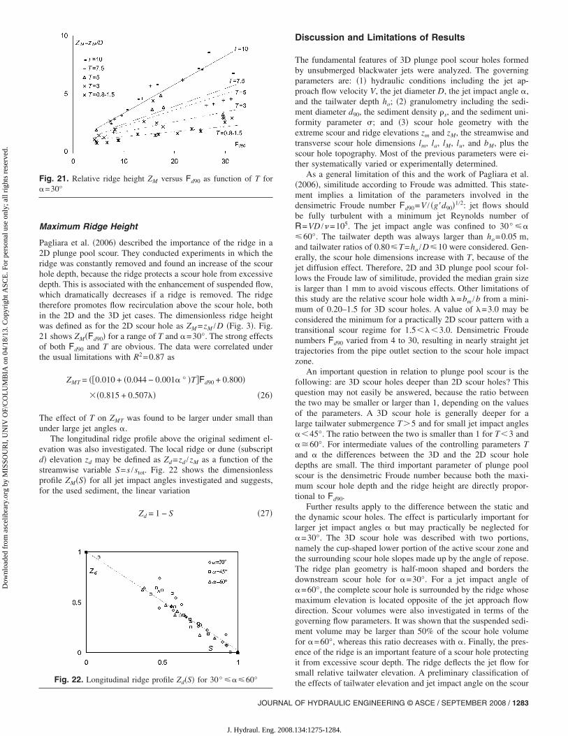
Maximum Ridge Height
Pagliara et al. �2006� described the importance of the ridge in a2D plunge pool scour. They conducted experiments in which theridge was constantly removed and found an increase of the scourhole depth, because the ridge protects a scour hole from excessivedepth. This is associated with the enhancement of suspended flow,which dramatically decreases if a ridge is removed. The ridgetherefore promotes flow recirculation above the scour hole, bothin the 2D and the 3D jet cases. The dimensionless ridge heightwas defined as for the 2D scour hole as ZM =zM /D �Fig. 3�. Fig.21 shows ZM�Fd90� for a range of T and �=30°. The strong effectsof both Fd90 and T are obvious. The data were correlated underthe usual limitations with R2=0.87 as
ZMT = ��0.010 + �0.044 − 0.001� ° �T�Fd90 + 0.800�
�0.815 + 0.507�� �26�
The effect of T on ZMT was found to be larger under small thanunder large jet angles �.
The longitudinal ridge profile above the original sediment el-evation was also investigated. The local ridge or dune �subscriptd� elevation zd may be defined as Zd=zd /zM as a function of thestreamwise variable S=s /stot. Fig. 22 shows the dimensionlessprofile ZM�S� for all jet impact angles investigated and suggests,for the used sediment, the linear variation
Zd = 1 − S �27�
Fig. 21. Relative ridge height ZM versus Fd90 as function of T for�=30°
Fig. 22. Longitudinal ridge profile Zd�S� for 30° �60°
JOURNAL
J. Hydraul. Eng. 2008.1
Discussion and Limitations of Results
The fundamental features of 3D plunge pool scour holes formedby unsubmerged blackwater jets were analyzed. The governingparameters are: �1� hydraulic conditions including the jet ap-proach flow velocity V, the jet diameter D, the jet impact angle �,and the tailwater depth ho; �2� granulometry including the sedi-ment diameter d90, the sediment density �s, and the sediment uni-formity parameter �; and �3� scour hole geometry with theextreme scour and ridge elevations zm and zM, the streamwise andtransverse scour hole dimensions lm, la, lM, lu, and bM, plus thescour hole topography. Most of the previous parameters were ei-ther systematically varied or experimentally determined.
As a general limitation of this and the work of Pagliara et al.�2006�, similitude according to Froude was admitted. This state-ment implies a limitation of the parameters involved in thedensimetric Froude number Fd90=V / �g�d90�1/2: jet flows shouldbe fully turbulent with a minimum jet Reynolds number ofR=VD /�=105. The jet impact angle was confined to 30° �60°. The tailwater depth was always larger than ho=0.05 m,and tailwater ratios of 0.80T=ho /D10 were considered. Gen-erally, the scour hole dimensions increase with T, because of thejet diffusion effect. Therefore, 2D and 3D plunge pool scour fol-lows the Froude law of similitude, provided the median grain sizeis larger than 1 mm to avoid viscous effects. Other limitations ofthis study are the relative scour hole width �=bm /b from a mini-mum of 0.20–1.5 for 3D scour holes. A value of �=3.0 may beconsidered the minimum for a practically 2D scour pattern with atransitional scour regime for 1.5���3.0. Densimetric Froudenumbers Fd90 varied from 4 to 30, resulting in nearly straight jettrajectories from the pipe outlet section to the scour hole impactzone.
An important question in relation to plunge pool scour is thefollowing: are 3D scour holes deeper than 2D scour holes? Thisquestion may not easily be answered, because the ratio betweenthe two may be smaller or larger than 1, depending on the valuesof the parameters. A 3D scour hole is generally deeper for alarge tailwater submergence T�5 and for small jet impact angles��45°. The ratio between the two is smaller than 1 for T�3 and��60°. For intermediate values of the controlling parameters Tand � the differences between the 3D and the 2D scour holedepths are small. The third important parameter of plunge poolscour is the densimetric Froude number because both the maxi-mum scour hole depth and the ridge height are directly propor-tional to Fd90.
Further results apply to the difference between the static andthe dynamic scour holes. The effect is particularly important forlarger jet impact angles � but may practically be neglected for�=30°. The 3D scour hole was described with two portions,namely the cup-shaped lower portion of the active scour zone andthe surrounding scour hole slopes made up by the angle of repose.The ridge plan geometry is half-moon shaped and borders thedownstream scour hole for �=30°. For a jet impact angle of�=60°, the complete scour hole is surrounded by the ridge whosemaximum elevation is located opposite of the jet approach flowdirection. Scour volumes were also investigated in terms of thegoverning flow parameters. It was shown that the suspended sedi-ment volume may be larger than 50% of the scour hole volumefor �=60°, whereas this ratio decreases with �. Finally, the pres-ence of the ridge is an important feature of a scour hole protectingit from excessive scour depth. The ridge deflects the jet flow forsmall relative tailwater elevation. A preliminary classification of
the effects of tailwater elevation and jet impact angle on the scourOF HYDRAULIC ENGINEERING © ASCE / SEPTEMBER 2008 / 1283
34:1275-1284.

Dow
nloa
ded
from
asc
elib
rary
.org
by
MIS
SOU
RI,
UN
IV O
F/C
OL
UM
BIA
on
04/1
8/13
. Cop
yrig
ht A
SCE
. For
per
sona
l use
onl
y; a
ll ri
ghts
res
erve
d.
hole features was given. The present research adds to the previouswork on the plane scour hole characteristics and may be useful inhydraulic engineering design.
Conclusions
This work relates to the spatial or 3D behavior of plunge poolscour holes. It may be considered an expansion of a previouswork relating to plane or 2D scour holes. By assuming that theplunge pool is made up of a granular material, a number of effectswere investigated. These include: �1� maximum dynamic andstatic scour hole depths; �2� scour hole length and plan features;�3� scour hole origin relative to the jet trajectory; �4� scour holevolume plus suspended sediment volume during the dynamicscour action; and �5� ridge height and ridge geometry. A total ofalmost 300 laboratory tests were conducted resulting in expres-sions that account for the basic flow parameters involved inplunge pool scour. The main results were discussed and limitedagainst effects of scale and the basic parameter selection. Thisresearch and that previously presented by Pagliara et al. �2006�may be used for predicting the most salient features of both 2Dand 3D scour hole patterns.
Notation
The following symbols are used in this paper:B � b /D relative channel width;
Bm � bm /D relative scour hole width;b � channel width;
bm � maximum scour hole width;D � jet diameter;d � sediment diameter;
Fd � V / �g�d�1/2 densimetric particle Froudenumber;
Fu � Vu / �ghu�1/2 approach flow Froude number;g � gravitational acceleration;
g�= ��s−�� /��g � reduced gravitational acceleration;ho � tailwater depth above original sediment
elevation;L= l /D � dimensionless scour hole length;
l � axial scour length;Q � discharge;T � ho /D relative tailwater submergence;V � mean velocity;
Wm � nondimensional dynamic scour holevolume;
Wr � nondimensional ridge volume;Ws � nondimensional suspended sediment
volume;
wm � dynamic scour hole volume;1284 / JOURNAL OF HYDRAULIC ENGINEERING © ASCE / SEPTEMBER 2
J. Hydraul. Eng. 2008.1
wr � ridge volume;ws � suspended sediment volume;Xm � �x−xm� / laT dimensionless axial coordinate;XS � longitudinal scour hole symmetry
parameter;x � axial coordinate from scour hole beginning;
ZM � zM /D maximum relative ridge elevation;Zm � zm /D maximum dimensionless scour hole
depth;zM � maximum ridge elevation;zm � maximum scour hole depth;� � jet impact angle;� � jet air content;� � correction function for spatial scour hole;� � bm /b relative scour hole width;� � sediment nonuniformity parameter; and� � subtended angle of ridge plan.
Subscripts
a � distance from start to scour hole end;M � distance from scour hole start to ridge
maximum;m � distance from scour hole start to maximum
scour depth;s � static scour hole;T � 3D �or spatial� scour;u � distance from scour hole origin to ridge
end; andW � water.
References
Anderson, C. L., and Blaisdell, F. W. �1982�. “Plunge pool energy dissi-pators for pipe spillways.” Proc., Conf. on Applying Research to Hy-draulic Practice, P. E. Smith, ed., ASCE, New York, 289–298.
Bormann, N. E., and Julien, P. Y. �1991�. “Scour downstream of grade-control structures.” J. Hydraul. Eng., 117�5�, 579–594.
Canepa, S., and Hager, W. H. �2003�. “Effect of air jet content on plungepool scour.” J. Hydraul. Eng., 128�5�, 358–365.
Mih, W. C. �1982�. “Scouring effects of water jets impinging on non-uniform streambeds.” Proc., Conf. on Applying Research to HydraulicPractice, P. E. Smith, ed., ASCE, New York, 270–279.
Mih, W. C., and Kabir, J. �1983�. “Impingement of water jets on nonuni-form streambeds.” J. Hydraul. Eng., 109�4�, 536–548.
Pagliara, S., Hager, W. H., and Minor, H.-E. �2004�. “Plunge pool scourin prototype and laboratory.” Int. Conf. on Hydraulics of Dams andRiver Structures, Balkema, Lisse, The Netherlands, 165–172.
Pagliara, S., Hager, W. H., and Minor, H.-E. �2006�. “Hydraulics of planeplunge pool scour.” J. Hydraul. Eng. 132�5�, 450–461.
Rajaratnam, N. �1980�. “Erosion by circular wall jets in cross flow.”J. Hydr. Div., 106�11�, 1867–1883.
Rajaratnam, N., and Berry, B. �1977�. “Erosion by circular turbulent wall
jets.” J. Hydraul. Res., 15�3�, 277–289.008
34:1275-1284.