hydraulic turbines - yozmen.ktu.edu.tryozmen.ktu.edu.tr/files/hes_2.pdf · hydraulics and hydraulic...
TRANSCRIPT

Hydraulics and Hydraulic Machines
Dr. M.N. Shesha Prakash, Professor, J .N.N. C ollege of Engineering, Shimoga 1
HYDRAULIC TURBINESIntroduction:
The device which converts hydraulic energy into mechanical energy or
vice versa is known as Hydraulic Machines. The hydraulic machines
which convert hydraulic energy into mechanical energy are known as
Turbines and that convert mechanical energy into hydraulic energy is
known as Pumps.
Fig. shows a general layout of a hydroelectric plant.
Animation as in the PPT
Hg
hL
H
PenstockTurbine
Tailrace
Headrace
HeadRace
Tail Race
Hg
H
hL

Hydraulics and Hydraulic Machines
Dr. M.N. Shesha Prakash, Professor, J .N.N. C ollege of Engineering, Shimoga 2
It consists of the following:
1. A Dam constructed across a river or a channel to store water. The
reservoir is also known as Headrace.
2. Pipes of large diameter called Penstocks which carry water under
pressure from storage reservoir to the turbines. These pipes are
usually made of steel or reinforced concrete.
3. Turbines having different types of vanes or buckets or blades
mounted on a wheel called runner.
4. Tailrace which is a channel carrying water away from the turbine
after the water has worked on the turbines. The water surface in the
tailrace is also referred to as tai lrace.
Important Terms:
Gross Head (Hg): It is the vertical difference between headrace and
tailrace.
Net Head:(H): Net head or effective head is the actual head available
at the inlet of the to work on the turbine.
H = Hg - hL
Where hL is the total head loss during the transit of water from the
headrace to tailrace which is mainly head loss due to friction, and is
given by
dg
VLfh f 2
4 2
Where f is the coefficient of friction of penstock depending on the
type of material of penstock
L is the total length of penstock
V is the mean flow velocity of water through the penstock
D is the diameter of penstock and
g is the acceleration due to gravity

Hydraulics and Hydraulic Machines
Dr. M.N. Shesha Prakash, Professor, J .N.N. C ollege of Engineering, Shimoga 3
R.P.S.P.m
TYPES OF EFFICIENCIES
Depending on the considerations of input and output, the efficiencies
can be classified as
(i) Hydraulic Efficiency
(ii) Mechanical Efficiency
(iii) Overall efficiency
(i) Hydraulic Efficiency: (h)
It is the ratio of the power
developed by the runner of a
turbine to the power supplied at the inlet
of a turbine. Since the power supplied is hydraulic, and the probable loss is between
the striking jet and vane it is rightly called hydraulic efficiency.
If R.P. is the Runner Power and W.P. is the Water Power
(ii) Mechanical Efficiency: (m)
It is the ratio of the power available at the shaft to the power developed by the
runner of a turbine. This depends on the slips and other mechanical problems that
will create a loss of energy between the runner in the annular area between
the nozzle and spear, the amount of water reduces as the spear is
pushed forward and vice-versa.
and shaft which is purely mechanical and hence mechanical
efficiency.
If S.P. is the Shaft Power
(02)
(iii) Overall Efficiency: ()
It is the ratio of the power available at the shaft to the power
supplied at the inlet of a turbine. As this covers overall problems of
losses in energy, it is known as overall efficienc y. This depends on
both the hydraulic losses and the slips and other mechanical problems
Inlet of turbine
Turbine Runner
Shaft
W.P.
R.P.h (01)

Hydraulics and Hydraulic Machines
Dr. M.N. Shesha Prakash, Professor, J .N.N. C ollege of Engineering, Shimoga 4
W.P.S.P.
that will create a loss of energy between the jet power supplied and
the power generated at the shaft available for coupling of the
generator.
(03)
From Eqs 1,2 and 3, we have
= h x m
Classification of Turbines
The hydraulic turbines can be classified based on type of energy at
the inlet , direction of flow through the vanes, head available at the
inlet , discharge through the vanes and specific speed. They can be
arranged as per the following table:
Turbine Type ofenergy
Head DischargeDirectionof flow
SpecificSpeedName Type
PeltonWheel
Impulse Kinetic
HighHead >250m to1000m
LowTangentialto runner
Low<35 Single jet
35 – 60 Multiple jet
FrancisTurbine Reaction
TurbineKinetic +Pressure
Medium60 m to150 m
MediumRadial flow Medium
60 to 300Mixed Flow
KaplanTurbine
Low< 30 m
High Axial FlowHigh
300 to 1000
As can be seen from the above table, any specific type can be
explained by suitable construction of sentences by selecting the other
items in the table along the row.

Hydraulics and Hydraulic Machines
Dr. M.N. Shesha Prakash, Professor, J .N.N. C ollege of Engineering, Shimoga 5
Penstock
Nozzle
Wheel Spear
PELTON WHEEL OR TURBINEPelton wheel, named after an eminent engineer, is an impulse turbine
wherein the flow is tangential to the runner and the available energy
at the entrance is completely kinetic energy. Further, it is preferred
at a very high head and low discharges with low specific speeds. The
pressure available at the inlet and the outlet is atmospheric.
The main components of a Pelton turbine are:
(i) Nozzle and flow regulating arrangement:
Water is brought to the hydroelectric plant si te through large
penstocks at the end of which there will be a nozzle, which converts
the pressure energy completely into
kinetic energy. This will convert the
liquid flow into a high-speed jet,
which strikes the buckets or
vanes mounted on the runner,
which in-turn rotates the runner of
the turbine. The amount of water striking the vanes is controlled by
the forward and backward motion of the spear. As the water is
flowing in the annular area between the annular area between the
Animation:(i) The water jet has to reduce
and increase as the spear isbrought forward andbackward
(ii) The wheel has to rotate as thejet strikes
Breaking jet

Hydraulics and Hydraulic Machines
Dr. M.N. Shesha Prakash, Professor, J .N.N. C ollege of Engineering, Shimoga 6
nozzle opening and the spear, the flow gets reduced as the spear
moves forward and vice-versa.
(ii) Runner with buckets:
Runner is a circular disk mounted on a shaft on the periphery of
which a number of buckets are fixed equally spaced as shown in
Fig. The buckets are made of cast-iron cast-steel, bronze or
stainless steel depending upon the head at the inlet of the turbine.
The water jet strikes the bucket on the splitter of the bucket and
gets deflected through () 160-1700 .
(iii ) Casing:
It is made of cast-iron or fabricated steel plates. The main function
of the casing is to prevent splashing of water and to discharge the
water into tailrace.
(iv) Breaking jet:
Even after the amount of water striking the buckets is comple tely
stopped, the runner goes on rotating for a very long time due to
inertia. To stop the runner in a short time, a small nozzle is
provided which directs the jet of water on the back of bucket with
which the rotation of the runner is reversed. This jet i s called as
breaking jet.
Buckets
Shaft
Runner

Hydraulics and Hydraulic Machines
Dr. M.N. Shesha Prakash, Professor, J .N.N. C ollege of Engineering, Shimoga 7
3 D Picture of a jet striking the splitter and getting split in to two parts
and deviating.
Velocity triangles for the jet striking the bucket
From the impulse-momentum theorem, the force with which the jet strikes
tthe bucket along the direction of vane is given by
Fx = rate of change of momentum of the jet along the direction of vane
motion
Fx = (Mass of water / second) x change in velocity along the x direction
Deflectionangle of jet
jet
Vane
u1 Vr1
V1=Vw1u
Deflection angle
Vr2
u2 Vw2
Vf2V2
Vf1=0

Hydraulics and Hydraulic Machines
Dr. M.N. Shesha Prakash, Professor, J .N.N. C ollege of Engineering, Shimoga 8
211 ww VVVa
211 ww VVVa
Work done per second by the jet on the vane is given by the product of
Force exerted on the vane and the distance moved by the vane in one
second
W.D./S = Fx x u
uVVVa ww 211
Input to the jet per second = Kinetic energy of the jet per second
312
1Va
Efficiency of the jet =ondInput
ondWorkdone
ondInput
ondOutput
sec/sec/
sec/sec/
3
121
211
Va
uVVVa ww
2
1
212V
VVu ww
From inlet velocity triangle, Vw1 = V1
Assuming no shock and ignoring frictional losses through the vane, we
have V r1 = V r2 = (V1 – u1)
In case of Pelton wheel, the inlet and outlet are located at the same radial
distance from the centre of runner and hence u1 = u2 = u
From outlet velocity triangle, we have Vw 2 = V r2 Cos - u2
= (V1 –u)Cos - u
uCosuVVVaFx 111
CosuVVaFx 111
Substituting these values in the above equation for efficiency, we have
2
1
11 cos2V
uuVVu
cos2
1121
uVuVV
u

Hydraulics and Hydraulic Machines
Dr. M.N. Shesha Prakash, Professor, J .N.N. C ollege of Engineering, Shimoga 9
cos12
121
uVV
u
The above equation gives the efficiency of the jet striking the vane in
case of Pelton wheel.
To obtain the maximum efficiency for a given jet velocity and vane angle,
from maxima-minima, we have
0ud
d
0cos12 2
121
uuVud
d
Vud
d
V1-2u = 0
or21V
u
i .e. When the bucket speed is maintained at half the velocity of the jet,
the efficiency of a Pelton wheel will be maximum. Substituting we get,
cos12
2
22max uu
u
u
cos121
max
From the above it can be seen that more the value of cos , more will be
the efficiency. Form maximum efficiency, the value of cos should be 1
and the value of should be 00 . This condition makes the jet to
completely deviate by 1800 and this, forces the jet striking the bucket to
strike the successive bucket on the back of it acting like a breaking jet .
Hence to avoid this situation, at least a small angle of =50 should be
provided.

Hydraulics and Hydraulic Machines
Dr. M.N. Shesha Prakash, Professor, J .N.N. C ollege of Engineering, Shimoga 10
Dec-06/Jan07
6 a.i)Sketch the layout of a PELTON wheel turbine showing the details
of nozzle, buckets and wheel when the turbine axis is horizontal(04)
ii) Obtain an expression for maximum-efficiency of an impulse turbine.
(06)
July 06
6 (a) With a neat sketch explain the layout of a hydro-electric plant (06)
(b) With a neat sketch explain the parts of an Impulse turbine. (06)
Jan 06
6 (a) What Is specific speed of turbine and state Its significance. (04)
(b) Draw a neat sketch of a hydroelectric plant and mention the
function of each component. (08)
Jan 05
6 (a) Classify the turbines based on head, specific speed and hydraulic
actions. Give examples for each. (06)
(b) What is meant by Governing of turbines? Explain with a neat sketch
the governing of an impulse turbine (06)
July 04
5 (a) Explain the classification of turbines. (08)

Hydraulics and Hydraulic Machines
Dr. M.N. Shesha Prakash, Professor, J .N.N. C ollege of Engineering, Shimoga 11
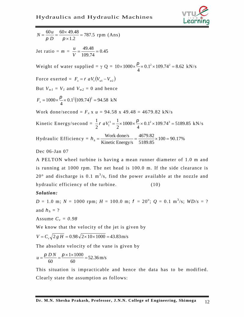
The head at the base of the nozzle of a Pelton wheel is 640 m. The outlet
vane angle of the bucket is 15 o . The relative velocity at the outlet is
reduced by 15% due to friction along the vanes. If the discharge at outlet
is without whirl find the ratio of bucket speed to the jet speed. If the jet
diameter is 100 mm while the wheel diameter is 1.2 m, find the speed of
the turbine in rpm, the force exerted by the jet on the wheel, the Power
developed and the hydraulic efficiency. Take Cv=0.97.
Solution:
H = 640 m; =15o ; V r1 = 0.85 V r2; Vw2 = 0; d = 100 mm; D = 1.2 m;
Cv = 0.97; Ku = ?; N = ?; Fx = ?; P = ?; h = ?
We know that the absolute velocity of jet is given by
74.10964010297.02 HgCV v m/s
Let the bucket speed be u
Relative velocity at inlet = V r1 = V1-u = 109.74-u
Relative velocity at outlet = V r2 = (1-0.15)V r1 = 0.85(109.74-u)
But V r2cos = u 0.85(109.74-u)cos15
Hence u = 49.48 m/s
But60
NDu
and hence
u1 Vr1
V1=Vw1u
Deflection angle
Vr2
u2Vw2=0
V2=Vf2
Vf1=0
Hydraulics and Hydraulic Machines
Dr. M.N. Shesha Prakash, Professor, J .N.N. C ollege of Engineering, Shimoga 12
5.7872.1
48.496060
D
uN rpm (Ans)
Jet ratio = m = 45.074.109
48.49
V
u
Weight of water supplied = Q = 62.874.1091.04
100010 22
kN/s
Force exerted = 211 wwx VVVaF
But Vw1 = V1 and Vw2 = 0 and hence
58.9474.1091.04
1000 22
xF kN
Work done/second = Fx x u = 94.58 x 49.48 = 4679.82 kN/s
Kinetic Energy/second = 189.85574.1091.04
10002
1
2
1 3231
Va kN/s
Hydraulic Efficiency = %17.9010085.5189
82.4679
Energy/sKinetic
done/sWorkh
Dec 06-Jan 07
A PELTON wheel turbine is having a mean runner diameter of 1.0 m and
is running at 1000 rpm. The net head is 100.0 m. If the side clearance is
20° and discharge is 0.1 m3 /s, find the power available at the nozzle and
hydraulic efficiency of the turbine. (10)
Solution:
D = 1.0 m; N = 1000 rpm; H = 100.0 m; = 20o; Q = 0.1 m3 /s; WD/s = ?
and h = ?
Assume Cv = 0.98
We know that the velocity of the jet is given by
m/s83.43100010298.02 HgCV v
The absolute velocity of the vane is given by
m/s36.5260
10001
60
NDu
This situation is impracticable and hence the data has to be modified.
Clearly state the assumption as follows:

Hydraulics and Hydraulic Machines
Dr. M.N. Shesha Prakash, Professor, J .N.N. C ollege of Engineering, Shimoga 13
Assume H = 700 m (Because it is assumed that the typing and seeing error
as 100 for 700)
Absolute velocity of the jet is given by
m/s96.11570010298.02 HgCV v
Power available at the nozzle is the given by work done per second
WD/second = Q H = g Q H = 1000x10x0.1x700 = 700 kW
Hydraulic Efficiency is given by
%07.96)20cos1(36.5296.11596.115
36.522cos1
2212
1
uVV
uh
July 06
A Pelton wheel has a mean bucket speed of 10 m/s with a jet of water
flowing at the rate of 700 lps under a head of 30 m. The buckets deflect
the jet through an angle of 160°. Calculate the power given by water to
the runner and the hydraulic efficiency of the turbine. Assume the
coefficient of nozzle as 0.98. (08)
Solution:
u = 10 m/s; Q = 0.7 m3 /s; = 180-160 = 20o; H = 30 m; Cv = 0.98;
WD/s = ? and h = ?
Assume g = 10m/s2
52.36 Vr1
V1=115.96 u
Deflection angle
Vr2
52.36 Vw2
Vf2V2
Vf1=0

Hydraulics and Hydraulic Machines
Dr. M.N. Shesha Prakash, Professor, J .N.N. C ollege of Engineering, Shimoga 14
m/s243010298.02 HgCV v
V r1 = V1-u = 24 – 10 = 14 m/s
Assuming no shock and frictional losses we have V r1 = V r2 = 14 m/s
Vw2 = V r2 Cos - u = 14 x Cos 20 – 10 = 3.16 m/s
We know that the Work done by the jet on the vane is given by
WD/s 21211 wwww VVuQuVVVa as Q = aV1
12.19016.324107.01000 kN-m/s (Ans)
IP/s = KE/s 201.6247.010002
1
2
1
2
1 221
31 VQVa kN-m/s
Hydraulic Efficiency = Output/ Input = 190.12/201.6 = 94.305%
It can also be directly calculated by the derived equation as
94.29%20cos1102424
102cos1
2212
1
uVV
uh (Ans)
Jan 06
A Pelton wheel has to develop 13230 kW under a net head of 800 m while
running at a speed of 600 rpm. If the coefficient of Jet Cy = 0.97, speed
ratio = 0.46 and the ratio of the Jet diameter is
1 /16 of wheel diameter. Calculate
i) Pitch circle diameter ii) the diameter of jet
iii) the quantity of water supplied to the wheel
10 Vr1
V1=24 u
Deflection angle
Vr2
10 Vw2
Vf2V2
Vf1=0

Hydraulics and Hydraulic Machines
Dr. M.N. Shesha Prakash, Professor, J .N.N. C ollege of Engineering, Shimoga 15
iv) the number of Jets required.
Assume over all efficiency as 85%. (08)
Solution:
P = 13239 kW; H = 800 m; N = 600 rpm; Cv = 0.97; = 0.46 (Speed ratio)
d/D = 1/16; o = 0.85; D = ?; d = ?; n = ?;
Assume g = 10 m/s2 and = 1000 kg/m3
We know that the overall efficiency is given by
85.0800100010
1013239 3
QHQ
P
Input
Outputo
Hence Q = 1.947 m3 /s (Ans)
Absolute velocity of jet is given by
m/s696.12280010297.02 HgCV v
Absolute velocity of vane is given by
186.5880010246.02 Hgu m/s
The absolute velocity of vane is also given by
60
NDu
and hence
mN
uD 85.1
600
186.586060
(Ans)
16
85.1d 115.625 mm (Ans)
Discharge per jet = 1.288696.122115625.044
22
Vdq m3 /s
No. of jets = 2288.1
947.1
q
Qn (Ans)
July 05
Design a Pelton wheel for a head of 80m. and speed of 300 RPM. The
Pelton wheel develops 110 kW. Take co-eficient of velocity= 0.98, speed
ratio= 0.48 and overall efficiency = 80%. (10)
Solution:
H = 80 m; N = 300 rpm; P = 110 kW; Cv = 0.98, Ku=0.48; o = 0.80

Hydraulics and Hydraulic Machines
Dr. M.N. Shesha Prakash, Professor, J .N.N. C ollege of Engineering, Shimoga 16
Assume g = 10 m/s2 and = 1000 kg/m3
We know that the overall efficiency is given by
8.080100010
10110 3
QHQ
P
Input
Outputo
Hence Q = 0.171875 m3 /s
Absolute velocity of jet is given by
m/s39.28010298.02 HgCV v
Absolute velocity of vane is given by
19.28010248.02 Hgu m/s
The absolute velocity of vane is also given by
60
NDu
and hence
mN
uD 22.1
300
19.26060
(Ans)
Single jet Pelton turbine is assumed
The diameter of jet is given by the discharge continuity equation
171875.02.3944
22 dVdQ
Hence d = 74.7 mm
The design parameters are
Single jet
Pitch Diameter = 1.22 m
Jet diameter = 74.7 mm
Jet Ratio = 32.160747.0
22.1
d
Dm
No. of Buckets = 0.5xm + 15 = 24
Jan 05
It is desired to generate 1000 kW of power and survey reveals that 450 m
of static head and a minimum flow of 0.3 m 3 /s are available. Comment
whether the task can be accomplished by installing a Pelton wheel run at
1000 rpm and having an overall efficiency of 80%.

Hydraulics and Hydraulic Machines
Dr. M.N. Shesha Prakash, Professor, J .N.N. C ollege of Engineering, Shimoga 17
Further, design the Pelton wheel assuming suitable data for coefficient of
velocity and coefficient of drag. (08)
Solution:
P = 1000 kW; H = 450 m; Q = 0.3 m3 /s; N = 1000 rpm; o = 0.8
Assume Cv = 0.98; Ku=0.45; = 1000 kg/m3 ; g = 10 m/s2
74.04503.0100010
101000 3
HQ
P
Input
Outputo
For the given condit ions of P, Q and H , i t is not possible to achieve the
desired efficiency of 80%.
To decide whether the task can be accomplished by a Pelton turbine
compute the specific speed N s
45
H
PNN s ;
where N is the speed of runner, P is the power developed in kW and H is
the head available at the inlet .
25.15450
10001000
45 sN <35
Hence the installation of single jet Pelton wheel is justified.
Absolute velocity of jet is given by
m/s97.9245010298.02 HgCV v
Absolute velocity of vane is given by
19.28010248.02 Hgu m/s
The absolute velocity of vane is also given by
60
NDu
and hence
mN
uD 22.1
300
19.26060
(Ans)
Single jet Pelton turbine is assumed
The diameter of jet is given by the discharge continuity equation

Hydraulics and Hydraulic Machines
Dr. M.N. Shesha Prakash, Professor, J .N.N. C ollege of Engineering, Shimoga 18
171875.02.3944
22 dVdQ
Hence d = 74.7 mm
The design parameters are
Single jet
Pitch Diameter = 1.22 m
Jet diameter = 74.7 mm
Jet Ratio = 32.160747.0
22.1
d
Dm
No. of Buckets = 0.5xm + 15 = 24
July 04
A double jet Pelton wheel develops 895 MKW with an overall efficiency
of 82% under a head of 60m. The speed ratio = 0.46, jet ratio = 12 and the
nozzle coefficient = 0.97. Find the jet diameter, wheel diameter and wheel
speed in RPM. (12)
Solution:
No. of jets = n = 2; P = 895 kW; o = 0.82; H = 60 m; Ku = 0.46; m = 12;
Cv = 0.97; D = ?; d = ?; N = ?
We know that the absolute velocity of jet is given by
6.336010297.02 HgCV v m/s
The absolute velocity of vane is given by
93.156010246.02 HgKu u m/s
Overall efficiency is given by
HQ
Po
and hence 819.16082.01010
108953
3
H
PQ
m3 /s
Discharge per jet = 9095.02
819.1
n
Qq m3 /s
From discharge continuity equation, discharge per jet is also given by
md
dV
dq
186.0
9095.06.3344
22

Hydraulics and Hydraulic Machines
Dr. M.N. Shesha Prakash, Professor, J .N.N. C ollege of Engineering, Shimoga 19
Further, the jet ratiod
Dm 12
Hence D = 2.232 m
Also60
NDu
and hence 136
232.2
93.156060
D
uN rpm
Note: Design a Pelton wheel: Width of bucket = 5d and depth of bucket is
1.2d
The following data is related to a Pelton wheel:
Head at the base of the nozzle = 80m; Diameter of the jet = 100 mm;
Discharge of the nozzle = 0.3m3 /s; Power at the shaft = 206 kW; Power
absorbed in mechanical resistance = 4.5 kW. Determine (i) Power lost in
the nozzle and (ii) Power lost due to hydraulic resistance in the runner.
Solution:
H = 80 m; d = 0.1m; a = ¼ d2 = 0.007854 m2 ; Q = 0.3 m3 /s; SP = 206
kW; Power absorbed in mechanical resistance = 4.5 kW.
From discharge continuity equation, we have,
Q = a x V = 0.007854 x V 0.3
V = 38.197 m/s
Power at the base of the nozzle = g Q H
= 1000 x 10 x 0.3 x 80 = 240 kW
Power corresponding to the kinetic energy of the jet = ½ a V3
= 218.85 kW
(i) Power at the base of the nozzle = Power of the jet + Power lost in the nozzle
Power lost in the nozzle = 240 218.85 = 21.15 kW (Ans)
(ii) Power at the base of the nozzle = Power at the shaft + Power lost in the
(nozzle + runner + due to mechanical
resistance)
Power lost in the runner = 240 – (206 + 21.15 + 4.5) = 5.35 kW (Ans)
Hydraulics and Hydraulic Machines
Dr. M.N. Shesha Prakash, Professor, J .N.N. C ollege of Engineering, Shimoga 20
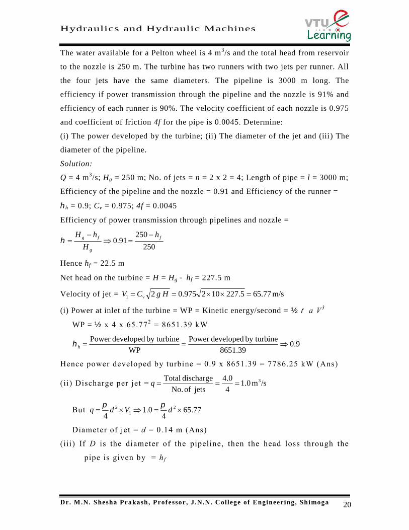
The water available for a Pelton wheel is 4 m3/s and the total head from reservoir
to the nozzle is 250 m. The turbine has two runners with two jets per runner. All
the four jets have the same diameters. The pipeline is 3000 m long. The
efficiency if power transmission through the pipeline and the nozzle is 91% and
efficiency of each runner is 90%. The velocity coefficient of each nozzle is 0.975
and coefficient of friction 4f for the pipe is 0.0045. Determine:
(i) The power developed by the turbine; (ii) The diameter of the jet and (iii) The
diameter of the pipeline.
Solution:
Q = 4 m3/s; Hg = 250 m; No. of jets = n = 2 x 2 = 4; Length of pipe = l = 3000 m;
Efficiency of the pipeline and the nozzle = 0.91 and Efficiency of the runner =
h = 0.9; Cv = 0.975; 4f = 0.0045
Efficiency of power transmission through pipelines and nozzle =
250
25091.0 f
g
fg h
H
hH
Hence hf = 22.5 m
Net head on the turbine = H = Hg hf = 227.5 m
Velocity of jet = m/s65.775.227102975.021 HgCV v
(i) Power at inlet of the turbine = WP = Kinetic energy/second = ½ a V3
WP = ½ x 4 x 65.772 = 8651.39 kW
9.08651.39
by turbinedevelopedPower
WP
by turbinedevelopedPowerh
Hence power developed by turbine = 0.9 x 8651.39 = 7786.25 kW (Ans)
(ii) Discharge per jet = /sm0.14
0.4
jetsofNo.
dischargeTotal 3q
But 77.654
0.14
21
2 dVdq
Diameter of jet = d = 0.14 m (Ans)
(iii) If D is the diameter of the pipeline, then the head loss through the
pipe is given by = h f

Hydraulics and Hydraulic Machines
Dr. M.N. Shesha Prakash, Professor, J .N.N. C ollege of Engineering, Shimoga 21
5
22
32
4
D
QLf
Dg
VLfh f (From Q=aV)
5.223
430000045.05
2
D
h f
Hence D = 0.956 m (Ans)
The three jet Pelton wheel is required to generate 10,000 kW under a net
head of 400 m. The blade at outlet is 15 o and the reduction in the relative
velocity while passing over the blade is 5%. If the overall efficiency of
the wheel is 80%, C v = 0.98 and the speed ratio = 0.46, then find: (i) the
diameter of the jet, (ii) total flow (ii i) the force exerted by a jet on the
buckets (iv) The speed of the runner.
Solution:
No of jets = 3; Total Power P = 10,000 kW; Net head H = 400 m; Blade
angle = = 15o; Vr2 = 0.95 Vr1 ; Overall efficiency = o = 0.8; Cv = 0.98;
Speed ratio = Ku = 0.45; Frequency = f = 50 Hz/s.
We know that400101000
10000,108.0
3
QHQg
Po
Q = 3.125 m3 /s (Ans)
Discharge through one nozzle = /sm042.13
125.3 3n
Velocity of the jet = /sm65.8740010298.02 31 HgCV v
But 65.874
042.14
21
2 dVdq
d = 123 mm (Ans)
Velocity of the Vane = /sm14.4140010246.02 3 HgKu u
Vr1 = (V1u1)=87.6541.14 = 46.51 m/s
Vr2 = 0.95 Vr1 = 0.95 x 46.51 = 44.18 m/s
Vw1 = V1 = 87.65 m/s
Vw2 = Vr2 cos u2 = 44.18 cos 1541.14 = 1.53 m/s
Force exerted by the jet on the buckets = Fx = q(Vw1+Vw2)

Hydraulics and Hydraulic Machines
Dr. M.N. Shesha Prakash, Professor, J .N.N. C ollege of Engineering, Shimoga 22
Fx = 1000 x 1.042 (87.65+1.53) = 92.926 kN (Ans)
Jet ratio = (Assumed)10d
Dm
D = 1.23 m
60
NDu
Hence23.1
14.416060
D
uN =638.8 rpm (Ans)