hydraulic rotary actuator - rimagroup.com · rima is specialized in manufacturing hydraulic vane...
TRANSCRIPT

Working on ideas handling
Hydraulic
Rotary actuator
More than 35 years of experience! Thanks to over 35 years of experience in this field, we have been manufacturing hydraulic rotary actuators for a wide range of application. This allows us to design actuators made in series or customized models in order to suit many application requirements.
Other production of RIMA Storm brakes for crane Hydraulic system for: ▪ Container crane ▪ Jib cranes ▪ Double lever cranes ▪ Cranes and machines for
material handling ▪ Off-shore applications ▪ Steelworks applications ▪ Electrical power supply
line: Cobra® ▪ Hydraulic rotary joints
Rima S.r.l. a socio unico
Società sottoposta all'attività di direzione e coordinamento da parte di PINTSCH BUBENZER Gmbh Via Fermi 255 – 21042 Caronno Pertusella (Va) Italy Phone: +39 02 9650694 Fax +39 02 9657860 E-mail: [email protected]

The system The hydraulic rotary actuator is a device which transform hydraulic power (pressure and flow) in mechanical power: torque and angular speed. They are used for alternative movements with a limited rotation angle: max 260°. The simplicity of construction of our actuators allows to obtain very high mechanical efficiency value in comparison to the traditional “hydraulic cylinder-rack” system. The hydraulic rotary actuators Rima have the advantages of a small overall dimensions, a stability of the supplied torque during the run and also a cheap price. The absence of transmission devices between rotary actuator and utilizer and the mechanical efficiency allow moreover to obtain a very exact torque value. Our rotary actuators are the ideal choice for all the most advanced applications of automation where high reliability and quality of executions are needed. The rotary actuators can be positively applied instead of quick motors plus reducers; the elimination of an element (the reducer) cut down the costs, take off the maintenance of an element and usually allows to reduce dimensions.
Working on idea handling
www.rimagroup.com
▪ THE SYSTEM
Page 1

Applications With more than 35 years of experience, we have realized rotary actuators for every kind of application. The most frequent applications are:
▪ Back hoes ▪ Industrial automation machines ▪ Crane spreaders (flipper movements) ▪ Presses ▪ Hydraulic lift ▪ Injection moulding machines
Our technical department can find the ideal solution for your need, with standard solutions or special executions.
Construction system The actuator can be single or double vane. The single vane allows a greater rotation angle (260°), the double vane determines the reduction of the rotation angle (90°), but increases considerably the torque supplied, external overall dimensions being equal. The construction elements are: (see figure):
1. Casting rotary actuator’s body 2. Head 3. Bushing 4. Dust seal 5. Shaft seal 6. Seal 7. Shaft (grooved or hollow with tongue) 8. Moving vane 9. Moving vane seals 10. Fixed vane 11. Fixed vane seals
Working on idea handling
www.rimagroup.com
▪ APPLICATIONS ▪ CONSTRUCTION
SYSTEM
Page 2

Standard actuators must not reach the end of stroke. Therefore external stop devices and / or limit switches must be foreseen. In case of need to reach the end of stroke, particular indication has to be given at request of quotation. For tech. Expl. Please contact our Technical Dept. The standard version of rotary actuator can bear limited radial and axial loads. In case of high radial and/or axial loads, please refer to our Technical Dept.
Installation rules and functioning of hydraulic circuit In the hydraulic circuit it is convenient to foresee “anti-shock” valves which avoid pressure peaks in the rotary actuator. The suggested circuit is the one shown in figure A. Assembly The actuator can be fixed with feet or flange. In case of flange, the two holes not threaded must be bored during assembly, in order to receive the centering pins with force fit. The torque of the rotary actuator must not be transmitted to the fixing screws. The shaft is smooth on a side and grooved on the other side. The execution with hollow shaft foreseen a tongue. We suggest the execution with oil connections on the upper part, to facilitate air draining. Median position (see figure B) In the execution with output shaft: - single vane: position the arrow on the shaft down side. - double vane: position the arrow on the shaft on right side. In the execution with hollow shaft: - position the grooves on up side. Filtering For a correct functioning, an oil filtering of at least 25 micron is required
figure A
figure B
Working on ideas handling
www.rimagroup.com
▪ INSTALLATION AND FUNCTIONING
Page 3

Hydraulic oil In the standard execution it is foreseen the use of normal oil with viscosity between 1,8 and 50°E (between 10 and 370 cSt). Upon request can be used seal suitable for phosphoric ester or for water. Working temperature From -20°C to +80°C (with Teflon seals). Different temperatures upon request.
Technical characteristics Working pressure: 210 bar Torques: from 100 to 80000 Nm Angle: single vane 260° double vane 90° Leakages: see figure C Efficiency: with Teflon seals : Single vane ≈ 90% Double vane ≈ 95% The torque values take into account the efficiency.
Calculation for pump delivery: Qt = t
V
max
60
α
α
Qt = theoretic pump delivery (l/min.) V = displacement (l) α = required angle
α max = actuator max angle
t = required time (seconds) to carry out the angle α
effectiveQ = Qt + leakages (see diagram figure C)
figure C
Working on ideas handling
www.rimagroup.com
▪ TECHNICAL CHARACTERISTIC
Page 4

RIMA codes
Types and main data
Special executions RIMA can make a wide range of customization and fittings to make the actuators suitable to several applications. Here after the most common special executions:
▪ Actuators suitable to bear radial and /or axial loads ▪ Actuator with a rotation angle different from standard ▪ Actuator with holes, shafts different from standard ▪ Actuator for high speed
Minimum quantities are required for special executions.
Our experience There are many types of actuators: pneumatic, hydraulic, vane, piston and ground rack. RIMA is specialized in manufacturing hydraulic vane rotary actuators. Peculiarity of this kind of actuator is high efficiency and minimum effect Slip-stick. Our know how makes our actuator the best solution for applications in which high torque and defined angle are required. RIMA actuators have a max. torque from 1.200Nm to 83.000 Nm, at 3.000 Psi (210 Bar) according to size.
Working on ideas handling
www.rimagroup.com
▪ SPECIAL EXECUTION
▪ OUR EXPERIENCE ▪ RIMA CODES
Page 5
R6 030 AS S P N
Rotary actuators
Displacement
AS = protruding
shaft S = single vane P = feet
N = standard execution
AC = hollow shaft
D = double vane F = flange S = special execution
Type Shaft Rotation
angle Torque at
210 bar (Nm) Displacement
(cm³/°)
Weight without oil
(kg)
R6-030-ASS Protruding 260 1200 1.15 20
R6-022-ASD “ 90 2500 2.44 21
R6-078-ASS “ 260 3000 3 65
R6-100-ASS “ 260 3800 3.85 50
R6-070-ASD “ 90 8000 7.78 51
R6-300-ASS “ 260 11600 11.54 160
R6-214-ASD “ 90 24500 23.78 162
R6-1000-ASS “ 260 39000 38.46 440
R6-730-ASD “ 90 83000 81.11 450
R6-055-ACS Hollow 260 2000 2.12 30
R6-078-ACS “ 260 3000 3 35
R6-125-ACS “ 260 4800 4.81 43
Working on ideas handling
www.rimagroup.com
▪ SPREADER APPLICATIONS
Page 6
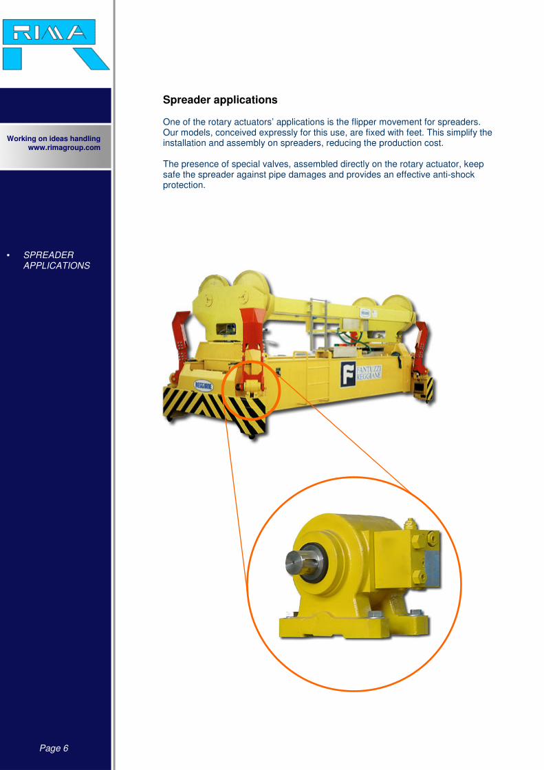
Spreader applications One of the rotary actuators’ applications is the flipper movement for spreaders. Our models, conceived expressly for this use, are fixed with feet. This simplify the installation and assembly on spreaders, reducing the production cost. The presence of special valves, assembled directly on the rotary actuator, keep safe the spreader against pipe damages and provides an effective anti-shock protection.
Pag
e 7
▪ T
EC
HN
ICA
L
CH
AR
AT
TE
RIS
TIC
S
Wo
rkin
g o
n id
eas h
an
dlin
g
ww
w.rim
ag
rou
p.c
om
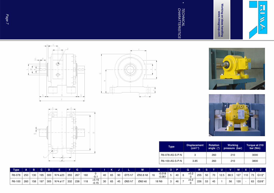
Type A B C D E F G H I K J L M N O P Q R S T U V W X Y Z
R6-078 250 130 195 300 N°4 ø23 355 267 160 0
40 65 90 Ø75 h7 Ø50.8 h8 16 -0.018
5 40 6 +0.2
255 50 70 12.5 88.5 127 110 73 G1/2” -0.1 -0.061 0
R6-100 260 158 197 305 N°4 ø17 332 238 118 +0.15
30 65 45 Ø65 h7 Ø60 k6 18 N9 3 46 7 +0.2
226 53 45 1 56 120 - 63 G3/8” -0.15 0
Type Displacement
(cm³/°) Rotation angle (°)
Working pressure (bar)
Torque at 210 bar (Nm)
R6-078-AS-S-P-N 3 260 210 3000
R6-100-AS-S-P-N 3.85 260 210 3800

Pag
e 8
▪ T
EC
HN
ICA
L
CH
AR
AC
TE
RIS
TIC
S
Wo
rkin
g o
n id
eas h
an
dlin
g
ww
w.rim
ag
rou
p.c
om
Type A B C D E F G H I K J L M N O P Q R S T U V W X
R6-078 212 210 52 UNI 221 Ø 55 h7 40 180 N°3 M12X25 N°2 Ø15x32 75 h7 30° 92 h7 6 11 17.5 63.5 60 73 G1/2” 127 112 M12x25 - 330 60
Type Displacement
(cm³/°) Rotation angle (°)
Working pressure (bar)
Torque at 210 bar (Nm)
R6-078-AS-S-F-N 3 260 210 3000

Pag
e 9
▪ T
EC
HN
ICA
L
CH
AR
AC
TE
RIS
TIC
S
Wo
rkin
g o
n id
eas h
an
dlin
g
ww
w.rim
ag
rou
p.c
om
Type A B C D E F G H I K J L M N O P Q R S T U V W X
R6-022 166 184 36 UNI 221 Ø40 h8 25 105 N°4 ø12H7x20 N°8 M12x20 Ø45 h7 30° Ø58 h8 9 17 17 36 35 45 G1/4” 85 86 - - 270 43
R6-030 166 175 36 UNI 221 Ø40 h8 25 105 N°4 ø12H7x20 N°8 M12x20 Ø45 h7 30° Ø58 h8 9 12.5 12.5 36 35 45 G1/4” 85 86 - - 270 47.5
R6-070 235 242 52 UNI 221 Ø55 h7 40 143 N°4 ø15H7x32 N°8 M14x30 Ø65 h7 30° Ø85 h8 10 19 19 46 45 63 G3/8” 120 120 - - 362 60
R6-100 235 242 52 UNI 221 Ø55 h7 40 143 N°4 ø15H7x32 N°8 M14x30 Ø65 h7 30° Ø85 h8 10 19 19 46 45 63 G3/8” 120 120 - - 362 60
R6-214 350 304 82 UNI 221 Ø85 h7 75 225 N°4 ø22H7x47 N°8 M20x35 Ø95 h7 30° Ø125 h8 17 26 26 51 45 95 G3/4” 185 180 - - 510 103
R6-300 350 304 82 UNI 221 Ø85 h7 75 225 N°4 ø22H7x47 N°8 M20x35 Ø95 h7 30° Ø125 h8 17 26 26 51 45 95 G3/4” 185 180 - - 510 103
R6-730 520 450 150 UNI 221 Ø135 h8 145 350 N°4 ø31,5H7x50 N°8 M27x50 Ø155 h7 30° Ø280 h8 25 45 45 150 100 140 G1” 230 270 - - 780 103
R6-1000 520 450 150 UNI 221 Ø135 h8 145 350 N°4 ø31,5H7x50 N°8 M27x50 Ø155 h7 30° Ø280 h8 25 45 45 150 100 140 G1” 230 270 - - 780 165
Type Displacement
(cm³/°) Rotation angle (°)
Working pressure
(bar)
Torque at 210 bar
(Nm)
R6-022-AS-D-F-N 2.44 90 210 2500
R6-070-AS-D-F-N 7.78 90 210 8000
R6-214-AS-D-F-N 23.78 90 210 24500
R6-730-AS-D-F-N 81.11 90 210 83000
Type Displacement
(cm³/°) Rotation angle (°)
Working pressure
(bar)
Torque at 210 bar
(Nm)
R6-030-AS-S-F-N 1.15 260 210 1200
R6-100-AS-S-F-N 3.85 260 210 3800
R6-300-AS-S-F-N 11.54 260 210 11600
R6-1000-AS-S-F-N 38.4 260 210 39000

Pag
e 1
0
▪ T
EC
HN
ICA
L
CH
AR
AC
TE
RIS
TIC
S
Wo
rkin
g o
n id
eas h
an
dlin
g
ww
w.rim
ag
rou
p.c
om
Type Displacement (cm³/°) Rotation angle (°) Working pressure (bar) Torque at 210 bar (Nm)
R6-055-AC-S-F-N 2.12 260 210 2000
R6-078-AC-S-F-N 3 260 210 3000
R6-125-AC-S-F-N 4.81 260 210 4800
Type A B C D E F G H I K J L M N O P Q R S T U V
R6-055 213 185 50 H7 53.8 0
14 H8 180 N°3 M12X25 N°2 Ø15H7/32 75 h7 30° 92 h7 6 11 17.5 63.5 50 73 G1/2” 127 111 - - +0.2
R6-078 213 210 50 H7 53.8 0
14 H8 180 N°3 M12X25 N°2 Ø15H7/32 75 h7 30° 92 h7 6 11 17.5 63.5 60 73 G1/2” 127 112 - - +0.2
R6-125 213 255 50 H7 53.8 0
14 H8 180 N°3 M12X25 N°2 Ø15H7/32 75 h7 30° 92 h7 6.35 5.8 18.5 63.5 60 73 G1/2” 127 112 - - +0.2