hydraulic motor/pump - hanfab slashers · hydraulic motor/pump ... when requesting a bearing life...
TRANSCRIPT

Hydraulic Motor/PumpSeries F11/F12 Fixed Displacement

2 Parker HannifinPump and Motor DivisionTrollhättan, Sweden
Hydraulic motor/pumpSeries F11/F12
Catalogue HY30-8249/US
Conversion factors1 kg ................................................................. 2.20 lb1 N ............................................................... 0.225 lbf1 Nm ......................................................... 0.738 lbf ft1 bar ..............................................................14.5 psi1 l ......................................................0.264 US gallon1 cm3 .......................................................0.061 cu in1 mm ............................................................. 0.039 in1°C .............................................................5/9(°F-32)1 kW .............................................................. 1.34 hp
Conversion factors1 lb ............................................................... 0.454 kg1 lbf ................................................................4.448 N1 lbf ft ..........................................................1.356 Nm1 psi ......................................................0.068948 bar1 US gallon ..................................................... 3.785 l1 cu in .....................................................16.387 cm3
1 in ............................................................... 25.4 mm1°F ............................................................9/5°C + 321 hp...........................................................0.7457 kW
Torque (M)
M = [Nm]
Basic formulas for hydraulic motors
Flow (q)
q = [l/min]
Power (P)
P = [kW]
D x n 1000 x ηv
D x ∆p x ηhm 63
q x ∆p x ηt
600
D - displacement [cm3/rev] n - shaft speed [rpm] ηv - volumetric efficiency ∆p - differential pressure [bar] (between inlet and outlet) ηhm - mechanical efficiency ηt - overall efficiency (ηt = ηv x ηhm)
Torque (M)
M = [Nm]
Basic formulas for hydraulic pumps
Flow (q)
q = [l/min]
Power (P)
P = [kW]
D x n x ηv
1000
D x ∆p 63 x ηhm
q x ∆p 600 x ηt
D - displacement [cm3/rev] n - shaft speed [rpm] ηv - volumetric efficiency ∆p - differential pressure [bar] (between inlet and outlet) ηhm - mechanical efficiency ηt - overall efficiency (ηt = ηv x ηhm)
FAILURE OR IMPROPER SELECTION OR IMPROPER USE OF THE PRODUCTS DESCRIBED HEREIN OR RELATED ITEMS CAN CAUSE DEATH, PERSONAL INJURY AND PROPERTY DAMAGE.This document and other information from Parker-Hannifin Corporation, its subsidiaries and authorized distributors provide product or system options for further investigation by users having technical expertise.
The user, through its own analysis and testing, is solely responsible for making the final selection of the system and components and assuring that all performance, endurance, maintenance, safety and warning requirements of the application are met. The user must analyze all aspects of the application, follow applicable industry standards, and follow the information concerning the product in the current product catalog and in any other materials provided from Parker or its subsidiaries or authorized distributors.
To the extent that Parker or its subsidiaries or authorized distributors provide component or system options based upon data or specifications provided by the user, the user is responsible for determining that such data and specifications are suitable and sufficient for all applications and reasonably foreseeable uses of the components or systems.
Offer of SalePlease contact your Parker representation for a detailed ”Offer of Sale”.
WARNING – USER RESPONSIBILITY

3 Parker HannifinPump and Motor DivisionTrollhättan, Sweden
Hydraulic motor/pumpSeries F11/F12
Catalogue HY30-8249/USContent
1
2
3
4
5
General product information General product informationGeneral information and design, Bearing life, F11/F12 Fan motors, Pages 4 - 7 F11/F12 in saw motor applications, Parker Power Boost
Series F11 F11Bent axis piston pump/motor with fixed displacement Pages 8 - 37
Series F12 F12Bent axis piston pump/motor with fixed displacement Pages 38 - 57
Accessories AccessoriesFlushing valves, FV13 flushing valve block, Integrated pressure relief valve, SR pressure Pages 58 - 66 relief/anticavitation valve block, SV pressure relief valve block, Speed sensor, BLA Boost units
Installation and start up information Installation and start up informationF11, F12 Pages 67 - 69

4 Parker HannifinPump and Motor DivisionTrollhättan, Sweden
Hydraulic motor/pumpSeries F11/F12
Catalogue HY30-8249/US
Series F11F11 is a bent-axis, fixed displacement motor/pump. It can be used in numerous applications in both open and closed loop circuits.The F11 series is available in sizes 5, 6, 10, 12, 14 and 19 cc (0.3 to 1.16 cu in/rev).
F11 Features (6090 psi)
and continuous operating pressure up to 350 bar (5075 psi)
the rotating parts, the F11 tolerates very high speeds, up to 14000 rpm
Series F12F12 is a bent-axis, fixed displacement motor/pump. It can be used in numerous applications in both open and closed loop circuits.The F12 series is available in sizes 30, 40, 60, 80, 90, 110, 125, 150 and 250 cc (1.83 to 14.8 cu in/rev).
F12 Features(6960 psi)
and continuous operating pressure up to 420 bar (6090 psi)
and smooth motor operation
General Features
thermal shock resistance
add up to a very robust design with long service life and, above all, proven reliability.
pump.
noise, available with left and right hand rotation.
making them very reliable motors/pumps.
General Information

5 Parker HannifinPump and Motor DivisionTrollhättan, Sweden
Hydraulic motor/pumpSeries F11/F12
Catalogue HY30-8249/US
1
F12_shaft_loads.EPSLeif A./020204
α
F
170° 190°
Bearing_life_DE.epsLeif A./020201
Life expectancy (logarithmic scale)
Other causes
Bearing fatigue
Rotating group fatigue and wear
System pressure
Hydraulic unit life versus system pressure.
Bearing life
General informationBearing life can be calculated for that part of the load/
caused by material fatigue, fluid contamination, etc. should also be taken into consideration when estimating the service life of a motor/pump in a specific application.Bearing life calculations are mainly used when compar-ing different frame sizes. Bearing life, designated B10 (or L10), is dependent of system pressure, operating speed, external shaft loads, fluid viscosity in the case, and fluid contamination level.The B10 value means that 90% of the bearings survive, at a minimum, the number of hours calculated. Statisti-cally, 50% of the bearings will survive at least five times the B10 life.
Required informationWhen requesting a bearing life calculation from Parker Hannifin, the following information (where applicable) should be provided:- A short presentation of the application- F11 or F12 size and version- Duty cycle (pressure and speed versus time at given displacements)- Low system pressure- Case fluid viscosity- Life probability (B10, B20, etc.)- Operating mode (pump or motor)- Direction of rotation (L or R)
or none)For forces please provide: - Axial load, Fixed radial load, Bending moment, Ro-
tating radial load and distance flange to radial load. For Gear please provide: - Pitch diameter, Pressure angle, Spiral angle, Dis-
tance flange – gearwheel (mid) and Gearwheel spiral direction (R or L).
For Belt please provide: - Pretension, Coefficient of friction, Angle of contact,
Distance flange – pulley (mid) and Diameter pulley. For Cardan please provide: - Shaft angle, Distance flange – first joint and dis-
tance between joints - Angle of attack (α) as defined below
The direction (α) of the radial load is positive in the direction of rotation as shown.To obtain maximum bearing life, the radial load should, in most cases, be located between 170° and 190°.
Technical information
Bearing life calculationAn application is usually governed by a certain duty or work cycle where pressure and speed vary with time during the cycle.In addition, bearing life depends on external shaft forces, fluid viscosity in the case and fluid contamina-tion.Parker Hannifin has a computer program for calculating bearing life and will assist in determining F11 or F12 motor/pump life in a specific application.

6 Parker HannifinPump and Motor DivisionTrollhättan, Sweden
Hydraulic motor/pumpSeries F11/F12
Catalogue HY30-8249/USTechnical information
F11/F12 Fan motorsF11/F12 motors, in frame sizes -5 to -40 cc (0.3 to 2.44 cu in/rev), are common in Fan applications. Some typical options are, built in check valve, pressure relief valve, cartridge flange and tapered shaft (refer to the schematic to the right).
The fan motor can be operated at very high speeds without reliability problems. The fan is usually installed directly on the motor shaft without additional bearing support. The F11/F12 has up to 95% overall efficiency which reduces the diesel consumption and minimizes the cooling demand.
Fan motor circuitBecause of the built-in anti cavitation valve, either left hand (L) or right hand (R) rotation must be specified when ordering the motor.
When the pump flow to the motor is shut off and the motor is operating at very high speeds, it is important that sufficient return port back pressure is available (port B in the schematic to the right).
The anti cavitation valve will then open and direct flow to the motor inlet port. If the inlet pressure is insuf-ficient, motor cavitation will be experienced.
In an open circuit, back pressure can be created by a counter pressure valve installed in the return line; pref-erably, it should be pilot operated to minimize power losses. A back pressure of about 10 bar is sufficient in most applications.
For more drawings illustrating motors with make-up valve, see chapters 2, F11 and 3, F12.
For more info about integrated pressure relief valves, see page 61
Example of ordering code F11-010-MB-CV-K-000-MUVL-00 MUVL = Make up/anti cavitation valve, counter clock-
wise rotationMUVR = Make up/anti cavitation valve, clockwise
rotation
Built -in anti cavita-
tion valve
Alternative drain port D
Main port B
Main port A
Drain port C
Type V Tapered
shaft
Fan_motor_schem.epsLeif A./020204
Port A Port B
Port C/D
Fan motor (F11-10 left hand rotated shown).
Schematic Fan motor with anti cavitation valve

7 Parker HannifinPump and Motor DivisionTrollhättan, Sweden
Hydraulic motor/pumpSeries F11/F12
Catalogue HY30-8249/US
1F11/F12 in saw motor applicationsSeries F11/F12 motors have proven suitable for demanding applications such as chain saws. Primarily due to the 40° bent-axis design, spherical pistons (with laminated piston rings) and gear synchronization, very high speeds are permissible. Not even low tempera-tures at start-up affect reliability.
Because of the built-in anti cavitation valve, either left hand (L) or right hand (R) rotation must be specified when ordering the motor.
When the pump flow to the motor is shut off and the motor is operating at very high speeds, it is important that sufficient return port back pressure is available.
The anti cavitation valve will then open and direct flow to the motor inlet port. If the inlet pressure is insuf-ficient, motor cavitation will be experienced.
To further enhance the saw function and, at the same time, reduce weight, cost and installation dimensions, a specific saw motor has been developed (frame sizes F11-6, -10, -12, -14 and -19; refer to the illustration to the right) which is specifically dedicated to bar saws. The motor allows the saw bar bearings to be mounted directly on the motor housing, and the sprocket installs on the motor shaft without additional bearings.
Parker Power BoostA high speed F11 or F12 motor could be optimized with a Power Boost™, which means less fluid friction and oil compression. This can reduce power losses by up to 5 kW. The improved efficiency generates less heat, reducing the need for cooling and consequently improves fuel consumption.
Parker Power Boost is available for size F11-006, -010, -012, -014, -019 and F12-030.
When to order a motor with Power Boost it is to be
F11-019-SB-CS-K-000-MUVL-B0
F11_saw_motor_install.epsLeif A./020204
F11 with built-in Make up/anti
cavitation valve
Saw bar supported directly on the motor flange
Feed cylinder
Chain sprocket mounted directly on the shaft
Saw chain
Protective cover
Saw bar
Chain saw installation (example; F11-10 shown)
Technical information

8 Parker HannifinPump and Motor DivisionTrollhättan, Sweden
Hydraulic motor/pumpSeries F11
Catalogue HY30-8249/US
F11
Content
Content PageF11 cross section ...........................................................................................9Specifications .................................................................................................9
......................................................................................................10Noise level ....................................................................................................10Selfpriming speed and required inlet pressure .............................................11Ordering codes
..................................................................................................12F11-ISO ........................................................................................................13
.......................................................................................................14
F11-005 ........................................................................................................15F11-006, -010 ...............................................................................................16F11-012 ........................................................................................................18F11-014 ........................................................................................................20F11-019 ........................................................................................................22Installation dimensions-ISOF11-006, -010 ...............................................................................................24F11-012 ........................................................................................................26F11-014 ........................................................................................................28
F11-006, -010 ...............................................................................................30F11-012 ........................................................................................................32F11-014 ........................................................................................................34F11-019 ........................................................................................................36

9 Parker HannifinPump and Motor DivisionTrollhättan, Sweden
Hydraulic motor/pumpSeries F11
Catalogue HY30-8249/US
2
F11 cross section
1. Barrel housing
2. Valve plate
3. Cylinder barrel
4. Guide spacer with O-rings
5. Timing gear
6. Roller bearing
7. Bearing housing
8. Shaft seal
9. Output/input shaft
10. Piston with laminated piston ring
F11_section.epsLeif A./020204
10
1 2 3 4 5 6 7 8 9
Specifications
Frame size F11 -005 -006 -010 -012 -014 -019Displacement [cm3/rev] 4.9 6.0 9.8 12.5 14.3 19.0
[cu in/rev] 0.30 0.37 0.60 0.76 0.87 1.16Operating pressure
max intermittent1) [bar] 420 420 420 420 420 420[psi] 6 000 6 000 6 000 6 000 6 000 6 000
max continuous [bar] 350 350 350 350 350 350[psi] 5 000 5 000 5 000 5 000 5 000 5 000
Motor operating speed [rpm]max intermittent 1) 14 000 11 200 11 200 10 300 9 900 8 900max continuous 3) 12 800 10 200 10 200 9 400 9 000 8 100
min continuous 50 50 50 50 50 50Max pump selfpriming speed 2)
L or R function; max [rpm] 4 600 – 4 200 3 900 3 900 3 500Motor input flow
max intermittent1) [l/min] 69 67 110 129 142 169[gpm] 18.2 17.7 29.1 34.1 37.5 44.6
max continuous [l/min] 63 61 100 118 129 154[gpm] 16.6 16.1 26.4 31.2 34.1 40.7
Drain temperature3), max [°C] / [° F] 115/239 115/239 115/239 115/239 115/239 115/239min [°C] / [° F] -40/-40 -40/-40 -40/-40 -40/-40 -40/-40 -40/-40
Theoretical torque at 100 bar [Nm] 7.8 9.5 15.6 19.8 22.7 30.2[lbf ft] 5.8 7.0 11.5 14.6 16.8 22.3
Mass moment of inertia (x10-3) [kg m2] 0.16 0.39 0.39 0.40 0.42 1.1(x10-2) [lbft2] 0.38 0,92 0.92 0.95 1.00 2.61Weight [kg] 4.7 7.5 7.5 8.2 8.3 11
[lb] 10.3 16.5 16.5 18.0 18.8 24
1) Intermittent: max 6 seconds in any one minute. 2) Selfpriming speed valid at sea level. Find more info on page 11 3) See also installation information. Page 67

10 Parker HannifinPump and Motor DivisionTrollhättan, Sweden
Hydraulic motor/pumpSeries F11
Catalogue HY30-8249/US
EfficiencyBecause of its high overall efficiency, driving a motor/ pump from series F11 requires less fuel or electric power. Also, it allows the use of a small reservoir and heat exchanger, which in turn reduce cost, weight, and installation size.
The diagrams to the right show volumetric and mechanical efficiencies of an F11-5 motor.
F11-19 motors can be equipped with Power Boost which in high speed applications can decrease the mechanical losses by up to 15%, see page 7.
Contact Parker Hannifin for efficiency information on a particular F11 frame size that is being considered.
Noise levelSeries F11 feature low noise levels from low to high speeds and pressures.
The noise level is measured in a semi-anechoic room, 1 m behind the unit. As an example, the diagram to the right shows the noise level of an F11-005.
The noise level for a particular motor/pump may vary ±2 dB(A) compared to what is shown in the diagram.
NOTE: Noise information for F11/F12 frame sizes are available from Parker Hannifin.
Technical information
100
98
96
94
92
901000 2000 3000 4000 5000
300
200
∆p [bar]
[%]
100
98
96
94
92
901000 2000 3000 4000 5000
300
200
∆p [bar]
[%]
Speed [rpm]
Speed [rpm]
Mechanical efficiencies
Volumetric efficiencies
Noise level [dB(A)]
Pressure [psi]
50
55
60
65
70
75
80
1450 5000400030002000 5800
5000 rpm
3000 rpm
1000 rpm

11 Parker HannifinPump and Motor DivisionTrollhättan, Sweden
Hydraulic motor/pumpSeries F11
Catalogue HY30-8249/US
2
29
25
20
15
10
5
0
-52000 3000 4000 5000 6000 7000 8000 9000
F11-010F11-012/014F11-019
F11-005
0 1000 2000 3000 4000 5000 6000 7000
F11-006F11-010
F11-012/014F11-019
F11-005
29
25
20
15
10
5
0
-5
Selfpriming speed and required inlet pressure
Series F11In pump applications, the F11 with function L (counter clockwise rotation) or R (clockwise rotation) is normally used. The L and R (pump) provide the highest self priming speeds (see table) as well as the lowest noise level. The M and H (motor) function can also be used as a pump, in either direction, but at a lower self priming speed.
Operating above the self priming speed (refer to Diagram 1) requires increased inlet pressure. As an example, at least 1.0 bar is needed when operating the F11-19-M as a pump at 3500 rpm. An F11 used as a motor (e.g. in a hydrostatic transmission), may sometimes operate as a pump at speeds above the selfpriming speed; this requires additional inlet pressure. Insufficient inlet pressure can cause pump cavitation resulting in greatly increased pump noise and deteriorating performance.
Inlet_pressure_gauge.epsLeif A./020204
Inlet pres-sure
gauge
Inlet pressure [psi]
2.18 psi vacuum 2.18 psi vacuum
Diagram 1. Min required inlet pressure for Motor.
Inlet pressure [psi]
Selfpriming speed [rpm]Selfpriming speed [rpm]
Diagram 2. Min required inlet pressure for Pump.
The inlet pressure can be charged by external pump, pressurized reservoir or using BLA Boost unit
Find more info about the BLA unit at page 66.
Technical information
F11 Motor F11 Pump
Function L or R M H
F11-5 4600 3800 3200
F11-6 3100
F11-10 4200 3100 2700
F11-12 3900 - 3000
F11-14 3900 - 3000
F11-19 3500 2400 2100

12 Parker HannifinPump and Motor DivisionTrollhättan, Sweden
Hydraulic motor/pumpSeries F11
Catalogue HY30-8249/US
F11-CETOP
Ordering codes
F11 — — —— — — —
Framesize
Function Main
ports
Mounting
flange
Shaft
seal
Shaft Version
number
Option
page 6
Option
page 7, 65
Frame sizeCode Displacem.
(cm3/rev)Displacem. (cu in/rev)
005 4.9 0.30006 6.0 0.37010 9.8 0.60012 12.5 0.76014 14.3 0.87019 19.0 1.16
Version number(assigned for special
versions)
x: Available (x): Optional – : Not available
Frame size 5 6 10 12 14 19Code Function
M Motor x x x - - xQ Motor, low noise x - x x x xS Motor, high speed - - (x) (x) (x) (x)H Motor, high pressure (x) - (x) - - (x)R (x) - (x) (x) (x) (x)L Pump, counter clockw. (x) - (x) (x) (x) (x)
For other versions, contact Parker Hannifin
Frame size 5 6 10 12 14 19Code Option0000 Standard x x x x x x
MUVR Make up/Anti cavitation valve clockwise rotation
- - (x) (x) (x) (x)
MUVL Make up/Anti cavitation valve counter clockwise rotation
- - (x) (x) (x) (x)
Frame size 5 6 10 12 14 19Code Shaft*
K Metric key x x x x x xJ Metric key (x) (x) (x) (x) - -P Metric key - - - - (x) -A Spline, DIN 5480 - (x) (x) (x) (x) (x)D Spline, DIN 5480 x x x x x xS (x) - - - - -V Tapered shaft - (x) (x) (x) (x) (x)
*See also dimensional drawings on pages 15-23.
Frame size 5 6 10 12 14 19Code Shaft seal
N NBR, low pressure (x) (x) (x) - - (x)V FPM, high pressure,
high temperaturex x x x x x
S - (x) (x) (x) (x) (x)
Frame size 5 6 10 12 14 19Code Main ports
B BSP threads x x x x x xU (x) (x) (x) (x) (x) (x)
Frame size 5 6 10 12 14 19Code Mounting flange
C x x x x x xW Saw motor flange - (x) (x) (x) (x) (x)
Frame size 5 6 10 12 14 19Code Option
00 Standard x x x x x xP_ Prepared for speed sensor - (x) (x) (x) (x) (x)
B_ Power Boost and Prepared for speed sensor
- (x) (x) (x) (x) (x)
_T Painted Black (x) (x) (x) (x) (x) (x)

13 Parker HannifinPump and Motor DivisionTrollhättan, Sweden
Hydraulic motor/pumpSeries F11
Catalogue HY30-8249/US
2
F11-ISO
Ordering codes
F11 — — —— — — —
Framesize
Function Main
ports
Mounting
flange
Shaft
seal
Shaft Version
number
Option
page 6
Option
page 7, 65
Version number(assigned for special
versions)
Frame sizeCode Displacem.
(cm3/rev)Displacem. (cu in/rev)
006 6.0 0.37010 9.8 0.60012 12.5 0.76014 14.3 0.87
Frame size 6 10 12 14Code Function
M Motor x x - -Q Motor, low noise - x x xS Motor, high speed - (x) (x) (x)H Motor, high pressure - (x) - -R - (x) (x) (x)L Pump, counter clockw. - (x) (x) (x)
For other versions, contact Parker Hannifin
Frame size 6 10 12 14Code Option0000 Standard x x x x
MUVR Make up/Anti cavitation valve clockwise rotation
- (x) (x) (x)
MUVL Make up/Anti cavitation valve counter clockwise rotation
- (x) (x) (x)
Frame size 6 10 12 14Code Shaft*
K Metric key x x x xJ Metric key (x) (x) (x) -P Metric key - - - (x)A Spline, DIN 5480 (x) (x) (x) (x)D Spline, DIN 5480 x x x xV Tapered shaft (x) (x) (x) (x)
*See also dimensional drawings on pages 25-29.
Frame size 6 10 12 14Code Option
00 Standard x x x xP_ Prepared for speed sensor (x) (x) (x) (x)
B_ Power Boost and Prepared for speed sensor
(x) (x) (x) (x)
_T Painted Black (x) (x) (x) (x)
Frame size 6 10 12 14Code Shaft seal
N NBR, low pressure (x) (x) - -V FPM, high pressure,
high temperaturex x x x
S (x) (x) (x) (x)
Frame size 6 10 12 14Code Main ports
F Metric threads - x x xB BSP threads x (x) (x) (x)M Side ports, metric - (x) (x) (x)
Frame size 6 10 12 14Code Mounting flange
I ISO flange x x x x

14 Parker HannifinPump and Motor DivisionTrollhättan, Sweden
Hydraulic motor/pumpSeries F11
Catalogue HY30-8249/USOrdering codes
F11-SAE
F11 — — —— — — —
Framesize
Function Main
ports
Mounting
flange
Shaft
seal
Shaft Version
number
Option
page 6
Option
page 7, 65
Version number(assigned for special
versions)
Frame sizeCode Displacem.
(cm3/rev)Displacem. (cu in/rev)
006 6.0 0.37010 9.8 0.60012 12.5 0.76014 14.3 0.87019 19.0 1.16
x: Available (x): Optional – : Not available
Frame size 6 10 12 14 19Code Shaft seal
N NBR, low pressure (x) (x) - - (x)V FPM, high pressure,
high temperaturex x x x x
S (x) (x) (x) (x) (x)
Frame size 6 10 12 14 19Code Main ports
U x x x x xB BSP threads (x) (x) (x) (x) (x)
Frame size 6 10 12 14 19Code Mounting flange
S x x x x x
Frame size 6 10 12 14 19Code Function
M Motor x x - - xQ Motor, low noise - x x x xS Motor, high speed - (x) (x) (x) (x)H Motor, high pressure - (x) - - (x)R - (x) (x) (x) (x)L Pump, counter clockw. - (x) (x) (x) (x)
For other versions, contact Parker Hannifin
Frame size 6 10 12 14 19Code Option0000 Standard x x x x x
MUVR Make up/Anti cavitation valve clockwise rotation
- (x) (x) (x) (x)
MUVL Make up/Anti cavitation valve counter clockwise rotation
- (x) (x) (x) (x)
Frame size 6 10 12 14 19Code Shaft*
T - - - x xS x x x x xK Metric key x x x x xJ Metric key (x) (x) (x) - -P Metric key - - - (x) -V Tapered shaft (x) (x) (x) (x) (x)
*See also dimensional drawings on pages 31-37.
Frame size 6 10 12 14 19Code Option
00 Standard x x x x xP_ Prepared for speed sensor (x) (x) (x) (x) (x)
B_ Power Boost and Prepared for speed sensor
(x) (x) (x) (x) (x)
_T Painted Black (x) (x) (x) (x) (x)

15 Parker HannifinPump and Motor DivisionTrollhättan, Sweden
Hydraulic motor/pumpSeries F11
Catalogue HY30-8249/US
2
Installation dimensions
F11-53.31 max
1.50
2.56
0.20
2.13
1.57
Ø0.80
Ø0.86
0.20
Ø0.7090Ø0.7085
40°
0.35
0,51
5.28 max
3.78 max
2.09
0.31
3.48
Ø3.1496Ø3.1514
0.81
4.47
1.87
0.98
0.35
0.79
M6 ; 0.47deep
Ø5.0 max
Ø0.43 (x2)
3.94
W18x1,25x13x9g
F11_5_install.epsLeif A./031008
0.71
1.38 1.10
Key 6x6x30(0.24x0.24x1.18
metric key)
R 0.03R 0.02
Type C mounting flange
Flange C
Type K key shaft
Approx. center of gravity
Type D spline shaft (DIN 5480)
Type S spline shaft (13T16/32 DP)
Drain port C(BSP1/4”)
Drain port C9/16"-18 UNFO-ring boss;
Main port A(BSP 1/2”)
Main port A3/4"-16 UNFO-ring boss;
Main port B(BSP 1/2”)
Main port B3/4"-16 UNFO-ring boss;
Drain port D(BSP1/4”)
Main ports Code U

16 Parker HannifinPump and Motor DivisionTrollhättan, Sweden
Hydraulic motor/pumpSeries F11
Catalogue HY30-8249/US
F11-006, -010
Installation dimensions
3.70 max
1.81
3.11
0.43 2.09
3.98
2.48
Ø3.9370Ø3.9349
R0.02
40°
0.35
0.55
6.14 max
4.57 max
2.24
5.24
0.31
1.18
Ø5.98 max
Ø0.51 (x2)
4.92
Type C mounting flange
Flange C
Approx. center of gravity
Drain port C(BSP3/8”)
Main port A(BSP 3/4”)
Main port B(BSP 3/4”)
Drain port D(BSP3/8”)

17 Parker HannifinPump and Motor DivisionTrollhättan, Sweden
Hydraulic motor/pumpSeries F11
Catalogue HY30-8249/US
2
AB(2.17)
(5.87)
1.69
0.25
1.0
0.13
0.912.03
0.08Ø0.16
5/8 UNF-2A
1.02
CCW CW
6.14 max
3.74
25°
2.68 1.73
(28) 1.97 0.28
Ø0.7878Ø0.7872
Ø0.91
Key 6x6x35(0.24x0.24x1.38
metric key)R0.03
0.89
M6 ; 0.47 deep
0.14
Ø0.9844Ø0.9841
1.65
1.10
M10 ; 0.63 deep
Key 8x7x35(0.31x0.28x1.38metric key)
0.87
F11-006, -010
Installation dimensions
Type K key shaft (Std)
Type J key shaft (Opt.)
Spline shaft DW20x1.25x14x9g;
DIN 5480
Spline shaft AW 25x1.25x18x9g
DIN 5480
Make up/Anti cavitation valve (MUVL or MUVR optional; clockwise rotation shown).
Tapered key shaft "V"
Speed sensor (optional)
Shaft options

18 Parker HannifinPump and Motor DivisionTrollhättan, Sweden
Hydraulic motor/pumpSeries F11
Catalogue HY30-8249/US
F11-012
Installation dimensions
AB
4.57max
Ø0.51(x2)
4.92
5.98 max
CCW CW
40°(x4)
3.98
1.81
1.18
4.02
2.83
2.09 max
3.98
0.55 (x2)
(1.26)
6.14max5.24
1.970.35
Ø3.9370Ø3.9349
0.31
Main port A(BSP 3/4”)
Flange C
Drain port D(BSP3/8”)
Drain port D(BSP3/8”)
Main port B(BSP 3/4”)

19 Parker HannifinPump and Motor DivisionTrollhättan, Sweden
Hydraulic motor/pumpSeries F11
Catalogue HY30-8249/US
2
AB(2.32)
CCW CW
4.02
(1.77)
25°
2.83
(5.87)
(32)
6.14max
1.02
5/8 UNF-2A
M6 ; 0.47 deep
0.89
1.97 0.28
Ø0.7878Ø0.7872
Key 6x6x35(0.24x0.24x1.38
metric key)
Ø0.91
0.87
1.65
1.10
M10 ; 0.63 deep
Ø0.9844Ø0.9841
Key 8x7x35(0.31x0.28x1.38metric key)
0.14
1.69
0.25
1.0
0.13
0.912.03
0.35
0.08Ø0.16
F11-012
Installation dimensions
Speed sensor (optional)
Type K key shaft (Std)
Spline shaft DW20x1.25x14x9g;
DIN 5480
Type J key shaft (Opt.)
Spline shaft AW 25x1.25x18x9g
DIN 5480
Make up/Anti cavitation valve (MUVL or MUVR optional; clockwise rotation shown)
Shaft options
Tapered key shaft "V"

20 Parker HannifinPump and Motor DivisionTrollhättan, Sweden
Hydraulic motor/pumpSeries F11
Catalogue HY30-8249/US
F11-014
Installation dimensions
BA
3.94
6.18max
0.55
4.02 2.09
(1.26)
4.92
Ø0.51 (x2)
4.49
5.91
39° (x4)
4.02
1.81
1.18
0.31
0.37
R0.02
5.24
Ø3.9370Ø3.9349
CCW CW
Flange C
Type C mounting flange
Main port B(BSP 3/4”)
Drain port C(BSP3/8”)
Drain port D(BSP3/8”)
Main port A(BSP 3/4”)

21 Parker HannifinPump and Motor DivisionTrollhättan, Sweden
Hydraulic motor/pumpSeries F11
Catalogue HY30-8249/US
2
BA
25°
5.876.18max
4.02
1.772.83(1.26)
2.32
0.31
1.02
5/8 UNF-2A
1.65
Ø1.06
Ø1.06
1.10
M8 ; 0.63 deep
R0.03
0.14Ø0.9846Ø0.9841
Key 8x7x35(0.31x0.28x1.38metric key)
1.69
0.25
1.0
0.13
0.912.03
0.08Ø0.16
M6 ; 0.47 deep
0.89
1.97 0.28
Ø0.7878Ø0.7872
Key 6x6x35(0.24x0.24x1.38
metric key)
F11-014
Installation dimensions
Speed sensor(optional)
CCW CW
Type K key shaft
Spline shaft DW 25x1.25x18x9g
DIN 5480
Make up/Anti cavitation valve (MUVL or MUVR optional; clockwise rotation shown)
Shaft options
Tapered key shaft "V"
Type P key shaft (Opt.)

22 Parker HannifinPump and Motor DivisionTrollhättan, Sweden
Hydraulic motor/pumpSeries F11
Catalogue HY30-8249/US
F11-019
Installation dimensions
3.46
0.43
2.484.49 max
2.13
2.28
0.98
6.50 max1.14
0.91
5.433.94
0.63
0.39
45°
4.96
Ø6.77 max
Ø0.55 (x2)
3.43
5.51
R0.05max
Ø4.4094Ø4.4073
Type C mounting flange
Approx. center of gravity
Flange C
Drain port C(BSP3/8”)
Main port A(BSP 3/4”)
Main port B(BSP 3/4”)
Drain port D(BSP3/8”)

23 Parker HannifinPump and Motor DivisionTrollhättan, Sweden
Hydraulic motor/pumpSeries F11
Catalogue HY30-8249/US
24.33
5.91
1.06
1.30
6.42 max
2.40
2.56
(5.91)
25°
5/8 UNF-2A
CCW CW
1.650.14
1.10
Ø1.11
M8 ; 0.63 deep
1.10
Ø0.9846Ø0.9841
Key 8x7x35(0.31x0.28x1.38
metric key)
1.69
0.25
1.0
0.13
0.912.03
0.08Ø0.16
F11-019
Installation dimensions
Type K key shaft
Spline shaft DW 25x1.25x18x9g
DIN 5480
Make up/Anti cavitation valve (MUVL or MUVR optional; clockwise rotation shown)
Shaft options
Speed sensor(optional)
Tapered key shaft "V"

24 Parker HannifinPump and Motor DivisionTrollhättan, Sweden
Hydraulic motor/pumpSeries F11
Catalogue HY30-8249/US
F11-006, -010(ISO versions)
Installation dimensions
3.74
2.87
3.11 2.09
5.71max
3.74 (max)
1.81
1.18
0.47
4.84
0.73
3.64
0.78
0.28
R0.02max
Ø0.35 (x4)
R0.18 (x4)
0.41 (x4)
(Ø4.06)
BA
ccw cw
Ø3.1496Ø3.1478
Main port AM22x1.5
0.63 deep minISO 9974-1
Flange I(ISO 3019/2)
Drain port M12x1.5
0.55 deep minISO 9974-1
Drain port M12x1.5
0.55 deep minISO 9974-1
Main port BM22x1.5
0.63 deep minISO 9974-1

25 Parker HannifinPump and Motor DivisionTrollhättan, Sweden
Hydraulic motor/pumpSeries F11
Catalogue HY30-8249/US
2
3.74
2.68 1.73
5.71max
(5.87)
1.10
2.17 BA
ccw cw
B
25°
2.68
1.10
0.87
5/8 UNF-2A
1.02
M6 ; 0.47 deep
1.97
0.28
0.89
Ø0.91
Ø0.7878Ø0.7872
Key 6x6x35(0.24x0.24x1.38metric key)
0.141.65
1.10
M10 ; 0.63 deepØ0.9844Ø0.9841
Key 8x7x35(0.31x0.28x1.38metric key)
1.69
0.25
1.0
0.13
0.912.03
0.08Ø0.16
F11-006, -010(ISO versions)
Installation dimensions
Spline shaft DW20x1.25x14x9g;
DIN 5480
Make up/Anti cavitation valve (MUVL or MUVR optional; clockwise rotation shown)
Shaft options
Type K key shaft (Std)
Type J key shaft (Opt.)
Spline shaft AW 25x1.25x18x9g
DIN 5480
Speed sensor(optional)
Tapered key shaft "V"
Side ports M (both sides)M22x1.514 deep minISO 9974-1 Only for F11-010

26 Parker HannifinPump and Motor DivisionTrollhättan, Sweden
Hydraulic motor/pumpSeries F11
Catalogue HY30-8249/US
F11-012(ISO versions)
Installation dimensions
3.742.87
4.023.98
1.81
1.18
0.47
0.73
R0.02
2.09
0.77
Ø0.35 (x4)0.41 (x4)
R0.18 (x4)
(Ø4.06)
BA
ccw cw
3.54
4.84
5.79max
0.28
Ø3.1496Ø3.1478
Flange I(ISO 3019/2)
Main port AM26x1.5
0.63 deep minISO 9974-1
Drain portM16x1.5
0.47 deep minISO 9974-1
Main port BM26x1.5
0.63 deep minISO 9974-1

27 Parker HannifinPump and Motor DivisionTrollhättan, Sweden
Hydraulic motor/pumpSeries F11
Catalogue HY30-8249/US
2
102
72 45
BA
ccw cw
5.47
5.79max
(2.32)
(1.26)
2.83
(1.26)
1.10
0.87
5/8 UNF-2A
0.89
1.97
0.28
Ø0.91
M6 ; 0,47 deep
Ø0.7878Ø0.7872
Key 6x6x35(0.24x0.24x1.38
metric key)
0.14
1.10
M10 ; 0.63 deep
1.65
Ø0.9844Ø0.9841
Key 8x7x35(0.31x0.28x1.38metric key)
1.69
0.25
1.0
0.13
0.912.03
0.08Ø0.16
F11-012(ISO versions)
Installation dimensions
Speed sensor (optional)
Type K key shaft (Std)
Type J key shaft (Opt.)
Shaft options
Spline shaft DW20x1.25x14x9g;
DIN 5480
Spline shaft AW 25x1.25x18x9g
DIN 5480
Make up/Anti cavitation valve (MUVL or MUVR optional; clockwise rotation shown)
Tapered key shaft "V"
Side ports M (both sides)M22x1.514 deep minISO 9974-1

28 Parker HannifinPump and Motor DivisionTrollhättan, Sweden
Hydraulic motor/pumpSeries F11
Catalogue HY30-8249/US
F11-014(ISO versions)
Installation dimensions
BA
3.98
1.81
1.18
0.47
0.26
0.73
3.54
5.79max
0.83
4.02 2.09
Ø0.35 (x4)
(Ø4.06)
Ø0.35 (x4)
0.41 (x4)
3.74
2.87
4.84
Ø3.1496Ø3.1478
R0.02
Drain port D M16x1.5
(depth 0.47; ISO 9974-1)
Flange I(ISO 3019/2)
CCW CW
Type I mounting flange (ISO 3019/2)
Drain port C M16x1.5
(depth 0.47; ISO 9974-1)
Main port AM26x1.5
0.63 deep minISO 9974-1
Main port BM26x1.5
0.63 deep minISO 9974-1

29 Parker HannifinPump and Motor DivisionTrollhättan, Sweden
Hydraulic motor/pumpSeries F11
Catalogue HY30-8249/US
2
F11-014(ISO versions)
Installation dimensions
BA
5.79max
4.02
25°
1.10
5/8 UNF-2A
(2.32)
(1.26)
2.83
25°
(1.26)
2.83
CCW CW
1.10
0.14 M8 ; 0.63 deep
Ø1.06
1.65
Ø0.9846Ø0.9841
Key 8x7x35(0.31x0.28x1.38
metric key)5.47
1.77
1.69
0.25
1.0
0.13
0.912.03
0.08Ø0.16
Ø1.06
0.89
1.97
0.28 M6 ; 0,47 deep
Ø0.7878Ø0.7872
Key 6x6x35(0.24x0.24x1.38
metric key)
Speed sensor(optional)
Type K key shaft
Spline shaft DW25x1.25x18x9g
(DIN 5480)
Shaft options
Make up/Anti cavitation valve (MUVL or MUVR optional; clockwise rotation shown)
Tapered key shaft "V"
Side ports M (both sides)M22x1.514 deep minISO 9974-1
Type J key shaft (Opt.)

30 Parker HannifinPump and Motor DivisionTrollhättan, Sweden
Hydraulic motor/pumpSeries F11
Catalogue HY30-8249/US
F11-006, -010
Installation dimensions
29° (x4) R2.36 (x2)
4.02
5.24
4.80 max
6.97 (max)5.75
CCW CWR0.55(x4)
3.11 2.09
0.67(x2)
6.14 max
1.18
0.37
3.70 max1.81
Ø2.17
R0.02
Ø0.57 (x2)
Ø4.0000Ø3.9980
Main port A 11/16”-12 UNO-ring boss;
Drain port 9/16”-18 UNFO-ring boss;
Drain port 9/16”-18 UNFO-ring boss;
Main port B 11/16”-12 UNO-ring boss;
Flange S

31 Parker HannifinPump and Motor DivisionTrollhättan, Sweden
Hydraulic motor/pumpSeries F11
Catalogue HY30-8249/US
CCW CW
2.68
3.74
(1.10)
1.73
6.14 max
2.17
5/8 UNF-2A
(5.87)
25°
1.65
M10; 0.63 deep
Ø0.91
1.97
0.28
0.89
M6 ; 0.47 deep
Ø0.7878Ø0.7872
Key 6x6x35(0.24x0.24x1.38metric key)
0.31
0.31
0.31
1.30 0.91
1.69
0.25
1.0
0.13
0.912.03
0.08Ø0.16
Ø0.9844Ø0.9841
Key 8x7x35(0.31x0.28x1.38metric key)
0.14
1.10
2
F11-006, -010
Installation dimensions
Type S spline shaft
30° involute spline;flat root, side fit)
Shaft options
Make up/Anti cavitation valve (MUVL or MUVR optional; clockwise rotation shown)
Speed sensor(optional)
Tapered key shaft "V"
Type K key shaft (Std)
Type J key shaft (Opt.)

32 Parker HannifinPump and Motor DivisionTrollhättan, Sweden
Hydraulic motor/pumpSeries F11
Catalogue HY30-8249/USInstallation dimensions
F11-012
Drain port D 9/16”-18 UNFB
A
(2.28)
R 2.36 (x2)
R 0.02
5.756.85 max
R 0.55 (x4)
4.80
6.22 max
0.31
0.67 (x2)
0.37
Ø0.94 (x2)
Ø0.57 (x2)
4.02 2.09
4.02
5.24
3.981.81
1.18
Ø2.17
ccw cw29° (x4)
Ø4.0000Ø3.9980
Flange S
Drain port 9/16”-18 UNFO-ring boss;
Main port A 11/16”-12 UNO-ring boss;
Main port B 11/16”-12 UNO-ring boss;

33 Parker HannifinPump and Motor DivisionTrollhättan, Sweden
Hydraulic motor/pumpSeries F11
Catalogue HY30-8249/US
2
BA
(2.28)
6.22 max
1.30
0.91
ccw cw
5/8 UNF-2A
1.65
1.10
(1.26)
5.94
1.970.28
4.022.83 1.77
Ø0.91
M6 ; 0.47 deep
0.89Ø0.7878Ø0.7872
Key 6x6x35(0.24x0.24x1.38metric key)
0.31
0.31
0.31
1.69
0.25
1.0
0.13
0.912.03
0.08Ø0.16
0.14
Ø0.9844Ø0.9841
M10 ; 0.63 deep
Key 8x7x35(0.31x0.28x1.38metric key)
Installation dimensions
F11-012
Speed sensor (optional)
Type S spline shaft
30° involute spline;flat root, side fit)
Shaft options
Make up/Anti cavitation valve (MUVL or MUVR optional; clockwise rotation shown)
Tapered key shaft "V"
Type K key shaft (Std)
Type J key shaft (Opt.)
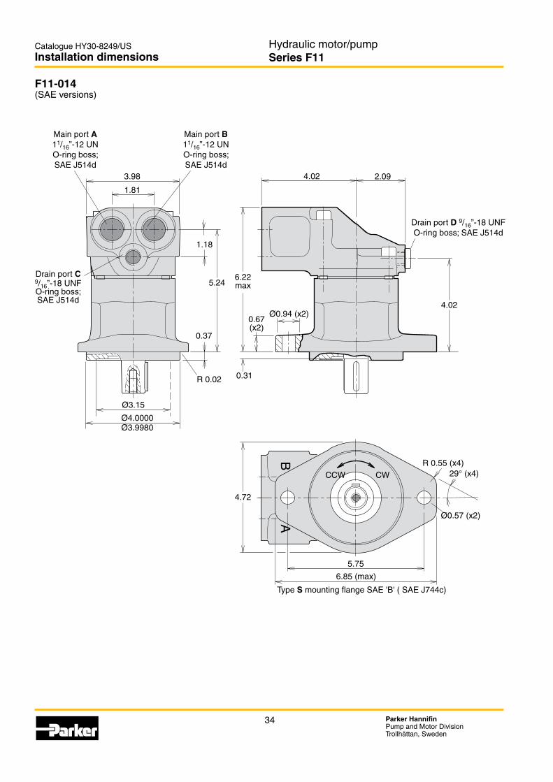
34 Parker HannifinPump and Motor DivisionTrollhättan, Sweden
Hydraulic motor/pumpSeries F11
Catalogue HY30-8249/US
F11-014
Installation dimensions
3.98
1.81
1.18
Ø3.15
Ø0.94 (x2)
Ø0.57 (x2)
4.02
0.31
0.67(x2)
6.22max
5.75
29° (x4)
4.02 2.09
4.72
6.85 (max)
BA
R 0.55 (x4)
R 0.02
5.24
0.37
Ø4.0000Ø3.9980
CCW CW
Drain port D 9/16”-18 UNF
Type S
Drain port C 9/16”-18 UNFO-ring boss;
Main port A 11/16”-12 UNO-ring boss;
Main port B 11/16”-12 UNO-ring boss;

35 Parker HannifinPump and Motor DivisionTrollhättan, Sweden
Hydraulic motor/pumpSeries F11
Catalogue HY30-8249/US
2
F11-014
Installation dimensions
Ø80
6.22max
25°
BA
5/8 UNF-2A
2.83
(1.26)
(2.28)
1.69
0.25
1.0
0.13
0.912.03
0.08Ø0.16
Ø1.06
1.11
Ø1.0000Ø0.9980
Key ¼"x¼"x1¼"0.09
0.31
0.31
0.94
1.30
5/16"-24 UNF-2B(depth 0.63)
5.94
1.77
4.02
1.50
CCW CW
Speed sensor(optional)
Type T key shaftSize 25-1 (B–B)
Type S spline shaft
30° involute spline;flat root, side fit)
Shaft options
Make up/Anti cavitation valve (MUVL or MUVR optional; clockwise rotation shown)
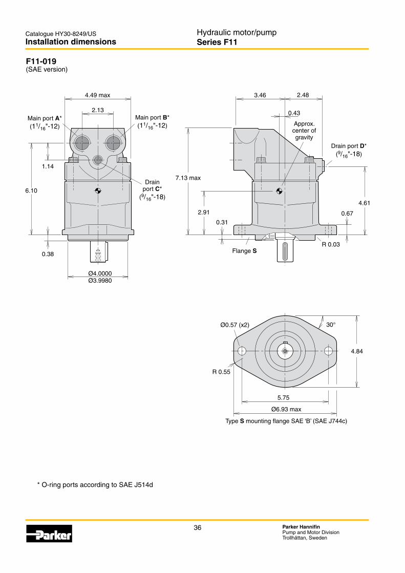
Tapered key shaft "V"
36 Parker HannifinPump and Motor DivisionTrollhättan, Sweden
Hydraulic motor/pumpSeries F11
Catalogue HY30-8249/US
F11-019
Installation dimensions
3.46
0.43
2.48
2.91
0.31
7.13 max
4.61
0.67
2.13
Ø6.93 max
1.14
6.10
30°
R 0.55
4.84
5.75
4.49 max
Ø0.57 (x2)
R 0.03
Ø4.0000Ø3.9980
0.38
Type S
Approx. center of gravity
Flange S
Main port A*(11/16"-12)
Drain port D*(9/16"-18)
Drain port C*
(9/16"-18)
Main port B*(11/16"-12)

37 Parker HannifinPump and Motor DivisionTrollhättan, Sweden
Hydraulic motor/pumpSeries F11
Catalogue HY30-8249/US
2
F11-019
Installation dimensions
3.27
4.33
1.30
1.93
(25°)
7.13 max
6.57
5/16"-24 UNF-2b(depth 0.63)
5/8 UNF-2A
2.40
2.56
ccw cw
1.69
0.25
1.0
0.13
0.912.03
0.08Ø0.16
0.31
0.31
0.09
Key ¼"x¼"x1¼"
1.50
Ø1.0000Ø0.9980
1.11
Ø1.11
1.30
R 0.04
Type T key shaft
Shaft options
Make up/Anti cavitation valve (MUVL or MUVR optional; clockwise rotation shown)
Type S spline shaft
30° involute spline;flat root, side fit)
Speed sensor(optional)
Tapered key shaft "V"

38 Parker HannifinPump and Motor DivisionTrollhättan, Sweden
Hydraulic motor/pumpSeries F12
Catalogue HY30-8249/US
F12
Content
Content PageF12 cross sections ........................................................................................39Specifications ...............................................................................................40
......................................................................................................41Noise level ....................................................................................................41Selfpriming speed and required inlet pressure .............................................42Ordering codesF12-ISO ........................................................................................................43F12-Cartridge ...............................................................................................44
.......................................................................................................45Installation dimensionsF12-030, -040, -060, -080, -090, -110 and -125 ISO ...................................46F12-030, -040, -060, -080, -090, -110 and -125 Cartridge ...........................48
..............50 ..................................................52
F12-150 Cetop ..............................................................................................54 ................................................................................................55 ................................................................................................56
...................................................................................57

39 Parker HannifinPump and Motor DivisionTrollhättan, Sweden
Hydraulic motor/pumpSeries F12
Catalogue HY30-8249/US
3
F12_60_section.epsLeif A./020204
1 2 3 4 5 6 7 8 9
F12_110_section.epsLeif A./020204
1 2 3 10 4 5 6 7 8 9
11
F12 cross sections
1. Barrel housing 2. Valve plate 3. Cylinder barrel 4. Piston with piston ring
F12-030, -040, -060, -080 and -090(F12-060 shown)
5. Timing gear 6. Tapered roller bearings 7. Bearing housing 8. Shaft seal
9. Output/input shaft
11. Needle bearings (F12-110 and -125)
F12-110 and -125(F12-110 shown)
Legend:
General information

40 Parker HannifinPump and Motor DivisionTrollhättan, Sweden
Hydraulic motor/pumpSeries F12
Catalogue HY30-8249/USSpecifications
Frame size F12 -030 -040 -060 -080 -090 -110 -125 -150 -250Displacement [cm3/rev] 30.0 40.0 59.8 80.4 93.0 110.1 125.0 150 242
[cu in/rev] 1.83 2.44 3.65 4.91 5.68 6.72 7.63 9.15 14.8Operating pressure
max intermittent1) [bar] 480 480 480 480 420 480 480 420 420[psi] 7 000 7 000 7 000 7 000 6 000 7 000 7 000 6000 6000
max continuous [bar] 420 420 420 420 350 420 420 350 350[psi] 6000 6000 6000 6000 5 000 6000 6000 5000 5000
Motor operating speed [rpm]max intermittent 1) 7 300 6 700 5 800 5 300 5 000 4 800 4 600 3 500 3 000max continuous 3) 6 700 6 100 5 300 4 800 4 600 4 400 4 200 3 200 2 700
min continuous 50 50 50 50 50 50 50 50 50Max pump selfpriming speed 2)
L or R function; max [rpm] 3150 2870 2500 2300 2 250 2200 2 100 1 700 1 500Motor input flow
max intermittent1) [l/min] 219 268 347 426 465 528 575 525 726[gpm] 57.9 70.8 91.7 112.5 122.8 139.5 151.9 138.7 191.8
max continuous [l/min] 201 244 317 386 428 484 525 480 653[gpm] 53.1 64.5 83.7 102.0 113.1 127.9 138.7 126.8 172.5
Drain temperature3), max [°C] 115 115 115 115 115 115 115 115 115[° F] 239 239 239 239 239 239 239 239 239
min [°C] -40 -40 -40 -40 -40 -40 -40 -40 -40[° F] -40 -40 -40 -40 -40 -40 -40 -40 -40
Theoretical torque at 100 bar [Nm] 47.6 63.5 94.9 127.6 147.6 174.8 198.4 238.1 384.1[lbf ft] 35.1 46.9 70.0 94.2 108.9 129.0 146.4 175.7 283.5
Mass moment of inertia (x10-3) [kg m2] 1.7 2.9 5 8.4 8.4 11.2 11.2 40 46(x10-2) [lbft2] 4.03 6.88 11.86 19.93 19.93 26.58 26.58 94.92 109.16Weight [kg] 12 16.5 21 26 26 36 36 70 77
[lb] 26 36 46 57 57 79 79 154 170
1) Intermittent: max 6 seconds in any one minute. 2) Selfpriming speed valid at sea level. Find more info on page 42 3) See also installation information. Page 67
41 Parker HannifinPump and Motor DivisionTrollhättan, Sweden
Hydraulic motor/pumpSeries F12
Catalogue HY30-8249/US
3
Noise level[dB(A)]
90
85
80
75
70
65
0 1000 2000 3000 4000 5000 Pressure [psi]
Noise_F12_US_PC.epsLeif A./02-10-14
5000 rpm
3500 rpm
2000 rpm
Efficiency_F12_US_PC.epsLeif A./02-10-14
100%
90%
80%
0 1000 2000 3000 4000 Speed [rpm]
100%
90%
80%
0 1000 2000 3000 4000 Speed [rpm]
3000 psi
6000 psi
6000 psi
3000 psi
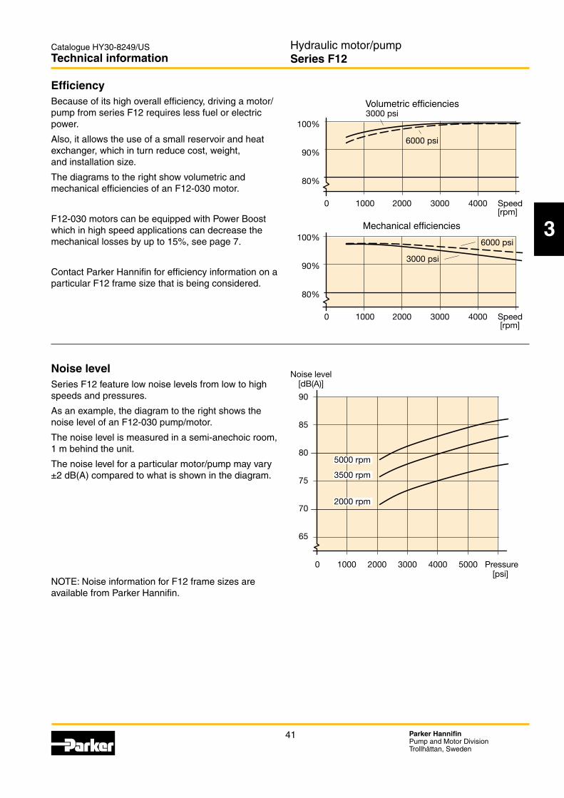
EfficiencyBecause of its high overall efficiency, driving a motor/ pump from series F12 requires less fuel or electric power.
Also, it allows the use of a small reservoir and heat exchanger, which in turn reduce cost, weight, and installation size.
The diagrams to the right show volumetric and mechanical efficiencies of an F12-030 motor.
F12-030 motors can be equipped with Power Boost which in high speed applications can decrease the mechanical losses by up to 15%, see page 7.
Contact Parker Hannifin for efficiency information on a particular F12 frame size that is being considered.
Noise levelSeries F12 feature low noise levels from low to high speeds and pressures.
As an example, the diagram to the right shows the noise level of an F12-030 pump/motor.
The noise level is measured in a semi-anechoic room, 1 m behind the unit.
The noise level for a particular motor/pump may vary ±2 dB(A) compared to what is shown in the diagram.
available from Parker Hannifin.
Technical information
Mechanical efficiencies
Volumetric efficiencies

42 Parker HannifinPump and Motor DivisionTrollhättan, Sweden
Hydraulic motor/pumpSeries F12
Catalogue HY30-8249/US
1000 2000 3000 4000 5000
F12-250-150-125 -110 -90 -80 -60 -40 -3029
25
20
15
10
5
0
-5
Inlet pressure [psi]
Speed [rpm]
Inlet pressure [psi]
Speed [rpm]
Selfpriming speed and required inlet pressureSeries F12When operating the F12 as a pump (with L or R valve plate) above the selfpriming speed, the inlet must be pressurized. Increased noise and deteriorating perform-ance may otherwise be experienced.Diagrams 2 and 3 shows required pump inlet pressure vs. shaft speed.The F12 motor (type M valve plate) sometimes operates as a pump e.g. when used in a propel transmission and the vehicle is going downhill.Minimum required inlet pressure versus shaft speed is shown in the diagrams.The inlet pressure can be charged by external pump, pressurized reservoir or using BLA Boost unit.Find more info about the BLA unit at page 66.
Diagram 2. Min. required pump (F12-L or -R) inlet press.
Diagram 3. Min. required motor (F12-M) inlet pressure.
Technical information
1000 2000 3000 4000
F12-250-150-125 -110 -90 -80 -60 -40 -3029
25
20
15
10
5
0
-5
F12 Motor
F12 Pump
2.18 psi vacuum
2.18 psi vacuum

43 Parker HannifinPump and Motor DivisionTrollhättan, Sweden
Hydraulic motor/pumpSeries F12
Catalogue HY30-8249/US
3
Ordering codes
F12-ISO
F12 — — —— — — —
Framesize
Function Main
ports
Mounting
flange
Shaft
seal
Shaft Version
number
Option
page 6, 61
Option
page 7, 65
Version number(assigned for special
versions)
Frame sizeCode Displacem.
(cm3/rev)Displacem. (cu in/rev)
030 30.0 1.83040 40.0 2.44060 59.8 3.65080 80.4 4.91090 93.0 5.68110 110.1 6.72125 125.0 7.63
x : Available (x): Optional – : Not available1) F12-110 and -125: Accessory valve block (page 60)2) Pressure setting on page 61
Frame size 30 40 60 80 90 110 125Code Function
M Motor x x x x x x xS Motor, high speed (x) (x) (x) - - - -R Pump, clockwise
rotation(x) (x) (x) (x) (x) (x) (x)
L Pump, counter (x) (x) (x) (x) (x) (x) (x)
For other versions, contact Parker Hannifin
Frame size 30 40 60 80 90 110 125Code Option0000 Standard x x x x x x xL130 Flushing valve 1.3 mm orifice (x) (x) (x) (x) (x) -1) -1)
MUVR Make up/Anti cavitation valve clockwise rotation
(x) - - - - - -
MUVL Make up/Anti cavitation valve counter clockwise rotation
(x) - - - - - -
P__R 2)
Pressure relief valve clockwise rotation
(x) (x) (x) - - - -
P__L 2)
Pressure relief valve counter clockwise rotation
(x) (x) (x) - - - -
Frame size 30 40 60 80 90 110 125Code Shaft*
D DIN Spline, Standard x x x x x x xA DIN Spline, Optional - (x) - - - - -Z DIN Spline, Optional (x) (x) (x) (x) (x) (x) (x)K Metric key, Standard x x x x x x xJ Metric key, Optional - (x) - - - - -P Metric key, Optional (x) - - - - - -V Tapered shaft (x) (x) (x) - - (x) (x)
*See also dimensional drawings on page 46.
Frame size 30 40 60 80 90 110 125Code Shaft seal
N NBR, low pressure (x) (x) (x) (x) (x) (x) (x)V FPM, high pressure,
high temperaturex x x x x x x
S (x) - - - - - -
Frame size 30 40 60 80 90 110 125Code Main ports
F x x x x x x x
Frame size 30 40 60 80 90 110 125Code Mounting flange
I ISO flange x x x x x x x
Frame size 30 40 60 80 90 110 125Code Option
00 Standard x x x x x x xP_ Prepared for speed sensor (x) (x) (x) (x) (x) (x) (x)
B_ Power Boost and Prepared for speed sensor
(x) - - - - - -
_T Painted Black (x) (x) (x) (x) (x) (x) (x)

44 Parker HannifinPump and Motor DivisionTrollhättan, Sweden
Hydraulic motor/pumpSeries F12
Catalogue HY30-8249/US
F12-Cartridge CETOP
Ordering codes
F12 — — —— — — —
Framesize
Function Main
ports
Mounting
flange
Shaft
seal
Shaft Version
number
Option
page 6, 61
Option
page 7, 65
Version number(assigned for special
versions)
Frame sizeCode Displacem.
(cm3/rev)Displacem. (cu in/rev)
030 30.0 1.83040 40.0 2.44060 59.8 3.65080 80.4 4.91090 93.0 5.68110 110.1 6.72125 125.0 7.63150 150.0 9.15
x : Available (x): Optional – : Not available1) F12-110 and -125: Accessory valve block (page 60)2) Pressure setting on page 61
Frame size 30 40 60 80 90 110 125 150Code Function
M Motor x x x x x x x xS Motor, high
speed(x) (x) (x) - - - - -
R Pump, clockwise rotation
- - - - - - - (x)
L Pump, counter - - - - - - - (x)
For other versions, contact Parker Hannifin
Frame size 30 40 60 80 90 110 125 150Code Shaft*
C DIN Spline, Std. x x x x x x x -K Metric key, Option (x) - (x) (x) (x) (x) (x) xJ Metric key, Option - (x) - - - - - -B Spline DIN 5480 - - (x) - - (x) (x) -D Spline DIN 5480 - - - - - - - (x)V Tapered shaft (x) (x) (x) - - (x) (x) -
*See also dimensional drawings on pages 48 and 54.
Frame size 30 40 60 80 90 110 125 150Code Shaft seal
N NBR, low pressure (x) (x) (x) (x) (x) (x) (x) (x)V FPM, high pressure,
high temperaturex x x x x x x x
S (x) - - - - - - -
Frame size 30 40 60 80 90 110 125 150Code Main ports
F x x x x x x x x
Frame size 30 40 60 80 90 110 125 150Code Mounting flange
C Cartridge x x x x x x x -C - - - - - - - x
Frame size 30 40 60 80 90 110 125150Code Option0000 Standard x x x x x x x xL130 Flushing valve 1.3 mm
orifice(x) (x) (x) (x) (x) -1) -1) -
MUVR Make up/Anti cavitation valve clockwise rotation
(x) - - - - - - -
MUVL Make up/Anti cavitation valve counter clockwise rotation
(x) - - - - - - -
P__R 2)
Pressure relief valve clockwise rotation
(x) (x) (x) - - - - -
P__L 2)
Pressure relief valve coun-ter clockwise rotation
(x) (x) (x) - - - - -
Frame size 30 40 60 80 90 110 125 150Code Option
00 Standard x x x x x x x xP_ Prepared for speed sensor x (x) (x) (x) (x) x x -
B_ Power Boost and Prepared for speed sensor
(x) - - - - - - -
_T Painted Black (x) (x) (x) (x) (x) (x) (x) (x)

45 Parker HannifinPump and Motor DivisionTrollhättan, Sweden
Hydraulic motor/pumpSeries F12
Catalogue HY30-8249/US
3
Ordering codes
F12 — — —— — — —
F12-SAE Frame
size
Function Main
ports
Mounting
flange
Shaft
seal
Shaft Version
number
Option
page 6, 61
Option
page 7, 65
Version number(assigned for special
versions)
Frame sizeCode Displacem.
(cm3/rev)Displacem. (cu in/rev)
030 30.0 1.83040 40.0 2.44060 59.8 3.65080 80.4 4.91090 93.0 5.68110 110.1 6.72125 125.0 7.63150 150.0 9.15250 242.0 14.8
x : Available (x): Optional – : Not available1) F12-110 and -125: Accessory valve block (page 60)2) Metric threads3) Pressure setting on page 61
Frame size 30 40 60 80 90 110 125 150 250Code Function
M Motor x x x x x x x x -S Motor, high
speed(x) (x) (x) - - - - - -
Q Motor - - - - - - - - xR Pump, clockwise
rotation(x) (x) (x) (x) (x) (x) (x) (x) (x)
L Pump, counter (x) (x) (x) (x) (x) (x) (x) (x) (x)
For other versions, contact Parker Hannifin
Frame size 30 40 60 80 90 110 125 150 250Code Option0000 Standard x x x x x x x x xL130 Flushing valve 1.3 mm
orifice(x) (x) (x) (x) (x) -1) -1) - -
MUVR Make up/Anti cavitation valve clockwise rotation
(x) - - - - - - - -
MUVL Make up/Anti cavitation valve counter clockwise rotation
(x) - - - - - - - -
P__R 3)
Pressure relief valve clockwise rotation
(x) (x) (x) - - - - - -
P__L 3)
Pressure relief valve counter clockwise rotation
(x) (x) (x) - - - - - -
Frame size 30 40 60 80 90 110 125 150 250Code Shaft*
T x x x x x x x x xR - - - (x) (x) - - - -S (x) (x) (x) (x) (x) (x) (x) (x) (x)F - - - (x) (x) - - (x) (x)U - - - (x) (x) - - - -K Metric key, Standard - - - - - - - (x) xD Spline DIN 5480 - - - - - - - - (x)V Tapered shaft (x) (x) (x) - - (x) (x) - -
*See also dimensional drawings on pages 50 - 53, 55 - 57.
Frame size 30 40 60 80 90 110 125 150 250Code Shaft seal
N NBR, low pressure (x) (x) (x) (x) (x) (x) (x) (x) -V FPM, high pressure,
high temperaturex x x x x x x x x
S (x) - - - - - - - -
Frame size 30 40 60 80 90 110 125 150 250Code Main ports
S x x x x x x x - -U (x) (x) (x) (x) (x) (x) (x) - -F 2) - - - - - - - x x
Frame size 30 40 60 80 90 110 125 150 250Code Mounting flange
S x x x x x x x x xT x x x - - - - - -R - - - (x) (x) - - - -
Frame size 30 40 60 80 90 110 125 150250Code Option
00 Standard x x x x x x x x xP_ Prepared for speed sensor (x) (x) (x) (x) (x) x x - (x)
B_ Power Boost and Prepared for speed sensor
(x) - - - - - - -
_T Painted Black (x) (x) (x) (x) (x) (x) (x) (x) (x)

46 Parker HannifinPump and Motor DivisionTrollhättan, Sweden
Hydraulic motor/pumpSeries F12
Catalogue HY30-8249/US
A1
A1
A3
B3
K3
L3
C3A2
G2
J2
N2G3
H3
J3
F3
D3
ØE3 (Tol. k6)
P2
L2
M2D2
ØE2
ØF2 (tol. h8)
H2(±0.02)
K2
B2
C2
ØD1 (x4)B1
C1
T3
ccw cw
R2
Q2S22)
27.95 38.19
15.62
1 1/4˝-12 UNF-2A
24.41 33.66
13.75
R0.79
1 1/8˝-12 UNF
Ø1.57
Ø12.50Ø15.00
Ø17.50
Ø1.57Ø1.57
19.2925.94
12.19
Key 3.13x3.13x10.20Key 3.76x3.76x17.50
Key 4.37x4.37x20.00
1˝-12 UNF-2A
F12-30, -40, -60, -80, -90, -110 and -125(ISO versions)
Installation dimensions
Type I mounting flange (ISO 3019/2)
Port E (third drain port)F12-110 and -125 barrel housing
(ISO /cartridge version)
Port BPort A
Port D
Type K (P)Key shaft
2) Type Z has no thread
Port C1)
F12-80 shown
Speed sensor
(optional)
Type I flange
See table
Flushing valve
(optional)
Type D (Z) spline shaft
1) Port C Inspection/ drain port
Shaft option D (Z)
Tapered key shaft "V" Tapered key shaft "V"
Tapered key shaft "V"
Shaft option V (F12-30) Shaft option V (F12-40) Shaft option V (F12-60)

47 Parker HannifinPump and Motor DivisionTrollhättan, Sweden
Hydraulic motor/pumpSeries F12
Catalogue HY30-8249/US
3
Spline shaft (DIN 5480)
Metric key shaft (in mm)
Installation dimensions
Type K (std)
Type P (opt.)
Type J (opt.)
Type V (opt.)
F12-30 Ø30 Ø253) - 32-3
-40 Ø30 - Ø35 38-3
-60 Ø35 - - 44-3
-80 Ø40 - - -
-90 Ø40 - - -
-110 Ø45 - - 44-3
-125 Ø45 - - 44-3
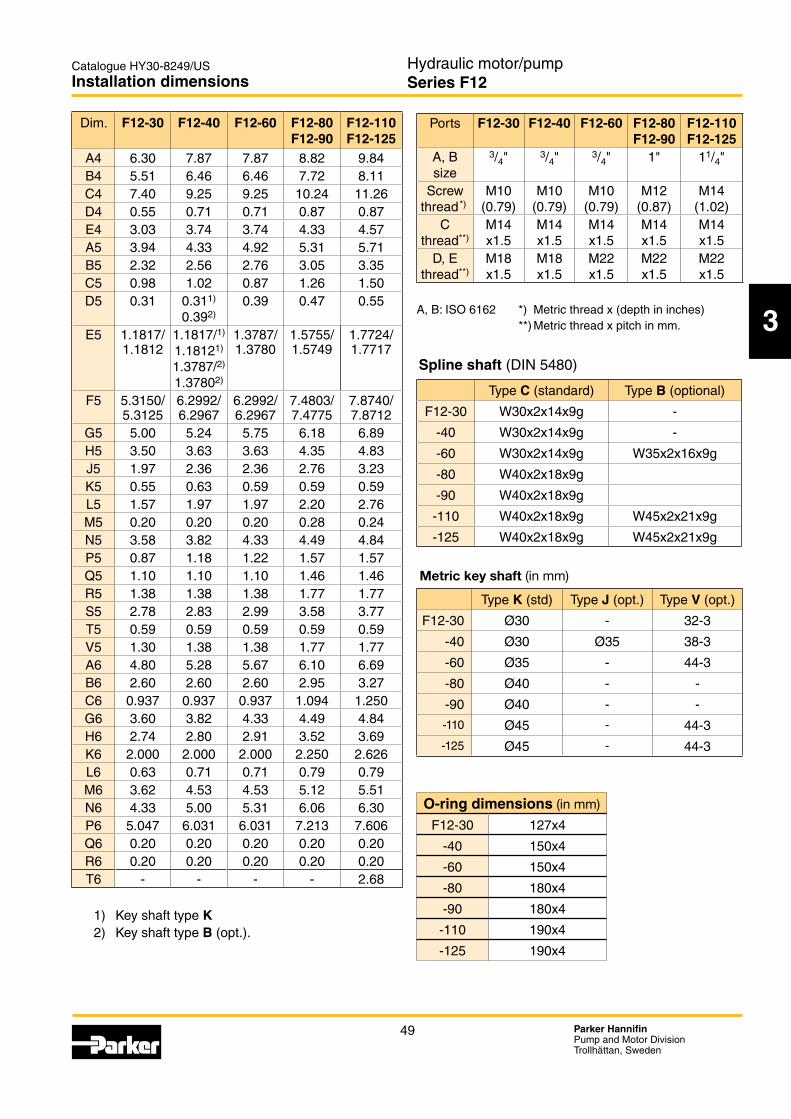
Dim. F12-30 F12-40 F12-60 F12-80 F12-90
F12-110 F12-125
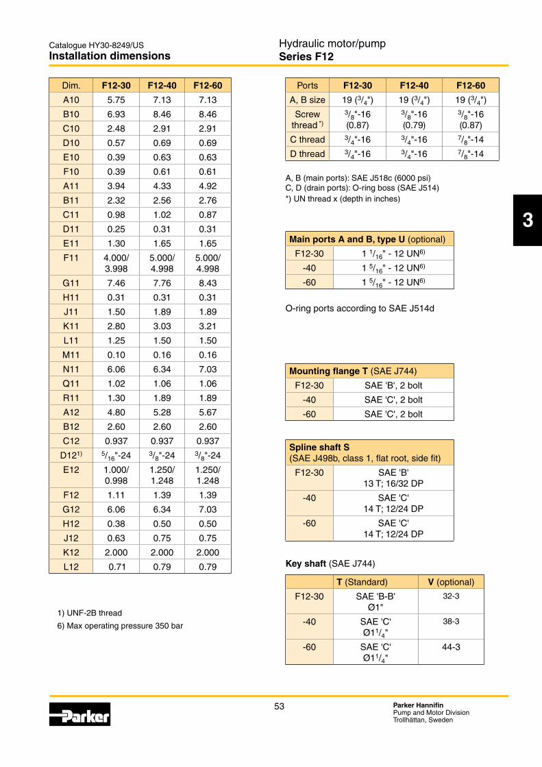
A1 3.48 4.46 4.46 5.01 5.57B1 4.65 5.75 5.75 6.22 7.09C1 4.65 5.59 5.67 6.10 7.09D1 0.43 0.53 0.53 0.53 0.71A2 3.94 4.33 4.92 5.32 5.71B2 2.32 2.56 2.76 3.05 3.35C2 0.98 1.02 0.87 1.26 1.50D2 0.32 0.32 0.39 0.47 0.55
1.30 1.65 1.65 2.05 2.26F2 3.9370/
3.93494.9213/ 4.9188
4.9213/ 4.9188
5.5118/ 5.5093
6.2992/ 6.2967
G2 6.77 6.81 7.48 8.50 9.09H2 1.00 1.28 1.28 1.28 1.59J2 1.97 2.36 2.36 2.76 3.23K2 2.16 2.05 2.13 2.76 2.61L2 1.58 1.97 1.97 2.21 2.76M2 0.20 0.20 0.20 0.28 0.24N2 5.37 5.39 6.06 6.79 7.05P2 0.32 0.32 0.32 0.32 0.32Q2 1.10 1.10 1.30 1.42 1.61
R21) 1.38 1.38 1.57 1.77 1.97R22) 1.69 1.38 - 1.61 -S21)* M12
x0.94M12 x0.94
M12 x1.10
M16 x1.42
M16 x1.42
S22)* - M12 x0.94
- M12 x1.10
-
A3 4.80 5.28 5.67 6.10 6.69B3 2.60 2.60 2.60 2.95 3.29C3 0.937 0.937 0.937 1.094 1.250D3* M12 M12 M12 M16 M16
1.1817/ 1.1812
1.1817/ 1.1812
1.3787/ 1.3780
1.5755/ 1.5749
1.7724/ 1.7717
F3 1.30 1.30 1.50 1.69 1.91G3 5.37 5.39 6.06 6.79 7.05H3 0.93 1.20 1.20 1.20 1.52J3 0.95 0.95 1.10 1.42 1.42K3 2.000 2.000 2.000 2.250 2.626L3 0.71 0.79 0.79 0.79 0.87T3 - - - - 2.68
* Metric thread (x depth in inches)1) Spline shaft type D2) Spline shaft type Z3) Max operating pressure 5100 psi 350 bar
Ports F12-30 F12-40 F12-60 F12-80 F12-90
F12-110 F12-125
A, B size
3/4" 3/4" 3/4" 1" 11/4"
Screw thread*)
M10 (0.79)
M10 (0.79)
M10 (0.79)
M12 (0.79)
M14 (1.02)
C thread**)
M22 x1.5
M22 x1.5
M22 x1.5
M22 x1.5
M22 x1.5
D thread**)
M18 x1.5
M18 x1.5
M22 x1.5
M22 x1.5
M22 x1.5
thread**)
- - - - M22 x1.5
A, B: ISO 6162 *) Metric thread x (depth in inches) **) Metric thread x pitch in mm.
Type D (std) Type A Type Z (optional)
F12-30 W30x2x14x9g - W25x1.25x18x9g3)
-40 W32x2x14x9g W35x2x16x9g W30x2x14x9g
-60 W35x2x16x9g - W32x2x14x9g
-80 W40x2x18x9g - W35x2x16x9g3)
-90 W40x2x18x9g - W35x2x16x9g3)
-110 W45x2x21x9g - W40x2x18x9g3)
-125 W45x2x21x9g - W40x2x18x9g3)

48 Parker HannifinPump and Motor DivisionTrollhättan, Sweden
Hydraulic motor/pumpSeries F12
Catalogue HY30-8249/US
A4
B4
A5
G5
R5 Q5 ØV5
ØF5 (Tol. h8)
H5(±0.02)
K5
S5
T5
B5
C5
N5G6
H6
ØM6ØN6ØP6
Q6L6
A6
B6C6
K6
R6
P5
C4
T6
E4
ØD4(x2)
40° (-30, -40, -60, -110, -125)43° (-80, -90)
ccw cw
ØE5 (Tol. k6)
J5
D5
L5
M5
1 1/4˝-12 UNF-2A1 1/8˝-12 UNF
1˝-12 UNF-2AØ1.57
Ø12.50
19.2925.94
12.19
Key 3.13x3.13x10.20
24.41 33.66
13.75
R0.79
Ø15.00
Ø1.57
Key 3.76x3.76x17.50
27.95 38.19
15.62
Ø17.50
Ø1.57
Key 4.37x4.37x20.00
F12-30, -40, -60, -80, -90, -110 and -125 (Cartridge versions)
Installation dimensions
F12-80 shown
Type C mounting flangePort E (third drain port)
F12-110 and -125 barrel housing(ISO /cartridge version)
Port A Port B
Speed sensor
(optional)
Port C1)
Type C spline shaft
See table
Type K (J) key shaft
O-ring (included)
Flushing valve
(optional)
Port D
1) Port C Inspection/ drain port
Tapered key shaft "V" Tapered key shaft "V"
Tapered key shaft "V"
Shaft option K (J) Shaft option V (F12-30) Shaft option V (F12-40) Shaft option V (F12-60)
49 Parker HannifinPump and Motor DivisionTrollhättan, Sweden
Hydraulic motor/pumpSeries F12
Catalogue HY30-8249/US
3
Type K (std) Type J (opt.) Type V (opt.)
F12-30 Ø30 - 32-3
-40 Ø30 Ø35 38-3
-60 Ø35 - 44-3
-80 Ø40 - -
-90 Ø40 - --110 Ø45 - 44-3-125 Ø45 - 44-3
Spline shaft (DIN 5480)
Metric key shaft (in mm)
Installation dimensions
Dim. F12-30 F12-40 F12-60 F12-80 F12-90
F12-110 F12-125
A4 6.30 7.87 7.87 8.82 9.84B4 5.51 6.46 6.46 7.72 8.11C4 7.40 9.25 9.25 10.24 11.26D4 0.55 0.71 0.71 0.87 0.87
3.03 3.74 3.74 4.33 4.57A5 3.94 4.33 4.92 5.31 5.71B5 2.32 2.56 2.76 3.05 3.35C5 0.98 1.02 0.87 1.26 1.50D5 0.31 0.311)
0.392)0.39 0.47 0.55
1.1817/ 1.1812
1.1817/1) 1.18121)
1.3787/2) 1.37802)
1.3787/ 1.3780
1.5755/ 1.5749
1.7724/ 1.7717
F5 5.3150/ 5.3125
6.2992/ 6.2967
6.2992/ 6.2967
7.4803/ 7.4775
7.8740/ 7.8712
G5 5.00 5.24 5.75 6.18 6.89H5 3.50 3.63 3.63 4.35 4.83J5 1.97 2.36 2.36 2.76 3.23K5 0.55 0.63 0.59 0.59 0.59L5 1.57 1.97 1.97 2.20 2.76M5 0.20 0.20 0.20 0.28 0.24N5 3.58 3.82 4.33 4.49 4.84P5 0.87 1.18 1.22 1.57 1.57Q5 1.10 1.10 1.10 1.46 1.46R5 1.38 1.38 1.38 1.77 1.77S5 2.78 2.83 2.99 3.58 3.77T5 0.59 0.59 0.59 0.59 0.59V5 1.30 1.38 1.38 1.77 1.77A6 4.80 5.28 5.67 6.10 6.69B6 2.60 2.60 2.60 2.95 3.27C6 0.937 0.937 0.937 1.094 1.250G6 3.60 3.82 4.33 4.49 4.84H6 2.74 2.80 2.91 3.52 3.69K6 2.000 2.000 2.000 2.250 2.626L6 0.63 0.71 0.71 0.79 0.79M6 3.62 4.53 4.53 5.12 5.51N6 4.33 5.00 5.31 6.06 6.30P6 5.047 6.031 6.031 7.213 7.606Q6 0.20 0.20 0.20 0.20 0.20R6 0.20 0.20 0.20 0.20 0.20T6 - - - - 2.68
1) Key shaft type K 2) Key shaft type B (opt.).
Ports F12-30 F12-40 F12-60 F12-80 F12-90
F12-110 F12-125
A, B size
3/4" 3/4" 3/4" 1" 11/4"
Screw thread*)
M10 (0.79)
M10 (0.79)
M10 (0.79)
M12 (0.87)
M14 (1.02)
C thread**)
M14 x1.5
M14 x1.5
M14 x1.5
M14 x1.5
M14 x1.5
thread**)
M18 x1.5
M18 x1.5
M22 x1.5
M22 x1.5
M22 x1.5
A, B: ISO 6162 *) Metric thread x (depth in inches) **) Metric thread x pitch in mm.
Type C (standard) Type B (optional)
F12-30 W30x2x14x9g -
-40 W30x2x14x9g -
-60 W30x2x14x9g W35x2x16x9g
-80 W40x2x18x9g
-90 W40x2x18x9g
-110 W40x2x18x9g W45x2x21x9g
-125 W40x2x18x9g W45x2x21x9g
O-ring dimensions (in mm)
F12-30 127x4
-40 150x4
-60 150x4
-80 180x4
-90 180x4
-110 190x4
-125 190x4

50 Parker HannifinPump and Motor DivisionTrollhättan, Sweden
Hydraulic motor/pumpSeries F12
Catalogue HY30-8249/US
A7
A7 ØD7 (x4)
B7
C7
T9
A8
G8
J8
N8
L8
M8D8
ØE8
ØF8
H8
K8
B8
C8
A9B9
K9
L9
C9
G9
H9J9
F9
D9 ØE9
ccw cw
R8
Q8
1 1/4˝-12 UNF-2A1 1/8˝-12 UNF
1˝-12 UNF-2A
27.95 38.19
15.62
24.41 33.66
13.75
R0.79
Ø1.57
Ø12.50Ø15.00
Ø17.50
Ø1.57Ø1.57
19.29 25.94
12.19
Key 3.13x3.13x10.20Key 3.76x3.76x17.50
Key 4.37x4.37x20.00
F12-30, -40, -60, -80, -90, -110 and -125
Installation dimensions
Shown: F12-80 with 4 bolt flange
Type Smounting flange Port E (third drain port)
F12-110 and -125 barrel housing
Port A Port B
Port C1)
Speed sensor
(optional)
Type S flange
See
table
Type S (U) spline shaft
Type T key shaft
Flushing valve
(optional)
Port D
1) Port C Inspection/ drain port
Shaft option S (U)
Tapered key shaft "V" Tapered key shaft "V"
Tapered key shaft "V"
Shaft option V (F12-30) Shaft option V (F12-40) Shaft option V (F12-60)

51 Parker HannifinPump and Motor DivisionTrollhättan, Sweden
Hydraulic motor/pumpSeries F12
Catalogue HY30-8249/US
3Mounting flange
Installation dimensions
Dim. F12-30 F12-40 F12-60 F12-80 F12-90
F12-110 F12-125
A7 3.54 4.51 4.51 4.51 6.36B7 4.65 5.83 5.83 6.10 8.03C7 4.65 5.67 5.67 6.10 7.87D7 0.55 0.55 0.55 0.55 0.83A8 3.94 4.33 4.92 5.31 5.71B8 2.32 2.56 2.76 3.05 3.35C8 0.98 1.02 0.87 1.26 1.50D8 0.25 0.31 0.31 0.38 0.44
1.30 1.65 1.65 2.05 2.26F8 4.000/
3.9985.000/ 4.998
5.000/ 4.998
5.000/ 4.998
6.000/ 5.998
G8 7.46 7.76 8.43 9.45 10.39H8 0.31 0.31 0.31 0.31 0.31J8 1.50 1.89 1.89 2.13 2.64K8 2.83 2.99 3.11 3.74 3.90L8 1.25 1.50 1.50 1.75 2.13M8 0.10 0.16 0.16 0.16 0.29N8 6.04 6.34 7.02 7.76 8.35
Q81) 0.91 0.91 0.91 0.98 1.34Q82) - - - 0.91 -R81) 1.30 1.89 1.89 2.13 2.63R82) - - - 1.88 -A9 4.80 5.28 5.67 6.10 6.69B9 2.60 2.60 2.60 2.95 3.27C9 0.937 0.937 0.937 1.094 1.250D9* 5/16"-24 3/8"-24 3/8"-24 1/2"-20 5/8"-18
1.000/ 0.998
1.250/ 1.248
1.250/ 1.248
1.500/ 1.498
1.750/ 1.748
F9 1.11 1.39 1.39 1.67 1.94G9 6.06 6.34 7.02 7.76 8.35H9 0.38 0.50 0.50 0.50 0.50J9 0.63 0.75 0.75 1.02 1.26K9 2.000 2.000 2.000 2.250 2.626L9 0.71 0.79 0.79 0.79 0.87T9 - - - - 2.68
* UNF-2B thread1) Spline shaft type S2) Spline shaft type U3) Max operating pressure 350 bar
Main ports A and B, type U (optional)
F12-30 1 1/16" - 12 UN3)
F12-40 1 5/16" - 12 UN3)
F12-60 1 5/16" - 12 UN3)
F12-80 1 5/16" - 12 UN3)
F12-90 1 5/16" - 12 UN3)
F12-110 1 5/8" - 12 UN3)
F12-125 1 5/8" - 12 UN3)
Ports F12-30
F12-40
F12-60
F12-80 F12-90
F12-110 F12-125
A, B size 3/4" 3/4" 3/4" 1" 11/4"Screw
thread**)
3/8"-16 (0.87)
3/8"-16 (0.79)
3/8"-16 (0.87)
7/16"-14 (1.06)
1/2"-13 (0.98)
C thread 7/8"-14 7/8"-14 7/8"-14 7/8"-14 11/16"-12D thread 3/4"-16 3/4"-16 7/8"-14 7/8"-14 11/16"-12
- - - - 11/16"-12
**) UN thread x (depth in inches)
S (standard) R (optional) F12-30 -
-40 --60 --80-90-110 --125 -
Spline shaft
S (standard) U (opt.) F (optional)F12-30
13T, 16/32 DP- -
-4012/24 DP
- -
-6012/24 DP
- -
-80 17T, 12/24 DP
14T,12/24DP3)
13T, 8/16 DP
-90 17T, 12/24 DP
14T,12/24DP3)
13T, 8/16 DP
-110 13T, 8/16 DP
- -
-125 13T, 8/16 DP
- -
Key shaft
F12 T (standard) R (optional) V (optional)-30
(Ø1")- 32-3
-40 (Ø11/4")
- 38-3
-60 (Ø11/4")
- 44-3
-80 (Ø11/2")
(Ø13/4")
-
-90 (Ø11/2")
(Ø13/4")
-
-110 (Ø13/4")
- 44-3
-125 (Ø13/4")
- 44-3

52 Parker HannifinPump and Motor DivisionTrollhättan, Sweden
Hydraulic motor/pumpSeries F12
Catalogue HY30-8249/US
ØD10(x2)
A10
B10
G11
J11 D11
A11 B11
C11
N11
L12
A12
B12C12
G12
H12
K12
J12
F12
D12ØE12
L11
M11ØE11ØF11
K11
H11
F10
E10 RC10 R
ccw cw
R11
Q11
1 1/8˝-12 UNF1˝-12 UNF-2A
1 1/4˝-12 UNF-2A
27.95 38.19
15.62
24.41 33.66
13.75
R0.79
Ø1.57
Ø12.50Ø15.00
Ø17.50
Ø1.57Ø1.57
19.2925.94
12.19
Key 3.13x3.13x10.20
Key 3.76x3.76x17.50Key 4.37x4.37x20.00
F12-30, -40, and -60
Installation dimensions
Port A Port BPort D
Flushing valve
(optional)
Type T key shaftType T
flange
Speed sensor
(optional)
1) Port C Inspection/ drain port
Port C1)
Type T mounting flange
Shown: F12-60 with 2 bolt flange
See
table
Type S spline shaft
Shaft option S
Tapered key shaft "V"
Tapered key shaft "V" Tapered key shaft "V"
Shaft option V (F12-30) Shaft option V (F12-40) Shaft option V (F12-60)
53 Parker HannifinPump and Motor DivisionTrollhättan, Sweden
Hydraulic motor/pumpSeries F12
Catalogue HY30-8249/US
3
Installation dimensions
Dim. F12-30 F12-40 F12-60
A10 5.75 7.13 7.13
B10 6.93 8.46 8.46
C10 2.48 2.91 2.91
D10 0.57 0.69 0.69
0.39 0.63 0.63
F10 0.39 0.61 0.61
A11 3.94 4.33 4.92
B11 2.32 2.56 2.76
C11 0.98 1.02 0.87
D11 0.25 0.31 0.31
1.30 1.65 1.65
F11 4.000/ 3.998
5.000/ 4.998
5.000/ 4.998
G11 7.46 7.76 8.43
H11 0.31 0.31 0.31
J11 1.50 1.89 1.89
K11 2.80 3.03 3.21
L11 1.25 1.50 1.50
M11 0.10 0.16 0.16
N11 6.06 6.34 7.03
Q11 1.02 1.06 1.06
R11 1.30 1.89 1.89
A12 4.80 5.28 5.67
B12 2.60 2.60 2.60
C12 0.937 0.937 0.937
D121) 5/16"-24 3/8"-24 3/8"-24
1.000/ 0.998
1.250/ 1.248
1.250/ 1.248
F12 1.11 1.39 1.39
G12 6.06 6.34 7.03
H12 0.38 0.50 0.50
J12 0.63 0.75 0.75
K12 2.000 2.000 2.000
L12 0.71 0.79 0.79
1) UNF-2B thread
6) Max operating pressure 350 bar
Ports F12-30 F12-40 F12-60
A, B size 19 (3/4") 19 (3/4") 19 (3/4")
Screw thread *)
3/8"-16 (0.87)
3/8"-16 (0.79)
3/8"-16 (0.87)
C thread 3/4"-16 3/4"-16 7/8"-14
D thread 3/4"-16 3/4"-16 7/8"-14
*) UN thread x (depth in inches)
Main ports A and B, type U (optional)
F12-30 1 1/16" - 12 UN6)
-40 1 5/16" - 12 UN6)
-60 1 5/16" - 12 UN6)
Mounting flange T
F12-30
-40
-60
Spline shaft S
F12-30 13 T; 16/32 DP
-40 14 T; 12/24 DP
-60 14 T; 12/24 DP
Key shaft
T (Standard) V (optional)
F12-30 Ø1"
32-3
-40 Ø11/4"
38-3
-60 Ø11/4"
44-3

54 Parker HannifinPump and Motor DivisionTrollhättan, Sweden
Hydraulic motor/pumpSeries F12
Catalogue HY30-8249/US
W45x2x21x9g
ccw cw
Ø1.9692Ø1.9686
8.74 max
3.98
1.44
3.13
3.35
M16 ; 1.18 deep
9.84
1.97
3.23
1.81
1.81
M16(x8)**
M16 ; 1.18 deep
1.97
1.97
4.29 0.98
0.37
1.22
R 0.03
6.26
12.09
6.77 4.65
0.71
Ø2.24 minØ7.8740Ø7.8712
0.24
Ø9.84
Ø0.87(x4)
9.29 max
9.29
Key 14x9x70(0.55x0.35x2.76metric key)
F12-150
Installation dimensions
Approx. center of gravity
Type C mounting flange
Type K key shaft
Type C flange
Type D spline shaft (DIN 5480)
Drain port D(BSP 3/4")
Drain port C
(BSP 3/4")
Main port A*(11/2")
Main port B*(11/2")
*** Metric thread

55 Parker HannifinPump and Motor DivisionTrollhättan, Sweden
Hydraulic motor/pumpSeries F12
Catalogue HY30-8249/US
3
Installation dimensions
F12-150
Approx. center of gravity
Type S mounting flange
Type S flange
Type T key shaft
Type S
Main port A*(11/2")
Main port B*(11/2")
Drain port D(BSP 3/4")
Drain port C
(BSP 3/4")
1.22
M16(x8)**
SAE 'D'; 13T, 8/16 DP;class 1, flat root, side fit
ccw cw
3.35
11.69
8.74 max
3.98
1.44
3.13
R0.03
0.50
Ø1.7500Ø1.7520
5/8-18 UNFdepth 1.18
1.94
6.180.94
8.00
13.98
6.77 4.65
0.71
0.31
0.26
2.63
Ø2.24 min
Ø6.0000Ø6.0020
R0.03
Key 7/16"x7/16"x21/8"
8.43
0.83 (4x)
7.56 6.36
6.36
0.31
2.63
5/8-11 UNCdepth 1.38
R0.16
1.372.63
1.97091.9657Ø2.26
*** Metric thread
Type F spline shaft
15T-8/16 DP; fillet root, side fit

56 Parker HannifinPump and Motor DivisionTrollhättan, Sweden
Hydraulic motor/pumpSeries F12
Catalogue HY30-8249/US
F12-250
Installation dimensions
Approx. center of gravity
Type S mounting flange
Main port A*(11/2")
Main port B*(11/2")
Drain port D(BSP 3/4")
Drain port C
(BSP 3/4")
ccw cw
9.13
3.98
5.55
1.437
3.125
0.50
R 0.03
Ø6.0000Ø5.9980
13.23
M16**1.38 deep(x8)
Ø1.54 (x2)
7.76 4.65
0.94
1.06
7.09
15.55
3.11
0.31
8.50
7.87max
6.36
6.36
7.87 max
Ø0.83(x4)
* ) ** Metric thread

57 Parker HannifinPump and Motor DivisionTrollhättan, Sweden
Hydraulic motor/pumpSeries F12
Catalogue HY30-8249/US
3
F12-250 Options
Installation dimensions
0.635.37
Ø0.795/8-11 UNCx36 min
R0.16 R0.16 R0.16
7.76 4.65
3.23 0.24R 0.03
Ø1.9692Ø1.9686
M16 ; deep 1.22
Ø2.24 min
Ø2.24 min
Key 14x9x70(0.55x0.35x2.76metric key)
2.11
M16 ; deep 1.22
1.892.171.38
2.22
1.372.63 2.63
1.95281.9465
1.97091.9657
1.72101.7159
Ø2.26Ø2.26 Ø2.26
3.03.13 R0.06 max
½"x½"x3"
Ø2.0004Ø1.9998
Type K key shaft(metric; not
Type T key shaft
Type S spline shaft
30° involute spline;13T-8/16 DP;
flat root, side fit
Type F spline shaft
15T-8/16 DP;fillet root, side fit
Speed sensor(optional)
Shaft option D Shaft option SShaft option F
Shaft option T
Shaft option K
Type D spline shaftW50x2x24x9g
DIN 5480 side fit

58 Parker HannifinPump and Motor DivisionTrollhättan, Sweden
Hydraulic motor/pumpSeries F11/F12
Catalogue HY30-8249/US
Accessories
Accessories
Contents PageFlushing valves for F12 motors .....................................................................59FV13 flushing valve block ............................................................................60Integrated pressure relief valve ....................................................................61Possible pressure settings ............................................................................61SR pressure relief / make-up anti-cavitation valve .......................................62Dimensions/ SV pressure relief ....................................................................63Ordering code ...............................................................................................64Speed sensor ...............................................................................................65BLA, Boost Unit ............................................................................................66
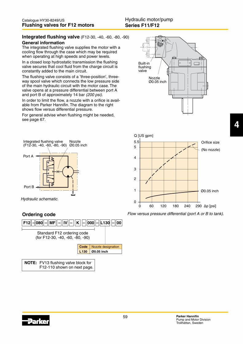
59 Parker HannifinPump and Motor DivisionTrollhättan, Sweden
Hydraulic motor/pumpSeries F11/F12
Catalogue HY30-8249/US
4
55.5
Q [US gpm]
290
4
240
3
180
2
120
1
600
0 Δp [psi]
Ø0.05 inch
Flow versus pressure differential (port A or B to tank).
General informationThe integrated flushing valve supplies the motor with a cooling flow through the case which may be required when operating at high speeds and power levels. In a closed loop hydrostatic transmission the flushing valve secures that cool fluid from the charge circuit is constantly added to the main circuit.
way spool valve which connects the low pressure side of the main hydraulic circuit with the motor case. The valve opens at a pressure differential between port A and port B of approximately 14 bar (200 psi).In order to limit the flow, a nozzle with a orifice is avail-able from Parker Hannifin. The diagram to the right shows flow versus differential pressure.For general advise when flushing might be needed, see page 67.
Hydraulic schematic.
F12_60_FV_install.epsLeif A./03-01-27
Built-influshingvalve
NozzleØ0.05 inch
Orifice size
(No nozzle)
F12_FV_schem.epsLeif A./03-01-27
Port A
Port B
Integrated flushing valve(F12-30, -40, -60, -80, -90)
NozzleØ0.05 inch
Flushing valves for F12 motors
Ordering code
F12 – 080 – MF – IV – K – 000 – L130 – 00
Standard F12 ordering code (for F12-30, -40, -60, -80, -90)
NOTE: FV13 flushing valve block for F12-110 shown on next page.
Integrated flushing valve (F12-30, -40, -60, -80, -90)
Code Nozzle designationL130 Ø0.05 inch
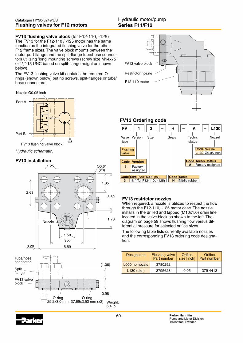
60 Parker HannifinPump and Motor DivisionTrollhättan, Sweden
Hydraulic motor/pumpSeries F11/F12
Catalogue HY30-8249/US
Code NozzleL130 Ø0.05 inch
Code Techn. statusA Factory assigned
Code SealsH Nitrile rubber
Code Size3 1¼" (for F12-110 / -125)
Code Version1 Factory
assigned
Flushing valve
F12_110_FV13_view.epsLeif A./03-01-27
FV13 valve block
Restrictor nozzle
F12-110 motor
FV13 flushing valve block (for F12-110, -125)The FV13 for the F12-110 / -125 motor has the same function as the integrated flushing valve for the other F12 frame sizes. The valve block mounts between the motor port flange and the split-flange tube/hose connec-
or 1/2"-13 UNC based on split-flange height as shown below).The FV13 flushing valve kit contains the required O-rings (shown below) but no screws, split-flanges or tube/hose connectors.
FV13 installation
FV13 restrictor nozzlesWhen required, a nozzle is utilized to restrict the flow through the F12-110, -125 motor case. The nozzle installs in the drilled and tapped (M10x1.0) drain line located in the valve block as shown to the left. The diagram on page 59 shows flushing flow versus dif-ferential pressure for selected orifice sizes. The following table lists currently available nozzles and the corresponding FV13 ordering code designa-tion.
Hydraulic schematic.F12_FV13_schem.epsLeif A./03-01-27
Port A
Port B
Nozzle Ø0.05 inch
FV13 flushing valve block
Flushing valves for F12 motors
FV13_squares.epsLeif A./03-01-28
FV13 Ordering code
FV 1 3 – H – A – L130
Valve Version Size Seals Techn. Nozzel type status
Designation Flushing valve Part number
Orifice size [inch]
Orifice Part number
L000 no nozzle 3780292
L130 (std.) 3795623 0.05 379 4413
(1.06)
0.98
1.85
3.62
1.73
1.50
3.27
5.590.28
2.63
1.25 Ø0.61(x8)
FV13_install.epsLeif A./03-01-27
Nozzle
Weight:6.4 lb
Tube/hoseconnector
Splitflange
FV13 valveblock
O-ring29.2x3.0 mm
O-ring37.69x3.53 mm (x2)

61 Parker HannifinPump and Motor DivisionTrollhättan, Sweden
Hydraulic motor/pumpSeries F11/F12
Catalogue HY30-8249/US
4
Port A
Port B
Pressure relief valve for F12-motors
Diagram for PLC082 pressure relief valves integrated in F12-030
∆p ∆p Pressure override characteristic(bar) (psi)
300 4351
500 7252
400 5802
100 1450
200 2900
0
6.60 13.20 19.81 26.420 25 50 75 100
Diagram for PLC182 pressure relief valves integrated in F12-040 and F12-060
∆p ∆p Pressure override characteristic(bar) (psi)
25 12550 15075 175100 20000
300 4351
500 7252
400 5802
100 1450
200 2900
6.60 13.20 19.81 26.42 33.02 39.63 46.23 52.83
Integrated pressure relief valve ( F12-030, -040, -060 )Integrated pressure relief valves are available for F12-030, F12-040 and F12-060. These are designed to protect the motor from short duration pressure spikes. The motor could be ordered with non-adjustable pres-sure setting between 210 - 420 bar (3050 - 6090 psi). The motor has to be ordered as unidirectional, L or R, and this is specified in the ordering code as example below.
F12-030-MS-SV-S-000-P28L-00P=Pressure relief valve, 28 = 280 bar, L = left
Possible pressure settings
Code Pressure bar
Pressure psi
21 210 (3050)23 230 (3340)25 250 (3625)28 280 (4060)30 300 (4350)33 330 (4785)35 350 (5075)38 380 (5510)40 400 (5800)42 420 (6090)
q (l/min) (US gpm)
q (l/min) (US gpm)

62 Parker HannifinPump and Motor DivisionTrollhättan, Sweden
Hydraulic motor/pumpSeries F11/F12
Catalogue HY30-8249/US
Code Serial number00 Factory assigned
Code Port size1 3/4" For: F12-30, -40, -602 1" For: F12-80, -903 1/4" For: F12-110 , -125
Pressure relief/make-up valveblock
SR pressure relief anti-cavitation valveThe SR pressure relief/make-up valve block for series F12 motors is designed to protect the motor and the main hydraulic lines from short duration pressure spikes. The valve block also provides an excellent make-up function.The valve block installs directly on the motor port flange, and is available in two sizes:1 3/4" for F12-30/-40/-602 1" for F12-80, -90 3 1 for F12-110 , -125The SR valve block consists of a housing containing two high pressure relief cartridges and two separate check valves for anti-cavitation. Cartridges are available in non-adjustable pressure settings between 280 and 420 bar (4000 and 6000 psi respectively).A make-up port (G) is also provided. In certain operating conditions, the motor (when operating as a pump) may cavitate because of insufficient inlet pressure. To prevent this, the G port should be pressurized. Contact Parker Hannifin for further information.
size 1 (3/4") is 0.45 bar (6.5 psi) at 175 l/min (45 gpm), and on size 2 (1") 0.7 bar (10 psi) at 250 l/min (65 gpm).
NOTE: The valve block includes main port O-rings (facing the motor) but no mounting screws.
SR valve block location.
SR valve block schematic.F12_SR_schem_SE.epsLeif A./03-01-27
Port B
Port A
Port G SR valve block F12 motor
F12_SR_install.epsLeif A./03-01-31
Port G
SR valve block
Pressure relief/anticav. valve for F12-motors
SR_SV_squares.epsLeif A./03-01-29
Ordering code
SR 1 – / – 00 – H F – A
Valve Version Port Serial Seals Threads Techn. function size Pressure settings number status
Code Version1 Factory assigned
Code Pressure settings (A/B ports) [bar]280, 300, 330, 350, 380, 400 or 420
Code SealsH Nitrile rubber
Code Threads (port G)F Metric
Code Techn. statusA Factory assigned
Pressure bar
Pressure psi
280 (4060)300 (4350)330 (4785)350 (5075)380 (5510)400 (5800)420 (6090)

63 Parker HannifinPump and Motor DivisionTrollhättan, Sweden
Hydraulic motor/pumpSeries F11/F12
Catalogue HY30-8249/US
4
Pressure relief/anticav. valve for F12-motors
SV pressure relief valveGeneral informationThe SV pressure relief valve block for series F12 motors is designed to protect the motor and adjacent hydraulic components from short duration pressure peaks. It installs directly on the motor port flange and is available in two sizes:
3/4" for F12-30/-40/-60
The valve block consists of a housing containing two high pressure relief cartridges with anti-cavitation func-tion. Cartridges are available in non-adjustable pressure settings between 280 and 420 bar (4060 and 6090 psi).A make-up/drain port, L, is also provided. In certain operating conditions the motor may cavitate because of in-sufficient inlet pressure. To prevent this, the L port can be pressurized. When there is a risk of over-heating, the L port can also be utilized to take out part of the flow for cooling. Contact Parker Hannifin for further information.
size 1 (3/4") is 0.45 bar (6,5 psi) at 175 l/min (45 gpm), and on size 2 (1") 0.7 bar (10 psi) at 250 l/min (65 gpm).
NOTE: - The valve block includes main port O-rings (facing the motor) but no mounting screws. - The valve blocks can be used on all versions of series F12 motors.
SV valve block installed on an F12 motor.
Hydraulic schematic.
F12_80_SV_install.epsLeif A./03-01-31
SV pressure reliefvalve block
F12_SV_schematic.epsLeif A./03-01-29
(F12)SV valve block
Port A
Port B
SR pressure relief anti-cavitation valve, Dimensions
C L M
D
E
FA φ P(x6)
K
G
H
B
J
SR11_install.epsLeif A./03-01-27
Checkvalve
Reliefvalvecartridge
Facingthe motor
Ports Ports
Nthread
Port L
Port G(size 1 and 2)
M22x1.5*; min 0.63 deep
* Metric thread
Dim. [inch]
Size 1 (3/4")
Size 2 (1")
Size 3 (1¼")
A 2.17 2.24 2.24B 2.17 2.17 0.98C 1.26 1.26 1.02D 6.18 6.30 6.30
2.60 2.95 3.27F 0.94 1.09 1.25G 2.00 2.25 2.63H 4.06 4.29 3.46J 5.51 5.91 5.31K 0.71 0.71 -L 0.71 0.71 0.71M 3.09 3.15 -N M10
x18M12 x20
M14 x23
P 0.43 0.51 0.61
Weight Size 1 (3/4")
Size 2 (1")
Size 3 (1¼")
[lb] 16.3 20.1 18.8

64 Parker HannifinPump and Motor DivisionTrollhättan, Sweden
Hydraulic motor/pumpSeries F11/F12
Catalogue HY30-8249/US
Pressure reliefvalve
Ordering code
SR_SV_squares.epsLeif A./03-01-29
SV 1 – / – 00 – H F – A
Valve Version Port Serial Seals Threads Techn. function size Pressure setting number (port L) status
Dim. [inch] SV11 SV12A 2.80 2.87B 1.22 1.22C 1.41 1.61D 1.85 2.01
5.12 5.00F 2.60 2.95G 0.94 1.09H 2.00 2.25J 3.90 4.29K 0.43 0.51
Weight [lb] 9.3 11.0
Code Port size1 3/4" F12-30, -40, -602 1" F12-80, -90
Code Version1 Factory assigned
Code Pressure settings (A/B ports) [bar]280, 300, 330, 350, 380, 400 or 420
Code Serial number00 Factory assigned
Code SealsH Nitrile rubber
Code Threads (port L)F Metric
Code Techn. statusA Factory assigned
SV pressure relief valve, Dimensions
Pressure bar
Pressure psi
280 (4060)300 (4350)330 (4785)350 (5075)380 (5510)400 (5800)420 (6090)
SV_install.epsLeif A./03-01-27
A
B
F
E
G
Ø K (x8)
H
J
D
C
Facingthe motor
Port BPort A
Make-up port L(M22x1.5 metric thread)
Port A Port Brelief valve cartr.

65 Parker HannifinPump and Motor DivisionTrollhättan, Sweden
Hydraulic motor/pumpSeries F11/F12
Catalogue HY30-8249/US
4
F12_speed_sensor.epsLeif A./020204
Speed sensor
A speed sensor kit is available for series F11/F12. A ferrostat differential (Hall-effect) sensor installs in a separate, threaded hole in the F11/F12 bearing housing .On F12 the speed sensor is directed towards the ring gear. On F11 the speed sensor is directed towards the pistons. The sensor output is a 2 phase shifted square wave signal within a frequency range of 0 Hz to 15 kHz.NOTE: - The motor bearing housing must be prepared for the speed pick-up; refer to the F11/F12 ordering codes on pages 12-14(F11) and 43-45 (F12). - On F11 the pistons position must be known before mounting. - Additional information is provided in the marketing information HY30-8301/UK. - The speed sensor is also shown in the illustrations on pages 17 to 37 and 46 to 57.Part number for Speed sensor is 3785190.
Speed sensor
F12 with speed sensor.
F11-14 with speed sensor.
Speed sensor

66 Parker HannifinPump and Motor DivisionTrollhättan, Sweden
Catalogue HY30-8249/US Hydraulic motor/pumpBLA Boost units Series F11/F12
BLAGeneral informationThe BLA boost unit simplifies the building of closed or semi-closed hydrostatic transmissions.
Main features are:
corresponding valves in many applications
speed
(106 USgpm)
transmission.
Typical applications:
DescriptionIn a closed circuit hydrostatic transmission, a charge pump is normally included with the main pump, pro-viding make-up fluid which replaces pump and motor volumetric losses. It also maintains sufficient pump inlet pressure to avoid cavitation.The BLA boost unit replaces the charge pump in many applications, when the following conditions are met:- The max-to-min pump flow ratio does not exceed 2:1- System pressure changes gradually without frequent and pronounced pressure peaks- The line length between pump and boost unit is relatively short.There are two basic sizes of the BLA boost unit: - BLA 4 (to 160 l/min (42 US gpm) pump flow) - BLA 6 (to 400 l/min (106 US gpm) pump flow).The main part of the unit is an aluminium housing with a built-in nozzle and an injector; refer to the cross section to the right. When fluid flows from the motor outlet port through the unit and to the pump inlet port, the increased fluid velocity between the nozzle and injector creates a low pressure zone causing additional fluid to be drawn from tank into the main circuit. Also, pressure increases after the injector, allowing the pump to be operated at speeds higher than the self-
The housing includes ports that should be connected to the pump and motor drain ports respectively. An additional bleed-off nozzle diverts approx. 10% of the main flow through the cartridge filter before being directed to the tank.
Oil coolingAn oil cooler is usually required in the hydraulic system, in order to remove the heat that is generated in the main circuit. A full-flow oil cooler should be installed in the return line between the motor and the boost unit.
BLA boost unit cross section.
1
4
3 5
6
72
BLA_install.epsLeif A./02-01-03
1. Pump
2. Motor
3. Boost unit (with injector and nozzle
4. Filter cartridge
5. Pressure relief valve
6. Full-flow filter (when required
7. Reservoir
Boost unit installation
For more information please see our technical catalogue BLA boost unit HY17-8224/UK
BLA_cross_section.epsLeif A./02-01-03
Injector From Nozzle tank
To pump
inlet
Frommotoroutlet
Bleed-offnozzleTo
filterFrom filter
to tank
BLA Boost Units

67 Parker HannifinPump and Motor DivisionTrollhättan, Sweden
Hydraulic motor/pumpSeries F11/F12
Catalogue HY30-8249/US
5
Series F12
Series F11
Clockwise rotation
Port A Port B
Counter clockwiserotation
Direction of rotationThe motor versions are bi-directional.The pump versions are uni-directional, allowing higher selfpriming speeds (refer to pages 9, 11 and 40, 42).The illustration to the right shows direction of flow ver-sus shaft rotation. In a motor application, the shaft turns clockwise when port B (black arrow) is pressurized, and counter clockwise when port A (open arrow) is pressu-rized.In a pump application where the shaft turns clock-wise, port B is the inlet port and should be connected to tank; when the shaft turns counter clockwise, port A is the inlet port.
Hydraulic fluidsRatings and performance data for series F11/F12 are based on operating with good quality, contamination-free, petroleum-based fluids.Hydraulic fluids type HLP (DIN 51524), automatic transmission fluids type A, or API CD engine oils can be used.Fire resistant fluids (when used under modified operat-ing conditions) and synthetic fluids may also be suitable.
Operating temperatureThe following temperatures should not be exceeded (type V FPM shaft seals):Main circuit 80 °C 176 °FDrain circuit: 115 °C 239 °F.NBR shaft seals (type N) can be used to 90 °C 194 °F drain fluid temperature.NOTE: The temperature should be measured at the utilized drain port.Continuous operation may require case flushing in order to meet the viscosity and temperature limitations. The following table shows operating speeds, above which flushing is usually required, as well as suggested flow through the case.
F11/F12 in series operation When running F11/F12 in series at higher pressure levels, Please contact Parker Hannifin for further information.
NOTE:When operating the F11/F12 as a pump above the selfpriming speed (valid for both the pump and motor versions), the inlet must be sufficiently pres-surized. Increased noise and deteriorating perform-ance may otherwise be experienced.
Installation information
Frame size Speed [rpm] Flow [l/min] Flow [gpm]
F11-5 5500 1 - 2 0.25-0-5
F11-6 4500 2 - 3 0.5-0.8
F11-10 4500 2 - 3 0.5-0.8
F11-12 4500 2 - 3 0.5-0.8
F11-14 4500 2 - 3 0.5-0.8
F11-19 4000 2 - 4 0.5-1.0
Frame size Speed [rpm] Flow [l/min] Flow [gpm]
F12-30 3500 4 - 8 1.0-2.1
F12-40 3000 5 - 10 1.3-2.6
F12-60 3000 7 - 14 1.9-3.7
F12-80 2500 8 - 16 2.1-4.2
F12-90 2500 8 - 16 2.1-4.2
F12-110 2300 9 - 18 2.4-4.8
F12-125 2300 9 - 18 2.4-4.8
F12-150 2200 10 - 20 2.6-5.2
F12-250 1800 12 - 22 3.2-5.8

68 Parker HannifinPump and Motor DivisionTrollhättan, Sweden
Hydraulic motor/pumpSeries F11/F12
Catalogue HY30-8249/USInstallation information
ViscosityThe ideal operating range is15 to 30 mm2/s [cSt]. At operating temperature, the viscosity (of the drain fluid) should be kept above 8 mm2/s [cSt]. At start-up, the viscosity should not exceed 1000 mm2/s [cSt]
FiltrationTo obtain the highest service life of the F11/F12, the fluid cleanliness should meet or exceed ISO code 20/18/13 (ISO 4406). During normal operating conditions, a 10 µm (absolute) filter is recommended.
Case pressureThe service life of the shaft seal ring is affected by the speed of the motor and the case drain pressure and it can decrease with an increase in the frequency of pressure peaks. Note, seal life can be shorter at unfavourable operating conditions (high temperature, low oil viscosity, contami-nated oil).The table below shows recommended case pressure as a function of shaft speed.
The case pressure must be equal to or greater than the external pressure on the shaft seal ring.
To secure correct case pressure and lubrication, a spring loaded check valve, 1-3 bar (14.5 - 43,5 psi), in the drain line (shown on next page) is recommended.
Note.Contact Parker Hannifin for information when operating at high speeds.
Shaft speed [rpm] 1500 3000 4500 6000 max
F11-5, -6, -10, -12, -14, -19
[bar] [psi]
0.5 - 10 7.3-145
0.5 - 7.0 7.3-102
1.0 - 5.0 14.5-72
2.0 - 5.0 29-72
3.0 - 5.0 43-72
F12-30, -40, -60, -80, -90
[bar] [psi]
0.5 - 8 7.3-116
0.5 - 6.0 7.3-87
1.0 - 4.5 14.5-
2.0 - 4.0 29-58 -
F12-110, -125, -150, -250
[bar] [psi]
0.5 - 6 7.3-87
1.0 - 4.0 14.5-58
2.0 - 4.0 29-58 - -

69 Parker HannifinPump and Motor DivisionTrollhättan, Sweden
Hydraulic motor/pumpSeries F11/F12
Catalogue HY30-8249/US
5
Spring loaded check valve
1-3 bar 14.5-43,5 psi
Drain flow
F12_ports.epsLeif A./020204
Port C
Port E (F12-110 and -125)
Port D
Drain flow
Flushing flow (when required)
Recommended 1-3 bar
14.5-43,5 psi
Case drain connectionsSeries F11/F12 have two drain ports, C and D, while F12-110 and -125 have an additional port, E.The uppermost drain port (such as port C in the illustra-tion below) should always be utilized.
a spring loaded check valve should be installed in the drain line in order to insure a sufficiently high oil level in the case.Preferably, the drain line should be connected directly to the reservoir.
Before start-upMake sure the F11/F12 case as well as the entire hydraulic system is filled with a recommended fluid.The internal leakage, especially at low operating pres-sures, is not sufficient to provide lubrication at start-up.
NOTE:- To avoid cavitation and obtain a low noise level as well as reduced heat generation, tubes, hoses and fittings must be adequately dimensioned. - Preferably, the suction line flow speed should be 0.5 to 1 m/s (1.6 to 3.3 ft/s), and pressure line flow speeds 3 to 5 m/s (9.8 to 16.4 ft/s).
Installation information
Drain flow
Recommended 1-3 bar
14.5-43,5 psi
Drain flow
Recommended 1-3 bar
14.5-43,5 psi
Drain flow
Recommended 1-3 bar
14.5-43,5 psi

Catalogue HY30-8249/US. POD 02/2015, ZZ© 2015 Parker Hannifin Corporation. All rights reserved.
Your local authorized Parker distributor
Ed. 2
015-
01-1
2
Parker Hannifin Corporation Hydraulics Group6035 Parkland BoulevardCleveland, OH 44124phone 1 800-C PARKERwww.parker.com/hydraulics
Europe, Middle East, AfricaAE – United Arab Emirates, Dubai Tel: +971 4 8127100 [email protected]
AT – Austria, Wiener Neustadt Tel: +43 (0)2622 23501-0 [email protected]
AT – Eastern Europe, Wiener Neustadt Tel: +43 (0)2622 23501 900 [email protected]
AZ – Azerbaijan, Baku Tel: +994 50 22 33 458 [email protected]
BE/LU – Belgium, Nivelles Tel: +32 (0)67 280 900 [email protected]
BG – Bulgaria, Sofia Tel: +359 2 980 1344 [email protected]
BY – Belarus, Minsk Tel: +48 (0)22 573 24 00 [email protected]
CH – Switzerland, Etoy Tel: +41 (0)21 821 87 00 [email protected]
CZ – Czech Republic, Klecany Tel: +420 284 083 111 [email protected]
DE – Germany, Kaarst Tel: +49 (0)2131 4016 0 [email protected]
DK – Denmark, Ballerup Tel: +45 43 56 04 00 [email protected]
ES – Spain, Madrid Tel: +34 902 330 001 [email protected]
FI – Finland, Vantaa Tel: +358 (0)20 753 2500 [email protected]
FR – France, Contamine s/Arve Tel: +33 (0)4 50 25 80 25 [email protected]
GR – Greece, Athens Tel: +30 210 933 6450 [email protected]
HU – Hungary, Budaoers Tel: +36 23 885 470 [email protected]
IE – Ireland, Dublin Tel: +353 (0)1 466 6370 [email protected]
IT – Italy, Corsico (MI) Tel: +39 02 45 19 21 [email protected]
KZ – Kazakhstan, Almaty Tel: +7 7273 561 000 [email protected]
NL – The Netherlands, Oldenzaal Tel: +31 (0)541 585 000 [email protected]
NO – Norway, Asker Tel: +47 66 75 34 00 [email protected]
PL – Poland, Warsaw Tel: +48 (0)22 573 24 00 [email protected]
PT – Portugal, Leca da Palmeira Tel: +351 22 999 7360 [email protected]
RO – Romania, Bucharest Tel: +40 21 252 1382 [email protected]
RU – Russia, Moscow Tel: +7 495 645-2156 [email protected]
SE – Sweden, Spånga Tel: +46 (0)8 59 79 50 00 [email protected]
SK – Slovakia, Banská Bystrica Tel: +421 484 162 252 [email protected]
SL – Slovenia, Novo Mesto Tel: +386 7 337 6650 [email protected]
TR – Turkey, Istanbul Tel: +90 216 4997081 [email protected]
UA – Ukraine, Kiev Tel: +48 (0)22 573 24 00 [email protected]
UK – United Kingdom, Warwick Tel: +44 (0)1926 317 878 [email protected]
ZA – South Africa, Kempton Park Tel: +27 (0)11 961 0700 [email protected]
North AmericaCA – Canada, Milton, Ontario Tel: +1 905 693 3000
US – USA, Cleveland (industrial) Tel: +1 216 896 3000
US – USA, Elk Grove Village (mobile) Tel: +1 847 258 6200
Asia PacificAU – Australia, Castle Hill Tel: +61 (0)2-9634 7777
CN – China, Shanghai Tel: +86 21 2899 5000
HK – Hong Kong Tel: +852 2428 8008
ID – Indonesia, Tangerang Tel: +62 21 7588 1906
IN – India, Mumbai Tel: +91 22 6513 7081-85
JP – Japan, Fujisawa Tel: +81 (0)4 6635 3050
KR – South Korea, Seoul Tel: +82 2 559 0400
MY – Malaysia, Shah Alam Tel: +60 3 7849 0800
NZ – New Zealand, Mt Wellington Tel: +64 9 574 1744
SG – Singapore Tel: +65 6887 6300
TH – Thailand, Bangkok Tel: +662 186 7000
TW – Taiwan, New Taipei City Tel: +886 2 2298 8987
VN – Vietnam, Ho Chi Minh City Tel: +84 8 3999 1600
South AmericaAR – Argentina, Buenos Aires Tel: +54 3327 44 4129
BR – Brazil, Cachoeirinha RS Tel: +55 51 3470 9144
CL – Chile, Santiago Tel: +56 2 623 1216
MX – Mexico, Toluca Tel: +52 72 2275 4200
Parker Worldwide