hydraulic excavator - marubeni komatsu...hydraulic excavator engine power 578 kw / 775 hp @ 1.800...
TRANSCRIPT

HYDRAULIC EXCAVATOR
ENGINE POWER578 kW / 775 HP @ 1.800 rpm
OPERATING WEIGHT115.900 - 118.300 kg
BUCKET CAPACITY6,7 m³
PC1250-11
PRELIMINAR
Y

2
Walk-Around
ENGINE POWER578 kW / 775 HP @ 1.800 rpm
OPERATING WEIGHT115.900 - 118.300 kg
BUCKET CAPACITY6,7 m³

3
PC1250-11
Walk-Around
Ecology & Economy Features• Komatsu’s new U.S. EPA Tier 4 Final emission
regulations-compliant engine NEW
• Fuel consumption reduced up to 7% (Comparison of PC1250-11 P mode and PC1250-8 P mode) NEW
• Further promotion of cleanliness and economy
• Auto idle stop function NEW
KOMTRAX Plus• Increased operational data and fuel savings
A maintenance program for Komatsu customers
EXCEPTIONAL WORKABILITY AND ENVIRONMENTAL PERFORMANCE
Operator Comfort• Comfortable working environment
Workability & Reliability Features• Productivity increased up to 8%
(Comparison of PC1250-11 P+ mode and PC1250-8 P mode) NEW
• Large digging force
• Enhanced efficiency due to powerful and smooth work
• Highly durable and reliable Komatsu designed components
Safety Features• Operator’s cab OPG level 2 (ISO 10262) NEW
• Lock lever auto lock function NEW
• Rear and side view monitor system NEW
• Meticulous safety accessories throughout
• Hydraulically operated stairway NEW
• Emergency stop switch NEW
Information & Communication Technology• Machine monitor with evolutionary interface NEW
• High resolution, easy-to-use color monitor provides powerful support for energy saving operation
• Operator identity function provides improved machine management and production records NEW
• KomVision NEW
Easy Maintenance• New maintenance features provided throughout the
machine help reduce inspection time, maintenance work and also machine downtime
• Various kinds of maintenance information are displaced clearly on the monitor screen

EGR valveVGT
After cooler
EGR cooler
4
Ecology & Economy Features
Heavy-duty cooled Exhaust Gas Recirculation (EGR) systemThe system recirculates a portion of exhaust gas into air intake and lowers combustion temperatures, thereby reducing NOx emissions. Furthermore, while EGR gas flow is increased, by incorporating a high-efficiency and compactly designed cooling system, the sys-tem achieves a dynamic reduction of NOx, while helping reduce fuel con-sumption.
Komatsu’s New Emission Regulations-compliant EngineKomatsu provides a powerful and eco-nomical US EPA Tier 4 Final compliant engine with latest emission control technologies and fuel saving features.
Technologies Applied to New EngineHeavy-duty aftertreatment systemKomatsu Diesel Particulate Filter (KDPF) reduces Particu-late Matter (PM) by more than 80% when compared to Tier 3 levels. Special oxidation catalyst and extra fuel injec-tion in the exhaust stream can decompose accumulated soot in the KDPF filter by either active or passive regenera-tion.This system does not require any additional operator's ac-tion or interrupt normal operation. Electronic control system
The electronic control system performs high-speed pro-cessing of all signals from sensors installed in the vehicle and engine to ensure total control of equipment in all conditions of use. Conditions of the engine are displayed via an on-board network on the monitor inside the cab, providing necessary information to the operator. Further-more, managing the information via KOMTRAX Plus helps customers engage in appropriate maintenance.
Variable Geometry Turbocharger (VGT) systemThe VGT system features Komatsu design hydraulic technology for variable control of air-flow and sup-plies optimal air according to load conditions. The upgraded version realizes better exhaust temperature management.
Komatsu Closed Crankcase Ventilation (KCCV) Crankcase emissions (blow-by gas) are passed through a CCV filter. The oil mist trapped in the filter is returned back to the crankcase while the filtered gas is returned to the air intake.
KDPF
KCCV
VGT
Cooled EGR
1
2
3
4CG image
1
3
4
2
Exhaust air
Variable nozzle
Intake air

5
PC1250-11
Ecology & Economy Features
Hydraulic variable speed fan (Reversible)Working mode selectableECO guidanceECO gauge & fuel consumption gauge
High Pressure Common Rail (HPCR) fuel injection system The system is designed to achieve an optimal injection of high-pressure fuel by means of computerized control, thereby bringing close to complete combustion to reduce Particulate Matter (PM) emissions.
Further Promotion of Cleanliness and Economy – Auto Idle Stop Function When the engine has been idling for certain time, the engine stops automatically to reduce unnecessary fuel consumption and exhaust emissions. The duration before the engine shutdown can be easily programmed.
Common rail
Supply pumpController
Injector
5
ECO gauge
Fuel consumption
gauge
ECO guidance

6
Workability & Reliability
Two-mode Setting for BoomSmooth mode provides easy operation for gathering blasted rock and scraping operations. When maximum digging force is needed, switch to Power mode for more effective excavating.
Large Digging ForceThanks to the high engine output and an excellent hydrau-lic system, this machine delivers a powerful digging force.
Heavy Lift ModeGives the operator 10% more lifting force on the boom when needed for handling rock or heavy lifting applica-tions.
Swing Priority SettingThe swing priority setting allows the operator to use the same easy motion for 180° loading as 90° loading opera-tions. By altering the oil flow, this setting allows you to select either boom or swing as the priority for increased production.
412 kN (42,0 t)
Maximum arm crowd force (ISO 6015)
479 kN (48,8 t)
570 kN (58,1 t)
Maximum bucket digging force (ISO 6015)
Large Drawbar Pull and Steering ForceSince the machine has a large drawbar pull and a highsteering force, it demonstrates excellent mobility even when it is being used on inclined sites.
Shockless Boom ControlThe PC1250-11 boom circuit features a shockless valve(double-check slow return valve) to automatically reducesthe amount of vibration present when operating the boom.Operator fatigue is reduced (which can improve safety and productivity), and spillage caused by vibration is mini-mized.
3.400 mm arm and ISO 6015 rating
Power Plus ModeThe PC1250-11 excavator is newly equipped with Power plus (P+) mode in addition to power (P) and economy (E) mode.P+ mode greatly increases the productivity.
P+ mode productivity
increased by 8%VS PC1250-8 P mode (90° swing and loading onto truck)
P mode fuel efficiency
increased by 8%VS PC1250-8 P mode (90° swing and loading onto truck)
Heavy Lift Mode Swing Priority Setting
PC1250-11PC1250SP-11
PC1250-11
PC1250SP-11
Smoothmode
Boom raise
Powermode
Extend andretract
for EU for NA

7
PC1250-11
Workability & Reliability
Fuel Pre-filter (with Water Separator)Fuel system reliability is even better with high efficiency fuel filter.
Bulkhead wall (fire wall)Prevents oil from splashing into the engine room even if hydraulic hoses are broken.
Boom Foot HosesThe boom foot hoses are ar-ranged under the boom foot to reduce hose bend during operation, extending hose life and improving operator safety.
Strengthened Boom and ArmThanks to the large cross-sectional structure employing a
high tensile strength steel with a thick plate, partition wall, etc., the boom and arm exhibit excel-lent durability and are highly resist-ant to bending and torsional stress.
Metal Guard RingsMetal guard rings protect all the hydraulic cylinders and improve reliability.
Circuit BreakerWith circuit breaker, the machine can be easily restarted after repair.
Sturdy UndercarriageThe undercarriage is strengthened to provide excellent reliability and durability when working on rocky ground or blasted rock.Sturdy guards shield the travel motors and pipings against damage from rocks.
O-ring Face SealHigh-pressure In-line FiltrationHeat-resistant WiringStrengthened Revolving Frame UnderguardSealed Connectors
Track roller guard (full length) (Optional)
Detecting clogging of hydraulic return filterrecommends filter exchange and prevents catastrophic damage of hydraulic system by informing operator the clogging of hydraulic return filter.The signal can be monitored via the KOMTRAX Plus.
Metal guard ring(Cast iron ring)
Piston ring
Wear ring
Large cross sectionalstructure boom
Arm dentpreventive plate
Partitionwall
Partitionwall
Wide widtharm
Wear plates
Rock protection
Bulkhead wall

8
Safety Features
Safety EquipmentEngine shut down secondary switch at base of seat to shutdown the engine.
Seat belt caution indicator
• Seat belt retractable• Beacon (optional)• Rear working light (LED• Emergency escape
hammer• Tempered & tinted glass• Large side-view &
sidewise mirrors• Slip-resistant plates • Lock lever• Travel alarm• Step light with timer• Horn interconnected with
warning light (Optional)• Bolt-on top guard,
OPG level 2 (ISO 10262) • Thermal and fan guards
Lock Lever – Auto Lock FunctionIf the work equipment lever is not in the neutral position when the hydraulic lock lever is released, the equipment is automatically stopped. The auto stop state is shown on the monitor screen.
Hydraulically operated stairwayThe new hydrauli-cally operated 45° stairway enables the operator to access the machine safely. If the stairway is not retracted, the equipment is auto-matically stopped (Lock lever auto lock function).
Emergency stop switchEmergency stop switches are provided at three points (in the operator's cab, on the right deck and left catwalk). They can be accessed easily in case of emergency.
Operator's CabThe machine is equipped with an operator's cab that conforms to OPG top guard level 2 (ISO 10262) for falling objects. The cab has high shock-absorption performance, featuring excellent durability and impact strength.
1 2 3
1
2
3

9
PC1250-11
Safety Features
Comfortable Working SpaceWide spacious cabThe PC1250-11 has a wider cab compared with the middle-sized excavator. It includes seat with reclining backrest. The seat height and longitudinal inclination are easily adjusted using a pull-up lever. You can set the appropriate opera-tional posture of armrest together with the console. Reclin-ing the seat further enables you to place it into the fully flat state with the headrest attached.
Low cab noiseThe newly-designed cab is highly rigid and has excellent sound absorption ability.
Arm rest with simple height adjustment functionThe addition of a knob and a plung-er to the armrest permits the height of the armrest to be easily adjusted without the use of tools.
Low vibration with cab damper mounting Automatic air conditioner (A/C)Pressurized cab Auxiliary input jackConnecting a regular audio instru-ment to the auxiliary jack allows the operator to hear the sound from the speaker installed in the cab.
Standard EquipmentSliding window glass (left side)
Remote intermittent wiper with windshield washer
Defroster (Conform to the ISO 10263-5)
High back air suspension seat with heat
Handling radio, ashtray
Cigarette lighter
Sun shield
Magazine box & cup holder
Open
Close
Operator Comfort

10
Information & Communication Technology
Operation record, fuel consumption history and ECO guidance recordThe ECO guidance menu enables the operator to check the operation record, fuel consumption history and ECO guidance record from the ECO guidance menu, using a single touch, thus enabling the total fuel consumption to be reduced.Support Efficiency Improvement – ECO
guidanceWhile the machine is operating, ECO guidance pops up on the monitor screen to notify the operator of the status of the machine in real time.
ECO gauge & fuel consumption gaugeThe monitor screen is provided with an ECO gauge and also a fuel consumption gauge which is displayed continu-ously. In addition, the operator can set any desired target value of fuel consumption (within the range of the green display), enabling the machine to be operated with better fuel economy.
Visual User MenuPressing the F6 key on the main screen displays the user menu screen. The menus are grouped for each function, and use easy-to-understand icons which enable the ma-chine to be operated intuitively.
Large High Resolution Liquid Crystal Display (LCD) Monitor –Machine Monitor with Evolutionary InterfaceThe interface has been redesigned to en-able the necessary information to be read and understood more easily, rear and side view camera images have been added to the default main screen. The interface has a function that enables the main screen to be switched, thus enabling the optimum screen for the particular work situation to be displayed.
1
4 5
9
6
2 3
Indicators1 Auto-decelerator2 Working mode3 Travel speed4 ECO gauge5 Camera display6 Engine coolant
temperature gauge7 Hydraulic oil
temperature gauge
8 Fuel gauge9 Service meter10 Clock11 Fuel consumption gauge12 Guidance icon13 Function switches14 Camera direction display
Basic operation switches1 Auto-decelerator2 Working mode selector3 Travel speed selector
4 Buzzer cancel5 Wiper6 Window washer
Operator Identification FunctionAn operator identification ID can be set for each operator, and used to manage operation information of individual ma-chines as KOMTRAX Plus data. Data sent from KOMTRAX Plus can be used to analyze operation status by operator as well as by machine.
4
5
6
1 2 3
7 8
11
PC1250-11
Equipment management supportKOMTRAX Plus enables expanded monitoring of the fleet via satellite and wireless LAN. Users can analyze “machine health” and performance from a remote location, on a near-real time basis. This includes component condition and trend data. By making this critical information readily accessible, KOMTRAX Plus is an effective tool in maximiz-ing productivity and lowering operating cost.
What• KOMTRAX is Komatsu’s remote equipment monitoring
and management system
• KOMTRAX is standard equipment on all Komatsu con-struction products
• KOMTRAX continuously monitors and records machine health and operational data
• Information such as fuel consumption, utilization, and a detailed history aids in making repair or replacement decisions
When• Know when your machines are running or idling and
make decisions that will improve your fleet utilization
• Detailed movement records ensure you know when and where your equipment is moved
• Up to date records allow you to know when maintenance was done and help you plan for future maintenance needs
Where• KOMTRAX data can be accessed virtually anywhere
through your computer, the web or your smart phone
• Automatic alerts keep fleet managers up to date on the latest machine notifications
Why• Knowledge is power – make informed decisions to man-
age your fleet better
• Knowing your idle time and fuel consumption will help maximize your machine efficiency
• Take control of your equipment – any time, anywhere
KOMTRAX PLUS
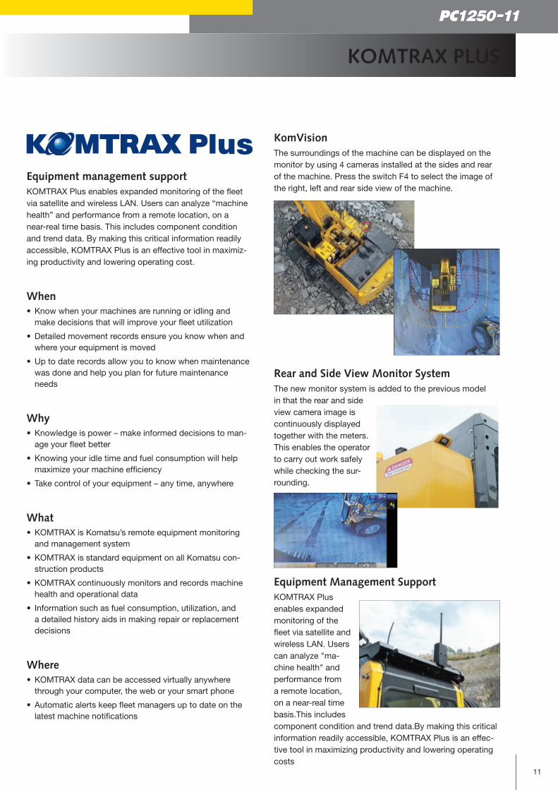
KomVisionThe surroundings of the machine can be displayed on the monitor by using 4 cameras installed at the sides and rear of the machine. Press the switch F4 to select the image of the right, left and rear side view of the machine.
Rear and Side View Monitor SystemThe new monitor system is added to the previous model in that the rear and side view camera image is continuously displayed together with the meters. This enables the operator to carry out work safely while checking the sur-rounding.
Equipment Management SupportKOMTRAX Plus enables expanded monitoring of the fleet via satellite and wireless LAN. Users can analyze "ma-chine health" and performance from a remote location, on a near-real time basis.This includes component condition and trend data.By making this critical information readily accessible, KOMTRAX Plus is an effec-tive tool in maximizing productivity and lowering operating costs

12
Easy Maintenance
A Wealth of Devices is Provided Throughout the Machine for Reducing Inspection and Maintenance Work and Also Machine Downtime.
1
2
7
4 3
9
8
9
5
6
Swing machinery(Swing motors)
Cab
Fuel tank
Pump
Engine
Hydraulictank
Hydraulicdriven fan
Controlvalve
After cooler
Oil coolerRadiatorAir-operated
greasing pump
Util
ity s
pace
A CoolantB Swing machinery oilC Hydraulic oilD Engine oilE Power Take Off (PTO) oil
1 Fuel filters2 Fuel pre-filters3 Engine oil filters4 Hydraulic drain filter5 Pilot filter6 Hydraulic return filters7 KCCV filter8 PTO strainer9 Swing motor cooling filters
Easy Checking and MaintenanceWide center walkway provides easy access to many inspec-tion and maintenance points. In addition, inspection and maintenance points are grouped to facilitate easy engine and hydraulic component checks.
Easy Cleaning of RadiatorThe hydraulically driven fan can reversed to facilitate cleaning of the cooling unit. In addition, this feature contributes to reducing warm-up time in low tempera-tures.

13
PC1250-11
Easy Maintenance
Walkway LightLighting to walkway provides easy and safety maintenance even in dark circumstances.
Easy Cleaning of Oil Cooler, A/C Condenser and Fuel CoolerHinged A/C condenser and fuel cooler provide easy ac-cess to each core.
for EU
Battery Disconnect SwitchA standard battery disconnect switch allows a technician to disconnect the power supply and lock out before servicing the machine.
for NA
Fuel Quick Charge System (Optional)Refueling port on the right front deck can be accessed from the ground level.
Long-life Oil, FilterUses high-performance filtering materials and long-life oil. Extends the oil and filter replacement interval.
Electric Priming PumpWide Catwalk, Large Step and HandrailsWashable Cab Floor MatDust Indicator with 5-step IndicationConvenient Utility Space
Maintenance Information
Aftertreatment devices regeneration automatic displayWhen it is necessary to carry out manual regeneration (the manual stationary regeneration) of the KDPF, the display automatically switches to the aftertreatment device regen-eration screen to inform the operator.
Aftertreatment device regeneration screen
“Maintenance time caution lamp” displayWhen the remaining time to maintenance becomes less than 30 hours*, the maintenance time monitor appears. Pressing the F6 key switches the monitor to the mainte-nance screen. * The setting can be changed within the range between 10 and 200 hours.
Maintenance screen
Engine oil & engine oil filter every 500 hours
Hydraulic oil every 5.000 hours
Hydraulic oil filter every 1.000 hours

14
Specifications
HYDRAULIC SYSTEM
Type Open-centre load sensing system
Main pump 3 variable displacement piston pumps supplying boom, arm, bucket, swing
and travel circuits
Maximum pump flow
Implement and travel 2 × 494 l/min
Swing 1 × 600 l/min
Sub-pump for control circuit Gear pump
Hydraulic motors
Travel 2 × axial piston motors with parking brake
Swing 2 × axial piston motors with swing holding brake
Relief valve settings
Backhoe 320 kg/cm²
Loading shovel 320 kg/cm²
Travel 350 kg/cm²
Swing 300 kg/cm²
Pilot circuit 32 kg/cm²
Hydraulic cylinders (no. of cylinders – bore × stroke):
Boom 2 – 225 mm × 2.390 mm
Arm 1 – 250 mm × 2.435 mm
Standard bucket 2 – 160 mm × 1.825 mm
SP bucket 2 – 160 mm × 1.950 mm
UNDERCARRIAGE
Construction H-leg frame with box section track frames
Track assembly
Type Fully sealed
Shoes (each side) 48
Tension Hydraulic
Rollers
Track rollers (each side) 8
Carrier rollers (each side) 3
SWING SYSTEM
Type 2 × hydraulic motors
Swing reduction Planetary gear
Swing circle lubrication Grease-bathed
Swing lock Oil disc brake
Swing speed 5,8 rpm
DRIVES AND BRAKES
Steering control 2 levers with pedals, giving full independent control of each track
Drive method Hydrostatic
Travel motor Axial piston motor, in-shoe design
Reduction system Planetary triple reduction
Gradeability 70%
Max. travel speeds
Lo / Hi 2,3 / 3,3 km/h
Maximum drawbar pull 70.000 kg
Service brake Hydraulic lock
Parking brake Oli disc brake
SERVICE REFILL CAPACITIES
Fuel tank 1360 l
Radiator 142 l
Engine oil 86 l
Swing drive 2 × 20 l
Hydraulic tank 670 l
Final drive (each side) 21 l
Power Take Off (PTO) 13,5 l
ENGINE
Model Komatsu SAA6D170E-7
Type 4-cycle, water-cooled, direct injection, turbocharged,
air-to-air charge air cooler, cooled EGR
Engine power
at rated engine speed 1.800 rpm
SAE J1995 578 kW / 775 HP
ISO 9249 / SAE J1349* (net engine power)
565 kW / 758 HP
No. of cylinders 6
Bore × stroke 170 × 170 mm
Displacement 23,15 l
Fan drive type Hydraulic
Engine emissions Exempt from EU exhaust emission regulations
*Net horsepower at the maximum speed of radiator cooling fan
519 kW / 696 HP
OPERATING WEIGHT (APPR.)
BACKHOEPC1250-11: Operating weight, including 9.100 mm boom, 3.400 mm arm, SAE J 296 heaped 5,0 m³ backhoe bucket, operator, lubricant, coolant, full fuel tank, and standard equipment.
PC1250SP-11: Operating weight, including 7.800 mm boom, 3.400 mm arm, SAE J 296 heaped 6,7 m³ backhoe bucket, full length roller guard, operator, lubricant, coolant, full fuel tank, and standard equipment.
Double grouser shoes
PC1250-11 PC1250SP-11
Operating weight
Ground pressure
Operating weight
Ground pressure
700 mm 115.900 kg 1,51 kg/cm² 118.300 kg 1,54 kg/cm²
1.000 mm 118.200 kg 1,08 kg/cm² –

A
4120
B4860
4995 6425
50
1780
4300
3490
700 3900
990
2260
4600
53505570
4965
4650
4810
15
PC1250-11
Specifications Dimensions & Performance Figures
MACHINE DIMENSIONS PC1250-11 PC1250SP-11
9,1 m boom 7,8 m boom
3,4 m arm 4,5 m arm 5,7 m arm 3,4 m arm
A Overall height 6.040 mm 6.460 mm 6.990 mm 6.265 mm
B Overall length 16.070 mm 16.100 mm 15.890 mm 14.840 mm
Max. capacity and weight have been calculated according to ISO 10567:2007.Please consult with your distributor for the correct selection of buckets and attachments to suit the application.
BACKHOE BUCKET, ARM AND BOOM COMBINATION
Bucket Capacity (Heaped) WidthWeight
(With Side Cutters)
Arm LengthISO 7451, PCSA CECE
Without SideCutters or Shrouds
With SideCutters or Shrouds
PC1250-11 (Use with 9,1 m Boom) 3,4 m 4,5 m 5,7 m
3,4 m3 3,0 m3 1.500 mm 1.670 mm 3.550 kg — n
4,0 m3 3,5 m3 1.710 mm 1.880 mm 3.820 kg n
5,0 m3 4,3 m3 2.050 mm 2.220 mm 4.370 kg n —
5,2 m3 4,5 m3 2.050 mm 2.110 mm 5.780 kg n —
PC1250SP-11 (Use with 7,8 m Boom) 3,4 m — —
6,7 m3 5,9 m3 2.280 mm 2.340 mm 6.500 kg n — —
These charts are based on over-side stability with fully loaded bucket at maximum reach.: General purpose use, density up to 2,1 t/m3 n: General purpose use, density up to 1,8 t/m3
: General purpose use, density up to 1,5 t/m3 —: Not useable

16
Working Range
2
1
3
0
4
5
6
7
8
9
10
11
12
13
14
-1
-2
-3
-4
-5
-6
-7
-8
-9
-10
0 1 2 3 4 5 6 7 8 9101112131415161718
H
GF
B
ED
C
A
2.4
-11
-12
(m)
(m)
WORKING RANGE PC1250-11 PC1250SP-11
9,1 m boom 7,8 m boom
3,4 m arm 4,5 m arm 5,7 m arm 3,4 m arm
A Max. digging height 13.400 mm 13.490 mm 13.910 mm 13.000 mm
B Max. dumping height 8.680 mm 9.000 mm 9.440 mm 8.450 mm
C Max. digging depth 9.350 mm 10.440 mm 11.590 mm 7.900 mm
D Max. vertical wall digging depth 7.610 mm 8.490 mm 9.480 mm 5.025 mm
E Max. digging depth of cut for 8' level 9.220 mm 10.340 mm 11.500 mm 7.745 mm
F Max. digging reach 15.350 mm 16.340 mm 17.450 mm 14.070 mm
G Max. digging reach at ground level 15.000 mm 16.000 mm 17.130 mm 13.670 mm
H Min. swing radius 7.965 mm 7.990 mm 8.150 mm 6.415 mm
SA
E J
1179
R
atin
g
Bucket digging force 422 kN43.000 kg
422 kN43.000 kg
343 kN35.000 kg
502 kN51.200 kg
Arm crowd force 392 kN40.000 kg
327 kN33.300 kg
281 kN28.700 kg
395 kN40.300 kg
ISO
601
5 R
atin
g
Bucket digging force 479 kN48.800 kg
479 kN48.800 kg
389 kN39.700 kg
570 kN58.100 kg
Arm crowd force 412 kN42.000 kg
337 kN34.400 kg
286 kN29.200 kg
412 kN42.000 kg

17
PC1250-11
Working Range Transportation Guide
Transportation volume (length x height x width)Specs shown include the following equipment: Backhoe: boom 9.100 mm, arm 3.400 mm, bucket 5,0 m3, shoes 700 mm double grouser
6.425 mm
mm 585
1.
1.222 mm
Work equipment assembly (Backhoe) Weight : PC1250 : 25,7 t
: 27,2 t (Heavy-duty version) PC1250SP : 28,0 t
Undercarriage
Weight : 31,4 t [15,7 t x 2] Weight : 32,2 t [16,1 t x 2] (With full length roller guard)
Boom
PC1250 : 11,2 t : 9.475 x 2.894 x 1.474 mm
PC1250SP : 11,1 t : 8.170 x 3.095 x 1.474 mm
Arm
PC1250 : 6,1 t : 4.895 x 1.626 x 890 mm
: 6,4 t : 4.895 x 1.626 x 890 mm (Heavy-duty version)
PC1250SP : 6,6 t : 4.914 x 1.683 x 890 mm
Bucket
PC1250 : 4,6 t : 2.700 x 2.100 x 2.050 mm
: 5,8 t : 2.580 x 2.276 x 2.250 mm (Heavy-duty version)
PC1250SP : 6,5 t : 2.527 x 2.420 x 2.520 mm
Arm cylinder
1,5 t
Boom cylinder
2,3 t [1,15 t x 2]
Upper structure
Width : 3.495 mmWeight : 39,9 t
OthersWeight : 17,8 t
3.490 mm
mm 0691
100 mm
1915 mm
mm 0582
845 mm620 mm
400 mm
mm 006
mm 5513
835 mm
Weight : 16,7 t
Length : 3.950 mm
Length: 3.810 mm
1.96
m 0m
105 mm
2.015 mm
1.160 mm
362 mm
mm 0662.
620 mm
347 mm
mm 5272.
6.520 mm
3.580 mm
915 mm
mm 0541.
572.
m 0m
1.830 mm

18
Lifting Capacity
PC1250-11 / BOOM LENGTH 9,1 M / LIFTING MODE: ON
9,1 m kg *22.750 21.750 *23.400 *23.400
6,1 m kg 21.850 18.000 22.450 18.550 *25.200 22.850 *28.000 *28.000 *32.850 *32.850
3,0 m kg 20.400 16.750 21.700 17.800 26.200 21.400 32.500 26.350 *40.050 33.500
0,0 m kg 21.000 17.150 21.150 17.300 25.250 20.500 31.100 25.050 40.350 32.000
-3,0 m kg 24.500 19.950 25.300 20.550 31.000 24.950 *40.300 32.050 *49.000 44.900 *41.250 *41.250
-6,1 m kg *26.000 *26.000 *30.200 *30.200 *37.300 *37.300
9,1 m kg *20.750 *20.750 *20.900 *20.900
6,1 m kg *20.350 18.000 *21.150 18.550 *22.450 *22.450 *25.000 *25.000 *29.350 *29.350
3,0 m kg 20.400 16.750 21.700 17.800 *24.900 21.400 *28.950 26.350 *35.650 33.500
0,0 m kg 21.000 17.150 21.150 17.300 25.250 20.500 *31.000 25.050 *37.800 32.000
-3,0 m kg *23.550 19.950 *24.650 20.550 *29.750 24.950 *35.750 32.050 *43.500 *43.500 *37.700 *37.700
-6,1 m kg *22.900 *22.900 *26.650 *26.650 *32.900 *32.900
Arm length12,2 m 10,7 m 9,1 m 7,6 m 6,1 m 4,6 m
3,4 m
Heavy Lift: ON
* Load is limited by hydraulic capacity rather than tipping.Ratings are based on SAE Standard No. 10567.Rated loads do not exceed 87% of hydraulic lift capacity or 75% of tipping load.Lifting capacity stated is based on lifting with bare arm. When lifting with additional equipment installed to the arm, please subtract the weight of all additional equipment from the values stated.
Weights without bucket
With 700 mm shoes
A
B
C
– Reach from swing centre
– Bucket hook height
– Lifting capacities
– Rating over front
– Rating over side
– Rating at maximum reach
Heavy Lift: OFF
3,4 m
9,1 m kg *15.900 *15.900 *18.550 *18.550
6,1 m kg *15.650 *15.650 *21.500 18.700 *22.900 *22.900 *25.200 *25.200
3,0 m kg *16.400 14.750 21.600 17.650 *26.100 21.350 *30.200 26.450 *36.900 33.850
0,0 m kg *18.300 14.950 20.700 16.850 24.850 20.100 30.750 24.650 39.850 31.500 *32.350 *32.350
-3,0 m kg 20.800 16.900 24.450 19.750 30.200 24.100 39.350 31.000 *50.850 43.400 *36.350 *36.350
-6,1 m kg *24.700 22.850 *28.150 25.000 *34.700 32.050 *42.550 *42.550 *53.100 *53.100
9,1 m kg *14.450 *14.450 *16.850 *16.850
6,1 m kg *14.250 *14.250 *19.100 18.700 *20.350 *20.350 *22.500 *22.500
3,0 m kg *14.900 14.750 *20.800 17.650 *23.150 21.350 *26.800 26.450 *32.800 *32.800
0,0 m kg *16.650 14.950 20.700 16.850 24.850 20.100 *29.750 24.650 *36.500 31.500 *29.550 *29.550
-3,0 m kg *20.400 16.900 24.450 19.750 *29.850 24.100 *36.150 31.000 *45.050 43.400 *33.150 *33.150
-6,1 m kg *21.750 *21.750 *24.800 *24.800 *30.650 *30.650 *37.550 *37.550 *46.850 *46.850
4,5 m
Heavy Lift: ON
Heavy Lift: OFF
4,5 m
B
A
C

19
PC1250-11
Lifting Capacity
9,1 kg *11.750 *11.750
6,1 kg *11.600 *11.600 *18.450 15.650 *19.450 19.050
3,0 kg *12.050 *12.050 18.150 14.850 21.700 17.800 *24.200 21.600 *27.750 26.950 *33.550 *33.550
0,0 kg *13.250 13.150 17.450 14.150 20.600 16.700 24.800 20.000 30.750 24.650 *39.350 31.550 *35.350 *35.350
-3,0 kg *15.700 14.450 20.050 16.200 24.000 19.250 29.700 23.650 38.750 30.400 *50.200 42.450
-6,1 kg *21.500 18.300 24.400 19.650 30.000 23.950 *37.400 30.850 *46.400 43.350
9,1 kg *10.650 *10.650
6,1 kg *10.500 *10.500 *16.650 15.650 *17.250 *17.250
3,0 kg *10.900 *10.900 *17.900 14.850 *19.300 17.800 *21.400 *21.400 *24.600 *24.600 *29.750 *29750
0,0 kg *12.000 *12.000 17.450 14.150 20.600 16.700 *24.050 20.000 *28.300 24.650 *34.850 31.550 *32.250 *32.250
-3,0 kg *14.250 *14.250 20.050 16.200 24.000 19.250 *29.600 23.650 *36.100 30.400 *45.800 42.450
-6,1 kg *19.500 18.300 *22.350 19.650 *27.150 23.950 *33.000 30.850 *40.950 *40.950
5,7 m
Lifting mode: ON
PC1250-11 / BOOM LENGTH 9,1 M / LIFTING MODE: ON
* Load is limited by hydraulic capacity rather than tipping.Ratings are based on SAE Standard No. 10567.Rated loads do not exceed 87% of hydraulic lift capacity or 75% of tipping load.Lifting capacity stated is based on lifting with bare arm. When lifting with additional equipment installed to the arm, please subtract the weight of all additional equipment from the values stated.
A
B
C
– Reach from swing centre
– Bucket hook height
– Lifting capacities
– Rating over front
– Rating over side
– Rating at maximum reach
Weights without bucket
With 700 mm shoes
Arm length13,7 12,2 10,7 9,1 7,6 6,1
9,1 kg *21.000 *21.000 *28.700 *28.700
6,1 kg *20.100 *20.100 27.800 22.950 *30.800 29.250 *34.900 *34.900 *42.200 *42.200
3,0 kg *21.050 19.800 26.750 21.950 33.550 27.350 *41.500 35.300
0,0 kg *24.250 20.600 26.050 21.250 32.200 26.050 41.950 33.450 *55.350 46.300
-3,0 kg *28.450 25.300 *30.450 26.250 *38.700 33.450 *47.850 46.650 *59.200 *59.200
-6,1 kg
9,1 kg *19.100 *19.100 *25.800 *25.800
6,1 kg *18.300 *18.300 *25.450 22.950 *27.600 *27.600 *31.350 *31.350 *37.950 *37.950
3,0 kg *19.150 *19.150 26.750 21.950 *30.850 27.350 *37.100 35.300
0,0 kg *22.050 20.600 26.050 21.250 *32.050 26.050 *39.000 33.450 *49.350 46.300
-3,0 kg *25.250 *25.250 *27.050 26.250 *34.400 33.450 *42.550 *42.550 *52.550 *52.550
-6,1 kg
3,4 m
Lifting mode: ON
PC1250SP-11 / BOOM LENGTH 7,8 M / LIFTING MODE: ON
Arm length12,2 10,7 9,1 7,6 6,1 4,6
Heavy Lift: OFF
5,7 m
Heavy Lift: OFF
3,4 m
B
A
C

Komatsu EuropeInternational N.V.Mechelsesteenweg 586B-1800 VILVOORDE (BELGIUM)Tel. +32-2-255 24 11Fax +32-2-252 19 81www.komatsu.eu
is a trademark of Komatsu Ltd. Japan.EENSS20360P 03/2018
Your Komatsu partner:
Standard and Optional Equipment
Printed in Europe – This specification sheet may contain attachments and optional equipment that are not available in your area. Please consult your local Komatsu distributor for items you may require. Materials and specifications are subject to change without notice.
AdBlue® is a registered trademark of Verband der Automobilindustrie e.V.
Further equipment on request
standard equipment optional equipment
ENGINEKomatsu SAA6D170E-7 turbocharged common rail direct injection diesel engine
Automatic engine warm-up system
Auto-deceleration function
Adjustable idle shutdown
Dry type air cleaner, double element
Fuel pre-filter with water separator
Variable speed cooling fan, hydraulic drive, reversible
Battery disconnect switch
Circuit breaker
Lever lock auto-lock
Alternator 24 V / 90 A
Starter motor 2 × 24 V / 11 kW
Batteries 2 × 12 V / 220 Ah
HYDRAULIC SYSTEM2 speed travel with auto shift
3-mode system (Power plus, Power, Economy)
Automatic swing holding brake
Fully hydraulic, with Open-Center Load-Sensing and engine speed sensing (Pump and engine mutual control system)
Heavy lift mode
In-line high pressure filters
Pressure Proportional Control (PPC) hydraulic control system
Shockless control system for boom
Two-mode setting for boom
CABINCab with fixed type front window
Heated, high-back air-suspended seat
12 Volt power supply
Automatic climate control system, with defroster
AM/FM radio
Auxiliary input (3,5 mm jack)
Engine shut down secondary switch
KomVision
Large high resolution LCD color monitor
Lock lever
Mirrors (RH,LH)
Rear & side view monitor system
Washable cab floor mat
Seat belt, 78 mm
Cab guards: Bolt-on top guard, OPG Level 2 (ISO 10262)
Cab guards: Full front guard, OPG Level 2 (ISO 10262)
OTHER EQUIPMENTCounterweight, 16.700 kg
Electric priming pump for fuel
Equipment Management Monitoring System
General tool kit
Grease gun, air pump
Hand rails & guard rails
Horn, air
KOMTRAX Plus
One-touch engine oil drainage
Preventive Maintenance (PM) tune-up service connector
Rear reflectors
Seat belt indicator
Slip-resistant plates
Travel alarm
Vandalism protection locks
Wide catwalk
Radiator and oil cooler dustproof net
Emergency stop SW, 3 (inside Cab, LH catwalk, RH deck)
Hydraulically operated stairway
Automatic greasing system (Lincoln 18L)
Beacon, 2 (Cab top, C/W top)
Coolant heater
Engine oil pan heater
Fuel quick charge system
Horn interconnected with warning light
LIGHTING SYSTEMWorking lights: 2 boom, 2 cab roof, 1 right front
Walkthrough light
Step light with timer
Rear working light (LED)
UNDERCARRIAGECarrier rollers, 3 (Each side)
Hydraulic track adjusters (Each side)
Track rollers, 8 (Each side)
Track shoes, 700 mm double grouser
Strengthened revolving frame underguards
Track frame undercovers (Centre)
Track guiding guards (Each side)
Travel motor guards
Track roller guard (Full length)
Shoes: 1.000 mm double grouser
WORK EQUIPMENTArms (Backhoe):
3.400 mm HD arm assembly
3.400 mm SP arm assembly
4.500 mm HD arm assembly
5.700 mm arm assembly
Booms (Backhoe):
7.800 mm SP boom assembly
9.100 mm boom assembly