hydraulic design of main canal headgate structure by model ... · hydraulic design of main canal ....
TRANSCRIPT

0
PAP 2 4. HYDRAULICS BRANCH OFFICIAL FILE COPY
WHEN BORROWED RETURN PROMPTLY
HYDRAULIC DESIGN OF MAIN CANAL
HEADGATE STRUCTURE
BY MODEL STUDY
by
a
J. A. Hufferd and T. J. Isbester, Engineers
Office of Chief Engineer
Bureau of Reclamation
United States Department of the Interior
Denver, Colorado
A paper to be presented at the Hydrau-
lics Division Conference, American Society
of Civil Engineers, Madison, Wisconsin,
August 24-26, 1966
4

HYDRAULIC DESIGN OF MAI:Q CANAL HEADGATE STRUCTURE BY MODEL STUDY
by J. A. Hufferd, M. ASCEl/ and T. J. Isbester2/
SYNOPSIS
This paper is a presentation of hydraulic model studies used to improve the original design of the underground stilling basin for the Navajo Main Canal headworks structure. A number of modifica-tions were developed to assure _good energy dissipation, freedom from violent backwater flows against the two radial gates, and smooth flow conditions into the 17--1/2-foot, 2-mile-long horse-shoe tunnel. Heads varied from 15 to 126.5 feet and discharges from 0 to 1,800 cfs (cubic feet per second). Use of 15° sloping chutes extending from gate chamber invert to basin floor instead of parabolic chutes eliminated most heavy surging. The horizon-tal gate chamber inverts were joined to the chutes with 16-foot radii of curvature. The change in floor alinement occurred in the high--pressure region upstream from the gate seats. A basin length of 89 feet provided the necessary energy dissipation. Vertical curtain walls to prevent excessive backflow against down-stream sides of the radial gates were placed with bottoms about 7 feet above the chutes and faces almost 31 feet doe--7nstream from the projected intercept of horizontal gate chamber inverts and the chutes.
Maximum flows at minimum reservoir elevation are attained by allowing a part of the flow to overtop the curtain walls. Four large baffle piers effectively turned the flow upward and increased energy dissipation rate without danger of cavitation. An underpass-type wave suppressor located at downstream end of the basin.pro-vided excellent flow conditions in the downstream tunnel.
DESCRIPTO?S-- *stilling basins/ *radial gates/ laboratory tests/ hydraulic jumps/ research and development/ gate seals/ cavitation/ baffles/ hydraulic gates and valves/ *energy dissipation/ instru-mentation/ hydraulics/ canals/ high pressures/ discharges/ hydrau-lic structures// transitions/•structures// wave velocity/ piers/ model tests/ hydraulic models/ chutes/ tunnels
IDENTIFIERS— *headworks/ curtain walls/ chute blocks/ backflows/ center piers/ design modifications/ horseshoe transitions/ *under-ground stilling basins/ wave suppressors/ spoilers
Supervising Civi Engineer, Canals Branch, Office of Chief Engineer, Bureau of Reclamation, Denver, Colorado. 2/Hydraulic Engineer, Hydraulic Laboratory Branch, Office of Chief Engineer, Bureau of Reclamation, Denver, Colorado.

INTRODUCTION
The Navajo Indian Irrigation Project is in the northwest corner of New Mexico (Figure 1). The headgate structure (Figures 2 and 3), which is the subject of this paper, will draw water from the reservoir created by the project's Navajo Dam on the San Juan River.
The inlet to the headgate is just upstream from the south end of the dam. The intake and trashrack portion of the structure is set into the sandstone of the canyon wall and is connected to the gate structure by a 166.5-foot-long, 18-foot-diameter conduit (Figure 2). The structure was designed to pass 1,800 cfs with the reservoir head varying from 15 to 126.5 feet. The discharge will be controlled by two 9-foot-wide by 12-foot- high radial gates which discharge into an underground stilling basin. Two 9- by 12-foot fixed-wheel gates are just upstream from the radial gates to provide emergency closure and to isolate the radial gates for normal maintenance work. A transition at the downstream end of the stilling basin directs the water into a gravity flow tunnel.
The tunnel, approximately 2 miles long, is 18 feet in diameter. The specifications design provided for either a 17-1/2-foot horseshoe-shaped section or an 18-foot circular section, and bids were received for each on a per foot basis at the contractor's option. The 18-foot-diameter section was selected because the contractor (Fenix and Scisson, Inc., of Tulsa, Oklahoma) elected to excavate with a tunneling machine. A Parshall flume, at the downstream end of the tunnel, measures the discharge. To main-tain the accuracy of the flume measurements, it was desirable to maintain a smooth, relatively wave-free water surface in the tunnel. An upslope at the beginning of the Parshall flume causes a backwater effect in the circular tunnel for all discharges and for all discharges but the maximum for a tunnel with horseshoe section (Figure 7).
Releases through the headworks will average 508,000 acre-feet annually, which will supply water to 110,630 acres of irrigable land. The water will travel through an intricate distribution system approximately 150 miles long. The system will comprise tunnels, siphons, and lined and unlined canals. About 75 percent of the land will be supplied by gravity flow; the remaining por-tion by distribution of pumped flow.
The project lands proposed for irrigation development are on an elevated plain south of the San Juan River in northwestern New Mexico. Irrigation is necessary in the San Juan River Basin
2

for crop production because of the very limited rainfall. Pres-ently, all of the project lands are undeveloped and, due to the lack of moisture, are used only for grazing.
The Bureau of Reclamation is responsible for the design and con-struction of irrigation facilities from creation of the headwater in the reservoir behind Navajo Dam down to the turnouts to in-dividual farm units. The development of the farm units is the responsibility of the Bureau of Indian Affairs and the Navajo Tribe.
PRELIMINARY DESIGN
The preliminary arrangement of the headgate structure prior to the model study is shown in Figure 2. This arrangement was based partly on experience with similar structures presently in opera-tion, and partly on previous laboratory study of stilling basins in general.1/
The radial type of control gates were selected to provide close regulation of the discharge. The fixed-wheel gates are for emergency closures. It was hoped that the radial gates could be rated initially so that they could be set for the desired dis-charge based on the head and gate opening. A Parshall flume at the end of the 2-mile-long tunnel was provided as a permanent rating device for the gates and a recording station for measure-ment of instantaneous and total flow. The time lag between ad-justment of the gates and response at the Parshall flume made the initial rating of the gates very desirable from an operational standpoint. Eventually, if required, telemetering equipment may be installed to indicate, in the gate control house, the measured flow through the Parshall flume.
A model study of the headgate structure was deemed advisable because:
1. The high head, from the reservoir, on the radial gates raised a question relative to the extent and possible damage due to gate vibration.
2. The discharge conditions from the gates into the stilling basin were not exactly similar to any that had previously been constructed or to those tested in previous laboratory studies.1/
1 Numbers refer to items in Bibliography.
3

3. It was desirable to have tranquil flow into the tunnel from the stilling basin.
4. Discharge coefficients for the radial gates for variable head and variable gate opening were necessary for rating the gates.
THE MODEL
The tests were conducted in a 1:16 scale model of the outlet works (Figures 4, 5, and 6). The model included a 13-1/2-inch-inside-diameter inlet pipe 16 diameters long, a 3-foot-long, round-to-rectangular transition, the gate chamber which includes slots for the fixed-wheel gates, two radial gates (9- by 12-foot prototype), a divided stilling basin, a transparent plastic transition from the basin to the downstream horseshoe tunnel, 6 diameters of horse-shoe tunnel, and a tailgate for regulating the water surface elevation.
Flow was supplied by the main laboratory pumping system through calibrated 4- and 6-inch Venturi meters.
The radial gates were made of sheet metal with gages chosen to correspond in scale to the approximate dimensions of the prototype gates (Figu'res 4 and 6). The bottom surface of each gate was equipped with a 1/16-inch-thick solid rubber seal. The side and top seals of solid neoprene, were attached to the gate seat structure. Two stem lifting screws controlled the position of the gates.
The gate chamber was made of brass plate and was flanged to fit the rectangular end of the transition and the stilling basin (Figure 5) .
The right side of the stilling basin and the downstream transition were made of transparent plastic to provide visual inspection and to permit obtaining photographic records of flow conditions. The basin was contained in an open, rectangular box. Chutes leading from the gate chamber to the basin floor were separately fabri-cated and inserted within the main box.
The model, as initially designed, conformed in most details to the first prototype design. Later modifications to the model and to the prototype resulted in several minor deviations. The con-figuration of the final gate chamber roof and the roof of the model between the fixed-wheel gates and the radial gates differed
4

as shown in Figure 17. The 19-foot diameter of the initial model horseshoe tunnel on the downstream end of the basin was retained as compared to the 17-foot 6-inch diameter selected after the maximum discharge requirement was reduced from 2,120 to 1,800 cfs. The arched roof of the stilling basin was not installed for final testing because previous tests showed that no adverse effects resulted from its use.
INSTRUMENTATION
Piezometers were placed in the model at various locations to ob-tain desired pressure head readings and to detect adverse pres-sure conditions. Most of the pressure measurements were made with single-leg, water-filled manometers. Diaphragm-type pressure cells and electronic recording equipment were used to obtain instantan-eous pressures at critical piezometer locations.
The upstream head was measured with a single-leg water manometer set so that the zero head level was at the gate invert elevation. The column was attached by a ring of four piezometers to the cir-cular inlet pipe 1 diameter upstream (Station 4+18.50) from the round-to-rectangular transition.
Records of water surface conditions in the downstream tunnel were obtained with a capacitance-type wave probe and electronic record-ing equipment.
INVESTIGATION
Most of the tests were made with the most severe operating con-ditions that could occur. These conditions were maximum discharges for either double- or single-gate operation at maximum head. Tests were also made at lesser discharges and heads. The tailwater ele-vation was adjusted to conform to Curve A which was computed by Manning's formula using an "n" of 0.013 (Figure 7).
During the course of the study, the maximum design discharge was changed from 2,120 to 1,800 cfs. This changed the operating range of Froude numbers from initial values between 14.4 and 1.36 to final values between 10.7 and 2.16.
Performance of the basin as initially designed was unsatisfactory (Figure 9). The jump was very unstable and large objectional oscillations or surges from the jump carried into the downstream tunnel. Also, intermittent heavy backflow struck the downstream sides of the radial gates. A number of modifications to the basin were made to correct these operating deficiencies.
5

Chute Design
Parabolic Chute with 6-foot Vertical Drop.--The original chute was
of parabolic shape and followed the equation x2 = 530 y. The elevation change from gate invert to basin floor along the para-bolic chute was 6 feet (Figure 2). The position of the toe of the jump for heads at or above the normal reservoir water surface was very unstable. The toe occurred along the nearly horizontal portion of the chute and slight changes in head resulted in con-siderable upstream and downstream movement of the toe of the jump. The jet did not continually penetrate to the full depth of the basin pool and this resulted in variations in the sweepout force. These characteristics resulted in heavy surges which carried into the downstream portion of the basin and into the tunnel (Figure 9). The magnitude of the surging was sufficient to cause the tunnel to intermittently flow full.
Horizontal Floor Extending from Gates through Basin.--A horizontal f oor extending from the gates through the stilling basin at ele-vation 5969 was placed in the model in an attempt to provide a more stable jump (Figure 10). This eliminated the use of a chute entirely. However, the modification was unsatisfactory because insufficient tailwater was available without the addition of large baffle piers to confine the jump to the basin.
Parabolic Chute with 12-foot Vertical Drop.--In an attempt to eliminate _t_h_e__b_ac_TMow onto the radial gates, the gate structure and upstream tunnel were raised the maximum allowable distance of 6 feet (Figure 4C). With the head on the gate invert de-creased by 6 feet, the equation of the parabolic chute was
modified to x2 = 506 y (Figure 3).
Upstream and downstream movements of the toe of the jump were greater with this design than with the previous parabolic design. The horizontal length of the chute was approximately 21-1/2 feet greater than the initial parabolic chute, providing a greater length and depth for movement of the toe of the jump. As with the previous chute design, the jet did not consistently penetrate the full depth of the basin, causing a variation in the sweepout force. With reservoir heads of approximately 80 feet, the toe of the jump had a total upstream and downstream movement of 45 feet. Large surging waves, which appeared to occur at a resonant fre-quency of the basin, occasionally overtopped the walls of the model or reached a height of 40 feet (prototype) above the basin floor. The resonance effect also caused extremely heavy back surges to strike the downstream sides of the radial gates.

Horizontal Floors with 12-foot Vertical Step.--Studies were made of the flow conditions resulting from a 12-foot vertical drop just downstream from the lower sealplate of the gate. An extremely unstable type of flow resulted, similar to that reported earlier by Bakhmeteff2/ and observed by Colgate3/. With the tailwater lowered 1.6 feet below normal, the flow from the gates was di-rected downward into the basin (Figure 11A). However, with normal tailwater the flow was redirected, first horizontally (Figure 11B), and subsequently upward (Figure 11C). With identical gate settings, flow from one gate was occasionally directed downward and flow from the other was directed upward (Figure 11D).
15° Sloping Chute.--In the designs with parabolic slopes the toe of the jumps moved upstream and downstream along the curvature where the slope varied from 0° to approximately 6°. By making the chute considerably steeper at the upstream end, it appeared that movement of the jump would be greatly restricted because any in-cremental upstream and downstream movement would involve an ap-preciable change in elevation. Better, smoother flow conditions would then result. Therefore, a slope of 15° was tested. With this design the movement of the jump was much less than observed with other designs, the surge waves were considerably reduced in size, and the jet penetrated to the full depth of the basin at moderate and high heads. Records of chute and floor pressures are contained in Figure 12. The records indicate rapidly fluc-tuating pressures on the chute in the vicinity of the curtain wall. However, these pressures did not go below atmospheric more than a small percentage of the time and never reached cavitation pressure. No damage is expected in the prototype from the rapidly fluctuat-ing pressures.
Center Dividing Wall
The original design contained a 188-foot-long center wall that extended the full length of the basin and into the downstream transition. With intense, random surging in the stilling basin, and with the surging on either side of the center wall not always in phase, head differentials often existed at the downstream end of the wall. These head differentials imparted a lateral swing-ing motion to the flow as it entered the tunnel and caused waves sufficiently high to intermittently seal the tunnel. The same swinging motion existed for single-gate operation.
To eliminate the swinging motion in the tunnel, the length of the wall was reduced to 52 feet. With the shorter wall, the flow in the downstream portion of the basin was more evenly distributed and no swinging motion was visible. This more even distribution also existed for single-gate operation. A large 45° chamfer was
7

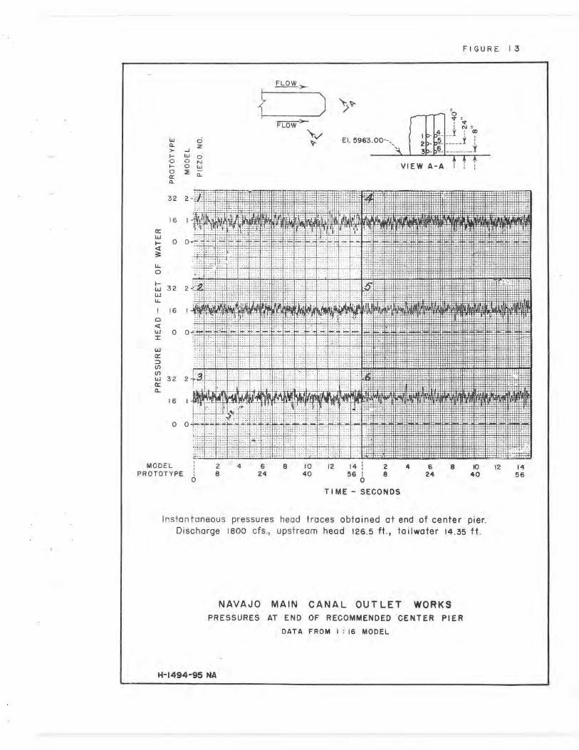
provided on the downstream end of the wall to prevent flow from clinging to the surface and causing adverse pressure conditions. Pressure cell traces obtained for selected positions on the cham-fer showed that no adverse conditions existed (Figure 13).
A structural change in the roof of the prototype basin was nec-essitated by the shorter center wall. With the initial design, the center wall was utilized as a supporting member for a flat roof. With the wall shortened, the increased span required an arched roof.
Tunnel Transition
Flow conditions in the square-to-horseshoe transition just up-stream of the tunnel were unsatisfactory. The transition con-tained intersection lines which extended from the top corners at the upstream end to the midheight of the conduit at the downstream end (Figure 9). The flow near the water surface was restricted by the relatively abrupt transitioning to the extent that the air passage in the crown of the transition was nearly blocked off. The use of the arched roof over the basin made possible a more gradual transition which provided a smoother passage and more satisfactory flow conditions (Figure 18).
Pressures on Gate Chamber Walls Near Seals
Pressure data were obtained on the gate chamber walls just upstream from the gate seals (Figure 8) to study possibilities for venting or relieving seal actuating pressures that might overextend the portions of the seals that become exposed as the gates are raised. The data were obtained at a discharge of 2,120 cfs and show that locations near the floor close to the seals will be subjected to significantly lower pressures than surrounding areas whenever ap-preciable flows are occurring through the gates.
Gate Chamber Invert Modifications
To prevent flow separation and possible cavitation pressures at the point of intersection of the horizontal invert of the gate chamber and the 150 chutes, the slope was extended upstream from the gates into the high-pressure region. To determine the optimum position and shape for the intersecting point, two piezometer-equipped 12-inch-high (3/4-inch model) false floor sections were utilized. In one section the change from the level floor of the gate chamber to the 15° slope of the chute occurred abruptly (Figure 14A). In the other section, the horizontal and sloping sections were connected by a 16-foot radius curve (12-inch model) (Figure 14B). By placing special shims under the sections, the sections and hence the point of intersection, were moved upward and upstream in increments (Figure 14A). Each shim was 4 inches
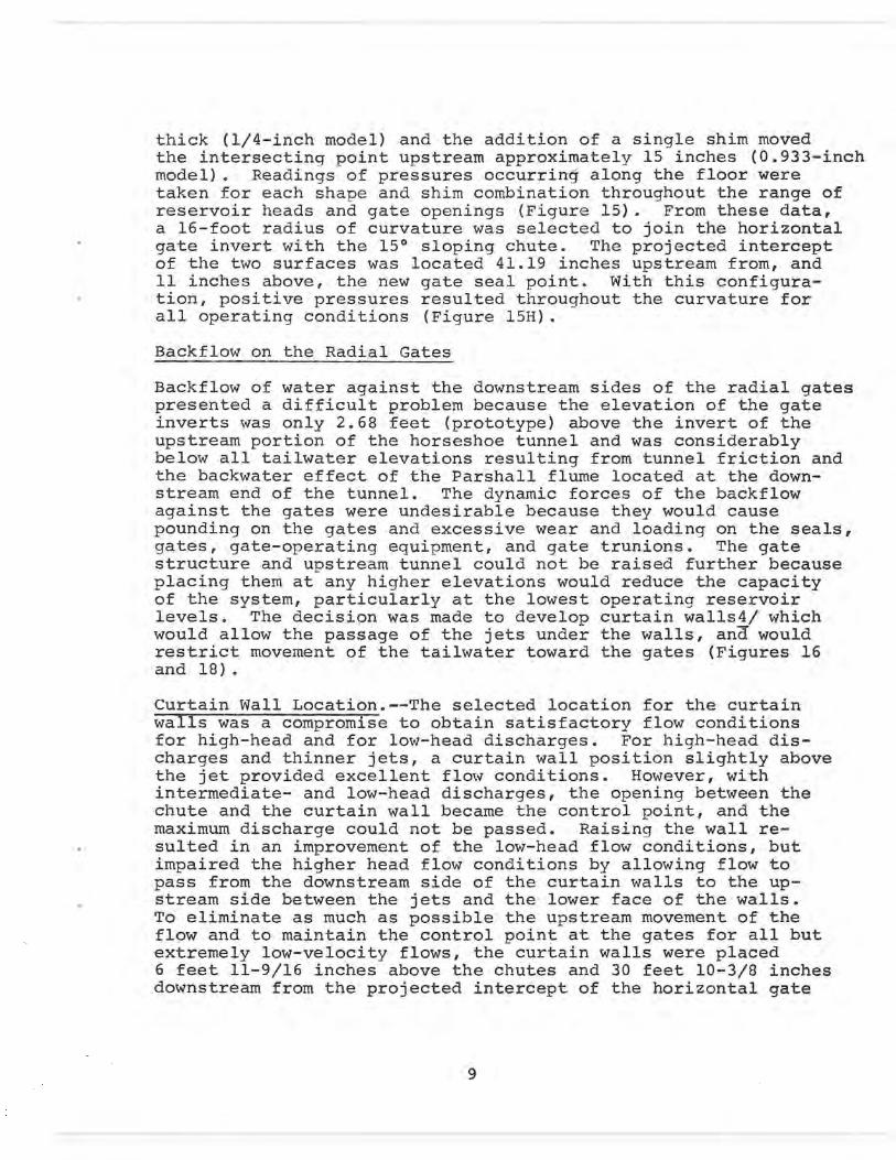
thick (1/4-inch model) and the addition of a single shim moved the intersecting point upstream approximately 15 inches (0.933-inch model). Readings of pressures occurring along the floor were taken for each shape and shim combination throughout the range of reservoir heads and gate openings (Figure 15). From these data, a 16-foot radius of curvature was selected to join the horizontal gate invert with the 15° sloping chute. The projected intercept of the two surfaces was located 41.19 inches upstream from, and 11 inches above, the new gate seal point. With this configura- tion, positive pressures resulted throughout the curvature for all operating conditions (Figure 15H).
Backflow on the Radial Gates
Backflow of water against the downstream sides of the radial gates presented a difficult problem because the elevation of the gate inverts was only 2.68 feet (prototype) above the invert of the upstream portion of the horseshoe tunnel and was considerably below all tailwater elevations resulting from tunnel friction and the backwater effect of the Parshall flume located at the down-stream end of the tunnel. The dynamic forces of the backflow against the gates were undesirable because they would cause pounding on the gates and excessive wear and loading on the seals, gates, gate-operating equipment, and gate trunions. The gate structure and upstream tunnel could not be raised further because placing them at any higher elevations would reduce the capacity of the system, particularly at the lowest operating reservoir levels. The decision was made to develop curtain walls4/ which would allow the passage of the jets under the walls, and would restrict movement of the tailwater toward the gates (Figures 16 and 18) .
Curtain Wall Location.--The selected location for the curtain walls was a compromise to obtain satisfactory flow conditions for high-head and for low-head discharges. For high-head dis-charges and thinner jets, a curtain wall position slightly above the jet provided excellent flow conditions. However, with intermediate- and low-head discharges, the opening between the chute and the curtain wall became the control point, and the maximum discharge could not be passed. Raising the wall re-sulted in an improvement of the low-head flow conditions, but impaired the higher head flow conditions by allowing flow to pass from the downstream side of the curtain walls to the up-stream side between the jets and the lower face of the walls. To eliminate as much as possible the upstream movement of the flow and to maintain the control point at the gates for all but extremely low-velocity flows, the curtain walls were placed 6 feet 11-9/16 inches above the chutes and 30 feet 10-3/8 inches downstream from the projected intercept of the horizontal gate

chamber inverts and the 151 chutes (Figure 16). The top of the walls was placed at elevation 5987.55 so that overtopping could occur in order that the outlet works could pass 1,800 cfs at a 15-foot reservoir head (Figure 19A). With this configuration and high-head flows, occasional overtopping of the wall in the upstream direction results; however, the magnitude is slight and the flow does not reach the gates (Figure 18).
Shape of the Bottom of the Curtain Walls.--Initially, the bottom of the curtain wall was horizontal with sharp 90° corners at the upstream and downstream wall faces. A low-pressure area existed immediately downstream from the upstream corner of the wall along the horizontal bottom. By means of dyes, flow from the downstream side of the wall was observed to move around the downstream cor-ner of the wall in an upstream direction into the low-pressure area. The momentum was sufficient to carry the flow past the up-stream face of the wall where it impinged on the jets from the gates. To improve the flow conditions, the bottom of the wall was cut at a 15° angle to parallel the sloping chute. This greatly reduced the amount of flow moving from the downstream side to the upstream side of the wall, and hence the amount of water impinging on the jets from the gates. Instantaneous pres-sures obtained at selected points along the bottom were found to rapidly fluctuate and to reach one-half atmosphere below at-mospheric pressure. In an attempt to eliminate the rapidly fluc-tuating pressures, a 195°, 6-inch-radius lip was placed on the downstream lower side of the wall to act as a spoiler (Figure 16). Instantaneous pressure traces revealed that a stabilizing effect results from this modification. The 6-inch-radius lip was then replaced by a larger 1950, 12-inch-radius lip. Instantaneous pressure traces still showed rapidly fluctuating pressures (Fig-ure 20); however, the lowest pressures were sufficiently high to prevent cavitation and insuing damage.
Chute Blocks
Chute blocks were used in the initial design (Figure 2); however, they were ineffective. Even with maximum reservoir heads the jets seldom penetrated to the position of the chute blocks at the down-stream end of the parabolic chute. The chute blocks used with the subsequent parabolic chute design also were ineffective. With the 15° sloping chutes, chute blocks were undesirable because they helped break up the high-velocity jets with the result that greater depths of water occurred in the upstream portion of the basin. This caused greater backflow against the gates for most operating conditions and overtopping of the curtain walls from downstream when maximum flows were passed at high reservoir elevations. For these reasons, chute blocks were not used in the final design (Figure 16).
10

Baffle Piers
The initial stilling basin contained four large baffle piers at the downstream end of the basin (Figure 2). The jump formed ap-proximately 75 to 100 feet upstream from the baffles; thus, the baffle piers were completely ineffective. Much better results were obtained with baffle piers placed nearer the upstream end of the basin. For initial pressure evaluation, the baffle piers were located 16 feet downstream from the end of the chutes. In-stantaneous pressure traces showed that severe cavitation pres-sures existed on the baffle piers at this location. The piers were moved downstream to a point 32 feet from the end of the chute, and additional instantaneous pressures obtained revealed an improvement in the pressures; however, they were still suf-ficiently low to cause damage. Further movement of the baffle piers to 48 feet downstream from the end of the chute eliminated the severe subatmospheric pressures on the baffle piers while still maintaining most of their effectiveness (Figures 19B and 21). The baffle piers conform in shape to those specified in Engineering Monograph No. 25 1/; however, they are considerably larger. The piers have sharp corners which increase the turbu-lence generating capacity and improve the basin performance.
Single-gate operation at high heads and discharges above 900 cfs indicated that undesirable low pressures will be generated on the baffle piers and prolonged operation in this manner should be avoided.
Underpass Wave Suppressor
An underpass wave suppressor (Figure 16) was found necessary to provide a smooth water surface in the downstream tunnel. The wave heights in the tunnel with the recommended stilling basin but without the suppressor were 3.2 feet maximum, measured from trough to crest. By adding the recommended suppressor, the wave heights were reduced to approximately 0.8 foot (Figure 22). The under-surface of the recommended wave suppressor was slotted to reduce the size of surges and also reduce the differential head acting on the suppressor.
Gate Calibration
The two radial gates were calibrated for single- and double-gate operation for piezometric heads in the approach tunnel (Station 4+18.50) ranging from 14 to 130 feet (Figures 23 and 24). Dis-charge curves were prepared in increments of 5 percent from 0 to 30 percent gate opening and in increments of 20 percent from 40 percent to full open. For the calibration the gates were
11

set to the desired opening, as measured vertically from the bottom of the gates to the surfaces of the chutes. A vernier caliper maintained in the vertical position with the aid of a bubble level was used to set the model gate openings. The upstream head on the radial gate was adjusted by a gate valve on the upstream end of the model inlet pipe. The tailwater was adjusted to provide depths specified by the tailwater curve for the 17-foot 6-inch horseshoe tunnel with backwater from the Parshall flume and based on Manning's "n" of 0.013 (Figure 7, Curve A) .
Operating Restrictions
All normal regulation of the flow in the prototype will be accom-plished with the radial gates. If, however, control of the flow is attempted by the fixed-wheel gates located upstream of the radial gates, the control should be restricted to discharges at low reservoir heads. Higher head operation may cause severely subatmospheric pressure conditions along the 16-foot-radius curve from the horizontal invert of the gate chamber to the 15° sloping chute.
Balanced gate operation (equal gate openings) will provide the best basin performance and should be used for high-velocity, high-discharge releases. Single-gate operation at high reservoir heads and discharges above 900 cfs will result in undesirable pressures on the baffle piers and should be avoided for prolonged operation.
12
CONCLUSIONS
1. The performance of the basin, as initially conceived, was unsatisfactory. Large, objectionable surges occurred in the downstream portion of the basin and in the horseshoe tunnel (Figure 9).
2. The initial center dividing wall, extending the full length of the basin to the start of the horseshoe transition, caused lateral differential heads as the flow reached the downstream end of the basin, and a swinging motion was imparted to the flow in the tunnel.
3. The initial parabolic chute did not provide a stable hydrau-lic jump (Figure 9). Upstream and downstream movement of the toe of the jump caused heavy surging in the stilling basin, and backflow struck the downstream side of the radial gates.
4. Raising the invert of the gate chamber from elevation 5'?69 to elevation 5975, and using a longer parabolic chute did not elim-inate the unstable jump nor the backflow onto the radial gates.
5. Elimination of the chutes by using 12-foot vertical drops extending to the basin floor just downstream from the radial gates produced very unstable and undesirable flow conditions (Figure 11).
6. The use of 150 sloping chutes eliminated most of the heavy surging that was characteristic of the flow with either the original or the longer length of parabolic chute (Figure 18). Although reduced in intensity, backflow still struck the radial gates.
7. The use of a 16-foot radius of curvature to join the gate chamber horizontal invert to the 150 sloping chutes, and start-ing the curvature in the high-pressure region upstream from the radial gates, eliminated cavitation pressures and provided a well-directed jet along the chute (Figures 14 and 15).
8. Four baffle piers located 48 feet downstream from the chutes effectively turned a portion of the flow upward to aid in form-ing the jump (Figure 19B). The pressures acting on the baffle Piers were sufficiently high to prevent cavitation damage under normal operating conditions (Figure 21). However, single-gate operation at high heads with discharges above 900 cfs will re-sult in cavitation pressures and should be avoided in the prototype.
13
9. Vertical curtain walls placed a short distance downstream from the gates, with the wall inverts far enough above the chute to allow passage of the jets, prevented backflow from striking the downstream sides of the radial gates (Figure 18).
10. Within design discharge requirements and at all gate open-ings, the jets, from under the gates, resulting with reservoir heads between 126.5 and 36 feet, sweep the backwater free of the gates and the gates operate under free discharge conditions (Figure 18).
11. With reservoir heads below 36 feet, the flows from the gates become intermittently and then completely submerged (Figure 19A).
12. To pass the maximum discharge at the minimum reservoir head, the curtain walls must be overtopped (Figure 19A). A higher head loss than that calculated for the upstream conduit, transi-tions, and gate chamber will result in a discharge lower than 1,800 cfs at the minimum reservoir head. This occurrence is not expected in the prototype.
13. An underpass wave suppressor with a solid upstream headwall and a slotted horizontal surface produced the nearly smooth, water surface necessary in the downstream tunnel (Figures 18 and 22) .
14. Balanced gate operation will provide the best basin per-formance and should be used .for high-velocity, high-discharge releases.
15. Regulation of the flow by the fixed-wheel gates located upstream from the radial gates should be restricted to low res-ervoir discharges or to emergency situations because severe subatmospheric pressure conditions may occur along the curved invert between the gate chambers and the 15° sloping chutes, causing cavitation.
M

BIBLIOGRAPHY
1. "Hydraulic Design of Stilling Basins and Energy Dissipators," Engineering Monograph No. 25, U.S. Department of the Interior, Bureau of Reclamation, 1964
2. Bakhmetaff, B. A., and Feodorof.f_, N. V., "The Flow Through Slits," Proc. Fourth Midwestern Conference on Fluid Mechanics, 1955
3. Colgate, D., "Hydraulic 14odel Studies of Tantangara Dam Outlet Works--Snowy Mountains Hydro-Electric Authority, Australia," Report No. Hyd-441, September 1958
4. Wagner, W. E., "Hydraulic Model Studies of Howard Prairie Dam Outlet Works--Oregon," Report No. Hyd-436, April 1957
15

108.10' I D 0
36.56 -
FIGURE I
KEY MAP
NOTE' BUREAU OF LAND MANAGEMENT TOWNSHIP
AND RANGE LINES. NEW MEXICO STATE COORDINATE SYSTEM- WEST ZONE.
Ha O Ir 3 4-Vt 6 X
SCALE OF MILES
~L
EXPLANATION
PRIMARY ROADS
SECONDARY ROADS
NAVAJO MAIN CANAL OUTLET WORKS
LOCATION MAP

FIGURE 2
ry 7-1 AL j
L o ---------- -- -------- 3" c=— ALT
SEC T IONA L PL AN
E I. 6100.00
Top conservation s1—,: WN E1. IIo' -------
N11,11 W,s EI.6067.0 --------
—,.00
M, ope,oti,g ------- El.—o ----------- 4 ,,
El. 5989.go----, —El ~III '',l Wp• 2120 ~ '02 1'917
R.dl.I g.in
g' -G ---------
EO.
2 El 5970,9o,,,, ,f —,diodes El 5969,00-
E E I I G G I 59G6.00 "I
-2--o 1—o F—d
,.h.
e~l 9.t,I Gt oI
loo, ----- ------------------- ---------------------- ----------- ----------- ioo'-o --------- ------------ - ------------ 3D'-G 28-6 -------- 27'- 91 --------------------- - , - -------------------------
SEC T ION A — A
NAVAJOMAIN CANAL OUTLET WORKS INITIAL STILLING BASIN DESIGN

tram stilling pool to horseshoe t,,n,i ------------ mI----9egi, tunnel
s. 1062 599-7,,
C,,t,, of
--- - --
-- 67-0 ----------- -- - C,nfor Imo of .clio'
point inside fu- - I
22 _p ----------
1. -0
—Y
El. I—
----------- A
-------- --- 3 -----------
S E C T4 0 N A A
FIGURE
EIL 598].00
2-9-0.120 F-1 Wheel got es not h_
S to. 4 36.5
- --------- 2a-d ---------- ----- -------- ------ 1. , - -------------
—El —W
oo Dooil A -4- ILGot' pm
So'
61o"
R,d,,l tes
-Origin of -rdi~mt,,
slo o0oli 8
- - -L ------- ------------
ELEVATION
j
,
- d to I pin
DETAIL A
f-1 to 4- Din
DETAIL 8
NAVAJO MAIN CANAL OUTLET WORKS MODIFIED BASIN WITH RAISED UPSTREAM CONDUIT, PARABOLIC CHUTES, AND SHORTENED CENTER PIER

PL N TOP E M ho 11101TIL DETAIL 0
i.mam,
"GURF 4
--Transition, Rectangle to Square
- -- ,-Transition Square to Horse-shoe
Sid. pipe 12 Sid. to ,s - - - - - - 1-0 - - - - - — - - - - - - - - - - e'-e - - - - - - - - - - - - - - - - - - - 14s I.D. Morse-shoe conduit
f -T-4-7 n111
Plastic woll
32, I.D. pips-Z ------ - — - - - - - - - - - - - - - - 6-3 - - - - - - - - - - - - - '_'T r.p,tion. 13q RDUndin Spcs. @
to-Ty r9 Rectangle PLAN
P LAN sHo—
PROFILE A. INITIAL STILLING BASIN DESIGN
DETAIL A
,-T- Got, pins -Cnomi c,ov,o transit. It
'0'igm of 316-Y _Mdn.ts
•A-
------------- ---------
PROFILE
C. MODIFIED BASIN WITH RAISED UPSTREAM CONDUIT, PARABOLIC CHUTES, AND SHORTENED CENTER PIER.
— -------------- 5 q -------------- -----
Curtain wails, fDetofl A
So' "I S PLAN
-$1a.5-32.67 C,nk,l crown transition--
St.. 5*0].91---ti q Got. phs. EL 596].54] Wave suppressor---_ W's. - No 'fs"
El. 5994.67
Curtain ,E1.5975- Detail
Z ,-E1. 5963.00
-3 --------- - P. 1. of horn. floor ogle 15' chute.
PROFILE
D. RECOMMENDED STILLING BASIN
NAVAJO MAIN CANAL OUTLET WORKS MODEL DRAWINGS
I : 16 SCALE
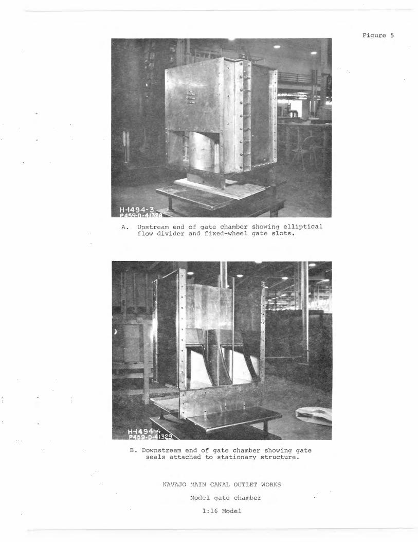
Figure 5
A. Upstream end of gate chamber showing elliptical flow divider and fixed-wheel gate slots.
B. Downstream end of gate chamber showing gate seals attached to stationary structure.
NAVAJO MAIN CANAL OUTLET WORKS
Model gate chamber
1:16 Model
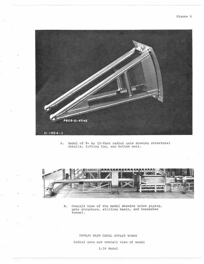
Figure 6
A. Model of 9- by 12-foot radial gate showing structural details, lifting lug, and bottom seal.
B. Overall view of the model showing inlet piping, gate structure, stilling basin, and horseshoe tunnel.
NAVAJO MAIN CANAL OUTLET WORKS
Radial gate and overall view of model
1:16 Model

FI GURE 7
16.0
14,0
1 2.0
W W 10.0
J W Z Z D
8.0 Z
x CL W 0
6.0 3 O J LL-
4.0
2.0
0 500 1000 1500 2000
DISCHARGE-CFS
NAVAJO MAIN CANAL OUTLET WORKS
TAILWATER CURVES
I
i8' Dia. Circular tunnel.----_,,
Curve A. IT`-6" Horseshoe tunnel with backwater from Parshall flume.-----
_
J
~ -'-- ---17'-6" Horseshoe tunnel without backwater
from Parshall flume.
0.0 1 1

FIGURE 8
DISCHARGE 2120 CFS UPSTREAM GATE
MEAD OPENING Z 2 ~O \ • 132.5 FT. 13% p _ 3 4 , AGATE PIN, ■ 88.0 FT. 18% -N I _-i Z------
O 50.0 FT. 25% - o N =' -- 5 T I N
❑ 21.0 FT. 74% ~ 6 X2 = 530Y
(p N N -
140
120
100
W H Q 3 LL Q
80 w w LL I 0 Q w z 60 w
w
IL
40
20
00 1 2 3 4 5 6
PIEZOMETER NUMBER
NAVAJO MAIN CANAL OUTLET WORKS
PRESSURES ON WALL UPSTREAM OF GATE SEALS
DATA FROM 116 MODEL

A. Note large splash over jump.
B. Note large wave followed by trough.
C. Note large surge wave.
Figure 9
NAVAJO MAIN CANAL OUTLET WORKS
Unstable flow in initial stilling basin.. Discharge 2,120 cfs, head 132.5 feet, tailwater 15.75 feet
1:16 Model

Figure 10
A. Large baffle piers held jump in basin.
B. Jump swept from basin with baffle piers removed.
NAVAJO MAIN CANAL OUTLET WORKS
Unsatisfactory flow with gate invert level with basin floor. Discharge 2,120 cf_s, head 132.5 feet
1;16 Model

Figure 11
A. Jet directed downward tailwater 1.60 feet below normal.
B. Jet horizontal tailwater approach- ing. normal.
C. Jet directed upward tailwater normal.
D. One jet directed upward, and the other downward. Gates equally opened, tailwater normal.
NAVAJO MAIN CANAL OUTLET WORKS
Unstable flow with 12-foot vertical step downstream from gates. Discharge 1,800 cfs, head 89 feet, gate opening 17 percent.
1:16 Model —
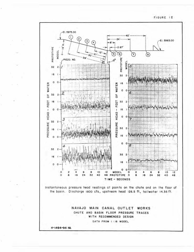
FIGURE 12
-EI. 5975.00 n I- --------------40'
i w io i a J H W 0 0 30`2j
w /PIEZO. NO. 39 _
a I/
17 32 2
16 1
cr 0 0 w
Q 3 LL 32 2 O
W 16 I w LL
0 0
Q W 2 w 32 2
~ 16 I w cr a O 0
32 2
16 1
0 0— 16 1_
- ~-
ur
0 2 4 6 8 10 12 MODE L 0 2 4 6 8 10 12 O 8 16 24 32 40 48 PROTOTYPE 0 e 16 24 32 40 48
TIME -SECONDS
Instantaneous pressure head readings at points on the chute and on the floor of the basin. Discharge 1800 cfs., upstream head 126.5 ft., toilwater 14.35 ft.
NAVAJO MAIN CANAL OUTLET WORKS
CHUTE AND BASIN FLOOR PRESSURE TRACES WITH RECOMMENDED DESIGN
DATA FROM 1:16 MODEL
H-1494-94 M
16 Cr w H 0 0 Q 3 LL 0
w 32 2 w U- 1 16 1 O Q W 0 O a
w tr rn N w 3'2 2 rr a L
FIGURE 13
w o a z } J F- W p O ~ N
0 2 a
32 2
FLOW >
_ 0 v-
FLOW A
- 4 ro
E1. 596-3.00-
-,F23 _ 5_
- 6 --------Y
VIEW A-A 1 I
MODEL 2 4 6 8 10 12 14 ; 2 4 6 8 10 12 14 PROTOTYPE 0 8 24 40 56 O 8 24 40 56
TIME - SECONDS
Instantaneous pressures head traces obtained at end of center pier. Discharge 1800 cfs., upstream head 126.5 ft., tailwater 14.35 ft.
NAVAJO MAIN CANAL OUTLET WORKS PRESSURES AT END OF RECOMMENDED CENTER PIER
DATA FROM 1:16 MODEL
H-1494-95 NA

Figure 14
A. Section with abrupt change from horizontal gate chamber invert to 15° slope. Shims were used to raise sections and move.point of intersection upstream.
B. Section with 16-foot-radius curve connecting gate chamber invert and 15° slope.
NAVAJO MAIN CANAL OUTLET WORKS
Sections used in determining position and shape of inter-section of gate chamber floor and 15° sloping chutes.
1:16 Model

2_6"__y "3 _
I-4 1-4___
V h h
I 2 3
A. PIEZOMETER LOCATIONS WITH ABRUPT 4 5
D. PIEZOMETER LOCATIONS WITH 16 FOOT G. PIEZOMETER LOCATIONS IN CHANGE IN SLOPE RADIUS CHANGE IN SLOPE RECOMMENDED DESIGN
1.DD
0.9 1
1.QO
0.9
I DO
0.9
0.8 0.8
0.7
¢ 0.6 ow a¢
0.5 x rc
I ¢
ow ax
i rc
0.8
0.7
0.6
0.5
I 0.7
¢ 0.6 ow as i 0.5
rc
I
2 -
wy ~w 0.4
rc a 0.3 a¢
2 w~ ~N
¢ a¢
0.4
0.3
p
3
wN Nm 0.4
¢ ¢ 0.3 a¢
3
4 0.2
~o z ow
0.2 .0 z> 0.2 - - - -
0.1 4 5 a
0.1 4
oN 5
0.0 6
0.0 0.0 --
-0.1
3
-0.1 6
-0.1 - - -.
-0 3 0 20 40 60 80 100 -03 0 20 40 60 80 !00 -O3 0 20 40 60 80 100
GATE OPENING - PERCENT GATE OPENING - PERCENT GATE OPENING - PERCENT
B.
1.W
0.9
NO SHIMS UNDER TEST SECTION E.
1.00
0.9
NO SHIMS UNDER TEST SECTION H. RECOMMENDED DESIGN
0.8 Q
ow 0.7 qx w
yr O.6
jrn
2 _
Q
ai w
w rcy
0.8
0.7
0.6 2
qW w¢ 0.5 ¢a
Nw w¢ wa ¢
0.5
3 a ¢
0.4 F D
5
a 0.4
°'3
i
a °'3 NAVAJO 5 MAIN CANAL OUTLET WORKS 0.2 ¢ 0.2 FLOOR PRESSURES ALONG JUNCTION
0.1 3
0,1 OF GATE CHAMBER INVERT
s AND 15 DEGREE SLOPING CHUTES
0O 0 20 40 60 80 IQO °° 0 20 40 60. BO 100 DATA FROM 116 MODEL GATE OPENING - PERCENT GATE OPENING - PERCENT
C. TWO SHIMS UNDER TEST SECTION F. TWO SHIMS UNDER TEST SECTION

----------------------------------------------------- 89-0 -----------------------------
5 Spaces @ 1'4" equals 61-8"
Curtain wall
H< ----------------------- 46'— 4811--------------------- ~ --
rt Gate pjn_-----~--StQ. 5+32.67 S to. 5 + 07.91
Z-
-El. 5987.55
---------------
-----Curtain wall
,-Detail A E1.597.5.00 1J, , -
Detail B
0
Y
------------------------ 48'-0 - ---------- - ----------- —i
PLAN
E I. 5994.67
4" 444
W10 v U Water surface suppressor, 1800 c.fs
-----------
i-------------------------- 52'_0 --------
PI. of horizontal floor and 150 chute.
--- 1-0
0"
7—N 4"R- 12" R.
P T.
DETAIL A
El. 5963.00 00 I
T,~ 5LB"
ELEVATION
NAVAJO MAIN CANAL OUTLET WORKS RECOMMENDED STILLING BASIN
FROM I : 16 MODEL
C

O
N
I
I
I
ixed wheel gate slots
9.. p NOTE
o. .o All dimen sions prototype
o • " o.•a
o • o • ----- .o-. ----Tapered roof line
---------~
I u n
i i I
i
FLOW
I
I I I I
I I
I
I ~
• o - o o. o .Q .p - o p' a I o 0
~I
FINAL TESTS —' PROTOTYPE DESIGN `TI' MODEL AS CONSTRUCTED
54 5~
NAVAJO MAIN CANAL OUTLET WORKS
DEVIATIONS BETWEEN MODEL AND PROTYPE ROOF LINES OF GATE CHAMBER
0
m
mi

:v I F.
4040M M
Figure 18
A. Double-gate operation. Discharge 1,800 cfs, head 126.5 feet, tailwater 14.35 feet. Note smooth water surface in tunnel.
B. Single-gate operation. Discharge 900 cfs, head 126.5 feet, tailwater 9.55 feet. Note smooth water surface in tunnel.
NAVAJO MAIN CANAL OUTLET WORKS
Flow in recommended stilling basin
1:16 Model

Figure 19
A. Curtain wall being overtopped to pass 1,800 cfs with an upstream head of 15 feet. Tailwater 14.35 feet.
B. Baffle piers helped in turning the flow upward. Discharge 1,800 cfs, head 126.5 feet, tailwater 14.35 feet.
NAVAJO MAIN CANAL OUTLET WORKS
Flow with minimum head, and baffle pier effectiveness - Recommended Design
1:16 Model

FIGURE 20
IEZO. NO.
1
32 2-
16 1- .:.
0 0
-1 6 _1
32 2
16 1
0 0 cr w H -16 -I a 3
0 F 32 2
w w 16 I LL 1 0 0 0 a w -16 -1 S
w cr
to Cf) 32 2 w
a 16 1
0 0
-16 -1
32 2-1
16 IJ I 1 11 I ~ it
1 I
-16 -I
- - , I
w ,a UPSTREAM HEAD 126.5 FEET UPSTREAM HEAD 110 FEET ~ w 0 0 o o o 2 a
UPSTREAM HEAD 92 FEET
f w—1 +
3 4 5
CURTAIN WALL PIEZOMETER LOCATIONS
NAVAJO MAIN CANAL OUTLET WORKS INSTANTANEOUS PRESSURES ON LOWER FACE OF CURTAIN WALL
RECOMMENDED DESIGN
DATA FROM I:16 MODEL
H-1494-96 NA

FIGURE 21
w ~PIEZO. NO a ~ r w H 0 0 o a
MEN Elni
• •~
:::~
~o ®Em
199 m OZONE
E M® Si
N E-11~
MEN X991100
:Mi"m.. _
rs Ell Ell
En
is es:9,:a:~•a::»::..,~
EVA
• ~':.€1>~~"-'ice==~' ...zero=~~°^iae°.m~"—~'!
as e fff.I's
a.
NAVAJO MAIN CANAL OUTLET WORKS BAFFLE PIER PRESSURES — RECOMMENDED DESIGN
DATA FROM I:I6 MODEL
I H-1494-97 NA i
•

FIGURE 22
• - .... .. ... ... ., ......... EMNI .` liilIN.. lll.. li ':liiilli•:111's llillllllllillalll:'illlllliilll~lelliilii 'Ili j ...
1 loom IYI° i Illillll'1~1==~ ,g: 11311111111111....... ~ 1~ '=.! 111~IPIII _€~'1=.i iilll 6.:'R. S i ...^. i e:L'1 ':.
IMMENSE~ i slsil^= il...11 i.~'s•;11..s^ ?. i~,11 ,lii ilkI11,111 il~ili 33 ; • ~ = i ~
'!j"'.i=: • J la's[; ial'ei .«Is ivai ~'ii !iil............... ' i'iilfieaisa' ;1es,,ls' a EEEa:! ~'~!°iilg ",~..~,.....i..as.:: ..I~...i^.11l.lia:.::a ~~~~yy {{~ x lea, ai:e• „ili!ii a u aluljil^li! lu ..... i~'~~1Y
•
yy~l1 S NI EL Ia-113li~ ^^•.^:: ' 1 6.:il:i.;iL,7~ 1i . x iY JUN li :,1 I I Ililllli L~•0i: lai:iieil,':iel'i l.'l l`::C::a:i::16:C1!'llil"7 iieil7Llli'iCll I g •a a s1 .: s ssat~ ^es:a:r:a:::i:: ;...".°•i^::as:::r•s.isri• :!
Llls: 1i'retie:ai!'s'slle `s::i's;;e':'s's's':ei'seis:eiiM:ise;.:si11! Mill IS
. 1.i• i lllllli:i7s> ill " pull llllsee2 eEeie;i3l7:i:'ii13s . p •:77:.:..::.....
~. e i sl ~ a :iislll U. :':l .111111111111111.11 ...:ii's?° i3aii1111=.Ils X11 .'17......
1= ..
a : '=.lilelllillillll.... .....:11ii111111111N li ii111 !S ~i:.•Rai i 1 :Ili= :751C'.1 ! sllll:.iil.11lll.l...:....l.. 11.1 MR 1 11111111111111€111=€11€1113 llllllllll lE
1. 1 ail iii 11!1°1 i .eii..ill 'iiiii iiiia7limEA.i j !dell=l• eililliil=ie ;lB1;E1iitisp•: •1 Ali
7 1'T l 'ii i I ~9'
~~l.1111~1133111111i1iii13111i3: ';liilllll=.i1~ LITNE
i11111111SIIIi~l~ii::lla1161111i1~
Ise?EEe:s's'sl':s:ll l lilliP, 111
' l:~Elliii
A A
il9isil'
L .
~111111611 1.~'
~7f'pp~~'~~giggqlRyyY3~ss~~ssazaz Rs
IRA[r!9!g!!!i~'s.''ea;p~
m11131~II~III11i111==1Us~1
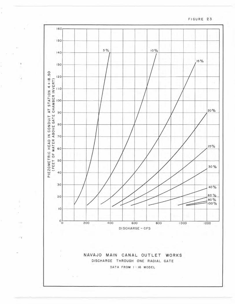
FIGURE 23
160
150
140 5% 10%
15% 130
O U)
120 ao ^ — F— t It w > 110 Z Z O
Er
Q m 100
cn Q
~ = 20% Q 0 90 w
— F- <
0 " z 80 ,,~ O> 0 O m Q 70
0 X Q w
= 3 60-
0 w 0~ O W 50 H
LU
0 LL 30% N w 40 d
30 40
20 60% 80 100%
10
0 0 200 400 600 800 1000 1200
DISCHARGE — CFS
NAVAJO MAIN CANAL OUTLET WORKS DISCHARGE THROUGH ONE RADIAL GATE
DATA FROM 1:16 MODEL

130 10% 501/0/l
120 15%
110 O
0 F + 100
W >
Z Z O 90 I- W
m F-- U) Q 80
a W H F 70 a 20%
O O Z W 0 > 60 00
CL Z Q -
X Q LL) 50 25% W
Q
0 LL 40 w 0 30% H W W
Ld O LL 40 % 40% N W a -60%
20 80 100%
10
1 F1 - 00 200 400 600 800 1000 1200 1400 1600 1800 2000 2200
DISCHARGE - CFS
NAVAJO MAIN CANAL OUTLET WORKS
DISCHARGE THROUGH TWO EQUALLY OPENED RADIAL GATES
DATA FROM 1 16 MODEL
