hydraulic cable cutting safety heads...13 - head fixing pin 1 3 2 4 8 10 11 9 1 3 11 10 5 7 6...
TRANSCRIPT

1
HYDRAULIC CABLE
CUTTING SAFETY HEADS
TC050Y-KV TC065Y-SC-KV
TC085Y-KV TC096Y-KV TC120Y-KV
ENGLISH OPERATION AND MAINTENANCE MANUAL
17
M 2
19
U

2
TC065Y-SC-KVmax. cutting diameter
2-9/16”
1. DESCRIPTION OF THE MAIN COMPONENTS
1 - GROUNDING SOCKET 7 - UPPER BLADE
2 - RIGHT BLADE 8 - LEFT BLADE
3 - GROUNDING KNOB 9 - GRIP
4 - HANDLE (to be fitted) 10 - HANGING POINTS FOR SUPPORT STRAP
5 - HEAD LATCH 11 - MALE INSULATED QUICK COUPLER
6 - LOWER BLADE 12 - HANDLE
13 - HEAD FIXING PIN
1
3
2
4
8
10
11
9
1
3
11
10
5
7
6
TC050Y-KVmax. cutting diameter
2”

3
TC120Y-KVmax. cutting diameter
4-3/4”
TC085Y-KVmax. cutting diameter
3-3/8”
TC096Y-KVmax. cutting diameter
3-3/4”
1
8
3
2
10
12
111
13
12
11
10 6 3
5
6
7
1
4
10
11
3
7
4
Before using these safety heads, carefully read the instructions in this manual.
Keep hands clear of cutting blades.
Always wear safety glasses and gloves when operating these safety heads.
WARNING SYMBOLS
Do not cut Steel.
Do not attempt to cut Steel ropes or Steel reinforced cables (ACSR), the heads
are designed for cutting Copper or Aluminum cable.
Cutting operations must be strictly in accordance with the
safety and working procedures established by the responsi-
ble power utility.
((
((
((
((
5
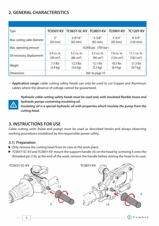
2. GENERAL CHARACTERISTICS
Type TC050Y-KV TC065Y-SC-KV TC085Y-KV TC096Y-KV TC120Y-KV
Max. cutting cable diameter2”
(50 mm)
2-9/16”
(65 mm)
3-3/8”
(85 mm)
3-3/4”
(95 mm)
4-3/4”
(120 mm)
Max. operating pressure 10,000 psi (700 bar )
Oil necessary, displacement2.4 cu. in.
(39 cm3)
5.2 cu. in.
(86 cm3)
5.5 cu. in.
(90 cm3)
7.6 cu. in.
(124 cm3)
11.1 cu. in.
(182 cm3)
Weight7.5 lbs
(3.4 kg)
12.3 lbs
(5.6 kg)
12.1 lbs
(5.5 kg)
18.5 lbs
(8.4 kg)
21.3 lbs
(9.7 kg)
Dimensions Ref. to page 10
– Application range: cable cutting safety heads can only be used to cut Copper and Aluminum
cables where the absence of voltage cannot be guaranteed.
Hydraulic cable cutting safety heads must be used only with insulated flexible hoses and
hydraulic pumps containing insulating oil.
Insulating oil is a special hydraulic oil with properties which insulate the pump from the
cutting head.
3. INSTRUCTIONS FOR USE Cable cutting units (head and pump) must be used as described herein and always observing
working procedures estabilised by the responsible power utility.
3.1) Preparation
Only remove the cutting head from its case at the work place.
TC065Y-SC-KV and TC085Y-KV: mount the support handle (4) on the head by screwing it onto the
threaded pin (14); at the end of the work, remove the handle before storing the head in its case.
TC065Y-SC-KV TC085Y-KV
14
14
4
4
6
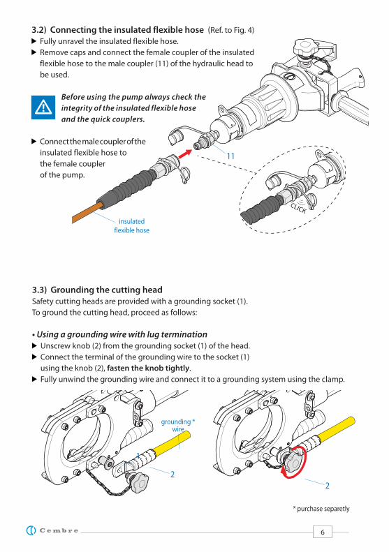
3.2) Connecting the insulated flexible hose (Ref. to Fig. 4)
Fully unravel the insulated flexible hose.
Remove caps and connect the female coupler of the insulated
flexible hose to the male coupler (11) of the hydraulic head to
be used.
Before using the pump always check the
integrity of the insulated flexible hose
and the quick couplers.
Connect the male coupler of the
insulated flexible hose to
the female coupler
of the pump.
CLICK
3.3) Grounding the cutting head
Safety cutting heads are provided with a grounding socket (1).
To ground the cutting head, proceed as follows:
• Using a grounding wire with lug termination
Unscrew knob (2) from the grounding socket (1) of the head.
Connect the terminal of the grounding wire to the socket (1)
using the knob (2), fasten the knob tightly.
Fully unwind the grounding wire and connect it to a grounding system using the clamp.
1
2
2
insulated
flexible hose
11
grounding *wire
* purchase separetly

7
13
5
cable
Once the blades of the cutting head are around the cable to be cut, stabilise the head in position
(e.g. by pressing the cutting head against the ground); when used in the “man-hole” we recommend
the usage of SS-TCY support strap (Ref. to § 6) in order to support the head in the horizotal stable
position.
cable
• Using a grounding wire with ball & socket termination
Unscrew knob (2) from the grounding socket
(1).
Screw the grounding pin (15) tightly into the
socket (1) (1/2”-13 UNC thread).
Fully unwind the grounding wire and connect
it by the clamps to the grounding pin (15) and
to the grounding system using the clamps.
3.4) Positioning the cutting head
The cutting head must be manually positioned
around the cable to be cut based on the diameter
of the cable (Ref. to § 1).
TC065Y-SC-KV and TC096Y-KV: insert the cable
between the blades, at the desired cutting point.
TC050Y-KV and TC085Y-KV: release latch (5) to open the blades.
Insert the cable, close the head and fully secure the latch (5).
Ensure that the head is fully secured: partial closure may damage the head.
TC120Y-KV: Extract the locking pin (13) to open the blades. Insert the cable, close the head and
fully secure the locking pin (13).
Ensure that the head is fully secured: partial closure may damage the head.
Make sure the blades are exactly positioned on the desired cutting point.
1
15 *
2
* p
urc
has
e se
par
atel
y
TC120Y-KV
TC085Y-KV
TC050Y-KV
5

8
3.5) Cutting
Cutting operations strictly follow the safety and working procedures established by the
responsible power utility.
Fully unravel the insulated flexible hose to provide a safe working distance.
Operate the pump to advance the blades and progressively cut the cable.
At the end of the operation open the blades using the oil release control of the pump.
Access the cutting area and remove the cutting head from the cable using the support grip
provided.
3.6) Unintentional cutting of live cable
Following a short circuit, contact the electricity power utility immediately for information.
To access the cutting area and remove the cutting head, strictly follow the safety and working
procedures established by the responsible power utility.
4. STORAGE AND TRANSPORTATION
Each Cembre cable cutting safety head is pre-
cisely constructed and supplied in a robust steel
case (canvas bag for TC050Y-KV) for protection
of individual components from damage and for
transportation to the work place.
Only remove a cable cutting head- from its case
at the work place.
TC065Y-SC-KV and TC085Y-KV: remove the handle
(4) before storing the head in its case.
5. CARE AND MAINTENANCE
The Cembre cable cutting safety heads are designed for on site use and thanks to its construction
characteristics it is a technical and robust operating device.
To guarantee the reliability the Cembre cutting heads it is recommended to:
After every use, remove dirt from the cutting head, cylinder, blades
and seals using a brush dipped in a liquid detergent. Dry the area carefully.
Carefully clean the quick couplers and their protective caps each time the unit is used.
Periodically, lubricate blade pivots with some drops of oil.
Always store and transport the cutting head in its case.
5.1) Replacement of the automatic couplerTo replace the automatic coupler proceed as follows:
Remove the old coupler and carefully clean the thread of the head to remove the old sealant.
Apply Teflon tape to the thread, fit the new automatic coupler (type I38-M) and tighten to 30 Nm
(22 lbf ft).
steel case

9
6. TSS-TCY SUPPORT STRAP (purchase separately)
The support strap allows the head to hang securely
from a suitable support e.g when cutting wall
mounted cable inside “man-holes”.
Connect the strap end hooks to the hanging
points (10) of the head.
Securely wrap the strap around a stable sup-
port above the head and latch it using the ring
(17).
Set the length of the strap by means of the
buckle (16) so to support the head in horizontal
position.
7. RETURN TO Cembre FOR OVERHAUL
In the case of a breakdown contact our Area Agent who will advise you on the problem and give
you the necessary instructions on how to dispatch the tool to our nearest Service Centre; if possible,
include a copy of the original Cembre Test Certificate supplied with the tool or fill in and include
the form available in the “ASSISTANCE” section of the Cembre website.
SS-TCY strap
16
support
10
17
16
grounding wire
cable
securely wrap
the strap

10
inch (mm)
16.1 (410)
16.9 (430)
9.2 (233)
5.3 (136)
5.8
(1
47
)1
1.6
(2
96
)
4.9
(1
25
)
12.6 (319)4.2 (107)
TC050Y-KV
TC065Y-SC-KV
TC085Y-KV

11
21.1 (536)
14.6 (397)5.3 (134)
5.5 (139)
9.5
(2
42
)
7.2
(1
84
)
inch (mm)
TC096Y-KV
TC120Y-KV

12
This
ma
nu
al i
s th
e p
rop
erty
of C
embr
e: a
ny
rep
rod
uct
ion
is fo
rbid
den
wit
ho
ut
wri
tten
per
mis
sio
n.
Cembre Ltd.Dunton ParkKingsbury Road, Curdworth - Sutton ColdfieldWest Midlands B76 9EB (UK)Tel.: +44 01675 470440 - Fax: +44 01675 470220E-mail: [email protected]
Cembre S.p.A. Via Serenissima, 925135 Brescia (Italia)Telefono: +39 030 36921Telefax: +39 030 3365766E-mail: [email protected]
Cembre S.a.r.l.22 Avenue Ferdinand de Lesseps91420 Morangis (France) Tél.: +33 01 60 49 11 90 - Fax: +33 01 60 49 29 10CS 92014 - 91423 Morangis CédexE-mail: [email protected]
Cembre España S.L.U.Calle Verano 6 y 828850 Torrejón de ArdozMadrid (España)Tel.: +34 91 4852580 - Fax: +34 91 4852581E-mail: [email protected]
Cembre GmbH Heidemannstraße 16680939 München (Deutschland)Telefon: +49 89 3580676E-mail: [email protected]
Cembre Inc. Raritan Center Business Park300 Columbus Cicle - Suite FEdison, New Jersey 08837 (USA)Tel.: +1 732 225-7415 - Fax: +1 732 225-7414E-mail: [email protected]
www.cembre.com
IKUMA GmbH & Co. KG Boschstraße 771384 Weinstadt (Deutschland)Telefon: +49 7151 20536-60Telefax: +49 7151 20536-80E-mail: [email protected]
cod
. 626
1435